US7674972B2 - Fold-in braided shield - Google Patents
Fold-in braided shieldDownload PDFInfo
- Publication number
- US7674972B2 US7674972B2US11/986,324US98632407AUS7674972B2US 7674972 B2US7674972 B2US 7674972B2US 98632407 AUS98632407 AUS 98632407AUS 7674972 B2US7674972 B2US 7674972B2
- Authority
- US
- United States
- Prior art keywords
- housing
- support
- outer layer
- inner layer
- braided shield
- Prior art date
- Legal status (The legal status is an assumption and is not a legal conclusion. Google has not performed a legal analysis and makes no representation as to the accuracy of the status listed.)
- Active
Links
Images


Classifications
- H—ELECTRICITY
- H05—ELECTRIC TECHNIQUES NOT OTHERWISE PROVIDED FOR
- H05K—PRINTED CIRCUITS; CASINGS OR CONSTRUCTIONAL DETAILS OF ELECTRIC APPARATUS; MANUFACTURE OF ASSEMBLAGES OF ELECTRICAL COMPONENTS
- H05K9/00—Screening of apparatus or components against electric or magnetic fields
- H05K9/0007—Casings
- H05K9/0018—Casings with provisions to reduce aperture leakages in walls, e.g. terminals, connectors, cables
- H—ELECTRICITY
- H01—ELECTRIC ELEMENTS
- H01R—ELECTRICALLY-CONDUCTIVE CONNECTIONS; STRUCTURAL ASSOCIATIONS OF A PLURALITY OF MUTUALLY-INSULATED ELECTRICAL CONNECTING ELEMENTS; COUPLING DEVICES; CURRENT COLLECTORS
- H01R13/00—Details of coupling devices of the kinds covered by groups H01R12/70 or H01R24/00 - H01R33/00
- H01R13/648—Protective earth or shield arrangements on coupling devices, e.g. anti-static shielding
- H01R13/658—High frequency shielding arrangements, e.g. against EMI [Electro-Magnetic Interference] or EMP [Electro-Magnetic Pulse]
- H01R13/6591—Specific features or arrangements of connection of shield to conductive members
- H01R13/6592—Specific features or arrangements of connection of shield to conductive members the conductive member being a shielded cable
Definitions
- the present embodimentsgenerally relate to a fold-in braided shield and a method of forming the fold-in braided shield.
- electromagnetic radiationcan be generated from any number of sources, including natural phenomenon like lightning strikes, the emergence of electronic devices, and specifically telecommunication devices, has rapidly increased the amount of electromagnetic radiation propagating through the air.
- This external electromagnetic radiationcan interfere with electronic devices by causing a current to flow through wires and other metallic objects. Since this extraneous current may generate unwanted signals, including a spike in current that can damage electronic components, some treat the rapid increase in electromagnetic radiation as a form of pollution.
- electromagnetic energy produced from internal electromagnetic sources, such as high current cablescan also radiate out of the wire and interfere with other electronic devices.
- a way to combat these extraneous currentsis to protect the wires of electronic devices from external electromagnetic radiation by using a braided metallic shield that covers and extends along the length of the wire.
- the braided metallic shieldalso prevents electromagnetic radiation from leaking out of the wire, reducing interference to external devices.
- a terminal end of the shieldmay include a solid metal support that is crimped to the shield. When the support is placed inside the shield, the terminal end of the shield is expanded, which separates the wires that form the braid in the shield, creating “holes.” Unfortunately, the “holes” provide a means for electromagnetic radiation to penetrate through the wire and interfere with transmitted signals on the wire.
- the terminal end of the shieldages, the wires that make up the shield may begin to unravel, causing additional “holes” in the shield.
- the unravelingweakens the crimp to the metal support, resulting in the braid having reduced pull strength.
- the terminal end of the shieldas it begins to unravel, can cause galvanic corrosion between the shield and the metal support.
- a braid shieldis needed that reduces or eliminates the number of holes in the shield to reduce or eliminate electromagnetic radiation into and out of the cable while providing a strong and consistent crimp with the support.
- a braided shieldincludes a housing having an outer layer and a support at least partially disposed in the housing and spaced from the outer layer.
- the housingfurther includes an inner layer integrally formed with the outer layer and disposed between the outer layer and the support to establish a dual-layer configuration.
- a method of forming the braided shieldincludes providing a housing having an end portion and defining a longitudinal axis and a passage extending along the longitudinal axis, compressing the end portion transverse to the longitudinal axis, and forcing the end portion into the passage to define the housing having an outer layer and an inner layer integrally formed with the outer layer.
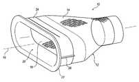
- FIG. 1is a perspective view of a braided shield according to an embodiment
- FIG. 2is a perspective view of a housing having an outer layer and an inner layer integrally formed with the outer layer;
- FIG. 3is a cross-sectional side view of the braided shield of FIG. 1 according to an embodiment
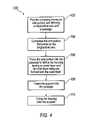
- FIG. 4is a flow chart of a method of forming the braided shield according to an embodiment.
- a braided shieldincludes a housing having a dual-layer configuration.
- the housingis formed from a plurality of wires braided together and has an outer layer integrally formed with an inner layer to establish the dual-layer configuration.
- a supportis at least partially disposed in the housing, and the inner layer is disposed between the support and the outer layer.
- the inner layer and outer layerreduce the amount of electromagnetic radiation that leaks into or out of the housing by reducing the number of holes in the housing.
- Forming the braided shieldincludes providing the housing, which defines a longitudinal axis and a passage extending along the longitudinal axis.
- the housinghas an end portion, and the end portion is compressed transverse to the longitudinal axis. The end portion is then forced into the passage.
- the braided shieldhelps prevent the plurality of wires from unraveling and reduces corrosion between the housing and the support. Accordingly, the braided shield provided herein reduces or eliminates the number of holes in the shield to reduce or eliminate electromagnetic radiation from entering or exiting a cable while providing a strong and consistent crimp with the support.
- a cablemay be useful in any industry or application, including, but not limited to, an electric vehicle's propulsion system wiring to prevent from a radio or other electronic sources.
- FIG. 1is a perspective view of an exemplary embodiment of the braided shield 10 that includes a housing 12 with a dual-layer configuration.
- the housing 12has an outer layer 14 and an inner layer 16 integrally formed to establish the dual-layer configuration.
- the outer layer 14 and the inner layer 16need not be integrally formed. Instead, the inner layer 16 may be a separate piece that is inserted into the outer layer 14 .
- the housing 12including the outer layer 14 and the inner layer 16 , may be formed from a plurality of wires braided together to block interference from electromagnetic radiation while remaining flexible.
- the housing 12may be formed from any type of wire known, including, but not limited to, copper or copper coated with tin. As shown in FIG. 1 , the housing 12 has a generally cylindrical shape, although it is to be appreciated that the housing 12 may be formed to any shape. Indeed, a portion of the housing 12 may have one shape and another portion of the housing 12 may have another shape. For instance, a portion of the housing 12 may have a generally cylindrical shape, while another portion of the housing 12 may have a generally elliptical shape. In either embodiment, the housing 12 defines a longitudinal axis 18 extending along a length of the housing 12 . The housing 12 further defines a passage 20 through the length of the housing 12 along the longitudinal axis 18 .
- a support 22is at least partially disposed in the passage 20 of the housing 12 .
- the support 22has a relatively rigid structure for generally retaining the shape of the housing 12 when assembled.
- the support 22may be formed from any known material.
- the support 22may be formed from steel or aluminum.
- the support 22may be coated with a metal such as tin. It is to be appreciated that the support 22 may be formed from or coated with other materials known in the art.
- a crimp band 24is disposed on the outer layer 14 for securing the support 22 to the housing 12 .
- the crimp band 24may be formed from any material known in the art.
- the crimp band 24may be formed from steel and plated with tin.
- the crimp band 24includes at least one crimp end 26 that may be compressed, effectively shortening the circumference of the crimp band 24 . When the crimp end 26 is compressed, the crimp band 24 holds the housing 12 and the support 22 together free from any nut and bolt as shown in the drawings.
- FIG. 2is a perspective view of an exemplary embodiment of the housing 12 .
- the inner layer 16is integrally formed with the outer layer 14 . Since the inner layer 16 is integrally formed with the outer layer 14 , the inner layer 16 is also formed from the plurality of wires braided together.
- FIG. 3is a cross-sectional side view of an exemplary embodiment of the braided shield 10 .
- the inner layer 16is folded into the outer layer 14 to establish the dual-layered configuration.
- the outer layer 14has an exposed surface 28 and an internal surface 30 .
- the support 22is disposed in the passage 20 spaced from the internal surface 30 of the outer layer 14 .
- the inner layer 16is disposed at least partially between the outer layer 14 and the support 22 .
- the inner layer 16has an exposed surface 32 and an internal surface 34 . At least a portion of the internal surface 34 of the inner layer 16 is disposed on at least a portion of the internal surface 30 of the outer layer 14 .
- the internal surface 30 of the outer layer 14is the same as the internal surface 34 of the inner layer 16 .
- the support 22is disposed on the exposed surface 32 of the inner layer 16 .
- the inner layer 16defines at least a portion of the passage 20 , and the support 22 is disposed on the internal surface 34 of the inner layer 16 inside the passage 20 .
- the support 22may further include a lip 36 integrally formed with and extending from the support 22 transverse to the longitudinal axis 18 .
- the lip 36limits movement of the support 22 along the longitudinal axis 18 .
- the lip 36may also align the crimp band 24 with the end of the housing 12 .
- FIG. 4is a flowchart of an exemplary embodiment of a method 100 of forming the braided shield 10 .
- the method 100includes a step 102 of providing the housing 12 having an end portion and defining the longitudinal axis 18 and the passage 20 extending along the longitudinal axis 18 .
- Providing the housing 12may include braiding a plurality of wires to form the housing 12 and/or designating a portion of the housing 12 as the end portion.
- the method 100also includes a step 104 of compressing the end portion transverse to the longitudinal axis 18 .
- the method 100includes a step 106 of forcing the end portion into the passage 20 to define the housing 12 having an outer layer 14 and an inner layer 16 integrally formed with the outer layer 14 .
- the step 106 of forcing the end portion into the housing 12may include compressing the housing 12 along the longitudinal axis 18 , expanding the outer layer 14 , and/or folding the inner layer 16 into the passage 20 .
- the method 100may include a step 108 of inserting the support 22 into the passage 20 .
- the method 100may include a step 110 of crimping the housing 12 onto the support 22 .
- Crimping the housing 12may include clamping the crimp band 24 onto the housing 12 .
Landscapes
- Engineering & Computer Science (AREA)
- Microelectronics & Electronic Packaging (AREA)
- Shielding Devices Or Components To Electric Or Magnetic Fields (AREA)
Abstract
Description
Claims (8)
Priority Applications (2)
| Application Number | Priority Date | Filing Date | Title |
|---|---|---|---|
| US11/986,324US7674972B2 (en) | 2007-11-21 | 2007-11-21 | Fold-in braided shield |
| EP08169071AEP2063697A1 (en) | 2007-11-21 | 2008-11-13 | Fold-in braided shield |
Applications Claiming Priority (1)
| Application Number | Priority Date | Filing Date | Title |
|---|---|---|---|
| US11/986,324US7674972B2 (en) | 2007-11-21 | 2007-11-21 | Fold-in braided shield |
Publications (2)
| Publication Number | Publication Date |
|---|---|
| US20090126987A1 US20090126987A1 (en) | 2009-05-21 |
| US7674972B2true US7674972B2 (en) | 2010-03-09 |
Family
ID=40473479
Family Applications (1)
| Application Number | Title | Priority Date | Filing Date |
|---|---|---|---|
| US11/986,324ActiveUS7674972B2 (en) | 2007-11-21 | 2007-11-21 | Fold-in braided shield |
Country Status (2)
| Country | Link |
|---|---|
| US (1) | US7674972B2 (en) |
| EP (1) | EP2063697A1 (en) |
Cited By (13)
| Publication number | Priority date | Publication date | Assignee | Title |
|---|---|---|---|---|
| US20120035697A1 (en)* | 2009-04-30 | 2012-02-09 | Stone Richard T | Shielded implantable medical lead with guarded termination |
| US8535085B1 (en)* | 2012-04-12 | 2013-09-17 | Event Horizon, L.L.C. | Electrical connector backshell adaptor assembly |
| US20140238735A1 (en)* | 2011-11-25 | 2014-08-28 | Yazaki Corporation | Shielding construction and wiring harness |
| US20140370753A1 (en)* | 2011-04-14 | 2014-12-18 | Yazaki Corporation | Shielded connector |
| US9259572B2 (en) | 2007-04-25 | 2016-02-16 | Medtronic, Inc. | Lead or lead extension having a conductive body and conductive body contact |
| US20160056550A1 (en)* | 2013-05-31 | 2016-02-25 | Kostal Kontact Systeme GmbH | Contact Element |
| US9302101B2 (en) | 2004-03-30 | 2016-04-05 | Medtronic, Inc. | MRI-safe implantable lead |
| US9463317B2 (en) | 2012-04-19 | 2016-10-11 | Medtronic, Inc. | Paired medical lead bodies with braided conductive shields having different physical parameter values |
| US9731119B2 (en) | 2008-03-12 | 2017-08-15 | Medtronic, Inc. | System and method for implantable medical device lead shielding |
| US9993638B2 (en) | 2013-12-14 | 2018-06-12 | Medtronic, Inc. | Devices, systems and methods to reduce coupling of a shield and a conductor within an implantable medical lead |
| US10155111B2 (en) | 2014-07-24 | 2018-12-18 | Medtronic, Inc. | Methods of shielding implantable medical leads and implantable medical lead extensions |
| US10279171B2 (en) | 2014-07-23 | 2019-05-07 | Medtronic, Inc. | Methods of shielding implantable medical leads and implantable medical lead extensions |
| US10398893B2 (en) | 2007-02-14 | 2019-09-03 | Medtronic, Inc. | Discontinuous conductive filler polymer-matrix composites for electromagnetic shielding |
Families Citing this family (3)
| Publication number | Priority date | Publication date | Assignee | Title |
|---|---|---|---|---|
| JP6169371B2 (en)* | 2013-02-28 | 2017-07-26 | 矢崎総業株式会社 | Shield member and manufacturing method thereof |
| JP6080703B2 (en)* | 2013-06-18 | 2017-02-15 | 矢崎総業株式会社 | Shield unit |
| JP6182424B2 (en)* | 2013-10-25 | 2017-08-16 | 矢崎総業株式会社 | Shield unit and manufacturing method thereof |
Citations (16)
| Publication number | Priority date | Publication date | Assignee | Title |
|---|---|---|---|---|
| US3648224A (en) | 1970-03-04 | 1972-03-07 | Molex Products Co | Shielded cable connector |
| US4497533A (en) | 1982-06-21 | 1985-02-05 | Chomerics, Inc. | Shielded cable system and method |
| US5028742A (en) | 1990-03-20 | 1991-07-02 | Minnesota Mining And Manufacturing Company | Cable shield connector |
| US5267878A (en) | 1990-03-05 | 1993-12-07 | Yazaki Corporation | Electrical connector for shielding cable |
| US5329064A (en) | 1992-10-02 | 1994-07-12 | Belden Wire & Cable Company | Superior shield cable |
| US5496968A (en) | 1993-04-30 | 1996-03-05 | Yazaki Corporation | Shielded cable connecting terminal |
| US5709450A (en)* | 1995-12-27 | 1998-01-20 | General Motors Corporation | High intensity discharge automotive lamp socket |
| US6048227A (en) | 1997-06-19 | 2000-04-11 | Itt Manufacturing Enterprises, Inc. | Connector backshell |
| US6107572A (en) | 1994-07-29 | 2000-08-22 | Sumitomo Wiring Systems, Ltd. | Terminal-processed structure of shielded cable and terminal-processing method of the same |
| US20020134565A1 (en) | 2001-03-26 | 2002-09-26 | Yazaki Corporation | Electromagnetic shielding structure |
| US20030092321A1 (en) | 2001-11-10 | 2003-05-15 | Nexans | Arrangement for attaching a plug-in connector to a shielded electric line |
| US6648690B2 (en) | 2001-01-17 | 2003-11-18 | Yazaki Corporation | Terminal end structure for shielded wire |
| US20030221850A1 (en) | 2002-03-08 | 2003-12-04 | Autonetworks Technologies, Ltd. | Shielded wire |
| US20050266729A1 (en) | 2004-05-26 | 2005-12-01 | Yazaki Corporation | Shielded-conductor cable fixing construction |
| US7228625B1 (en) | 2006-07-12 | 2007-06-12 | Yazaki North America, Inc. | Method for attaching an electrical cable to a connector shield |
| US20080254665A1 (en) | 2007-04-10 | 2008-10-16 | Deutsch Engineered Connecting Devices, Inc. | Modular interconnect system and apparatus |
Family Cites Families (4)
| Publication number | Priority date | Publication date | Assignee | Title |
|---|---|---|---|---|
| DE3242073A1 (en)* | 1982-11-13 | 1984-05-17 | kabelmetal electro GmbH, 3000 Hannover | Bushing for an electrical lead |
| US6087584A (en)* | 1998-06-30 | 2000-07-11 | Lucent Technologies Inc. | Tubular cable grounding mechanism |
| JP2002231394A (en)* | 2001-01-30 | 2002-08-16 | Auto Network Gijutsu Kenkyusho:Kk | Shield connector and manufacturing method thereof |
| NL1026698C2 (en)* | 2004-07-21 | 2006-01-30 | Framatome Connectors Int | Cable connector assembly with recoverable end of the shielding cover. |
- 2007
- 2007-11-21USUS11/986,324patent/US7674972B2/enactiveActive
- 2008
- 2008-11-13EPEP08169071Apatent/EP2063697A1/ennot_activeWithdrawn
Patent Citations (17)
| Publication number | Priority date | Publication date | Assignee | Title |
|---|---|---|---|---|
| US3648224A (en) | 1970-03-04 | 1972-03-07 | Molex Products Co | Shielded cable connector |
| US4497533A (en) | 1982-06-21 | 1985-02-05 | Chomerics, Inc. | Shielded cable system and method |
| US5267878A (en) | 1990-03-05 | 1993-12-07 | Yazaki Corporation | Electrical connector for shielding cable |
| US5028742A (en) | 1990-03-20 | 1991-07-02 | Minnesota Mining And Manufacturing Company | Cable shield connector |
| US5329064A (en) | 1992-10-02 | 1994-07-12 | Belden Wire & Cable Company | Superior shield cable |
| US5496968A (en) | 1993-04-30 | 1996-03-05 | Yazaki Corporation | Shielded cable connecting terminal |
| US6107572A (en) | 1994-07-29 | 2000-08-22 | Sumitomo Wiring Systems, Ltd. | Terminal-processed structure of shielded cable and terminal-processing method of the same |
| US5709450A (en)* | 1995-12-27 | 1998-01-20 | General Motors Corporation | High intensity discharge automotive lamp socket |
| US6048227A (en) | 1997-06-19 | 2000-04-11 | Itt Manufacturing Enterprises, Inc. | Connector backshell |
| US6648690B2 (en) | 2001-01-17 | 2003-11-18 | Yazaki Corporation | Terminal end structure for shielded wire |
| US20020134565A1 (en) | 2001-03-26 | 2002-09-26 | Yazaki Corporation | Electromagnetic shielding structure |
| US20030092321A1 (en) | 2001-11-10 | 2003-05-15 | Nexans | Arrangement for attaching a plug-in connector to a shielded electric line |
| US20030221850A1 (en) | 2002-03-08 | 2003-12-04 | Autonetworks Technologies, Ltd. | Shielded wire |
| US20050266729A1 (en) | 2004-05-26 | 2005-12-01 | Yazaki Corporation | Shielded-conductor cable fixing construction |
| US7228625B1 (en) | 2006-07-12 | 2007-06-12 | Yazaki North America, Inc. | Method for attaching an electrical cable to a connector shield |
| US20080254665A1 (en) | 2007-04-10 | 2008-10-16 | Deutsch Engineered Connecting Devices, Inc. | Modular interconnect system and apparatus |
| US7494384B2 (en)* | 2007-04-10 | 2009-02-24 | Deutsch Engineered Connecting Devices, Inc. | Modular interconnect system and apparatus |
Non-Patent Citations (1)
| Title |
|---|
| European Search Report dated Mar. 31, 2009. |
Cited By (28)
| Publication number | Priority date | Publication date | Assignee | Title |
|---|---|---|---|---|
| US9302101B2 (en) | 2004-03-30 | 2016-04-05 | Medtronic, Inc. | MRI-safe implantable lead |
| US10398893B2 (en) | 2007-02-14 | 2019-09-03 | Medtronic, Inc. | Discontinuous conductive filler polymer-matrix composites for electromagnetic shielding |
| US9259572B2 (en) | 2007-04-25 | 2016-02-16 | Medtronic, Inc. | Lead or lead extension having a conductive body and conductive body contact |
| US9731119B2 (en) | 2008-03-12 | 2017-08-15 | Medtronic, Inc. | System and method for implantable medical device lead shielding |
| US9452284B2 (en) | 2009-04-30 | 2016-09-27 | Medtronic, Inc. | Termination of a shield within an implantable medical lead |
| US11260222B2 (en) | 2009-04-30 | 2022-03-01 | Medtronic, Inc. | Radiopaque markers for implantable medical leads, devices, and systems |
| US9216286B2 (en)* | 2009-04-30 | 2015-12-22 | Medtronic, Inc. | Shielded implantable medical lead with guarded termination |
| US9220893B2 (en) | 2009-04-30 | 2015-12-29 | Medtronic, Inc. | Shielded implantable medical lead with reduced torsional stiffness |
| US9186499B2 (en) | 2009-04-30 | 2015-11-17 | Medtronic, Inc. | Grounding of a shield within an implantable medical lead |
| US12409320B2 (en) | 2009-04-30 | 2025-09-09 | Medtronic, Inc. | Termination of a shield within an implantable medical lead |
| US9272136B2 (en) | 2009-04-30 | 2016-03-01 | Medtronic, Inc. | Grounding of a shield within an implantable medical lead |
| US10035014B2 (en) | 2009-04-30 | 2018-07-31 | Medtronic, Inc. | Steering an implantable medical lead via a rotational coupling to a stylet |
| US9956402B2 (en) | 2009-04-30 | 2018-05-01 | Medtronic, Inc. | Radiopaque markers for implantable medical leads, devices, and systems |
| US10086194B2 (en) | 2009-04-30 | 2018-10-02 | Medtronic, Inc. | Termination of a shield within an implantable medical lead |
| US20120035697A1 (en)* | 2009-04-30 | 2012-02-09 | Stone Richard T | Shielded implantable medical lead with guarded termination |
| US9205253B2 (en) | 2009-04-30 | 2015-12-08 | Medtronic, Inc. | Shielding an implantable medical lead |
| US9629998B2 (en) | 2009-04-30 | 2017-04-25 | Medtronics, Inc. | Establishing continuity between a shield within an implantable medical lead and a shield within an implantable lead extension |
| US9318849B2 (en)* | 2011-04-14 | 2016-04-19 | Yazaki Corporation | Shielded connector |
| US20140370753A1 (en)* | 2011-04-14 | 2014-12-18 | Yazaki Corporation | Shielded connector |
| US9345180B2 (en)* | 2011-11-25 | 2016-05-17 | Yazaki Corporation | Shielding construction and wiring harness |
| US20140238735A1 (en)* | 2011-11-25 | 2014-08-28 | Yazaki Corporation | Shielding construction and wiring harness |
| US8535085B1 (en)* | 2012-04-12 | 2013-09-17 | Event Horizon, L.L.C. | Electrical connector backshell adaptor assembly |
| US9463317B2 (en) | 2012-04-19 | 2016-10-11 | Medtronic, Inc. | Paired medical lead bodies with braided conductive shields having different physical parameter values |
| US9692146B2 (en)* | 2013-05-31 | 2017-06-27 | Kostal Kontakt Systeme Gmbh | Contact element |
| US20160056550A1 (en)* | 2013-05-31 | 2016-02-25 | Kostal Kontact Systeme GmbH | Contact Element |
| US9993638B2 (en) | 2013-12-14 | 2018-06-12 | Medtronic, Inc. | Devices, systems and methods to reduce coupling of a shield and a conductor within an implantable medical lead |
| US10279171B2 (en) | 2014-07-23 | 2019-05-07 | Medtronic, Inc. | Methods of shielding implantable medical leads and implantable medical lead extensions |
| US10155111B2 (en) | 2014-07-24 | 2018-12-18 | Medtronic, Inc. | Methods of shielding implantable medical leads and implantable medical lead extensions |
Also Published As
| Publication number | Publication date |
|---|---|
| EP2063697A1 (en) | 2009-05-27 |
| US20090126987A1 (en) | 2009-05-21 |
Similar Documents
| Publication | Publication Date | Title |
|---|---|---|
| US7674972B2 (en) | Fold-in braided shield | |
| US7692096B2 (en) | Electromagnetically shielded cable | |
| US7491071B2 (en) | Shield end processing structure | |
| US9472931B2 (en) | Seal structure for wire harness | |
| US20090308632A1 (en) | Shielded conductor | |
| US9718365B2 (en) | Wiring member | |
| US6674005B2 (en) | Electromagnetic shielding structure for electric wire | |
| US10277017B2 (en) | Exterior member and wire harness | |
| US9966166B2 (en) | Shielded conduction path | |
| US20140179161A1 (en) | Wire harness and connection structure of shield shell and braided shield | |
| US10320165B2 (en) | Shielded conduction path | |
| US20170271047A1 (en) | Shielded conductor | |
| WO2014050754A1 (en) | Method for producing wire harness | |
| US12230932B2 (en) | Wire harness | |
| US20180083433A1 (en) | Terminal fitting fixing structure and wire harness | |
| US20170129423A1 (en) | Shielded conductive path | |
| US20160229359A1 (en) | Shielded pipe | |
| WO2017221675A1 (en) | Grommet and wire harness | |
| US9462730B2 (en) | Shield member and method for manufacturing the same | |
| US10189424B2 (en) | Structure for connecting electric wires and wire harness | |
| US9889805B2 (en) | Wire harness and wire harness manufacturing method | |
| CN112332174A (en) | Cable shielding layer grounding structure and method considering electromagnetic shielding and lightweight design | |
| US20240405536A1 (en) | Wire harness | |
| US10630003B2 (en) | Conductor connecting structure and wire harness | |
| US20200106248A1 (en) | Electromagnetic shield component, wire harness, and method for manufacturing electromagnetic shield component |
Legal Events
| Date | Code | Title | Description |
|---|---|---|---|
| AS | Assignment | Owner name:DELPHI TECHNOLOGIES, INC., MICHIGAN Free format text:ASSIGNMENT OF ASSIGNORS INTEREST;ASSIGNORS:GLADD, JOSEPH H.;KETTERER, WILLIAM C.;ESENWEIN, FREDERICK D.;REEL/FRAME:020193/0800 Effective date:20071115 Owner name:DELPHI TECHNOLOGIES, INC.,MICHIGAN Free format text:ASSIGNMENT OF ASSIGNORS INTEREST;ASSIGNORS:GLADD, JOSEPH H.;KETTERER, WILLIAM C.;ESENWEIN, FREDERICK D.;REEL/FRAME:020193/0800 Effective date:20071115 | |
| STCF | Information on status: patent grant | Free format text:PATENTED CASE | |
| FPAY | Fee payment | Year of fee payment:4 | |
| MAFP | Maintenance fee payment | Free format text:PAYMENT OF MAINTENANCE FEE, 8TH YEAR, LARGE ENTITY (ORIGINAL EVENT CODE: M1552) Year of fee payment:8 | |
| AS | Assignment | Owner name:APTIV TECHNOLOGIES LIMITED, BARBADOS Free format text:ASSIGNMENT OF ASSIGNORS INTEREST;ASSIGNOR:DELPHI TECHNOLOGIES INC.;REEL/FRAME:047143/0874 Effective date:20180101 | |
| MAFP | Maintenance fee payment | Free format text:PAYMENT OF MAINTENANCE FEE, 12TH YEAR, LARGE ENTITY (ORIGINAL EVENT CODE: M1553); ENTITY STATUS OF PATENT OWNER: LARGE ENTITY Year of fee payment:12 | |
| AS | Assignment | Owner name:APTIV TECHNOLOGIES (2) S.A R.L., LUXEMBOURG Free format text:ENTITY CONVERSION;ASSIGNOR:APTIV TECHNOLOGIES LIMITED;REEL/FRAME:066746/0001 Effective date:20230818 Owner name:APTIV MANUFACTURING MANAGEMENT SERVICES S.A R.L., LUXEMBOURG Free format text:MERGER;ASSIGNOR:APTIV TECHNOLOGIES (2) S.A R.L.;REEL/FRAME:066566/0173 Effective date:20231005 Owner name:APTIV TECHNOLOGIES AG, SWITZERLAND Free format text:ASSIGNMENT OF ASSIGNORS INTEREST;ASSIGNOR:APTIV MANUFACTURING MANAGEMENT SERVICES S.A R.L.;REEL/FRAME:066551/0219 Effective date:20231006 |