US7674691B2 - Method of manufacturing an electrical antifuse - Google Patents
Method of manufacturing an electrical antifuseDownload PDFInfo
- Publication number
- US7674691B2 US7674691B2US11/683,068US68306807AUS7674691B2US 7674691 B2US7674691 B2US 7674691B2US 68306807 AUS68306807 AUS 68306807AUS 7674691 B2US7674691 B2US 7674691B2
- Authority
- US
- United States
- Prior art keywords
- link
- silicide
- antifuse
- cathode
- anode
- Prior art date
- Legal status (The legal status is an assumption and is not a legal conclusion. Google has not performed a legal analysis and makes no representation as to the accuracy of the status listed.)
- Active, expires
Links
- 238000004519manufacturing processMethods0.000titleclaimsabstractdescription16
- FVBUAEGBCNSCDD-UHFFFAOYSA-Nsilicide(4-)Chemical compound[Si-4]FVBUAEGBCNSCDD-UHFFFAOYSA-N0.000claimsabstractdescription124
- 229910021332silicideInorganic materials0.000claimsabstractdescription110
- 239000000463materialSubstances0.000claimsabstractdescription63
- 238000000034methodMethods0.000claimsabstractdescription28
- 238000002955isolationMethods0.000claimsabstractdescription15
- 229910021420polycrystalline siliconInorganic materials0.000claimsdescription26
- 239000003989dielectric materialSubstances0.000claimsdescription18
- 239000002019doping agentSubstances0.000claimsdescription9
- 238000000059patterningMethods0.000claimsdescription7
- 125000006850spacer groupChemical group0.000claimsdescription7
- 230000000873masking effectEffects0.000claimsdescription3
- 239000004065semiconductorSubstances0.000abstractdescription82
- 239000002184metalSubstances0.000abstractdescription37
- 229910052751metalInorganic materials0.000abstractdescription37
- 239000000956alloySubstances0.000abstractdescription24
- 229910045601alloyInorganic materials0.000abstractdescription23
- 230000008569processEffects0.000abstractdescription11
- 230000005669field effectEffects0.000abstract1
- 239000010410layerSubstances0.000description58
- 238000005516engineering processMethods0.000description9
- 230000035945sensitivityEffects0.000description9
- 230000015572biosynthetic processEffects0.000description8
- 238000013461designMethods0.000description8
- 238000012545processingMethods0.000description7
- 239000000758substrateSubstances0.000description7
- SCCCLDWUZODEKG-UHFFFAOYSA-NgermanideChemical compound[GeH3-]SCCCLDWUZODEKG-UHFFFAOYSA-N0.000description6
- 238000000151depositionMethods0.000description5
- 238000010586diagramMethods0.000description4
- 238000009826distributionMethods0.000description4
- 229920005591polysiliconPolymers0.000description4
- 229910000577Silicon-germaniumInorganic materials0.000description3
- AXQKVSDUCKWEKE-UHFFFAOYSA-N[C].[Ge].[Si]Chemical compound[C].[Ge].[Si]AXQKVSDUCKWEKE-UHFFFAOYSA-N0.000description3
- LEVVHYCKPQWKOP-UHFFFAOYSA-N[Si].[Ge]Chemical compound[Si].[Ge]LEVVHYCKPQWKOP-UHFFFAOYSA-N0.000description3
- 238000005468ion implantationMethods0.000description3
- 150000004767nitridesChemical class0.000description3
- 229910021483silicon-carbon alloyInorganic materials0.000description3
- 229910001339C alloyInorganic materials0.000description2
- XUIMIQQOPSSXEZ-UHFFFAOYSA-NSiliconChemical compound[Si]XUIMIQQOPSSXEZ-UHFFFAOYSA-N0.000description2
- 238000003491arrayMethods0.000description2
- 230000008901benefitEffects0.000description2
- 230000000903blocking effectEffects0.000description2
- 230000015556catabolic processEffects0.000description2
- 230000008021depositionEffects0.000description2
- 238000001514detection methodMethods0.000description2
- 230000006870functionEffects0.000description2
- 238000011065in-situ storageMethods0.000description2
- 239000012212insulatorSubstances0.000description2
- 238000001459lithographyMethods0.000description2
- 238000005259measurementMethods0.000description2
- 229910052710siliconInorganic materials0.000description2
- 239000010703siliconSubstances0.000description2
- 229910000927Ge alloyInorganic materials0.000description1
- 229910021417amorphous siliconInorganic materials0.000description1
- 229910052787antimonyInorganic materials0.000description1
- 229910052785arsenicInorganic materials0.000description1
- 229910052796boronInorganic materials0.000description1
- 230000008859changeEffects0.000description1
- 230000001010compromised effectEffects0.000description1
- 239000004020conductorSubstances0.000description1
- 230000007423decreaseEffects0.000description1
- 230000003247decreasing effectEffects0.000description1
- 230000002950deficientEffects0.000description1
- 238000006731degradation reactionMethods0.000description1
- 230000001419dependent effectEffects0.000description1
- 230000009977dual effectEffects0.000description1
- 230000000694effectsEffects0.000description1
- 230000005684electric fieldEffects0.000description1
- 239000012777electrically insulating materialSubstances0.000description1
- 238000005530etchingMethods0.000description1
- 230000020169heat generationEffects0.000description1
- 238000002513implantationMethods0.000description1
- 239000012535impuritySubstances0.000description1
- 239000011810insulating materialSubstances0.000description1
- 239000011229interlayerSubstances0.000description1
- 150000002500ionsChemical class0.000description1
- 238000004518low pressure chemical vapour depositionMethods0.000description1
- 230000007246mechanismEffects0.000description1
- 238000001465metallisationMethods0.000description1
- 230000005012migrationEffects0.000description1
- 238000013508migrationMethods0.000description1
- 239000000203mixtureSubstances0.000description1
- 230000004048modificationEffects0.000description1
- 238000012986modificationMethods0.000description1
- 229910021421monocrystalline siliconInorganic materials0.000description1
- 229910052759nickelInorganic materials0.000description1
- 229920002120photoresistant polymerPolymers0.000description1
- 229910052697platinumInorganic materials0.000description1
- 230000009467reductionEffects0.000description1
- 239000003870refractory metalSubstances0.000description1
- 238000003860storageMethods0.000description1
- 229910052715tantalumInorganic materials0.000description1
- 229910052719titaniumInorganic materials0.000description1
- 238000012546transferMethods0.000description1
- 229910052721tungstenInorganic materials0.000description1
- 238000001039wet etchingMethods0.000description1
Images


Classifications
- H—ELECTRICITY
- H01—ELECTRIC ELEMENTS
- H01L—SEMICONDUCTOR DEVICES NOT COVERED BY CLASS H10
- H01L23/00—Details of semiconductor or other solid state devices
- H01L23/52—Arrangements for conducting electric current within the device in operation from one component to another, i.e. interconnections, e.g. wires, lead frames
- H01L23/522—Arrangements for conducting electric current within the device in operation from one component to another, i.e. interconnections, e.g. wires, lead frames including external interconnections consisting of a multilayer structure of conductive and insulating layers inseparably formed on the semiconductor body
- H01L23/525—Arrangements for conducting electric current within the device in operation from one component to another, i.e. interconnections, e.g. wires, lead frames including external interconnections consisting of a multilayer structure of conductive and insulating layers inseparably formed on the semiconductor body with adaptable interconnections
- H01L23/5252—Arrangements for conducting electric current within the device in operation from one component to another, i.e. interconnections, e.g. wires, lead frames including external interconnections consisting of a multilayer structure of conductive and insulating layers inseparably formed on the semiconductor body with adaptable interconnections comprising anti-fuses, i.e. connections having their state changed from non-conductive to conductive
- H—ELECTRICITY
- H10—SEMICONDUCTOR DEVICES; ELECTRIC SOLID-STATE DEVICES NOT OTHERWISE PROVIDED FOR
- H10D—INORGANIC ELECTRIC SEMICONDUCTOR DEVICES
- H10D84/00—Integrated devices formed in or on semiconductor substrates that comprise only semiconducting layers, e.g. on Si wafers or on GaAs-on-Si wafers
- H10D84/01—Manufacture or treatment
- H—ELECTRICITY
- H01—ELECTRIC ELEMENTS
- H01L—SEMICONDUCTOR DEVICES NOT COVERED BY CLASS H10
- H01L21/00—Processes or apparatus adapted for the manufacture or treatment of semiconductor or solid state devices or of parts thereof
- H01L21/02—Manufacture or treatment of semiconductor devices or of parts thereof
- H01L21/04—Manufacture or treatment of semiconductor devices or of parts thereof the devices having potential barriers, e.g. a PN junction, depletion layer or carrier concentration layer
- H01L21/34—Manufacture or treatment of semiconductor devices or of parts thereof the devices having potential barriers, e.g. a PN junction, depletion layer or carrier concentration layer the devices having semiconductor bodies not provided for in groups H01L21/18, H10D48/04 and H10D48/07, with or without impurities, e.g. doping materials
- H01L21/44—Manufacture of electrodes on semiconductor bodies using processes or apparatus not provided for in groups H01L21/38 - H01L21/428
- H—ELECTRICITY
- H01—ELECTRIC ELEMENTS
- H01L—SEMICONDUCTOR DEVICES NOT COVERED BY CLASS H10
- H01L23/00—Details of semiconductor or other solid state devices
- H01L23/58—Structural electrical arrangements for semiconductor devices not otherwise provided for, e.g. in combination with batteries
- H01L23/62—Protection against overvoltage, e.g. fuses, shunts
- H—ELECTRICITY
- H01—ELECTRIC ELEMENTS
- H01L—SEMICONDUCTOR DEVICES NOT COVERED BY CLASS H10
- H01L2924/00—Indexing scheme for arrangements or methods for connecting or disconnecting semiconductor or solid-state bodies as covered by H01L24/00
- H01L2924/0001—Technical content checked by a classifier
- H01L2924/0002—Not covered by any one of groups H01L24/00, H01L24/00 and H01L2224/00
Definitions
- the present inventiongenerally relates to electrical antifuses and, more particularly, to antifuses which are compatible with current CMOS manufacturing processes and which can be programmed easily, rapidly and with high reliability to alter electrical characteristics thereof by a readily detectable margin.
- fuses and antifuseshave become widespread in recent years, particularly for substituting spare circuits or circuit elements for defective circuits and circuit elements in order to increase manufacturing yield and avoid economic losses due to costs incurred in fabricating an integrated circuit which may not meet required specifications. Further, fuses and antifuses have been used to tailor circuit parameters for optimal performance and to electronically identify chips such as radio frequency (RF) chip identification. In recent years, fuses, in which resistance is increased during programming, and antifuses, in which resistance is decreased during programming, have also found applications in structures of choice for so-called “write once read many (WORM)” non-volatile memory cells.
- WORMwrite once read many
- antifuseshave numerous serious drawbacks.
- antifuseshave been fabricated as a sandwich of two regions of conductive material separated by an insulating layer which can be broken down by a current developed by a suitably high programming voltage (e.g. typically above 6 volts).
- a suitably high programming voltagee.g. typically above 6 volts.
- a severe trade-offexists between the level of the required high programming voltage and the potential for damage to other circuits on the chip and reliable operation of the programmed antifuse at lower voltages (e.g. about 5 volts or less). Good reproducibility of programming results is also difficult to achieve.
- the dielectric layerpresents substantial capacitance which slows circuit operation, particularly where numerous, unprogrammed antifuses exist on a single word or bit line.
- a low pressure chemical vapor deposition processwhich is required to deposit the dielectric with high uniformity in the film composition and thickness, may induce the formation of so-called hillocks in the first metallic layer.
- Another antifuse structurecomprises an interlayer of amorphous silicon (having a thickness about twenty times greater or more than the dielectric sandwich described above for comparable programming voltages) sandwiched between first and second layers of metal.
- amorphous siliconhaving a thickness about twenty times greater or more than the dielectric sandwich described above for comparable programming voltages
- Such structureshave extremely high leakage currents which can cause serious problems of controllability of programming and, in turn, severe storage time degradation problems. Additionally, such structures may be prone to crack propagation and continuity failure over long periods of use.
- an antifusewhich comprises an anode having an anode semiconductor and an anode silicide, a cathode having a cathode semiconductor and a cathode silicide, a link having a first silicided portion adjoining the anode and containing a first link semiconductor and a first link silicide, a second silicided portion adjoining the cathode and containing a second link semiconductor and a second silicide, and an unsilicided portion containing a third link semiconductor adjoining the first link semiconductor and the second link semiconductor.
- Each of the anode semiconductor, the cathode semiconductor, the first link semiconductor, the second semiconductor, and the third semiconductorpreferably comprises a material selected from the group consisting of polysilicon, polycrystalline silicon-germanium alloy, polycrystalline silicon-carbon alloy, polycrystalline silicon-germanium-carbon alloy.
- each of the anode silicide, the cathode silicide, the first silicide, and the second silicidecomprises a material selected from the group consisting of a metal silicide, a metal silicide-metal germanide alloy, a metal silicide-metal carbide alloy, or a metal silicide-metal carbide-metal germanide alloy.
- the antifusefurther comprises shallow trench isolation, wherein the shallow trench isolation is located directly beneath the cathode, the anode, and the link.
- the antifusecomprises a dielectric material mask located directly on the third link semiconductor and not directly on the first link semiconductor or the second link semiconductor.
- the unsilicided portionhas a length to width ratio in the range from about 1.5:1 to 12:1, and preferably in the range from about 3:1 to 8:1.
- the antifusemay further comprise a sidewall spacer at a periphery of the anode, the link and the cathode.
- at least the cathode semiconductoris doped with dopants.
- the anode semiconductor, the first link semiconductor, the second link semiconductor, and the third link semiconductormay or may not be doped.
- a method of programming an antifuse having an anode, a cathode, and a link containing an unsilicided portioncomprises the steps of electromigrating a silicide containing material into the unsilicided portion of the link; and reducing the resistance of the antifuse.
- a weakly depleted silicide regionis formed in the cathode during the electromigrating, wherein the weakly depleted silicide region adjoins the link and is devoid of the silicide containing material.
- the electromigrationis preferably performed through a voltage pulse across the anode and the cathode.
- the methodmay include a further step of electromigrating material from the link toward the anode to form an electromigrated semiconductor portion in the link which does not contain a significant concentration of silicide or a silicide alloy but substantially contains only a semiconductor material.
- the materialmay be electromigrated from the link toward the cathode to form an electromigrated semiconductor portion in the link.
- the resistance of the antifuseincreases during such electromigrating of material from the link toward the anode.
- a strongly silicide depleted regionis formed from the weakly silicide depleted region, wherein the strongly silicide depleted region has a larger area than the weakly silicide depleted region.
- a method of manufacturing an antifusecomprises the steps of patterning a polycrystalline silicon containing material layer to form a shape containing an anode, a cathode, and a link, wherein the link connects the anode and the cathode, masking a portion of the link with a dielectric material mask and forming a silicide containing material directly on portions of the shape exposed by the mask.
- the methodfurther comprises the step of forming contacts on the anode and the cathode capable of carrying a sufficient current to cause electromigration of material within the link.
- dopantsare introduced into at least the polycrystalline silicon containing material layer within the cathode by in-situ doping or by ion implantation.
- the methodfurther comprises the steps of forming a dielectric material layer on the shape; and lithographically patterning the dielectric material layer to form the dielectric material layer.
- the portion of the linkhas a length and a width, wherein the ratio of the length to width is in the range from about 1.5:1 to about 12:1, and more preferably in the range from about 3:1 to 8:1.
- the methodpreferably further comprises forming shallow trench isolation prior to the patterning of the polycrystalline silicon containing material layer, forming a sidewall spacer at a periphery of the anode, the link and the cathode; and forming a middle-of-line dielectric over the anode, the link and the cathode.
- FIG. 1is a schematic plan view of an antifuse in accordance with the present invention, as fabricated, that is, as unprogrammed,
- FIG. 2is a schematic plan view of an antifuse in accordance with the present invention, as programmed,
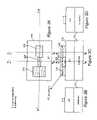
- FIGS. 3A , 3 B, 3 C and 3 Dillustrate plan and vertical sectional views of the antifuse in accordance with the invention during an initial stage of fabrication
- FIGS. 4A , 4 B, 4 C, 4 D, 5 A, 5 B, 5 C, 5 D, 6 A, 6 B, 6 C and 6 Dare plan and sectional views showing intermediate stages of fabrication
- FIGS. 7A , 7 B, 7 C and 7 Dillustrate plan and sectional views of the completed antifuse of FIG. 1 , (wherein, in FIGS. 3A-7D , in vertical sectional views, structure behind the plane of the respective sections is omitted for clarity),
- FIGS. 8A , 8 B, 8 C and 8 Dshow plan and vertical cross-sectional views similar to those of FIGS. 3-7 for a programmed antifuse in accordance with the present invention
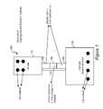
- FIG. 9is a schematic diagram of a suitable circuit for programming the antifuse in accordance with the present invention.
- FIG. 10shows plan and vertical cross-sectional views, similar to those of FIGS. 3-7 , for a twice programmed antifuse in accordance with the present invention
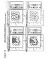
- FIGS. 11 and 12are histograms of resistance distribution before and after programming a first exemplary antifuse structure in accordance with the present invention under two different exemplary sets of programming parameters and different exemplary programming transistor structures, and
- FIG. 13provides contour diagrams for the negative logarithm of sense fail probability for sense amplifiers of differing sensitivity to determine the state of a programmed antifuse in accordance with the present invention (e.g. a programming window).
- the antifuse 100 in accordance with the present inventionincludes two enlarged rectangular terminal portions designated as an anode 110 and a cathode 120 , each of which preferably comprises a stack of a polycrystalline silicon containing material layer and a silicide containing layer.
- the present inventioncan also be implemented in other technologies such as in a monocrystalline layer over a buried oxide (BOX) layer in semiconductor-on-insulator technology or other embodiments which will be apparent to those skilled in the art in view of the following discussion which, for clarity, will be provided in connection with the preferred polysilicon structure but which should be understood as inclusive of and comprehending other technologies and materials.
- BOXburied oxide
- the preferred polycrystalline silicon containing material layeris located at the bottom, typically and preferably on top of shallow trench isolation, and the silicide containing layer is located directly on the polycrystalline silicon containing material layer.
- the polycrystalline silicon containing material layermay comprise polysilicon, polycrystalline silicon-germanium alloy, polycrystalline silicon-carbon alloy, polycrystalline silicon-germanium-carbon alloy, or other silicon containing alloy material that is polycrystalline in structure.
- the silicide containing layercomprises a silicide containing material, which may be a metal silicide, a metal silicide-metal germanide alloy, a metal silicide-metal carbide alloy, or a metal silicide-metal carbide-metal germanide alloy.
- the metal from which the silicide containing layer derivesmay be Ta, Ti, W, Co, Ni, Pt, other refractory metal, or an alloy thereof.
- Each portion of the polycrystalline silicon containing material layer and the silicide containing layermay be doped with dopants such as B, Ga, P, As, and Sb or alternatively undoped. Therefore, the anode 110 and the cathode 120 may or may not have the same doping in the polycrystalline silicon containing material layer or in the silicide containing layer.
- the polycrystalline silicon containing material layerhas a thickness from about 60 nm to about 150 nm, and preferably from about 80 nm to about 120 nm.
- the corresponding sheet resistance, or the resistance of a structure with a square geometryis about 600 Ohms per square.
- the silicon containing layertypically has a thickness from about 10 nm to about 40 nm, and preferably from about 15 nm to about 25 nm.
- the corresponding sheet resistanceis about 10 Ohms per square.
- the anode and cathodeare so denominated based on the intended direction of current flow during programming as well as in service, even though no diode or other non-linear conduction characteristic is exhibited, as will be discussed in further detail below.
- shape and size of the anode and cathodeare not particularly critical to the successful practice of the invention, it is preferred that the anode be somewhat smaller than the cathode and have a high aspect ratio in the direction of the link while the cathode is somewhat larger and of a lower aspect ratio in the direction of the link than the anode.
- Each of the anode 110 and cathode 120is also provided with electrical contacts such as the metal filled via contacts (CA) illustrated, which are preferred, and which are capable of carrying a sufficient current to cause electromigration of material (e.g. metal or silicide) and alloy formation.
- CAmetal filled via contacts
- the anode 110 and the cathode 120are connected by a link 125 which is narrower than the anode 110 or cathode 120 .
- the link 125preferably comprises three sections: a first silicided portion 130 adjoining the anode, a second silicided portion 140 adjoining the cathode 120 , and an unsilicided portion 150 between the first silicided portion 130 and the second silicided portion 140 .
- dimensionsare not particularly critical to successful practice of the invention but a nominal width of the link 125 of about 63 nm or minimum resolvable (or design rule) lithographic feature size of the lithography tools, if less, is preferred for application of the inventive antifuse to integrated circuit designs.
- Each of the length of first and second silicided portions ( 130 , 140 )preferably exceeds the overlay error tolerance of the mask utilized to form a silicide blocking nitride layer 510 ( FIG. 5A-5D ) as will be described below such that the silicide blocking nitride layer 510 does not contact the anode 110 or cathode 120 due to mask misalignment within manufacturing specification (i.e., in-spec overlay errors).
- the unsilicided portion 150 between portions 130 and 140is preferably of the same width as the unsilicided portion 150 and of a length in the range from about 1.5 times the width of the unsilicided portion 150 to about 12 times the width of the unsilicided portion 150 , and preferably in the range from about 3 times the width of the unsilicided portion 150 to about 8 times the width of the unsilicided portion 150 .
- the unsilicided portion 150 of link 125is provided to establish a conduction path of relatively high resistance between the anode and cathode which will allow the antifuse in accordance with the present invention to be electrically programmed and reliably read.
- Contactsare formed on the anode 110 and the cathode 120 so that the contacts are capable of carrying a sufficient current to cause electromigration of material within the link 125 , and preferably, also from the cathode 120 to move a silicide containing material into the unsilicided portion 150 of the link 125 .
- FIG. 2the structure of a programmed antifuse is shown in plan view similar to that of FIG. 1 .
- unsilicided portion 150 of FIG. 1has been silicided by the programming process and essentially merged with regions 130 and 140 to form a silicide migrated link 125 ′ by migration of the silicide containing layer from the second silicided portion 140 and a region of weakly silicide depleted region 160 .
- the silicide migrated linkcomprises the same material as the silicide containing layer.
- metal silicidetypically has a conductivity about two orders of magnitude higher than the conductivity of a heavily doped semiconductor
- the resistance of the silicide migrated link 125 ′is lower than the resistance of an unprogrammed link 125 . Due to the increased conductivity in the silicide migrated link 125 ′ compared with the unprogrammed link 125 , a substantial increase in the current flow from anode 110 to cathode 120 results compared with the current through an unprogrammed link 125 under similar bias conditions.
- the weakly silicide depleted region 160is semicircular (or semi-elliptical) with less material of the silicide containing layer per unit area than the remaining area of the cathode 120 .
- the dimensions and semicircular shape of the weakly silicide depleted region 160are determined by the electromigration mechanism that depends on the temperature and electric field gradient, which are dependent upon the electrical bias, the amount of electrical current, and the geometry of the cathode 120 and the link 125 .
- the weakly depleted silicided region 160will thus increase slightly in resistance but should retain sufficient conductivity for the programmed antifuse structure to pass more current than an unprogrammed antifuse under the same bias voltage across the anode 110 and the cathode 120 .
- the doping of the cathode 120is therefore important in ensuring that sufficient conductivity of region 160 will be maintained even though silicide is weakly depleted therein.
- a conductive link of controllable and generally constant geometry as well as low bulk resistanceis achieved by electromigration. This contrasts with prior art methods of narrowing or eliminating the conduction path as is generally the case with electromigration fuses.
- the resistance of an unprogrammed antifusedepends largely on the number of squares (a dimensionless number that measures the effect of geometry on sheet resistance, which, for example, may be the ratio of the length to width of a rectangular portion of a film) in the unsilicided portion 150 of an unprogrammed link 125 .
- each square in the geometry of the unsilicided portion 150generates about 600 Ohms. If the unsilicided portion 150 has a length to width ratio of 1.5, the resistance of the unsilicided portion is about 900 Ohms. If the unsilicided portion 150 has a length to width ratio of 3, the resistance of the unsilicided portion is about 1,800 Ohms.
- the resistance of the unsilicided portion 150is about 4,800 Ohms. If the unsilicided portion 150 has a length to width ratio of 12, the resistance of the unsilicided portion is about 7,200 Ohms
- an unprogrammed resistance of about 3000-4000 ohms and a reduced programmed resistance of generally less than 1000 Ohmscan be achieved although programmed resistance is somewhat variable in accordance with programming parameters as will be discussed in detail below.
- Such a resistance differentialis well within the detection capabilities of known sense amplifier designs currently used although other designs may be more appropriate to antifuses.
- views 3 A- 7 Aare plan views while views 3 B- 7 B.
- views 3 C- 7 C and 3 D- 7 Dare vertical cross-sectional views along the section lines B-B, C-C and D-D, respectively, indicated by dashed lines.
- isolation structuressuch as shallow trench isolation structure 370 in a semiconductor substrate 10 . Doing so allows the antifuse to be formed in regions not otherwise usable for other electrical elements on the chip while the isolation structure provides electrical isolation for the fuse when in service and additional protection against breakdown during programming at a voltage higher than otherwise likely to be present on the chip. Moreover, since isolation structures are formed of electrically insulating materials which usually exhibit poor thermal conductivity and isolation structures generally are formed with a substantial thickness, good thermal isolation is also provided by the isolation structure.
- the fuse body, or the polycrystalline silicon containing material layer portion of the anode 110 , cathode 120 , and the link 125may be formed by any known method such as depositing a layer of polycrystalline silicon containing material, application and lithographic patterning of a photoresist, and the transfer of the pattern into the polycrystalline silicon containing material layer by etching.
- An anode semiconductor 310is formed in the anode portion of the antifuse structure.
- a cathode semiconductor 320is formed in the cathode portion of the antifuse structure.
- a link semiconductor 325is formed in the link portion of the antifuse structure.
- the anode semiconductor 310 , the cathode semiconductor 320 , and the link semiconductor 325are thus contained within and collectively form the shape of the fuse body 300 .
- the material for the exemplary polycrystalline silicon containing material layeris as discussed above. This and other process steps which will be described below can be performed separately or simultaneously with other semiconductor manufacturing processing steps required for formation of transistors or other devices in MOS or other technologies. For example, both the polycrystalline silicon containing layer of the inventive antifuse structure may be formed during the same processing steps as gate electrodes of standard metal-oxide-semiconductor (MOS) devices on the same semiconductor substrate 10 .
- MOSmetal-oxide-semiconductor
- spacers 410are preferably formed, for example, by a conformal deposition of an insulating material layer followed by an anisotropic etch, such as a reactive ion etch (RIE).
- RIEreactive ion etch
- the spacers 410are formed with the same material and during the same processing steps as gate spacers of standard metal-oxide-semiconductor (MOS) devices on the same semiconductor substrate 10 .
- the spacers 410provide lateral structural support to the fuse body 300 and, together with the shallow trench isolation 370 and a middle-of-line dielectric 700 (Refer to FIG. 7 ), defines the volume of the antifuse structure within which materials may electromigrate.
- impuritiesmay be differentially supplied to the cathode 120 ( 310 ) by ion implantation while masking the link 125 ( 325 ) and anode 110 ( 320 ) with a block mask 420 .
- dopantis desired in both the link 125 and anode 110 , a desired amount of dopants may be supplied into the fuse body 300 by in-situ doping.
- Either an n-type or p-type dopantmay be used since its function is merely to increase conductivity of the polycrystalline silicon containing material layer within the cathode 120 such that the resistance of a programmed antifuse will not unduly increase when a portion of the silicide containing layer is depleted from the weakly silicide depleted region 160 during programming.
- the ion implantationcan be performed, for example, during the same processing steps as the implantation for the formation of source and drain regions of standard metal-oxide-semiconductor (MOS) devices on the same semiconductor substrate 10
- MOSmetal-oxide-semiconductor
- a dielectric material mask 510is formed by depositing and patterning a dielectric material layer such as nitride which can be etched selectively to other exposed materials.
- the link semiconductor 325is further divided into three parts by the location of the dielectric material mask 510 .
- a first link semiconductor 330is the portion of the link semiconductor 325 located between the dielectric material mask 510 and the anode semiconductor 310 .
- a second link semiconductor 340is the portion of the link semiconductor 325 located between the dielectric material mask 510 and the cathode semiconductor 320 .
- a third link semiconductor 350is the portion of the link semiconductor 325 located directly beneath the dielectric material mask 510 between the first link semiconductor 330 and the second link semiconductor 340 .
- the link semiconductor 325thus comprises the first link semiconductor 330 , the second link semiconductor 340 , and the third link semiconductor 350 .
- the dielectric material mask 510is preferably in the form of a stripe which defines the third link semiconductor 350 to protect against silicidation during a silicidation process.
- the silicidation processis typically performed by blanket deposition of a metal layer on the top surface of the semiconductor structure, followed by a silicidation anneal during which exposed portions (e.g. exposed to the metal deposition) of semiconductor material reacts with the metal layer and forms a silicide. Multiple anneals with different processing temperatures and different processing times may be employed to optimize the silicide.
- Semiconductor material covered with the dielectric material mask 510such as the third link semiconductor 350 does not react with the metal layer during the silicidation process, and consequently, no silicide is formed under the dielectric material mask 510 . Unreacted metal layer is subsequently removed, for example, by wet etching.
- FIGS. 6A-6DThe resulting exemplary structure is shown in FIGS. 6A-6D .
- a silicide containing layeris formed on top of each of the anode 110 , cathode 120 , and the first silicided portion 130 and the second silicided portion 140 of the link 125 .
- an anode silicide 610is formed directly on the anode semiconductor 310
- a cathode silicide 620is formed directly on the cathode semiconductor 320
- a first silicide 630is formed directly on the first link semiconductor 330
- a second silicide 640is formed directly on the second link semiconductor 340 .
- each of the anode silicide 610 , the cathode silicide 620 , the first silicide 630 , and the second silicide 640is a metal silicide containing alloy, and thus may comprise a metal silicide, metal silicide-metal germanide alloy, metal silicide-metal carbide alloy, or metal silicide-metal germanide-metal carbide alloy.
- the silicidation formationis performed at the same conditions and during the same processing steps as the silicide formation for source and drain silicides and gate silicides of standard metal-oxide-semiconductor (MOS) devices on the same semiconductor substrate 10 .
- MOSmetal-oxide-semiconductor
- FIGS. 7A-7Dshow a completed (except for contact structures depicted in FIG. 1 ) unprogrammed antifuse structure according to the present invention.
- the first link semiconductor 330 and the first silicide 630collectively comprise the first silicided portion 130 in FIG. 1 .
- the second link semiconductor 340 and the second silicide 640collectively comprise the second silicided portion 140 in FIG. 1 .
- the third link semiconductor 350comprises the unsilicided portion 150 in FIG. 1 .
- FIGS. 8A-8Dshow views for programmed antifuse structure in accordance with the present invention corresponding to those of FIGS. 3A-7D .
- the weakly silicide depleted region 160 and a silicided migrated link 125 ′are shown.
- the silicided migrated link 125 ′may consist of a migrated silicide link portion 825 only, or as shown in FIGS. 8A-8D , may comprise a migrated silicide link portion 825 and an unsilicided link portion 826 .
- the unsilicided link portion 826may or may not exist in the silicided migrated link 125 ′ depending on the nature of electromigration inside the silicided migrated link 125 ′.
- a substantial thickness of doped semiconductor materialremains in the weakly depleted silicided region 160 which adjoins the silicided migrated link 125 ′.
- the migrated silicidemay or may not reach the anode semiconductor 310 .
- the first link semiconductor 330 , the second link semiconductor 340 , and the third link semiconductor 350are, at this point, merged into the silicided migrated link 125 ′.
- the antifuse in accordance with the present inventionis programmed by causing electromigration of the silicide containing layer within the link 125 and from the cathode 120 through use of a strong programming current to reduce resistance of the unsilicided portion 150 of the link. Therefore, the resistance of the link 125 prior to programming must be relatively low, which in practice may be in the range from about 1,000 Ohms to about 8,000 Ohms, in order to allow a sufficiently strong current to be developed using a voltage that can be withstood, without damage, by other structures formed on the same semiconductor substrate 10 .
- the resistance of the antifuse link 125is also subject to some variation during manufacturing.
- the sensitivity of the resistance detecting arrangements which may be usedmay also vary widely and present a relatively wide variation in cost which varies inversely with sensitivity. Accordingly, it can be appreciated that the range of resistance which must be exhibited by an antifuse in order to be considered properly programmed and to be reliably detected as such is necessarily limited to a greater or lesser degree in accordance with a number of factors, conditions and parameters which should be considered and observed for particular environments and applications of the antifuse in accordance with the present invention as will be discussed below. Combinations of such factors, conditions and parameters which yield reliable and reliably detectable programming are referred to as a programming window.
- FIG. 9is a schematic diagram of a simple exemplary circuit which can be used for programming an antifuse in accordance with the present invention as well as sensing the programmed or unprogrammed state of antifuses.
- a source 910 of programming voltage Vas(sometimes referred to as Vfs) is provided to which antifuse 100 is connected.
- a transistor 920is also connected in series with the antifuse 100 which forms a connection to ground.
- Suitable control logicthe details of which are substantially unimportant to the invention is connected to the gate or control electrode(s) of transistor 920 .
- Sensing circuitrythe details of which are also largely unimportant to the successful practice of the invention, is connected to the node 930 between the antifuse 100 and transistor 920 .
- transistor 920will exhibit some finite “on” resistance which will depend on its design and the control voltage Vg applied thereto; both of which are parameters by which the programming window is, in part, defined. Further, while the particulars of the implementation of sense circuitry are not important to the successful practice of the invention, the sensitivity thereof is also a parameter by which the programming window is defined.
- a circuit such as that shown in FIG. 9is applied to an antifuse 100 .
- the voltage Vasis set at a constant value, of which the range is from about 1.0 V to about 10.0V, preferably from about 2.0V to about 5.0V, and more preferably from about 3.0V to 4.0V.
- a voltage Vgis applied to the control electrode of transistor 920 for the programming pulse time, TPROG, causing a high current through antifuse 100 . This current is initially a function of the conductivity of both transistor 920 and the unprogrammed conductivity of the antifuse, as manufactured.
- the silicide migrated link 125 ′is formed, which comprises the material in the silicide containing layer but does not then contain an unsilicided polycrystalline silicon containing material.
- the ratio of the initial, unprogrammed resistance to the silicided or programmed antifuse resistanceis used when designing the sense circuitry and can be used to establish a programming window of Vas and Vg required for different sensing schemes, although the actual sense circuitry is outside the scope of this invention.
- transistor 920is turned on and a small reference voltage (e.g. a voltage with magnitude less than 1.0V, and more preferably less than 0.5V) is applied to the programming voltage source connection, Vas, allowing resistance of the programmed or unprogrammed resistance of the antifuse to be directly sensed.
- a low value of Vase.g.
- 0.1V-0.5V and nominal Vgmay be applied as during programming and the current through an antifuse and the programming transistor is measured to determine the resistance of the antifuse plus programming transistor in the ON state. This resistance is compared with a preset value to determine if the antifuse is programmed or not.
- Lower Vas voltagesoffer the advantage of insuring that no antifuse programming (or additional programming or over-programming which may raise the resistance of the link, once programmed) occurs accidentally during this resistance measurement since only currents below that which will cause onset of electromigration will be developed at such lower voltages. Initial and programmed antifuse resistance measurements were performed as described for different values of Vas and Vg used during programming.
- FIG. 10shows the structure after the antifuse has been programmed twice such that the second electromigration occurs from the silicide migrated link 125 ′ toward the anode 110 .
- the structure after the second programmingcomprise a strongly electromigrated link 925 ′ which comprises an electromigrated semiconductor portion 925 , which does not contain a significant concentration of silicide or a silicide alloy but contains substantially only a semiconductor material such as polysilicon, silicon-germanium alloy, silicon-carbon alloy, or silicon-carbon-germanium alloy, and a silicide alloy link portion 926 which comprises a material from the silicide containing layer, i.e., contains a silicide alloy.
- the size of the cathode silicide 620shrinks further compared to the size of the cathode silicide after the first programming but prior to the second programming. This enlarges the weakly silicide depleted region 160 to form a strongly silicide depleted region 960 , which is larger than the weakly silicide depleted region 160 and oftentimes contains less dopants in the semiconductor material within.
- the cathodenow comprises the cathode semiconductor 320 , the cathode silicide 620 , and the strongly silicide depleted region 96 .
- the additional electromigrationalso moves the material from silicide containing layer, i.e., the cathode silicide 620 , the first silicide 630 , and the second silicide 640 , toward the anode 110 , and some of the material may actually move into the anode.
- the portion of the anode with electromigrated material, or the silicide alloy anode portion 911is formed adjoining the strongly electromigrated link 925 ′.
- the electromigrated materialis located either in the silicide alloy link portion 926 or in the silicide alloy anode portion 911 .
- the additional electromigration from the silicided migrated link 125 ′ toward the cathode 120 , or more preferably, toward the anode 110 to form a strongly electromigrated link 925 ′causes a detectably higher resistance in the twice programmed antifuse structure.
- the resistance of the antifusedecreases from an initial unprogrammed resistance value of about 1,000 Ohms to 8,000 Ohms to a programmed antifuse resistance value of less than about 1 ⁇ 2 of the initial unprogrammed resistance value upon first programming that forms a silicided migrated link 125 ′.
- FIGS. 11 and 12statistical data derived from unprogrammed and programmed resistance values of an antifuse in accordance with the present invention are shown in the form of a histogram.
- the data in both Figuresutilized an antifuse with the width of the unsilicided portion 150 of the link 125 at 63 nm and the length of the unsilicided portion 150 of the link at 400 nm, with a resulting number of squares in the unsilicided portion equal to 6.35.
- the data presented in FIG. 11was obtained using a single dual gate oxide NFET (DGNFET) which supports higher voltage required for programming than possible with standard MOS transistors.
- DGNFETdual gate oxide NFET
- the unprogrammed resistance distributionis substantially Gaussian with a median resistance of 4093 Ohms and a standard deviation of 247.39 Ohms. After programming, the distribution of antifuse resistance values has a median of 799.5 Ohms and a standard deviation of 130.14 Ohms.
- the data depicted in FIG. 12was developed using a stacked standard FET to support higher Vas.
- the programming conditions of Vg between 1.00 V and 1.40 V, and Vas between 3.40 V and 4.0 Vwere used to generate the data in FIG. 12 .
- the programmed resistance distributionproduced a median programmed antifuse resistance of 696.4 Ohms and a standard deviation of about 79.0 Ohms.
- Lower median resistance and a smaller standard deviation in the post-programming antifuse resistanceincrease the sense margin of a sense circuit, i.e., correct sensing of a programmed antifuse as a programmed antifuse has a higher probability of success.
- FIG. 13provides contour diagrams showing the dependence of probability of correct sensing of a programmed antifuse on the programming conditions.
- the four plotsrepresent four hypothetical sense amplifiers of differing sensitivity to determine the state of a programmed antifuse in accordance with the present invention.
- the parameter called “negative logarithm of sense fail probability”is defined as the number obtained by multiplying ⁇ 1 to the logarithm (with base 10 ) of a sense fail probability at a given programming condition, i.e., at a given V_gate and V_fs conditions.
- V_gate in the graphscorrespond to the Vg described above and V_fs in the graphs corresponds to the Vas described above.
- the sense fail probabilitywas calculated for each hypothetical sense amplifiers by dividing the number of antifuses that produced post-programming resistance values greater than 1 ⁇ 2, 1 ⁇ 3, 1 ⁇ 4, and 1 ⁇ 5 of the median initial antifuse resistance values under a given programming condition by the number of total antifuses that were programmed under the given programming conditions. For example, if only four antifuse out of 100 antifuses produced a resistance that exceeds 1 ⁇ 3 of the median initial antifuse resistance values, the sense fail probability for the hypothetical sense amplifier labeled 3 ⁇ is 4/100 or 0.04.
- Contour plots in FIG. 13show the values of Vg and Vas that would produce correct detection of the programmed or unprogrammed state of the antifuse using sensing arrangements of different sensitivity which are designated in accordance with the resistance ratio which can be reliably distinguished (e.g. a “2.0 ⁇ ” detector is the most sensitive and can reliably detect a resistance ratio of 2:1).
- the most sensitive detectorallows a relatively wide and largely independent variation of Vg and Vas while for a much less sensitive detector (e.g. 5.0 ⁇ ) only a small range of Vg and Vas is reliably usable as a programming window.
- the wide programming window available using a detector of 4.0 ⁇ sensitivityclearly indicates the general reliability of programming provided by the invention and the wide latitude of conditions and parameters under which programming of the antifuse according to the invention may be carried out even using a relatively inexpensive detector of relatively low sensitivity. Further, the existence of a usable programming window, even if relatively narrow, indicates that the invention permits a wide latitude of designs and cost of sensing circuitry to be employed without compromise of reliability as long as the programming window corresponding to detector sensitivity is observed.
- the inventionprovides a simple, reliably formed and reliably programmable antifuse structure method of fabrication and method of programming which is completely compatible with fabrication processes for MOS transistors as well as other widely used technologies and which can be programmed with sufficient ease and reliability to allow some economies and wide design flexibility to be achieved in sense circuitry.
Landscapes
- Engineering & Computer Science (AREA)
- Physics & Mathematics (AREA)
- Condensed Matter Physics & Semiconductors (AREA)
- General Physics & Mathematics (AREA)
- Computer Hardware Design (AREA)
- Microelectronics & Electronic Packaging (AREA)
- Power Engineering (AREA)
- Manufacturing & Machinery (AREA)
- Design And Manufacture Of Integrated Circuits (AREA)
Abstract
Description
Claims (6)
Priority Applications (7)
| Application Number | Priority Date | Filing Date | Title |
|---|---|---|---|
| US11/683,068US7674691B2 (en) | 2007-03-07 | 2007-03-07 | Method of manufacturing an electrical antifuse |
| KR1020097020705AKR20090130177A (en) | 2007-03-07 | 2008-03-03 | Electric antifuse, its manufacturing method and its programming method |
| PCT/US2008/055875WO2008109654A2 (en) | 2007-03-07 | 2008-03-03 | Electrical antifuse, method of manufacture and method of programming |
| JP2009552852AJP2010520650A (en) | 2007-03-07 | 2008-03-03 | Electrical antifuse, manufacturing method and programming method |
| TW097107525ATW200903799A (en) | 2007-03-07 | 2008-03-04 | Electrical antifuse, method of manufacture and method of programming |
| US12/555,241US8115275B2 (en) | 2007-03-07 | 2009-09-08 | Electrical antifuse |
| US13/362,043US8361887B2 (en) | 2007-03-07 | 2012-01-31 | Method of programming electrical antifuse |
Applications Claiming Priority (1)
| Application Number | Priority Date | Filing Date | Title |
|---|---|---|---|
| US11/683,068US7674691B2 (en) | 2007-03-07 | 2007-03-07 | Method of manufacturing an electrical antifuse |
Related Child Applications (2)
| Application Number | Title | Priority Date | Filing Date |
|---|---|---|---|
| US12/555,241DivisionUS8115275B2 (en) | 2007-03-07 | 2009-09-08 | Electrical antifuse |
| US13/362,043DivisionUS8361887B2 (en) | 2007-03-07 | 2012-01-31 | Method of programming electrical antifuse |
Publications (2)
| Publication Number | Publication Date |
|---|---|
| US20080217736A1 US20080217736A1 (en) | 2008-09-11 |
| US7674691B2true US7674691B2 (en) | 2010-03-09 |
Family
ID=39739078
Family Applications (3)
| Application Number | Title | Priority Date | Filing Date |
|---|---|---|---|
| US11/683,068Active2027-06-09US7674691B2 (en) | 2007-03-07 | 2007-03-07 | Method of manufacturing an electrical antifuse |
| US12/555,241Active2027-04-22US8115275B2 (en) | 2007-03-07 | 2009-09-08 | Electrical antifuse |
| US13/362,043ActiveUS8361887B2 (en) | 2007-03-07 | 2012-01-31 | Method of programming electrical antifuse |
Family Applications After (2)
| Application Number | Title | Priority Date | Filing Date |
|---|---|---|---|
| US12/555,241Active2027-04-22US8115275B2 (en) | 2007-03-07 | 2009-09-08 | Electrical antifuse |
| US13/362,043ActiveUS8361887B2 (en) | 2007-03-07 | 2012-01-31 | Method of programming electrical antifuse |
Country Status (5)
| Country | Link |
|---|---|
| US (3) | US7674691B2 (en) |
| JP (1) | JP2010520650A (en) |
| KR (1) | KR20090130177A (en) |
| TW (1) | TW200903799A (en) |
| WO (1) | WO2008109654A2 (en) |
Cited By (6)
| Publication number | Priority date | Publication date | Assignee | Title |
|---|---|---|---|---|
| US20100133649A1 (en)* | 2008-12-02 | 2010-06-03 | Yung-Chang Lin | Contact efuse structure, method of making a contact efuse device containing the same, and method of making a read only memory containing the same |
| US20120243289A1 (en)* | 2011-03-24 | 2012-09-27 | Sony Corporation | Electric fuse, semiconductor device, and information writing method of electric fuse |
| US8530319B2 (en) | 2010-10-14 | 2013-09-10 | International Business Machines Corporation | Vertical silicide e-fuse |
| US8664744B2 (en) | 2009-07-22 | 2014-03-04 | Murata Manufacturing Co., Ltd. | Anti-fuse element without defective opens |
| US9257197B2 (en) | 2012-07-06 | 2016-02-09 | Micron Technology, Inc. | Apparatuses and/or methods for operating a memory cell as an anti-fuse |
| US10811353B2 (en)* | 2018-10-22 | 2020-10-20 | International Business Machines Corporation | Sub-ground rule e-Fuse structure |
Families Citing this family (19)
| Publication number | Priority date | Publication date | Assignee | Title |
|---|---|---|---|---|
| US8399959B2 (en)* | 2007-05-30 | 2013-03-19 | Broadcom Corporation | Programmable poly fuse |
| US9058887B2 (en)* | 2007-10-30 | 2015-06-16 | International Business Machines Corporation | Reprogrammable electrical fuse |
| US20090135640A1 (en)* | 2007-11-28 | 2009-05-28 | International Business Machines Corporation | Electromigration-programmable semiconductor device with bidirectional resistance change |
| TWI453898B (en)* | 2008-12-02 | 2014-09-21 | United Microelectronics Corp | Contact plug electrical fuse structure, method of manufacturing contact plug electrical fuse device therewith, and method of manufacturing read only memory including the same |
| US20110074538A1 (en)* | 2009-09-25 | 2011-03-31 | Kuei-Sheng Wu | Electrical fuse structure and method for fabricating the same |
| US8169321B2 (en)* | 2010-01-29 | 2012-05-01 | International Business Machines Corporation | Radio frequency-enabled electromigration fuse |
| US20120154102A1 (en)* | 2010-12-16 | 2012-06-21 | Shi-Bai Chen | Electrical fuse structure |
| US8962439B2 (en)* | 2011-04-11 | 2015-02-24 | Taiwan Semiconductor Manufacturing Company, Ltd. | Memory cell |
| US8659118B2 (en)* | 2011-07-29 | 2014-02-25 | Infineon Technologies Ag | Semiconductor device comprising a fuse structure and a method for manufacturing such semiconductor device |
| KR101386703B1 (en)* | 2012-09-28 | 2014-05-07 | 매그나칩 반도체 유한회사 | Electrical fuse of semiconductor device and method for fabricating the same |
| CN107359123B (en)* | 2013-05-22 | 2019-11-01 | 中芯国际集成电路制造(上海)有限公司 | Electric fuse structure and forming method thereof, semiconductor devices and forming method thereof |
| CN105826238A (en)* | 2015-01-06 | 2016-08-03 | 中芯国际集成电路制造(上海)有限公司 | Electrically programmable fuse structure and formation method thereof |
| US9773632B2 (en) | 2015-09-08 | 2017-09-26 | Micron Technology, Inc. | Fuse element assemblies |
| US9691497B2 (en)* | 2015-09-28 | 2017-06-27 | Globalfoundries Inc. | Programmable devices with current-facilitated migration and fabrication methods |
| US9754903B2 (en)* | 2015-10-29 | 2017-09-05 | Globalfoundries Inc. | Semiconductor structure with anti-efuse device |
| US9520357B1 (en) | 2015-12-30 | 2016-12-13 | International Business Machines Corporation | Anti-fuse structure and method for manufacturing the same |
| US10242988B2 (en)* | 2017-08-23 | 2019-03-26 | Nxp Usa, Inc. | Antifuses integrated on semiconductor-on-insulator (SOI) substrates |
| CN115206978A (en) | 2021-04-13 | 2022-10-18 | 联华电子股份有限公司 | One-time programmable memory cell and method of making the same |
| US12389593B2 (en) | 2021-04-13 | 2025-08-12 | United Microelectronics Corp. | One-time programmable memory cell |
Citations (46)
| Publication number | Priority date | Publication date | Assignee | Title |
|---|---|---|---|---|
| US4914055A (en) | 1989-08-24 | 1990-04-03 | Advanced Micro Devices, Inc. | Semiconductor antifuse structure and method |
| US5272666A (en) | 1991-10-18 | 1993-12-21 | Lattice Semiconductor Corporation | Programmable semiconductor antifuse structure and method of fabricating |
| US5412593A (en) | 1994-01-12 | 1995-05-02 | Texas Instruments Incorporated | Fuse and antifuse reprogrammable link for integrated circuits |
| US5621691A (en) | 1994-08-25 | 1997-04-15 | Samsung Electronics Co., Ltd. | Column redundancy circuit and method of semiconductor memory device |
| US5821558A (en)* | 1995-12-29 | 1998-10-13 | Vlsi Technology, Inc. | Antifuse structures |
| US5854510A (en)* | 1996-12-27 | 1998-12-29 | Vlsi Technology, Inc. | Low power programmable fuse structures |
| US5903041A (en) | 1994-06-21 | 1999-05-11 | Aptix Corporation | Integrated two-terminal fuse-antifuse and fuse and integrated two-terminal fuse-antifuse structures incorporating an air gap |
| US6031275A (en)* | 1998-12-15 | 2000-02-29 | National Semiconductor Corporation | Antifuse with a silicide layer overlying a diffusion region |
| US6051851A (en)* | 1994-04-28 | 2000-04-18 | Canon Kabushiki Kaisha | Semiconductor devices utilizing silicide reaction |
| US6096580A (en) | 1999-09-24 | 2000-08-01 | International Business Machines Corporation | Low programming voltage anti-fuse |
| US6258700B1 (en)* | 1995-09-29 | 2001-07-10 | Intel Corporation | Silicide agglomeration fuse device |
| US6323534B1 (en) | 1999-04-16 | 2001-11-27 | Micron Technology, Inc. | Fuse for use in a semiconductor device |
| US6346846B1 (en) | 1999-12-17 | 2002-02-12 | International Business Machines Corporation | Methods and apparatus for blowing and sensing antifuses |
| US6388305B1 (en) | 1999-12-17 | 2002-05-14 | International Business Machines Corporation | Electrically programmable antifuses and methods for forming the same |
| US6396121B1 (en) | 2000-05-31 | 2002-05-28 | International Business Machines Corporation | Structures and methods of anti-fuse formation in SOI |
| US6396120B1 (en) | 2000-03-17 | 2002-05-28 | International Business Machines Corporation | Silicon anti-fuse structures, bulk and silicon on insulator fabrication methods and application |
| US6433404B1 (en) | 2000-02-07 | 2002-08-13 | Infineon Technologies Ag | Electrical fuses for semiconductor devices |
| US6498056B1 (en) | 2000-10-31 | 2002-12-24 | International Business Machines Corporation | Apparatus and method for antifuse with electrostatic assist |
| US6512284B2 (en) | 1999-04-27 | 2003-01-28 | Hewlett-Packard Company | Thinfilm fuse/antifuse device and use of same in printhead |
| US6570207B2 (en) | 2000-12-13 | 2003-05-27 | International Business Machines Corporation | Structure and method for creating vertical capacitor and anti-fuse in DRAM process employing vertical array device cell complex |
| US6577156B2 (en) | 2000-12-05 | 2003-06-10 | International Business Machines Corporation | Method and apparatus for initializing an integrated circuit using compressed data from a remote fusebox |
| US6617914B1 (en) | 2002-03-05 | 2003-09-09 | Infineon Technologies Ag | Electrical antifuse with external capacitance |
| US6621324B2 (en) | 2002-02-19 | 2003-09-16 | International Business Machines Corporation | Redundant antifuse segments for improved programming efficiency |
| US6624031B2 (en) | 2001-11-20 | 2003-09-23 | International Business Machines Corporation | Test structure and methodology for semiconductor stress-induced defects and antifuse based on same test structure |
| US6624499B2 (en) | 2002-02-28 | 2003-09-23 | Infineon Technologies Ag | System for programming fuse structure by electromigration of silicide enhanced by creating temperature gradient |
| US6661330B1 (en) | 2002-07-23 | 2003-12-09 | Texas Instruments Incorporated | Electrical fuse for semiconductor integrated circuits |
| US20040004268A1 (en) | 2002-07-08 | 2004-01-08 | International Business Machines Corporation | E-Fuse and anti-E-Fuse device structures and methods |
| US6751137B2 (en) | 2001-09-20 | 2004-06-15 | Hynix Semiconductor Inc. | Column repair circuit in ferroelectric memory |
| US6750530B1 (en) | 2003-06-03 | 2004-06-15 | International Business Machines Corporation | Semiconductor antifuse with heating element |
| US6753590B2 (en) | 2002-07-08 | 2004-06-22 | International Business Machines Corporation | High impedance antifuse |
| US6794726B2 (en) | 2002-04-17 | 2004-09-21 | International Business Machines Corporation | MOS antifuse with low post-program resistance |
| US6815797B1 (en)* | 2002-01-08 | 2004-11-09 | National Semiconductor Corporation | Silicide bridged anti-fuse |
| WO2004100271A1 (en) | 2003-04-11 | 2004-11-18 | International Business Machines Corporation | Programmable semiconductor device |
| US6853049B2 (en) | 2002-03-13 | 2005-02-08 | Matrix Semiconductor, Inc. | Silicide-silicon oxide-semiconductor antifuse device and method of making |
| US6879021B1 (en) | 2003-10-06 | 2005-04-12 | International Business Machines Corporation | Electronically programmable antifuse and circuits made therewith |
| US6882027B2 (en) | 2003-05-28 | 2005-04-19 | Infineon Technologies Ag | Methods and apparatus for providing an antifuse function |
| US20050110113A1 (en)* | 2003-11-24 | 2005-05-26 | Taiwan Semiconductor Manufacturing Co., Ltd. | Anti-fuse structure employing metal silicide/doped polysilicon laminate |
| US6927997B2 (en) | 2003-06-28 | 2005-08-09 | Korea Advance Institute Of Science And Technology | 3-transistor OTP ROM using CMOS gate oxide antifuse |
| US6944054B2 (en) | 2003-03-28 | 2005-09-13 | Nantero, Inc. | NRAM bit selectable two-device nanotube array |
| US20050247997A1 (en) | 2004-05-07 | 2005-11-10 | Taiwan Semiconductor Manufacturing Co., Ltd. | On-chip resistance monitor and diagnoses for electrical fuses |
| US6972614B2 (en) | 2004-04-07 | 2005-12-06 | International Business Machines Corporation | Circuits associated with fusible elements for establishing and detecting of the states of those elements |
| WO2006028946A2 (en) | 2004-09-01 | 2006-03-16 | International Business Machines Corporation | LOW VOLTAGE PROGRAMMABLE eFUSE WITH DIFFERENTIAL SENSING SCHEME |
| US20060102982A1 (en)* | 2004-11-12 | 2006-05-18 | International Business Machines Corporation | Antifuse structure having an integrated heating element |
| US7087499B2 (en) | 2002-12-20 | 2006-08-08 | International Business Machines Corporation | Integrated antifuse structure for FINFET and CMOS devices |
| US20060278932A1 (en) | 2005-06-10 | 2006-12-14 | International Business Machines Corporation | Secure electrically programmable fuse |
| US20070205485A1 (en)* | 2006-03-02 | 2007-09-06 | International Business Machines Corporation | Programmable anti-fuse structures, methods for fabricating programmable anti-fuse structures, and methods of programming anti-fuse structures |
Family Cites Families (7)
| Publication number | Priority date | Publication date | Assignee | Title |
|---|---|---|---|---|
| US5314840A (en)* | 1992-12-18 | 1994-05-24 | International Business Machines Corporation | Method for forming an antifuse element with electrical or optical programming |
| JPH08139197A (en)* | 1994-11-11 | 1996-05-31 | Tadahiro Omi | Semiconductor device utilizing silicide reaction |
| US6300314B1 (en)* | 1998-05-04 | 2001-10-09 | Point Therapeutics, Inc. | Hematopoietic stimulation |
| EP1233453A3 (en)* | 2001-02-19 | 2005-03-23 | Kawasaki Microelectronics, Inc. | Semiconductor integrated circuit having anti-fuse, method of fabricating, and method of writing data in the same |
| US6580144B2 (en)* | 2001-09-28 | 2003-06-17 | Hewlett-Packard Development Company, L.P. | One time programmable fuse/anti-fuse combination based memory cell |
| JP4701034B2 (en)* | 2005-08-02 | 2011-06-15 | パナソニック株式会社 | Semiconductor device |
| US7723820B2 (en)* | 2006-12-28 | 2010-05-25 | International Business Machines Corporation | Transistor based antifuse with integrated heating element |
- 2007
- 2007-03-07USUS11/683,068patent/US7674691B2/enactiveActive
- 2008
- 2008-03-03WOPCT/US2008/055875patent/WO2008109654A2/enactiveApplication Filing
- 2008-03-03JPJP2009552852Apatent/JP2010520650A/enactivePending
- 2008-03-03KRKR1020097020705Apatent/KR20090130177A/ennot_activeAbandoned
- 2008-03-04TWTW097107525Apatent/TW200903799A/enunknown
- 2009
- 2009-09-08USUS12/555,241patent/US8115275B2/enactiveActive
- 2012
- 2012-01-31USUS13/362,043patent/US8361887B2/enactiveActive
Patent Citations (47)
| Publication number | Priority date | Publication date | Assignee | Title |
|---|---|---|---|---|
| US4914055A (en) | 1989-08-24 | 1990-04-03 | Advanced Micro Devices, Inc. | Semiconductor antifuse structure and method |
| US5272666A (en) | 1991-10-18 | 1993-12-21 | Lattice Semiconductor Corporation | Programmable semiconductor antifuse structure and method of fabricating |
| US5412593A (en) | 1994-01-12 | 1995-05-02 | Texas Instruments Incorporated | Fuse and antifuse reprogrammable link for integrated circuits |
| US6051851A (en)* | 1994-04-28 | 2000-04-18 | Canon Kabushiki Kaisha | Semiconductor devices utilizing silicide reaction |
| US5903041A (en) | 1994-06-21 | 1999-05-11 | Aptix Corporation | Integrated two-terminal fuse-antifuse and fuse and integrated two-terminal fuse-antifuse structures incorporating an air gap |
| US5621691A (en) | 1994-08-25 | 1997-04-15 | Samsung Electronics Co., Ltd. | Column redundancy circuit and method of semiconductor memory device |
| US6258700B1 (en)* | 1995-09-29 | 2001-07-10 | Intel Corporation | Silicide agglomeration fuse device |
| US5821558A (en)* | 1995-12-29 | 1998-10-13 | Vlsi Technology, Inc. | Antifuse structures |
| US5854510A (en)* | 1996-12-27 | 1998-12-29 | Vlsi Technology, Inc. | Low power programmable fuse structures |
| US5976943A (en)* | 1996-12-27 | 1999-11-02 | Vlsi Technology, Inc. | Method for bi-layer programmable resistor |
| US6031275A (en)* | 1998-12-15 | 2000-02-29 | National Semiconductor Corporation | Antifuse with a silicide layer overlying a diffusion region |
| US6323534B1 (en) | 1999-04-16 | 2001-11-27 | Micron Technology, Inc. | Fuse for use in a semiconductor device |
| US6512284B2 (en) | 1999-04-27 | 2003-01-28 | Hewlett-Packard Company | Thinfilm fuse/antifuse device and use of same in printhead |
| US6096580A (en) | 1999-09-24 | 2000-08-01 | International Business Machines Corporation | Low programming voltage anti-fuse |
| US6346846B1 (en) | 1999-12-17 | 2002-02-12 | International Business Machines Corporation | Methods and apparatus for blowing and sensing antifuses |
| US6388305B1 (en) | 1999-12-17 | 2002-05-14 | International Business Machines Corporation | Electrically programmable antifuses and methods for forming the same |
| US6433404B1 (en) | 2000-02-07 | 2002-08-13 | Infineon Technologies Ag | Electrical fuses for semiconductor devices |
| US6396120B1 (en) | 2000-03-17 | 2002-05-28 | International Business Machines Corporation | Silicon anti-fuse structures, bulk and silicon on insulator fabrication methods and application |
| US6396121B1 (en) | 2000-05-31 | 2002-05-28 | International Business Machines Corporation | Structures and methods of anti-fuse formation in SOI |
| US6498056B1 (en) | 2000-10-31 | 2002-12-24 | International Business Machines Corporation | Apparatus and method for antifuse with electrostatic assist |
| US6577156B2 (en) | 2000-12-05 | 2003-06-10 | International Business Machines Corporation | Method and apparatus for initializing an integrated circuit using compressed data from a remote fusebox |
| US6570207B2 (en) | 2000-12-13 | 2003-05-27 | International Business Machines Corporation | Structure and method for creating vertical capacitor and anti-fuse in DRAM process employing vertical array device cell complex |
| US6751137B2 (en) | 2001-09-20 | 2004-06-15 | Hynix Semiconductor Inc. | Column repair circuit in ferroelectric memory |
| US6624031B2 (en) | 2001-11-20 | 2003-09-23 | International Business Machines Corporation | Test structure and methodology for semiconductor stress-induced defects and antifuse based on same test structure |
| US6815797B1 (en)* | 2002-01-08 | 2004-11-09 | National Semiconductor Corporation | Silicide bridged anti-fuse |
| US6621324B2 (en) | 2002-02-19 | 2003-09-16 | International Business Machines Corporation | Redundant antifuse segments for improved programming efficiency |
| US6624499B2 (en) | 2002-02-28 | 2003-09-23 | Infineon Technologies Ag | System for programming fuse structure by electromigration of silicide enhanced by creating temperature gradient |
| US6617914B1 (en) | 2002-03-05 | 2003-09-09 | Infineon Technologies Ag | Electrical antifuse with external capacitance |
| US6853049B2 (en) | 2002-03-13 | 2005-02-08 | Matrix Semiconductor, Inc. | Silicide-silicon oxide-semiconductor antifuse device and method of making |
| US6794726B2 (en) | 2002-04-17 | 2004-09-21 | International Business Machines Corporation | MOS antifuse with low post-program resistance |
| US20040004268A1 (en) | 2002-07-08 | 2004-01-08 | International Business Machines Corporation | E-Fuse and anti-E-Fuse device structures and methods |
| US6753590B2 (en) | 2002-07-08 | 2004-06-22 | International Business Machines Corporation | High impedance antifuse |
| US6661330B1 (en) | 2002-07-23 | 2003-12-09 | Texas Instruments Incorporated | Electrical fuse for semiconductor integrated circuits |
| US7087499B2 (en) | 2002-12-20 | 2006-08-08 | International Business Machines Corporation | Integrated antifuse structure for FINFET and CMOS devices |
| US6944054B2 (en) | 2003-03-28 | 2005-09-13 | Nantero, Inc. | NRAM bit selectable two-device nanotube array |
| WO2004100271A1 (en) | 2003-04-11 | 2004-11-18 | International Business Machines Corporation | Programmable semiconductor device |
| US6882027B2 (en) | 2003-05-28 | 2005-04-19 | Infineon Technologies Ag | Methods and apparatus for providing an antifuse function |
| US6750530B1 (en) | 2003-06-03 | 2004-06-15 | International Business Machines Corporation | Semiconductor antifuse with heating element |
| US6927997B2 (en) | 2003-06-28 | 2005-08-09 | Korea Advance Institute Of Science And Technology | 3-transistor OTP ROM using CMOS gate oxide antifuse |
| US6879021B1 (en) | 2003-10-06 | 2005-04-12 | International Business Machines Corporation | Electronically programmable antifuse and circuits made therewith |
| US20050110113A1 (en)* | 2003-11-24 | 2005-05-26 | Taiwan Semiconductor Manufacturing Co., Ltd. | Anti-fuse structure employing metal silicide/doped polysilicon laminate |
| US6972614B2 (en) | 2004-04-07 | 2005-12-06 | International Business Machines Corporation | Circuits associated with fusible elements for establishing and detecting of the states of those elements |
| US20050247997A1 (en) | 2004-05-07 | 2005-11-10 | Taiwan Semiconductor Manufacturing Co., Ltd. | On-chip resistance monitor and diagnoses for electrical fuses |
| WO2006028946A2 (en) | 2004-09-01 | 2006-03-16 | International Business Machines Corporation | LOW VOLTAGE PROGRAMMABLE eFUSE WITH DIFFERENTIAL SENSING SCHEME |
| US20060102982A1 (en)* | 2004-11-12 | 2006-05-18 | International Business Machines Corporation | Antifuse structure having an integrated heating element |
| US20060278932A1 (en) | 2005-06-10 | 2006-12-14 | International Business Machines Corporation | Secure electrically programmable fuse |
| US20070205485A1 (en)* | 2006-03-02 | 2007-09-06 | International Business Machines Corporation | Programmable anti-fuse structures, methods for fabricating programmable anti-fuse structures, and methods of programming anti-fuse structures |
Non-Patent Citations (6)
| Title |
|---|
| C. Kothandaraman et al., "Electrically Programmable Fuse (eFUSE) Using Electromigration in Silicides", IEEE Electron Device Letters, vol. 23, No. 9, Sep. 2002, pp. 523-525. |
| U.S. Appl. No. 11/161,320, entitled, "Doped Single Crystal Silicon Silicided Efuse", filed Jul. 29, 2005, to William R. Tonti et al. |
| U.S. Appl. No. 11/266,740, entitled, "Efuse and Methods of Manufacturing the Same", filed Nov. 3, 2005, to William R. Tonti et al. |
| U.S. Appl. No. 11/307,785, entitled, "System and Method for Increasing Reliability of Electrical Fuse Programming", filed Feb. 22, 2006, to Byeongju Park et al. |
| U.S. Appl. No. 11/366,879, entitled, "Programmable Anti-Fuse Structures, Methods for Fabricating Programmable Anti-Fuse Structures, and Methods of Programming Anti-Fuse Structures", filed Mar. 2, 2006, to Louis C. Hsu. |
| U.S. Appl. No. 11/462,070, entitled, "Anti-Fuse Structure Optionally Integrated With Guard Ring Structure", filed Aug. 3, 2006, to James W. Adkisson et al. |
Cited By (10)
| Publication number | Priority date | Publication date | Assignee | Title |
|---|---|---|---|---|
| US20100133649A1 (en)* | 2008-12-02 | 2010-06-03 | Yung-Chang Lin | Contact efuse structure, method of making a contact efuse device containing the same, and method of making a read only memory containing the same |
| US8035191B2 (en)* | 2008-12-02 | 2011-10-11 | United Microelectronics Corp. | Contact efuse structure |
| US8664744B2 (en) | 2009-07-22 | 2014-03-04 | Murata Manufacturing Co., Ltd. | Anti-fuse element without defective opens |
| US8530319B2 (en) | 2010-10-14 | 2013-09-10 | International Business Machines Corporation | Vertical silicide e-fuse |
| US20120243289A1 (en)* | 2011-03-24 | 2012-09-27 | Sony Corporation | Electric fuse, semiconductor device, and information writing method of electric fuse |
| US8760905B2 (en)* | 2011-03-24 | 2014-06-24 | Sony Corporation | Electric fuse, semiconductor device, and information writing method of electric fuse |
| US9257197B2 (en) | 2012-07-06 | 2016-02-09 | Micron Technology, Inc. | Apparatuses and/or methods for operating a memory cell as an anti-fuse |
| US10418119B2 (en) | 2012-07-06 | 2019-09-17 | Micron Technology, Inc. | Apparatuses and/or methods for operating a memory cell as an anti-fuse |
| US10854307B2 (en) | 2012-07-06 | 2020-12-01 | Micron Technology, Inc. | Apparatuses and/or methods for operating a memory cell as an anti-fuse |
| US10811353B2 (en)* | 2018-10-22 | 2020-10-20 | International Business Machines Corporation | Sub-ground rule e-Fuse structure |
Also Published As
| Publication number | Publication date |
|---|---|
| US8115275B2 (en) | 2012-02-14 |
| WO2008109654A3 (en) | 2008-11-06 |
| WO2008109654A2 (en) | 2008-09-12 |
| US8361887B2 (en) | 2013-01-29 |
| KR20090130177A (en) | 2009-12-18 |
| JP2010520650A (en) | 2010-06-10 |
| TW200903799A (en) | 2009-01-16 |
| US20090321735A1 (en) | 2009-12-31 |
| US20080217736A1 (en) | 2008-09-11 |
| US20120129319A1 (en) | 2012-05-24 |
Similar Documents
| Publication | Publication Date | Title |
|---|---|---|
| US7674691B2 (en) | Method of manufacturing an electrical antifuse | |
| US8564023B2 (en) | Integrated circuit with MOSFET fuse element | |
| TWI518849B (en) | Electronic device including non-volatile memory structure with anti-fuse assembly and method of forming same | |
| US7153712B1 (en) | Electrically-programmable integrated circuit fuses and sensing circuits | |
| US7795094B2 (en) | Recessed gate dielectric antifuse | |
| US7700996B2 (en) | Tunable antifuse elements | |
| US20160126189A1 (en) | Programmable Devices and Methods of Manufacture Thereof | |
| US8741697B2 (en) | Electronic device including a nonvolatile memory structure having an antifuse component and a process of forming the same | |
| CN107170743B (en) | Semiconductor device and method for manufacturing the same | |
| US7872898B2 (en) | One time programmable read only memory and programming method thereof | |
| KR20180018880A (en) | OTP Cell Having a Reduced Layout Area | |
| US8766374B2 (en) | One-time programmable semiconductor device | |
| US11585703B2 (en) | On-chip temperature sensing with non-volatile memory elements | |
| CN101170116A (en) | A programmable non volatile memory unit, array and its making method | |
| US20090135640A1 (en) | Electromigration-programmable semiconductor device with bidirectional resistance change | |
| CN101188240A (en) | A programmable non volatile memory unit, array and its making method | |
| US8809997B2 (en) | E-fuse structures and methods of operating and manufacturing the same | |
| US9704569B1 (en) | One time programmable read-only memory (ROM) in SOI CMOS | |
| US11302702B2 (en) | Non-volatile memory elements with one-time or multiple-time programmability | |
| TWI718936B (en) | Resistive memory device |
Legal Events
| Date | Code | Title | Description |
|---|---|---|---|
| AS | Assignment | Owner name:INTERNATIONAL BUSINESS MACHINES CORPORATION, NEW Y Free format text:ASSIGNMENT OF ASSIGNORS INTEREST;ASSIGNORS:CESTERO, ALBERTO;PARK, BYEONGJU;SAFRAN, JOHN M.;REEL/FRAME:018981/0433;SIGNING DATES FROM 20070305 TO 20070306 Owner name:INTERNATIONAL BUSINESS MACHINES CORPORATION,NEW YO Free format text:ASSIGNMENT OF ASSIGNORS INTEREST;ASSIGNORS:CESTERO, ALBERTO;PARK, BYEONGJU;SAFRAN, JOHN M.;SIGNING DATES FROM 20070305 TO 20070306;REEL/FRAME:018981/0433 | |
| FEPP | Fee payment procedure | Free format text:PAYOR NUMBER ASSIGNED (ORIGINAL EVENT CODE: ASPN); ENTITY STATUS OF PATENT OWNER: LARGE ENTITY | |
| STCF | Information on status: patent grant | Free format text:PATENTED CASE | |
| REMI | Maintenance fee reminder mailed | ||
| FPAY | Fee payment | Year of fee payment:4 | |
| SULP | Surcharge for late payment | ||
| AS | Assignment | Owner name:GLOBALFOUNDRIES U.S. 2 LLC, NEW YORK Free format text:ASSIGNMENT OF ASSIGNORS INTEREST;ASSIGNOR:INTERNATIONAL BUSINESS MACHINES CORPORATION;REEL/FRAME:036550/0001 Effective date:20150629 | |
| AS | Assignment | Owner name:GLOBALFOUNDRIES INC., CAYMAN ISLANDS Free format text:ASSIGNMENT OF ASSIGNORS INTEREST;ASSIGNORS:GLOBALFOUNDRIES U.S. 2 LLC;GLOBALFOUNDRIES U.S. INC.;REEL/FRAME:036779/0001 Effective date:20150910 | |
| MAFP | Maintenance fee payment | Free format text:PAYMENT OF MAINTENANCE FEE, 8TH YEAR, LARGE ENTITY (ORIGINAL EVENT CODE: M1552) Year of fee payment:8 | |
| AS | Assignment | Owner name:WILMINGTON TRUST, NATIONAL ASSOCIATION, DELAWARE Free format text:SECURITY AGREEMENT;ASSIGNOR:GLOBALFOUNDRIES INC.;REEL/FRAME:049490/0001 Effective date:20181127 | |
| AS | Assignment | Owner name:GLOBALFOUNDRIES U.S. INC., CALIFORNIA Free format text:ASSIGNMENT OF ASSIGNORS INTEREST;ASSIGNOR:GLOBALFOUNDRIES INC.;REEL/FRAME:050122/0001 Effective date:20190821 | |
| AS | Assignment | Owner name:MARVELL INTERNATIONAL LTD., BERMUDA Free format text:ASSIGNMENT OF ASSIGNORS INTEREST;ASSIGNOR:GLOBALFOUNDRIES U.S. INC.;REEL/FRAME:051070/0625 Effective date:20191105 | |
| AS | Assignment | Owner name:CAVIUM INTERNATIONAL, CAYMAN ISLANDS Free format text:ASSIGNMENT OF ASSIGNORS INTEREST;ASSIGNOR:MARVELL INTERNATIONAL LTD.;REEL/FRAME:052918/0001 Effective date:20191231 | |
| AS | Assignment | Owner name:MARVELL ASIA PTE, LTD., SINGAPORE Free format text:ASSIGNMENT OF ASSIGNORS INTEREST;ASSIGNOR:CAVIUM INTERNATIONAL;REEL/FRAME:053475/0001 Effective date:20191231 | |
| AS | Assignment | Owner name:GLOBALFOUNDRIES INC., CAYMAN ISLANDS Free format text:RELEASE BY SECURED PARTY;ASSIGNOR:WILMINGTON TRUST, NATIONAL ASSOCIATION;REEL/FRAME:054636/0001 Effective date:20201117 | |
| MAFP | Maintenance fee payment | Free format text:PAYMENT OF MAINTENANCE FEE, 12TH YEAR, LARGE ENTITY (ORIGINAL EVENT CODE: M1553); ENTITY STATUS OF PATENT OWNER: LARGE ENTITY Year of fee payment:12 |