US7674295B2 - Vertebral defect device - Google Patents
Vertebral defect deviceDownload PDFInfo
- Publication number
- US7674295B2 US7674295B2US11/463,056US46305606AUS7674295B2US 7674295 B2US7674295 B2US 7674295B2US 46305606 AUS46305606 AUS 46305606AUS 7674295 B2US7674295 B2US 7674295B2
- Authority
- US
- United States
- Prior art keywords
- housing
- distal end
- defect device
- vertebral defect
- measured
- Prior art date
- Legal status (The legal status is an assumption and is not a legal conclusion. Google has not performed a legal analysis and makes no representation as to the accuracy of the status listed.)
- Expired - Fee Related, expires
Links
- 230000007547defectEffects0.000titleclaimsabstractdescription138
- 238000003780insertionMethods0.000claimsabstractdescription43
- 230000037431insertionEffects0.000claimsabstractdescription43
- 238000009434installationMethods0.000claimsdescription5
- 230000008859changeEffects0.000claimsdescription3
- 230000003467diminishing effectEffects0.000claims6
- 230000004927fusionEffects0.000description29
- 210000000988bone and boneAnatomy0.000description27
- 238000001356surgical procedureMethods0.000description24
- 238000000034methodMethods0.000description20
- 239000000463materialSubstances0.000description12
- 210000005036nerveAnatomy0.000description6
- 108090000790EnzymesProteins0.000description5
- 102000004190EnzymesHuman genes0.000description5
- 229940088598enzymeDrugs0.000description5
- 210000003205muscleAnatomy0.000description5
- 238000011084recoveryMethods0.000description5
- 208000002193PainDiseases0.000description4
- 230000008468bone growthEffects0.000description4
- 230000006378damageEffects0.000description4
- 239000007943implantSubstances0.000description4
- 210000003041ligamentAnatomy0.000description4
- 210000000278spinal cordAnatomy0.000description4
- 239000000919ceramicSubstances0.000description3
- 230000006866deteriorationEffects0.000description3
- 238000002684laminectomyMethods0.000description3
- 230000033001locomotionEffects0.000description3
- 229910052751metalInorganic materials0.000description3
- 239000002184metalSubstances0.000description3
- 210000000944nerve tissueAnatomy0.000description3
- 230000036407painEffects0.000description3
- 230000008569processEffects0.000description3
- 208000008035Back PainDiseases0.000description2
- 208000003618Intervertebral Disc DisplacementDiseases0.000description2
- 208000007101Muscle CrampDiseases0.000description2
- PXHVJJICTQNCMI-UHFFFAOYSA-NNickelChemical compound[Ni]PXHVJJICTQNCMI-UHFFFAOYSA-N0.000description2
- RTAQQCXQSZGOHL-UHFFFAOYSA-NTitaniumChemical compound[Ti]RTAQQCXQSZGOHL-UHFFFAOYSA-N0.000description2
- 239000000956alloySubstances0.000description2
- 229910045601alloyInorganic materials0.000description2
- 239000002131composite materialSubstances0.000description2
- 238000002347injectionMethods0.000description2
- 239000007924injectionSubstances0.000description2
- 208000014674injuryDiseases0.000description2
- 210000004705lumbosacral regionAnatomy0.000description2
- 230000007246mechanismEffects0.000description2
- 238000012544monitoring processMethods0.000description2
- 239000000243solutionSubstances0.000description2
- 239000010935stainless steelSubstances0.000description2
- 229910001220stainless steelInorganic materials0.000description2
- 210000001519tissueAnatomy0.000description2
- 239000010936titaniumSubstances0.000description2
- 229910052719titaniumInorganic materials0.000description2
- 230000008733traumaEffects0.000description2
- 230000000472traumatic effectEffects0.000description2
- 238000011282treatmentMethods0.000description2
- 206010067484Adverse reactionDiseases0.000description1
- 206010002091AnaesthesiaDiseases0.000description1
- 108090001069ChymopapainProteins0.000description1
- 206010017076FractureDiseases0.000description1
- 208000032843HemorrhageDiseases0.000description1
- 206010023509KyphosisDiseases0.000description1
- 206010028980NeoplasmDiseases0.000description1
- 206010031252OsteomyelitisDiseases0.000description1
- 208000008558OsteophyteDiseases0.000description1
- 208000005392SpasmDiseases0.000description1
- ISWQCIVKKSOKNN-UHFFFAOYSA-LTironChemical compound[Na+].[Na+].OC1=CC(S([O-])(=O)=O)=CC(S([O-])(=O)=O)=C1OISWQCIVKKSOKNN-UHFFFAOYSA-L0.000description1
- 230000009471actionEffects0.000description1
- 230000006838adverse reactionEffects0.000description1
- 230000032683agingEffects0.000description1
- 230000037005anaesthesiaEffects0.000description1
- 238000011882arthroplastyMethods0.000description1
- 230000008901benefitEffects0.000description1
- 208000034158bleedingDiseases0.000description1
- 230000000740bleeding effectEffects0.000description1
- 239000002775capsuleSubstances0.000description1
- 239000003795chemical substances by applicationSubstances0.000description1
- 229960002976chymopapainDrugs0.000description1
- 238000010276constructionMethods0.000description1
- 230000007850degenerationEffects0.000description1
- 238000013461designMethods0.000description1
- 239000010432diamondSubstances0.000description1
- 230000003292diminished effectEffects0.000description1
- 239000003814drugSubstances0.000description1
- 229940079593drugDrugs0.000description1
- 230000000694effectsEffects0.000description1
- 238000002695general anesthesiaMethods0.000description1
- 230000012010growthEffects0.000description1
- 238000003306harvestingMethods0.000description1
- 230000035876healingEffects0.000description1
- 238000002513implantationMethods0.000description1
- 230000008676importEffects0.000description1
- 208000015181infectious diseaseDiseases0.000description1
- 210000001503jointAnatomy0.000description1
- 230000007774longtermEffects0.000description1
- 230000014759maintenance of locationEffects0.000description1
- 239000000203mixtureSubstances0.000description1
- 238000012986modificationMethods0.000description1
- 230000004048modificationEffects0.000description1
- 229910052759nickelInorganic materials0.000description1
- 238000012148non-surgical treatmentMethods0.000description1
- 229910052755nonmetalInorganic materials0.000description1
- 231100000862numbnessToxicity0.000description1
- 201000008482osteoarthritisDiseases0.000description1
- 210000004197pelvisAnatomy0.000description1
- 230000002093peripheral effectEffects0.000description1
- 230000001737promoting effectEffects0.000description1
- 230000001681protective effectEffects0.000description1
- 108090000623proteins and genesProteins0.000description1
- 102000004169proteins and genesHuman genes0.000description1
- 238000005096rolling processMethods0.000description1
- 210000000954sacrococcygeal regionAnatomy0.000description1
- 239000000523sampleSubstances0.000description1
- 206010039722scoliosisDiseases0.000description1
- 230000035807sensationEffects0.000description1
- 239000007787solidSubstances0.000description1
- 230000006641stabilisationEffects0.000description1
- 238000011105stabilizationMethods0.000description1
- 208000024891symptomDiseases0.000description1
- 210000002435tendonAnatomy0.000description1
- 210000000115thoracic cavityAnatomy0.000description1
- 230000008467tissue growthEffects0.000description1
Images


Classifications
- A—HUMAN NECESSITIES
- A61—MEDICAL OR VETERINARY SCIENCE; HYGIENE
- A61F—FILTERS IMPLANTABLE INTO BLOOD VESSELS; PROSTHESES; DEVICES PROVIDING PATENCY TO, OR PREVENTING COLLAPSING OF, TUBULAR STRUCTURES OF THE BODY, e.g. STENTS; ORTHOPAEDIC, NURSING OR CONTRACEPTIVE DEVICES; FOMENTATION; TREATMENT OR PROTECTION OF EYES OR EARS; BANDAGES, DRESSINGS OR ABSORBENT PADS; FIRST-AID KITS
- A61F2/00—Filters implantable into blood vessels; Prostheses, i.e. artificial substitutes or replacements for parts of the body; Appliances for connecting them with the body; Devices providing patency to, or preventing collapsing of, tubular structures of the body, e.g. stents
- A61F2/02—Prostheses implantable into the body
- A61F2/30—Joints
- A61F2/44—Joints for the spine, e.g. vertebrae, spinal discs
- A61F2/442—Intervertebral or spinal discs, e.g. resilient
- A—HUMAN NECESSITIES
- A61—MEDICAL OR VETERINARY SCIENCE; HYGIENE
- A61F—FILTERS IMPLANTABLE INTO BLOOD VESSELS; PROSTHESES; DEVICES PROVIDING PATENCY TO, OR PREVENTING COLLAPSING OF, TUBULAR STRUCTURES OF THE BODY, e.g. STENTS; ORTHOPAEDIC, NURSING OR CONTRACEPTIVE DEVICES; FOMENTATION; TREATMENT OR PROTECTION OF EYES OR EARS; BANDAGES, DRESSINGS OR ABSORBENT PADS; FIRST-AID KITS
- A61F2/00—Filters implantable into blood vessels; Prostheses, i.e. artificial substitutes or replacements for parts of the body; Appliances for connecting them with the body; Devices providing patency to, or preventing collapsing of, tubular structures of the body, e.g. stents
- A61F2/02—Prostheses implantable into the body
- A61F2/30—Joints
- A61F2/46—Special tools for implanting artificial joints
- A61F2/4603—Special tools for implanting artificial joints for insertion or extraction of endoprosthetic joints or of accessories thereof
- A61F2/4611—Special tools for implanting artificial joints for insertion or extraction of endoprosthetic joints or of accessories thereof of spinal prostheses
- A—HUMAN NECESSITIES
- A61—MEDICAL OR VETERINARY SCIENCE; HYGIENE
- A61F—FILTERS IMPLANTABLE INTO BLOOD VESSELS; PROSTHESES; DEVICES PROVIDING PATENCY TO, OR PREVENTING COLLAPSING OF, TUBULAR STRUCTURES OF THE BODY, e.g. STENTS; ORTHOPAEDIC, NURSING OR CONTRACEPTIVE DEVICES; FOMENTATION; TREATMENT OR PROTECTION OF EYES OR EARS; BANDAGES, DRESSINGS OR ABSORBENT PADS; FIRST-AID KITS
- A61F2/00—Filters implantable into blood vessels; Prostheses, i.e. artificial substitutes or replacements for parts of the body; Appliances for connecting them with the body; Devices providing patency to, or preventing collapsing of, tubular structures of the body, e.g. stents
- A61F2/02—Prostheses implantable into the body
- A61F2/30—Joints
- A61F2/30767—Special external or bone-contacting surface, e.g. coating for improving bone ingrowth
- A61F2/30907—Nets or sleeves applied to surface of prostheses or in cement
- A—HUMAN NECESSITIES
- A61—MEDICAL OR VETERINARY SCIENCE; HYGIENE
- A61F—FILTERS IMPLANTABLE INTO BLOOD VESSELS; PROSTHESES; DEVICES PROVIDING PATENCY TO, OR PREVENTING COLLAPSING OF, TUBULAR STRUCTURES OF THE BODY, e.g. STENTS; ORTHOPAEDIC, NURSING OR CONTRACEPTIVE DEVICES; FOMENTATION; TREATMENT OR PROTECTION OF EYES OR EARS; BANDAGES, DRESSINGS OR ABSORBENT PADS; FIRST-AID KITS
- A61F2/00—Filters implantable into blood vessels; Prostheses, i.e. artificial substitutes or replacements for parts of the body; Appliances for connecting them with the body; Devices providing patency to, or preventing collapsing of, tubular structures of the body, e.g. stents
- A61F2/02—Prostheses implantable into the body
- A61F2/30—Joints
- A61F2002/30001—Additional features of subject-matter classified in A61F2/28, A61F2/30 and subgroups thereof
- A61F2002/30003—Material related properties of the prosthesis or of a coating on the prosthesis
- A61F2002/3006—Properties of materials and coating materials
- A61F2002/30062—(bio)absorbable, biodegradable, bioerodable, (bio)resorbable, resorptive
- A—HUMAN NECESSITIES
- A61—MEDICAL OR VETERINARY SCIENCE; HYGIENE
- A61F—FILTERS IMPLANTABLE INTO BLOOD VESSELS; PROSTHESES; DEVICES PROVIDING PATENCY TO, OR PREVENTING COLLAPSING OF, TUBULAR STRUCTURES OF THE BODY, e.g. STENTS; ORTHOPAEDIC, NURSING OR CONTRACEPTIVE DEVICES; FOMENTATION; TREATMENT OR PROTECTION OF EYES OR EARS; BANDAGES, DRESSINGS OR ABSORBENT PADS; FIRST-AID KITS
- A61F2/00—Filters implantable into blood vessels; Prostheses, i.e. artificial substitutes or replacements for parts of the body; Appliances for connecting them with the body; Devices providing patency to, or preventing collapsing of, tubular structures of the body, e.g. stents
- A61F2/02—Prostheses implantable into the body
- A61F2/30—Joints
- A61F2002/30001—Additional features of subject-matter classified in A61F2/28, A61F2/30 and subgroups thereof
- A61F2002/30316—The prosthesis having different structural features at different locations within the same prosthesis; Connections between prosthetic parts; Special structural features of bone or joint prostheses not otherwise provided for
- A61F2002/30535—Special structural features of bone or joint prostheses not otherwise provided for
- A61F2002/30593—Special structural features of bone or joint prostheses not otherwise provided for hollow
- A—HUMAN NECESSITIES
- A61—MEDICAL OR VETERINARY SCIENCE; HYGIENE
- A61F—FILTERS IMPLANTABLE INTO BLOOD VESSELS; PROSTHESES; DEVICES PROVIDING PATENCY TO, OR PREVENTING COLLAPSING OF, TUBULAR STRUCTURES OF THE BODY, e.g. STENTS; ORTHOPAEDIC, NURSING OR CONTRACEPTIVE DEVICES; FOMENTATION; TREATMENT OR PROTECTION OF EYES OR EARS; BANDAGES, DRESSINGS OR ABSORBENT PADS; FIRST-AID KITS
- A61F2/00—Filters implantable into blood vessels; Prostheses, i.e. artificial substitutes or replacements for parts of the body; Appliances for connecting them with the body; Devices providing patency to, or preventing collapsing of, tubular structures of the body, e.g. stents
- A61F2/02—Prostheses implantable into the body
- A61F2/30—Joints
- A61F2/30767—Special external or bone-contacting surface, e.g. coating for improving bone ingrowth
- A61F2/30771—Special external or bone-contacting surface, e.g. coating for improving bone ingrowth applied in original prostheses, e.g. holes or grooves
- A61F2002/30772—Apertures or holes, e.g. of circular cross section
- A61F2002/30784—Plurality of holes
- A61F2002/30787—Plurality of holes inclined obliquely with respect to each other
- A—HUMAN NECESSITIES
- A61—MEDICAL OR VETERINARY SCIENCE; HYGIENE
- A61F—FILTERS IMPLANTABLE INTO BLOOD VESSELS; PROSTHESES; DEVICES PROVIDING PATENCY TO, OR PREVENTING COLLAPSING OF, TUBULAR STRUCTURES OF THE BODY, e.g. STENTS; ORTHOPAEDIC, NURSING OR CONTRACEPTIVE DEVICES; FOMENTATION; TREATMENT OR PROTECTION OF EYES OR EARS; BANDAGES, DRESSINGS OR ABSORBENT PADS; FIRST-AID KITS
- A61F2/00—Filters implantable into blood vessels; Prostheses, i.e. artificial substitutes or replacements for parts of the body; Appliances for connecting them with the body; Devices providing patency to, or preventing collapsing of, tubular structures of the body, e.g. stents
- A61F2/02—Prostheses implantable into the body
- A61F2/30—Joints
- A61F2/30767—Special external or bone-contacting surface, e.g. coating for improving bone ingrowth
- A61F2/30771—Special external or bone-contacting surface, e.g. coating for improving bone ingrowth applied in original prostheses, e.g. holes or grooves
- A61F2002/30841—Sharp anchoring protrusions for impaction into the bone, e.g. sharp pins, spikes
- A—HUMAN NECESSITIES
- A61—MEDICAL OR VETERINARY SCIENCE; HYGIENE
- A61F—FILTERS IMPLANTABLE INTO BLOOD VESSELS; PROSTHESES; DEVICES PROVIDING PATENCY TO, OR PREVENTING COLLAPSING OF, TUBULAR STRUCTURES OF THE BODY, e.g. STENTS; ORTHOPAEDIC, NURSING OR CONTRACEPTIVE DEVICES; FOMENTATION; TREATMENT OR PROTECTION OF EYES OR EARS; BANDAGES, DRESSINGS OR ABSORBENT PADS; FIRST-AID KITS
- A61F2/00—Filters implantable into blood vessels; Prostheses, i.e. artificial substitutes or replacements for parts of the body; Appliances for connecting them with the body; Devices providing patency to, or preventing collapsing of, tubular structures of the body, e.g. stents
- A61F2/02—Prostheses implantable into the body
- A61F2/30—Joints
- A61F2/30767—Special external or bone-contacting surface, e.g. coating for improving bone ingrowth
- A61F2/30771—Special external or bone-contacting surface, e.g. coating for improving bone ingrowth applied in original prostheses, e.g. holes or grooves
- A61F2002/30878—Special external or bone-contacting surface, e.g. coating for improving bone ingrowth applied in original prostheses, e.g. holes or grooves with non-sharp protrusions, for instance contacting the bone for anchoring, e.g. keels, pegs, pins, posts, shanks, stems, struts
- A61F2002/30879—Ribs
- A—HUMAN NECESSITIES
- A61—MEDICAL OR VETERINARY SCIENCE; HYGIENE
- A61F—FILTERS IMPLANTABLE INTO BLOOD VESSELS; PROSTHESES; DEVICES PROVIDING PATENCY TO, OR PREVENTING COLLAPSING OF, TUBULAR STRUCTURES OF THE BODY, e.g. STENTS; ORTHOPAEDIC, NURSING OR CONTRACEPTIVE DEVICES; FOMENTATION; TREATMENT OR PROTECTION OF EYES OR EARS; BANDAGES, DRESSINGS OR ABSORBENT PADS; FIRST-AID KITS
- A61F2/00—Filters implantable into blood vessels; Prostheses, i.e. artificial substitutes or replacements for parts of the body; Appliances for connecting them with the body; Devices providing patency to, or preventing collapsing of, tubular structures of the body, e.g. stents
- A61F2/02—Prostheses implantable into the body
- A61F2/30—Joints
- A61F2/44—Joints for the spine, e.g. vertebrae, spinal discs
- A61F2/442—Intervertebral or spinal discs, e.g. resilient
- A61F2002/444—Intervertebral or spinal discs, e.g. resilient for replacing the nucleus pulposus
- A—HUMAN NECESSITIES
- A61—MEDICAL OR VETERINARY SCIENCE; HYGIENE
- A61F—FILTERS IMPLANTABLE INTO BLOOD VESSELS; PROSTHESES; DEVICES PROVIDING PATENCY TO, OR PREVENTING COLLAPSING OF, TUBULAR STRUCTURES OF THE BODY, e.g. STENTS; ORTHOPAEDIC, NURSING OR CONTRACEPTIVE DEVICES; FOMENTATION; TREATMENT OR PROTECTION OF EYES OR EARS; BANDAGES, DRESSINGS OR ABSORBENT PADS; FIRST-AID KITS
- A61F2/00—Filters implantable into blood vessels; Prostheses, i.e. artificial substitutes or replacements for parts of the body; Appliances for connecting them with the body; Devices providing patency to, or preventing collapsing of, tubular structures of the body, e.g. stents
- A61F2/02—Prostheses implantable into the body
- A61F2/30—Joints
- A61F2/46—Special tools for implanting artificial joints
- A61F2/4603—Special tools for implanting artificial joints for insertion or extraction of endoprosthetic joints or of accessories thereof
- A61F2002/4625—Special tools for implanting artificial joints for insertion or extraction of endoprosthetic joints or of accessories thereof with relative movement between parts of the instrument during use
- A61F2002/4627—Special tools for implanting artificial joints for insertion or extraction of endoprosthetic joints or of accessories thereof with relative movement between parts of the instrument during use with linear motion along or rotating motion about the instrument axis or the implantation direction, e.g. telescopic, along a guiding rod, screwing inside the instrument
- A—HUMAN NECESSITIES
- A61—MEDICAL OR VETERINARY SCIENCE; HYGIENE
- A61F—FILTERS IMPLANTABLE INTO BLOOD VESSELS; PROSTHESES; DEVICES PROVIDING PATENCY TO, OR PREVENTING COLLAPSING OF, TUBULAR STRUCTURES OF THE BODY, e.g. STENTS; ORTHOPAEDIC, NURSING OR CONTRACEPTIVE DEVICES; FOMENTATION; TREATMENT OR PROTECTION OF EYES OR EARS; BANDAGES, DRESSINGS OR ABSORBENT PADS; FIRST-AID KITS
- A61F2/00—Filters implantable into blood vessels; Prostheses, i.e. artificial substitutes or replacements for parts of the body; Appliances for connecting them with the body; Devices providing patency to, or preventing collapsing of, tubular structures of the body, e.g. stents
- A61F2/02—Prostheses implantable into the body
- A61F2/30—Joints
- A61F2/46—Special tools for implanting artificial joints
- A61F2/4603—Special tools for implanting artificial joints for insertion or extraction of endoprosthetic joints or of accessories thereof
- A61F2002/4629—Special tools for implanting artificial joints for insertion or extraction of endoprosthetic joints or of accessories thereof connected to the endoprosthesis or implant via a threaded connection
- A—HUMAN NECESSITIES
- A61—MEDICAL OR VETERINARY SCIENCE; HYGIENE
- A61F—FILTERS IMPLANTABLE INTO BLOOD VESSELS; PROSTHESES; DEVICES PROVIDING PATENCY TO, OR PREVENTING COLLAPSING OF, TUBULAR STRUCTURES OF THE BODY, e.g. STENTS; ORTHOPAEDIC, NURSING OR CONTRACEPTIVE DEVICES; FOMENTATION; TREATMENT OR PROTECTION OF EYES OR EARS; BANDAGES, DRESSINGS OR ABSORBENT PADS; FIRST-AID KITS
- A61F2210/00—Particular material properties of prostheses classified in groups A61F2/00 - A61F2/26 or A61F2/82 or A61F9/00 or A61F11/00 or subgroups thereof
- A61F2210/0004—Particular material properties of prostheses classified in groups A61F2/00 - A61F2/26 or A61F2/82 or A61F9/00 or A61F11/00 or subgroups thereof bioabsorbable
- A—HUMAN NECESSITIES
- A61—MEDICAL OR VETERINARY SCIENCE; HYGIENE
- A61F—FILTERS IMPLANTABLE INTO BLOOD VESSELS; PROSTHESES; DEVICES PROVIDING PATENCY TO, OR PREVENTING COLLAPSING OF, TUBULAR STRUCTURES OF THE BODY, e.g. STENTS; ORTHOPAEDIC, NURSING OR CONTRACEPTIVE DEVICES; FOMENTATION; TREATMENT OR PROTECTION OF EYES OR EARS; BANDAGES, DRESSINGS OR ABSORBENT PADS; FIRST-AID KITS
- A61F2310/00—Prostheses classified in A61F2/28 or A61F2/30 - A61F2/44 being constructed from or coated with a particular material
- A61F2310/00005—The prosthesis being constructed from a particular material
- A61F2310/00011—Metals or alloys
- A61F2310/00023—Titanium or titanium-based alloys, e.g. Ti-Ni alloys
- A—HUMAN NECESSITIES
- A61—MEDICAL OR VETERINARY SCIENCE; HYGIENE
- A61F—FILTERS IMPLANTABLE INTO BLOOD VESSELS; PROSTHESES; DEVICES PROVIDING PATENCY TO, OR PREVENTING COLLAPSING OF, TUBULAR STRUCTURES OF THE BODY, e.g. STENTS; ORTHOPAEDIC, NURSING OR CONTRACEPTIVE DEVICES; FOMENTATION; TREATMENT OR PROTECTION OF EYES OR EARS; BANDAGES, DRESSINGS OR ABSORBENT PADS; FIRST-AID KITS
- A61F2310/00—Prostheses classified in A61F2/28 or A61F2/30 - A61F2/44 being constructed from or coated with a particular material
- A61F2310/00005—The prosthesis being constructed from a particular material
- A61F2310/00179—Ceramics or ceramic-like structures
Definitions
- the present inventionrelates generally to intervertebral defect devices, and more particularly, to an intervertebral defect device for insertion into an intervertebral space using minimally invasive techniques.
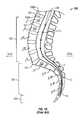
- the spine 120also known as the vertebral column or the spinal column, is a flexible column of vertebrae 100 (special types of bones) held together by muscles, ligaments and tendons.
- the spine 120extends from the cranium (not shown) to the coccyx 126 , encasing a spinal cord 128 and forming the supporting axis of the body (not shown).
- the spinal cord 128is a thick bundle of nerve tissue (nerves) that branch off to various areas of the body for the purposes of motor control, sensation, and the like.
- the spine 120includes seven cervical vertebrae (not shown), twelve thoracic vertebrae (not shown), five lumbar vertebrae, L I -L V , five sacral vertebrae, S I -S V , and three coccyx vertebrae 126 .
- the sacral and coccyx vertebraeare each fused, thereby functioning as a single unit.
- FIG. 10shows the lumbar region 122 , the sacral region 124 and the coccyx 126 of the spine 120 and that the vertebrae 100 are stacked one upon another.
- the top portion 100 a and bottom portion 100 b of each vertebrae 100is slightly concave.
- the opposing concave vertebral surfacesform the intervertebral space 121 in which an intervertebral disk (not shown) resides.
- Each of the intervertebral diskshas a soft core referred to as a nucleus pulposus or nucleus (not shown).
- each vertebrae 100includes a body 106 in the innermost portion, a spinal canal 108 and a spinous process 102 at the posterior-most end of the vertebra 100 .
- the vertebrae 100are substantially similar in composition, but vary in size from the larger lumbar vertebrae to the smallest coccyx vertebrae 126 .
- Each vertebrae 100further includes two transverse processes 104 located on either side and a protective plate-like structure referred to as a lamina 110 . Nerves from the spinal cord 128 pass through the spinal canal 108 and foramina 111 to reach their respective destinations within the body.
- the natural aging processcan cause a deterioration of the intervertebral disks, and therefore, their intrinsic support strength and stability is diminished. Sudden movements may cause a disk to rupture or herniate. A herniation of the disk is primarily a problem when the nucleus pulposus protrudes or ruptures into the spinal canal 108 placing pressure on nerves which in turn causes spasms, tingling, numbness, and/or pain in one or more parts of the body, depending on the nerves involved.
- Surgical optionsinclude chemonucleolysis, laminectomy, diskectomy, microdiskectomy, and spinal fusion.
- Chemonucleolysisis the injection of an enzyme, such as chymopapain, into the disk to dissolve the protruding nucleus pulposus.
- the enzymeis a protein-digesting enzyme and is used to dissolve the disk material. Since the enzyme is essentially a tissue-dissolving agent, it is indiscriminate in the protein-based matter it dissolves. Should the enzyme be injected into the wrong place, or if there is a breach in the disk capsule that would allow the solution to enter the spinal canal or to contact nerve tissue or the like, the resultant damage to nerve tissue could not be reversed. Even worse, about half of the patients who receive chemonucleolysis treatments experience increased back pain and muscle spasms immediately after the injection and more than half have incapacitating back pain for durations up to three months after such treatments.
- a laminectomyis performed to decompress the spinal canal by open surgical techniques under general anesthesia.
- the lamina 110(the bone that curves around and covers the spinal canal 108 as shown in FIG. 9 ), and any disk tissue causing pressure on a nerve or the spinal canal 108 , are partially removed.
- This techniqueis highly invasive and traumatic to the body, and therefore requires an extended recovery time of about five weeks and a hospital stay of a few days.
- there are increased risks of future problemsdue to the removed portion of the lamina 110 which is no longer in place to support and protect the spinal canal 108 at the area where the surgery took place.
- vertebrae 100may shift due to the lack of support in the structure.
- simply removing the disk and parts of the vertebral boneis a short-term, pain-relieving corrective action but not a long-term solution.
- Diskectomyis a form of spinal surgery wherein part of an intervertebral disk is excised typically through open surgical techniques. Recently, less invasive techniques referred to as percutaneous diskectomy or microdiskectomy have been developed to reduce the surgical trauma to the patient. In microdiskectomy, a much smaller incision is made than in normal open surgeries. A small retractor, working channel or tube is inserted through the posterior muscles (not shown) to allow access to the damaged or herniated disk.
- Surgeonsutilize special surgical instruments modified to work in such small openings such as curettes, osteotomes, reamers, probes, retractors, forceps, and the like to cut and remove part of the disk while monitoring their technique using a microscope, a fluoroscope (real-time X-ray monitoring), and/or an endoscope (a miniature TV camera with associated viewing monitor). While this technique is much less invasive than conventional open surgeries, due to their design the instruments presently available tend to extend the length of time of the surgery and may cause possible damage to areas other than the herniated disk.
- a spinal fusionis a procedure that involves fusing together two or more vertebrae in the spine using bone grafts and sometimes using metal fixation with screws, plates or metal rods.
- the removal of a significant amount of disk material or numerous surgeriesoften increases the instability of the spine 120 thereby necessitating spinal fusion surgery.
- the fusion procedureis often used to correct kyphosis or scoliosis, in addition to those patients who require spine stabilization due to vertebral damage from ruptured disks, fractures, osteomyelitis, osteoarthritis or tumors, and the like. In a fusion procedure, a damaged disk may be completely removed.
- Parts of a bone from another part of the body, such as the pelvis,are harvested, and the bone parts or grafts are subsequently placed between the adjacent vertebrae 100 so that the adjacent vertebrae 100 grow together in a solid mass.
- the posterior lamina 110 and the centers of the vertebral bodies 106may both be cut. The surgery often involves consequential damage to the associated posterior ligaments, muscles and joints in addition to the removal of part or all of the lamina 110 .
- the source of the bonemay be the patient, (autologous or autograft bone) or a bone bank harvested from other individuals, i.e. allograft bone. While autologous bone is generally considered better for promoting fusion between the vertebrae, it also necessitates extra surgery to remove bone from the patient's body. As with any surgery, risks can include bleeding, infection, adverse reactions to drugs, and difficulty under anesthesia. Additionally, the site of the bone graft harvest may cause pain in addition to the pain the patient is already suffering due to the difficulties associated with the vertebrae 100 or disk.
- One prior art fusion cage devicedisclosed in U.S. Pat. No. 4,961,740 of Ray et al. (hereinafter “Ray”), is a large cylindrically shaped fusion cage that has a deep helical thread around the outer surface.
- laminectomiesmust be performed on each side of the overlying lamina in order to provide access for the large cylindrically shaped fusion cage and if the disk space has narrowed as a result of degeneration, a scissors jack-type spreader or hydraulically inflated bladder is inserted on each side and opened to allow access to the disk space.
- a pilot cutter and pilot rodare used to cut female bone threads through the opposing vertebral endplates prior to threading the fusion basket into the now threaded interdiskal bore. Obviously the surgery is lengthy, highly intrusive and traumatic, and as noted in the Ray specification takes several weeks for recovery.
- McKayOther prior art devices, disclosed in U.S. Pat. Nos. 5,702,449 and 6,039,762 of McKay (hereinafter, “McKay”), are cylindrically shaped spinal implants with perforations or apertures located through the outside walls. While the implants of McKay provide for a non-metal, bone graft substitute, they still require open surgical techniques for implantation due to their size and geometric shape.
- Implantswere used by Dr. Fernstrom in the 1960's including stainless steel spherical ball bearings (see “Spine Arthroplasty,” Spine Industry Analysis Series , Viscogliosi Bros., LLC, November 2001.).
- the present inventioncomprises a vertebral defect device.
- the vertebral defect deviceincludes a housing having a convexly tapered distal end, a convexly tapered proximal end, a top, a bottom, an anterior side, a posterior side and an outer surface having generally rounded edges thereby facilitating insertion into an intervertebral space between a pair of adjacent vertebrae.
- the length of the housing as measured from the distal end to the proximal endis greater than the width of the housing as measured between the anterior and posterior sides and is greater than the height of the housing as measured between the top and bottom.
- the present inventionfurther comprises a vertebral defect device.
- the vertebral defect deviceincludes a housing, an upper shelf and a lower shelf.
- the housinghas a convexly tapered distal end, a convexly tapered proximal end, a top having a first opening to encourage vertebral fusion, a bottom having a second opening to encourage vertebral fusion, and an outer surface that is generally smooth thereby facilitating insertion into an intervertebral space between a pair of adjacent vertebrae.
- the upper shelfis disposed within the housing and is generally proximate to the first opening.
- the lower shelfis disposed within the housing and is generally proximate to the second opening.
- FIG. 1is a perspective view of a first preferred embodiment of a vertebral defect device in accordance with the present invention
- FIG. 2is a side elevational view of the vertebral defect device of FIG. 1 ;
- FIG. 3is a front elevational view of the vertebral defect device of FIG. 1 ;
- FIG. 4is a top plan view of the vertebral defect device of FIG. 1 ;
- FIG. 5is a side elevational view of a second preferred embodiment of a vertebral defect device in accordance with present invention.
- FIGS. 6A-6Bare side elevational views of a third preferred embodiment of a vertebral defect device in accordance with present invention.
- FIG. 7is a side elevational view of the vertebral defect device of FIG. 1 connected to a first preferred embodiment of an insertion tool in accordance with present invention
- FIG. 8is a side view of the vertebral defect device of FIG. 1 installed between lumbar vertebrae L III and L IV ;
- FIG. 9is a top sectional view of a human vertebra as is known in the art.
- FIG. 10is a side sectional view of a portion of a human spine as is known in the art.
- FIG. 11is a side elevational view of a fourth preferred embodiment of a vertebral defect device in accordance with the present invention.
- FIG. 12is a top plan view of the vertebral defect device of FIG. 11 ;
- FIG. 13Ais a side elevational view of a fifth preferred embodiment of a vertebral defect device in accordance with the present invention.
- FIG. 13Bis a top plan view of the vertebral defect device of FIG. 13A ;
- FIG. 14Ais a side elevational view of a second preferred embodiment of an insertion tool for a vertebral defect device in accordance with the present invention.
- FIG. 14Bis a top plan view of the insertion tool of FIG. 14A ;
- FIG. 15Ais a side elevational view of a third preferred embodiment of an insertion tool for a vertebral defect device in accordance with the present invention.
- FIG. 15Bis a top plan view of the insertion tool of FIG. 15A ;
- FIG. 16Ais a side elevational view of a fourth preferred embodiment of an insertion tool for a vertebral defect device in accordance with the present invention.
- FIG. 16Bis a top plan view of the insertion tool of FIG. 16A .
- vertebral defect deviceas used herein may be applicable to a fusion cage device, a partial disk replacement device or a nuclear replacement device without departing from the present invention, and should be construed to broadly encompass any device for use in correcting defects in the spine.
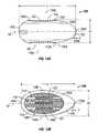
- FIG. 1a vertebral defect device 10 in accordance with a first preferred embodiment of the present invention.
- the vertebral defect device 10has a housing, a convexly-tapered distal end 10 a , a convexly-tapered proximal end 10 b , a lower wall 10 c , an upper wall 10 d , a first sidewall 10 e , and a second sidewall 10 f ( FIGS. 3 , 4 ).
- An outer surface 12is substantially smooth over the entire surface.
- the vertebral defect device 10may be titanium, or any metal or alloy compatible with MRI scanners, synthetic or polymeric materials, composites, ceramic, a biocompatible polymeric material, any biologically absorbable material and the like without departing from the broad inventive scope of the present invention.
- the vertebral defect device 10is generally lens-shaped or ovoid-shaped with rounded or contoured edges on all sides.
- the proximal end 10 bpreferably is rounded but more bluntly-shaped than the distal end 10 a which preferably is sloped into a bullet-shaped tip.
- the proximal end 10 bis preferably generally ovoid-shaped.
- the distal end 10 ahas a lesser average radius of curvature than the proximal end 10 b .
- the lower wall 10 c and upper wall 10 dpreferably are generally convex in order to cooperatively mate within the natural concavities of adjacent vertebral bodies 100 .
- first sidewall 10 e and second sidewall 10 f of the vertebral defect device 10preferably are similarly convex for similar reasons and to facilitate installation of the vertebral defect device 10 into an intervertebral space 121 .
- the shape of the vertebral defect device 10is ideally suited for insertion through a small opening, and therefore, the vertebral defect device 10 is well suited for minimally invasive and/or outpatient procedures.
- apertures 11Distributed evenly about the surface 12 of the vertebral defect device 10 are perforations or apertures 11 .
- the apertures 11are intended to promote rapid bone ingrowth while the vertebral defect device 10 maintains a stiff support structure between the vertebrae 100 during the growth process. While in the presently preferred embodiment, the apertures 11 are shown as circular in shape, the apertures 11 could be any shape including ovals, squares, rectangles, triangles, diamonds, crosses, X-shapes, and the like without departing from the spirit and scope of the invention. But, there need not be apertures 11 .
- the lower wall 10 cdefines a lower opening 16 a and the upper wall 10 d of the vertebral defect device 10 defines an upper opening 16 b at the point of vertebral contact to encourage successful fusion.
- the lower opening 16 a and the upper opening 16 bmay be rectangular, circular, elliptical, or the like and may or may not be symmetrically-shaped.
- the openings 16 a , 16 bare preferably identically-shaped with respect to one another and are preferably symmetrically-shaped, but need not be. Further, the size of openings 16 a and 16 b may be varied to accommodate patient variations.
- the length of the vertebral defect device as measured from the distal end 10 a to the proximal end 10 bpreferably is approximately 10-30 mm, depending on the particular intervertebral space 121 in which the vertebral defect device 10 is to be inserted.
- the intervertebral space between lumbar vertebra L III and lumbar vertebra L IV for an average malewould accommodate a vertebral defect device 10 of a length between approximately 25-30 mm.
- the length of the vertebral defect device 10could vary from the aforementioned range without departing from the spirit of the invention.
- the width of the vertebral defect device 10 as measured between the first sidewall 10 e and the second sidewall 10 f of the vertebral defect device 10will vary from approximately 10 mm to 25 mm depending upon the particular intervertebral space 121 in which the vertebral defect device 10 is to be inserted.
- the intervertebral space between vertebra L III and vertebra L IV in an average malewould accommodate a vertebral defect device 10 having a width of approximately 15-20 mm.
- the width of the vertebral defect device 10could vary from the aforementioned range without departing from the spirit of the invention.
- the height of the vertebral defect device 10 as measured between the upper wall 10 d and the lower wall 10 c of the vertebral defect device 10will vary from approximately 5 mm to 25 mm depending upon the particular intervertebral space 121 in which the vertebral defect device 10 is to be inserted.
- the intervertebral space between vertebra L III and vertebra L IV in an average malewould accommodate a vertebral defect device 10 having a height of approximately 8-16 mm.
- the height of the vertebral defect device 10could vary from the aforementioned range without departing from the spirit of the invention.
- the overall shape of the vertebral defect device 10is designed for insertion using minimally invasive techniques through a special portal or channel allowing a procedure to be implemented on an outpatient basis. Further, the vertebral defect device 10 is a self centering device because the shape of the vertebral defect device 10 will encourage it to settle within the natural concavities of adjacent vertebral bodies 100 . As such, placement of the vertebral defect device 10 is much faster than that of prior art devices, thereby effectively reducing the duration of a procedure and the associated risks therewith.
- the smooth contour and edges of the vertebral defect device 10provide for a safe and easy entrance into the intervertebral space 121 .
- the convex, bullet-like shape of the distal end 10 a of the vertebral defect device 10will allow it to be driven into the intervertebral space by merely temporarily distracting the vertebrae with minimal removal of the vertebral rim or annulus (not shown clearly) at the point of entry, thereby reducing the chance of dislodging the device post-surgery.
- the self-centering feature of the vertebral defect device 10will allow rapid settling of the vertebral defect device 10 into adjacent bone to promote rapid bone ingrowth while retention of most of the annulus and peripheral rim of the bodies (vertebrae) would provide good load sharing support to prevent excessive subsidence, where subsidence results from the natural settling of intervertebral matter into a softer central portion of the vertebral bodies 108 .
- FIG. 7shows the vertebral defect device 10 of the first preferred embodiment with a first preferred embodiment of a specially designed insertion tool 20 .
- the insertion tool 20is threaded into a socket 14 in the proximal end of the vertebral defect device 10 .
- the socket 14is provided with female threads 14 a which are configured to accept the male threads 20 a of the insertion tool 20 .
- the insertion tool 20may be formed of any substantially rigid material, but preferably is formed of a material that is bio-compatible such as titanium, stainless steel, nickel, or of a bio-compatible alloy, composite, polymeric material or the like. It should be noted that the material of construction of the insertion tool could be any material without diverging from the broad scope of the present invention. It is also contemplated that the insertion tool 20 and vertebral defect device 10 may be releasably coupled by any of several releasable fastening mechanisms known to those skilled in the art.
- FIGS. 14A-14Bshow a second preferred embodiment of an insertion tool 200 for a vertebral defect device 10 , 70 , 80 , 90 , or 190 in accordance with the present invention.
- the insertion tool 200has an elongate handle 202 and a grip 204 .
- the grip 204may be a suction cup or other similar gripping-type mechanism.
- FIG. 8shows a side view of the lumbar region 122 of a portion of a human spine 120 .
- a vertebral defect device 10 in accordance with the first preferred embodiment of the present inventionis shown installed between lumbar vertebra L III and lumbar vertebra L IV .
- the second sidewall 10 f of the vertebral defect device 10is placed on the anterior side of the L III -L IV intervertebral space
- the first sidewall 10 e of the vertebral defect device 10is placed closest to the posterior side of the L III -L IV intervertebral space
- the upper wall 10 d of the vertebral defect device 10is adjacent to vertebra L III
- the lower wall 10 c of the vertebral defect device 10is adjacent to vertebra L IV .
- the surgeonwould have inserted the distal end 10 a of the vertebral defect device 10 into the gap between the L III -L IV vertebrae as depicted in FIG. 9 by a directional arrow D. It is just as likely and possible for the surgeon to place the distal end 10 a of the vertebral defect device 10 through the space between the L III -L IV vertebrae in the direction of a directional arrow C ( FIG. 9 ) or from other directions.
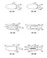
- FIG. 5shows a side elevational view of a second preferred embodiment of a vertebral defect device 70 in accordance with the present invention.
- the intervertebral defect device or vertebral defect device 70has a distal end 70 a , a proximal end 70 b , a lower wall 70 c , an upper wall 70 d , a first sidewall 70 e , and a second sidewall (not shown).
- An outer surface 72differs from the first preferred embodiment only in that the outer surface 72 of the vertebral defect device 70 is a lattice-type structure, instead of the body having a plurality of apertures 11 , but the outer surface 72 is also substantially smooth with rounded edges and can be made from similar materials as described with reference to the first preferred embodiment.
- the lower wall 70 cdefines a lower opening 76 a and the upper wall 70 d defines an upper opening 76 b at the point of vertebral contact to encourage successful fusion.
- FIGS. 6A-6Bshow a third preferred embodiment of a vertebral defect device 80 in accordance with the present invention.
- FIG. 6Ashows that the vertebral defect device 80 has a distal end 80 a , a proximal end 80 b , a lower wall 80 c , an upper wall 80 d , a first sidewall 80 e , and a second sidewall (not shown).
- the vertebral defect device 80further has an outer surface 82 , which in the present embodiment, is substantially smooth and free from apertures, openings, and the like.
- the presently preferred embodimentis ideally suited for use as a disk prosthesis or nuclear replacement-type device due to the lack of openings.
- the vertebral defect device 80out of a material that would not encourage adhesion or bone or tissue growth.
- the lower wall 80 cdefines a lower opening 86 a and the upper wall 80 d defines an upper opening 86 b for intervertebral contact to encourage successful fusion.
- FIGS. 11 and 12show a fourth preferred embodiment of a vertebral defect device 90 in accordance with the present invention.
- the vertebral defect device 90has a distal end 90 a , a proximal end 90 b , a lower wall 90 c , an upper wall 90 d , a first sidewall 90 e , and a second sidewall 90 f .
- the vertebral defect device 90further has an outer surface 92 , which in the present embodiment, is substantially smooth and free from apertures, openings, and the like, but may have apertures without departing from the present invention.
- the lower wall 90 cdefines a lower opening 96 a and the upper wall 90 d defines an upper opening 96 b for intervertebral contact to encourage successful fusion.
- the vertebral defect device 90further includes a lower grating 98 a and an upper grating 98 b .
- the gratings 98 a , 98 bare formed of a substantially rigid mesh that is coated with a bio-compatible ceramic to promote bone growth.
- the gratings 98 a , 98 bare located slightly below an outer edge defined by the openings 96 a , 96 b in order to allow some or partial subsidence of the vertebrae 100 partially into the vertebral defect device 90 , but will prevent excessive subsidence.
- the gratings 98 a , 98 bare merely recessed portions of the lower wall 90 c and upper wall 90 d having perforations, apertures or slits which allow bone ingrowth.
- FIGS. 13A and 13Bshow a fifth preferred embodiment of a vertebral defect device 190 in accordance with the present invention.
- the vertebral defect device 190has a distal end 190 a , a proximal end 190 b , a lower wall 190 c , an upper wall 190 d , a first sidewall 190 e , and a second sidewall 190 f .
- the vertebral defect device 190further has an outer surface 192 , which in the present embodiment, is substantially smooth and free from apertures, openings, and the like, but may have apertures without departing from the present invention.
- the lower wall 190 cdefines a lower opening 196 a and the upper wall 190 d defines an upper opening 196 b for intervertebral contact to encourage successful fusion.
- the vertebral defect device 190further includes a lower grating 198 a and an upper grating 198 b .
- the gratings 198 a , 198 bare formed of a substantially rigid mesh that is coated with a bio-compatible ceramic to promote bone growth.
- the gratings 198 a , 198 bare located slightly below an outer edge defined by the openings 196 a , 196 b in order to allow some subsidence of the vertebrae 100 partially into the vertebral defect device 190 , but will prevent excessive subsidence.
- the vertebral defect device 190includes at least one upper arch 150 and at least one lower arch 152 , but preferably the vertebral defect device 190 includes three upper arches 150 and three lower arches 152 .
- the arches 150 , 152are generally disposed symmetrically along and about a centerline of the longer axis of the vertebral defect device 190 and are secured to the body of the vertebral defect device 190 .
- the arches 150 , 152may be secured to the vertebral defect device 190 by other means and may be disposed in other orientations without departing from the spirit of the present invention.
- the arches 150 , 152protrude above the top and bottom 190 d , 190 c of the vertebral defect device 190 , respectively.
- the arches 150 , 152are configured to settle into bone matter, and therefore, the arches 150 , 152 have sharpened edges 150 a , 152 a .
- the sharpened edges 150 a , 152 amay include serrations, pins, sharpened cones or a simple knife-like edge, but need not be.
- the sharpened edges 150 a , 152 aare partially knife like proximate the ends of the arches and partially covered with sharpened cones 153 .
- the arches 150 , 152are preferably about 0.5 mm to about 2.0 mm wide.
- the arches 150 , 152also serve to center the vertebral defect device 190 during placement and prevent the vertebral defect device from rolling or canting thereafter.
- arches 150 , 152could be utilized in any of the embodiments of the vertebral defect devices 10 , 70 , 80 , 90 , or 190 , as described herein.
- FIGS. 15A-15Bshow a third preferred embodiment of an insertion tool 220 for a vertebral defect device 10 ( 70 , 80 , or 90 ) having upper and lower openings 16 a , 16 b ( 76 a , 76 b , 86 a , 86 b , 96 a , 96 b ).
- the insertion tool 220has a first finger 222 configured to cooperatively engage the upper opening 16 a and a second finger 224 configured to cooperatively engage the lower opening 16 b.
- the fingers 222 , 224have outer surfaces which are shaped to match the contoured shape of the vertebral defect device 10 to allow a smooth insertion of the vertebral defect device 10 .
- the fingers 222 , 224also prevent foreign matter and debris from getting caught in the openings 16 a , 16 b during insertion. Because the fingers 222 , 224 grasp the vertebral defect device 10 in a specific orientation defined by the upper and lower openings 16 a , 16 b , the insertion tool 220 provides the surgeon with means to orient the vertebral defect device 10 correctly during insertion.
- the insertion tool 220further includes a driving member 226 that is configured to engage the body of the vertebral defect device 10 .
- the driving member 226is configured to be impacted such that during insertion a surgeon may tap or hammer the driving member 226 to push the vertebral defect device 10 through a small opening.
- the first and second fingers 222 , 224are retractable relative to the driving member 226 .
- the vertebral defect device 10may have grooves 166 (shown in phantom in FIG. 15B ) extending from the upper and lower openings 16 a , 16 b to facilitate the removal of the retractable fingers 222 , 224 .
- FIGS. 16A-16Bis a side elevational view of a fourth preferred embodiment of an insertion tool 230 for a vertebral defect device 190 having upper and lower openings 196 a , 196 b and upper and lower arches 150 , 152 .
- the upper finger 232has first and second prongs 232 a , 232 b for straddling the upper arch 150 as best seen in FIG. 16B .
- the insertion tool 230is similar to the insertion tool 220 , but each of the retractable fingers 232 234 is forked to accommodate the arches 150 , 152 .
- the arches 150 , 152are just below the outer surface of the fingers 232 , 234 , so that the arches 150 , 152 do not injure adjacent tissue during insertion. Furthermore, it would be obvious to one skilled in the art to utilize multiple prongs 232 a , 232 b in each of the retractable fingers 232 , 234 in order to accommodate multiple arches 150 , 152 .
- the vertebral defect device 10has a maximum height H and/or maximum width W, preferably in the range of 6 to 15 mm, at an axial location intermediate the distal end 10 a and the proximal end 10 b .
- the vertebral defect device 10has a length L, preferably in the range of 10 to 30 mm, along a longitudinal axis 42 .
- An outer profile of the vertebral defect device 10is characterized by a relatively gradual slope, such that the diameter (height and width) of the vertebral defect device 10 preferably changes no more than about 2 mm for every 1 mm change in length.
- the distal end 10 ain particular, has a slope that changes by no more than about 2 mm for every 1 mm change in length.
- the distal end 10 ais preferably relatively small, for example, less than 2.5 mm in diameter over the terminal 1 mm T of the distal end 10 a along the longitudinal axis 42 or approximately 5-20% of the maximum height H and/or maximum width W of the vertebral defect device 10 .
- the distal end 10 ashould not be so pointed such that it would easily drive through or penetrate the opposite side of the annulus on the opposite side of the disk space.
- the taper and slope of the distal end 10 a of the vertebral defect device 10permit the vertebral defect device 10 to be at least partially self-distracting.
- the vertebral defect device 10is intended to be impacted into the disk space while providing such distraction of the periphery of the vertebral bodies 100 to permit entry into nuclear center of the disk.
- the vertebral defect device 10may be dimensioned in accordance with the requirements of specific applications, and other dimensional characteristics of the vertebral defect device 10 are included within the scope of this invention.
Landscapes
- Health & Medical Sciences (AREA)
- Engineering & Computer Science (AREA)
- Biomedical Technology (AREA)
- Orthopedic Medicine & Surgery (AREA)
- Transplantation (AREA)
- Neurology (AREA)
- Oral & Maxillofacial Surgery (AREA)
- Cardiology (AREA)
- Heart & Thoracic Surgery (AREA)
- Vascular Medicine (AREA)
- Life Sciences & Earth Sciences (AREA)
- Animal Behavior & Ethology (AREA)
- General Health & Medical Sciences (AREA)
- Public Health (AREA)
- Veterinary Medicine (AREA)
- Physical Education & Sports Medicine (AREA)
- Prostheses (AREA)
Abstract
Description
Claims (3)
Priority Applications (3)
| Application Number | Priority Date | Filing Date | Title |
|---|---|---|---|
| US11/463,056US7674295B2 (en) | 2002-01-17 | 2006-08-08 | Vertebral defect device |
| US12/141,702US8137402B2 (en) | 2002-01-17 | 2008-06-18 | Vertebral defect device |
| US12/643,693US8167886B2 (en) | 2002-01-17 | 2009-12-21 | Insertion tool for a vertebral defect device |
Applications Claiming Priority (5)
| Application Number | Priority Date | Filing Date | Title |
|---|---|---|---|
| US34973002P | 2002-01-17 | 2002-01-17 | |
| US36951002P | 2002-04-02 | 2002-04-02 | |
| US10/345,591US7105023B2 (en) | 2002-01-17 | 2003-01-16 | Vertebral defect device |
| US10/988,830US7534267B2 (en) | 2002-01-17 | 2004-11-15 | Methods of installing a vertebral defect device |
| US11/463,056US7674295B2 (en) | 2002-01-17 | 2006-08-08 | Vertebral defect device |
Related Parent Applications (2)
| Application Number | Title | Priority Date | Filing Date |
|---|---|---|---|
| US10/988,830Continuation-In-PartUS7534267B2 (en) | 2002-01-17 | 2004-11-15 | Methods of installing a vertebral defect device |
| US10/988,830DivisionUS7534267B2 (en) | 2002-01-17 | 2004-11-15 | Methods of installing a vertebral defect device |
Related Child Applications (2)
| Application Number | Title | Priority Date | Filing Date |
|---|---|---|---|
| US12/141,702Continuation-In-PartUS8137402B2 (en) | 2002-01-17 | 2008-06-18 | Vertebral defect device |
| US12/643,693DivisionUS8167886B2 (en) | 2002-01-17 | 2009-12-21 | Insertion tool for a vertebral defect device |
Publications (2)
| Publication Number | Publication Date |
|---|---|
| US20070016299A1 US20070016299A1 (en) | 2007-01-18 |
| US7674295B2true US7674295B2 (en) | 2010-03-09 |
Family
ID=27616748
Family Applications (4)
| Application Number | Title | Priority Date | Filing Date |
|---|---|---|---|
| US10/345,591Expired - LifetimeUS7105023B2 (en) | 2002-01-17 | 2003-01-16 | Vertebral defect device |
| US10/988,830Expired - LifetimeUS7534267B2 (en) | 2002-01-17 | 2004-11-15 | Methods of installing a vertebral defect device |
| US11/463,056Expired - Fee RelatedUS7674295B2 (en) | 2002-01-17 | 2006-08-08 | Vertebral defect device |
| US12/643,693Expired - Fee RelatedUS8167886B2 (en) | 2002-01-17 | 2009-12-21 | Insertion tool for a vertebral defect device |
Family Applications Before (2)
| Application Number | Title | Priority Date | Filing Date |
|---|---|---|---|
| US10/345,591Expired - LifetimeUS7105023B2 (en) | 2002-01-17 | 2003-01-16 | Vertebral defect device |
| US10/988,830Expired - LifetimeUS7534267B2 (en) | 2002-01-17 | 2004-11-15 | Methods of installing a vertebral defect device |
Family Applications After (1)
| Application Number | Title | Priority Date | Filing Date |
|---|---|---|---|
| US12/643,693Expired - Fee RelatedUS8167886B2 (en) | 2002-01-17 | 2009-12-21 | Insertion tool for a vertebral defect device |
Country Status (4)
| Country | Link |
|---|---|
| US (4) | US7105023B2 (en) |
| EP (1) | EP1471854A4 (en) |
| JP (1) | JP2005515024A (en) |
| WO (1) | WO2003061533A1 (en) |
Cited By (8)
| Publication number | Priority date | Publication date | Assignee | Title |
|---|---|---|---|---|
| US20090248163A1 (en)* | 2008-03-31 | 2009-10-01 | King Emily E | Spinal surgery interbody |
| US20100161056A1 (en)* | 2008-12-19 | 2010-06-24 | Depuy Spine, Inc. | Methods and devices for expanding a spinal canal |
| US20120330360A1 (en)* | 2010-03-09 | 2012-12-27 | National University Corporation Kobe University | Inter-spinous process implant |
| US9358122B2 (en) | 2011-01-07 | 2016-06-07 | K2M, Inc. | Interbody spacer |
| USD847339S1 (en) | 2017-06-26 | 2019-04-30 | Advanced Research System, LLC | Spinal fusion cage |
| USD879295S1 (en) | 2017-02-13 | 2020-03-24 | Advance Research System, Llc | Spinal fusion cage |
| US11058551B2 (en) | 2016-12-16 | 2021-07-13 | Advance Research System, Llc | Interbody implant with concave profiled nose |
| US11737888B1 (en) | 2019-09-19 | 2023-08-29 | Advance Research System, Llc | Spinal fusion implant system and method |
Families Citing this family (73)
| Publication number | Priority date | Publication date | Assignee | Title |
|---|---|---|---|---|
| FR2767675B1 (en)* | 1997-08-26 | 1999-12-03 | Materiel Orthopedique En Abreg | INTERSOMATIC IMPLANT AND ANCILLARY OF PREPARATION SUITABLE FOR ALLOWING ITS POSITION |
| US7717961B2 (en) | 1999-08-18 | 2010-05-18 | Intrinsic Therapeutics, Inc. | Apparatus delivery in an intervertebral disc |
| US7972337B2 (en) | 2005-12-28 | 2011-07-05 | Intrinsic Therapeutics, Inc. | Devices and methods for bone anchoring |
| CA2425951C (en) | 1999-08-18 | 2008-09-16 | Intrinsic Therapeutics, Inc. | Devices and method for nucleus pulposus augmentation and retention |
| US7998213B2 (en) | 1999-08-18 | 2011-08-16 | Intrinsic Therapeutics, Inc. | Intervertebral disc herniation repair |
| US8323341B2 (en) | 2007-09-07 | 2012-12-04 | Intrinsic Therapeutics, Inc. | Impaction grafting for vertebral fusion |
| EP1624832A4 (en) | 1999-08-18 | 2008-12-24 | Intrinsic Therapeutics Inc | Devices and method for augmenting a vertebral disc nucleus |
| US7094258B2 (en) | 1999-08-18 | 2006-08-22 | Intrinsic Therapeutics, Inc. | Methods of reinforcing an annulus fibrosis |
| US7169183B2 (en)* | 2000-03-14 | 2007-01-30 | Warsaw Orthopedic, Inc. | Vertebral implant for promoting arthrodesis of the spine |
| FR2824261B1 (en) | 2001-05-04 | 2004-05-28 | Ldr Medical | INTERVERTEBRAL DISC PROSTHESIS AND IMPLEMENTATION METHOD AND TOOLS |
| US8388684B2 (en) | 2002-05-23 | 2013-03-05 | Pioneer Signal Technology, Inc. | Artificial disc device |
| US7001433B2 (en) | 2002-05-23 | 2006-02-21 | Pioneer Laboratories, Inc. | Artificial intervertebral disc device |
| US7063725B2 (en)* | 2002-10-21 | 2006-06-20 | Sdgi Holdings, Inc. | Systems and techniques for restoring and maintaining intervertebral anatomy |
| US7125425B2 (en)* | 2002-10-21 | 2006-10-24 | Sdgi Holdings, Inc. | Systems and techniques for restoring and maintaining intervertebral anatomy |
| FR2846550B1 (en) | 2002-11-05 | 2006-01-13 | Ldr Medical | INTERVERTEBRAL DISC PROSTHESIS |
| US20040215189A1 (en)* | 2003-04-23 | 2004-10-28 | Kung-Chia Li | Pedicle augmenter for vertebral body reconstruction |
| EP2113227B1 (en) | 2004-02-04 | 2015-07-29 | LDR Medical | Intervertebral disc prosthesis |
| FR2865629B1 (en) | 2004-02-04 | 2007-01-26 | Ldr Medical | INTERVERTEBRAL DISC PROSTHESIS |
| FR2869528B1 (en) | 2004-04-28 | 2007-02-02 | Ldr Medical | INTERVERTEBRAL DISC PROSTHESIS |
| US8021392B2 (en) | 2004-11-22 | 2011-09-20 | Minsurg International, Inc. | Methods and surgical kits for minimally-invasive facet joint fusion |
| US20060111780A1 (en) | 2004-11-22 | 2006-05-25 | Orthopedic Development Corporation | Minimally invasive facet joint hemi-arthroplasty |
| US20060111779A1 (en) | 2004-11-22 | 2006-05-25 | Orthopedic Development Corporation, A Florida Corporation | Minimally invasive facet joint fusion |
| FR2879436B1 (en) | 2004-12-22 | 2007-03-09 | Ldr Medical | INTERVERTEBRAL DISC PROSTHESIS |
| US8083798B2 (en)* | 2005-04-04 | 2011-12-27 | Warsaw Orthopedic, Inc. | Non-circular stabilization sphere and method |
| US7959675B2 (en)* | 2005-04-08 | 2011-06-14 | G&L Consulting, Llc | Spine implant insertion device and method |
| FR2887762B1 (en) | 2005-06-29 | 2007-10-12 | Ldr Medical Soc Par Actions Si | INTERVERTEBRAL DISC PROSTHESIS INSERTION INSTRUMENTATION BETWEEN VERTEBRATES |
| US20090054987A1 (en)* | 2005-07-05 | 2009-02-26 | Spinefrontier Lls | Spinal fusion assembly |
| FR2891135B1 (en) | 2005-09-23 | 2008-09-12 | Ldr Medical Sarl | INTERVERTEBRAL DISC PROSTHESIS |
| US20070088436A1 (en)* | 2005-09-29 | 2007-04-19 | Matthew Parsons | Methods and devices for stenting or tamping a fractured vertebral body |
| FR2893838B1 (en) | 2005-11-30 | 2008-08-08 | Ldr Medical Soc Par Actions Si | PROSTHESIS OF INTERVERTEBRAL DISC AND INSTRUMENTATION OF INSERTION OF THE PROSTHESIS BETWEEN VERTEBRATES |
| WO2007075411A2 (en)* | 2005-12-16 | 2007-07-05 | Thomas Haider Patents, A Limited Liability Company | An intervertebral prosthesis for supporting adjacent vertebral bodies enabling the creation of soft fusion and method |
| US7559930B2 (en)* | 2006-01-26 | 2009-07-14 | Warsaw Orthopedic, Inc. | Surgical tool and method with an actuation mechanism for controlling reciprocation and locking of an anti-rotation member relative to an engagement member for facilitating positioning of an intervertebral device |
| US8409290B2 (en)* | 2006-03-08 | 2013-04-02 | Seaspine, Inc. | Interbody device for spinal applications |
| WO2008034135A2 (en) | 2006-09-15 | 2008-03-20 | Pioneer Surgical Technology, Inc. | Joint arthroplasty devices having articulating members |
| US8715350B2 (en) | 2006-09-15 | 2014-05-06 | Pioneer Surgical Technology, Inc. | Systems and methods for securing an implant in intervertebral space |
| US8641764B2 (en)* | 2006-10-11 | 2014-02-04 | G&L Consulting, Llc | Spine implant insertion device and method |
| US20080140085A1 (en)* | 2006-12-11 | 2008-06-12 | G&L Consulting, Llc | Steerable spine implant insertion device and method |
| US8097037B2 (en)* | 2006-12-20 | 2012-01-17 | Depuy Spine, Inc. | Methods and devices for correcting spinal deformities |
| US20080177389A1 (en)* | 2006-12-21 | 2008-07-24 | Rob Gene Parrish | Intervertebral disc spacer |
| US8465546B2 (en) | 2007-02-16 | 2013-06-18 | Ldr Medical | Intervertebral disc prosthesis insertion assemblies |
| US20090048675A1 (en)* | 2007-04-25 | 2009-02-19 | Bhatnagar Mohit K | Spinal Fusion Implants with Selectively Applied Bone Growth Promoting Agent |
| US8241357B2 (en)* | 2007-04-25 | 2012-08-14 | Jmea Corporation | Prosthesis with a selectively applied bone growth promoting agent |
| US8257395B2 (en)* | 2007-09-21 | 2012-09-04 | Jmea Corporation | Spinal fixation with selectively applied bone growth promoting agent |
| FR2916956B1 (en) | 2007-06-08 | 2012-12-14 | Ldr Medical | INTERSOMATIC CAGE, INTERVERTEBRAL PROSTHESIS, ANCHORING DEVICE AND IMPLANTATION INSTRUMENTATION |
| US20110060366A1 (en)* | 2007-06-29 | 2011-03-10 | Stephen Heim | Facet Joint Implant and Related Methods |
| US20110196492A1 (en) | 2007-09-07 | 2011-08-11 | Intrinsic Therapeutics, Inc. | Bone anchoring systems |
| US20090088855A1 (en)* | 2007-09-27 | 2009-04-02 | K2M, Inc. | Posterior rod capturing spacer device and method |
| WO2009100400A1 (en)* | 2008-02-06 | 2009-08-13 | Nuvasive, Inc. | Systems and methods for spinal fusion |
| US20110029087A1 (en)* | 2008-04-04 | 2011-02-03 | Haider Thomas T | Intervertebral prostheses with compliant filler material for supporting adjacent vertebral bodies and method |
| US8518113B2 (en)* | 2008-05-20 | 2013-08-27 | Warsaw Othopedic, Inc. | Intervertebral implant and methods of implantation and manufacture |
| USD853560S1 (en) | 2008-10-09 | 2019-07-09 | Nuvasive, Inc. | Spinal implant insertion device |
| US8906094B2 (en)* | 2008-12-31 | 2014-12-09 | Spineology, Inc. | System and method for performing percutaneous spinal interbody fusion |
| US20100247600A1 (en)* | 2009-03-24 | 2010-09-30 | Warsaw Orthopedic, Inc. | Therapeutic drug eluting implant cover and method of making the same |
| US9078712B2 (en) | 2009-04-15 | 2015-07-14 | Warsaw Orthopedic, Inc. | Preformed drug-eluting device to be affixed to an anterior spinal plate |
| US9414864B2 (en) | 2009-04-15 | 2016-08-16 | Warsaw Orthopedic, Inc. | Anterior spinal plate with preformed drug-eluting device affixed thereto |
| EP2547292B1 (en) | 2010-03-16 | 2019-04-24 | Pinnacle Spine Group, LLC | Ntervertebral implants and graft delivery systems |
| US9468535B2 (en)* | 2010-12-17 | 2016-10-18 | K2M, Inc. | Interbody spacer |
| US9380932B1 (en) | 2011-11-02 | 2016-07-05 | Pinnacle Spine Group, Llc | Retractor devices for minimally invasive access to the spine |
| US9198769B2 (en) | 2011-12-23 | 2015-12-01 | Pioneer Surgical Technology, Inc. | Bone anchor assembly, bone plate system, and method |
| WO2014159739A1 (en) | 2013-03-14 | 2014-10-02 | Pinnacle Spine Group, Llc | Interbody implants and graft delivery systems |
| US20160213405A1 (en) | 2015-01-27 | 2016-07-28 | K2M, Inc. | Vertebral plate systems and methods of use |
| US10028841B2 (en) | 2015-01-27 | 2018-07-24 | K2M, Inc. | Interbody spacer |
| CN108135709B (en)* | 2015-08-11 | 2020-06-16 | Sc医药公司 | A device for maintaining intervertebral space |
| CN105287061B (en)* | 2015-12-01 | 2017-08-25 | 四川大学华西医院 | Interface type interbody fusion cage |
| AU2016369593B2 (en) | 2015-12-16 | 2021-04-01 | Nuvasive, Inc. | Porous spinal fusion implant |
| US10512545B2 (en)* | 2016-10-24 | 2019-12-24 | Corelink, Llc | Interbody spacer for spinal fusion |
| EP3415108B1 (en) | 2017-05-25 | 2024-09-04 | Stryker European Operations Holdings LLC | Fusion cage with integrated fixation and insertion features |
| US11006981B2 (en) | 2017-07-07 | 2021-05-18 | K2M, Inc. | Surgical implant and methods of additive manufacturing |
| WO2019051260A1 (en) | 2017-09-08 | 2019-03-14 | Pioneer Surgical Technology, Inc. | Intervertebral implants, instruments, and methods |
| USD907771S1 (en) | 2017-10-09 | 2021-01-12 | Pioneer Surgical Technology, Inc. | Intervertebral implant |
| CN109009136B (en)* | 2018-08-30 | 2024-03-22 | 中国人民解放军第二军医大学第二附属医院 | Novel intervertebral measuring device |
| US11534307B2 (en) | 2019-09-16 | 2022-12-27 | K2M, Inc. | 3D printed cervical standalone implant |
| US11529149B2 (en) | 2019-09-20 | 2022-12-20 | Spineology Inc. | Percutaneous discectomy kit and method |
Citations (38)
| Publication number | Priority date | Publication date | Assignee | Title |
|---|---|---|---|---|
| US4349921A (en) | 1980-06-13 | 1982-09-21 | Kuntz J David | Intervertebral disc prosthesis |
| US4545374A (en) | 1982-09-03 | 1985-10-08 | Jacobson Robert E | Method and instruments for performing a percutaneous lumbar diskectomy |
| US4936848A (en) | 1989-09-22 | 1990-06-26 | Bagby George W | Implant for vertebrae |
| US4961740A (en) | 1988-10-17 | 1990-10-09 | Surgical Dynamics, Inc. | V-thread fusion cage and method of fusing a bone joint |
| US5258031A (en) | 1992-01-06 | 1993-11-02 | Danek Medical | Intervertebral disk arthroplasty |
| US5425773A (en) | 1992-01-06 | 1995-06-20 | Danek Medical, Inc. | Intervertebral disk arthroplasty device |
| US5522899A (en) | 1988-06-28 | 1996-06-04 | Sofamor Danek Properties, Inc. | Artificial spinal fusion implants |
| US5549679A (en) | 1994-05-20 | 1996-08-27 | Kuslich; Stephen D. | Expandable fabric implant for stabilizing the spinal motion segment |
| WO1996040014A1 (en) | 1995-06-07 | 1996-12-19 | Sdgi Holdings, Inc. | Reinforced porous spinal implants |
| USD377095S (en) | 1994-06-03 | 1996-12-31 | Sofamor Danek Properties, Inc. | Interbody spinal implant |
| USD377096S (en) | 1994-06-03 | 1996-12-31 | Sofamor Danek Properties, Inc. | Interbody spinal implant |
| US5593409A (en) | 1988-06-13 | 1997-01-14 | Sofamor Danek Group, Inc. | Interbody spinal fusion implants |
| USD377527S (en) | 1994-06-03 | 1997-01-21 | Sofamor Danek Group, Inc. | Artificial spinal infusion implant |
| US5609636A (en) | 1994-05-23 | 1997-03-11 | Spine-Tech, Inc. | Spinal implant |
| WO1997014377A1 (en) | 1995-10-16 | 1997-04-24 | Sdgi Holdings, Inc. | Intervertebral spacer |
| FR2742044A1 (en) | 1995-12-11 | 1997-06-13 | Medinov Sa | Spinal inter vertebral bone prosthesis |
| US5645596A (en) | 1993-07-07 | 1997-07-08 | Asahi Kogaku Kogyo Kabushiki Kaisha | Ceramic vertebrae prosthesis |
| US5653761A (en) | 1994-03-18 | 1997-08-05 | Pisharodi; Madhavan | Method of lumbar intervertebral disk stabilization |
| US5669909A (en) | 1995-03-27 | 1997-09-23 | Danek Medical, Inc. | Interbody fusion device and method for restoration of normal spinal anatomy |
| US5674296A (en) | 1994-11-14 | 1997-10-07 | Spinal Dynamics Corporation | Human spinal disc prosthesis |
| FR2762779A1 (en) | 1997-05-05 | 1998-11-06 | Valentin Riemens | ANATOMICAL CAGE FOR INTER VERTEBRAL SPACE |
| US5888226A (en) | 1997-11-12 | 1999-03-30 | Rogozinski; Chaim | Intervertebral prosthetic disc |
| WO1999032054A1 (en) | 1997-12-19 | 1999-07-01 | Sofamor Danek Holdings, Inc. | Partial discal prosthesis |
| US6039762A (en) | 1995-06-07 | 2000-03-21 | Sdgi Holdings, Inc. | Reinforced bone graft substitutes |
| USD425989S (en) | 1996-07-15 | 2000-05-30 | Sofamor Danek Holdings, Inc. | Artificial spinal fusion implant |
| US6113637A (en) | 1998-10-22 | 2000-09-05 | Sofamor Danek Holdings, Inc. | Artificial intervertebral joint permitting translational and rotational motion |
| US6136031A (en) | 1998-06-17 | 2000-10-24 | Surgical Dynamics, Inc. | Artificial intervertebral disc |
| FR2794967A1 (en) | 1999-06-21 | 2000-12-22 | Medicrea | Dilating device for insertion in bone joints, useful for joints affected by degenerative tissue disease, is shaped like a cone designed to fill the biconcave joint cavity |
| US6174334B1 (en) | 1998-12-16 | 2001-01-16 | Loubert Suddaby | Expandable intervertebral fusion implant and applicator |
| US6245108B1 (en) | 1999-02-25 | 2001-06-12 | Spineco | Spinal fusion implant |
| US6270528B1 (en) | 1998-08-06 | 2001-08-07 | Sdgi Holdings, Inc. | Composited intervertebral bone spacers |
| US20010018614A1 (en) | 1999-03-16 | 2001-08-30 | Bianchi John R. | Implants for orthopedic applications |
| US6419705B1 (en) | 1999-06-23 | 2002-07-16 | Sulzer Spine-Tech Inc. | Expandable fusion device and method |
| US6425920B1 (en) | 1999-10-13 | 2002-07-30 | James S. Hamada | Spinal fusion implant |
| US6454805B1 (en) | 1998-09-04 | 2002-09-24 | Dimso (Distribution Medicale Du Sud-Ouest) | Interbody cavity implant, in particular for cervical vertebrae |
| US6468311B2 (en) | 2001-01-22 | 2002-10-22 | Sdgi Holdings, Inc. | Modular interbody fusion implant |
| US6582433B2 (en) | 2001-04-09 | 2003-06-24 | St. Francis Medical Technologies, Inc. | Spine fixation device and method |
| EP1112753B1 (en) | 1999-12-30 | 2004-07-14 | Bioprofile | Mobile implant for interposition between two osseous surfaces |
Family Cites Families (32)
| Publication number | Priority date | Publication date | Assignee | Title |
|---|---|---|---|---|
| US588226A (en)* | 1897-08-17 | Car fender | ||
| GB2097594B (en) | 1981-04-29 | 1984-09-19 | Stromberg Greest Ltd | Receiver aerial |
| US6210412B1 (en) | 1988-06-13 | 2001-04-03 | Gary Karlin Michelson | Method for inserting frusto-conical interbody spinal fusion implants |
| US6923810B1 (en) | 1988-06-13 | 2005-08-02 | Gary Karlin Michelson | Frusto-conical interbody spinal fusion implants |
| US5484437A (en)* | 1988-06-13 | 1996-01-16 | Michelson; Gary K. | Apparatus and method of inserting spinal implants |
| US5609635A (en) | 1988-06-28 | 1997-03-11 | Michelson; Gary K. | Lordotic interbody spinal fusion implants |
| USD356129S (en) | 1993-08-09 | 1995-03-07 | Wolf Rodney A | Football |
| US6309421B1 (en) | 1994-03-18 | 2001-10-30 | Madhavan Pisharodi | Rotating, locking intervertebral disk stabilizer and applicator |
| US5980522A (en) | 1994-07-22 | 1999-11-09 | Koros; Tibor | Expandable spinal implants |
| DE69526094T2 (en) | 1994-09-15 | 2002-11-21 | Surgical Dynamics, Inc. | CONICAL FUSION CAGE |
| US5766252A (en) | 1995-01-24 | 1998-06-16 | Osteonics Corp. | Interbody spinal prosthetic implant and method |
| US6264684B1 (en) | 1995-03-10 | 2001-07-24 | Impra, Inc., A Subsidiary Of C.R. Bard, Inc. | Helically supported graft |
| WO1998017209A2 (en) | 1996-10-23 | 1998-04-30 | Sdgi Holdings, Inc. | Spinal spacer |
| AU744371B2 (en) | 1997-04-25 | 2002-02-21 | Stryker European Holdings I, Llc | Two-part intersomatic implant |
| US6193757B1 (en) | 1998-10-29 | 2001-02-27 | Sdgi Holdings, Inc. | Expandable intervertebral spacers |
| US6102950A (en) | 1999-01-19 | 2000-08-15 | Vaccaro; Alex | Intervertebral body fusion device |
| US6520991B2 (en) | 1999-05-11 | 2003-02-18 | Donald R. Huene | Expandable implant for inter-vertebral stabilization, and a method of stabilizing vertebrae |
| EP1099429A1 (en)* | 1999-11-09 | 2001-05-16 | Laciter Management Limited | Interbody Fusion cage with crescent shaped lips (duckbill shaped) |
| US6478800B1 (en) | 2000-05-08 | 2002-11-12 | Depuy Acromed, Inc. | Medical installation tool |
| US6730127B2 (en) | 2000-07-10 | 2004-05-04 | Gary K. Michelson | Flanged interbody spinal fusion implants |
| WO2002034170A2 (en) | 2000-10-24 | 2002-05-02 | Howmedica Osteonics Corp. | Barrel-shaped apparatus for fusing adjacent bone structure |
| US6478822B1 (en)* | 2001-03-20 | 2002-11-12 | Spineco, Inc. | Spherical spinal implant |
| US6558424B2 (en) | 2001-06-28 | 2003-05-06 | Depuy Acromed | Modular anatomic fusion device |
| US7156877B2 (en) | 2001-06-29 | 2007-01-02 | The Regents Of The University Of California | Biodegradable/bioactive nucleus pulposus implant and method for treating degenerated intervertebral discs |
| US6607558B2 (en) | 2001-07-03 | 2003-08-19 | Axiomed Spine Corporation | Artificial disc |
| US6648917B2 (en) | 2001-10-17 | 2003-11-18 | Medicinelodge, Inc. | Adjustable bone fusion implant and method |
| US7011684B2 (en) | 2002-01-17 | 2006-03-14 | Concept Matrix, Llc | Intervertebral disk prosthesis |
| AU2003286531A1 (en) | 2002-10-21 | 2004-05-13 | 3Hbfm, Llc | Intervertebral disk prosthesis |
| US7125425B2 (en) | 2002-10-21 | 2006-10-24 | Sdgi Holdings, Inc. | Systems and techniques for restoring and maintaining intervertebral anatomy |
| US7112222B2 (en) | 2003-03-31 | 2006-09-26 | Depuy Spine, Inc. | Anterior lumbar interbody fusion cage with locking plate |
| US7046714B2 (en) | 2003-09-10 | 2006-05-16 | Intel Corporation | Method and apparatus for Raman ring resonator based laser/wavelength converter |
| US8353962B2 (en) | 2006-04-28 | 2013-01-15 | Concept Matrix, Llc | Dual composition vertebral defect device |
- 2003
- 2003-01-16USUS10/345,591patent/US7105023B2/ennot_activeExpired - Lifetime
- 2003-01-17WOPCT/US2003/001508patent/WO2003061533A1/enactiveApplication Filing
- 2003-01-17EPEP03731980Apatent/EP1471854A4/ennot_activeWithdrawn
- 2003-01-17JPJP2003561479Apatent/JP2005515024A/enactivePending
- 2004
- 2004-11-15USUS10/988,830patent/US7534267B2/ennot_activeExpired - Lifetime
- 2006
- 2006-08-08USUS11/463,056patent/US7674295B2/ennot_activeExpired - Fee Related
- 2009
- 2009-12-21USUS12/643,693patent/US8167886B2/ennot_activeExpired - Fee Related
Patent Citations (47)
| Publication number | Priority date | Publication date | Assignee | Title |
|---|---|---|---|---|
| US4349921A (en) | 1980-06-13 | 1982-09-21 | Kuntz J David | Intervertebral disc prosthesis |
| US4545374A (en) | 1982-09-03 | 1985-10-08 | Jacobson Robert E | Method and instruments for performing a percutaneous lumbar diskectomy |
| US5593409A (en) | 1988-06-13 | 1997-01-14 | Sofamor Danek Group, Inc. | Interbody spinal fusion implants |
| US5785710A (en) | 1988-06-13 | 1998-07-28 | Sofamor Danek Group, Inc. | Interbody spinal fusion implants |
| US5776199A (en) | 1988-06-28 | 1998-07-07 | Sofamor Danek Properties | Artificial spinal fusion implants |
| US5522899A (en) | 1988-06-28 | 1996-06-04 | Sofamor Danek Properties, Inc. | Artificial spinal fusion implants |
| US6447547B1 (en) | 1988-06-28 | 2002-09-10 | Sofamor Danek Group, Inc. | Artificial spinal fusion implants |
| US6478823B1 (en) | 1988-06-28 | 2002-11-12 | Sofamor Danek Holdings, Inc. | Artificial spinal fusion implants |
| US4961740A (en) | 1988-10-17 | 1990-10-09 | Surgical Dynamics, Inc. | V-thread fusion cage and method of fusing a bone joint |
| US4961740B1 (en) | 1988-10-17 | 1997-01-14 | Surgical Dynamics Inc | V-thread fusion cage and method of fusing a bone joint |
| US4936848A (en) | 1989-09-22 | 1990-06-26 | Bagby George W | Implant for vertebrae |
| US5425773A (en) | 1992-01-06 | 1995-06-20 | Danek Medical, Inc. | Intervertebral disk arthroplasty device |
| US5562738A (en) | 1992-01-06 | 1996-10-08 | Danek Medical, Inc. | Intervertebral disk arthroplasty device |
| US5258031A (en) | 1992-01-06 | 1993-11-02 | Danek Medical | Intervertebral disk arthroplasty |
| US5645596A (en) | 1993-07-07 | 1997-07-08 | Asahi Kogaku Kogyo Kabushiki Kaisha | Ceramic vertebrae prosthesis |
| US5653761A (en) | 1994-03-18 | 1997-08-05 | Pisharodi; Madhavan | Method of lumbar intervertebral disk stabilization |
| US5571189A (en) | 1994-05-20 | 1996-11-05 | Kuslich; Stephen D. | Expandable fabric implant for stabilizing the spinal motion segment |
| US5549679A (en) | 1994-05-20 | 1996-08-27 | Kuslich; Stephen D. | Expandable fabric implant for stabilizing the spinal motion segment |
| US5609636A (en) | 1994-05-23 | 1997-03-11 | Spine-Tech, Inc. | Spinal implant |
| USD377096S (en) | 1994-06-03 | 1996-12-31 | Sofamor Danek Properties, Inc. | Interbody spinal implant |
| USD377095S (en) | 1994-06-03 | 1996-12-31 | Sofamor Danek Properties, Inc. | Interbody spinal implant |
| USD377527S (en) | 1994-06-03 | 1997-01-21 | Sofamor Danek Group, Inc. | Artificial spinal infusion implant |
| US5674296A (en) | 1994-11-14 | 1997-10-07 | Spinal Dynamics Corporation | Human spinal disc prosthesis |
| US5984967A (en) | 1995-03-27 | 1999-11-16 | Sdgi Holdings, Inc. | Osteogenic fusion devices |
| US5669909A (en) | 1995-03-27 | 1997-09-23 | Danek Medical, Inc. | Interbody fusion device and method for restoration of normal spinal anatomy |
| WO1996040014A1 (en) | 1995-06-07 | 1996-12-19 | Sdgi Holdings, Inc. | Reinforced porous spinal implants |
| US5702449A (en) | 1995-06-07 | 1997-12-30 | Danek Medical, Inc. | Reinforced porous spinal implants |
| US6039762A (en) | 1995-06-07 | 2000-03-21 | Sdgi Holdings, Inc. | Reinforced bone graft substitutes |
| WO1997014377A1 (en) | 1995-10-16 | 1997-04-24 | Sdgi Holdings, Inc. | Intervertebral spacer |
| FR2742044A1 (en) | 1995-12-11 | 1997-06-13 | Medinov Sa | Spinal inter vertebral bone prosthesis |
| USD425989S (en) | 1996-07-15 | 2000-05-30 | Sofamor Danek Holdings, Inc. | Artificial spinal fusion implant |
| FR2762779A1 (en) | 1997-05-05 | 1998-11-06 | Valentin Riemens | ANATOMICAL CAGE FOR INTER VERTEBRAL SPACE |
| US5888226A (en) | 1997-11-12 | 1999-03-30 | Rogozinski; Chaim | Intervertebral prosthetic disc |
| WO1999032054A1 (en) | 1997-12-19 | 1999-07-01 | Sofamor Danek Holdings, Inc. | Partial discal prosthesis |
| US6136031A (en) | 1998-06-17 | 2000-10-24 | Surgical Dynamics, Inc. | Artificial intervertebral disc |
| US6270528B1 (en) | 1998-08-06 | 2001-08-07 | Sdgi Holdings, Inc. | Composited intervertebral bone spacers |
| US6454805B1 (en) | 1998-09-04 | 2002-09-24 | Dimso (Distribution Medicale Du Sud-Ouest) | Interbody cavity implant, in particular for cervical vertebrae |
| US6113637A (en) | 1998-10-22 | 2000-09-05 | Sofamor Danek Holdings, Inc. | Artificial intervertebral joint permitting translational and rotational motion |
| US6174334B1 (en) | 1998-12-16 | 2001-01-16 | Loubert Suddaby | Expandable intervertebral fusion implant and applicator |
| US6245108B1 (en) | 1999-02-25 | 2001-06-12 | Spineco | Spinal fusion implant |
| US20010018614A1 (en) | 1999-03-16 | 2001-08-30 | Bianchi John R. | Implants for orthopedic applications |
| FR2794967A1 (en) | 1999-06-21 | 2000-12-22 | Medicrea | Dilating device for insertion in bone joints, useful for joints affected by degenerative tissue disease, is shaped like a cone designed to fill the biconcave joint cavity |
| US6419705B1 (en) | 1999-06-23 | 2002-07-16 | Sulzer Spine-Tech Inc. | Expandable fusion device and method |
| US6425920B1 (en) | 1999-10-13 | 2002-07-30 | James S. Hamada | Spinal fusion implant |
| EP1112753B1 (en) | 1999-12-30 | 2004-07-14 | Bioprofile | Mobile implant for interposition between two osseous surfaces |
| US6468311B2 (en) | 2001-01-22 | 2002-10-22 | Sdgi Holdings, Inc. | Modular interbody fusion implant |
| US6582433B2 (en) | 2001-04-09 | 2003-06-24 | St. Francis Medical Technologies, Inc. | Spine fixation device and method |
Non-Patent Citations (10)
| Title |
|---|
| "Link SB Charit� (TM) Artificial Disc" Brochure, Maintaining Natural Mobility, Link Spine Group, Branford, Connecticut. |
| "Link SB Charité ™ Artificial Disc" Brochure, Maintaining Natural Mobility, Link Spine Group, Branford, Connecticut. |
| "Prodisc" Brochure, Spine Solutions, New York, NY. |
| "Prodisc" Brochure, Spine Solutions: The Non-Fusion Technology Company. |
| "Spine Arthroplasty", Spine Industry Analysis Series, Viscogliosi Bros., LLC, Nov. 2001. |
| Depraetere, P., et al., Interbody Cages in PLIF Surgery: A Multicentric Report, Journal of Musculoskeletal Research, vol. 2, No. 1 (1998) 9-14. |
| Helmut D. Link et al., "Link SB Charit� Artificial Disc: History, Design & Biomechanics", Spinal Restabilization Procedures. Edited by D.L. Kaech and J.R. Jinkins, 297-298 (2002), Berlin, Germany. |
| Helmut D. Link et al., "Link SB Charité Artificial Disc: History, Design & Biomechanics", Spinal Restabilization Procedures. Edited by D.L. Kaech and J.R. Jinkins, 297-298 (2002), Berlin, Germany. |
| Paul C. McAfee, "Artificial Disc Prosthesis: The Link SB Charit� III(TM)", Spinal Restabilization Procedures, edited by D.L. Kaech and J.R. Jinkins, 299-301 (2002) Towson, MD. |
| Paul C. McAfee, "Artificial Disc Prosthesis: The Link SB Charité III™", Spinal Restabilization Procedures, edited by D.L. Kaech and J.R. Jinkins, 299-301 (2002) Towson, MD. |
Cited By (12)
| Publication number | Priority date | Publication date | Assignee | Title |
|---|---|---|---|---|
| US20090248163A1 (en)* | 2008-03-31 | 2009-10-01 | King Emily E | Spinal surgery interbody |
| US20100161056A1 (en)* | 2008-12-19 | 2010-06-24 | Depuy Spine, Inc. | Methods and devices for expanding a spinal canal |
| US8133280B2 (en)* | 2008-12-19 | 2012-03-13 | Depuy Spine, Inc. | Methods and devices for expanding a spinal canal |
| US8449580B2 (en) | 2008-12-19 | 2013-05-28 | Depuy Spine, Inc. | Methods and devices for expanding a spinal canal |
| US20120330360A1 (en)* | 2010-03-09 | 2012-12-27 | National University Corporation Kobe University | Inter-spinous process implant |
| US9101409B2 (en)* | 2010-03-09 | 2015-08-11 | National University Corporation Kobe University | Inter-spinous process implant |
| US9358122B2 (en) | 2011-01-07 | 2016-06-07 | K2M, Inc. | Interbody spacer |
| US11058551B2 (en) | 2016-12-16 | 2021-07-13 | Advance Research System, Llc | Interbody implant with concave profiled nose |
| USD879295S1 (en) | 2017-02-13 | 2020-03-24 | Advance Research System, Llc | Spinal fusion cage |
| USD923178S1 (en) | 2017-02-13 | 2021-06-22 | Advance Research System, Llc | Spinal fusion cage |
| USD847339S1 (en) | 2017-06-26 | 2019-04-30 | Advanced Research System, LLC | Spinal fusion cage |
| US11737888B1 (en) | 2019-09-19 | 2023-08-29 | Advance Research System, Llc | Spinal fusion implant system and method |
Also Published As
| Publication number | Publication date |
|---|---|
| US7105023B2 (en) | 2006-09-12 |
| US20030135276A1 (en) | 2003-07-17 |
| US20070016299A1 (en) | 2007-01-18 |
| US7534267B2 (en) | 2009-05-19 |
| US8167886B2 (en) | 2012-05-01 |
| EP1471854A4 (en) | 2008-03-19 |
| US20100100140A1 (en) | 2010-04-22 |
| EP1471854A1 (en) | 2004-11-03 |
| US20050075645A1 (en) | 2005-04-07 |
| JP2005515024A (en) | 2005-05-26 |
| WO2003061533A1 (en) | 2003-07-31 |
Similar Documents
| Publication | Publication Date | Title |
|---|---|---|
| US7674295B2 (en) | Vertebral defect device | |
| US7740658B2 (en) | Intervertebral disk prosthesis methods of use | |
| US20220273459A1 (en) | Method and spacer device for spanning a space formed upon removal of an intervertebral disc | |
| EP0796593B1 (en) | Instrumentation for surgical implant insertion | |
| US8480745B2 (en) | Spinal implant and cutting tool preparation accessory for mounting the implant | |
| US8795375B2 (en) | Modular nucleus pulposus prosthesis | |
| EP1265541B1 (en) | Axial spinal implant | |
| US7655012B2 (en) | Methods and apparatuses for minimally invasive replacement of intervertebral discs | |
| US20090171394A1 (en) | Devices And Methods For The Treatment Of Facet Joint Disease | |
| US6436141B2 (en) | Apparatus for fusing adjacent bone structures | |
| US8137402B2 (en) | Vertebral defect device | |
| EP1321115A2 (en) | Apparatus for fusing adjacent bone structures | |
| US20100312345A1 (en) | Intervertebral fusion implant | |
| WO2001028465A2 (en) | Spinal implant and cutting tool preparation accessory for mounting the implant | |
| US20090012620A1 (en) | Implantable Cervical Fusion Device | |
| WO2002076350A1 (en) | Apparatus for fusing adjacent bone structures | |
| EP1278487B1 (en) | Rotating, locking intervertebral disk stabilizer | |
| US20090088855A1 (en) | Posterior rod capturing spacer device and method | |
| AU3893001A (en) | Method and instrumentation for implant insertion |
Legal Events
| Date | Code | Title | Description |
|---|---|---|---|
| AS | Assignment | Owner name:CONCEPT MATRIX, LLC, FLORIDA Free format text:ASSIGNMENT OF ASSIGNORS INTEREST;ASSIGNOR:ECKMAN, WALTER W.;REEL/FRAME:018069/0774 Effective date:20060710 Owner name:CONCEPT MATRIX, LLC,FLORIDA Free format text:ASSIGNMENT OF ASSIGNORS INTEREST;ASSIGNOR:ECKMAN, WALTER W.;REEL/FRAME:018069/0774 Effective date:20060710 | |
| STCF | Information on status: patent grant | Free format text:PATENTED CASE | |
| FPAY | Fee payment | Year of fee payment:4 | |
| AS | Assignment | Owner name:AMENDIA, INC., GEORGIA Free format text:ASSIGNMENT OF ASSIGNORS INTEREST;ASSIGNOR:CONCEPT MATRIX, LLC;REEL/FRAME:035995/0228 Effective date:20150610 | |
| AS | Assignment | Owner name:ANTARES CAPITAL LP, AS AGENT, ILLINOIS Free format text:SECURITY INTEREST;ASSIGNOR:AMENDIA, INC.;REEL/FRAME:038587/0753 Effective date:20160429 | |
| AS | Assignment | Owner name:CORTLAND CAPITAL MARKET SERVICES LLC, AS AGENT, IL Free format text:SECURITY INTEREST;ASSIGNOR:AMENDIA, INC.;REEL/FRAME:038606/0520 Effective date:20160429 | |
| FEPP | Fee payment procedure | Free format text:7.5 YR SURCHARGE - LATE PMT W/IN 6 MO, SMALL ENTITY (ORIGINAL EVENT CODE: M2555) | |
| MAFP | Maintenance fee payment | Free format text:PAYMENT OF MAINTENANCE FEE, 8TH YR, SMALL ENTITY (ORIGINAL EVENT CODE: M2552) Year of fee payment:8 | |
| AS | Assignment | Owner name:SPINAL ELEMENTS, INC., CALIFORNIA Free format text:MERGER AND CHANGE OF NAME;ASSIGNORS:SPINAL ELEMENTS, INC.;AMENDIA, INC.;REEL/FRAME:051665/0979 Effective date:20191231 | |
| FEPP | Fee payment procedure | Free format text:MAINTENANCE FEE REMINDER MAILED (ORIGINAL EVENT CODE: REM.); ENTITY STATUS OF PATENT OWNER: SMALL ENTITY | |
| LAPS | Lapse for failure to pay maintenance fees | Free format text:PATENT EXPIRED FOR FAILURE TO PAY MAINTENANCE FEES (ORIGINAL EVENT CODE: EXP.); ENTITY STATUS OF PATENT OWNER: SMALL ENTITY | |
| STCH | Information on status: patent discontinuation | Free format text:PATENT EXPIRED DUE TO NONPAYMENT OF MAINTENANCE FEES UNDER 37 CFR 1.362 | |
| FP | Lapsed due to failure to pay maintenance fee | Effective date:20220309 | |
| AS | Assignment | Owner name:SPINAL ELEMENTS, INC. (F.K.A. AMENDIA, INC.), CALIFORNIA Free format text:RELEASE BY SECURED PARTY;ASSIGNOR:CORTLAND CAPITAL MARKET SERVICES LLC, AS AGENT;REEL/FRAME:067605/0676 Effective date:20240531 Owner name:SPINAL ELEMENTS, INC. (F.K.A. AMENDIA, INC.), CALIFORNIA Free format text:RELEASE BY SECURED PARTY;ASSIGNOR:ANTARES CAPITAL LP, AS ADMINISTRATIVE AGENT;REEL/FRAME:067605/0599 Effective date:20240531 |