US7674265B2 - Minimally invasive instruments and methods for preparing vertebral endplates - Google Patents
Minimally invasive instruments and methods for preparing vertebral endplatesDownload PDFInfo
- Publication number
- US7674265B2 US7674265B2US10/422,221US42222103AUS7674265B2US 7674265 B2US7674265 B2US 7674265B2US 42222103 AUS42222103 AUS 42222103AUS 7674265 B2US7674265 B2US 7674265B2
- Authority
- US
- United States
- Prior art keywords
- treatment
- longitudinal axis
- instrument
- proximal
- portions
- Prior art date
- Legal status (The legal status is an assumption and is not a legal conclusion. Google has not performed a legal analysis and makes no representation as to the accuracy of the status listed.)
- Active, expires
Links
- 238000000034methodMethods0.000titleabstractdescription7
- 238000011282treatmentMethods0.000claimsabstractdescription291
- 230000008878couplingEffects0.000claimsdescription18
- 238000010168coupling processMethods0.000claimsdescription18
- 238000005859coupling reactionMethods0.000claimsdescription18
- 210000001331noseAnatomy0.000claimsdescription13
- 238000003780insertionMethods0.000abstractdescription10
- 230000037431insertionEffects0.000abstractdescription10
- 210000001519tissueAnatomy0.000description14
- 230000033001locomotionEffects0.000description9
- 238000001356surgical procedureMethods0.000description6
- 210000003484anatomyAnatomy0.000description5
- 238000013459approachMethods0.000description5
- 238000002224dissectionMethods0.000description5
- 230000004927fusionEffects0.000description5
- 239000000463materialSubstances0.000description4
- 230000000740bleeding effectEffects0.000description3
- 210000000988bone and boneAnatomy0.000description2
- 208000014674injuryDiseases0.000description2
- 238000012986modificationMethods0.000description2
- 230000004048modificationEffects0.000description2
- 210000000944nerve tissueAnatomy0.000description2
- 230000008733traumaEffects0.000description2
- 230000004075alterationEffects0.000description1
- 230000008468bone growthEffects0.000description1
- 230000000994depressogenic effectEffects0.000description1
- 239000007943implantSubstances0.000description1
- 238000010348incorporationMethods0.000description1
- 210000004705lumbosacral regionAnatomy0.000description1
- 210000003205muscleAnatomy0.000description1
- 230000000149penetrating effectEffects0.000description1
- 230000035515penetrationEffects0.000description1
- 238000002360preparation methodMethods0.000description1
- 230000001737promoting effectEffects0.000description1
- 210000000954sacrococcygeal regionAnatomy0.000description1
- 210000000115thoracic cavityAnatomy0.000description1
- 230000000472traumatic effectEffects0.000description1
- 210000005166vasculatureAnatomy0.000description1
Images


Classifications
- A—HUMAN NECESSITIES
- A61—MEDICAL OR VETERINARY SCIENCE; HYGIENE
- A61B—DIAGNOSIS; SURGERY; IDENTIFICATION
- A61B17/00—Surgical instruments, devices or methods
- A61B17/16—Instruments for performing osteoclasis; Drills or chisels for bones; Trepans
- A61B17/1662—Instruments for performing osteoclasis; Drills or chisels for bones; Trepans for particular parts of the body
- A61B17/1671—Instruments for performing osteoclasis; Drills or chisels for bones; Trepans for particular parts of the body for the spine
- A—HUMAN NECESSITIES
- A61—MEDICAL OR VETERINARY SCIENCE; HYGIENE
- A61B—DIAGNOSIS; SURGERY; IDENTIFICATION
- A61B17/00—Surgical instruments, devices or methods
- A61B17/16—Instruments for performing osteoclasis; Drills or chisels for bones; Trepans
- A61B17/1659—Surgical rasps, files, planes, or scrapers
Definitions
- Surgery for a patientcan be painful and traumatic, particularly in the affected area of the patient's body.
- the dissection and retraction required to access the surgical site in the patientcan cause trauma to the dissected and retracted tissue as well as to the surrounding tissue.
- Tissue dissection and retractioncan be required to insert instruments to a surgical site.
- sufficient dissection and/or retraction of muscle tissue, nerve tissue, vasculature tissue and other tissuemust be made to allow passage of the instrument therethrough.
- Surgical instrumentscan include sharp elements which can cut or cause trauma to tissue in the approach to and adjacent the surgical site. Tissue dissection and retraction may be increased to avoid contact between the instrument and the tissue in the approach to the surgical site. Additionally, delicate anatomical structures may be present at or near the surgical site. Additional instruments or other precautions may be required to protect such tissue that limit or inhibit access to the surgical site.
- a treatment instrumentincludes a treatment member movable between deployed and undeployed positions.
- the at least one treatment memberIn the undeployed position, the at least one treatment member is positionable to a surgical site without exposing the anatomical structures to sharp edges of the treatment member.
- the treatment memberIn the deployed position, the treatment member includes at least one treatment portion adapted to treat a vertebral endplate positioned adjacent the treatment member.
- the treatment of the vertebral endplateincludes penetrating, crushing and/or removing bone material to induce bleeding to promote subsequent fusion of adjacent vertebrae in a spinal fusion procedure.
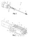
- FIG. 1is a perspective view of one embodiment of an endplate treatment instrument.
- FIG. 2is a perspective view of the distal portion of the instrument of FIG. 1 in an undeployed position.
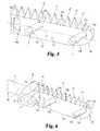
- FIGS. 3 and 4are perspective views of the distal portion of the instrument of FIG. 1 in a deployed position.
- FIG. 5is a perspective view showing a treatment member comprising a portion of the instrument of FIG. 1 .
- FIG. 6is a perspective view showing the treatment member of FIG. 5 coupled to a distal portion of an actuating member of the treatment instrument of FIG. 1 .
- FIG. 7is a perspective view showing the treatment member of FIG. 5 mounted to a distal portion of a mounting member of the instrument of FIG. 1 .
- FIG. 8is a perspective view showing the distal portion of the mounting member of FIG. 7 with the treatment member of FIG. 5 mounted thereto and oriented in a direction opposite that of the treatment member of FIG. 7 .
- FIG. 9is a perspective view of the mounting member comprising a portion of the treatment instrument of FIG. 1 .
- FIG. 10is a perspective view of the distal end portion of the mounting member of FIG. 9 .
- FIG. 11is a perspective view of a portion of the distal portion of an actuating member of the treatment instrument of FIG. 1 .
- FIG. 12is a perspective view of a pair of linkage plates engageable to the portion of the actuating member shown in FIG. 11 .
- FIG. 13is a perspective view showing the assembly of the actuating member, mounting member and treatment members of the treatment instrument of FIG. 1 with the handle assembly removed.
- FIG. 14is a perspective view of a boss assembly at a proximal end of the portion of the treatment instrument shown in FIG. 13 .
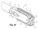
- FIG. 15is a perspective view of another embodiment distal end portion for the treatment instrument of FIG. 1 with the treatment members in a deployed position.
- FIG. 16is a perspective view of the handle assembly of the treatment instrument of FIG. 1 .
- FIG. 17is a perspective view showing the locking members of the handle assembly prior to insertion of the proximal boss members of the actuator assembly.
- FIG. 18is a perspective view showing the locking members of the handle assembly after insertion of the proximal boss members of the actuator assembly.
- FIG. 19is a perspective view showing the locking members of the handle assembly engaged with the proximal boss members of the actuator assembly.
- FIG. 20is a perspective view showing the handle assembly with the locking members engaged with the proximal boss members of the actuator assembly.
- FIG. 21is an exploded perspective view showing handle assembly of FIG. 16 .
- FIG. 22is a perspective view of another embodiment endplate treatment instrument.
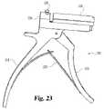
- FIG. 23is a perspective view of a proximal handle assembly provided with the treatment instrument of FIG. 22 .
- Treatment instrument 10includes a distal treatment system 12 , a proximal handle assembly 16 , and an actuating assembly 14 extending therebetween.
- Treatment system 12is positionable in a spinal disc space between adjacent endplates of a pair of opposing vertebrae.
- Treatment treatment system 12includes an undeployed position, as shown in FIGS. 1 and 2 , for insertion through a passageway through skin and tissue to the desired operative location.
- Treatment instrument 10can be manipulated to move treatment system 12 to a deployed position, as shown in FIGS. 3 and 4 , where the treatment members project outwardly to treat the adjacent vertebral endplates.
- treatment instrument 10can be manipulated to return treatment system 12 to its undeployed position for repositioning in the disc space for further treatments or for withdrawal from the patient through the passageway.
- Treatment system 12includes a plurality of first treatment members 26 and a plurality of second treatment member 28 .
- Treatment members 26each include a plurality of treatment portions 27 extending from one side thereof.
- Treatment member 28includes a plurality of treatment portions 29 extending from one side thereof in a direction opposite treatment portions 27 .
- treatment members 26include treatment portions 27 oriented in the same direction and are separated from one another by a treatment member 28 that includes treatment portions 29 oriented in the direction opposite the orientation of treatment portions 27 .
- Other embodimentscontemplate that two or more of the treatment members 26 and/or treatment members 28 are positioned directly adjacent one another. Still other embodiments contemplate a treatment instrument 10 with treatment portions that extend in only one direction when the treatment members are deployed.
- treatment portions 27 , 29provide a serrated surface along the respective treatment member 26 , 28 .
- the treatment portions 27 , 29include a plurality of pyramidally shaped spikes having a sharpened outer end to penetrate bone material of the vertebral endplate when deployed.
- Other shapes and formsare also contemplated for treatment portions 27 , 29 .
- treatment portions 27 , 29could include a plurality or series of elongated blades or sharp edges that extend transversely to a longitudinal axis 11 of treatment instrument 10 .
- treatment portions 27 , 29include one or more sharp edges that extend along the longitudinal axis 11 of treatment instrument 10 .
- Still other embodimentscontemplate treatment portions 27 , 29 in the form of spikes, barbs, or teeth with sharp ends. It is also contemplated that treatment portions 27 , 29 can include blunt ends that crush the adjacent bony structure when deployed.
- treatment members 26 , 28are substantially enclosed within a mounting portion 13 at the distal end of treatment instrument 10 .
- mounting portion 13prevents treatment portions 27 , 29 from contacting tissue or other anatomical structures as treatment system 12 is advanced to the desired location at the operative site.
- treatment portions 27 , 29are moved transversely to longitudinal axis 11 and extend outwardly from mounting portion 13 to engage the adjacent bony structure to provide treatment thereto.
- Treatment portions 27 , 29can at least partially penetrate, crush, or otherwise form openings in the bony material of the vertebral endplates when deployed. This promotes bleeding of the vertebral endplates and facilitates bone growth and implant incorporation in interbody fusion procedures. Treatment portions 27 , 29 can be withdrawn and redeployed as needed to provide the desired penetration and/or bleeding of the endplates. It is further contemplated that treatment instrument 10 can be manipulated with treatment portions 27 , 29 deployed to provide further endplate treatment. For example, treatment instrument 10 can be moved in the proximal-distal directions, laterally, and/or rotated in the disc space in small strokes with treatment portions 27 , 29 deployed. When the desired treatment has been obtained, treatment portions 27 , 29 can be withdrawn into mounting portion 13 , allowing withdrawal of treatment system 12 from the disc space and the patient's body without exposing tissue, nerves and other anatomical structures to treatment portions 27 , 29 .
- Treatment member 26includes an elongated body portion 100 extending between a proximal end 102 and a distal end 104 along longitudinal axis 101 .
- Treatment portions 27are spaced along longitudinal axis 101 and extend from a first side 105 of body portion 100 .
- Body portion 100includes a second side 103 extending along longitudinal axis 101 opposite treatment portions 27 .
- Second side 103includes a smooth surface profile along longitudinal axis 101 .
- second side 103can includes a curved profile adjacent distal end 104 so that distal end 104 has a blunt nose and reduced height relative to proximal end 102 .
- First side 105extends substantially parallel to longitudinal axis 101 , offsetting the blunt nose at distal end 104 from longitudinal axis 101 toward first side 105 .
- Body portion 100includes a proximal slot 106 orthogonally oriented to longitudinal axis 101 .
- Body portion 100further includes a proximal passage 108 and a distal passage 110 .
- Passages 108 , 110are inclined relative to longitudinal axis 101 so that passage 108 includes a distal end 109 and a proximal end 111 , and passage 110 includes a distal end 112 and a proximal end 113 .
- Distal ends 109 , 112are offset from longitudinal axis 101 and positioned adjacent treatment portions 27
- proximal ends 111 , 113are offset from longitudinal axis 101 and positioned adjacent second side 103 .
- Treatment member 28similarly includes a body portion 100 including a proximal slot 106 , a proximal passage 108 , and a distal passage 110 , as shown in FIG. 8 .
- Mounting portion 13is provided at the distal end of a mounting member 15 of actuator assembly 14 , as shown in FIGS. 9 and 10 .
- Mounting member 15includes a shaft 50 extending between a proximal end boss 52 and mounting portion 13 .
- Mounting portion 13includes a first flange member 20 spaced from a second flange member 22 .
- Flange members 20 , 22extend distally from an end member 24 at the distal end of shaft 50 .
- Flange members 20 , 22extend along and are offset laterally from longitudinal axis 11 , providing upper and lower openings and a distal end opening therebetween.
- Flange member 20includes a side opening 34 extending from a distal end wall 51 of end member 24 distally along a portion of the length of flange member 20 .
- flange member 22includes a side opening 36 extending from distal end wall 51 of end member 24 along a portion of the length of flange member 22 .
- a distal guide pin 30extends between and is secured in holes 31 , 35 adjacent the distal end noses 40 , 44 of flange members 20 , 22 .
- a proximal guide pin 32extends between and is secured in holes 33 , 37 located about mid-length along flange members 20 , 22 and distally of side openings 34 , 36 .
- Flange member 20includes distal end nose 40 having a blunt rounded shape
- flange member 22includes distal end nose 44 having a blunt rounded shape. The blunt rounded shape facilitates insertion through tissue and into the space between adjacent vertebrae.
- an actuating member 60is movably received in mounting member 15 .
- Actuating member 60includes a shaft 66 and a coupling assembly 70 at a distal end of shaft 66 .
- Shaft 66is positionable in a passage 57 ( FIG. 9 ) extending through shaft 50 of mounting member 15 that opens at distal end wall 51 of end member 24 .
- Coupling assembly 70includes a drive member 71 extending transversely from shaft 66 .
- a first linkage plate 72extends from distally from one side of drive member 71
- a second linkage plate 74extends distally from the opposite side of drive member 71 .
- a pin 78can be positioned through proximal hole 80 ( FIG.
- first linkage plate 72to couple linkage plate 72 to drive member 71 .
- a similar pincan pass through proximal hole 88 ( FIG. 12 ) of linkage plate 74 to couple linkage plate 74 to the other side of drive member 71 .
- a linkage member 76extends between linkage plates 72 , 74 , and is spaced distally from drive member 71 . Linkage member 76 can be secured in distal holes 84 , 86 of linkage plates 72 , 74 .
- treatment members 26 , 28When assembled, treatment members 26 , 28 are coupled to coupling assembly 70 and positioned between and movable relative to flange members 20 , 22 by movement of actuating member 60 .
- Treatment members 26 , 28are movably mounted to flange members 20 , 22 with distal guide pin 30 extending through distal passages 110 , and proximal guide pin 32 extending through proximal passages 108 .
- Linkage member 76 of coupling assembly 70extends through proximal slots 106 , and linkage plates 72 , 74 are received in respective ones of the side openings 34 , 36 .
- Drive member 71 of coupling assembly 70is positioned distally of distal end wall 51 of end member 24 between flange members 20 , 22 .
- Drive member 71is larger than the opening of passage 57 at the distal end of shaft 50 , and can contact distal end wall 51 to limit proximal movement of coupling assembly 70 and thus actuating member 60 relative to mounting member 15
- proximal member 71is adjacent end wall 51
- guide pin 32is located adjacent distal ends 112 of distal passages 110 and distal ends 109 of proximal passages 108 .
- Linkage member 76is located adjacent the upper end of proximal slots 106 .
- treatment members 26 , 28are retracted so that treatment portions 27 are recessed at or below the upper ends 41 , 45 of flange members 20 , 22 , and treatment portions 29 are recessed at or below the lower ends 43 , 46 of flange members 20 , 22 , as shown in FIG. 2 .
- the reduced height distal ends 104 of treatment members 26 , 28are substantially aligned with the rounded distal end noses of 40 , 44 of flange members 20 , 22 , as shown in FIG. 2 .
- Thisprovides treatment system 12 with a tapered leading end having smooth surface profile, facilitating insertion into a spinal disc space. It is contemplated that flange members 20 , 22 can facilitate recapitulation of a collapsed disc space as it is inserted therein.
- actuating member 60When deployed, actuating member 60 is moved distally relative to mounting member 15 , thereby advancing coupling assembly 70 distally between flange members 20 , 22 .
- This distal movementadvances treatment members 26 , 28 along guide pins 30 , 32 until guide pin 32 is located adjacent proximal ends 113 of distal passages 110 and proximal ends 111 of proximal passages 108 .
- the inclination of passages 108 , 110 relative to longitudinal axis 101 of treatment members 26 , 28causes treatment members 26 , 28 to move upwardly and downwardly, respectively, advancing treatment portions 27 , 29 beyond the upper ends 41 , 45 and lower ends 43 , 46 of flange members 20 , 22 .
- Linkage plates 72 , 74are simultaneously advanced distally in side openings 34 , 36 .
- treatment members 26are moved upwardly through the upper opening between flange members 20 , 22 when moving to the deployed position, and treatment members 28 are moved downwardly through the lower opening between flange members 20 , 22 when moving to the deployed position.
- Treatment members 26 , 28also move distally relative to flange members 20 , 22 so that distal ends 104 extend distally past distal ends 40 , 44 of flange members 20 , 22 through the distal opening between flange members 20 , 22 . It is contemplated that treatment members 26 , 28 move parallel to longitudinal axis 11 of treatment instrument 10 so that the entire length of treatment members 26 , 28 contacts the adjacent vertebral endplate to provide treatment thereto when deployed.
- the mounting arrangement between mounting portion 13 and treatment members 26 , 28facilitates the application of sufficient force to treatment members 26 , 28 so that treatment portions 27 , 29 can penetrate and/or crush the adjacent bony structure when deployed.
- Guide pins 30 , 32provide multiple support locations in the passages 110 , 108 of treatment members 26 , 28 to maintain parallel movement of the treatment members 26 , 28 relative to longitudinal axis 11 throughout the range of motion between deployed and undeployed positions.
- Distal movement of actuating member 60 in mounting member 15can be limited by any one or combination of contact of the guide pins 30 , 32 with the proximal ends of passages 110 , 108 ; contact of linkage member 76 with the end of slot 106 opposite the respective treatment portions 27 , 29 ; contact of linkage plates 72 , 74 with the distal ends of side opening 34 , 36 ; with an arrangement between the proximal ends of mounting member 15 and actuating member 60 ; or with the handle assembly 16 .
- Actuating assembly 14includes mounting member 15 and actuating member 60 movably received in passage 57 ( FIG. 9 ) extending through shaft 50 of mounting member 15 .
- Mounting member 15includes a boss 52 at a proximal end of shaft 50
- actuating member 60includes a boss 62 at a proximal end of shaft 66 .
- Boss 52includes a proximal extension 54 extending partially around passage 57
- boss 62includes a distal extension 64 extending partially around shaft 66 .
- Distal extension 64is movable along proximal extension 54 .
- Proximal movement of shaft 66 relative to shaft 50can be limited by, for example, contact of proximal member 71 with distal end wall 51 , to maintain extensions 54 , 64 in an overlapping arrangement.
- Distal movement of shaft 66 relative to shaft 50can be limited by, for example, contact of boss 62 with boss 52 .
- Proximal boss 62can include a first notch 68 formed in a first side thereof and a second opposing notch (not shown) in the opposite side.
- Proximal boss 52can include a first notch 58 formed in a first side thereof and a second opposing notch (not shown) in the opposite side. As discussed further below, notches 58 , 68 facilitate attachment of handle assembly 16 to bosses 52 , 62 .
- another embodiment treatment system 120includes treatment members 26 with treatment portions 27 projecting upwardly from flange members 20 , 22 and treatment members 28 with treatment portions 29 projecting downwardly from flange members 20 , 22 .
- four treatment members 26 , 28are provided and alternate with one another so that every other one of the treatment members extends upwardly or downwardly.
- the width between flange members 20 , 22can be reduced facilitating the use of treatment instrument 10 in minimally invasive surgical techniques.
- Other embodimentscontemplate other numbers of treatment members, including one treatment member up to ten or more treatment members.
- the treatment portions of adjacent treatment memberscan extend in opposite directions as shown. It is further contemplated that two or more adjacent treatment members can include treatment portions extending in the same direction.
- the vertebral endplate treatment instruments discussed hereincan be used in minimally invasive surgical techniques where the disc space is accessed through a micro-incision, a sleeve, or one or more retractors that provide a protected passageway to the disc space.
- the treatment instrumentsalso have application in open surgical techniques where skin and tissue are incised and retracted to expose the surgical site.
- the treatment instrumentscan be useful in posterior approaches to a spinal disc space where tissue, nerves, and the posterior vertebral elements hinder access to the disc space. Applications in other approaches, including anterior, anterior-oblique, lateral, and postero-lateral approaches are also contemplate.
- the treatment instrumentsalso have application in procedures that access any region of the spine, including the cervical, thoracic, lumbar and sacral regions.
- Handle assembly 16is shown removed from the distal portion of treatment instrument 10 shown in FIG. 13 .
- Handle assembly 16includes a proximal knob 140 and a body 144 extending from knob 140 .
- Handle assembly 16further includes a fixed shaft 146 coupled to body 144 , and a movable shaft 148 coupled to knob 140 .
- Actuating member 60is coupled to movable shaft 148 with locking member 150
- mounting member 15is coupled to fixed shaft 146 with locking member 152 .
- Locking members 150 , 152releasably engage notches 68 , 58 , respectively, to secure the distal portion of instrument 10 to handle assembly 16 .
- locking members 150 , 152without the remaining portions of handle assembly 16 .
- locking members 150 , 152are in their unlocked position so that cylindrical passage portions 154 , 158 are aligned with bosses 62 , 52 .
- Bosses 62 , 52are positionable through passage portions 154 , 158 to align notches 68 with non-cylindrical passage portion 156 of locking member 150 and to align notches 58 with non-cylindrical passage portion 160 of locking member 152 , as shown in FIG. 18 .
- Locking member 150can then be moved so that passage portion 156 engages notches 68 , and passage portion 160 engages notches 58 , as shown in FIGS. 19 and 20 .
- boss 62is engaged with movable shaft 148
- boss 52is engaged with fixed shaft 146 .
- Locking member 150includes a slotted receptacle 162 that receives a pin (not shown) coupled to movable shaft 148 to movably secure locking member 150 thereto.
- locking member 152includes a slotted receptacle 164 to receive a pin 166 coupled to fixed shaft 146 to movably secure locking member 150 thereto.
- one end of each of the locking members 150 , 152aligns with an outer surface of the corresponding shaft 146 , 148 while the other end protrudes outwardly therefrom.
- the other ends of locking members 150 , 152can be depressed to align passage portions 154 , 158 with bosses 62 , 52 to uncouple handle assembly 16 and allow its removal therefrom.
- knob 140is rotatable relative to body 144 in a first direction such as, for example, counterclockwise, to axially and distally advance movable shaft 148 within fixed shaft 146 .
- movable shaft 148can be provided with a threaded proximal end 168 that is threadingly engaged with knob 140 in body 144 .
- the non-rotating, distal movement of movable shaft 148distally advances actuating member 60 in mounting member 15 , thus deploying treatment members 26 , 28 from mounting portion 13 .
- Rotation of knob 140 in the opposite directionmoves movable shaft 148 and actuating member 60 proximally in the opposite direction to undeploy treatment members 26 , 28 while maintaining mounting member 15 stationary.
- Fixed shaft 146is engaged with body 144 with proximal extensions 170 that extend along threaded proximal end 168 .
- a torque handle 142can be provided that extends laterally from fixed shaft 146 .
- Torque handle 142can be grasped by the surgeon to facilitate insertion and withdrawal of the distal end of instrument 10 from the operative site.
- Torque handle 142can also assist in moving instrument 10 proximally, distally, and/or rotationally about axis 11 with treatment members 26 , 28 in the deployed condition to provide further treatment of the endplates.
- FIGS. 22-23show another embodiment treatment instrument 210 which can be identical to treatment instrument 10 above except for handle assembly 216 .
- Handle assembly 216employs a handle and lever arrangement to move actuating member 60 relative to mounting member 15 .
- Handle assembly 216includes a fixed handle 218 and a movable handle 220 .
- Movable handle 220can be coupled to a linkage 228 proximal of housing 224 .
- Linkage 228is coupled to the proximal end of actuating member 60 by, for example, a locking member 226 releasably engaged with notch 68 in proximal boss 62 in the manner discussed above with respect to handle assembly 16 .
- Fixed handle 218is fixedly coupled to housing 224 , which is fixedly coupled to the proximal end of mounting member 15 .
- a leaf spring 222can be provided between handles 218 , 220 to bias movable handle 220 away from fixed handle 218 , and thus normally positioning treatment members 26 , 28 to the undeployed position for insertion and withdrawal from the operative site.
- Handle 220is moved toward handle 218 to distally advance actuating member 60 relative to mounting member 15 and thereby deploy treatment member 26 , 28 from mounting portion 13 .
Landscapes
- Health & Medical Sciences (AREA)
- Surgery (AREA)
- Life Sciences & Earth Sciences (AREA)
- Biomedical Technology (AREA)
- Medical Informatics (AREA)
- Orthopedic Medicine & Surgery (AREA)
- Oral & Maxillofacial Surgery (AREA)
- Engineering & Computer Science (AREA)
- Dentistry (AREA)
- Heart & Thoracic Surgery (AREA)
- Nuclear Medicine, Radiotherapy & Molecular Imaging (AREA)
- Molecular Biology (AREA)
- Animal Behavior & Ethology (AREA)
- General Health & Medical Sciences (AREA)
- Public Health (AREA)
- Veterinary Medicine (AREA)
- Prostheses (AREA)
Abstract
Description
Claims (42)
Priority Applications (7)
| Application Number | Priority Date | Filing Date | Title |
|---|---|---|---|
| US10/422,221US7674265B2 (en) | 2003-04-24 | 2003-04-24 | Minimally invasive instruments and methods for preparing vertebral endplates |
| PCT/US2004/011565WO2004096055A2 (en) | 2003-04-24 | 2004-04-15 | Minimally invasive instruments for preparing vertebral endplates |
| EP04750151AEP1622516A2 (en) | 2003-04-24 | 2004-04-15 | Minimally invasive instruments for preparing vertebral endplates |
| AU2004233809AAU2004233809A1 (en) | 2003-04-24 | 2004-04-15 | Minimally invasive instruments for preparing vertebral endplates |
| CA002523257ACA2523257A1 (en) | 2003-04-24 | 2004-04-15 | Minimally invasive instruments and methods for preparing vertebral endplates |
| JP2006510052AJP2006524109A (en) | 2003-04-24 | 2004-04-15 | Minimally invasive instrument for preparing spinal endplates |
| US12/658,922US8460296B2 (en) | 2003-04-24 | 2010-02-17 | Minimally invasive instruments and methods for preparing vertebral endplates |
Applications Claiming Priority (1)
| Application Number | Priority Date | Filing Date | Title |
|---|---|---|---|
| US10/422,221US7674265B2 (en) | 2003-04-24 | 2003-04-24 | Minimally invasive instruments and methods for preparing vertebral endplates |
Related Child Applications (1)
| Application Number | Title | Priority Date | Filing Date |
|---|---|---|---|
| US12/658,922ContinuationUS8460296B2 (en) | 2003-04-24 | 2010-02-17 | Minimally invasive instruments and methods for preparing vertebral endplates |
Publications (2)
| Publication Number | Publication Date |
|---|---|
| US20040215197A1 US20040215197A1 (en) | 2004-10-28 |
| US7674265B2true US7674265B2 (en) | 2010-03-09 |
Family
ID=33298840
Family Applications (2)
| Application Number | Title | Priority Date | Filing Date |
|---|---|---|---|
| US10/422,221Active2027-12-21US7674265B2 (en) | 2003-04-24 | 2003-04-24 | Minimally invasive instruments and methods for preparing vertebral endplates |
| US12/658,922Expired - Fee RelatedUS8460296B2 (en) | 2003-04-24 | 2010-02-17 | Minimally invasive instruments and methods for preparing vertebral endplates |
Family Applications After (1)
| Application Number | Title | Priority Date | Filing Date |
|---|---|---|---|
| US12/658,922Expired - Fee RelatedUS8460296B2 (en) | 2003-04-24 | 2010-02-17 | Minimally invasive instruments and methods for preparing vertebral endplates |
Country Status (6)
| Country | Link |
|---|---|
| US (2) | US7674265B2 (en) |
| EP (1) | EP1622516A2 (en) |
| JP (1) | JP2006524109A (en) |
| AU (1) | AU2004233809A1 (en) |
| CA (1) | CA2523257A1 (en) |
| WO (1) | WO2004096055A2 (en) |
Cited By (50)
| Publication number | Priority date | Publication date | Assignee | Title |
|---|---|---|---|---|
| US20070142765A1 (en)* | 2003-05-21 | 2007-06-21 | Crosstrees Medical, Inc. | Extractable filler for inserting medicine into animal tissue |
| US20100152791A1 (en)* | 2003-04-24 | 2010-06-17 | Smith Maurice M | Minimally invasive instruments and methods for preparing vertebral endplates |
| US20110093024A1 (en)* | 2007-09-14 | 2011-04-21 | Layne Richard W | Method and apparatus for bone removal |
| US20110172670A1 (en)* | 2007-05-02 | 2011-07-14 | Depuy Products, Inc. | Expandable proximal reamer |
| US20130018377A1 (en)* | 2011-07-14 | 2013-01-17 | Alphatec Spine, Inc. | Instrument for removal of material from within a body |
| US8551098B2 (en) | 2010-08-17 | 2013-10-08 | Warsaw Orthopedic, Inc. | Bone scoring device |
| US8845733B2 (en) | 2010-06-24 | 2014-09-30 | DePuy Synthes Products, LLC | Lateral spondylolisthesis reduction cage |
| US8956357B2 (en) | 2007-05-02 | 2015-02-17 | DePuy Synthes Products, LLC | Expandable proximal reamer |
| US9226764B2 (en) | 2012-03-06 | 2016-01-05 | DePuy Synthes Products, Inc. | Conformable soft tissue removal instruments |
| US9247943B1 (en)* | 2009-02-06 | 2016-02-02 | Kleiner Intellectual Property, Llc | Devices and methods for preparing an intervertebral workspace |
| US9326806B2 (en) | 2003-09-02 | 2016-05-03 | Crosstrees Medical, Inc. | Devices and methods for the treatment of bone fracture |
| US9427264B2 (en) | 2008-12-05 | 2016-08-30 | Jeffrey KLEINER | Apparatus and method of spinal implant and fusion |
| US9439782B2 (en) | 2008-02-06 | 2016-09-13 | Jeffrey B. Kleiner | Spinal fusion cage system with inserter |
| US9629729B2 (en) | 2009-09-18 | 2017-04-25 | Spinal Surgical Strategies, Llc | Biological delivery system with adaptable fusion cage interface |
| US9655740B1 (en) | 2016-04-28 | 2017-05-23 | Spine Wave, Inc. | Expandable sizer instrument for spacing vertebral bodies |
| USD797290S1 (en) | 2015-10-19 | 2017-09-12 | Spinal Surgical Strategies, Llc | Bone graft delivery tool |
| US9931224B2 (en) | 2009-11-05 | 2018-04-03 | DePuy Synthes Products, Inc. | Self-pivoting spinal implant and associated instrumentation |
| US10022245B2 (en) | 2012-12-17 | 2018-07-17 | DePuy Synthes Products, Inc. | Polyaxial articulating instrument |
| US10195053B2 (en) | 2009-09-18 | 2019-02-05 | Spinal Surgical Strategies, Llc | Bone graft delivery system and method for using same |
| US10245159B1 (en) | 2009-09-18 | 2019-04-02 | Spinal Surgical Strategies, Llc | Bone graft delivery system and method for using same |
| USD853560S1 (en)* | 2008-10-09 | 2019-07-09 | Nuvasive, Inc. | Spinal implant insertion device |
| US20200100904A1 (en)* | 2013-08-09 | 2020-04-02 | Nuvasive Specialized Orthopedics, Inc. | Lordotic Expandable Interbody Implant |
| US10966843B2 (en) | 2017-07-18 | 2021-04-06 | DePuy Synthes Products, Inc. | Implant inserters and related methods |
| US10973656B2 (en) | 2009-09-18 | 2021-04-13 | Spinal Surgical Strategies, Inc. | Bone graft delivery system and method for using same |
| US11045331B2 (en) | 2017-08-14 | 2021-06-29 | DePuy Synthes Products, Inc. | Intervertebral implant inserters and related methods |
| US11344424B2 (en) | 2017-06-14 | 2022-05-31 | Medos International Sarl | Expandable intervertebral implant and related methods |
| US11369490B2 (en) | 2011-03-22 | 2022-06-28 | DePuy Synthes Products, Inc. | Universal trial for lateral cages |
| US11426290B2 (en) | 2015-03-06 | 2022-08-30 | DePuy Synthes Products, Inc. | Expandable intervertebral implant, system, kit and method |
| US11432942B2 (en) | 2006-12-07 | 2022-09-06 | DePuy Synthes Products, Inc. | Intervertebral implant |
| US11446155B2 (en) | 2017-05-08 | 2022-09-20 | Medos International Sarl | Expandable cage |
| US11446156B2 (en) | 2018-10-25 | 2022-09-20 | Medos International Sarl | Expandable intervertebral implant, inserter instrument, and related methods |
| US11452607B2 (en) | 2010-10-11 | 2022-09-27 | DePuy Synthes Products, Inc. | Expandable interspinous process spacer implant |
| US11497619B2 (en) | 2013-03-07 | 2022-11-15 | DePuy Synthes Products, Inc. | Intervertebral implant |
| US11510788B2 (en) | 2016-06-28 | 2022-11-29 | Eit Emerging Implant Technologies Gmbh | Expandable, angularly adjustable intervertebral cages |
| US11596523B2 (en) | 2016-06-28 | 2023-03-07 | Eit Emerging Implant Technologies Gmbh | Expandable and angularly adjustable articulating intervertebral cages |
| US11602438B2 (en) | 2008-04-05 | 2023-03-14 | DePuy Synthes Products, Inc. | Expandable intervertebral implant |
| US11607321B2 (en) | 2009-12-10 | 2023-03-21 | DePuy Synthes Products, Inc. | Bellows-like expandable interbody fusion cage |
| US11612491B2 (en) | 2009-03-30 | 2023-03-28 | DePuy Synthes Products, Inc. | Zero profile spinal fusion cage |
| US11622868B2 (en) | 2007-06-26 | 2023-04-11 | DePuy Synthes Products, Inc. | Highly lordosed fusion cage |
| US11654033B2 (en) | 2010-06-29 | 2023-05-23 | DePuy Synthes Products, Inc. | Distractible intervertebral implant |
| US11666455B2 (en) | 2009-09-18 | 2023-06-06 | Spinal Surgical Strategies, Inc., A Nevada Corporation | Bone graft delivery devices, systems and kits |
| US11737881B2 (en) | 2008-01-17 | 2023-08-29 | DePuy Synthes Products, Inc. | Expandable intervertebral implant and associated method of manufacturing the same |
| US11752009B2 (en) | 2021-04-06 | 2023-09-12 | Medos International Sarl | Expandable intervertebral fusion cage |
| US11806245B2 (en) | 2020-03-06 | 2023-11-07 | Eit Emerging Implant Technologies Gmbh | Expandable intervertebral implant |
| US11850160B2 (en) | 2021-03-26 | 2023-12-26 | Medos International Sarl | Expandable lordotic intervertebral fusion cage |
| US11872139B2 (en) | 2010-06-24 | 2024-01-16 | DePuy Synthes Products, Inc. | Enhanced cage insertion assembly |
| USRE49973E1 (en) | 2013-02-28 | 2024-05-21 | DePuy Synthes Products, Inc. | Expandable intervertebral implant, system, kit and method |
| US12090064B2 (en) | 2022-03-01 | 2024-09-17 | Medos International Sarl | Stabilization members for expandable intervertebral implants, and related systems and methods |
| US12279972B2 (en) | 2008-05-22 | 2025-04-22 | Spinal Surgical Strategies, Inc. | Spinal fusion cage system with inserter |
| US12440346B2 (en) | 2023-03-31 | 2025-10-14 | DePuy Synthes Products, Inc. | Expandable intervertebral implant |
Families Citing this family (24)
| Publication number | Priority date | Publication date | Assignee | Title |
|---|---|---|---|---|
| US8142462B2 (en) | 2004-05-28 | 2012-03-27 | Cavitech, Llc | Instruments and methods for reducing and stabilizing bone fractures |
| US7429264B2 (en)* | 2004-06-15 | 2008-09-30 | Warsaw Orthopedic, Inc. | Minimally invasive deployable cutting instrument |
| US7632275B2 (en)* | 2004-07-01 | 2009-12-15 | Howmedica Osteonics Corp. | Orthopedic reamer |
| WO2006081421A2 (en)* | 2005-01-27 | 2006-08-03 | Nexgen Spine, Inc. | Intervertebral disc replacement and surgical instruments therefor |
| EP1948041A2 (en)* | 2005-10-24 | 2008-07-30 | Nexgen Spine, Inc. | Intervertebral disc replacement and associated instrumentation |
| WO2008039850A2 (en)* | 2006-09-26 | 2008-04-03 | Nexgen Spine, Inc. | Intervertebral. prosthesis endplate having double dome and surgical tools for preparing the vertebral body endplate to receive the prosthesis |
| US20080269754A1 (en)* | 2007-03-06 | 2008-10-30 | Orthobond, Inc. | Preparation Tools and Methods of Using the Same |
| US8608745B2 (en)* | 2007-03-26 | 2013-12-17 | DePuy Synthes Products, LLC | System, apparatus, and method for cutting bone during an orthopaedic surgical procedure |
| US20090131952A1 (en) | 2007-05-21 | 2009-05-21 | Brian Schumacher | Delivery system and method for inflatable devices |
| CN101938945B (en)* | 2007-06-07 | 2013-12-04 | 史密夫和内修有限公司 | Device for preparing a knee joint for implants in knee surgery |
| US8221425B2 (en)* | 2008-04-30 | 2012-07-17 | Warsaw Orthopedic, Inc. | Percutaneous discectomy and endplate preparation tool |
| US8262663B2 (en)* | 2008-05-05 | 2012-09-11 | Ranier Limited | Endplate preparation instrument |
| US8470045B2 (en) | 2008-05-05 | 2013-06-25 | K2M, Inc. | Endplate for an intervertebral prosthesis and prosthesis incorporating the same |
| WO2010094032A2 (en) | 2009-02-16 | 2010-08-19 | Aoi Medical Inc. | Trauma nail accumulator |
| US8876828B2 (en)* | 2009-04-23 | 2014-11-04 | Ranier Limited | Vertebral surface preparation instrument |
| US9220554B2 (en)* | 2010-02-18 | 2015-12-29 | Globus Medical, Inc. | Methods and apparatus for treating vertebral fractures |
| US8257379B2 (en)* | 2010-07-29 | 2012-09-04 | Kyphon Sarl | Tissue structure perforation system and method |
| US12369923B2 (en)* | 2019-07-01 | 2025-07-29 | Fusion Orthopedics, Llc | Surgical instruments including a set of cutting burrs for performing an osteotomy |
| US9301849B2 (en)* | 2013-03-14 | 2016-04-05 | Warsaw Orthopedic, Inc. | Endplate punch template and method of use |
| CA2920576A1 (en)* | 2013-08-05 | 2015-02-12 | Scott L. Blumenthal | Vertebral endplate apparatus and method |
| US9545283B2 (en) | 2013-12-23 | 2017-01-17 | Jmea Corporation | Devices and methods for preparation of vertebral members |
| EP3195833B1 (en) | 2016-01-19 | 2022-01-12 | K2M, Inc. | Surgical instrument |
| US10531816B2 (en)* | 2016-02-01 | 2020-01-14 | Zimmer Biomet Spine, Inc. | Expandable paddle distractor |
| JP7625242B2 (en) | 2020-09-23 | 2025-02-03 | 国立大学法人東海国立大学機構 | Endplate perforator |
Citations (23)
| Publication number | Priority date | Publication date | Assignee | Title |
|---|---|---|---|---|
| US654164A (en)* | 1899-10-12 | 1900-07-24 | Henry J Lawrence | Expansion-drill. |
| US3702611A (en) | 1971-06-23 | 1972-11-14 | Meyer Fishbein | Surgical expansive reamer for hip socket |
| US3750652A (en)* | 1971-03-05 | 1973-08-07 | J Sherwin | Knee retractor |
| US5015255A (en) | 1989-05-10 | 1991-05-14 | Spine-Tech, Inc. | Spinal stabilization method |
| US5235966A (en)* | 1991-10-17 | 1993-08-17 | Jay Jamner | Endoscopic retractor |
| US5445639A (en) | 1989-05-10 | 1995-08-29 | Spine-Tech, Inc. | Intervertebral reamer construction |
| US5540693A (en)* | 1992-02-12 | 1996-07-30 | Sierra Surgical, Inc. | Surgical instrument for cutting hard tissue and method of use |
| US5591170A (en) | 1994-10-14 | 1997-01-07 | Genesis Orthopedics | Intramedullary bone cutting saw |
| US5601556A (en)* | 1994-03-18 | 1997-02-11 | Pisharodi; Madhavan | Apparatus for spondylolisthesis reduction |
| US5697889A (en)* | 1994-03-16 | 1997-12-16 | Gus J. Slotman | Surgical instruments useful for endoscopic spinal procedures |
| US5776054A (en)* | 1996-08-07 | 1998-07-07 | Bobra; Dilip | Apparatus for retracting tissue |
| US5928239A (en) | 1998-03-16 | 1999-07-27 | University Of Washington | Percutaneous surgical cavitation device and method |
| US6083228A (en)* | 1998-06-09 | 2000-07-04 | Michelson; Gary K. | Device and method for preparing a space between adjacent vertebrae to receive an insert |
| US6159214A (en)* | 1996-07-31 | 2000-12-12 | Michelson; Gary K. | Milling instrumentation and method for preparing a space between adjacent vertebral bodies |
| US6224604B1 (en) | 1999-07-30 | 2001-05-01 | Loubert Suddaby | Expandable orthopedic drill for vertebral interbody fusion techniques |
| WO2001060268A1 (en) | 2000-02-15 | 2001-08-23 | Spineology Group, Llc | Expandable reamer |
| US6454807B1 (en)* | 2000-11-30 | 2002-09-24 | Roger P. Jackson | Articulated expandable spinal fusion cage system |
| WO2002102256A1 (en) | 2001-06-18 | 2002-12-27 | Sdgi Holdings, Inc. | Surgical instrumentation and method for forming a passage in bone having an enlarged cross-sectional portion |
| US20030009169A1 (en)* | 2001-06-29 | 2003-01-09 | Young John Stewart | Fluoroscopic locator and registration device |
| US20030135218A1 (en) | 2002-01-17 | 2003-07-17 | Concept Martix, Llc | Diskectomy instrument and method |
| US20030225416A1 (en)* | 2002-05-21 | 2003-12-04 | Bonvallet Todd C. | Instruments and techniques for separating bony structures |
| WO2004080316A1 (en) | 2003-03-13 | 2004-09-23 | Sdgi Holdings, Inc. | Vertebral endplate preparation tool kit |
| US6840944B2 (en)* | 2002-05-21 | 2005-01-11 | Loubert Suddaby | Vertebral body end plate cutter |
Family Cites Families (3)
| Publication number | Priority date | Publication date | Assignee | Title |
|---|---|---|---|---|
| US5658335A (en)* | 1995-03-09 | 1997-08-19 | Cohort Medical Products Group, Inc. | Spinal fixator |
| DE19807236C2 (en)* | 1998-02-20 | 2000-06-21 | Biedermann Motech Gmbh | Intervertebral implant |
| US7674265B2 (en)* | 2003-04-24 | 2010-03-09 | Warsaw Orthopedic, Inc. | Minimally invasive instruments and methods for preparing vertebral endplates |
- 2003
- 2003-04-24USUS10/422,221patent/US7674265B2/enactiveActive
- 2004
- 2004-04-15AUAU2004233809Apatent/AU2004233809A1/ennot_activeAbandoned
- 2004-04-15CACA002523257Apatent/CA2523257A1/ennot_activeAbandoned
- 2004-04-15EPEP04750151Apatent/EP1622516A2/ennot_activeWithdrawn
- 2004-04-15JPJP2006510052Apatent/JP2006524109A/enactivePending
- 2004-04-15WOPCT/US2004/011565patent/WO2004096055A2/enactiveApplication Filing
- 2010
- 2010-02-17USUS12/658,922patent/US8460296B2/ennot_activeExpired - Fee Related
Patent Citations (26)
| Publication number | Priority date | Publication date | Assignee | Title |
|---|---|---|---|---|
| US654164A (en)* | 1899-10-12 | 1900-07-24 | Henry J Lawrence | Expansion-drill. |
| US3750652A (en)* | 1971-03-05 | 1973-08-07 | J Sherwin | Knee retractor |
| US3702611A (en) | 1971-06-23 | 1972-11-14 | Meyer Fishbein | Surgical expansive reamer for hip socket |
| US5445639A (en) | 1989-05-10 | 1995-08-29 | Spine-Tech, Inc. | Intervertebral reamer construction |
| US5062845A (en) | 1989-05-10 | 1991-11-05 | Spine-Tech, Inc. | Method of making an intervertebral reamer |
| US5015255A (en) | 1989-05-10 | 1991-05-14 | Spine-Tech, Inc. | Spinal stabilization method |
| US5235966A (en)* | 1991-10-17 | 1993-08-17 | Jay Jamner | Endoscopic retractor |
| US5540693A (en)* | 1992-02-12 | 1996-07-30 | Sierra Surgical, Inc. | Surgical instrument for cutting hard tissue and method of use |
| US5697889A (en)* | 1994-03-16 | 1997-12-16 | Gus J. Slotman | Surgical instruments useful for endoscopic spinal procedures |
| US5601556A (en)* | 1994-03-18 | 1997-02-11 | Pisharodi; Madhavan | Apparatus for spondylolisthesis reduction |
| US5591170A (en) | 1994-10-14 | 1997-01-07 | Genesis Orthopedics | Intramedullary bone cutting saw |
| US6159214A (en)* | 1996-07-31 | 2000-12-12 | Michelson; Gary K. | Milling instrumentation and method for preparing a space between adjacent vertebral bodies |
| US5776054A (en)* | 1996-08-07 | 1998-07-07 | Bobra; Dilip | Apparatus for retracting tissue |
| US5928239A (en) | 1998-03-16 | 1999-07-27 | University Of Washington | Percutaneous surgical cavitation device and method |
| US6083228A (en)* | 1998-06-09 | 2000-07-04 | Michelson; Gary K. | Device and method for preparing a space between adjacent vertebrae to receive an insert |
| US6224604B1 (en) | 1999-07-30 | 2001-05-01 | Loubert Suddaby | Expandable orthopedic drill for vertebral interbody fusion techniques |
| WO2001060268A1 (en) | 2000-02-15 | 2001-08-23 | Spineology Group, Llc | Expandable reamer |
| US6383188B2 (en) | 2000-02-15 | 2002-05-07 | The Spineology Group Llc | Expandable reamer |
| US6454807B1 (en)* | 2000-11-30 | 2002-09-24 | Roger P. Jackson | Articulated expandable spinal fusion cage system |
| WO2002102256A1 (en) | 2001-06-18 | 2002-12-27 | Sdgi Holdings, Inc. | Surgical instrumentation and method for forming a passage in bone having an enlarged cross-sectional portion |
| US20030009169A1 (en)* | 2001-06-29 | 2003-01-09 | Young John Stewart | Fluoroscopic locator and registration device |
| US20030135218A1 (en) | 2002-01-17 | 2003-07-17 | Concept Martix, Llc | Diskectomy instrument and method |
| US6726690B2 (en)* | 2002-01-17 | 2004-04-27 | Concept Matrix, Llc | Diskectomy instrument and method |
| US20030225416A1 (en)* | 2002-05-21 | 2003-12-04 | Bonvallet Todd C. | Instruments and techniques for separating bony structures |
| US6840944B2 (en)* | 2002-05-21 | 2005-01-11 | Loubert Suddaby | Vertebral body end plate cutter |
| WO2004080316A1 (en) | 2003-03-13 | 2004-09-23 | Sdgi Holdings, Inc. | Vertebral endplate preparation tool kit |
Cited By (99)
| Publication number | Priority date | Publication date | Assignee | Title |
|---|---|---|---|---|
| US8460296B2 (en)* | 2003-04-24 | 2013-06-11 | Warsaw Orthopedic, Inc. | Minimally invasive instruments and methods for preparing vertebral endplates |
| US20100152791A1 (en)* | 2003-04-24 | 2010-06-17 | Smith Maurice M | Minimally invasive instruments and methods for preparing vertebral endplates |
| US20070142765A1 (en)* | 2003-05-21 | 2007-06-21 | Crosstrees Medical, Inc. | Extractable filler for inserting medicine into animal tissue |
| US9113988B2 (en) | 2003-05-21 | 2015-08-25 | Crosstrees Medical, Inc. | Method for inserting medicine into animal tissue |
| US9326806B2 (en) | 2003-09-02 | 2016-05-03 | Crosstrees Medical, Inc. | Devices and methods for the treatment of bone fracture |
| US11712345B2 (en) | 2006-12-07 | 2023-08-01 | DePuy Synthes Products, Inc. | Intervertebral implant |
| US11642229B2 (en) | 2006-12-07 | 2023-05-09 | DePuy Synthes Products, Inc. | Intervertebral implant |
| US11432942B2 (en) | 2006-12-07 | 2022-09-06 | DePuy Synthes Products, Inc. | Intervertebral implant |
| US11497618B2 (en) | 2006-12-07 | 2022-11-15 | DePuy Synthes Products, Inc. | Intervertebral implant |
| US11660206B2 (en) | 2006-12-07 | 2023-05-30 | DePuy Synthes Products, Inc. | Intervertebral implant |
| US8956357B2 (en) | 2007-05-02 | 2015-02-17 | DePuy Synthes Products, LLC | Expandable proximal reamer |
| US20110172670A1 (en)* | 2007-05-02 | 2011-07-14 | Depuy Products, Inc. | Expandable proximal reamer |
| US8632546B2 (en) | 2007-05-02 | 2014-01-21 | DePuy Synthes Products, LLC | Expandable proximal reamer |
| US11622868B2 (en) | 2007-06-26 | 2023-04-11 | DePuy Synthes Products, Inc. | Highly lordosed fusion cage |
| US20110093024A1 (en)* | 2007-09-14 | 2011-04-21 | Layne Richard W | Method and apparatus for bone removal |
| US9066732B2 (en)* | 2007-09-14 | 2015-06-30 | Crosstrees Medical, Inc. | Method and apparatus for bone removal |
| US11737881B2 (en) | 2008-01-17 | 2023-08-29 | DePuy Synthes Products, Inc. | Expandable intervertebral implant and associated method of manufacturing the same |
| US11129730B2 (en) | 2008-02-06 | 2021-09-28 | Spinal Surgical Strategies, Inc., a Nevada corpora | Spinal fusion cage system with inserter |
| US10179054B2 (en) | 2008-02-06 | 2019-01-15 | Jeffrey B. Kleiner | Spinal fusion cage system with inserter |
| US9439782B2 (en) | 2008-02-06 | 2016-09-13 | Jeffrey B. Kleiner | Spinal fusion cage system with inserter |
| US11712341B2 (en) | 2008-04-05 | 2023-08-01 | DePuy Synthes Products, Inc. | Expandable intervertebral implant |
| US11602438B2 (en) | 2008-04-05 | 2023-03-14 | DePuy Synthes Products, Inc. | Expandable intervertebral implant |
| US11617655B2 (en) | 2008-04-05 | 2023-04-04 | DePuy Synthes Products, Inc. | Expandable intervertebral implant |
| US11701234B2 (en) | 2008-04-05 | 2023-07-18 | DePuy Synthes Products, Inc. | Expandable intervertebral implant |
| US12011361B2 (en) | 2008-04-05 | 2024-06-18 | DePuy Synthes Products, Inc. | Expandable intervertebral implant |
| US11712342B2 (en) | 2008-04-05 | 2023-08-01 | DePuy Synthes Products, Inc. | Expandable intervertebral implant |
| US12023255B2 (en) | 2008-04-05 | 2024-07-02 | DePuy Synthes Products, Inc. | Expandable inter vertebral implant |
| US11707359B2 (en) | 2008-04-05 | 2023-07-25 | DePuy Synthes Products, Inc. | Expandable intervertebral implant |
| US12279972B2 (en) | 2008-05-22 | 2025-04-22 | Spinal Surgical Strategies, Inc. | Spinal fusion cage system with inserter |
| USD853560S1 (en)* | 2008-10-09 | 2019-07-09 | Nuvasive, Inc. | Spinal implant insertion device |
| US9861496B2 (en) | 2008-12-05 | 2018-01-09 | Jeffrey B. Kleiner | Apparatus and method of spinal implant and fusion |
| US9427264B2 (en) | 2008-12-05 | 2016-08-30 | Jeffrey KLEINER | Apparatus and method of spinal implant and fusion |
| US9826988B2 (en) | 2009-02-06 | 2017-11-28 | Kleiner Intellectual Property, Llc | Devices and methods for preparing an intervertebral workspace |
| US9247943B1 (en)* | 2009-02-06 | 2016-02-02 | Kleiner Intellectual Property, Llc | Devices and methods for preparing an intervertebral workspace |
| US10201355B2 (en) | 2009-02-06 | 2019-02-12 | Kleiner Intellectual Property, Llc | Angled surgical tool for removing tissue from within an intervertebral space |
| US11612491B2 (en) | 2009-03-30 | 2023-03-28 | DePuy Synthes Products, Inc. | Zero profile spinal fusion cage |
| US12097124B2 (en) | 2009-03-30 | 2024-09-24 | DePuy Synthes Products, Inc. | Zero profile spinal fusion cage |
| US10245159B1 (en) | 2009-09-18 | 2019-04-02 | Spinal Surgical Strategies, Llc | Bone graft delivery system and method for using same |
| US11666455B2 (en) | 2009-09-18 | 2023-06-06 | Spinal Surgical Strategies, Inc., A Nevada Corporation | Bone graft delivery devices, systems and kits |
| US11660208B2 (en) | 2009-09-18 | 2023-05-30 | Spinal Surgical Strategies, Inc. | Bone graft delivery system and method for using same |
| US12053393B2 (en) | 2009-09-18 | 2024-08-06 | Spinal Surgical Strategies, Inc. | Bone graft delivery system and method for use |
| US9629729B2 (en) | 2009-09-18 | 2017-04-25 | Spinal Surgical Strategies, Llc | Biological delivery system with adaptable fusion cage interface |
| US10973656B2 (en) | 2009-09-18 | 2021-04-13 | Spinal Surgical Strategies, Inc. | Bone graft delivery system and method for using same |
| US10195053B2 (en) | 2009-09-18 | 2019-02-05 | Spinal Surgical Strategies, Llc | Bone graft delivery system and method for using same |
| US12167971B2 (en) | 2009-09-18 | 2024-12-17 | Spinal Surgical Strategies, Inc. | Bone graft delivery devices, systems and kits |
| US10792166B2 (en) | 2009-11-05 | 2020-10-06 | DePuy Synthes Products, Inc. | Self-pivoting spinal implant and associated instrumentation |
| US10195049B2 (en) | 2009-11-05 | 2019-02-05 | DePuy Synthes Products, Inc. | Self-pivoting spinal implant and associated instrumentation |
| US9931224B2 (en) | 2009-11-05 | 2018-04-03 | DePuy Synthes Products, Inc. | Self-pivoting spinal implant and associated instrumentation |
| US11712349B2 (en) | 2009-11-05 | 2023-08-01 | DePuy Synthes Products, Inc. | Self-pivoting spinal implant and associated instrumentation |
| US11607321B2 (en) | 2009-12-10 | 2023-03-21 | DePuy Synthes Products, Inc. | Bellows-like expandable interbody fusion cage |
| US9801639B2 (en) | 2010-06-24 | 2017-10-31 | DePuy Synthes Products, Inc. | Lateral spondylolisthesis reduction cage |
| US10449057B2 (en) | 2010-06-24 | 2019-10-22 | DePuy Synthes Products, Inc. | Lateral spondylolisthesis reduction cage |
| US12318304B2 (en) | 2010-06-24 | 2025-06-03 | DePuy Synthes Products, Inc. | Lateral spondylolisthesis reduction cage |
| US9801640B2 (en) | 2010-06-24 | 2017-10-31 | DePuy Synthes Products, Inc. | Lateral spondylolisthesis reduction cage |
| US10405989B2 (en) | 2010-06-24 | 2019-09-10 | DePuy Synthes Products, Inc. | Lateral spondylolisthesis reduction cage |
| US9907560B2 (en) | 2010-06-24 | 2018-03-06 | DePuy Synthes Products, Inc. | Flexible vertebral body shavers |
| US8845733B2 (en) | 2010-06-24 | 2014-09-30 | DePuy Synthes Products, LLC | Lateral spondylolisthesis reduction cage |
| US9763678B2 (en) | 2010-06-24 | 2017-09-19 | DePuy Synthes Products, Inc. | Multi-segment lateral cage adapted to flex substantially in the coronal plane |
| US9282979B2 (en) | 2010-06-24 | 2016-03-15 | DePuy Synthes Products, Inc. | Instruments and methods for non-parallel disc space preparation |
| US10588754B2 (en) | 2010-06-24 | 2020-03-17 | DePuy Snythes Products, Inc. | Lateral spondylolisthesis reduction cage and instruments and methods for non-parallel disc space preparation |
| US11911287B2 (en) | 2010-06-24 | 2024-02-27 | DePuy Synthes Products, Inc. | Lateral spondylolisthesis reduction cage |
| US11872139B2 (en) | 2010-06-24 | 2024-01-16 | DePuy Synthes Products, Inc. | Enhanced cage insertion assembly |
| US9592063B2 (en) | 2010-06-24 | 2017-03-14 | DePuy Synthes Products, Inc. | Universal trial for lateral cages |
| US10646350B2 (en) | 2010-06-24 | 2020-05-12 | DePuy Synthes Products, Inc. | Multi-segment lateral cages adapted to flex substantially in the coronal plane |
| US11654033B2 (en) | 2010-06-29 | 2023-05-23 | DePuy Synthes Products, Inc. | Distractible intervertebral implant |
| US8551098B2 (en) | 2010-08-17 | 2013-10-08 | Warsaw Orthopedic, Inc. | Bone scoring device |
| US11452607B2 (en) | 2010-10-11 | 2022-09-27 | DePuy Synthes Products, Inc. | Expandable interspinous process spacer implant |
| US11369490B2 (en) | 2011-03-22 | 2022-06-28 | DePuy Synthes Products, Inc. | Universal trial for lateral cages |
| US9204896B2 (en)* | 2011-07-14 | 2015-12-08 | Alphatec Spine, Inc. | Instrument for removal of material from within a body |
| US20130018377A1 (en)* | 2011-07-14 | 2013-01-17 | Alphatec Spine, Inc. | Instrument for removal of material from within a body |
| US9226764B2 (en) | 2012-03-06 | 2016-01-05 | DePuy Synthes Products, Inc. | Conformable soft tissue removal instruments |
| US10022245B2 (en) | 2012-12-17 | 2018-07-17 | DePuy Synthes Products, Inc. | Polyaxial articulating instrument |
| USRE49973E1 (en) | 2013-02-28 | 2024-05-21 | DePuy Synthes Products, Inc. | Expandable intervertebral implant, system, kit and method |
| US11850164B2 (en) | 2013-03-07 | 2023-12-26 | DePuy Synthes Products, Inc. | Intervertebral implant |
| US11497619B2 (en) | 2013-03-07 | 2022-11-15 | DePuy Synthes Products, Inc. | Intervertebral implant |
| US11696836B2 (en)* | 2013-08-09 | 2023-07-11 | Nuvasive, Inc. | Lordotic expandable interbody implant |
| US20200100904A1 (en)* | 2013-08-09 | 2020-04-02 | Nuvasive Specialized Orthopedics, Inc. | Lordotic Expandable Interbody Implant |
| US12213893B2 (en) | 2013-08-09 | 2025-02-04 | Nuvasive, Inc. | Lordotic expandable interbody implant and method of using same |
| US11426290B2 (en) | 2015-03-06 | 2022-08-30 | DePuy Synthes Products, Inc. | Expandable intervertebral implant, system, kit and method |
| USD797290S1 (en) | 2015-10-19 | 2017-09-12 | Spinal Surgical Strategies, Llc | Bone graft delivery tool |
| US9655740B1 (en) | 2016-04-28 | 2017-05-23 | Spine Wave, Inc. | Expandable sizer instrument for spacing vertebral bodies |
| US11596522B2 (en) | 2016-06-28 | 2023-03-07 | Eit Emerging Implant Technologies Gmbh | Expandable and angularly adjustable intervertebral cages with articulating joint |
| US12433757B2 (en) | 2016-06-28 | 2025-10-07 | Eit Emerging Implant Technologies Gmbh | Expandable, angularly adjustable and articulating intervertebral cages |
| US12390343B2 (en) | 2016-06-28 | 2025-08-19 | Eit Emerging Implant Technologies Gmbh | Expandable, angularly adjustable intervertebral cages |
| US11596523B2 (en) | 2016-06-28 | 2023-03-07 | Eit Emerging Implant Technologies Gmbh | Expandable and angularly adjustable articulating intervertebral cages |
| US11510788B2 (en) | 2016-06-28 | 2022-11-29 | Eit Emerging Implant Technologies Gmbh | Expandable, angularly adjustable intervertebral cages |
| US12427031B2 (en) | 2017-05-08 | 2025-09-30 | Medos International Sarl | Expandable cage |
| US11446155B2 (en) | 2017-05-08 | 2022-09-20 | Medos International Sarl | Expandable cage |
| US11344424B2 (en) | 2017-06-14 | 2022-05-31 | Medos International Sarl | Expandable intervertebral implant and related methods |
| US10966843B2 (en) | 2017-07-18 | 2021-04-06 | DePuy Synthes Products, Inc. | Implant inserters and related methods |
| US11045331B2 (en) | 2017-08-14 | 2021-06-29 | DePuy Synthes Products, Inc. | Intervertebral implant inserters and related methods |
| US11690734B2 (en) | 2017-08-14 | 2023-07-04 | DePuy Synthes Products, Inc. | Intervertebral implant inserters and related methods |
| US11446156B2 (en) | 2018-10-25 | 2022-09-20 | Medos International Sarl | Expandable intervertebral implant, inserter instrument, and related methods |
| US11806245B2 (en) | 2020-03-06 | 2023-11-07 | Eit Emerging Implant Technologies Gmbh | Expandable intervertebral implant |
| US11850160B2 (en) | 2021-03-26 | 2023-12-26 | Medos International Sarl | Expandable lordotic intervertebral fusion cage |
| US11752009B2 (en) | 2021-04-06 | 2023-09-12 | Medos International Sarl | Expandable intervertebral fusion cage |
| US12023258B2 (en) | 2021-04-06 | 2024-07-02 | Medos International Sarl | Expandable intervertebral fusion cage |
| US12090064B2 (en) | 2022-03-01 | 2024-09-17 | Medos International Sarl | Stabilization members for expandable intervertebral implants, and related systems and methods |
| US12440346B2 (en) | 2023-03-31 | 2025-10-14 | DePuy Synthes Products, Inc. | Expandable intervertebral implant |
Also Published As
| Publication number | Publication date |
|---|---|
| US8460296B2 (en) | 2013-06-11 |
| WO2004096055A2 (en) | 2004-11-11 |
| AU2004233809A1 (en) | 2004-11-11 |
| EP1622516A2 (en) | 2006-02-08 |
| JP2006524109A (en) | 2006-10-26 |
| US20100152791A1 (en) | 2010-06-17 |
| WO2004096055A3 (en) | 2005-01-20 |
| CA2523257A1 (en) | 2004-11-11 |
| US20040215197A1 (en) | 2004-10-28 |
Similar Documents
| Publication | Publication Date | Title |
|---|---|---|
| US7674265B2 (en) | Minimally invasive instruments and methods for preparing vertebral endplates | |
| US7429264B2 (en) | Minimally invasive deployable cutting instrument | |
| US12150638B2 (en) | Method and apparatus for performing spine surgery | |
| US12396863B2 (en) | Methods and apparatus for performing spine surgery | |
| US12239551B2 (en) | Sagittal balance systems and methods of use thereof | |
| US12016782B2 (en) | Methods and apparatus of performing spine surgery | |
| US10111759B2 (en) | Method and apparatus for minimally invasive insertion of intervertebral implants | |
| US8613745B2 (en) | Methods, systems and devices for carpal tunnel release | |
| EP0681811A2 (en) | Surgical instruments useful for endoscopic spinal procedures | |
| US20110160772A1 (en) | Systems and methods for performing spinal fusion | |
| US20140257489A1 (en) | Method and apparatus for minimally invasive insertion of intervertebral implants | |
| JP7583029B2 (en) | Interspinous-Interlaminar Stabilization Systems and Methods - Patent application | |
| CA2661869A1 (en) | Tissue access guidewire system and method | |
| US9968370B2 (en) | Multi-tine cutting device | |
| KR20230136630A (en) | Systems and methods for treating sacroiliac joints | |
| WO2007075152A1 (en) | Minimally invasive instruments and methods for preparing vertebral endplates | |
| US20190336118A1 (en) | Instruments and surgical techniques for disc preparation | |
| WO2003043505A1 (en) | Methods and instrumentation for disc space distraction |
Legal Events
| Date | Code | Title | Description |
|---|---|---|---|
| AS | Assignment | Owner name:SDGI HOLDINGS, INC., DELAWARE Free format text:ASSIGNMENT OF ASSIGNORS INTEREST;ASSIGNORS:SMITH, MAURICE M.;LIM, ROY;ROEHM, III, THOMAS E.;REEL/FRAME:014004/0487;SIGNING DATES FROM 20030331 TO 20030404 Owner name:SDGI HOLDINGS, INC.,DELAWARE Free format text:ASSIGNMENT OF ASSIGNORS INTEREST;ASSIGNORS:SMITH, MAURICE M.;LIM, ROY;ROEHM, III, THOMAS E.;SIGNING DATES FROM 20030331 TO 20030404;REEL/FRAME:014004/0487 | |
| AS | Assignment | Owner name:WARSAW ORTHOPEDIC, INC.,INDIANA Free format text:MERGER;ASSIGNOR:SDGI HOLDINGS, INC.;REEL/FRAME:018573/0086 Effective date:20061201 Owner name:WARSAW ORTHOPEDIC, INC., INDIANA Free format text:MERGER;ASSIGNOR:SDGI HOLDINGS, INC.;REEL/FRAME:018573/0086 Effective date:20061201 | |
| STCF | Information on status: patent grant | Free format text:PATENTED CASE | |
| FPAY | Fee payment | Year of fee payment:4 | |
| AS | Assignment | Owner name:WARSAW ORTHOPEDIC, INC, INDIANA Free format text:CORRECTIVE ASSIGNMENT TO CORRECT T0 REMOVE APPLICATION NUMBER PREVIOUSLY RECORDED AT REEL: 018573 FRAME: 0086. ASSIGNOR(S) HEREBY CONFIRMS THE MERGER;ASSIGNOR:SDGI HOLDINGS, INC.;REEL/FRAME:033904/0891 Effective date:20061201 | |
| MAFP | Maintenance fee payment | Free format text:PAYMENT OF MAINTENANCE FEE, 8TH YEAR, LARGE ENTITY (ORIGINAL EVENT CODE: M1552) Year of fee payment:8 | |
| MAFP | Maintenance fee payment | Free format text:PAYMENT OF MAINTENANCE FEE, 12TH YEAR, LARGE ENTITY (ORIGINAL EVENT CODE: M1553); ENTITY STATUS OF PATENT OWNER: LARGE ENTITY Year of fee payment:12 |