US7674260B2 - Emergency hemostasis device utilizing energy - Google Patents
Emergency hemostasis device utilizing energyDownload PDFInfo
- Publication number
- US7674260B2 US7674260B2US11/118,653US11865305AUS7674260B2US 7674260 B2US7674260 B2US 7674260B2US 11865305 AUS11865305 AUS 11865305AUS 7674260 B2US7674260 B2US 7674260B2
- Authority
- US
- United States
- Prior art keywords
- electrode
- base member
- tissue
- electrode carrier
- radio frequency
- Prior art date
- Legal status (The legal status is an assumption and is not a legal conclusion. Google has not performed a legal analysis and makes no representation as to the accuracy of the status listed.)
- Active, expires
Links
- 230000023597hemostasisEffects0.000titleclaimsabstractdescription102
- 230000000740bleeding effectEffects0.000claimsabstractdescription30
- 230000006378damageEffects0.000claimsabstractdescription20
- 238000000034methodMethods0.000claimsabstractdescription11
- 238000002679ablationMethods0.000claimsdescription40
- 239000000969carrierSubstances0.000claimsdescription33
- 239000012811non-conductive materialSubstances0.000claimsdescription15
- 230000003213activating effectEffects0.000claimsdescription4
- 230000023555blood coagulationEffects0.000claimsdescription3
- 230000015271coagulationEffects0.000abstractdescription2
- 238000005345coagulationMethods0.000abstractdescription2
- 210000001519tissueAnatomy0.000description74
- 208000032843HemorrhageDiseases0.000description26
- 208000034158bleedingDiseases0.000description26
- 210000003811fingerAnatomy0.000description16
- 210000004185liverAnatomy0.000description15
- 239000000463materialSubstances0.000description13
- 208000027418Wounds and injuryDiseases0.000description6
- 208000014674injuryDiseases0.000description6
- 206010028980NeoplasmDiseases0.000description5
- 239000004677NylonSubstances0.000description4
- 239000012530fluidSubstances0.000description4
- 229920001778nylonPolymers0.000description4
- 239000008280bloodSubstances0.000description3
- 210000004369bloodAnatomy0.000description3
- 210000000056organAnatomy0.000description3
- 238000001356surgical procedureMethods0.000description3
- 229920002725thermoplastic elastomerPolymers0.000description3
- 230000008733traumaEffects0.000description3
- 230000001276controlling effectEffects0.000description2
- 238000007796conventional methodMethods0.000description2
- 230000000881depressing effectEffects0.000description2
- 239000004744fabricSubstances0.000description2
- 239000007788liquidSubstances0.000description2
- 210000003813thumbAnatomy0.000description2
- RYGMFSIKBFXOCR-UHFFFAOYSA-NCopperChemical compound[Cu]RYGMFSIKBFXOCR-UHFFFAOYSA-N0.000description1
- 229920002334SpandexPolymers0.000description1
- 229940030225antihemorrhagicsDrugs0.000description1
- 230000015572biosynthetic processEffects0.000description1
- 230000001112coagulating effectEffects0.000description1
- 239000011248coating agentSubstances0.000description1
- 238000000576coating methodMethods0.000description1
- 239000002131composite materialSubstances0.000description1
- 238000010276constructionMethods0.000description1
- 229910052802copperInorganic materials0.000description1
- 239000010949copperSubstances0.000description1
- 230000003247decreasing effectEffects0.000description1
- -1e.g.Substances0.000description1
- 230000000694effectsEffects0.000description1
- 238000005516engineering processMethods0.000description1
- PCHJSUWPFVWCPO-UHFFFAOYSA-NgoldChemical compound[Au]PCHJSUWPFVWCPO-UHFFFAOYSA-N0.000description1
- 239000010931goldSubstances0.000description1
- 229910052737goldInorganic materials0.000description1
- 210000004247handAnatomy0.000description1
- 239000002874hemostatic agentSubstances0.000description1
- 239000012212insulatorSubstances0.000description1
- 210000005228liver tissueAnatomy0.000description1
- 239000002184metalSubstances0.000description1
- 229910052751metalInorganic materials0.000description1
- 238000012986modificationMethods0.000description1
- 230000004048modificationEffects0.000description1
- 238000012544monitoring processMethods0.000description1
- 239000004033plasticSubstances0.000description1
- 230000001105regulatory effectEffects0.000description1
- 238000000926separation methodMethods0.000description1
- 239000004759spandexSubstances0.000description1
- 210000004291uterusAnatomy0.000description1
- 230000000007visual effectEffects0.000description1
Images


Classifications
- A—HUMAN NECESSITIES
- A61—MEDICAL OR VETERINARY SCIENCE; HYGIENE
- A61B—DIAGNOSIS; SURGERY; IDENTIFICATION
- A61B18/00—Surgical instruments, devices or methods for transferring non-mechanical forms of energy to or from the body
- A61B18/04—Surgical instruments, devices or methods for transferring non-mechanical forms of energy to or from the body by heating
- A61B18/12—Surgical instruments, devices or methods for transferring non-mechanical forms of energy to or from the body by heating by passing a current through the tissue to be heated, e.g. high-frequency current
- A61B18/14—Probes or electrodes therefor
- A—HUMAN NECESSITIES
- A41—WEARING APPAREL
- A41D—OUTERWEAR; PROTECTIVE GARMENTS; ACCESSORIES
- A41D19/00—Gloves
- A41D19/0024—Gloves with accessories
- A—HUMAN NECESSITIES
- A61—MEDICAL OR VETERINARY SCIENCE; HYGIENE
- A61B—DIAGNOSIS; SURGERY; IDENTIFICATION
- A61B42/00—Surgical gloves; Finger-stalls specially adapted for surgery; Devices for handling or treatment thereof
- A61B42/10—Surgical gloves
- A—HUMAN NECESSITIES
- A61—MEDICAL OR VETERINARY SCIENCE; HYGIENE
- A61B—DIAGNOSIS; SURGERY; IDENTIFICATION
- A61B18/00—Surgical instruments, devices or methods for transferring non-mechanical forms of energy to or from the body
- A61B2018/00571—Surgical instruments, devices or methods for transferring non-mechanical forms of energy to or from the body for achieving a particular surgical effect
- A61B2018/00589—Coagulation
- A—HUMAN NECESSITIES
- A61—MEDICAL OR VETERINARY SCIENCE; HYGIENE
- A61B—DIAGNOSIS; SURGERY; IDENTIFICATION
- A61B2218/00—Details of surgical instruments, devices or methods for transferring non-mechanical forms of energy to or from the body
- A61B2218/001—Details of surgical instruments, devices or methods for transferring non-mechanical forms of energy to or from the body having means for irrigation and/or aspiration of substances to and/or from the surgical site
- A61B2218/007—Aspiration
- A—HUMAN NECESSITIES
- A61—MEDICAL OR VETERINARY SCIENCE; HYGIENE
- A61B—DIAGNOSIS; SURGERY; IDENTIFICATION
- A61B42/00—Surgical gloves; Finger-stalls specially adapted for surgery; Devices for handling or treatment thereof
Definitions
- This inventionrelates to a medical device and procedure.
- a trauma victim with a wound to certain organs in the bodycan be at significant risk of bleeding to death if the bleeding cannot be quickly controlled.
- the liveris formed from a parenchymatous (porous) tissue that can bleed profusely when injured.
- a conventional technique for controlling the bleedingis to apply immediate pressure to the tissue, however, as soon as the pressure is removed, the bleeding can resume.
- Gauze type products, such as QuikClot®are available, that include a hemostatic agent to promote blood clotting.
- removing the gauzecan reopen the wound, leading to additional bleeding.
- bleedingmust be stopped immediately and often cannot wait until a victim is transferred to a medical facility.
- the inventionfeatures an apparatus for substantially achieving hemostasis by tissue ablation.
- the apparatusincludes a base member, an electrode carrier, a vacuum line and a controller.
- the electrode carrieris attached to a surface of the base member and includes one or more bipolar electrodes that are configured to connect to a source of radio frequency energy.
- the vacuum lineis configured to connect to a vacuum source and to draw moisture away from the one or more bipolar electrodes during tissue ablation.
- the controlleris electrically coupled to the electrode carrier and configured to control the delivery of radio frequency energy to the one or more bipolar electrodes, such that tissue in contact with the electrode carrier can be ablated to a desired depth of destruction to achieve substantial hemostasis.
- the inventionfeatures a system for substantially achieving hemostasis by tissue ablation.
- the systemincludes a hemostasis device, a source of radio frequency, a controller and a vacuum source.
- the hemostasis deviceincludes a base member, an electrode carrier and a vacuum line.
- the electrode carrieris attached to a surface of the base member and includes one or more bipolar electrodes.
- the one or more bipolar electrodesare configured to connect to the source of radio frequency energy.
- the vacuum lineis configured to connect to the vacuum source.
- the source of radio frequency energyis electrically coupled to the one or more bipolar electrodes.
- the controlleris configured to control the delivery of radio frequency energy from the source of radio frequency energy to the one or more bipolar electrodes, such that tissue can be ablated to a desired depth of destruction to achieve substantial hemostasis.
- the vacuum sourceis coupled to the vacuum line and operable to draw bleeding tissue into contact with the electrode carrier and to draw moisture generated during delivery of radio frequency energy to the one or more bipolar electrodes and ablation of the tissue away from the one or more bipolar electrodes, and to substantially eliminate liquid surrounding the one or more bipolar electrodes.
- the apparatuscan further include a porous layer positioned between the base member and the electrode carrier, the porous layer coupled to the vacuum line.
- the base member and the electrode carrier attached theretocan be substantially flexible, alternatively, the base member can be substantially rigid.
- the base memberis a glove including a palm region and finger regions and the electrode carrier is attached to the palm region of the base member.
- the glovecan include one or more additional electrode carriers attached to the finger regions.
- the electrode carriercan include woven strips of a non-conductive material, where the one or more bipolar electrodes include electrode wires woven in a first direction between the strips of non-conductive material.
- sets of two or more electrode wiresare woven in a first direction between each strip of non-conductive material orientated in the first direction, where each set of electrode wires alternates polarity, and a pair of sets of electrode wires comprises a bipolar electrode.
- the base membercan be substantially cylindrically shaped, and the electrode carrier attached to an exterior surface of the cylindrically shaped base member.
- a second electrode carriercan be attached to an interior surface of the cylindrically shaped base member.
- the inventionfeatures a method for blood coagulation.
- An electrode carrier of a hemostasis deviceis positioned in contact with bleeding tissue.
- the hemostasis deviceincludes a base member, the electrode carrier attached to a surface of the base member, the electrode carrier including one or more bipolar electrodes connected to a source of radio frequency energy, and a vacuum line connected to a vacuum source.
- a vacuum sourceis activated to draw the bleeding tissue into closer contact with the electrode carrier and to draw moisture released from the tissue during ablation away from the one or more bipolar electrodes.
- the source of radio frequency energyis activated and radio frequency energy is delivered to the one or more bipolar electrodes and ablates the tissue in contact with the one or more bipolar electrodes.
- the delivery of the radio frequency energyis ceased upon reaching a desired depth of destruction of the tissue. Hemostasis is substantially achieved in a region of the ablation.
- the inventionfeatures an apparatus for achieving hemostasis by tissue ablation including a base member shaped as a glove configured to be worn by a user.
- the apparatusfurther includes an electrode carrier attached to a surface of the base member and a controller.
- the electrode carrierincludes one or more bipolar electrodes that are configured to connect to a source of radio frequency energy.
- the controlleris electrically coupled to the electrode carrier and configured to control the delivery of radio frequency energy to the one or more bipolar electrodes, such that tissue in contact with the electrode carrier can be ablated to a desired depth of destruction to achieve substantial hemostasis.
- Implementations of the apparatuscan include one or more of the following.
- a porous layercan be positioned between the base member and the electrode carrier, the porous layer including a vacuum line configured to connect to a vacuum source and to draw moisture away from the one or more bipolar electrodes during tissue ablation.
- the base membercan include a palm region and finger regions and the electrode carrier can be attached to the palm region of the base member.
- the apparatuscan include one or more additional electrode carriers attached to undersides of the finger regions of the base member.
- the base membercan include a main region corresponding to the hand of a glove and finger regions corresponding to fingers of a glove where the electrode carrier is attached to a top side of the main region opposite to a palm side of the main region.
- One or more additional electrode carrierscan be attached to top sides of the finger regions of the base member.
- the electrode carrier or carrierscan include woven strips of a non-conductive material, where the one or more bipolar electrodes include electrode wires woven in a first direction between the strips of non-conductive material.
- sets of two or more electrode wiresare woven in a first direction between each strip of non-conductive material orientated in the first direction, where each set of electrode wires alternates polarity, and a pair of sets of electrode wires is a bipolar electrode.
- Hemostasisthe stoppage of bleeding, can be achieved quickly and in difficult to access locations in a patient's body.
- the hemostasis devicecan be used in trauma situations, such as the battleground, accident scenes or an emergency room, to quickly control bleeding and prevent the patient from bleeding to death. Tissue types that can bleed profusely and are difficult treat can be treated using the hemostasis device.
- the liveris a good example, as bleeding from the liver can be difficult to control, even under operating room conditions.
- the hemostasis devicecan have different configurations that are suited to different applications, for example, the device can be flexible, rigid, shaped as a glove, shaped cylindrically, etc.
- the depth of destruction of the tissuecan be controlled so as to desiccate and coagulate the superficial tissue, without causing additional or unnecessary injury.
- the electrode carrier on the hemostasis devicecan be removed without restarting the bleeding, nor does pressure need to be applied after desiccation is complete.
- FIG. 1Ais a schematic representation of a hemostasis device.
- FIG. 1Bis a schematic representation of an alternative embodiment of the hemostasis device of FIG. 1A .
- FIG. 2is an enlarged view of a portion of an electrode carrier.
- FIG. 3is an enlarged cross-sectional view of a portion of an electrode carrier.
- FIG. 4is a schematic representation of a system including a hemostasis device.
- FIG. 5is a side view of a portion of a hemostasis device in contact with tissue.
- FIG. 6is a flowchart showing a process for coagulating blood using a hemostasis device.
- FIGS. 7A-Dare schematic representations of cross-sectional views showing electrodes in contact with tissue for ablation.
- FIG. 8is a schematic representation of an alternative embodiment of a hemostasis device.
- FIG. 9is a schematic representation of another alternative embodiment of a hemostasis device.
- FIG. 10is a schematic representation of a cylindrically shaped embodiment of a hemostasis device.
- a method and system for achieving hemostasis(the stoppage of bleeding) is described.
- RF (radio frequency) energyis used to ablate the surface of tissue to stop bleeding.
- the depth of destruction of the tissuecan be controlled so as to desiccate and coagulate the superficial tissue, without causing additional or unnecessary injury.
- An electrode carrier including bipolar electrodescan be applied to the tissue, and RF energy transmitted through the bipolar electrodes to ablate the tissue.
- a layer of desiccated tissuee.g., approximately 1 mm thick, can be created as well as coagulation of the tissue to achieve hemostasis.
- the electrode carriercan be removed without restarting the bleeding, nor does pressure need to be applied after desiccation is complete.
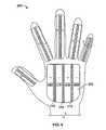
- the base member of the hemostasis device 100is configured as a glove and includes one or more electrode carriers.
- a first electrode carrier 102is included in the palm of the glove shaped hemostasis device 100
- five narrower electrode carriers 104 - 112are included on the fingers and thumb of the hemostasis device 100 .
- the glove-shaped hemostasis device 100can fit over a user's hand, and is flexible so that the fingers can be extended or curled, etc., as desired by the user.
- the electrode carrierscan have different configurations, e.g., the electrodes can extend along the proximal and/or distal ends of the palm and/or fingers.
- the electrode carriersare on the exterior surface of the glove shaped device, i.e., on the “top side” of the hand rather than on the “palm side”.
- a first electrode carrier 103is included on the top of the glove shaped hemostasis device 101
- five narrower electrode carriers 105 - 113are including on the tops of the fingers and thumb.
- a usercan position the hemostasis device 101 within a cavity, e.g., a uterus, and form a fist to achieve hemostasis of the tissue within the cavity.
- electrode carrierscan be included on both the palm side and top side of the glove shaped device, or can be included on the fingers only or the palm and top of the hand only. Other configurations are possible.
- the electrode carrier 102is formed from a woven insulative base material 114 , which in one embodiment can be thin, plastic strips. Woven between the strips of base material 114 are electrodes 116 . In this embodiment, the electrodes 116 are gold plated copper wires and two electrodes 116 are woven between each strip of base material 114 . The electrodes 116 can be oppositely charged between each strip of base material 114 .
- electrodes 116 acan be positively charged, and electrodes 116 b can be negatively charged, with the strip of base material 114 providing a non-conductive region between the bi-polar electrode regions 116 a , 116 b .
- a single electrode 116can be woven between each strip of base material 114 , with each electrode 116 alternating conductivity.
- more than two electrodes 116can be woven between each strip of base material.
- a pair of oppositely charged electrodes (or a pair of sets of electrodes)is referred to herein as a “bipolar electrode”.
- the electrodes 116are electrically coupled to a connector 118 that can be electrically coupled by a cable 120 to an RF generator.
- the body 122 of the glove shaped hemostasis device 100can be formed from a relatively thin and flexible material, e.g., nylon. As part of the body 122 , or as a separate layer, a thermally insulating layer is included to protect the user's hand from temperatures generated during use of the hemostasis device 100 (e.g., from steam created from tissue desiccation).
- the electrode carrier 102includes a porous layer 124 between the body 122 of the glove and the strips of base material 114 and electrodes 116 .
- a vacuum line 126is included within or under the porous layer 124 and is coupled to a vacuum port 128 that can be connected by a fluid line 130 to a vacuum source ( FIG. 1 ).
- the porous layer 124is configured such that when vacuum is applied through the vacuum line 126 , tissue can be drawn into contact with the electrode carrier 102 ; the porous layer 124 facilitates spreading the vacuum over the surface of the electrode carrier 102 .
- the porous layer 124can be formed from nylon and/or spandex.
- An electrode 116is shown woven between the strips of base material 114 .
- a systemincluding the hemostasis device 100 , an RF generator 140 and a vacuum source 142 .
- the RF generator 140is coupled to the hemostasis device 100 by the cable 120 .
- the vacuum source 142is coupled to the hemostasis device 100 by the fluid line 130 .
- the vacuum source 142can be activated by a foot pedal 144 , to allow an operator of the hemostasis device 100 to keep both hands free to work with the bleeding tissue.
- the RF generator 140 and the vacuum source 142are combined into a single RF controller unit, which includes the RF generator, vacuum source, a vacuum monitoring system as well as a foot pedal 144 for activating both the RF energy and the vacuum.
- a user input deviceincluding a display (e.g., similar to user input device 146 shown) can be included in the single RF controller unit.
- an operatorcan control which electrode carriers 102 - 112 are activated when using the hemostasis device 100 . That is, for a particular application, using the palm electrode carrier 102 alone may be desirable. In an alterative application, for example, where a finger electrode carrier 106 can be placed over a cut in damaged tissue, it may be desirable to only activate the finger electrode carrier 106 , so as not to unnecessarily ablate healthy (i.e., undamaged) tissue in contact with other parts of the hemostasis device 100 .
- the RF generator 140can be connected to a user input device 146 to receive instructions from a user as to which electrode carriers to activate.
- the user input device 146includes a touch screen display 148 .
- a visual representation of the hemostasis device 100is shown on the touch screen display 148 .
- Each electrode carrier on the hemostasis device 100is represented by a corresponding graphic representation on the touch screen display 148 .
- the electrode carrier graphicbecomes highlighted, indicating it has been selected, and by touching the graphic a second time, the electrode carrier is deselected.
- the RF generatorwhen activated (e.g., by depressing a foot pedal 144 ), is instructed to transmit RF energy to the palm electrode carrier 102 .
- routing the RF energy in this mannercan be accomplished by having separate electrical connections, or pins, from the RF generator to each electrode carrier. Selecting a certain electrode carrier on the touch screen display 148 instructs the RF generator to close the switch to the pin of the corresponding electrode carrier on the hemostasis device 100 . In this manner, once RF energy is initiated, the RF energy flows to only those electrode carriers that have been selected on the touch screen display 148 . The user can select to activate some or all of the six electrode carriers 102 - 112 . In one embodiment, conventional touch screen technology can be used to implement the touch screen display 148 . Other types of user input devices 146 can be used, and the touch screen display 148 is just one example.
- FIG. 5shows a side view of the hemostasis device 100 in contact with damaged tissue 150 .
- a process 200 for using the hemostasis device 100 to stop bleeding from the damaged tissue 150shall be described for illustrative purposes.
- the hemostasis device 100is first positioned by the user in contact with the damaged tissue 150 (step 202 ).
- the usercan exercise his/her discretion as to how the hemostasis device 100 is positioned, depending on the configuration of the tissue 150 to be treated.
- the electrode carriers to be activatedcan be selected by the user or an assistant selectively touching the corresponding areas on the touch screen display 148 (step 204 ).
- the vacuum source 142is activated, e.g., by depressing foot pedal 144 (step 206 ), causing the damaged tissue 150 to be drawn into closer contact with the hemostasis device 100 , and simultaneous evacuation of blood, vapors and/or other material.
- the RF generator 140receives the input from the user input device 146 and transmits RF energy to the selected electrode carrier 102 (step 206 ).
- the damaged tissue 150is ablated in the area in contact with the electrode carrier 102 until a desired depth of destruction is reached (step 208 ).
- the region 152 depicted in FIG. 5represents the desiccated tissue.
- the RF energy and vacuumare ceased (step 210 ) and the hemostasis device 100 can be removed from the tissue 150 (step 212 ).
- Ablating the upper surface of the bleeding tissuee.g., to a depth of approximately 1 to 7 mm, depending upon the type of tissue treated, desiccates and coagulates the tissue and achieves hemostasis. Because the bleeding has ceased due to desiccation of the tissue, rather than due to the application of pressure, the hemostasis device can be removed without restarting the bleeding.
- a non-stick coatingcan be applied to the surface of the hemostasis device 100 to promote separation from the tissue after hemostasis is achieved and the procedure is complete.
- a controller included in the RF generator 140can monitor the impedance of the tissue at the electrodes 116 and include an automatic shut-off once a threshold impedance is detected.
- tissue 150is desiccated by the RF energy, fluid is lost and withdrawn from the region by the vacuum 140 into the porous layer 124 and removed through the vacuum line 126 .
- the vacuumdraws moisture released by the tissue undergoing ablation away from the electrode carrier 102 and prevents formation of a low-impedance liquid layer around the electrodes 116 during ablation. As more of the tissue is desiccated, the higher the impedance experienced at the electrodes 116 .
- a threshold impedance levelcan be set that corresponds to a desired depth of ablation. Once the threshold impedance is detected, the controller shuts off the RF energy, controlling the depth of tissue destruction.
- the RF generator 140can be designed such that above the threshold impedance level the RF generator's ability to deliver RF energy is greatly reduced, which in effect automatically terminates energy delivery.
- the depth of destructionis a function of a number of factors, including the tissue impedance, center-to-center distance between the positive and negative electrodes of a bipolar electrode and the surface density of the electrodes, as described further below.
- the user input device 146can be configured to permit a user to select the depth of destruction, for example, by selecting the surface density of electrodes and/or center-to-center distance between the electrodes.
- more or fewer electrodes 116can be woven between each strip of base material 114 , thereby increasing the surface density of the electrodes 116 . If greater ablation depth is desired, more electrodes 116 , e.g., five, can be woven between each strip of base material 114 . Additionally, increasing the center-to-center distance between the positive electrode and negative electrode of a bipolar electrode can increase the depth of destruction. In the present example, a first set of five electrodes 116 can be positively energized and the adjacent set of five electrodes 116 negatively energized, which pattern is repeated across the electrode carrier 102 .
- the entire grouping of 10 electrodes, i.e., the 5 positive and 5 negative electrodes, togetherare one bipolar electrode.
- the center-to-center distance between the set of positive electrodes and set of negative electrodesis thereby increased, which can increase the depth of ablation.
- each electrodeis energized at a polarity opposite from that of its neighboring electrodes.
- energy field patternsdesignated 222 , 224 and 226 in FIG. 7A , are generated between the electrode sites and thus help to direct the flow of current through the tissue T to form a region of ablation A.
- electrode spacingis increased by energizing, for example, every third or fifth electrode 220 rather than all electrodes, the energy patterns will extend more deeply into the tissue. See, for example, pattern 224 which results from energization of electrodes having a non-energized electrode between them, or pattern 226 which results from energization of electrodes having two non-energized electrodes between them.
- the depth of ablationis also effected by the electrode density (i.e., the percentage of the target tissue area which is in contact with active electrode surfaces) and may be regulated by pre-selecting the amount of this active electrode coverage. For example, the depth of ablation is much greater when the active electrode surface covers more than 10% of the target tissue than it is when the active electrode surfaces covers only 1% of the target tissue.
- the electrodes 220 Awhich have more active area in contact with the underlying tissue T, produce a region of ablation A 1 that extends more deeply into the tissue T than the ablation region A 2 produced by the low density electrodes 220 B, even though the electrode spacings and widths are the same for the high and low density electrodes.
- electrode widthshaving spacings with less than 1% active electrode surface coverage, and their resultant ablation depth, based on an ablation area of 6 cm 2 and a power of 20-40 watts, are given on the following table:
- the depth of ablationis significantly less when the active electrode surface coverage is decreased.
- a usermay set the RF generator 140 to energize electrodes which will produce a desired electrode spacing and active electrode area.
- alternate electrodesmay be energized as shown in FIG. 7C , with the first three energized electrodes having positive polarity, the second three having negative polarity, etc. All six electrodes together can be referred to as one bipolar electrode.
- FIG. 7Dif greater ablation depth is desired the first five electrodes may be positively energized, and the seventh through eleventh electrodes negatively energized, with the sixth electrode remaining inactivated to provide adequate electrode spacing.
- a usercan therefore not only control which electrode carriers are activated, but in one implementation can also control which electrodes are energized within an electrode carrier to produce a desired depth of destruction.
- an electrode carriere.g., the palm electrode carrier 302
- the electrodes 316are conductive and alternate between positive and negative polarity.
- Non-conductive insulator regions 318separate the electrodes 316 .
- the fabriccan be a composite yarn with a thermoplastic elastomer (TPE) core and multiple polyfilament nylon bundles wound around the TPE as a cover.
- the nylon bundlesare plated with thin, conductive metal layers. This construction is flexible, and can facilitate achieving close contact between the electrode carrier 302 and an irregularly shaped area of tissue.
- Other configurations for the electrode carriers 102 - 112are possible, and the above described embodiments are merely exemplary electrode carriers.
- the hemostasis devicehas been described with reference to an embodiment where the electrode carrier or carriers are on the surface of a glove that can be worn by a user.
- the base member 400can be a paddle with a handle.
- One or more electrode carriers 402can be affixed to the surface of the paddle 400 , which can be manipulated by a user into a position in contact with damaged tissue.
- a porous layeris included beneath the electrode carrier 402 and a vacuum source can be connected to a vacuum line within or under the porous layer to provide vacuum at the electrode carrier surface, as described above in reference to the glove-shaped embodiment.
- the paddle 400can be formed smaller than a human hand, such that the paddle 400 can reach into areas that might otherwise be inaccessible by a human hand if using the glove-configured hemostasis device 100 .
- the paddle 400 and electrode carrier 402can be formed larger than the palm of a human hand, such that the electrode carrier 402 can be used to cover relatively large areas of damaged tissue, i.e., larger than can be covered by the palm electrode carrier 102 of the glove-configured hemostasis device 100 .
- Other configurations of the hemostasis deviceare possible, including different shapes and sizes.
- the paddle 400 , or otherwise configured base membercan be flexible so as to conform to the surface of damaged tissue, or can be substantially rigid, which may be desirable in certain applications.
- the hemostasis devicecan be used to achieve hemostasis under urgent, life-threatening conditions, e.g., on a battlefield or at the scene of an accident, or under controlled conditions, e.g., during surgery.
- a soldier suffering an injury to the liver on the battlefieldis often at risk of bleeding to death within a considerably short period of time.
- the liveris an organ that once damaged can bleed profusely, and the surface is such that the liver cannot simply be sutured to stop bleeding.
- the hemostasis devicefor example the glove-shaped hemostasis device 100 , can be ideal in such situations.
- a usercan put on the glove-shaped hemostasis device 100 , reach into the soldier's body, find the damaged liver, activate the desired one or more electrode carriers, and achieve hemostasis in a very short period of time.
- a soldier who may have otherwise bled to deathcould be saved using the hemostasis device 100 .
- the hemostasis devicecan also be useful in surgical procedures.
- a liverthat has been diagnosed as including a tumor that must be removed to save a patient's life.
- one or more incisions into the liverwould be necessary.
- Cutting into the liver tissuetypically triggers profuse bleeding that can be difficult to control, even under operating room conditions.
- the hemostasis devicecan instead be used to achieve almost immediate hemostasis, avoiding unnecessary blood loss from the patient.
- a user wearing the glove-shaped hemostasis device 100can lay a finger over the incision and activate the electrode carrier corresponding to the finger. RF energy transmitted to the activated electrode carrier can quickly achieve hemostasis.
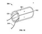
- the base member of the hemostasis device 500can be cylindrically shaped as shown in FIG. 10 .
- One or more bipolar electrodes 504can be positioned on the exterior surface of the hemostasis device 500 .
- a cable 508can connect the one or more bipolar electrodes 504 to an RF energy source, and a fluid line 506 can connect a porous layer beneath the bipolar electrodes to a vacuum source.
- a distal end 502 of the hemostasis device 500can be sharpened so the hemostasis device 500 can cut into the tissue while being inserted into position.
- the hemostasis device 500can be inserted into tissue, for example, a liver including a tumor, so that the tumor is within the interior of the hemostasis device 500 when it is positioned in the liver.
- the one or more bipolar electrodes 504 on the exterior of the hemostasis device 500can be activated, and the surrounding tissue ablated.
- the hemostasis device 500 and the tissue within the interior corecan be removed from the liver.
- the tumoris thereby extracted from the liver, and hemostasis in achieved in the surrounding tissue.
- one or more bipolar electrodescan be included on the interior of the hemostasis device 500 .
- Other configurationsare possible.
Landscapes
- Health & Medical Sciences (AREA)
- Surgery (AREA)
- Engineering & Computer Science (AREA)
- Life Sciences & Earth Sciences (AREA)
- Animal Behavior & Ethology (AREA)
- Molecular Biology (AREA)
- Veterinary Medicine (AREA)
- Public Health (AREA)
- Biomedical Technology (AREA)
- Heart & Thoracic Surgery (AREA)
- Medical Informatics (AREA)
- General Health & Medical Sciences (AREA)
- Physics & Mathematics (AREA)
- Otolaryngology (AREA)
- Plasma & Fusion (AREA)
- Nuclear Medicine, Radiotherapy & Molecular Imaging (AREA)
- Textile Engineering (AREA)
- Surgical Instruments (AREA)
Abstract
Description
| ELECTRODE WIDTH SPACING APPROX. DEPTH |
| 1 | mm | 1-2 | mm | 1-3 | mm |
| 1-2.5 | mm | 3-6 | mm | 5-7 | mm |
| 1-4.5 | mm | 8-10 | mm | 8-10 | mm |
| ELECTRODE WIDTH SPACING APPROX. DEPTH |
| 1 | mm | 1-2 | mm | 0.5-1 | mm |
| 1-2.5 | mm | 3-6 | mm | 2-3 | mm |
| 1-4.5 | mm | 8-10 | mm | 2-3 | mm |
Claims (25)
Priority Applications (5)
| Application Number | Priority Date | Filing Date | Title |
|---|---|---|---|
| US11/118,653US7674260B2 (en) | 2005-04-28 | 2005-04-28 | Emergency hemostasis device utilizing energy |
| PCT/US2006/014898WO2006115986A2 (en) | 2005-04-28 | 2006-04-19 | Hemostasis device |
| TW095115363ATWI325771B (en) | 2005-04-28 | 2006-04-28 | Hemostasis device |
| US12/719,714US8277445B2 (en) | 2005-04-28 | 2010-03-08 | Ablation device |
| US13/604,160US8523856B2 (en) | 2005-04-28 | 2012-09-05 | Hemostasis device |
Applications Claiming Priority (1)
| Application Number | Priority Date | Filing Date | Title |
|---|---|---|---|
| US11/118,653US7674260B2 (en) | 2005-04-28 | 2005-04-28 | Emergency hemostasis device utilizing energy |
Related Child Applications (1)
| Application Number | Title | Priority Date | Filing Date |
|---|---|---|---|
| US12/719,714ContinuationUS8277445B2 (en) | 2005-04-28 | 2010-03-08 | Ablation device |
Publications (2)
| Publication Number | Publication Date |
|---|---|
| US20060247614A1 US20060247614A1 (en) | 2006-11-02 |
| US7674260B2true US7674260B2 (en) | 2010-03-09 |
Family
ID=36956004
Family Applications (3)
| Application Number | Title | Priority Date | Filing Date |
|---|---|---|---|
| US11/118,653Active2026-11-28US7674260B2 (en) | 2005-04-28 | 2005-04-28 | Emergency hemostasis device utilizing energy |
| US12/719,714Expired - Fee RelatedUS8277445B2 (en) | 2005-04-28 | 2010-03-08 | Ablation device |
| US13/604,160Expired - Fee RelatedUS8523856B2 (en) | 2005-04-28 | 2012-09-05 | Hemostasis device |
Family Applications After (2)
| Application Number | Title | Priority Date | Filing Date |
|---|---|---|---|
| US12/719,714Expired - Fee RelatedUS8277445B2 (en) | 2005-04-28 | 2010-03-08 | Ablation device |
| US13/604,160Expired - Fee RelatedUS8523856B2 (en) | 2005-04-28 | 2012-09-05 | Hemostasis device |
Country Status (3)
| Country | Link |
|---|---|
| US (3) | US7674260B2 (en) |
| TW (1) | TWI325771B (en) |
| WO (1) | WO2006115986A2 (en) |
Cited By (3)
| Publication number | Priority date | Publication date | Assignee | Title |
|---|---|---|---|---|
| US20100160908A1 (en)* | 2005-04-28 | 2010-06-24 | Sampson Russel M | Hemostasis Device |
| US9204921B2 (en) | 2012-12-13 | 2015-12-08 | Cook Medical Technologies Llc | RF energy controller and method for electrosurgical medical devices |
| US9364277B2 (en) | 2012-12-13 | 2016-06-14 | Cook Medical Technologies Llc | RF energy controller and method for electrosurgical medical devices |
Families Citing this family (25)
| Publication number | Priority date | Publication date | Assignee | Title |
|---|---|---|---|---|
| US20040215235A1 (en) | 1999-11-16 | 2004-10-28 | Barrx, Inc. | Methods and systems for determining physiologic characteristics for treatment of the esophagus |
| US20060095032A1 (en) | 1999-11-16 | 2006-05-04 | Jerome Jackson | Methods and systems for determining physiologic characteristics for treatment of the esophagus |
| WO2001035846A1 (en) | 1999-11-16 | 2001-05-25 | Ganz Robert A | System and method of treating abnormal tissue in the human esophagus |
| US8048070B2 (en) | 2000-03-06 | 2011-11-01 | Salient Surgical Technologies, Inc. | Fluid-assisted medical devices, systems and methods |
| ES2306706T3 (en) | 2000-03-06 | 2008-11-16 | Salient Surgical Technologies, Inc. | FLUID SUPPLY SYSTEM AND CONTROLLER FOR ELECTROCHURGICAL DEVICES. |
| US6558385B1 (en) | 2000-09-22 | 2003-05-06 | Tissuelink Medical, Inc. | Fluid-assisted medical device |
| US6953461B2 (en) | 2002-05-16 | 2005-10-11 | Tissuelink Medical, Inc. | Fluid-assisted medical devices, systems and methods |
| US7811282B2 (en) | 2000-03-06 | 2010-10-12 | Salient Surgical Technologies, Inc. | Fluid-assisted electrosurgical devices, electrosurgical unit with pump and methods of use thereof |
| US6689131B2 (en) | 2001-03-08 | 2004-02-10 | Tissuelink Medical, Inc. | Electrosurgical device having a tissue reduction sensor |
| AU2002357166A1 (en) | 2001-12-12 | 2003-06-23 | Tissuelink Medical, Inc. | Fluid-assisted medical devices, systems and methods |
| WO2004039416A2 (en) | 2002-10-29 | 2004-05-13 | Tissuelink Medical, Inc. | Fluid-assisted electrosurgical scissors and methods |
| US7727232B1 (en) | 2004-02-04 | 2010-06-01 | Salient Surgical Technologies, Inc. | Fluid-assisted medical devices and methods |
| US7959627B2 (en)* | 2005-11-23 | 2011-06-14 | Barrx Medical, Inc. | Precision ablating device |
| US7997278B2 (en) | 2005-11-23 | 2011-08-16 | Barrx Medical, Inc. | Precision ablating method |
| US8702694B2 (en) | 2005-11-23 | 2014-04-22 | Covidien Lp | Auto-aligning ablating device and method of use |
| US8641711B2 (en) | 2007-05-04 | 2014-02-04 | Covidien Lp | Method and apparatus for gastrointestinal tract ablation for treatment of obesity |
| US8784338B2 (en) | 2007-06-22 | 2014-07-22 | Covidien Lp | Electrical means to normalize ablational energy transmission to a luminal tissue surface of varying size |
| CN102688092B (en) | 2007-07-06 | 2015-04-22 | 柯惠有限合伙公司 | Ablation in the gastrointestinal tract to achieve hemostasis and eradicate lesions with a propensity for bleeding |
| WO2009009443A1 (en) | 2007-07-06 | 2009-01-15 | Barrx Medical, Inc. | Method and apparatus for gastrointestinal tract ablation to achieve loss of persistent and/or recurrent excess body weight following a weight-loss operation |
| WO2012068580A1 (en)* | 2010-11-19 | 2012-05-24 | Intermountain Invention Management, Llc | Devices for killing tumor cells and related systems and methods |
| US10278774B2 (en) | 2011-03-18 | 2019-05-07 | Covidien Lp | Selectively expandable operative element support structure and methods of use |
| US11701127B2 (en) | 2012-03-06 | 2023-07-18 | Accumed Radial Systems, Llc | Hemostasis apparatus and method |
| WO2014179110A1 (en)* | 2013-05-03 | 2014-11-06 | St. Jude Medical, Cardiology Division, Inc. | Ablation system, methods, and controllers |
| US11648047B2 (en) | 2017-10-06 | 2023-05-16 | Vive Scientific, Llc | System and method to treat obstructive sleep apnea |
| CN110301974B (en)* | 2019-07-23 | 2024-09-27 | 成都美创医疗科技股份有限公司 | Combined hemostatic instrument |
Citations (168)
| Publication number | Priority date | Publication date | Assignee | Title |
|---|---|---|---|---|
| US552832A (en) | 1896-01-07 | Instrument for treatment of strictures by electrolysis | ||
| US725731A (en) | 1901-08-09 | 1903-04-21 | Samuel H Linn | Cataphoric electrode. |
| DE384246C (en) | 1922-03-04 | 1923-10-31 | Oskar Gleichmann Dr | Medical device for the treatment of female uterine gonorrhea |
| US1620929A (en) | 1925-02-05 | 1927-03-15 | George W Wallerich | Heat-therapy method and means |
| US1827306A (en) | 1925-09-14 | 1931-10-13 | Fischer & Co H G | Electrode |
| FR774550A (en) | 1933-06-16 | 1934-12-08 | Electric device for heat treatment of gonorrhea | |
| US2190383A (en) | 1936-08-29 | 1940-02-13 | Louis B Newman | Therapeutic apparatus |
| US2347195A (en) | 1942-05-25 | 1944-04-25 | Universal Oil Prod Co | Means of contacting fluid reactants |
| US2466042A (en) | 1947-08-26 | 1949-04-05 | Walter J Reich | Internal heat-treatment device |
| US3228398A (en) | 1963-03-12 | 1966-01-11 | Washington Ethical Labs Inc | Vaginal cleanser |
| US3324855A (en) | 1965-01-12 | 1967-06-13 | Henry J Heimlich | Surgical sponge stick |
| US3645265A (en) | 1969-06-25 | 1972-02-29 | Gregory Majzlin | Intrauterine cauterizing device |
| DE2222820A1 (en) | 1972-05-10 | 1973-11-22 | Delma Elektro Med App | ELECTRODE FOR SURFACE COAGULATION |
| US3840016A (en) | 1972-03-10 | 1974-10-08 | H Lindemann | Electrocoagulation-bougie for the intrauterine tube sterilization |
| US3845771A (en) | 1973-04-24 | 1974-11-05 | W Vise | Electrosurgical glove |
| US3858586A (en) | 1971-03-11 | 1975-01-07 | Martin Lessen | Surgical method and electrode therefor |
| US3877464A (en) | 1972-06-07 | 1975-04-15 | Andrew R Vermes | Intra-uterine biopsy apparatus |
| US3924628A (en) | 1972-12-01 | 1975-12-09 | William Droegemueller | Cyrogenic bladder for necrosing tissue cells |
| US3948270A (en) | 1974-10-15 | 1976-04-06 | Hasson Harrith M | Uterine cannula |
| US3967625A (en) | 1973-07-30 | 1976-07-06 | In Bae Yoon | Device for sterilizing the human female or male by ligation |
| US3971378A (en) | 1974-12-20 | 1976-07-27 | Ortho Pharmaceutical Corporation | Expansible tampon |
| US4022215A (en) | 1973-12-10 | 1977-05-10 | Benson Jerrel W | Cryosurgical system |
| US4057063A (en) | 1975-04-11 | 1977-11-08 | U.S. Philips Corporation | Device for sterilization by transuterine tube coagulation |
| US4158050A (en) | 1978-06-15 | 1979-06-12 | International Fertility Research Programme | Method for effecting female sterilization without surgery |
| US4185618A (en) | 1976-01-05 | 1980-01-29 | Population Research, Inc. | Promotion of fibrous tissue growth in fallopian tubes for female sterilization |
| US4233025A (en) | 1979-03-08 | 1980-11-11 | Larson William A | Hollow cotton roll |
| EP0056178A1 (en) | 1981-01-12 | 1982-07-21 | Mitsubishi Rayon Co., Ltd. | Electrode for living bodies |
| US4359454A (en) | 1980-12-16 | 1982-11-16 | World Health Organization | Method and composition containing MCA for female sterilization |
| US4380238A (en) | 1981-08-21 | 1983-04-19 | Institute Straunann | Disposable applicator for mini-laparotomy using a clip method |
| US4415288A (en) | 1981-03-09 | 1983-11-15 | Whitman Medical Corporation | Liquid dispensing device with cartridge-rupturing member |
| US4449528A (en) | 1980-03-20 | 1984-05-22 | University Of Washington | Fast pulse thermal cautery probe and method |
| US4465072A (en) | 1983-02-22 | 1984-08-14 | Taheri Syde A | Needle catheter |
| US4492231A (en) | 1982-09-17 | 1985-01-08 | Auth David C | Non-sticking electrocautery system and forceps |
| US4532924A (en) | 1980-05-13 | 1985-08-06 | American Hospital Supply Corporation | Multipolar electrosurgical device and method |
| US4568326A (en) | 1982-01-27 | 1986-02-04 | Avvari Rangaswamy | Epistaxis sponge |
| US4582057A (en) | 1981-07-20 | 1986-04-15 | Regents Of The University Of Washington | Fast pulse thermal cautery probe |
| US4601698A (en) | 1984-09-17 | 1986-07-22 | Moulding Jr Thomas S | Method of and instrument for injecting a fluid into a uterine cavity and for dispersing the fluid into the fallopian tubes |
| US4606336A (en) | 1984-11-23 | 1986-08-19 | Zeluff James W | Method and apparatus for non-surgically sterilizing female reproductive organs |
| US4628924A (en) | 1983-01-20 | 1986-12-16 | Hugo Cimber | Intrauterine contraceptive device |
| US4662383A (en) | 1982-09-27 | 1987-05-05 | Kureha Kagaku Kogyo Kabushiki Kaisha | Endotract antenna device for hyperthermia |
| US4676258A (en) | 1983-01-24 | 1987-06-30 | Kureha Kagaku Kogyo Kabushiki Kaisha | Device for hyperthermia |
| US4691703A (en) | 1986-04-25 | 1987-09-08 | Board Of Regents, University Of Washington | Thermal cautery system |
| US4765331A (en) | 1987-02-10 | 1988-08-23 | Circon Corporation | Electrosurgical device with treatment arc of less than 360 degrees |
| US4788966A (en) | 1987-05-14 | 1988-12-06 | Inbae Yoon | Plug for use in a reversible sterilization procedure |
| US4832048A (en) | 1987-10-29 | 1989-05-23 | Cordis Corporation | Suction ablation catheter |
| US4865047A (en) | 1988-06-30 | 1989-09-12 | City Of Hope | Hyperthermia applicator |
| US4869268A (en) | 1987-05-14 | 1989-09-26 | Inbae Yoon | Multi-functional instruments and stretchable ligating and occluding devices |
| US4946440A (en) | 1988-10-05 | 1990-08-07 | Hall John E | Evertible membrane catheter and method of use |
| US4949718A (en) | 1988-09-09 | 1990-08-21 | Gynelab Products | Intrauterine cauterizing apparatus |
| US4955377A (en) | 1988-10-28 | 1990-09-11 | Lennox Charles D | Device and method for heating tissue in a patient's body |
| US4960133A (en) | 1988-11-21 | 1990-10-02 | Brunswick Manufacturing Co., Inc. | Esophageal electrode |
| US4961435A (en) | 1987-10-28 | 1990-10-09 | Kureha Kagaku Kogyo Kabushiki Kaishi | High-frequency capacitive heating electrode device |
| US4979948A (en) | 1989-04-13 | 1990-12-25 | Purdue Research Foundation | Method and apparatus for thermally destroying a layer of an organ |
| US4981465A (en) | 1985-01-15 | 1991-01-01 | Coloplast A/S | Disposable closure means for an artificial ostomy opening or an incontinent natural anus |
| US4983177A (en) | 1990-01-03 | 1991-01-08 | Wolf Gerald L | Method and apparatus for reversibly occluding a biological tube |
| US5026379A (en) | 1989-12-05 | 1991-06-25 | Inbae Yoon | Multi-functional instruments and stretchable ligating and occluding devices |
| DE4001086A1 (en) | 1990-01-17 | 1991-07-18 | Weikl Andreas | Medical treatment catheter widening constricted vessels - has two expandable balloons spaced in axial direction with heat conductive piece between them |
| US5047028A (en) | 1989-05-12 | 1991-09-10 | Quinghua Qian | Method for inducing thrombosis in blood vessels |
| US5057106A (en) | 1986-02-27 | 1991-10-15 | Kasevich Associates, Inc. | Microwave balloon angioplasty |
| US5065751A (en) | 1990-01-03 | 1991-11-19 | Wolf Gerald L | Method and apparatus for reversibly occluding a biological tube |
| US5078717A (en) | 1989-04-13 | 1992-01-07 | Everest Medical Corporation | Ablation catheter with selectively deployable electrodes |
| US5084044A (en) | 1989-07-14 | 1992-01-28 | Ciron Corporation | Apparatus for endometrial ablation and method of using same |
| US5147353A (en) | 1990-03-23 | 1992-09-15 | Myriadlase, Inc. | Medical method for applying high energy light and heat for gynecological sterilization procedures |
| US5159925A (en) | 1988-09-09 | 1992-11-03 | Gynelab, Inc. | Cauterizing apparatus and method for laparoscopic cholecystostomy, gallbladder ablation and treatment of benign prostate hypertrophy |
| US5186181A (en) | 1990-07-27 | 1993-02-16 | Cafiero Franconi | Radio frequency thermotherapy |
| US5188122A (en) | 1989-06-20 | 1993-02-23 | Rocket Of London Limited | Electromagnetic energy generation method |
| US5188602A (en) | 1990-07-12 | 1993-02-23 | Interventional Thermodynamics, Inc. | Method and device for delivering heat to hollow body organs |
| US5217473A (en) | 1989-12-05 | 1993-06-08 | Inbae Yoon | Multi-functional instruments and stretchable ligating and occluding devices |
| US5226908A (en) | 1989-12-05 | 1993-07-13 | Inbae Yoon | Multi-functional instruments and stretchable ligating and occluding devices |
| US5242437A (en) | 1988-06-10 | 1993-09-07 | Trimedyne Laser Systems, Inc. | Medical device applying localized high intensity light and heat, particularly for destruction of the endometrium |
| US5248312A (en) | 1992-06-01 | 1993-09-28 | Sensor Electronics, Inc. | Liquid metal-filled balloon |
| US5263585A (en) | 1992-05-07 | 1993-11-23 | Myriadlase, Inc. | Package for an elongated flexible fiber |
| US5277201A (en) | 1992-05-01 | 1994-01-11 | Vesta Medical, Inc. | Endometrial ablation apparatus and method |
| EP0584930A1 (en) | 1992-07-31 | 1994-03-02 | Spembly Medical Limited | Cryosurgical ablation |
| US5308327A (en) | 1991-11-25 | 1994-05-03 | Advanced Surgical Inc. | Self-deployed inflatable retractor |
| US5318532A (en) | 1989-10-03 | 1994-06-07 | C. R. Bard, Inc. | Multilumen catheter with variable cross-section lumens |
| US5322507A (en) | 1992-08-11 | 1994-06-21 | Myriadlase, Inc. | Endoscope for treatment of prostate |
| US5334193A (en) | 1992-11-13 | 1994-08-02 | American Cardiac Ablation Co., Inc. | Fluid cooled ablation catheter |
| US5354295A (en) | 1990-03-13 | 1994-10-11 | Target Therapeutics, Inc. | In an endovascular electrolytically detachable wire and tip for the formation of thrombus in arteries, veins, aneurysms, vascular malformations and arteriovenous fistulas |
| US5364393A (en) | 1990-07-02 | 1994-11-15 | Heart Technology, Inc. | Tissue dissipative recanalization catheter |
| US5370649A (en) | 1991-08-16 | 1994-12-06 | Myriadlase, Inc. | Laterally reflecting tip for laser transmitting fiber |
| US5374283A (en) | 1993-12-01 | 1994-12-20 | Flick; A. Bart | Electrical therapeutic apparatus |
| US5374261A (en) | 1990-07-24 | 1994-12-20 | Yoon; Inbae | Multifunctional devices for use in endoscopic surgical procedures and methods-therefor |
| US5383917A (en) | 1991-07-05 | 1995-01-24 | Jawahar M. Desai | Device and method for multi-phase radio-frequency ablation |
| US5395311A (en) | 1990-05-14 | 1995-03-07 | Andrews; Winston A. | Atherectomy catheter |
| US5405322A (en) | 1993-08-12 | 1995-04-11 | Boston Scientific Corporation | Method for treating aneurysms with a thermal source |
| US5433708A (en) | 1991-05-17 | 1995-07-18 | Innerdyne, Inc. | Method and device for thermal ablation having improved heat transfer |
| US5437629A (en) | 1994-04-14 | 1995-08-01 | Bei Medical Systems | Fluid delivery system for hysteroscopic endometrial ablation |
| US5443470A (en) | 1992-05-01 | 1995-08-22 | Vesta Medical, Inc. | Method and apparatus for endometrial ablation |
| US5451204A (en) | 1988-07-22 | 1995-09-19 | Yoon; Inbae | Multifunctional devices for endoscopic surgical procedures |
| US5474089A (en) | 1991-06-26 | 1995-12-12 | The United States Of America As Represented By The Secretary Of The Department Of Health And Human Services | Method and device for reversible sterilization |
| US5505730A (en) | 1994-06-24 | 1996-04-09 | Stuart D. Edwards | Thin layer ablation apparatus |
| US5507743A (en) | 1993-11-08 | 1996-04-16 | Zomed International | Coiled RF electrode treatment apparatus |
| US5514091A (en) | 1988-07-22 | 1996-05-07 | Yoon; Inbae | Expandable multifunctional manipulating instruments for various medical procedures |
| US5562720A (en) | 1992-05-01 | 1996-10-08 | Vesta Medical, Inc. | Bipolar/monopolar endometrial ablation device and method |
| US5562703A (en) | 1994-06-14 | 1996-10-08 | Desai; Ashvin H. | Endoscopic surgical instrument |
| US5588961A (en) | 1994-06-14 | 1996-12-31 | Cordis Corporation | Electro-osmotic infusion catheter |
| US5609598A (en) | 1994-12-30 | 1997-03-11 | Vnus Medical Technologies, Inc. | Method and apparatus for minimally invasive treatment of chronic venous insufficiency |
| US5613950A (en) | 1988-07-22 | 1997-03-25 | Yoon; Inbae | Multifunctional manipulating instrument for various surgical procedures |
| US5667520A (en) | 1990-03-02 | 1997-09-16 | General Surgical Innovations, Inc. | Method of performing balloon dissection |
| US5697882A (en) | 1992-01-07 | 1997-12-16 | Arthrocare Corporation | System and method for electrosurgical cutting and ablation |
| US5702438A (en) | 1995-06-08 | 1997-12-30 | Avitall; Boaz | Expandable recording and ablation catheter system |
| US5716343A (en) | 1989-06-16 | 1998-02-10 | Science Incorporated | Fluid delivery apparatus |
| US5730136A (en) | 1995-03-14 | 1998-03-24 | Vnus Medical Technologies, Inc. | Venous pump efficiency test system and method |
| US5769880A (en) | 1996-04-12 | 1998-06-23 | Novacept | Moisture transport system for contact electrocoagulation |
| US5779698A (en) | 1989-01-18 | 1998-07-14 | Applied Medical Resources Corporation | Angioplasty catheter system and method for making same |
| US5797903A (en) | 1996-04-12 | 1998-08-25 | Ep Technologies, Inc. | Tissue heating and ablation systems and methods using porous electrode structures with electrically conductive surfaces |
| US5800482A (en) | 1996-03-06 | 1998-09-01 | Cardiac Pathways Corporation | Apparatus and method for linear lesion ablation |
| US5846238A (en) | 1996-01-19 | 1998-12-08 | Ep Technologies, Inc. | Expandable-collapsible electrode structures with distal end steering or manipulation |
| US5879348A (en) | 1996-04-12 | 1999-03-09 | Ep Technologies, Inc. | Electrode structures formed from flexible, porous, or woven materials |
| US5885601A (en) | 1996-04-05 | 1999-03-23 | Family Health International | Use of macrolide antibiotics for nonsurgical female sterilization and endometrial ablation |
| US5888198A (en) | 1992-01-07 | 1999-03-30 | Arthrocare Corporation | Electrosurgical system for resection and ablation of tissue in electrically conductive fluids |
| US5891136A (en) | 1996-01-19 | 1999-04-06 | Ep Technologies, Inc. | Expandable-collapsible mesh electrode structures |
| US5891134A (en) | 1996-09-24 | 1999-04-06 | Goble; Colin | System and method for applying thermal energy to tissue |
| US5897553A (en) | 1995-11-02 | 1999-04-27 | Medtronic, Inc. | Ball point fluid-assisted electrocautery device |
| US5897551A (en) | 1990-03-23 | 1999-04-27 | Myriadlase, Inc. | Medical device for applying high energy light and heat for gynecological sterilization procedures |
| US5935137A (en) | 1997-07-18 | 1999-08-10 | Gynecare, Inc. | Tubular fallopian sterilization device |
| US5938660A (en) | 1997-06-27 | 1999-08-17 | Daig Corporation | Process and device for the treatment of atrial arrhythmia |
| US5954717A (en) | 1997-09-25 | 1999-09-21 | Radiotherapeutics Corporation | Method and system for heating solid tissue |
| US5954715A (en) | 1997-06-05 | 1999-09-21 | Adiana, Inc. | Method and apparatus for tubal occlusion |
| US6002968A (en) | 1994-06-24 | 1999-12-14 | Vidacare, Inc. | Uterine treatment apparatus |
| US6014589A (en) | 1997-11-12 | 2000-01-11 | Vnus Medical Technologies, Inc. | Catheter having expandable electrodes and adjustable stent |
| US6033397A (en) | 1996-03-05 | 2000-03-07 | Vnus Medical Technologies, Inc. | Method and apparatus for treating esophageal varices |
| US6036687A (en) | 1996-03-05 | 2000-03-14 | Vnus Medical Technologies, Inc. | Method and apparatus for treating venous insufficiency |
| US6077257A (en) | 1996-05-06 | 2000-06-20 | Vidacare, Inc. | Ablation of rectal and other internal body structures |
| US6096052A (en) | 1998-07-08 | 2000-08-01 | Ovion, Inc. | Occluding device and method of use |
| US6117101A (en) | 1997-07-08 | 2000-09-12 | The Regents Of The University Of California | Circumferential ablation device assembly |
| US6123702A (en) | 1998-09-10 | 2000-09-26 | Scimed Life Systems, Inc. | Systems and methods for controlling power in an electrosurgical probe |
| US6135997A (en) | 1996-03-05 | 2000-10-24 | Vnus Medical Technologies, Inc. | Method for treating hemorrhoids |
| US6152899A (en) | 1996-03-05 | 2000-11-28 | Vnus Medical Technologies, Inc. | Expandable catheter having improved electrode design, and method for applying energy |
| US6159207A (en) | 1997-07-31 | 2000-12-12 | Yoon; Inbae | Protected ablation method and apparatus |
| US6165172A (en) | 1997-09-11 | 2000-12-26 | Vnus Medical Technologies, Inc. | Expandable vein ligator catheter and method of use |
| US6179832B1 (en) | 1997-09-11 | 2001-01-30 | Vnus Medical Technologies, Inc. | Expandable catheter having two sets of electrodes |
| US6183468B1 (en) | 1998-09-10 | 2001-02-06 | Scimed Life Systems, Inc. | Systems and methods for controlling power in an electrosurgical probe |
| US6231507B1 (en) | 1997-06-02 | 2001-05-15 | Vnus Medical Technologies, Inc. | Pressure tourniquet with ultrasound window and method of use |
| US6231496B1 (en) | 1999-07-07 | 2001-05-15 | Peter J. Wilk | Medical treatment method |
| US6234178B1 (en) | 1996-01-09 | 2001-05-22 | Gyrus Medical Limited | Electrosurgical instrument |
| US6238393B1 (en) | 1998-07-07 | 2001-05-29 | Medtronic, Inc. | Method and apparatus for creating a bi-polar virtual electrode used for the ablation of tissue |
| US6245090B1 (en) | 1997-11-07 | 2001-06-12 | Salviac Limited | Transcatheter occluding implant |
| US6245065B1 (en) | 1998-09-10 | 2001-06-12 | Scimed Life Systems, Inc. | Systems and methods for controlling power in an electrosurgical probe |
| US6258084B1 (en) | 1997-09-11 | 2001-07-10 | Vnus Medical Technologies, Inc. | Method for applying energy to biological tissue including the use of tumescent tissue compression |
| US6293942B1 (en) | 1995-06-23 | 2001-09-25 | Gyrus Medical Limited | Electrosurgical generator method |
| US6296639B1 (en) | 1999-02-12 | 2001-10-02 | Novacept | Apparatuses and methods for interstitial tissue removal |
| US6309384B1 (en) | 1999-02-01 | 2001-10-30 | Adiana, Inc. | Method and apparatus for tubal occlusion |
| US6315776B1 (en) | 1994-06-24 | 2001-11-13 | Vidacare, Inc. | Thin layer ablation apparatus |
| US20010041900A1 (en) | 1999-12-21 | 2001-11-15 | Ovion, Inc. | Occluding device and method of use |
| US6322559B1 (en) | 1998-07-06 | 2001-11-27 | Vnus Medical Technologies, Inc. | Electrode catheter having coil structure |
| US20020022870A1 (en) | 1996-04-12 | 2002-02-21 | Csaba Truckai | Moisture transport system for contact electrocoagulation |
| US20020029051A1 (en) | 1996-12-18 | 2002-03-07 | Edward J. Lynch | Occluding device and method of use |
| US6369465B1 (en) | 1998-05-22 | 2002-04-09 | Scimed Life Systems, Inc. | Power supply for use in electrophysiological apparatus employing high-voltage pulses to render tissue temporarily unresponsive |
| US6395012B1 (en) | 2000-05-04 | 2002-05-28 | Inbae Yoon | Apparatus and method for delivering and deploying an expandable body member in a uterine cavity |
| US6398780B1 (en) | 1997-09-11 | 2002-06-04 | Vnus Medical Technologies, Inc. | Expandable vein ligator catheter and method of use |
| US20020072499A1 (en) | 1999-03-22 | 2002-06-13 | Histatek, Inc. | Treatment with small peptides to effect antifibrotic activity |
| US6428537B1 (en) | 1998-05-22 | 2002-08-06 | Scimed Life Systems, Inc. | Electrophysiological treatment methods and apparatus employing high voltage pulse to render tissue temporarily unresponsive |
| US6475213B1 (en) | 1996-01-19 | 2002-11-05 | Ep Technologies, Inc. | Method of ablating body tissue |
| US6485500B1 (en) | 2000-03-21 | 2002-11-26 | Advanced Cardiovascular Systems, Inc. | Emboli protection system |
| US6508815B1 (en) | 1998-05-08 | 2003-01-21 | Novacept | Radio-frequency generator for powering an ablation device |
| US6554780B1 (en) | 1999-11-10 | 2003-04-29 | Novacept | System and method for detecting perforations in a body cavity |
| US20030093101A1 (en) | 2001-11-13 | 2003-05-15 | O'heeron Peter T. | Trocar |
| US6584359B1 (en)* | 2000-01-18 | 2003-06-24 | Shingo Motoi | Cosmetic use alternating current wave forms and cosmetic device |
| US20030130711A1 (en) | 2001-09-28 | 2003-07-10 | Pearson Robert M. | Impedance controlled tissue ablation apparatus and method |
| US6679269B2 (en) | 1995-07-28 | 2004-01-20 | Scimed Life Systems, Inc. | Systems and methods for conducting electrophysiological testing using high-voltage energy pulses to stun tissue |
| EP1400182A1 (en) | 2002-04-19 | 2004-03-24 | Ya-Man Ltd | Glove with electrode |
| US6712815B2 (en) | 2001-01-16 | 2004-03-30 | Novacept, Inc. | Apparatus and method for treating venous reflux |
| US20040118166A1 (en) | 2002-12-19 | 2004-06-24 | King's Metal Fiber Technologies Co., Ltd. | Wearable electrode apparatus and manufacture thereof |
| US20040172051A1 (en) | 2003-02-28 | 2004-09-02 | Sundaram Ravikumar | Method and apparatus for tubal occlusion |
| US20050085880A1 (en) | 1996-04-12 | 2005-04-21 | Csaba Truckai | Moisture transport system for contact electrocoagulation |
| US20060206109A1 (en)* | 2005-03-08 | 2006-09-14 | Boston Scientific Scimed, Inc. | Finger mountable lesion formation devices and methods |
Family Cites Families (1)
| Publication number | Priority date | Publication date | Assignee | Title |
|---|---|---|---|---|
| US7674260B2 (en)* | 2005-04-28 | 2010-03-09 | Cytyc Corporation | Emergency hemostasis device utilizing energy |
- 2005
- 2005-04-28USUS11/118,653patent/US7674260B2/enactiveActive
- 2006
- 2006-04-19WOPCT/US2006/014898patent/WO2006115986A2/enactiveApplication Filing
- 2006-04-28TWTW095115363Apatent/TWI325771B/ennot_activeIP Right Cessation
- 2010
- 2010-03-08USUS12/719,714patent/US8277445B2/ennot_activeExpired - Fee Related
- 2012
- 2012-09-05USUS13/604,160patent/US8523856B2/ennot_activeExpired - Fee Related
Patent Citations (210)
| Publication number | Priority date | Publication date | Assignee | Title |
|---|---|---|---|---|
| US552832A (en) | 1896-01-07 | Instrument for treatment of strictures by electrolysis | ||
| US725731A (en) | 1901-08-09 | 1903-04-21 | Samuel H Linn | Cataphoric electrode. |
| DE384246C (en) | 1922-03-04 | 1923-10-31 | Oskar Gleichmann Dr | Medical device for the treatment of female uterine gonorrhea |
| US1620929A (en) | 1925-02-05 | 1927-03-15 | George W Wallerich | Heat-therapy method and means |
| US1827306A (en) | 1925-09-14 | 1931-10-13 | Fischer & Co H G | Electrode |
| FR774550A (en) | 1933-06-16 | 1934-12-08 | Electric device for heat treatment of gonorrhea | |
| US2190383A (en) | 1936-08-29 | 1940-02-13 | Louis B Newman | Therapeutic apparatus |
| US2347195A (en) | 1942-05-25 | 1944-04-25 | Universal Oil Prod Co | Means of contacting fluid reactants |
| US2466042A (en) | 1947-08-26 | 1949-04-05 | Walter J Reich | Internal heat-treatment device |
| US3228398A (en) | 1963-03-12 | 1966-01-11 | Washington Ethical Labs Inc | Vaginal cleanser |
| US3324855A (en) | 1965-01-12 | 1967-06-13 | Henry J Heimlich | Surgical sponge stick |
| US3645265A (en) | 1969-06-25 | 1972-02-29 | Gregory Majzlin | Intrauterine cauterizing device |
| US3858586A (en) | 1971-03-11 | 1975-01-07 | Martin Lessen | Surgical method and electrode therefor |
| US3840016A (en) | 1972-03-10 | 1974-10-08 | H Lindemann | Electrocoagulation-bougie for the intrauterine tube sterilization |
| DE2222820A1 (en) | 1972-05-10 | 1973-11-22 | Delma Elektro Med App | ELECTRODE FOR SURFACE COAGULATION |
| US3877464A (en) | 1972-06-07 | 1975-04-15 | Andrew R Vermes | Intra-uterine biopsy apparatus |
| US3924628A (en) | 1972-12-01 | 1975-12-09 | William Droegemueller | Cyrogenic bladder for necrosing tissue cells |
| US3845771A (en) | 1973-04-24 | 1974-11-05 | W Vise | Electrosurgical glove |
| US3967625A (en) | 1973-07-30 | 1976-07-06 | In Bae Yoon | Device for sterilizing the human female or male by ligation |
| US4022215A (en) | 1973-12-10 | 1977-05-10 | Benson Jerrel W | Cryosurgical system |
| US4082096A (en) | 1973-12-10 | 1978-04-04 | Benson Jerrel W | Cryosurgical system |
| US3948270A (en) | 1974-10-15 | 1976-04-06 | Hasson Harrith M | Uterine cannula |
| US3971378A (en) | 1974-12-20 | 1976-07-27 | Ortho Pharmaceutical Corporation | Expansible tampon |
| US4057063A (en) | 1975-04-11 | 1977-11-08 | U.S. Philips Corporation | Device for sterilization by transuterine tube coagulation |
| US4185618A (en) | 1976-01-05 | 1980-01-29 | Population Research, Inc. | Promotion of fibrous tissue growth in fallopian tubes for female sterilization |
| US4158050A (en) | 1978-06-15 | 1979-06-12 | International Fertility Research Programme | Method for effecting female sterilization without surgery |
| US4233025A (en) | 1979-03-08 | 1980-11-11 | Larson William A | Hollow cotton roll |
| US4449528A (en) | 1980-03-20 | 1984-05-22 | University Of Washington | Fast pulse thermal cautery probe and method |
| US4532924A (en) | 1980-05-13 | 1985-08-06 | American Hospital Supply Corporation | Multipolar electrosurgical device and method |
| US4359454A (en) | 1980-12-16 | 1982-11-16 | World Health Organization | Method and composition containing MCA for female sterilization |
| EP0056178A1 (en) | 1981-01-12 | 1982-07-21 | Mitsubishi Rayon Co., Ltd. | Electrode for living bodies |
| US4415288A (en) | 1981-03-09 | 1983-11-15 | Whitman Medical Corporation | Liquid dispensing device with cartridge-rupturing member |
| US4582057A (en) | 1981-07-20 | 1986-04-15 | Regents Of The University Of Washington | Fast pulse thermal cautery probe |
| US4380238A (en) | 1981-08-21 | 1983-04-19 | Institute Straunann | Disposable applicator for mini-laparotomy using a clip method |
| US4568326A (en) | 1982-01-27 | 1986-02-04 | Avvari Rangaswamy | Epistaxis sponge |
| US4492231A (en) | 1982-09-17 | 1985-01-08 | Auth David C | Non-sticking electrocautery system and forceps |
| US4662383A (en) | 1982-09-27 | 1987-05-05 | Kureha Kagaku Kogyo Kabushiki Kaisha | Endotract antenna device for hyperthermia |
| US4628924A (en) | 1983-01-20 | 1986-12-16 | Hugo Cimber | Intrauterine contraceptive device |
| US4676258A (en) | 1983-01-24 | 1987-06-30 | Kureha Kagaku Kogyo Kabushiki Kaisha | Device for hyperthermia |
| US4465072A (en) | 1983-02-22 | 1984-08-14 | Taheri Syde A | Needle catheter |
| US4601698A (en) | 1984-09-17 | 1986-07-22 | Moulding Jr Thomas S | Method of and instrument for injecting a fluid into a uterine cavity and for dispersing the fluid into the fallopian tubes |
| US4606336A (en) | 1984-11-23 | 1986-08-19 | Zeluff James W | Method and apparatus for non-surgically sterilizing female reproductive organs |
| US4981465A (en) | 1985-01-15 | 1991-01-01 | Coloplast A/S | Disposable closure means for an artificial ostomy opening or an incontinent natural anus |
| US5057106A (en) | 1986-02-27 | 1991-10-15 | Kasevich Associates, Inc. | Microwave balloon angioplasty |
| US4691703A (en) | 1986-04-25 | 1987-09-08 | Board Of Regents, University Of Washington | Thermal cautery system |
| US4765331A (en) | 1987-02-10 | 1988-08-23 | Circon Corporation | Electrosurgical device with treatment arc of less than 360 degrees |
| US4788966A (en) | 1987-05-14 | 1988-12-06 | Inbae Yoon | Plug for use in a reversible sterilization procedure |
| US4869268A (en) | 1987-05-14 | 1989-09-26 | Inbae Yoon | Multi-functional instruments and stretchable ligating and occluding devices |
| US4961435A (en) | 1987-10-28 | 1990-10-09 | Kureha Kagaku Kogyo Kabushiki Kaishi | High-frequency capacitive heating electrode device |
| US4832048A (en) | 1987-10-29 | 1989-05-23 | Cordis Corporation | Suction ablation catheter |
| US5380317A (en) | 1988-06-10 | 1995-01-10 | Trimedyne Laser Systems, Inc. | Medical device applying localized high intensity light and heat, particularly for destruction of the endometrium |
| US5649924A (en) | 1988-06-10 | 1997-07-22 | Trimedyne, Inc. | Medical device for irradiation of tissue |
| US5242437A (en) | 1988-06-10 | 1993-09-07 | Trimedyne Laser Systems, Inc. | Medical device applying localized high intensity light and heat, particularly for destruction of the endometrium |
| US4865047A (en) | 1988-06-30 | 1989-09-12 | City Of Hope | Hyperthermia applicator |
| US5656013A (en) | 1988-07-22 | 1997-08-12 | Yoon; Inbae | Method of using an expandable multifunctional manipulating instrument for various medical procedures |
| US5730725A (en) | 1988-07-22 | 1998-03-24 | Yoon; Inbae | Expandable multifunctional manipulating instruments for various medical procedures and methods therefor |
| US5613950A (en) | 1988-07-22 | 1997-03-25 | Yoon; Inbae | Multifunctional manipulating instrument for various surgical procedures |
| US5514091A (en) | 1988-07-22 | 1996-05-07 | Yoon; Inbae | Expandable multifunctional manipulating instruments for various medical procedures |
| US5451204A (en) | 1988-07-22 | 1995-09-19 | Yoon; Inbae | Multifunctional devices for endoscopic surgical procedures |
| US5105808B1 (en) | 1988-09-09 | 1998-07-07 | Gynelab Products | Intrauterine cauterizing method |
| US4949718B1 (en) | 1988-09-09 | 1998-11-10 | Gynelab Products | Intrauterine cauterizing apparatus |
| US4949718A (en) | 1988-09-09 | 1990-08-21 | Gynelab Products | Intrauterine cauterizing apparatus |
| US5105808A (en) | 1988-09-09 | 1992-04-21 | Gynelab Products | Intrauterine cauterizing method |
| US5159925A (en) | 1988-09-09 | 1992-11-03 | Gynelab, Inc. | Cauterizing apparatus and method for laparoscopic cholecystostomy, gallbladder ablation and treatment of benign prostate hypertrophy |
| US4946440A (en) | 1988-10-05 | 1990-08-07 | Hall John E | Evertible membrane catheter and method of use |
| US4955377A (en) | 1988-10-28 | 1990-09-11 | Lennox Charles D | Device and method for heating tissue in a patient's body |
| US4960133A (en) | 1988-11-21 | 1990-10-02 | Brunswick Manufacturing Co., Inc. | Esophageal electrode |
| US5779698A (en) | 1989-01-18 | 1998-07-14 | Applied Medical Resources Corporation | Angioplasty catheter system and method for making same |
| US4979948A (en) | 1989-04-13 | 1990-12-25 | Purdue Research Foundation | Method and apparatus for thermally destroying a layer of an organ |
| US5078717A (en) | 1989-04-13 | 1992-01-07 | Everest Medical Corporation | Ablation catheter with selectively deployable electrodes |
| US5047028A (en) | 1989-05-12 | 1991-09-10 | Quinghua Qian | Method for inducing thrombosis in blood vessels |
| US6068613A (en) | 1989-06-16 | 2000-05-30 | Kriesel; Marshall S. | Fluid delivery device |
| US5716343A (en) | 1989-06-16 | 1998-02-10 | Science Incorporated | Fluid delivery apparatus |
| US5188122A (en) | 1989-06-20 | 1993-02-23 | Rocket Of London Limited | Electromagnetic energy generation method |
| US5084044A (en) | 1989-07-14 | 1992-01-28 | Ciron Corporation | Apparatus for endometrial ablation and method of using same |
| US5318532A (en) | 1989-10-03 | 1994-06-07 | C. R. Bard, Inc. | Multilumen catheter with variable cross-section lumens |
| US5226908A (en) | 1989-12-05 | 1993-07-13 | Inbae Yoon | Multi-functional instruments and stretchable ligating and occluding devices |
| US5217473A (en) | 1989-12-05 | 1993-06-08 | Inbae Yoon | Multi-functional instruments and stretchable ligating and occluding devices |
| US5843121A (en) | 1989-12-05 | 1998-12-01 | Yoon; Inbae | Multi-functional surgical forceps instrument |
| US5026379A (en) | 1989-12-05 | 1991-06-25 | Inbae Yoon | Multi-functional instruments and stretchable ligating and occluding devices |
| US5334209A (en) | 1989-12-05 | 1994-08-02 | Inbae Yoon | Multi-functional instruments and stretchable ligating and occluding devices |
| US4983177A (en) | 1990-01-03 | 1991-01-08 | Wolf Gerald L | Method and apparatus for reversibly occluding a biological tube |
| US5065751A (en) | 1990-01-03 | 1991-11-19 | Wolf Gerald L | Method and apparatus for reversibly occluding a biological tube |
| DE4001086A1 (en) | 1990-01-17 | 1991-07-18 | Weikl Andreas | Medical treatment catheter widening constricted vessels - has two expandable balloons spaced in axial direction with heat conductive piece between them |
| US5667520A (en) | 1990-03-02 | 1997-09-16 | General Surgical Innovations, Inc. | Method of performing balloon dissection |
| US6042596A (en) | 1990-03-02 | 2000-03-28 | General Surgical Innovations, Inc. | Method of performing balloon dissection |
| US5354295A (en) | 1990-03-13 | 1994-10-11 | Target Therapeutics, Inc. | In an endovascular electrolytically detachable wire and tip for the formation of thrombus in arteries, veins, aneurysms, vascular malformations and arteriovenous fistulas |
| US6352549B1 (en) | 1990-03-23 | 2002-03-05 | Myriadlase, Inc. | Medical device for applying high energy light and heat for gynecological sterilization procedures |
| US5897551A (en) | 1990-03-23 | 1999-04-27 | Myriadlase, Inc. | Medical device for applying high energy light and heat for gynecological sterilization procedures |
| US5147353A (en) | 1990-03-23 | 1992-09-15 | Myriadlase, Inc. | Medical method for applying high energy light and heat for gynecological sterilization procedures |
| US6164280A (en) | 1990-03-23 | 2000-12-26 | Myriadlase, Inc. | Applying high energy light and heat for gynecological sterilization procedures |
| US5395311A (en) | 1990-05-14 | 1995-03-07 | Andrews; Winston A. | Atherectomy catheter |
| US5364393A (en) | 1990-07-02 | 1994-11-15 | Heart Technology, Inc. | Tissue dissipative recanalization catheter |
| US5188602A (en) | 1990-07-12 | 1993-02-23 | Interventional Thermodynamics, Inc. | Method and device for delivering heat to hollow body organs |
| US5374261A (en) | 1990-07-24 | 1994-12-20 | Yoon; Inbae | Multifunctional devices for use in endoscopic surgical procedures and methods-therefor |
| US6277089B1 (en) | 1990-07-24 | 2001-08-21 | Inbae Yoon | Method for ablating portions of the uterus |
| US5186181A (en) | 1990-07-27 | 1993-02-16 | Cafiero Franconi | Radio frequency thermotherapy |
| US5433708A (en) | 1991-05-17 | 1995-07-18 | Innerdyne, Inc. | Method and device for thermal ablation having improved heat transfer |
| US5474089A (en) | 1991-06-26 | 1995-12-12 | The United States Of America As Represented By The Secretary Of The Department Of Health And Human Services | Method and device for reversible sterilization |
| US5383917A (en) | 1991-07-05 | 1995-01-24 | Jawahar M. Desai | Device and method for multi-phase radio-frequency ablation |
| US5370649A (en) | 1991-08-16 | 1994-12-06 | Myriadlase, Inc. | Laterally reflecting tip for laser transmitting fiber |
| US5807389A (en) | 1991-08-16 | 1998-09-15 | Myriadlase, Inc. | Laterally reflecting tip for laser transmitting fiber |
| US5308327A (en) | 1991-11-25 | 1994-05-03 | Advanced Surgical Inc. | Self-deployed inflatable retractor |
| US5871469A (en) | 1992-01-07 | 1999-02-16 | Arthro Care Corporation | System and method for electrosurgical cutting and ablation |
| US5888198A (en) | 1992-01-07 | 1999-03-30 | Arthrocare Corporation | Electrosurgical system for resection and ablation of tissue in electrically conductive fluids |
| US5697882A (en) | 1992-01-07 | 1997-12-16 | Arthrocare Corporation | System and method for electrosurgical cutting and ablation |
| US5562720A (en) | 1992-05-01 | 1996-10-08 | Vesta Medical, Inc. | Bipolar/monopolar endometrial ablation device and method |
| US5443470A (en) | 1992-05-01 | 1995-08-22 | Vesta Medical, Inc. | Method and apparatus for endometrial ablation |
| US6041260A (en) | 1992-05-01 | 2000-03-21 | Vesta Medical, Inc. | Method and apparatus for endometrial ablation |
| US5277201A (en) | 1992-05-01 | 1994-01-11 | Vesta Medical, Inc. | Endometrial ablation apparatus and method |
| US5407071A (en) | 1992-05-07 | 1995-04-18 | Myriadlase, Inc. | Package for an elongated flexible fiber and method of use |
| US5263585A (en) | 1992-05-07 | 1993-11-23 | Myriadlase, Inc. | Package for an elongated flexible fiber |
| US5248312A (en) | 1992-06-01 | 1993-09-28 | Sensor Electronics, Inc. | Liquid metal-filled balloon |
| EP0584930A1 (en) | 1992-07-31 | 1994-03-02 | Spembly Medical Limited | Cryosurgical ablation |
| US5322507A (en) | 1992-08-11 | 1994-06-21 | Myriadlase, Inc. | Endoscope for treatment of prostate |
| US5593404A (en) | 1992-08-11 | 1997-01-14 | Myriadlase, Inc. | Method of treatment of prostate |
| US5334193A (en) | 1992-11-13 | 1994-08-02 | American Cardiac Ablation Co., Inc. | Fluid cooled ablation catheter |
| US5405322A (en) | 1993-08-12 | 1995-04-11 | Boston Scientific Corporation | Method for treating aneurysms with a thermal source |
| US5507743A (en) | 1993-11-08 | 1996-04-16 | Zomed International | Coiled RF electrode treatment apparatus |
| US5374283A (en) | 1993-12-01 | 1994-12-20 | Flick; A. Bart | Electrical therapeutic apparatus |
| US5437629A (en) | 1994-04-14 | 1995-08-01 | Bei Medical Systems | Fluid delivery system for hysteroscopic endometrial ablation |
| US5562703A (en) | 1994-06-14 | 1996-10-08 | Desai; Ashvin H. | Endoscopic surgical instrument |
| US5588961A (en) | 1994-06-14 | 1996-12-31 | Cordis Corporation | Electro-osmotic infusion catheter |
| US6002968A (en) | 1994-06-24 | 1999-12-14 | Vidacare, Inc. | Uterine treatment apparatus |
| US5827273A (en) | 1994-06-24 | 1998-10-27 | Stuart D. Edwards | Thin layer ablation apparatus |
| US6315776B1 (en) | 1994-06-24 | 2001-11-13 | Vidacare, Inc. | Thin layer ablation apparatus |
| US5505730A (en) | 1994-06-24 | 1996-04-09 | Stuart D. Edwards | Thin layer ablation apparatus |
| US5609598A (en) | 1994-12-30 | 1997-03-11 | Vnus Medical Technologies, Inc. | Method and apparatus for minimally invasive treatment of chronic venous insufficiency |
| US5810847A (en) | 1994-12-30 | 1998-09-22 | Vnus Medical Technologies, Inc. | Method and apparatus for minimally invasive treatment of chronic venous insufficiency |
| US5730136A (en) | 1995-03-14 | 1998-03-24 | Vnus Medical Technologies, Inc. | Venous pump efficiency test system and method |
| US5702438A (en) | 1995-06-08 | 1997-12-30 | Avitall; Boaz | Expandable recording and ablation catheter system |
| US6364877B1 (en) | 1995-06-23 | 2002-04-02 | Gyrus Medical Limited | Electrosurgical generator and system |
| US6293942B1 (en) | 1995-06-23 | 2001-09-25 | Gyrus Medical Limited | Electrosurgical generator method |
| US6679269B2 (en) | 1995-07-28 | 2004-01-20 | Scimed Life Systems, Inc. | Systems and methods for conducting electrophysiological testing using high-voltage energy pulses to stun tissue |
| US5897553A (en) | 1995-11-02 | 1999-04-27 | Medtronic, Inc. | Ball point fluid-assisted electrocautery device |
| US6234178B1 (en) | 1996-01-09 | 2001-05-22 | Gyrus Medical Limited | Electrosurgical instrument |
| US5891136A (en) | 1996-01-19 | 1999-04-06 | Ep Technologies, Inc. | Expandable-collapsible mesh electrode structures |
| US5846238A (en) | 1996-01-19 | 1998-12-08 | Ep Technologies, Inc. | Expandable-collapsible electrode structures with distal end steering or manipulation |
| US6475213B1 (en) | 1996-01-19 | 2002-11-05 | Ep Technologies, Inc. | Method of ablating body tissue |
| US6033397A (en) | 1996-03-05 | 2000-03-07 | Vnus Medical Technologies, Inc. | Method and apparatus for treating esophageal varices |
| US6135997A (en) | 1996-03-05 | 2000-10-24 | Vnus Medical Technologies, Inc. | Method for treating hemorrhoids |
| US6036687A (en) | 1996-03-05 | 2000-03-14 | Vnus Medical Technologies, Inc. | Method and apparatus for treating venous insufficiency |
| US6071277A (en) | 1996-03-05 | 2000-06-06 | Vnus Medical Technologies, Inc. | Method and apparatus for reducing the size of a hollow anatomical structure |
| US6152899A (en) | 1996-03-05 | 2000-11-28 | Vnus Medical Technologies, Inc. | Expandable catheter having improved electrode design, and method for applying energy |
| US6139527A (en) | 1996-03-05 | 2000-10-31 | Vnus Medical Technologies, Inc. | Method and apparatus for treating hemorrhoids |
| US5800482A (en) | 1996-03-06 | 1998-09-01 | Cardiac Pathways Corporation | Apparatus and method for linear lesion ablation |
| US5885601A (en) | 1996-04-05 | 1999-03-23 | Family Health International | Use of macrolide antibiotics for nonsurgical female sterilization and endometrial ablation |
| US6813520B2 (en) | 1996-04-12 | 2004-11-02 | Novacept | Method for ablating and/or coagulating tissue using moisture transport |
| US5879348A (en) | 1996-04-12 | 1999-03-09 | Ep Technologies, Inc. | Electrode structures formed from flexible, porous, or woven materials |
| US20050085880A1 (en) | 1996-04-12 | 2005-04-21 | Csaba Truckai | Moisture transport system for contact electrocoagulation |
| US20020022870A1 (en) | 1996-04-12 | 2002-02-21 | Csaba Truckai | Moisture transport system for contact electrocoagulation |
| US5769880A (en) | 1996-04-12 | 1998-06-23 | Novacept | Moisture transport system for contact electrocoagulation |
| US5797903A (en) | 1996-04-12 | 1998-08-25 | Ep Technologies, Inc. | Tissue heating and ablation systems and methods using porous electrode structures with electrically conductive surfaces |
| US6077257A (en) | 1996-05-06 | 2000-06-20 | Vidacare, Inc. | Ablation of rectal and other internal body structures |
| US5891134A (en) | 1996-09-24 | 1999-04-06 | Goble; Colin | System and method for applying thermal energy to tissue |
| US6432116B1 (en) | 1996-12-18 | 2002-08-13 | Ovion, Inc. | Occluding device and method of use |
| US20020029051A1 (en) | 1996-12-18 | 2002-03-07 | Edward J. Lynch | Occluding device and method of use |
| US20050217680A1 (en) | 1996-12-18 | 2005-10-06 | Callister Jeffrey P | Occluding device and method of use |
| US6231507B1 (en) | 1997-06-02 | 2001-05-15 | Vnus Medical Technologies, Inc. | Pressure tourniquet with ultrasound window and method of use |
| US6726682B2 (en) | 1997-06-05 | 2004-04-27 | Adiana, Inc. | Method and apparatus for tubal occlusion |
| US20040204720A1 (en) | 1997-06-05 | 2004-10-14 | Adiana, Inc. | Method and apparatus for tubal occlusion |
| US5954715A (en) | 1997-06-05 | 1999-09-21 | Adiana, Inc. | Method and apparatus for tubal occlusion |
| US6346102B1 (en) | 1997-06-05 | 2002-02-12 | Adiana, Inc. | Method and apparatus for tubal occlusion |
| US6068626A (en) | 1997-06-05 | 2000-05-30 | Adiana, Inc. | Method and apparatus for tubal occlusion |
| US5938660A (en) | 1997-06-27 | 1999-08-17 | Daig Corporation | Process and device for the treatment of atrial arrhythmia |
| US6117101A (en) | 1997-07-08 | 2000-09-12 | The Regents Of The University Of California | Circumferential ablation device assembly |
| US5935137A (en) | 1997-07-18 | 1999-08-10 | Gynecare, Inc. | Tubular fallopian sterilization device |
| US6159207A (en) | 1997-07-31 | 2000-12-12 | Yoon; Inbae | Protected ablation method and apparatus |
| US6200312B1 (en) | 1997-09-11 | 2001-03-13 | Vnus Medical Technologies, Inc. | Expandable vein ligator catheter having multiple electrode leads |
| US6398780B1 (en) | 1997-09-11 | 2002-06-04 | Vnus Medical Technologies, Inc. | Expandable vein ligator catheter and method of use |
| US6179832B1 (en) | 1997-09-11 | 2001-01-30 | Vnus Medical Technologies, Inc. | Expandable catheter having two sets of electrodes |
| US6258084B1 (en) | 1997-09-11 | 2001-07-10 | Vnus Medical Technologies, Inc. | Method for applying energy to biological tissue including the use of tumescent tissue compression |
| US6165172A (en) | 1997-09-11 | 2000-12-26 | Vnus Medical Technologies, Inc. | Expandable vein ligator catheter and method of use |
| US6237606B1 (en) | 1997-09-11 | 2001-05-29 | Vnus Medical Technologies, Inc. | Method of applying energy to tissue with expandable ligator catheter having multiple electrode leads |
| US5954717A (en) | 1997-09-25 | 1999-09-21 | Radiotherapeutics Corporation | Method and system for heating solid tissue |
| US6245090B1 (en) | 1997-11-07 | 2001-06-12 | Salviac Limited | Transcatheter occluding implant |
| US6014589A (en) | 1997-11-12 | 2000-01-11 | Vnus Medical Technologies, Inc. | Catheter having expandable electrodes and adjustable stent |
| US6263248B1 (en) | 1997-11-12 | 2001-07-17 | Vnus Medical Technologies, Inc. | Catheter having expandable electrodes and adjustable stent |
| US6508815B1 (en) | 1998-05-08 | 2003-01-21 | Novacept | Radio-frequency generator for powering an ablation device |
| US6369465B1 (en) | 1998-05-22 | 2002-04-09 | Scimed Life Systems, Inc. | Power supply for use in electrophysiological apparatus employing high-voltage pulses to render tissue temporarily unresponsive |
| US6428537B1 (en) | 1998-05-22 | 2002-08-06 | Scimed Life Systems, Inc. | Electrophysiological treatment methods and apparatus employing high voltage pulse to render tissue temporarily unresponsive |
| US6322559B1 (en) | 1998-07-06 | 2001-11-27 | Vnus Medical Technologies, Inc. | Electrode catheter having coil structure |
| US6238393B1 (en) | 1998-07-07 | 2001-05-29 | Medtronic, Inc. | Method and apparatus for creating a bi-polar virtual electrode used for the ablation of tissue |
| US6096052A (en) | 1998-07-08 | 2000-08-01 | Ovion, Inc. | Occluding device and method of use |
| US20020072745A1 (en) | 1998-07-13 | 2002-06-13 | Novacept | Apparatuses and methods for interstitial tissue removal |
| US20040054368A1 (en) | 1998-07-13 | 2004-03-18 | Novacept | Apparatuses and methods for interstitial tissue removal |
| US6663626B2 (en) | 1998-07-13 | 2003-12-16 | Novacept | Apparatuses and methods for interstitial tissue removal |
| US6123702A (en) | 1998-09-10 | 2000-09-26 | Scimed Life Systems, Inc. | Systems and methods for controlling power in an electrosurgical probe |
| US20030199863A1 (en) | 1998-09-10 | 2003-10-23 | Swanson David K. | Systems and methods for controlling power in an electrosurgical probe |
| US6245065B1 (en) | 1998-09-10 | 2001-06-12 | Scimed Life Systems, Inc. | Systems and methods for controlling power in an electrosurgical probe |
| US6183468B1 (en) | 1998-09-10 | 2001-02-06 | Scimed Life Systems, Inc. | Systems and methods for controlling power in an electrosurgical probe |
| US6712810B2 (en) | 1999-02-01 | 2004-03-30 | Adiana, Inc. | Method and apparatus for tubal occlusion |
| US6309384B1 (en) | 1999-02-01 | 2001-10-30 | Adiana, Inc. | Method and apparatus for tubal occlusion |
| US20040255958A1 (en) | 1999-02-01 | 2004-12-23 | Adiana, Inc. | Method and apparatus for tubal occlusion |
| US6296639B1 (en) | 1999-02-12 | 2001-10-02 | Novacept | Apparatuses and methods for interstitial tissue removal |
| US20020072499A1 (en) | 1999-03-22 | 2002-06-13 | Histatek, Inc. | Treatment with small peptides to effect antifibrotic activity |
| US6231496B1 (en) | 1999-07-07 | 2001-05-15 | Peter J. Wilk | Medical treatment method |
| US6743184B2 (en) | 1999-11-10 | 2004-06-01 | Novacept | System and method for detecting perforations in a body cavity |
| US6554780B1 (en) | 1999-11-10 | 2003-04-29 | Novacept | System and method for detecting perforations in a body cavity |
| US20010041900A1 (en) | 1999-12-21 | 2001-11-15 | Ovion, Inc. | Occluding device and method of use |
| US6584359B1 (en)* | 2000-01-18 | 2003-06-24 | Shingo Motoi | Cosmetic use alternating current wave forms and cosmetic device |
| US6485500B1 (en) | 2000-03-21 | 2002-11-26 | Advanced Cardiovascular Systems, Inc. | Emboli protection system |
| US6395012B1 (en) | 2000-05-04 | 2002-05-28 | Inbae Yoon | Apparatus and method for delivering and deploying an expandable body member in a uterine cavity |
| US6712815B2 (en) | 2001-01-16 | 2004-03-30 | Novacept, Inc. | Apparatus and method for treating venous reflux |
| US20030130711A1 (en) | 2001-09-28 | 2003-07-10 | Pearson Robert M. | Impedance controlled tissue ablation apparatus and method |
| US20030093101A1 (en) | 2001-11-13 | 2003-05-15 | O'heeron Peter T. | Trocar |
| EP1400182A1 (en) | 2002-04-19 | 2004-03-24 | Ya-Man Ltd | Glove with electrode |
| US20040118166A1 (en) | 2002-12-19 | 2004-06-24 | King's Metal Fiber Technologies Co., Ltd. | Wearable electrode apparatus and manufacture thereof |
| US20040172051A1 (en) | 2003-02-28 | 2004-09-02 | Sundaram Ravikumar | Method and apparatus for tubal occlusion |
| US20060206109A1 (en)* | 2005-03-08 | 2006-09-14 | Boston Scientific Scimed, Inc. | Finger mountable lesion formation devices and methods |
Non-Patent Citations (4)
| Title |
|---|
| C. Nibley et al., "Prevention of Impedance Rise During Radiofrequency Current Catheter Ablation by Intra-Electrode Tip Chilling," Circulation [Abstracts From the 67th Scientific Sessions, Dallas Convention Center, Dallas, Texas, Nov. 14-17, 1994], vol. 90, No. 4, Part 2, Oct. 1994, p. 460. |
| D.E. Haines et al., "Observations on Electrode-Tissue Interface Temperature and Effect on Electrical Impedance During Radiofrequency Ablation of Ventricular Myocardium," Circulation, vol. 82, No. 3, Sep. 1990, pp. 1034-1038. |
| Patent Corporation Treaty PCT International Search Report, PCT Application Serial No. PCT/US2006/014898, Nov. 10, 2006, 5 pp. |
| W.M. Jackman et al., "Radiofrequency Current Directed Across the Mitral Anulus With a Bipolar Epicardial-Endocardial Catheter Electrode Configuration in Dogs," Circulation, vol. 78, No. 5, Nov. 1988, pp. 1288-1298. |
Cited By (6)
| Publication number | Priority date | Publication date | Assignee | Title |
|---|---|---|---|---|
| US20100160908A1 (en)* | 2005-04-28 | 2010-06-24 | Sampson Russel M | Hemostasis Device |
| US8277445B2 (en)* | 2005-04-28 | 2012-10-02 | Cytyc Corporation | Ablation device |
| US20120330303A1 (en)* | 2005-04-28 | 2012-12-27 | Cytyc Corporation | Hemostasis Device |
| US8523856B2 (en)* | 2005-04-28 | 2013-09-03 | Cytyc Corporation | Hemostasis device |
| US9204921B2 (en) | 2012-12-13 | 2015-12-08 | Cook Medical Technologies Llc | RF energy controller and method for electrosurgical medical devices |
| US9364277B2 (en) | 2012-12-13 | 2016-06-14 | Cook Medical Technologies Llc | RF energy controller and method for electrosurgical medical devices |
Also Published As
| Publication number | Publication date |
|---|---|
| TWI325771B (en) | 2010-06-11 |
| WO2006115986A2 (en) | 2006-11-02 |
| US20060247614A1 (en) | 2006-11-02 |
| TW200711623A (en) | 2007-04-01 |
| US8523856B2 (en) | 2013-09-03 |
| US20100160908A1 (en) | 2010-06-24 |
| US20120330303A1 (en) | 2012-12-27 |
| WO2006115986A3 (en) | 2007-01-18 |
| US8277445B2 (en) | 2012-10-02 |
Similar Documents
| Publication | Publication Date | Title |
|---|---|---|
| US8523856B2 (en) | Hemostasis device | |
| US11389226B2 (en) | Surgical instruments and systems with multimodes of treatments and electrosurgical operation | |
| US5395363A (en) | Diathermy coagulation and ablation apparatus and method | |
| US8668688B2 (en) | Soft tissue RF transection and resection device | |
| US5658281A (en) | Bipolar electrosurgical scissors and method of manufacture | |
| US9717548B2 (en) | Electrode for use in a bipolar electrosurgical instrument | |
| EP0517244B1 (en) | Hemostatic bi-polar electrosurgical cutting apparatus | |
| US7066936B2 (en) | Surgical cutting and tissue vaporizing instrument | |
| US20100087814A1 (en) | Device for cutting and coagulating tissue | |
| JP2009524495A (en) | Combined electrosurgery | |
| JPH11137563A (en) | Composite type bi-polar scissors and gripping apparatus | |
| US9370373B2 (en) | Surgical tool for LSS decompression | |
| US20250143780A1 (en) | Medical device capable of injection, cutting and coagulation | |
| US20190175254A1 (en) | Electrosurgically removing tissue with localized return | |
| US20160051313A1 (en) | Attachment for Electrosurgical System | |
| KR102196406B1 (en) | Electrode for electrosurgical handpiece | |
| JP6918058B2 (en) | Reinforcement of cutting electrodes for laparoscopic electrosurgery equipment | |
| JP2013255802A (en) | Electrosurgical dissector with thermal management | |
| JPH10504485A (en) | Coagulation forceps | |
| Blankenship | PHYSICAL MODALITIES ELECTROSURCERY, ELECTROCAUTERY AND ELECTROLYSIS. | |
| US11051872B2 (en) | Electrosurgical electrodes and systems and methods including same | |
| KR200228493Y1 (en) | Pincette for medical equipment | |
| Brill | FUNDAMENTALS AND BIOPHYSICS OF ELECTRICITY | |
| Hug et al. | High-Frequency Surgery | |
| WO1999045854A1 (en) | Conjunctive electrosurgical device |
Legal Events
| Date | Code | Title | Description |
|---|---|---|---|
| AS | Assignment | Owner name:CYTYC CORPORATION,MASSACHUSETTS Free format text:ASSIGNMENT OF ASSIGNORS INTEREST;ASSIGNORS:SAMPSON, RUSSELL M.;SKALNYI, EUGENE V.;REEL/FRAME:016415/0897 Effective date:20050607 Owner name:CYTYC CORPORATION, MASSACHUSETTS Free format text:ASSIGNMENT OF ASSIGNORS INTEREST;ASSIGNORS:SAMPSON, RUSSELL M.;SKALNYI, EUGENE V.;REEL/FRAME:016415/0897 Effective date:20050607 | |
| AS | Assignment | Owner name:GOLDMAN SACHS CREDIT PARTNERS L.P., AS COLLATERAL Free format text:PATENT SECURITY AGREEMENT;ASSIGNOR:CYTYC CORPORATION;REEL/FRAME:021301/0879 Effective date:20080717 | |
| STCF | Information on status: patent grant | Free format text:PATENTED CASE | |
| AS | Assignment | Owner name:CYTYC SURGICAL PRODUCTS III, INC., MASSACHUSETTS Free format text:TERMINATION OF PATENT SECURITY AGREEMENTS AND RELEASE OF SECURITY INTERESTS;ASSIGNOR:GOLDMAN SACHS CREDIT PARTNERS, L.P., AS COLLATERAL AGENT;REEL/FRAME:024892/0001 Effective date:20100819 Owner name:BIOLUCENT, LLC, CALIFORNIA Free format text:TERMINATION OF PATENT SECURITY AGREEMENTS AND RELEASE OF SECURITY INTERESTS;ASSIGNOR:GOLDMAN SACHS CREDIT PARTNERS, L.P., AS COLLATERAL AGENT;REEL/FRAME:024892/0001 Effective date:20100819 Owner name:SUROS SURGICAL SYSTEMS, INC., INDIANA Free format text:TERMINATION OF PATENT SECURITY AGREEMENTS AND RELEASE OF SECURITY INTERESTS;ASSIGNOR:GOLDMAN SACHS CREDIT PARTNERS, L.P., AS COLLATERAL AGENT;REEL/FRAME:024892/0001 Effective date:20100819 Owner name:CYTYC SURGICAL PRODUCTS II LIMITED PARTNERSHIP, MA Free format text:TERMINATION OF PATENT SECURITY AGREEMENTS AND RELEASE OF SECURITY INTERESTS;ASSIGNOR:GOLDMAN SACHS CREDIT PARTNERS, L.P., AS COLLATERAL AGENT;REEL/FRAME:024892/0001 Effective date:20100819 Owner name:CYTYC CORPORATION, MASSACHUSETTS Free format text:TERMINATION OF PATENT SECURITY AGREEMENTS AND RELEASE OF SECURITY INTERESTS;ASSIGNOR:GOLDMAN SACHS CREDIT PARTNERS, L.P., AS COLLATERAL AGENT;REEL/FRAME:024892/0001 Effective date:20100819 Owner name:THIRD WAVE TECHNOLOGIES, INC., WISCONSIN Free format text:TERMINATION OF PATENT SECURITY AGREEMENTS AND RELEASE OF SECURITY INTERESTS;ASSIGNOR:GOLDMAN SACHS CREDIT PARTNERS, L.P., AS COLLATERAL AGENT;REEL/FRAME:024892/0001 Effective date:20100819 Owner name:CYTYC SURGICAL PRODUCTS LIMITED PARTNERSHIP, MASSA Free format text:TERMINATION OF PATENT SECURITY AGREEMENTS AND RELEASE OF SECURITY INTERESTS;ASSIGNOR:GOLDMAN SACHS CREDIT PARTNERS, L.P., AS COLLATERAL AGENT;REEL/FRAME:024892/0001 Effective date:20100819 Owner name:CYTYC PRENATAL PRODUCTS CORP., MASSACHUSETTS Free format text:TERMINATION OF PATENT SECURITY AGREEMENTS AND RELEASE OF SECURITY INTERESTS;ASSIGNOR:GOLDMAN SACHS CREDIT PARTNERS, L.P., AS COLLATERAL AGENT;REEL/FRAME:024892/0001 Effective date:20100819 Owner name:R2 TECHNOLOGY, INC., CALIFORNIA Free format text:TERMINATION OF PATENT SECURITY AGREEMENTS AND RELEASE OF SECURITY INTERESTS;ASSIGNOR:GOLDMAN SACHS CREDIT PARTNERS, L.P., AS COLLATERAL AGENT;REEL/FRAME:024892/0001 Effective date:20100819 Owner name:DIRECT RADIOGRAPHY CORP., DELAWARE Free format text:TERMINATION OF PATENT SECURITY AGREEMENTS AND RELEASE OF SECURITY INTERESTS;ASSIGNOR:GOLDMAN SACHS CREDIT PARTNERS, L.P., AS COLLATERAL AGENT;REEL/FRAME:024892/0001 Effective date:20100819 Owner name:HOLOGIC, INC., MASSACHUSETTS Free format text:TERMINATION OF PATENT SECURITY AGREEMENTS AND RELEASE OF SECURITY INTERESTS;ASSIGNOR:GOLDMAN SACHS CREDIT PARTNERS, L.P., AS COLLATERAL AGENT;REEL/FRAME:024892/0001 Effective date:20100819 | |
| AS | Assignment | Owner name:GOLDMAN SACHS BANK USA, NEW YORK Free format text:SECURITY AGREEMENT;ASSIGNORS:HOLOGIC, INC.;BIOLUCENT, LLC;CYTYC CORPORATION;AND OTHERS;REEL/FRAME:028810/0745 Effective date:20120801 | |
| FPAY | Fee payment | Year of fee payment:4 | |
| AS | Assignment | Owner name:CYTYC SURGICAL PRODUCTS, LIMITED PARTNERSHIP, MASSACHUSETTS Free format text:SECURITY INTEREST RELEASE REEL/FRAME 028810/0745;ASSIGNOR:GOLDMAN SACHS BANK USA, AS COLLATERAL AGENT;REEL/FRAME:035820/0239 Effective date:20150529 Owner name:SUROS SURGICAL SYSTEMS, INC., MASSACHUSETTS Free format text:SECURITY INTEREST RELEASE REEL/FRAME 028810/0745;ASSIGNOR:GOLDMAN SACHS BANK USA, AS COLLATERAL AGENT;REEL/FRAME:035820/0239 Effective date:20150529 Owner name:CYTYC CORPORATION, MASSACHUSETTS Free format text:SECURITY INTEREST RELEASE REEL/FRAME 028810/0745;ASSIGNOR:GOLDMAN SACHS BANK USA, AS COLLATERAL AGENT;REEL/FRAME:035820/0239 Effective date:20150529 Owner name:CYTYC SURGICAL PRODUCTS, LIMITED PARTNERSHIP, MASS Free format text:SECURITY INTEREST RELEASE REEL/FRAME 028810/0745;ASSIGNOR:GOLDMAN SACHS BANK USA, AS COLLATERAL AGENT;REEL/FRAME:035820/0239 Effective date:20150529 Owner name:THIRD WAVE TECHNOLOGIES, INC., MASSACHUSETTS Free format text:SECURITY INTEREST RELEASE REEL/FRAME 028810/0745;ASSIGNOR:GOLDMAN SACHS BANK USA, AS COLLATERAL AGENT;REEL/FRAME:035820/0239 Effective date:20150529 Owner name:BIOLUCENT, LLC, MASSACHUSETTS Free format text:SECURITY INTEREST RELEASE REEL/FRAME 028810/0745;ASSIGNOR:GOLDMAN SACHS BANK USA, AS COLLATERAL AGENT;REEL/FRAME:035820/0239 Effective date:20150529 Owner name:HOLOGIC, INC., MASSACHUSETTS Free format text:SECURITY INTEREST RELEASE REEL/FRAME 028810/0745;ASSIGNOR:GOLDMAN SACHS BANK USA, AS COLLATERAL AGENT;REEL/FRAME:035820/0239 Effective date:20150529 Owner name:GEN-PROBE INCORPORATED, MASSACHUSETTS Free format text:SECURITY INTEREST RELEASE REEL/FRAME 028810/0745;ASSIGNOR:GOLDMAN SACHS BANK USA, AS COLLATERAL AGENT;REEL/FRAME:035820/0239 Effective date:20150529 | |
| AS | Assignment | Owner name:BANK OF AMERICA, N.A., AS COLLATERAL AGENT, NORTH CAROLINA Free format text:SECURITY AGREEMENT;ASSIGNORS:HOLOGIC, INC.;BIOLUCENT, LLC;CYTYC CORPORATION;AND OTHERS;REEL/FRAME:036307/0199 Effective date:20150529 Owner name:BANK OF AMERICA, N.A., AS COLLATERAL AGENT, NORTH Free format text:SECURITY AGREEMENT;ASSIGNORS:HOLOGIC, INC.;BIOLUCENT, LLC;CYTYC CORPORATION;AND OTHERS;REEL/FRAME:036307/0199 Effective date:20150529 | |
| MAFP | Maintenance fee payment | Free format text:PAYMENT OF MAINTENANCE FEE, 8TH YEAR, LARGE ENTITY (ORIGINAL EVENT CODE: M1552) Year of fee payment:8 | |
| AS | Assignment | Owner name:CYTYC SURGICAL PRODUCTS, LIMITED PARTNERSHIP, MASSACHUSETTS Free format text:CORRECTIVE ASSIGNMENT TO CORRECT THE INCORRECT PATENT NO. 8081301 PREVIOUSLY RECORDED AT REEL: 035820 FRAME: 0239. ASSIGNOR(S) HEREBY CONFIRMS THE SECURITY INTEREST RELEASE;ASSIGNOR:GOLDMAN SACHS BANK USA, AS COLLATERAL AGENT;REEL/FRAME:044727/0529 Effective date:20150529 Owner name:GOLDMAN SACHS BANK USA, NEW YORK Free format text:CORRECTIVE ASSIGNMENT TO CORRECT THE INCORRECT PATENT NO. 8081301 PREVIOUSLY RECORDED AT REEL: 028810 FRAME: 0745. ASSIGNOR(S) HEREBY CONFIRMS THE SECURITY AGREEMENT;ASSIGNORS:HOLOGIC, INC.;BIOLUCENT, LLC;CYTYC CORPORATION;AND OTHERS;REEL/FRAME:044432/0565 Effective date:20120801 Owner name:CYTYC SURGICAL PRODUCTS, LIMITED PARTNERSHIP, MASS Free format text:CORRECTIVE ASSIGNMENT TO CORRECT THE INCORRECT PATENT NO. 8081301 PREVIOUSLY RECORDED AT REEL: 035820 FRAME: 0239. ASSIGNOR(S) HEREBY CONFIRMS THE SECURITY INTEREST RELEASE;ASSIGNOR:GOLDMAN SACHS BANK USA, AS COLLATERAL AGENT;REEL/FRAME:044727/0529 Effective date:20150529 Owner name:HOLOGIC, INC., MASSACHUSETTS Free format text:CORRECTIVE ASSIGNMENT TO CORRECT THE INCORRECT PATENT NO. 8081301 PREVIOUSLY RECORDED AT REEL: 035820 FRAME: 0239. ASSIGNOR(S) HEREBY CONFIRMS THE SECURITY INTEREST RELEASE;ASSIGNOR:GOLDMAN SACHS BANK USA, AS COLLATERAL AGENT;REEL/FRAME:044727/0529 Effective date:20150529 Owner name:CYTYC CORPORATION, MASSACHUSETTS Free format text:CORRECTIVE ASSIGNMENT TO CORRECT THE INCORRECT PATENT NO. 8081301 PREVIOUSLY RECORDED AT REEL: 035820 FRAME: 0239. ASSIGNOR(S) HEREBY CONFIRMS THE SECURITY INTEREST RELEASE;ASSIGNOR:GOLDMAN SACHS BANK USA, AS COLLATERAL AGENT;REEL/FRAME:044727/0529 Effective date:20150529 Owner name:BIOLUCENT, LLC, MASSACHUSETTS Free format text:CORRECTIVE ASSIGNMENT TO CORRECT THE INCORRECT PATENT NO. 8081301 PREVIOUSLY RECORDED AT REEL: 035820 FRAME: 0239. ASSIGNOR(S) HEREBY CONFIRMS THE SECURITY INTEREST RELEASE;ASSIGNOR:GOLDMAN SACHS BANK USA, AS COLLATERAL AGENT;REEL/FRAME:044727/0529 Effective date:20150529 Owner name:SUROS SURGICAL SYSTEMS, INC., MASSACHUSETTS Free format text:CORRECTIVE ASSIGNMENT TO CORRECT THE INCORRECT PATENT NO. 8081301 PREVIOUSLY RECORDED AT REEL: 035820 FRAME: 0239. ASSIGNOR(S) HEREBY CONFIRMS THE SECURITY INTEREST RELEASE;ASSIGNOR:GOLDMAN SACHS BANK USA, AS COLLATERAL AGENT;REEL/FRAME:044727/0529 Effective date:20150529 Owner name:THIRD WAVE TECHNOLOGIES, INC., MASSACHUSETTS Free format text:CORRECTIVE ASSIGNMENT TO CORRECT THE INCORRECT PATENT NO. 8081301 PREVIOUSLY RECORDED AT REEL: 035820 FRAME: 0239. ASSIGNOR(S) HEREBY CONFIRMS THE SECURITY INTEREST RELEASE;ASSIGNOR:GOLDMAN SACHS BANK USA, AS COLLATERAL AGENT;REEL/FRAME:044727/0529 Effective date:20150529 Owner name:GEN-PROBE INCORPORATED, MASSACHUSETTS Free format text:CORRECTIVE ASSIGNMENT TO CORRECT THE INCORRECT PATENT NO. 8081301 PREVIOUSLY RECORDED AT REEL: 035820 FRAME: 0239. ASSIGNOR(S) HEREBY CONFIRMS THE SECURITY INTEREST RELEASE;ASSIGNOR:GOLDMAN SACHS BANK USA, AS COLLATERAL AGENT;REEL/FRAME:044727/0529 Effective date:20150529 | |
| MAFP | Maintenance fee payment | Free format text:PAYMENT OF MAINTENANCE FEE, 12TH YEAR, LARGE ENTITY (ORIGINAL EVENT CODE: M1553); ENTITY STATUS OF PATENT OWNER: LARGE ENTITY Year of fee payment:12 |