US7674258B2 - Electrophysiology electrode having multiple power connections and electrophysiology devices including the same - Google Patents
Electrophysiology electrode having multiple power connections and electrophysiology devices including the sameDownload PDFInfo
- Publication number
- US7674258B2 US7674258B2US10/255,025US25502502AUS7674258B2US 7674258 B2US7674258 B2US 7674258B2US 25502502 AUS25502502 AUS 25502502AUS 7674258 B2US7674258 B2US 7674258B2
- Authority
- US
- United States
- Prior art keywords
- electrode
- power
- power supply
- clamp
- tissue coagulation
- Prior art date
- Legal status (The legal status is an assumption and is not a legal conclusion. Google has not performed a legal analysis and makes no representation as to the accuracy of the status listed.)
- Expired - Fee Related, expires
Links
Images


Classifications
- A—HUMAN NECESSITIES
- A61—MEDICAL OR VETERINARY SCIENCE; HYGIENE
- A61B—DIAGNOSIS; SURGERY; IDENTIFICATION
- A61B18/00—Surgical instruments, devices or methods for transferring non-mechanical forms of energy to or from the body
- A61B18/04—Surgical instruments, devices or methods for transferring non-mechanical forms of energy to or from the body by heating
- A61B18/12—Surgical instruments, devices or methods for transferring non-mechanical forms of energy to or from the body by heating by passing a current through the tissue to be heated, e.g. high-frequency current
- A61B18/1206—Generators therefor
- A61B18/1233—Generators therefor with circuits for assuring patient safety
- A—HUMAN NECESSITIES
- A61—MEDICAL OR VETERINARY SCIENCE; HYGIENE
- A61B—DIAGNOSIS; SURGERY; IDENTIFICATION
- A61B18/00—Surgical instruments, devices or methods for transferring non-mechanical forms of energy to or from the body
- A61B18/04—Surgical instruments, devices or methods for transferring non-mechanical forms of energy to or from the body by heating
- A61B18/12—Surgical instruments, devices or methods for transferring non-mechanical forms of energy to or from the body by heating by passing a current through the tissue to be heated, e.g. high-frequency current
- A61B18/14—Probes or electrodes therefor
- A—HUMAN NECESSITIES
- A61—MEDICAL OR VETERINARY SCIENCE; HYGIENE
- A61B—DIAGNOSIS; SURGERY; IDENTIFICATION
- A61B18/00—Surgical instruments, devices or methods for transferring non-mechanical forms of energy to or from the body
- A61B18/18—Surgical instruments, devices or methods for transferring non-mechanical forms of energy to or from the body by applying electromagnetic radiation, e.g. microwaves
- A—HUMAN NECESSITIES
- A61—MEDICAL OR VETERINARY SCIENCE; HYGIENE
- A61N—ELECTROTHERAPY; MAGNETOTHERAPY; RADIATION THERAPY; ULTRASOUND THERAPY
- A61N1/00—Electrotherapy; Circuits therefor
- A61N1/02—Details
- A61N1/04—Electrodes
- A61N1/06—Electrodes for high-frequency therapy
- A—HUMAN NECESSITIES
- A61—MEDICAL OR VETERINARY SCIENCE; HYGIENE
- A61B—DIAGNOSIS; SURGERY; IDENTIFICATION
- A61B18/00—Surgical instruments, devices or methods for transferring non-mechanical forms of energy to or from the body
- A61B2018/00053—Mechanical features of the instrument of device
- A61B2018/00107—Coatings on the energy applicator
- A61B2018/00125—Coatings on the energy applicator with nanostructure
- A—HUMAN NECESSITIES
- A61—MEDICAL OR VETERINARY SCIENCE; HYGIENE
- A61B—DIAGNOSIS; SURGERY; IDENTIFICATION
- A61B18/00—Surgical instruments, devices or methods for transferring non-mechanical forms of energy to or from the body
- A61B18/04—Surgical instruments, devices or methods for transferring non-mechanical forms of energy to or from the body by heating
- A61B18/12—Surgical instruments, devices or methods for transferring non-mechanical forms of energy to or from the body by heating by passing a current through the tissue to be heated, e.g. high-frequency current
- A61B18/14—Probes or electrodes therefor
- A61B2018/1405—Electrodes having a specific shape
- A61B2018/1435—Spiral
- A—HUMAN NECESSITIES
- A61—MEDICAL OR VETERINARY SCIENCE; HYGIENE
- A61B—DIAGNOSIS; SURGERY; IDENTIFICATION
- A61B18/00—Surgical instruments, devices or methods for transferring non-mechanical forms of energy to or from the body
- A61B18/04—Surgical instruments, devices or methods for transferring non-mechanical forms of energy to or from the body by heating
- A61B18/12—Surgical instruments, devices or methods for transferring non-mechanical forms of energy to or from the body by heating by passing a current through the tissue to be heated, e.g. high-frequency current
- A61B18/14—Probes or electrodes therefor
- A61B2018/1467—Probes or electrodes therefor using more than two electrodes on a single probe
- A—HUMAN NECESSITIES
- A61—MEDICAL OR VETERINARY SCIENCE; HYGIENE
- A61B—DIAGNOSIS; SURGERY; IDENTIFICATION
- A61B18/00—Surgical instruments, devices or methods for transferring non-mechanical forms of energy to or from the body
- A61B18/04—Surgical instruments, devices or methods for transferring non-mechanical forms of energy to or from the body by heating
- A61B18/12—Surgical instruments, devices or methods for transferring non-mechanical forms of energy to or from the body by heating by passing a current through the tissue to be heated, e.g. high-frequency current
- A61B18/14—Probes or electrodes therefor
- A61B2018/1495—Electrodes being detachable from a support structure
Definitions
- the present inventionsrelate generally to therapeutic elements and, more particularly, to therapeutic elements which are well suited for the formation of relatively long lesions in body tissue.
- therapeutic lesionsmay also be used to treat conditions in other regions of the body including, but not limited to, the prostate, liver, brain, gall bladder, uterus and other solid organs.
- the lesionsare formed by ablating tissue with one or more electrodes. Electromagnetic radio frequency (“RF”) energy applied by the electrode heats, and eventually kills (i.e. “ablates”), the tissue to form a lesion.
- RFElectromagnetic radio frequency
- tissue coagulationis the process of cross-linking proteins in tissue to cause the tissue to jell. In soft tissue, it is the fluid within the tissue cell membranes that jells to kill the cells, thereby killing the tissue.
- electrophysiology devicesinclude catheters, surgical probes, and clamps.
- Catheters used to create lesionstypically include a relatively long and relatively flexible body that has one or more electrodes on its distal portion.
- the portion of the catheter body that is inserted into the patientis typically from 23 to 55 inches in length and there may be another 8 to 15 inches, including a handle, outside the patient.
- the proximal end of the catheter bodyis connected to the handle which includes steering controls.
- the length and flexibility of the catheter bodyallow the catheter to be inserted into a main vein or artery (typically the femoral artery), directed into the interior of the heart, and then manipulated such that the electrode contacts the tissue that is to be ablated. Fluoroscopic imaging is used to provide the physician with a visual indication of the location of the catheter. Exemplary catheters are disclosed in U.S. Pat. No. 5,582,609.
- Surgical probes used to create lesionsoften include a handle, a relatively short shaft that is from 4 inches to 18 inches in length and either rigid or relatively stiff, and a distal section that is from 1 inch to 10 inches in length and either malleable or somewhat flexible.
- One or more electrodesare carried by the distal section.
- Surgical probesare used in epicardial and endocardial procedures, including open heart procedures and minimally invasive procedures where access to the heart is obtained via a thoracotomy, thoracostomy or median sternotomy. Exemplary surgical probes are disclosed in U.S. Pat. No. 6,142,994.
- Clampswhich have a pair of opposable clamp members that may be used to hold a bodily structure or a portion thereof, are used in many types surgical procedures. Lesion creating electrodes have also been secured to certain types of clamps. Examples of clamps which carry lesion creating electrodes are disclosed in U.S. Pat. No. 6,142,994. Such clamps are particularly useful when the physician intends to position electrodes on opposite sides of a body structure in a bipolar arrangement.
- electrophysiology devicesthat are intended to form long lesions typically include a plurality of relatively short electrodes (typically about 10 mm).
- manufacturing costscould be reduced by reducing the number of electrodes without reducing the length of the lesions that the devices are capable of forming.
- the inventor hereinhas also determined that in some devices, such as bipolar clamps, the use of a plurality of spaced electrodes on opposite sides of a body structure may not be appropriate in all situations.
- An electrode assembly in accordance with the present inventionsincludes an electrode that is connected to at least two power supply lines.
- the present electrode assemblyalso provides a number of advantages over conventional electrode arrangements. For example, the present electrode assembly facilitates the formation of elongate lesions with fewer electrodes than conventional electrode arrangements.
- the electrode assembly(or a plurality of electrode assemblies) may be used in electrophysiology devices including, but not limited to, catheters, surgical probes and clamps.
- the present electrode assemblyis provided on one clamp member and a similar electrode assembly (with an electrode and a pair of power return lines) is provided on the other clamp member.
- Such a clampmay be used to form long, continuous lesions without the gaps that may sometimes occur when a plurality of spaced power transmitting electrodes are positioned opposite a plurality of spaced return electrodes.
- FIG. 1is a plan view of an electrode assembly in accordance with a preferred embodiment of a present invention.
- FIG. 2is a plan view of an electrode support structure in accordance with a preferred embodiment of a present invention.
- FIG. 3is a plan view of an electrode assembly and electrode support structure in accordance with a preferred embodiment of a present invention.
- FIG. 4is a section view taken along line 4 — 4 in FIG. 3 .
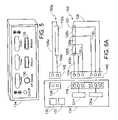
- FIG. 5is a front perspective view of a power supply and control device in accordance with a preferred embodiment of a present invention.
- FIG. 6Ais a diagrammatic view of a system in accordance with a preferred embodiment of a present invention.
- FIG. 6Bis a diagrammatic view of a system in accordance with a preferred embodiment of a present invention.
- FIG. 7is a flow chart of a method in accordance with a preferred embodiment of the present invention.
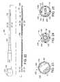
- FIG. 8is a plan view of an energy transmission assembly in accordance with a preferred embodiment of a present invention.
- FIG. 9is a section view taken along line 9 — 9 in FIG. 8 .
- FIG. 10is a section view taken along line 10 — 10 in FIG. 8 .
- FIG. 11is an enlarged view of a portion of the energy transmission assembly illustrated in FIG. 8 .
- FIG. 12is a section view taken along line 12 — 12 in FIG. 11 .
- FIG. 13is a plan view of a clamp in accordance with a preferred embodiment of a present invention.
- FIG. 14is a section view taken along line 14 — 14 in FIG. 13 .
- FIG. 15is a top view of a portion of the clamp illustrated in FIG. 13 .
- FIG. 16is a plan view showing the energy transmission assembly illustrated in FIG. 8 in combination with the clamp illustrated in FIG. 13 .
- FIG. 17is a section view of an energy transmission assembly in accordance with a preferred embodiment of a present invention.
- FIG. 18is a section view taken along line 18 — 18 in FIG. 17 .
- FIG. 19is a section view of an energy transmission assembly in accordance with a preferred embodiment of a present invention.
- FIG. 20is a section view taken along line 20 — 20 in FIG. 19 .
- FIG. 21is a section view of an energy transmission assembly in accordance with a preferred embodiment of a present invention.
- FIG. 22is a plan view of a surgical probe in accordance with a preferred embodiment of a present invention.
- FIG. 23is a section view taken along line 23 — 23 in FIG. 22 .
- FIG. 24is a section view taken along line 24 — 24 in FIG. 22 .
- FIG. 25is a section view taken along line 25 — 25 in FIG. 22 .
- an electrode assembly 100 in accordance with a preferred embodiment of a present inventionincludes an electrode 102 and first and second power supply lines 104 and 106 that are connected to the electrode.
- the electrode assembly 100is configured such that power is supplied to the electrode 102 at at least two locations. The power will preferably, although not necessarily, be supplied to each of the locations simultaneously.
- the electrode 102includes first and second generally cylindrical base portions 108 and 110 and a helical portion 112 .
- the power supply lines 104 and 106are respectively connected to the base portions 108 and 110 by welds 114 and 116 .
- the exemplary electrode 102is preferably a spiral (or “helical”) coil that is relatively flexible.
- the exemplary electrode 102is made of electrically conducting material, like copper alloy, platinum, or stainless steel, or compositions such as drawn-filled tubing (e.g. a copper core with a platinum jacket).
- the electrically conducting materialcan be further coated with platinum-iridium or gold to improve its conduction properties and biocompatibility.
- An exemplary coil electrode configurationis disclosed in U.S. Pat. No. 5,797,905. With respect to the manufacture of a helical electrode, such an electrode may be manufactured by, for example, laser cutting a hypotube ( FIG. 1 ) or winding wire that is either round or rectangular in cross-section into the desired shape ( FIG. 17 ).
- the structural and electrical characteristics of the electrode 102are preferably such that the power supplied to one portion of the electrode will be substantially dissipated before it reaches a portion of the electrode to which power is being independently supplied.
- the lengthis preferably between about 2 cm and 8 cm in those instances where power is supplied at the longitudinal ends and the end to end resistance is about 5 ohm to about 15 ohm.
- the end to end resistanceis about 5 ohm to about 15 ohm.
- about 80% of the power supplied to one of the endswill be dissipated prior to reaching the mid-point of the electrode.
- the diameterpreferably ranges from about 1.5 mm to about 3 mm for cardiovascular applications.
- the wall thickness of the hypotubeis about 0.12 mm, the length is 6.4 cm, the outer diameter is about 2 mm, and the end to end resistance is about 10 ohms.
- the electrodepreferably includes a third base portion at the mid-point between the base portions at the longitudinal ends of the electrode.
- the three power supply linesare respectively connected to the three base portions.
- the length of the electrodepreferably ranges from about 6 cm to about 12 cm and the resistance between adjacent base portions will be about 5 ohm to about 15 ohm and, in a preferred implementation, about 10 ohms.
- the electrodesmay be in the form of solid rings of conductive material, like platinum, or can comprise a conductive material, like platinum-iridium or gold, coated upon an underlying non-conductive support member using conventional coating techniques or an ion beam assisted deposition (IBAD) process. For better adherence, an undercoating of nickel or titanium can be applied.
- the electrodescan also be formed with a conductive ink compound that is pad printed onto an underlying non-conductive support member.
- a preferred conductive ink compoundis a silver-based flexible adhesive conductive ink (polyurethane binder), however other metal-based adhesive conductive inks such as platinum-based, gold-based, copper-based, etc., may also be used to form electrodes. Such inks are more flexible than epoxy-based inks. Power may also be supplied to these alternative electrodes at two or more positions.
- the electrode 102may be carried by a support structure 118 .
- the exemplary support structure 118is a flexible tubular structure which has an outer diameter that is, depending on the diameter of the electrode 102 , typically between about 1.5 mm and about 3 mm.
- the support structure 118 in the illustrated embodiment, which is intended for use in cardiovascular applications,has an outer diameter of about 2 mm.
- Suitable support structure materialsinclude, for example, flexible biocompatible thermoplastic tubing such as unbraided Pebax® material, polyethylene, or polyurethane tubing.
- the support structure 118is provided with a pair of apertures 120 and 122 for the power supply lines 104 and 106 as well as a tip member 124 .
- a plurality of temperature sensorsmay be located on or under the electrode 102 for temperature control purposes.
- two pairs of temperature sensors 126 a / 126 b and 128 a / 128 bare employed. Each of the temperature sensors operate independently of one another. Temperature sensors 126 a and 128 b are located at the longitudinal edges of the electrode 102 , while temperature sensors 126 b and 128 a are spaced a distance equal to about 1 ⁇ 3 of the total electrode length from the respective longitudinal ends of the electrode.
- a third pair of temperature sensorscould be provided in the aforementioned embodiment in which three power supply lines are connected to the electrode.
- a reference thermocouple(not shown) may also be provided on the support structure 118 in spaced relation to the electrode 102 . Signals from the temperature sensors are transmitted to a power supply and control device by way of signal lines 130 .
- the temperature sensors 126 a / 126 b and 128 a / 128 bare preferably located within a linear channel 132 that is formed in the support structure 118 .
- the linear channelmay extend over the entire length of the support structure 118 or only over the portion that carries the electrode (or electrodes) 102 .
- the linear channel 132insures that the temperature sensors will all face in the same direction (e.g. facing tissue) and be arranged in linear fashion. This arrangement results in more accurate temperature readings which, in turn, results in better temperature control. As such, the actual tissue temperature will more accurately correspond to the temperature set by the physician on the power supply and control device, thereby providing the physician with better control of the lesion creation process and reducing the likelihood that embolic materials will be formed.
- Such a channelmay be employed in conjunction with any of the electrode support structures disclosed herein.
- the electrode assembly 100may be used in conjunction with an electrosurgical unit (“ESU”) 134 that supplies and controls power, such RF power.
- ESUelectrosurgical unit
- a suitable ESUis the Model 4810 ESU sold by Boston Scientific Corporation of Natick, Massachusetts.
- the exemplary ESU 134 illustrated in FIG. 5includes a controller 135 , a source of RF power 137 that is controlled by the controller, and a plurality of displays and buttons that are used to set the level of power supplied to the electrode 102 and the temperature at various locations on the electrode.
- the exemplary ESU 134 illustratedis operable in a bipolar mode, where tissue coagulation energy emitted by the electrode 102 is returned through a return electrode 102 a , and a unipolar mode, where the tissue coagulation energy emitted by the electrode is returned through one or more indifferent electrodes (not shown) that are externally attached to the skin of the patient with a patch or one or more electrodes (not shown) that are positioned in the blood pool.
- the return electrode 102 awhich in a bipolar configuration is preferably (but not necessarily) identical to the electrode 102 , may be connected to the ESU 134 by a pair of power return lines 104 a and 106 a .
- the return electrode 102 a and power return lines 104 a and 106 atogether define a return electrode assembly 100 a.
- the ESU 134 in the illustrated implementationis provided with a power output connector 136 and a pair of return connectors 138 .
- the electrode 102is connected to the power output connector 136 by way of the power supply lines 104 and 106 and a power connector 140
- the return electrode 102 ais connected to one of the return connectors 138 by way of the power return lines 104 a and 106 a and a return connector 142 .
- the ESU output and return connectors 136 and 138have different shapes to avoid confusion and the power and return connectors 140 and 142 are correspondingly shaped.
- the power connector 140has a generally circular shape corresponding to the ESU power output connector 136 and the return connector 142 has a generally rectangular shape corresponding to the ESU return connector 138 .
- Signals from the temperature sensors 126 a / 126 b and 128 a / 128 bare transmitted to the ESU 134 by way of the signal lines 130 and the power connector 140 .
- the exemplary ESU 134 illustrated in FIGS. 5 and 6Ais configured to individually power and control a plurality of electrodes (typically relatively short electrodes that are about 10 mm in length). This is sometimes referred to as “multi-channel control” and the ESU 134 preferably includes up to 8 channels.
- the exemplary ESU 134is also configured to individually power and control two or more portions of a single electrode as well as two or more portions of each of a plurality of electrodes during a lesion formation procedure.
- the electrode 102 in the exemplary implementationis divided into two portions for power control purposes—the electrode portion connected to the power supply line 104 on one side of the dash line in FIG. 6A and the electrode portion connected to the power supply line 106 on the other side of the dash line.
- the electrode 102is preferably a continuous, unitary structure.
- the electrode 102is placed adjacent to tissue and power to one portion is controlled by control channel CH 1 and power to the other portion is controlled by control channel CH 2 .
- the poweris preferably, although not necessarily, supplied to both portions simultaneously.
- the above-described power supply/lesion formation methodis illustrated in FIG. 7 .
- the level of power supplied to the electrode 102 by way of the power supply line 104may be controlled based on the temperatures sensed by the temperature sensors 126 a / 126 b
- the level of power supplied to the electrode 102 by way of the power supply line 106may be controlled based on the temperatures sensed by the temperature sensors 128 a / 128 b .
- the level of power supplied to the electrode 102 by way of the power supply line 104would be controlled based on the highest of the two temperatures sensed by the temperature sensors 126 a / 126 b
- the level of power supplied to the electrode 102 by way of the power supply line 106would be controlled based on the highest of the two temperatures sensed by the temperature sensors 128 a / 128 b.
- the amount of power required to coagulate tissuetypically ranges from 5 to 150 w.
- Suitable temperature sensors and power control schemes that are based on sensed temperaturesare disclosed in U.S. Pat. Nos. 5,456,682, 5,582,609 and 5,755,715.
- the temperature sensors 126 b and 128 amay be located on the return electrode 102 a in certain bipolar implementations, such as the exemplary bipolar energy transmission assembly 144 illustrated in FIG. 8 .
- the power control schemewill preferably be the same in that the level of power supplied to the electrode 102 by way of the power supply line 104 would be controlled based on the temperatures sensed by the temperature sensors 126 a / 126 b , while the level of power supplied to the electrode 102 by way of the power supply line 106 would be controlled based on the temperatures sensed the temperature sensors 128 a / 128 b.
- each of the electrodeswill preferably be connected to a respective pair of power supply lines 104 and 106 and include its own set of temperature sensors 126 a / 126 b and 128 a / 128 b .
- Each of the electrodes 102 on the surgical probe 230will also preferably be divided into two portions for power control purposes and the level of power supplied to the each electrode portion by way of the power supply lines 104 would be controlled based on the temperatures sensed by the temperature sensors 126 a / 126 b , while the level of power supplied to the electrode portions by way of the power supply lines 106 would be controlled based on the temperatures sensed by the temperature sensors 128 a / 128 b.
- the electrodes 102may be used in conjunction with a wide variety of electrophysiology devices.
- an energy transmission assemblywhich is an electrophysiology device that may be combined with a conventional surgical tool to form a tissue coagulating device.
- clampsare one example of a surgical tool that may be used in conjunction with energy transmission assemblies in accordance with the present inventions.
- clampincludes, but is not limited to, clamps, clips, forceps, hemostats, and any other surgical device that includes a pair of opposable clamp members that hold tissue, at least one of which is movable relative to the other.
- the clamp membersare connected to a scissors-like arrangement including a pair of handle supporting arms that are pivotably connected to one another.
- the clamp membersare secured to one end of the arms and the handles are secured to the other end.
- Certain clamps that are particularly useful in minimally invasive proceduresalso include a pair of handles and a pair of clamp members.
- the clamp members and handlesare not mounted on the opposite ends of the same arm. Instead, the handles are carried by one end of an elongate housing and the clamp members are carried by the other.
- a suitable mechanical linkage located within the housingcauses the clamp members to move relative to one another in response to movement of the handles.
- the clamp membersmay be linear or have a predefined curvature that is optimized for a particular surgical procedure or portion thereof.
- the clamp membersmay also be rigid or malleable.
- the exemplary energy transmission assemblythat is generally represented by reference numeral 144 in FIGS. 8–12 may be used to covert the conventional clamp 200 illustrated in FIGS. 13–15 into the tissue coagulation device 220 illustrated in FIG. 16 .
- FIGS. 13–15one example of a conventional clamp that may be used in conjunction with the present inventions is generally represented by reference numeral 200 .
- the clamp 200includes a pair of rigid arms 202 and 204 that are pivotably connected to one another by a pin 206 .
- the proximal ends of the arms 202 and 204are respectively connected to a pair handle members 208 and 210 , while the distal ends are respectively connected to a pair of clamp members 212 and 214 .
- the clamp members 212 and 214may be rigid or malleable and, if rigid, may be linear or have a pre-shaped curvature.
- a locking device 216locks the clamp in the closed orientation, and prevents the clamp members 212 and 214 from coming any closer to one another than is illustrated in FIG. 13 , thereby defining a predetermined spacing between the clamp members.
- the clamp 200is also configured for used with a pair of soft, deformable inserts (not shown) that may be removably carried by the clamp members 212 and 214 and allow the clamp to firmly grip a bodily structure without damaging the structure.
- the clamp members 212 and 214are each include a slot 216 that is provided with a sloped inlet area 218 and the inserts include mating structures that are removably friction fit within the slots.
- the present energy transmission assembliesmay be mounted on the clamp members in place of the inserts.
- the exemplary energy transmission assembly 144includes a power transmitting electrode assembly 100 (i.e. an electrode 102 and first and second power supply lines 104 and 106 ) and a return electrode assembly 100 a (i.e. an electrode 102 a and first and second power supply lines 104 a and 106 a ).
- the electrode assemblies 100 and 100 aare carried on respective support structures 118 and 118 a .
- the support structures 118 and 118 aare connected to a flexible cable 146 by a molded plastic junction 148 .
- the first and second power supply lines 104 and 106 and signal lines 130run from the electrode 102 extend through the support structure 118 and the cable 146 to the connector 140 .
- the first and second power return lines 104 a and 106 arun from the electrode 102 a , through the support structure 118 a and the cable 146 to the connector 142 .
- the cable 146is secured to a handle 150 with a strain relief element 152 .
- the exemplary energy transmission assembly 144also includes a pair of base members 154 and 154 a which are used to connect the electrode assemblies 100 and 100 a to the clamp 200 .
- the exemplary energy transmission assemblyis configured such that the electrodes 102 and 102 a will be parallel to one another as well as relatively close to one another (i.e. a spacing of about 1–10 mm) when the clamp 200 is in the closed orientation. Such an arrangement will allow the energy transmission assembly to grip a bodily structure without cutting through the structure. Referring more specifically to FIGS.
- the base member 154includes a main portion 156 , with a groove 158 that is configured to receive the support structure 118 and electrode 102 , and a connector 160 that is configured to removably mate with the slot 216 in the clamp 200 .
- the configuration of the base member 154 ais identical to that of the base member 154 in the illustrated embodiment.
- About 20% of the electrode surfacei.e. about 75° of the 360° circumference) is exposed in the illustrated embodiment.
- Adhesivemay be used to hold the support structure 118 and electrode 102 in place.
- the exemplary connector 160is provided with a relatively thin portion 162 and a relatively wide portion 164 , which may consist of a plurality of spaced members (as shown) or an elongate unitary structure, in order to correspond to the shape of the slot 216 .
- the base members 154 and 154 aare preferably formed from polyurethane.
- the length of the base members in the exemplary energy transmission assemblieswill vary according to the intended application. In the area of cardiovascular treatments, it is anticipated that suitable lengths will range from, but are not limited to, about 4 cm to about 10 cm. In the exemplary implementation, where the electrodes 102 and 102 a are preferably about 6.4 cm, the base members 154 and 154 a will be about 6.6 cm.
- the exemplary energy transmission assembly 144 and clamp 200may be combined to form a tissue coagulation device 220 .
- the electrode assemblies 100 and 100 amay be secured to the clamp members 212 and 214 by the base members 154 and 154 a .
- the coagulation device 220may be used to form a lesion by, for example, positioning the electrode assemblies 100 and 100 a on opposite sides of a tissue structure with the clamp members 212 and 214 .
- Energy from a power supply and control device(such as the ESU 134 illustrated in FIG. 5 ) may be transmitted to both longitudinal ends of the electrode 102 by way of the connector 140 and returned to the power supply and control device by way of the electrode 102 a and connector 142 .
- transmural epicardial lesionsto isolate the sources of focal (or ectopic) atrial fibrillation and, more specifically, the creation of transmural lesions around the pulmonary veins.
- Lesionsmay be created around the pulmonary veins individually or, alternatively, lesions may be created around pairs of pulmonary veins. For example, a first transmural epicardial lesion may be created around the right pulmonary vein pair and a second transmural epicardial lesion may be created around the left pulmonary vein pair. Thereafter, if needed, a linear transmural epicardial lesion may be created between the right and left pulmonary vein pairs.
- a linear transmural lesion that extends from the lesion between the right and left pulmonary vein pairs to the left atrial appendagemay also be formed.
- These linear lesionsmay be formed with the tissue coagulation device 220 by forming a hole in the atria, inserting one of the clamp members (and corresponding electrode assembly) into the atria, and then closing the clamp members along the desired portion of the atria.
- a linear transmural epicardial lesionmay be formed with the surgical probe illustrated in FIG. 22 . It should also be noted that, instead of forming multiple lesions, a single lesion may be formed around all four of the pulmonary veins.
- the exemplary energy transmission assembly 144may be modified in a variety of ways. For example, a layer of Dacron or a Dacron/collagen composite may be placed over the exposed surface of the electrodes 102 and 102 a . This material, when wetted with saline, reduces tissue desiccation and makes current densities more uniform. As such, surface char is avoided and transmural lesion formation is ensured.
- the energy transmitting portion of an exemplary energy transmission assembly 166includes an electrode assembly 100 ′ and a base member 168 that carries an electrode 102 ′ (thereby acting as a support structure) and is configured to be removably slipped over and secured to a clamp member, such as one of the clamp members 212 and 214 .
- the electrode assembly 100 ′is substantially similar to the electrode assembly 100 .
- the electrode 102 ′is in the form of a wound wire (although a laser cut hypotube-type electrode could also be employed here).
- the energy transmission assemblywill be a bipolar arrangement that includes a second generally identical base member and electrode, as is discussed above with reference to FIG. 8 .
- a bipolar energy transmission assemblymay be configured such that the transmitting and return electrodes will be parallel to one another as well as relatively close to one another when the clamp is in the closed orientation in order to allow the energy transmission assembly to grip a bodily structure without cutting through the structure.
- the structure illustrated in FIGS. 17 and 18may be used in combination with an indifferent electrode that is externally attached to the skin of the patient with a patch or one or more electrodes that are positioned in the blood pool.
- the exemplary base member 168is preferably formed from a soft, resilient, low durometer material that is electrically insulating. Suitable materials include polyurethane, silicone and polyurethane/silicone blends having a hardness of between about 20 Shore D and about 72 Shore D.
- the base member 168includes a longitudinally extending aperture 170 into which the clamp member may be inserted.
- the aperture 170should be sized and shaped such that the base member 168 will be forced to stretch when the clamp member is inserted. If, for example, the aperture 170 has the same cross-sectional shape as the clamp member (e.g. both are elliptical), then the aperture should be slightly smaller in their cross-sectional dimensions than the corresponding clamp member.
- the stretching of the apertures 170creates a tight interference fit between the base member 168 and clamp member.
- the aperture 170has a semi-circular cross-section in the exemplary embodiment, the aperture may have a round, rectangular, square or elliptical cross-section, or define any other cross-sectional shape, depending on the particular application.
- the exemplary base member 168also includes a slot 172 that secures the electrode assembly 100 ′ in place.
- the configuration of the slot 172will, of course, depend on the configuration of the electrode assembly that it is holding.
- the illustrated electrode 102 ′is generally cylindrical in shape and the slot 172 has a corresponding arcuate cross-sectional shape.
- the arcis preferably greater than 180 degrees so that the base member 168 will deflect when the electrode 102 ′ is inserted into the slot 172 and then snap back to hold the electrode in place.
- Adhesivemay also be used to secure the electrode 102 ′, especially in those instances where the arc is less than 180 degrees.
- the exemplary base member 168is also provided with a wire aperture 174 , a pair of power line holes 176 and four signal line holes 178 for the temperature sensors 126 a ′/ 126 b ′ and 128 a ′/ 128 b ′.
- the number of power line and signal line holeswill, of course, depend on the configuration of the electrode assembly 100 ′.
- a cable 180provided for the power supply lines 104 and 106 and temperature sensor signal lines 130 .
- Energy transmission assemblies in accordance with the present inventionsmay also be provided with apparatus that cools the tissue during tissue coagulation procedures.
- the tissue cooling apparatus disclosed hereinemploy conductive fluid to cool tissue during coagulation procedures. More specifically, and as described below and in U.S. application Ser. No. 09/761,981, which is entitled “Fluid Cooled Apparatus For Supporting Diagnostic And Therapeutic Elements In Contact With Tissue” and incorporated herein by reference, heat from the tissue being coagulated is transferred to ionic fluid to cool the tissue while energy is transferred from an electrode or other energy transmission device to the tissue through the fluid by way of ionic transport.
- the conductive fluidmay be pumped through the tissue cooling apparatus ( FIGS.
- tissue cooling apparatusmay be saturated with the fluid prior to use ( FIG. 21 ).
- cooling tissue during a coagulation procedurefacilitates the formation of lesions that are wider and deeper than those that could be realized with an otherwise identical device which lacks tissue cooling apparatus.
- tissue cooling apparatuswill be associated with both the transmitting electrode and the return electrode in a bipolar implementation.
- the energy transmitting portion of an exemplary energy transmission assembly 166 ′includes an electrode 102 ′ and a base member 168 ′ that carries the electrode and is configured to be removably secured to a clamp member, such as one of the clamp members 212 and 214 .
- a tissue cooling apparatus 182is also provided.
- the energy transmission assemblywill be a bipolar arrangement that includes a second generally identical base member, electrode and cooling apparatus, as is discussed above with reference to FIG. 8 .
- Such a bipolar energy transmission assemblymay be configured such that the transmitting and return electrodes will be parallel to one another as well as relatively close to one another when the clamp is in the closed orientation in order to allow the energy transmission assembly to grip a bodily structure without cutting through the structure.
- the structure illustrated in FIGS. 19 and 20may be used in combination with an indifferent electrode that is externally attached to the skin of the patient with a patch or one or more electrodes that are positioned in the blood pool.
- the aperture 170 ′has an elliptical cross-section in the exemplary embodiment, the apertures may have a round, rectangular, square or semi-circular cross-section, or define any other cross-sectional shape, depending on the particular application.
- the exemplary tissue cooling apparatus 182includes a nanoporous outer casing 184 through which ionic fluid (represented by arrows F) is transferred.
- the ionic fluidpreferably flows from one longitudinal end of the tissue cooling apparatus 182 to the other.
- the outer casing 184is secured to the base member 168 ′ over the electrode 102 ′ such that a fluid transmission space 186 is defined therebetween. More specifically, the proximal and distal ends of the outer casing 184 are secured to the base member 168 ′ with anchoring devices (not shown) such as lengths of heat shrink tubing, Nitinol tubing or other mechanical devices that form an interference fit between the casing and the base member. Adhesive bonding is another method of securing the outer casing 184 to the base member 168 ′.
- the fluid transmission spacewill typically be about 0.5 mm to about 2.0 mm high and slightly wider than the associated electrode 102 ′.
- the ionic fluidis supplied under pressure from a fluid source (not shown) by way of a supply line 188 and is returned to the source by way of a return line 190 in the exemplary implementation illustrated in FIGS. 19 and 20 .
- the supply line 188is connected to a fluid lumen 192 that runs from the proximal end of the base member 168 ′ to the distal region of the outer casing 184 .
- the fluid lumen 192is connected to the fluid transmission space 186 by an aperture 194 .
- the electrically conductive ionic fluidpreferably possesses a low resistivity to decrease ohmic loses, and thus ohmic heating effects, within the outer casing 184 .
- the composition of the electrically conductive fluidcan vary.
- the fluidis a hypertonic saline solution, having a sodium chloride concentration at or near saturation, which is about 5% to about 25% weight by volume.
- Hypertonic saline solutionhas a relatively low resistivity of only about 5 ohm-cm, as compared to blood resistivity of about 150 ohm-cm and myocardial tissue resistivity of about 500 ohm-cm.
- the ionic fluidcan be a hypertonic potassium chloride solution.
- a suitable inlet temperature for epicardial applications(the temperature will, of course, rise as heat is transferred to the fluid) is about 0 to 25° C. with a constant flow rate of about 2 to 20 ml/min.
- the flow rate required for endocardial applications where blood is presentwould be about three-fold higher (i.e. 6 to 60 ml/min.). Should applications so require, a flow rate of up to 100 ml/min. may be employed.
- a volume of fluid between about 200 and 500 ml within the bagwill remain at room temperature (about 22° C.) when the flow rate is between about 2 ml/min. and 20 ml/min.
- the flexible bagshould include enough fluid to complete the procedure. 160 ml would, for example, be required for a 20 minute procedure where the flow rate was 8 ml/min.
- the fluid pressure within the outer casing 184should be about 30 mm Hg in order to provide a structure that will resiliently conform to the tissue surface in response to a relatively small force normal to the tissue. Pressures above about 100 mm Hg will cause the outer casing 184 to become too stiff to properly conform to the tissue surface. For that reason, the flow resistance to and from the outer casing 184 should be relatively low.
- the pores in the nanoporous outer casing 184allow the transport of ions contained in the fluid through the casing and into contact with tissue.
- the ionic fluidestablishes an electrically conductive path through the outer casing 184 to the tissue being coagulated.
- Regenerated cellulose membrane materialstypically used for blood oxygenation, dialysis or ultrafiltration, are a suitable nanoporous material for the outer casing 184 .
- the thickness of the materialshould be about 0.002 to 0.005 inch.
- regenerated celluloseis electrically non-conductive, the relatively small pores of this material allow effective ionic transport in response to the applied RF field. At the same time, the relatively small pores prevent transfer of macromolecules through the material, so that pressure driven liquid perfusion is less likely to accompany the ionic transport, unless relatively high pressure conditions develop within the outer casing 184 .
- Hydro-FluoroTM materialwhich is disclosed in U.S. Pat. No. 6,395,325, is another material that may be used.
- Materialssuch as nylons (with a softening temperature above 100° C.), PTFE, PEI and PEEK that have nanopores created through the use of lasers, electrostatic discharge, ion beam bombardment or other processes may also be used. Such materials would preferably include a hydrophilic coating.
- Nanoporous materialsmay also be fabricated by weaving a material (such as nylon, polyester, polyethylene, polypropylene, fluorocarbon, fine diameter stainless steel, or other fiber) into a mesh having the desired pore size and porosity. These materials permit effective passage of ions in response to the applied RF field.
- the electrical resistivity of the outer casingcan be controlled by specifying the pore size of the material, the porosity of the material, and the water adsorption characteristics (hydrophilic versus hydrophobic) of the material. A detailed discussion of these characteristics is found in U.S. Pat. No. 5,961,513.
- a suitable electrical resistivity for epicardial and endocardial lesion formationis about 1 to 3000 ohm-cm measured wet.
- ionic transportcreates a continuous virtual electrode at the tissue interface.
- the virtual electrodeefficiently transfers RF energy without need for an electrically conductive metal surface. Pore diameters smaller than about 0.1 ⁇ m retain macromolecules, but allow ionic transfer through the pores in response to the applied RF field. With smaller pore diameters, pressure driven liquid perfusion through the pores is less likely to accompany the ionic transport, unless relatively high pressure conditions develop within the outer casing 184 Larger pore diameters (up to 8 ⁇ m) can also be used to permit ionic current flow across the membrane in response to the applied RF field.
- a pore diameter of 1 to 5 ⁇ mis suitable for epicardial and endocardial lesion formation. Where a larger pore diameter is employed, thereby resulting in significant fluid transfer through the porous region, a saline solution having a sodium chloride concentration of about 0.9% weight by volume would be preferred.
- porositywhich represents the volumetric percentage of the outer casing 184 that is composed of pores and not occupied by the casing material
- the magnitude of the porosityaffects electrical resistance.
- Low-porosity materialshave high electrical resistivity, whereas high-porosity materials have low electrical resistivity.
- the porosity of the outer casing 184should be at least 1% for epicardial and endocardial applications employing a 1 to 5 ⁇ m pore diameter.
- hydrophilic materialsare generally preferable because they possess a greater capacity to provide ionic transfer of RF energy without significant liquid flow through the material.
- an exemplary energy transmission assembly 166 ′′includes a base member 168 ′′ that carries an electrode 102 ′ and a tissue cooling apparatus 196 .
- the tissue cooling apparatus 196consists of a wettable fluid retention element 198 that is simply saturated with ionic fluid (such as saline) prior to use, as opposed to having the fluid pumped through the apparatus in the manner described above with reference to FIGS. 19 and 20 .
- the electrode 102 ′is carried within the fluid retention element 198 .
- the energy transmission assembly 166 ′′ illustrated in FIG. 21may be provided in both bipolar and unipolar implementations.
- Suitable materials for the fluid retention element 198include biocompatible fabrics commonly used for vascular patches (such as woven Dacron®), open cell foam materials, hydrogels, nanoporous balloon materials (with very slow fluid delivery to the surface), and hydrophilic nanoporous materials.
- the effective electrical resistivity of the fluid retention element 198 when wetted with 0.9% saline (normal saline)should range from about 1 ⁇ -cm to about 2000 ⁇ -cm.
- a preferred resistivity for epicardial and endocardial proceduresis about 1000 ⁇ -cm.
- the energy transmission assemblymay be permanently secured to a clamp or other device.
- the base membermay, if desired, be configured to be secured to both clamp members of a single clamp simultaneously instead on one clamp member.
- a surgical probe 230 in accordance with a preferred embodiment of a present inventionincludes a relatively short shaft 232 , a shaft distal section 234 and a handle 234 .
- the shaft 232consists of a hypotube 238 , which is either rigid or relatively stiff, and an outer polymer tubing 240 over the hypotube.
- the handle 236preferably consists of two molded handle halves and is provided with strain relief element 242 .
- the shaft 232 in the illustrated embodimentmay be from 4 inches to 18 inches in length and is preferably 6 inches to 8 inches.
- the distal section 234which is preferably either malleable, somewhat flexible or some combination thereof, may be from 1 inch to 10 inches in length and is preferably 2 to 3 inches.
- a plurality of electrode assemblies 100including electrodes 102 (or 102 ′) and power supply lines 104 and 106 , are carried on a support structure 118 .
- a tissue cooling apparatussuch as those disclosed in U.S. application Ser. No. 09/761,981, may be positioned over the electrodes 102 if desired.
- the phrase “relatively stiff”means that the shaft (or distal section or other structural element) is either rigid, malleable, or somewhat flexible.
- a rigid shaftcannot be bent.
- a malleable shaftis a shaft that can be readily bent by the physician to a desired shape, without springing back when released, so that it will remain in that shape during the surgical procedure.
- the stiffness of a malleable shaftmust be low enough to allow the shaft to be bent, but high enough to resist bending when the forces associated with a surgical procedure are applied to the shaft.
- a somewhat flexible shaftwill bend and spring back when released. However, the force required to bend the shaft must be substantial.
- Rigid and somewhat flexible shaftsare preferably formed from stainless steel, while malleable shafts are formed from annealed stainless steel.
- One method of quantifying the flexibility of a shaftis to look at the deflection of the shaft when one end is fixed in cantilever fashion and a force normal to the longitudinal axis of the shaft is applied somewhere between the ends.
- a relatively stiff 2 inch shaft(either malleable or somewhat flexible) would have a bending modulus of at least approximately 1 lb.-in. 2
- a relatively stiff 2 inch shaftwill have a bending modulus of between approximately 3 lb.-in. 2 and approximately 50 lb.-in. 2 .
- 2 inch piece of a conventional catheter shafttypically has bending modulus between approximately 0.1 lb.-in. 2 and approximately 0.3 lb.-in. 2 . It should be noted that the bending modulus ranges discussed here are primarily associated with initial deflection.
- the bending modulus rangesare based on the amount of force, applied at and normal to the free end of the longitudinal axis of the cantilevered shaft, that is needed to produce 1 inch of deflection from an at rest (or no deflection) position.
- the deflection of a shaftdepends on the composition of the shaft as well as its moment of inertia.
- the shaftcould be made of elastic material, plastic material, elasto-plastic material or a combination thereof.
- the force required to bend a relatively stiff 2 inch long shaftshould be in the range of approximately 1.5 lbs. to approximately 12 lbs.
- the force required to bend a 2 inch piece of conventional catheter shaftshould be between approximately 0.2 lb. to 0.25 lb.
- such force valuesconcern the amount of force, applied at and normal to the free end of the longitudinal axis of the cantilevered shaft, that is needed to produce 1 inch of deflection from an at rest (or no deflection) position.
- Ductile materialsare preferable in many applications because such materials can deform plastically before failure due to fracturing.
- Materialsare classified as either ductile or brittle, based upon the percentage of elongation when the fracture occurs. A material with more than 5 percent elongation prior to fracture is generally considered ductile, while a material with less than 5 percent elongation prior to fracture is generally considered brittle.
- Material ductilitycan be based on a comparison of the cross sectional area at fracture relative to the original cross area. This characteristic is not dependent on the elastic properties of the material.
- the shaftcould be a mechanical component similar to shielded (metal spiral wind jacket) conduit or flexible Loc-Line®, which is a linear set of interlocking ball and socket linkages that can have a center lumen. These would be hinge-like segmented sections linearly assembled to make the shaft.
- the hypotube 238may be a heat treated malleable hypotube. By selectively heat treating certain portions of the hypotube, one section of the hypotube can be made more malleable than the other.
- the outer tubing 240may be formed from Pebax® material, polyurethane, or other suitable materials.
- the distal section 234can be either somewhat flexible, in that it will conform to a surface against which it is pressed and then spring back to its original shape when removed from the surface, malleable, or some combination thereof.
- a bending modulus of between 3 lb.-in. 2 and 50 lb.-in. 2is preferred.
- the distal section 234includes a malleable proximal portion and a flexible distal portion. Although the relative lengths of the portions may vary to suit particular applications, the malleable proximal portion and a flexible distal portion are equal in length in the illustrated embodiment.
- the exemplary malleable portionincludes a mandrel 242 made of a suitably malleable material, such as annealed stainless steel or beryllium copper, that may be fixed directly within the distal end of the shaft's hypotube 238 and secured by, for example, soldering, spot welding or adhesives. Sufficient space should be provided to allow the power supply lines 104 and 106 and the temperature sensor signal lines 130 to pass.
- An insulating sleeve 244is placed over the mandrel 242 to protects the power supply lines 104 and 106 and the temperature sensor signal lines 130 .
- the insulating sleeve 244is preferably formed from Pebax® material, polyurethane, or other suitable materials.
- a spring member 246which is preferably either a solid flat wire spring (as shown), a round wire, or a three leaf flat wire Nitinol spring, is connected to the distal end of the mandrel 242 with a crimp tube or other suitable instrumentality.
- the distal end of the spring member 246is connected to a tip member 248 by, for example, soldering, spot welding or adhesives.
- Other spring membersformed from materials such as 17-7 or carpenter's steel, may also be used.
- the spring member 246is also enclosed within the insulating sleeve 244 .
- the spring member 246may be pre-stressed so that the distal tip is pre-bent into a desired shape.
- the distal section 234may be formed by a hypotube that is simply a continuation of the shaft hypotube 238 covered by a continuation of the outer tubing 240 .
- the distal end hypotubecan also be a separate element connected to the shaft hypotube 238 , if it is desired that the distal end hypotube have different stiffness (or bending) properties than the shaft hypotube.
- the distal section 234may be made malleable from end to end by eliminating the spring member 246 and extending the malleable mandrel 242 to the tip member 248 .
- the distal section 234may be made flexible from end to end by eliminating the malleable mandrel 242 and extending the spring member 246 from the hypotube 238 to the tip member 248 .
- the power supply lines 104 and 106 and temperature sensor signal lines 130 associated with each electrode 102pass through the distal section 234 and shaft 232 and are connected to a PC board 250 in the handle 236 .
- the handlealso includes a port 252 that is configured to receive a connector cable (not shown) the connects the PC board 250 (and, therefore, the electrode assemblies 100 ) to the ESU 134 or other power supply and control device.
Landscapes
- Health & Medical Sciences (AREA)
- Life Sciences & Earth Sciences (AREA)
- Engineering & Computer Science (AREA)
- Surgery (AREA)
- Animal Behavior & Ethology (AREA)
- General Health & Medical Sciences (AREA)
- Nuclear Medicine, Radiotherapy & Molecular Imaging (AREA)
- Veterinary Medicine (AREA)
- Biomedical Technology (AREA)
- Public Health (AREA)
- Heart & Thoracic Surgery (AREA)
- Molecular Biology (AREA)
- Physics & Mathematics (AREA)
- Medical Informatics (AREA)
- Otolaryngology (AREA)
- Plasma & Fusion (AREA)
- Radiology & Medical Imaging (AREA)
- Electromagnetism (AREA)
- Surgical Instruments (AREA)
- Apparatus Associated With Microorganisms And Enzymes (AREA)
- Immobilizing And Processing Of Enzymes And Microorganisms (AREA)
- Hybrid Cells (AREA)
- Electrotherapy Devices (AREA)
- Measurement And Recording Of Electrical Phenomena And Electrical Characteristics Of The Living Body (AREA)
Abstract
Description
- I. Electrodes, Temperature Sensing and Power Control
- II. Energy Transmission Assemblies
- III. Surgical Probes
The section titles and overall organization of the present detailed description are for the purpose of convenience only and are not intended to limit the present inventions.
I. Electrodes, Temperature Sensing and Power Control
σ=WX2(3L−X)/6EI
- W is the force applied normal to the longitudinal axis of the shaft,
- L is the length of the shaft,
- X is the distance between the fixed end of the shaft and the applied force,
- E is the modulous of elasticity, and
- I is the moment of inertia of the shaft.
When the force is applied to the free end of the shaft, deflection can be expressed as follows:
σ=WL3/3EI
Assuming that W and L are equal when comparing different shafts, the respective E and I values will determine how much the shafts will bend. In other words, the stiffness of a shaft is a function of the product of E and I. This product is referred to herein as the “bending modulus.” E is a property of the material that forms the shaft, while I is a function of shaft geometry, wall thickness, etc. Therefore, a shaft formed from relatively soft material can have the same bending modulus as a shaft formed from relatively hard material, if the moment of inertia of the softer shaft is sufficiently greater than that of the harder shaft.
Claims (36)
Priority Applications (14)
| Application Number | Priority Date | Filing Date | Title |
|---|---|---|---|
| US10/255,025US7674258B2 (en) | 2002-09-24 | 2002-09-24 | Electrophysiology electrode having multiple power connections and electrophysiology devices including the same |
| AT03756823TATE318116T1 (en) | 2002-09-24 | 2003-09-16 | ELECTROPHYSIOLOGICAL ELECTRODE WITH SEVERAL ENERGY SUPPLY LINES |
| EP03756823AEP1542604B1 (en) | 2002-09-24 | 2003-09-16 | Electrophysiology electrode having multiple power connections |
| JP2004540099AJP2006500169A (en) | 2002-09-24 | 2003-09-16 | Electrophysiological electrode having a plurality of power connections and electrophysiological device comprising the same |
| PCT/US2003/029270WO2004028386A1 (en) | 2002-09-24 | 2003-09-16 | Electrophysiology electrode having multiple power connections and electrophysiology devices including the same |
| CA002499366ACA2499366A1 (en) | 2002-09-24 | 2003-09-16 | Electrophysiology electrode having multiple power connections and electrophysiology devices including the same |
| ES03756823TES2258728T3 (en) | 2002-09-24 | 2003-09-16 | ELECTRODE FOR ELECTROPHYSIOLOGY THAT HAS MULTIPLE POWER CONNECTIONS. |
| AU2003299076AAU2003299076A1 (en) | 2002-09-24 | 2003-09-16 | Electrophysiology electrode having multiple power connections and electrophysiology devices including the same |
| DE60303679TDE60303679T2 (en) | 2002-09-24 | 2003-09-16 | ELECTROPHYSIOLOGICAL ELECTRODE WITH SEVERAL POWER SUPPLY LINES |
| US12/688,618US8518038B2 (en) | 2002-09-24 | 2010-01-15 | Electrophysiology electrode having multiple power connections and electrophysiology devices including the same |
| US12/971,774US9072522B2 (en) | 2001-12-04 | 2010-12-17 | Adjustable clamp systems and methods |
| US14/010,093US9427278B2 (en) | 2002-09-24 | 2013-08-26 | Electrophysiology electrode having multiple power connections and electrophysiology devices including the same |
| US14/740,514US9445864B2 (en) | 2001-12-04 | 2015-06-16 | Adjustable clamp systems and methods |
| US15/271,078US10398495B2 (en) | 2001-12-04 | 2016-09-20 | Adjustable clamp systems and methods |
Applications Claiming Priority (1)
| Application Number | Priority Date | Filing Date | Title |
|---|---|---|---|
| US10/255,025US7674258B2 (en) | 2002-09-24 | 2002-09-24 | Electrophysiology electrode having multiple power connections and electrophysiology devices including the same |
Related Child Applications (1)
| Application Number | Title | Priority Date | Filing Date |
|---|---|---|---|
| US12/688,618ContinuationUS8518038B2 (en) | 2002-09-24 | 2010-01-15 | Electrophysiology electrode having multiple power connections and electrophysiology devices including the same |
Publications (2)
| Publication Number | Publication Date |
|---|---|
| US20040059325A1 US20040059325A1 (en) | 2004-03-25 |
| US7674258B2true US7674258B2 (en) | 2010-03-09 |
Family
ID=31993429
Family Applications (3)
| Application Number | Title | Priority Date | Filing Date |
|---|---|---|---|
| US10/255,025Expired - Fee RelatedUS7674258B2 (en) | 2001-12-04 | 2002-09-24 | Electrophysiology electrode having multiple power connections and electrophysiology devices including the same |
| US12/688,618Expired - Fee RelatedUS8518038B2 (en) | 2002-09-24 | 2010-01-15 | Electrophysiology electrode having multiple power connections and electrophysiology devices including the same |
| US14/010,093Expired - LifetimeUS9427278B2 (en) | 2002-09-24 | 2013-08-26 | Electrophysiology electrode having multiple power connections and electrophysiology devices including the same |
Family Applications After (2)
| Application Number | Title | Priority Date | Filing Date |
|---|---|---|---|
| US12/688,618Expired - Fee RelatedUS8518038B2 (en) | 2002-09-24 | 2010-01-15 | Electrophysiology electrode having multiple power connections and electrophysiology devices including the same |
| US14/010,093Expired - LifetimeUS9427278B2 (en) | 2002-09-24 | 2013-08-26 | Electrophysiology electrode having multiple power connections and electrophysiology devices including the same |
Country Status (9)
| Country | Link |
|---|---|
| US (3) | US7674258B2 (en) |
| EP (1) | EP1542604B1 (en) |
| JP (1) | JP2006500169A (en) |
| AT (1) | ATE318116T1 (en) |
| AU (1) | AU2003299076A1 (en) |
| CA (1) | CA2499366A1 (en) |
| DE (1) | DE60303679T2 (en) |
| ES (1) | ES2258728T3 (en) |
| WO (1) | WO2004028386A1 (en) |
Cited By (7)
| Publication number | Priority date | Publication date | Assignee | Title |
|---|---|---|---|---|
| US20100121322A1 (en)* | 2002-09-24 | 2010-05-13 | Endoscopic Technologies, Inc. (Estech) | Electrophysiology electrode having multiple power connections and electrophysiology devices including the same |
| US20100243639A1 (en)* | 2009-03-24 | 2010-09-30 | Beyke Gregory L | Flexible horizontal electrode pipe |
| US20110152860A1 (en)* | 2001-12-04 | 2011-06-23 | Estech, Inc. (Endoscopic Technologies, Inc.) | Adjustable clamp systems and methods |
| US9757185B2 (en) | 2012-11-29 | 2017-09-12 | Gyrus Acmi, Inc. | Quadripolar forceps |
| US10357305B2 (en) | 2014-03-26 | 2019-07-23 | Venclose, Inc. | Venous disease treatment |
| US11229479B2 (en) | 2009-12-18 | 2022-01-25 | Atricure, Inc. | Adjustable clamp systems and methods |
| US11678928B2 (en) | 2019-01-10 | 2023-06-20 | Atricure, Inc. | Surgical clamp |
Families Citing this family (71)
| Publication number | Priority date | Publication date | Assignee | Title |
|---|---|---|---|---|
| US12121289B2 (en)* | 2008-05-09 | 2024-10-22 | Atricure, Inc. | Conduction block systems and methods |
| US7753908B2 (en)* | 2002-02-19 | 2010-07-13 | Endoscopic Technologies, Inc. (Estech) | Apparatus for securing an electrophysiology probe to a clamp |
| US7785324B2 (en)* | 2005-02-25 | 2010-08-31 | Endoscopic Technologies, Inc. (Estech) | Clamp based lesion formation apparatus and methods configured to protect non-target tissue |
| US6932816B2 (en)* | 2002-02-19 | 2005-08-23 | Boston Scientific Scimed, Inc. | Apparatus for converting a clamp into an electrophysiology device |
| US7357800B2 (en)* | 2003-02-14 | 2008-04-15 | Boston Scientific Scimed, Inc. | Power supply and control apparatus and electrophysiology systems including the same |
| US20050119653A1 (en)* | 2003-12-02 | 2005-06-02 | Swanson David K. | Surgical methods and apparatus for forming lesions in tissue and confirming whether a therapeutic lesion has been formed |
| US8002770B2 (en) | 2003-12-02 | 2011-08-23 | Endoscopic Technologies, Inc. (Estech) | Clamp based methods and apparatus for forming lesions in tissue and confirming whether a therapeutic lesion has been formed |
| US7549988B2 (en)* | 2004-08-30 | 2009-06-23 | Boston Scientific Scimed, Inc. | Hybrid lesion formation apparatus, systems and methods |
| US7862561B2 (en)* | 2005-01-08 | 2011-01-04 | Boston Scientific Scimed, Inc. | Clamp based lesion formation apparatus with variable spacing structures |
| US7727231B2 (en) | 2005-01-08 | 2010-06-01 | Boston Scientific Scimed, Inc. | Apparatus and methods for forming lesions in tissue and applying stimulation energy to tissue in which lesions are formed |
| US7776033B2 (en)* | 2005-01-08 | 2010-08-17 | Boston Scientific Scimed, Inc. | Wettable structures including conductive fibers and apparatus including the same |
| US7892228B2 (en)* | 2005-02-25 | 2011-02-22 | Boston Scientific Scimed, Inc. | Dual mode lesion formation apparatus, systems and methods |
| US7678107B2 (en)* | 2005-03-10 | 2010-03-16 | Boston Scientific Scimed, Inc. | Medical needles and electrodes with improved bending stiffness |
| US20070062546A1 (en)* | 2005-06-02 | 2007-03-22 | Viswanathan Raju R | Electrophysiology catheter and system for gentle and firm wall contact |
| US7879030B2 (en)* | 2005-07-27 | 2011-02-01 | St. Jude Medical, Atrial Fibrillation Division, Inc. | Multipolar, virtual-electrode catheter with at least one surface electrode and method for ablation |
| US20080215050A1 (en)* | 2007-03-02 | 2008-09-04 | Ethicon Endo-Surgery, Inc. | Tissue engaging hemostasis device |
| EP2231060B1 (en)* | 2007-12-10 | 2015-05-27 | Medtronic Ablation Frontiers LLC | Ablation catheter |
| US20100036294A1 (en) | 2008-05-07 | 2010-02-11 | Robert Mantell | Radially-Firing Electrohydraulic Lithotripsy Probe |
| WO2009152352A2 (en)* | 2008-06-13 | 2009-12-17 | Aspen Medtech, Inc. | Shockwave balloon catheter system |
| US9072534B2 (en) | 2008-06-13 | 2015-07-07 | Shockwave Medical, Inc. | Non-cavitation shockwave balloon catheter system |
| US10702293B2 (en) | 2008-06-13 | 2020-07-07 | Shockwave Medical, Inc. | Two-stage method for treating calcified lesions within the wall of a blood vessel |
| US9679499B2 (en)* | 2008-09-15 | 2017-06-13 | Immersion Medical, Inc. | Systems and methods for sensing hand motion by measuring remote displacement |
| US9180280B2 (en)* | 2008-11-04 | 2015-11-10 | Shockwave Medical, Inc. | Drug delivery shockwave balloon catheter system |
| US9044618B2 (en) | 2008-11-05 | 2015-06-02 | Shockwave Medical, Inc. | Shockwave valvuloplasty catheter system |
| WO2013039829A1 (en)* | 2011-09-13 | 2013-03-21 | Stryker Corporation | Vaso-occlusive device |
| US8574247B2 (en) | 2011-11-08 | 2013-11-05 | Shockwave Medical, Inc. | Shock wave valvuloplasty device with moveable shock wave generator |
| US9642673B2 (en) | 2012-06-27 | 2017-05-09 | Shockwave Medical, Inc. | Shock wave balloon catheter with multiple shock wave sources |
| AU2013300176B2 (en) | 2012-08-06 | 2017-08-17 | Shockwave Medical, Inc. | Low profile electrodes for an angioplasty shock wave catheter |
| CA2881184C (en) | 2012-08-06 | 2019-06-04 | Shockwave Medical, Inc. | Shockwave catheter |
| US9554815B2 (en) | 2012-08-08 | 2017-01-31 | Shockwave Medical, Inc. | Shockwave valvuloplasty with multiple balloons |
| US9138249B2 (en) | 2012-08-17 | 2015-09-22 | Shockwave Medical, Inc. | Shock wave catheter system with arc preconditioning |
| US9522012B2 (en) | 2012-09-13 | 2016-12-20 | Shockwave Medical, Inc. | Shockwave catheter system with energy control |
| US9333000B2 (en) | 2012-09-13 | 2016-05-10 | Shockwave Medical, Inc. | Shockwave catheter system with energy control |
| US20140128858A1 (en)* | 2012-11-08 | 2014-05-08 | Covidien Lp | Systems and methods for performing endometrial ablation |
| CA3075128C (en) | 2013-03-11 | 2022-07-19 | Northgate Technologies Inc. | Unfocused electrohydraulic lithotripter |
| WO2015042906A1 (en)* | 2013-09-29 | 2015-04-02 | Covidien Lp | Medical treatment devices having adjustable length and/or diameter |
| CN104510529B (en)* | 2013-09-29 | 2017-01-18 | 柯惠有限合伙公司 | Medical treatment device adjustable in length and/or diameter |
| WO2015042900A1 (en)* | 2013-09-29 | 2015-04-02 | Covidien Lp | Medical treatment devices having adjustable length and/or diameter |
| CN104510527B (en)* | 2013-09-29 | 2017-04-12 | 柯惠有限合伙公司 | Medical devices with adjustable length and/or diameter |
| US9730715B2 (en) | 2014-05-08 | 2017-08-15 | Shockwave Medical, Inc. | Shock wave guide wire |
| WO2017087195A1 (en) | 2015-11-18 | 2017-05-26 | Shockwave Medical, Inc. | Shock wave electrodes |
| US10226265B2 (en) | 2016-04-25 | 2019-03-12 | Shockwave Medical, Inc. | Shock wave device with polarity switching |
| US10772566B2 (en) | 2016-05-17 | 2020-09-15 | Biosense Weber (Israel) Ltd. | Multi-electrode catheter spine and method of making the same |
| AU2017339980B2 (en) | 2016-10-06 | 2022-08-18 | Shockwave Medical, Inc. | Aortic leaflet repair using shock wave applicators |
| US10357264B2 (en) | 2016-12-06 | 2019-07-23 | Shockwave Medical, Inc. | Shock wave balloon catheter with insertable electrodes |
| US10441300B2 (en) | 2017-04-19 | 2019-10-15 | Shockwave Medical, Inc. | Drug delivery shock wave balloon catheter system |
| US11020135B1 (en) | 2017-04-25 | 2021-06-01 | Shockwave Medical, Inc. | Shock wave device for treating vascular plaques |
| US10966737B2 (en) | 2017-06-19 | 2021-04-06 | Shockwave Medical, Inc. | Device and method for generating forward directed shock waves |
| US12403306B2 (en) | 2017-10-23 | 2025-09-02 | Cardiac Pacemakers, Inc. | Electric field shaping leads for treatment of cancer |
| US10709462B2 (en) | 2017-11-17 | 2020-07-14 | Shockwave Medical, Inc. | Low profile electrodes for a shock wave catheter |
| JP7538039B2 (en) | 2018-01-10 | 2024-08-21 | アトリキュア, インコーポレイテッド | Devices and accessories for punch-type endoscopic access and ablation systems |
| EP3809988B1 (en) | 2018-06-21 | 2023-06-07 | Shockwave Medical, Inc. | System for treating occlusions in body lumens |
| CN113727753B (en) | 2019-04-22 | 2024-09-13 | 波士顿科学国际有限公司 | Electrical stimulation devices for cancer treatment |
| WO2020219339A1 (en) | 2019-04-22 | 2020-10-29 | Boston Scientific Scimed, Inc. | Combination electrical and chemotherapeutic treatment of cancer |
| US11607542B2 (en) | 2019-04-23 | 2023-03-21 | Boston Scientific Scimed, Inc. | Electrical stimulation for cancer treatment with internal and external electrodes |
| WO2021061451A1 (en) | 2019-09-24 | 2021-04-01 | Shockwave Medical, Inc. | Lesion crossing shock wave catheter |
| WO2021061523A1 (en) | 2019-09-24 | 2021-04-01 | Shockwave Medical, Inc. | System for treating thrombus in body lumens |
| EP4512350A3 (en) | 2019-09-24 | 2025-05-07 | Shockwave Medical, Inc. | Low profile electrodes for a shock wave catheter |
| CN115515674A (en) | 2020-02-24 | 2022-12-23 | 波士顿科学国际有限公司 | Systems and methods for treating pancreatic cancer |
| US11992232B2 (en) | 2020-10-27 | 2024-05-28 | Shockwave Medical, Inc. | System for treating thrombus in body lumens |
| US12232755B2 (en) | 2020-12-11 | 2025-02-25 | Shockwave Medical, Inc. | Lesion crossing shock wave catheter |
| US12023098B2 (en) | 2021-10-05 | 2024-07-02 | Shockwave Medical, Inc. | Lesion crossing shock wave catheter |
| GB202117529D0 (en)* | 2021-12-03 | 2022-01-19 | Agco Int Gmbh | Mobile machine and method |
| US12290268B2 (en) | 2023-03-31 | 2025-05-06 | Shockwave Medical, Inc. | Shockwave catheters for treating rhinosinusitis |
| US12035932B1 (en) | 2023-04-21 | 2024-07-16 | Shockwave Medical, Inc. | Intravascular lithotripsy catheter with slotted emitter bands |
| US12220141B2 (en) | 2023-06-29 | 2025-02-11 | Shockwave Medical, Inc. | Catheter system with independently controllable bubble and arc generation |
| US20250064471A1 (en)* | 2023-08-24 | 2025-02-27 | Shockwave Medical, Inc. | Lithotripsy catheters having electrodes formed in metallization layers |
| US12426904B2 (en) | 2023-11-17 | 2025-09-30 | Shockwave Medical, Inc. | Intravascular lithotripsy catheter with oscillating impactor |
| US12402899B2 (en) | 2023-11-30 | 2025-09-02 | Shockwave Medical, Inc. | Systems, devices, and methods for generating shock waves in a forward direction |
| US12433620B2 (en) | 2024-02-23 | 2025-10-07 | Shockwave Medical, Inc. | Locus emitter shock wave catheter devices with increased longevity and higher sonic output |
| US12178458B1 (en) | 2024-05-16 | 2024-12-31 | Shockwave Medical, Inc. | Guidewireless shock wave catheters |
Citations (79)
| Publication number | Priority date | Publication date | Assignee | Title |
|---|---|---|---|---|
| US4685459A (en) | 1985-03-27 | 1987-08-11 | Fischer Met Gmbh | Device for bipolar high-frequency coagulation of biological tissue |
| US4834090A (en) | 1987-03-02 | 1989-05-30 | Moore J Paul | Suture boot |
| US5190541A (en) | 1990-10-17 | 1993-03-02 | Boston Scientific Corporation | Surgical instrument and method |
| US5250072A (en) | 1990-12-10 | 1993-10-05 | Jain Krishna M | Surgical clamp jaw cover |
| US5300087A (en) | 1991-03-22 | 1994-04-05 | Knoepfler Dennis J | Multiple purpose forceps |
| US5364395A (en) | 1993-05-14 | 1994-11-15 | West Jr Hugh S | Arthroscopic surgical instrument with cauterizing capability |
| US5443463A (en) | 1992-05-01 | 1995-08-22 | Vesta Medical, Inc. | Coagulating forceps |
| US5456682A (en) | 1991-11-08 | 1995-10-10 | Ep Technologies, Inc. | Electrode and associated systems using thermally insulated temperature sensing elements |
| US5484435A (en) | 1992-01-15 | 1996-01-16 | Conmed Corporation | Bipolar electrosurgical instrument for use in minimally invasive internal surgical procedures |
| EP0694291A1 (en) | 1994-07-28 | 1996-01-31 | Ethicon Endo-Surgery, Inc. | Method and apparatus for electrosurgically treating tissue |
| US5496312A (en) | 1993-10-07 | 1996-03-05 | Valleylab Inc. | Impedance and temperature generator control |
| US5562720A (en) | 1992-05-01 | 1996-10-08 | Vesta Medical, Inc. | Bipolar/monopolar endometrial ablation device and method |
| US5575810A (en) | 1993-10-15 | 1996-11-19 | Ep Technologies, Inc. | Composite structures and methods for ablating tissue to form complex lesion patterns in the treatment of cardiac conditions and the like |
| US5582609A (en) | 1993-10-14 | 1996-12-10 | Ep Technologies, Inc. | Systems and methods for forming large lesions in body tissue using curvilinear electrode elements |
| US5673695A (en) | 1995-08-02 | 1997-10-07 | Ep Technologies, Inc. | Methods for locating and ablating accessory pathways in the heart |
| US5697536A (en) | 1992-01-07 | 1997-12-16 | Arthrocare Corporation | System and method for electrosurgical cutting and ablation |
| US5702386A (en) | 1991-11-08 | 1997-12-30 | Ep Technologies, Inc. | Non-linear control systems and methods for heating and ablating body tissue |
| EP0856291A2 (en) | 1997-02-04 | 1998-08-05 | Medtronic, Inc. | Systems and methods for tissue mapping and ablation |
| US5797905A (en) | 1994-08-08 | 1998-08-25 | E. P. Technologies Inc. | Flexible tissue ablation elements for making long lesions |
| US5837001A (en) | 1995-12-08 | 1998-11-17 | C. R. Bard | Radio frequency energy delivery system for multipolar electrode catheters |
| US5871523A (en) | 1993-10-15 | 1999-02-16 | Ep Technologies, Inc. | Helically wound radio-frequency emitting electrodes for creating lesions in body tissue |
| US5904681A (en) | 1997-02-10 | 1999-05-18 | Hugh S. West, Jr. | Endoscopic surgical instrument with ability to selectively remove different tissue with mechanical and electrical energy |
| US5935079A (en) | 1994-03-31 | 1999-08-10 | Ep Technologies, Inc. | Systems and methods for positioning multiple electrode structures in electrical contact with the myocardium |
| US5954686A (en) | 1998-02-02 | 1999-09-21 | Garito; Jon C | Dual-frequency electrosurgical instrument |
| US5961513A (en) | 1996-01-19 | 1999-10-05 | Ep Technologies, Inc. | Tissue heating and ablation systems and methods using porous electrode structures |
| US5980519A (en) | 1996-07-30 | 1999-11-09 | Symbiosis Corporation | Electrocautery probe with variable morphology electrode |
| WO1999056648A1 (en) | 1998-05-05 | 1999-11-11 | Cardiac Pacemakers, Inc. | Rf ablation apparatus and method using controllable duty cycle with alternate phasing |
| JPH11332880A (en) | 1998-05-22 | 1999-12-07 | Olympus Optical Co Ltd | Puncture treatment apparatus |
| US6050996A (en)* | 1997-11-12 | 2000-04-18 | Sherwood Services Ag | Bipolar electrosurgical instrument with replaceable electrodes |
| JP2000107196A (en) | 1998-10-02 | 2000-04-18 | Olympus Optical Co Ltd | High frequency coagulation apparatus for endoscope |
| US6056747A (en)* | 1997-08-04 | 2000-05-02 | Gynecare, Inc. | Apparatus and method for treatment of body tissues |
| US6063078A (en) | 1997-03-12 | 2000-05-16 | Medtronic, Inc. | Method and apparatus for tissue ablation |
| JP2000201945A (en) | 1999-01-14 | 2000-07-25 | Olympus Optical Co Ltd | Resectoscope device |
| US6096037A (en)* | 1997-07-29 | 2000-08-01 | Medtronic, Inc. | Tissue sealing electrosurgery device and methods of sealing tissue |
| US6115626A (en) | 1998-03-26 | 2000-09-05 | Scimed Life Systems, Inc. | Systems and methods using annotated images for controlling the use of diagnostic or therapeutic instruments in instruments in interior body regions |
| US6142994A (en) | 1994-10-07 | 2000-11-07 | Ep Technologies, Inc. | Surgical method and apparatus for positioning a diagnostic a therapeutic element within the body |
| US6146379A (en) | 1993-10-15 | 2000-11-14 | Ep Technologies, Inc. | Systems and methods for creating curvilinear lesions in body tissue |
| US6162220A (en) | 1998-05-01 | 2000-12-19 | Perfect Surgical Techniques, Inc. | Bipolar surgical instruments having focused electrical fields |
| US6171305B1 (en) | 1998-05-05 | 2001-01-09 | Cardiac Pacemakers, Inc. | RF ablation apparatus and method having high output impedance drivers |
| US6183468B1 (en) | 1998-09-10 | 2001-02-06 | Scimed Life Systems, Inc. | Systems and methods for controlling power in an electrosurgical probe |
| US6190381B1 (en) | 1995-06-07 | 2001-02-20 | Arthrocare Corporation | Methods for tissue resection, ablation and aspiration |
| US6200314B1 (en) | 1998-05-05 | 2001-03-13 | Cardiac Pacemakers, Inc. | RF ablation apparatus and method using unipolar and bipolar techniques |
| US6224593B1 (en) | 1999-01-13 | 2001-05-01 | Sherwood Services Ag | Tissue sealing using microwaves |
| US20010001314A1 (en) | 1997-06-13 | 2001-05-17 | Arthrocare Corporation | Electrosurgical systems and methods for recanalization of occluded body lumens |
| US6237604B1 (en) | 1999-09-07 | 2001-05-29 | Scimed Life Systems, Inc. | Systems and methods for preventing automatic identification of re-used single use devices |
| US6245068B1 (en) | 1994-08-08 | 2001-06-12 | Scimed Life Systems, Inc. | Resilient radiopaque electrophysiology electrodes and probes including the same |
| JP2001190564A (en) | 2000-01-12 | 2001-07-17 | Olympus Optical Co Ltd | Medical treatment instrument |
| US6273887B1 (en) | 1998-01-23 | 2001-08-14 | Olympus Optical Co., Ltd. | High-frequency treatment tool |
| US6277117B1 (en) | 1998-10-23 | 2001-08-21 | Sherwood Services Ag | Open vessel sealing forceps with disposable electrodes |
| US20010025177A1 (en) | 1992-01-07 | 2001-09-27 | Jean Woloszko | Apparatus and methods for electrosurgical ablation and resection of target tissue |
| WO2001072234A1 (en) | 2000-03-24 | 2001-10-04 | Boston Scientific Limited | Loop structure for positioning a diagnostic or therapeutic element on the epicardium or other organ surface |
| US6312425B1 (en)* | 1998-05-05 | 2001-11-06 | Cardiac Pacemakers, Inc. | RF ablation catheter tip electrode with multiple thermal sensors |
| US6319249B1 (en) | 1998-04-15 | 2001-11-20 | Biotronik Mess-Und Therapiegeraete Gmbh & Co. Ingenieurbuero Berlin | Ablation system |
| US6346104B2 (en) | 1996-04-30 | 2002-02-12 | Western Sydney Area Health Service | System for simultaneous unipolar multi-electrode ablation |
| US20020026187A1 (en) | 2000-08-30 | 2002-02-28 | Scimed Life Systems, Inc. | Fluid cooled apparatus for supporting diagnostic and therapeutic elements in contact with tissue |
| US6383183B1 (en) | 1998-04-09 | 2002-05-07 | Olympus Optical Co., Ltd. | High frequency treatment apparatus |
| US6421556B2 (en) | 1995-07-28 | 2002-07-16 | Scimed Life Systems, Inc. | Systems and methods for conducting electrophysiological testing using high-voltage energy pulses to stun tissue |
| US20020099428A1 (en) | 2001-01-25 | 2002-07-25 | Leon Kaufman | Position-controlled heat delivery catheter |
| US20020120267A1 (en) | 2000-03-24 | 2002-08-29 | Phan Huy D. | Clamp having at least one malleable clamp member and surgical method employing the same |
| US6464700B1 (en) | 1994-10-07 | 2002-10-15 | Scimed Life Systems, Inc. | Loop structures for positioning a diagnostic or therapeutic element on the epicardium or other organ surface |
| US6471699B1 (en)* | 1993-10-14 | 2002-10-29 | Ep Technologies, Inc. | Systems and methods for forming elongated lesion patterns in body tissue using straight or curvilinear electrode elements |
| US6488680B1 (en)* | 2000-04-27 | 2002-12-03 | Medtronic, Inc. | Variable length electrodes for delivery of irrigated ablation |
| US6533784B2 (en) | 2001-02-24 | 2003-03-18 | Csaba Truckai | Electrosurgical working end for transecting and sealing tissue |
| US6558408B1 (en) | 1999-06-18 | 2003-05-06 | Novare Surgical Systems, Inc. | Surgical clamp having replaceable pad |
| US20030097126A1 (en) | 1993-05-10 | 2003-05-22 | Arthrocare Corporation | Bipolar electrosurgical clamp for removing and modifying tissue |
| US20030158549A1 (en) | 2002-02-19 | 2003-08-21 | Swanson David K. | Apparatus for securing an electrophysiology probe to a clamp |
| US6616661B2 (en) | 2001-09-28 | 2003-09-09 | Ethicon, Inc. | Surgical device for clamping, ligating, and severing tissue |
| US20030212444A1 (en) | 2001-10-22 | 2003-11-13 | Csaba Truckai | Jaw structure for electrosurgical instrument and method of use |
| US6652514B2 (en) | 2001-09-13 | 2003-11-25 | Alan G. Ellman | Intelligent selection system for electrosurgical instrument |
| US6692491B1 (en)* | 2000-03-24 | 2004-02-17 | Scimed Life Systems, Inc. | Surgical methods and apparatus for positioning a diagnostic or therapeutic element around one or more pulmonary veins or other body structures |
| US6699240B2 (en) | 2001-04-26 | 2004-03-02 | Medtronic, Inc. | Method and apparatus for tissue ablation |
| US20040059325A1 (en) | 2002-09-24 | 2004-03-25 | Scimed Life Systems, Inc. | Electrophysiology electrode having multiple power connections and electrophysiology devices including the same |
| US6771996B2 (en) | 2001-05-24 | 2004-08-03 | Cardiac Pacemakers, Inc. | Ablation and high-resolution mapping catheter system for pulmonary vein foci elimination |
| US6807968B2 (en) | 2001-04-26 | 2004-10-26 | Medtronic, Inc. | Method and system for treatment of atrial tachyarrhythmias |
| US20050019653A1 (en) | 2001-08-30 | 2005-01-27 | Kenneth Dahlberg | Battery and a battery encapsulation |
| US6889694B2 (en) | 2000-04-27 | 2005-05-10 | Atricure Inc. | Transmural ablation device |
| EP1557129A1 (en) | 1995-09-19 | 2005-07-27 | Sherwood Services AG | Vascular tissue sealing pressure control |
| US20050203499A1 (en) | 2004-03-09 | 2005-09-15 | Ethicon, Inc. | High intensity ablation device |
| US20060047277A1 (en) | 2004-08-30 | 2006-03-02 | Scimed Life Systems, Inc. | Hybrid lesion formation apparatus, systems and methods |
Family Cites Families (13)
| Publication number | Priority date | Publication date | Assignee | Title |
|---|---|---|---|---|
| US5342359A (en)* | 1993-02-05 | 1994-08-30 | Everest Medical Corporation | Bipolar coagulation device |
| US6237605B1 (en)* | 1996-10-22 | 2001-05-29 | Epicor, Inc. | Methods of epicardial ablation |
| US6508825B1 (en)* | 1997-02-28 | 2003-01-21 | Lumend, Inc. | Apparatus for treating vascular occlusions |
| US6522930B1 (en)* | 1998-05-06 | 2003-02-18 | Atrionix, Inc. | Irrigated ablation device assembly |
| US6395325B1 (en) | 2000-05-16 | 2002-05-28 | Scimed Life Systems, Inc. | Porous membranes |
| US7250048B2 (en)* | 2001-04-26 | 2007-07-31 | Medtronic, Inc. | Ablation system and method of use |
| CN1205450C (en)* | 2001-08-23 | 2005-06-08 | 吕应中 | Integrated natural gas treating apparatus |
| US6588408B2 (en)* | 2001-09-18 | 2003-07-08 | Federal-Mogul World Wide, Inc. | Cylinder liner for diesel engines with EGR and method of manufacture |
| US7785324B2 (en) | 2005-02-25 | 2010-08-31 | Endoscopic Technologies, Inc. (Estech) | Clamp based lesion formation apparatus and methods configured to protect non-target tissue |
| US6932816B2 (en)* | 2002-02-19 | 2005-08-23 | Boston Scientific Scimed, Inc. | Apparatus for converting a clamp into an electrophysiology device |
| US6928030B2 (en)* | 2003-08-30 | 2005-08-09 | Geo-X Systems, Ltd. | Seismic defense system |
| US7862561B2 (en)* | 2005-01-08 | 2011-01-04 | Boston Scientific Scimed, Inc. | Clamp based lesion formation apparatus with variable spacing structures |
| US7892228B2 (en)* | 2005-02-25 | 2011-02-22 | Boston Scientific Scimed, Inc. | Dual mode lesion formation apparatus, systems and methods |
- 2002
- 2002-09-24USUS10/255,025patent/US7674258B2/ennot_activeExpired - Fee Related
- 2003
- 2003-09-16AUAU2003299076Apatent/AU2003299076A1/ennot_activeAbandoned
- 2003-09-16DEDE60303679Tpatent/DE60303679T2/ennot_activeRevoked
- 2003-09-16ATAT03756823Tpatent/ATE318116T1/ennot_activeIP Right Cessation
- 2003-09-16ESES03756823Tpatent/ES2258728T3/ennot_activeExpired - Lifetime
- 2003-09-16EPEP03756823Apatent/EP1542604B1/ennot_activeRevoked
- 2003-09-16CACA002499366Apatent/CA2499366A1/ennot_activeAbandoned
- 2003-09-16WOPCT/US2003/029270patent/WO2004028386A1/enactiveIP Right Grant
- 2003-09-16JPJP2004540099Apatent/JP2006500169A/enactivePending
- 2010
- 2010-01-15USUS12/688,618patent/US8518038B2/ennot_activeExpired - Fee Related
- 2013
- 2013-08-26USUS14/010,093patent/US9427278B2/ennot_activeExpired - Lifetime
Patent Citations (85)
| Publication number | Priority date | Publication date | Assignee | Title |
|---|---|---|---|---|
| US4685459A (en) | 1985-03-27 | 1987-08-11 | Fischer Met Gmbh | Device for bipolar high-frequency coagulation of biological tissue |
| US4834090A (en) | 1987-03-02 | 1989-05-30 | Moore J Paul | Suture boot |
| US5190541A (en) | 1990-10-17 | 1993-03-02 | Boston Scientific Corporation | Surgical instrument and method |
| US5250072A (en) | 1990-12-10 | 1993-10-05 | Jain Krishna M | Surgical clamp jaw cover |
| US5300087A (en) | 1991-03-22 | 1994-04-05 | Knoepfler Dennis J | Multiple purpose forceps |
| US5456682A (en) | 1991-11-08 | 1995-10-10 | Ep Technologies, Inc. | Electrode and associated systems using thermally insulated temperature sensing elements |
| US5755715A (en) | 1991-11-08 | 1998-05-26 | Ep Technologies, Inc. | Tissue heating and ablation systems and methods using time-variable set point temperature curves for monitoring and control |
| US5702386A (en) | 1991-11-08 | 1997-12-30 | Ep Technologies, Inc. | Non-linear control systems and methods for heating and ablating body tissue |
| US5697536A (en) | 1992-01-07 | 1997-12-16 | Arthrocare Corporation | System and method for electrosurgical cutting and ablation |
| US20010025177A1 (en) | 1992-01-07 | 2001-09-27 | Jean Woloszko | Apparatus and methods for electrosurgical ablation and resection of target tissue |
| US5484435A (en) | 1992-01-15 | 1996-01-16 | Conmed Corporation | Bipolar electrosurgical instrument for use in minimally invasive internal surgical procedures |
| US5443463A (en) | 1992-05-01 | 1995-08-22 | Vesta Medical, Inc. | Coagulating forceps |
| US5562720A (en) | 1992-05-01 | 1996-10-08 | Vesta Medical, Inc. | Bipolar/monopolar endometrial ablation device and method |
| US20030097126A1 (en) | 1993-05-10 | 2003-05-22 | Arthrocare Corporation | Bipolar electrosurgical clamp for removing and modifying tissue |
| US5364395A (en) | 1993-05-14 | 1994-11-15 | West Jr Hugh S | Arthroscopic surgical instrument with cauterizing capability |
| US5496312A (en) | 1993-10-07 | 1996-03-05 | Valleylab Inc. | Impedance and temperature generator control |
| US5582609A (en) | 1993-10-14 | 1996-12-10 | Ep Technologies, Inc. | Systems and methods for forming large lesions in body tissue using curvilinear electrode elements |
| US6471699B1 (en)* | 1993-10-14 | 2002-10-29 | Ep Technologies, Inc. | Systems and methods for forming elongated lesion patterns in body tissue using straight or curvilinear electrode elements |
| US7115122B1 (en) | 1993-10-15 | 2006-10-03 | Ep Technologies, Inc. | Composite structures and methods for ablating tissue to form complex lesion patterns in the treatment of cardiac conditions and the like |
| US6146379A (en) | 1993-10-15 | 2000-11-14 | Ep Technologies, Inc. | Systems and methods for creating curvilinear lesions in body tissue |
| US5871523A (en) | 1993-10-15 | 1999-02-16 | Ep Technologies, Inc. | Helically wound radio-frequency emitting electrodes for creating lesions in body tissue |
| US5575810A (en) | 1993-10-15 | 1996-11-19 | Ep Technologies, Inc. | Composite structures and methods for ablating tissue to form complex lesion patterns in the treatment of cardiac conditions and the like |
| US5935079A (en) | 1994-03-31 | 1999-08-10 | Ep Technologies, Inc. | Systems and methods for positioning multiple electrode structures in electrical contact with the myocardium |
| EP0694291A1 (en) | 1994-07-28 | 1996-01-31 | Ethicon Endo-Surgery, Inc. | Method and apparatus for electrosurgically treating tissue |
| US5797905A (en) | 1994-08-08 | 1998-08-25 | E. P. Technologies Inc. | Flexible tissue ablation elements for making long lesions |
| US6245068B1 (en) | 1994-08-08 | 2001-06-12 | Scimed Life Systems, Inc. | Resilient radiopaque electrophysiology electrodes and probes including the same |
| US6142994A (en) | 1994-10-07 | 2000-11-07 | Ep Technologies, Inc. | Surgical method and apparatus for positioning a diagnostic a therapeutic element within the body |
| US6464700B1 (en) | 1994-10-07 | 2002-10-15 | Scimed Life Systems, Inc. | Loop structures for positioning a diagnostic or therapeutic element on the epicardium or other organ surface |
| US6190381B1 (en) | 1995-06-07 | 2001-02-20 | Arthrocare Corporation | Methods for tissue resection, ablation and aspiration |
| US6421556B2 (en) | 1995-07-28 | 2002-07-16 | Scimed Life Systems, Inc. | Systems and methods for conducting electrophysiological testing using high-voltage energy pulses to stun tissue |
| US5673695A (en) | 1995-08-02 | 1997-10-07 | Ep Technologies, Inc. | Methods for locating and ablating accessory pathways in the heart |
| EP1557129A1 (en) | 1995-09-19 | 2005-07-27 | Sherwood Services AG | Vascular tissue sealing pressure control |
| US5837001A (en) | 1995-12-08 | 1998-11-17 | C. R. Bard | Radio frequency energy delivery system for multipolar electrode catheters |
| US5961513A (en) | 1996-01-19 | 1999-10-05 | Ep Technologies, Inc. | Tissue heating and ablation systems and methods using porous electrode structures |
| US6346104B2 (en) | 1996-04-30 | 2002-02-12 | Western Sydney Area Health Service | System for simultaneous unipolar multi-electrode ablation |
| US5980519A (en) | 1996-07-30 | 1999-11-09 | Symbiosis Corporation | Electrocautery probe with variable morphology electrode |
| EP0856291A2 (en) | 1997-02-04 | 1998-08-05 | Medtronic, Inc. | Systems and methods for tissue mapping and ablation |
| US5904681A (en) | 1997-02-10 | 1999-05-18 | Hugh S. West, Jr. | Endoscopic surgical instrument with ability to selectively remove different tissue with mechanical and electrical energy |
| US6063078A (en) | 1997-03-12 | 2000-05-16 | Medtronic, Inc. | Method and apparatus for tissue ablation |
| US20010001314A1 (en) | 1997-06-13 | 2001-05-17 | Arthrocare Corporation | Electrosurgical systems and methods for recanalization of occluded body lumens |
| US6440130B1 (en) | 1997-07-29 | 2002-08-27 | Medtronic, Inc. | Tissue sealing electrosurgery device and methods of sealing tissue |
| US6096037A (en)* | 1997-07-29 | 2000-08-01 | Medtronic, Inc. | Tissue sealing electrosurgery device and methods of sealing tissue |
| US6056747A (en)* | 1997-08-04 | 2000-05-02 | Gynecare, Inc. | Apparatus and method for treatment of body tissues |
| US6050996A (en)* | 1997-11-12 | 2000-04-18 | Sherwood Services Ag | Bipolar electrosurgical instrument with replaceable electrodes |
| US6273887B1 (en) | 1998-01-23 | 2001-08-14 | Olympus Optical Co., Ltd. | High-frequency treatment tool |
| US5954686A (en) | 1998-02-02 | 1999-09-21 | Garito; Jon C | Dual-frequency electrosurgical instrument |
| US6115626A (en) | 1998-03-26 | 2000-09-05 | Scimed Life Systems, Inc. | Systems and methods using annotated images for controlling the use of diagnostic or therapeutic instruments in instruments in interior body regions |
| US6383183B1 (en) | 1998-04-09 | 2002-05-07 | Olympus Optical Co., Ltd. | High frequency treatment apparatus |
| US6319249B1 (en) | 1998-04-15 | 2001-11-20 | Biotronik Mess-Und Therapiegeraete Gmbh & Co. Ingenieurbuero Berlin | Ablation system |
| US6162220A (en) | 1998-05-01 | 2000-12-19 | Perfect Surgical Techniques, Inc. | Bipolar surgical instruments having focused electrical fields |
| US6200314B1 (en) | 1998-05-05 | 2001-03-13 | Cardiac Pacemakers, Inc. | RF ablation apparatus and method using unipolar and bipolar techniques |
| US6485487B1 (en) | 1998-05-05 | 2002-11-26 | Cardiac Pacemakers, Inc. | RF ablation apparatus having high output impedance drivers |
| US6312425B1 (en)* | 1998-05-05 | 2001-11-06 | Cardiac Pacemakers, Inc. | RF ablation catheter tip electrode with multiple thermal sensors |
| WO1999056648A1 (en) | 1998-05-05 | 1999-11-11 | Cardiac Pacemakers, Inc. | Rf ablation apparatus and method using controllable duty cycle with alternate phasing |
| US6171305B1 (en) | 1998-05-05 | 2001-01-09 | Cardiac Pacemakers, Inc. | RF ablation apparatus and method having high output impedance drivers |
| JPH11332880A (en) | 1998-05-22 | 1999-12-07 | Olympus Optical Co Ltd | Puncture treatment apparatus |
| US6183468B1 (en) | 1998-09-10 | 2001-02-06 | Scimed Life Systems, Inc. | Systems and methods for controlling power in an electrosurgical probe |
| US6494880B1 (en) | 1998-09-10 | 2002-12-17 | Scimed Life Systems, Inc. | Systems and methods for controlling power in an electrosurgical probe |
| US6638274B2 (en) | 1998-10-02 | 2003-10-28 | Olympus Optical Co., Ltd. | High-frequency coagulation apparatus |
| JP2000107196A (en) | 1998-10-02 | 2000-04-18 | Olympus Optical Co Ltd | High frequency coagulation apparatus for endoscope |
| US6277117B1 (en) | 1998-10-23 | 2001-08-21 | Sherwood Services Ag | Open vessel sealing forceps with disposable electrodes |
| US6224593B1 (en) | 1999-01-13 | 2001-05-01 | Sherwood Services Ag | Tissue sealing using microwaves |
| JP2000201945A (en) | 1999-01-14 | 2000-07-25 | Olympus Optical Co Ltd | Resectoscope device |
| US6558408B1 (en) | 1999-06-18 | 2003-05-06 | Novare Surgical Systems, Inc. | Surgical clamp having replaceable pad |
| US6237604B1 (en) | 1999-09-07 | 2001-05-29 | Scimed Life Systems, Inc. | Systems and methods for preventing automatic identification of re-used single use devices |
| JP2001190564A (en) | 2000-01-12 | 2001-07-17 | Olympus Optical Co Ltd | Medical treatment instrument |
| US20020120267A1 (en) | 2000-03-24 | 2002-08-29 | Phan Huy D. | Clamp having at least one malleable clamp member and surgical method employing the same |
| US6692491B1 (en)* | 2000-03-24 | 2004-02-17 | Scimed Life Systems, Inc. | Surgical methods and apparatus for positioning a diagnostic or therapeutic element around one or more pulmonary veins or other body structures |
| WO2001072234A1 (en) | 2000-03-24 | 2001-10-04 | Boston Scientific Limited | Loop structure for positioning a diagnostic or therapeutic element on the epicardium or other organ surface |
| US6488680B1 (en)* | 2000-04-27 | 2002-12-03 | Medtronic, Inc. | Variable length electrodes for delivery of irrigated ablation |
| US6889694B2 (en) | 2000-04-27 | 2005-05-10 | Atricure Inc. | Transmural ablation device |
| US20020026187A1 (en) | 2000-08-30 | 2002-02-28 | Scimed Life Systems, Inc. | Fluid cooled apparatus for supporting diagnostic and therapeutic elements in contact with tissue |
| US20020099428A1 (en) | 2001-01-25 | 2002-07-25 | Leon Kaufman | Position-controlled heat delivery catheter |
| US6533784B2 (en) | 2001-02-24 | 2003-03-18 | Csaba Truckai | Electrosurgical working end for transecting and sealing tissue |
| US6699240B2 (en) | 2001-04-26 | 2004-03-02 | Medtronic, Inc. | Method and apparatus for tissue ablation |
| US6807968B2 (en) | 2001-04-26 | 2004-10-26 | Medtronic, Inc. | Method and system for treatment of atrial tachyarrhythmias |
| US6771996B2 (en) | 2001-05-24 | 2004-08-03 | Cardiac Pacemakers, Inc. | Ablation and high-resolution mapping catheter system for pulmonary vein foci elimination |
| US20050019653A1 (en) | 2001-08-30 | 2005-01-27 | Kenneth Dahlberg | Battery and a battery encapsulation |
| US6652514B2 (en) | 2001-09-13 | 2003-11-25 | Alan G. Ellman | Intelligent selection system for electrosurgical instrument |
| US6616661B2 (en) | 2001-09-28 | 2003-09-09 | Ethicon, Inc. | Surgical device for clamping, ligating, and severing tissue |
| US20030212444A1 (en) | 2001-10-22 | 2003-11-13 | Csaba Truckai | Jaw structure for electrosurgical instrument and method of use |
| US20030158549A1 (en) | 2002-02-19 | 2003-08-21 | Swanson David K. | Apparatus for securing an electrophysiology probe to a clamp |
| US20040059325A1 (en) | 2002-09-24 | 2004-03-25 | Scimed Life Systems, Inc. | Electrophysiology electrode having multiple power connections and electrophysiology devices including the same |
| US20050203499A1 (en) | 2004-03-09 | 2005-09-15 | Ethicon, Inc. | High intensity ablation device |
| US20060047277A1 (en) | 2004-08-30 | 2006-03-02 | Scimed Life Systems, Inc. | Hybrid lesion formation apparatus, systems and methods |
Non-Patent Citations (64)
| Title |
|---|
| Advisory Action dated May 24, 2006 for US Appl. No. 11/131,671, filed May 17, 2005 (3 pages). |
| Amendment dated Apr. 12, 2006 for US Appl. No. 10/079,948 (11 pages). |
| Amendment dated Apr. 26, 2007 for US Appl. No. 10/727,144 (13 pages). |
| Amendment dated Apr. 27, 2007 for US Appl. No. 10/930,073(14 pages). |
| Amendment dated Aug. 23, 2007, for U.S. Appl. No. 10/930,073, filed Aug. 30, 2004, Inventor: Greg Eberl et al., (14 pages). |
| Amendment dated Dec. 2, 2005 for US Appl. No. 11/131,671, filed May 17, 2005 (14 pages.). |
| Amendment dated Dec. 7, 2004 for US Appl. No. 10/079,948 (23 pages). |
| Amendment dated Feb. 14, 2007 for US Appl. No. 11/131,671, filed May 17, 2005 (11 pages). |
| Amendment dated Jan. 15, 2004 for US Appl. No. 10/079,948 (10 pages). |
| Amendment dated Jan. 28, 2008, for U.S. Appl. No. 10/930,073, filed Aug. 30, 2004, Inventor: Greg Eberl et al., (9 pages). |
| Amendment dated Jul. 15, 2003 for US Appl. No. 10/079,948 (19 pages). |
| Amendment dated Jun. 9, 2005 for US Appl. No. 10/386,108 (16 pages). |
| Amendment dated May 24, 2004 for US Appl. No. 10/079,948 (20 page). |
| Amendment dated May 4, 2006 for US Appl. No. 11/131,671, filed May 17, 2005 (12 pages). |
| Amendment dated Nov. 15, 2006 for US Appl. No. 10/727,144 (12 pages). |
| Amendment dated Nov. 8, 2007, for U.S. Appl. No. 10/727,144, filed Dec. 2, 2003, Inventor: David K. Swanson, (17 pages). |
| Amendment dated Oct. 16, 2007, for U.S. Appl. No. 10/368,108, filed Feb. 14, 2003, Inventor: David K. Swanson, (10 pages). |
| Amendment dated Oct. 17, 2005 for US Appl. No. 10/079,948 (14 pages). |
| Amendment dated Sep. 3, 2004 for US Appl. No. 10/386,108 (16 pages). |
| Decision (Dismissed) on Petition Under 37 Cfr 1.137(b) to revive US Appl. No. 10/079,948, filed Sep. 19, 2002 (4 pages). |
| Decision (Granted) on Petition Under 37 Cfr 1.137(b) to revive subject US Appl. No. 10/255,025, filed Sep. 24, 2002 (1 page). |
| Declaration of David T. Burse in Support of Petition Under 37 C.F.R. §1.137(b)(d) for Revival of an Application for Patent Abandoned Unintentionally, dated Mar. 15, 2007, for subject US Appl. No. 10/255,025, filed Sep. 24, 2002 (02-0298(US01)) (2 pages). |
| Declaration of David T. Burse in Support of Petition Under 37 C.F.R. §1.137(b)(d) for Revival of an Application for Patent Abandoned Unintentionally, dated Mar. 15, 2007, for US Appl. No. 10/079,948, filed Sep. 19, 2002 (02-0088(US01)) (2 pages). |
| Declaration of David T. Burse in Support of Petition Under 37 C.F.R. �1.137(b)(d) for Revival of an Application for Patent Abandoned Unintentionally, dated Mar. 15, 2007, for subject US Appl. No. 10/255,025, filed Sep. 24, 2002 (02-0298(US01)) (2 pages). |
| Declaration of David T. Burse in Support of Petition Under 37 C.F.R. �1.137(b)(d) for Revival of an Application for Patent Abandoned Unintentionally, dated Mar. 15, 2007, for US Appl. No. 10/079,948, filed Sep. 19, 2002 (02-0088(US01)) (2 pages). |
| EPO Communication issued Mar. 18, 2008 for EP Patent Application No. 03756823.5 (now EP Patent No. 1542604), with Letter of Opposition from Hoffman Eitle dated Mar. 11, 2008 (6 pages). |
| Final Office Action dated Apr. 15, 2005 for US Appl. No. 10/386,108 (5 pages). |
| Final Office Action dated Dec. 14, 2004 for US Appl. No. 10/386,108 (5 pages). |
| Final Office Action dated Feb. 27, 2006 for US Appl. No. 11/131,671, filed May 17, 2005 (10 pages). |
| Final Office Action dated Jun. 21, 2007 for US Appl. No. 10/930,073 (11 pages). |
| Final Office Action dated Oct. 4, 2004 for US Appl. No. 10/079,948 (15 pages). |
| Final Office Action dated Oct. 8, 2003 for US Appl. No. 10/079,948 (10 pages). |
| Interview Summary regarding Jun. 5, 2006 Interview for US Appl. No. 10/079,948 (2 pages). |
| Interview Summary regarding May 11, 2005 Interview for US Appl. No. 10/079,948 (2 pages). |
| Japanese Office Action dated Jun. 15, 2009, Japanese Patent Application No. 2004- 540099, 6 pages. |
| Non-Final Office Action dated Aug. 25, 2006 for US Appl. No. 10/727,144 (9 pages). |
| Non-Final Office Action dated Aug. 28, 2006 for US Appl. No. 10/386,108 (4 pages). |
| Non-Final Office Action dated Jan. 12, 2006 for US Appl. No. 10/079,948 (13 pages). |
| Non-Final Office Action dated Jan. 31, 2007 for US Appl. No. 10/727,144 (8 pages). |
| Non-Final Office Action dated Jul. 14, 2004 for US Appl. No. 10/386,108 (5 pages). |
| Non-Final Office Action dated Jul. 18, 2005 for US Appl. No. 10/386,108 (5 pages). |
| Non-Final Office Action dated Jun. 19, 2007 for US Appl. No. 10/386,108 (6 pages). |
| Non-Final Office Action dated Jun. 30, 2006 for US Appl. No. 11/131,671, filed May 17, 2005 (12 pages). |
| Non-Final Office Action dated Mar. 2, 2007 for US Appl. No. 10/930,073(6 pages). |
| Non-Final Office Action dated Mar. 26, 2004 for US Appl. No. 10/079,948 (10 pages). |
| Non-Final Office Action dated Mar. 3, 2003 for US Appl. No. 10/079,948 (7 pages). |
| Non-Final Office Action dated Mar. 30, 2006 for US Appl. No. 10/386,108 (5 pages). |
| Non-Final Office Action dated May 19, 2005 for US Appl. No. 10/079,948 (13 pages). |
| Non-Final Office Action dated Sep. 26, 2005 for US Appl. No. 11/131,671, filed May 17, 2005 (9 pages). |
| Notice of Allowance dated Aug. 22, 2007, for U.S. Appl. No. 11/131,671, filed May 17, 2005, Inventor: Huy D. Phan, (9 pages). |
| Notice of Allowance dated Jan. 9, 2008, for U.S. Appl. No. 11/131,671, filed May 17, 2005, Inventor: Huy D. Phan, (14 pages). |
| Notice of Allowance dated Jun. 14, 2006 for US Appl. No. 10/079,948 (6 pages). |
| Notice of Allowance dated May 10, 2007 for US Appl. No. 11/131,671, filed May 17, 2005 (7 pages). |
| Notice of Allowance dated Nov. 16, 2007, for U.S. Appl. No. 10/368,108, filed Feb. 14, 2003, Inventor: David K. Swanson, (10 pages). |
| Office Action dated Jan. 18, 2008, for U.S. Appl. No. 10/727,144, filed Dec. 2, 2003, Inventor: David K. Swanson, (19 pages). |
| Office Action dated Jul. 13, 2008, for U.S. Appl. No. 10/727,144, filed Dec. 2, 2003, Inventor: David K. Swanson, (9 pages). |
| Office Action dated Sep. 27, 2007, for U.S. Appl. No. 10/930,073, filed Aug. 30, 2004, Inventor: Greg Eberl et al., (9 pages). |
| PCT International Search Report and Written Opinion, forms PCT/ISAl220 and PCT/ISA/210, dated May 31, 2006, for International Application No. PCT/US 2006/003268, (Apr. 0303) Applicant Boston Scientific Scimed, Inc. (12 pages). |
| Petition for Revival of an Application for Patent Abandoned Unintentionally Under 37 Cfr 1.137(b)(d) dated Mar. 15, 2007 for subject US Appl. No. 10/255,025, filed Sep. 24, 2002 02-0298(US01)) (2 pages). |
| Petition for Revival of an Application for Patent Abandoned Unintentionally Under 37 Cfr 1.137(b)(d) dated Mar. 15, 2007 for US Appl. No. 10/079,948, filed Sep. 19, 2002 (2 pages). |
| Response dated Jun. 1, 2006 for US Appl. No. 10/386,108 (10 pages). |
| Response dated Mar. 14, 2005 for US App. No. 10/386,108 (10 pages). |
| Response dated Nov. 11, 2005 for US Appl. No. 10/386,108 (10 pages). |
| Response dated Nov. 22, 2006 for US Appl. No. 10/386,108 (10 pages). |
Cited By (16)
| Publication number | Priority date | Publication date | Assignee | Title |
|---|---|---|---|---|
| US20110152860A1 (en)* | 2001-12-04 | 2011-06-23 | Estech, Inc. (Endoscopic Technologies, Inc.) | Adjustable clamp systems and methods |
| US9072522B2 (en) | 2001-12-04 | 2015-07-07 | Atricure, Inc. | Adjustable clamp systems and methods |
| US9445864B2 (en) | 2001-12-04 | 2016-09-20 | Atricure, Inc. | Adjustable clamp systems and methods |
| US10398495B2 (en) | 2001-12-04 | 2019-09-03 | Atricure, Inc. | Adjustable clamp systems and methods |
| US8518038B2 (en) | 2002-09-24 | 2013-08-27 | Endoscopic Technologies, Inc. (Estech) | Electrophysiology electrode having multiple power connections and electrophysiology devices including the same |
| US9427278B2 (en) | 2002-09-24 | 2016-08-30 | Atricure, Inc. | Electrophysiology electrode having multiple power connections and electrophysiology devices including the same |
| US20100121322A1 (en)* | 2002-09-24 | 2010-05-13 | Endoscopic Technologies, Inc. (Estech) | Electrophysiology electrode having multiple power connections and electrophysiology devices including the same |
| US20100243639A1 (en)* | 2009-03-24 | 2010-09-30 | Beyke Gregory L | Flexible horizontal electrode pipe |
| US12343064B2 (en) | 2009-12-18 | 2025-07-01 | Atricure, Inc. | Adjustable clamp systems and methods |
| US11229479B2 (en) | 2009-12-18 | 2022-01-25 | Atricure, Inc. | Adjustable clamp systems and methods |
| US9757185B2 (en) | 2012-11-29 | 2017-09-12 | Gyrus Acmi, Inc. | Quadripolar forceps |
| US10736687B2 (en) | 2012-11-29 | 2020-08-11 | Gyrus Acmi, Inc. | Quadripolar forceps |
| US10357305B2 (en) | 2014-03-26 | 2019-07-23 | Venclose, Inc. | Venous disease treatment |
| US11877784B2 (en) | 2014-03-26 | 2024-01-23 | Venclose, Inc. | Venous disease treatment |
| US12396778B2 (en) | 2014-03-26 | 2025-08-26 | Venclose, Inc. | Venous disease treatment |
| US11678928B2 (en) | 2019-01-10 | 2023-06-20 | Atricure, Inc. | Surgical clamp |
Also Published As
| Publication number | Publication date |
|---|---|
| US20040059325A1 (en) | 2004-03-25 |
| DE60303679D1 (en) | 2006-04-27 |
| ES2258728T3 (en) | 2006-09-01 |
| US8518038B2 (en) | 2013-08-27 |
| CA2499366A1 (en) | 2004-04-08 |
| JP2006500169A (en) | 2006-01-05 |
| ATE318116T1 (en) | 2006-03-15 |
| WO2004028386A1 (en) | 2004-04-08 |
| AU2003299076A1 (en) | 2004-04-19 |
| US9427278B2 (en) | 2016-08-30 |
| EP1542604B1 (en) | 2006-02-22 |
| US20100121322A1 (en) | 2010-05-13 |
| DE60303679T2 (en) | 2006-10-19 |
| EP1542604A1 (en) | 2005-06-22 |
| US20130345694A1 (en) | 2013-12-26 |
Similar Documents
| Publication | Publication Date | Title |
|---|---|---|
| US7674258B2 (en) | Electrophysiology electrode having multiple power connections and electrophysiology devices including the same | |
| US7753908B2 (en) | Apparatus for securing an electrophysiology probe to a clamp | |
| US6932816B2 (en) | Apparatus for converting a clamp into an electrophysiology device | |
| US6926712B2 (en) | Clamp having at least one malleable clamp member and surgical method employing the same | |
| EP1476091B1 (en) | Surgical system for converting a clamp into an electrophysiology device | |
| US7303558B2 (en) | Fluid cooled apparatus for supporting diagnostic and therapeutic elements in contact with tissue | |
| US7371233B2 (en) | Cooled probes and apparatus for maintaining contact between cooled probes and tissue | |
| JP2006500169A5 (en) |
Legal Events
| Date | Code | Title | Description |
|---|---|---|---|
| AS | Assignment | Owner name:SCIMED LIFE SYSTEMS, INC., MINNESOTA Free format text:ASSIGNMENT OF ASSIGNORS INTEREST;ASSIGNOR:SWANSON, DAVID K.;REEL/FRAME:013339/0624 Effective date:20020919 Owner name:SCIMED LIFE SYSTEMS, INC.,MINNESOTA Free format text:ASSIGNMENT OF ASSIGNORS INTEREST;ASSIGNOR:SWANSON, DAVID K.;REEL/FRAME:013339/0624 Effective date:20020919 | |
| AS | Assignment | Owner name:BOSTON SCIENTIFIC SCIMED, INC., MINNESOTA Free format text:CHANGE OF NAME;ASSIGNOR:SCIMED LIFE SYSTEMS, INC.;REEL/FRAME:018505/0868 Effective date:20050101 Owner name:BOSTON SCIENTIFIC SCIMED, INC.,MINNESOTA Free format text:CHANGE OF NAME;ASSIGNOR:SCIMED LIFE SYSTEMS, INC.;REEL/FRAME:018505/0868 Effective date:20050101 | |
| FEPP | Fee payment procedure | Free format text:PAYOR NUMBER ASSIGNED (ORIGINAL EVENT CODE: ASPN); ENTITY STATUS OF PATENT OWNER: LARGE ENTITY | |
| AS | Assignment | Owner name:ENDOSCOPIC TECHNOLOGIES, INC. (ESTECH), CALIFORNIA Free format text:ASSIGNMENT OF ASSIGNORS INTEREST;ASSIGNOR:BOSTON SCIENTIFIC SCIMED, INC.;REEL/FRAME:022517/0009 Effective date:20090305 Owner name:ENDOSCOPIC TECHNOLOGIES, INC. (ESTECH),CALIFORNIA Free format text:ASSIGNMENT OF ASSIGNORS INTEREST;ASSIGNOR:BOSTON SCIENTIFIC SCIMED, INC.;REEL/FRAME:022517/0009 Effective date:20090305 | |
| AS | Assignment | Owner name:SILICON VALLEY BANK, CALIFORNIA Free format text:SECURITY AGREEMENT;ASSIGNOR:ENDOSCOPIC TECHNOLOGIES, INC.;REEL/FRAME:023586/0227 Effective date:20091125 Owner name:SILICON VALLEY BANK,CALIFORNIA Free format text:SECURITY AGREEMENT;ASSIGNOR:ENDOSCOPIC TECHNOLOGIES, INC.;REEL/FRAME:023586/0227 Effective date:20091125 | |
| AS | Assignment | Owner name:NXT CAPITAL, LLC, ITS SUCCESSORS AND ASSIGNS, ILLINOIS Free format text:SECURITY AGREEMENT;ASSIGNOR:ENDOSCOPIC TECHNOLOGIES, INC.;REEL/FRAME:027468/0759 Effective date:20111230 Owner name:NXT CAPITAL, LLC, ITS SUCCESSORS AND ASSIGNS, ILLI Free format text:SECURITY AGREEMENT;ASSIGNOR:ENDOSCOPIC TECHNOLOGIES, INC.;REEL/FRAME:027468/0759 Effective date:20111230 | |
| AS | Assignment | Owner name:NXT CAPITAL SBIC, LP, ITS SUCCESSORS AND ASSIGNS, Free format text:ASSIGNMENT OF SECURITY INTEREST;ASSIGNOR:NXT CAPITAL, LLC;REEL/FRAME:027786/0529 Effective date:20120229 Owner name:NXT CAPITAL SBIC, LP, ITS SUCCESSORS AND ASSIGNS, ILLINOIS Free format text:ASSIGNMENT OF SECURITY INTEREST;ASSIGNOR:NXT CAPITAL, LLC;REEL/FRAME:027786/0529 Effective date:20120229 | |
| FEPP | Fee payment procedure | Free format text:PAT HOLDER CLAIMS SMALL ENTITY STATUS, ENTITY STATUS SET TO SMALL (ORIGINAL EVENT CODE: LTOS); ENTITY STATUS OF PATENT OWNER: LARGE ENTITY | |
| FPAY | Fee payment | Year of fee payment:4 | |
| AS | Assignment | Owner name:ENDOSCOPIC TECHNOLOGIES, INC., CALIFORNIA Free format text:RELEASE BY SECURED PARTY;ASSIGNOR:NXT CAPITAL SBIC, LP;REEL/FRAME:030097/0652 Effective date:20130321 | |
| AS | Assignment | Owner name:ENDOSCOPIC TECHNOLOGIES, INC., CALIFORNIA Free format text:RELEASE BY SECURED PARTY;ASSIGNOR:SILICON VALLEY BANK;REEL/FRAME:030127/0554 Effective date:20130321 | |
| AS | Assignment | Owner name:SILICON VALLEY BANK, COLORADO Free format text:SECURITY INTEREST;ASSIGNORS:ATRICURE, INC.;ATRICURE, LLC;ENDOSCOPIC TECHNOLOGIES, LLC;REEL/FRAME:032812/0032 Effective date:20140424 | |
| FEPP | Fee payment procedure | Free format text:PAT HOLDER NO LONGER CLAIMS SMALL ENTITY STATUS, ENTITY STATUS SET TO UNDISCOUNTED (ORIGINAL EVENT CODE: STOL); ENTITY STATUS OF PATENT OWNER: LARGE ENTITY | |
| AS | Assignment | Owner name:ATRICURE, INC., OHIO Free format text:ASSIGNMENT OF ASSIGNORS INTEREST;ASSIGNOR:ENDOSCOPIC TECHNOLOGIES, LLC;REEL/FRAME:038315/0335 Effective date:20160311 | |
| AS | Assignment | Owner name:SILICON VALLEY BANK, CALIFORNIA Free format text:SECOND AMENDED AND RESTATED JOINT INTELLECTUAL PROPERTY SECURITY AGREEMENT;ASSIGNORS:ATRICURE, INC.;ATRICURE, LLC;ENDOSCOPIC TECHNOLOGIES, LLC;AND OTHERS;REEL/FRAME:038520/0062 Effective date:20160425 | |
| FEPP | Fee payment procedure | Free format text:MAINTENANCE FEE REMINDER MAILED (ORIGINAL EVENT CODE: REM.) | |
| LAPS | Lapse for failure to pay maintenance fees | Free format text:PATENT EXPIRED FOR FAILURE TO PAY MAINTENANCE FEES (ORIGINAL EVENT CODE: EXP.) | |
| STCH | Information on status: patent discontinuation | Free format text:PATENT EXPIRED DUE TO NONPAYMENT OF MAINTENANCE FEES UNDER 37 CFR 1.362 | |
| FP | Lapsed due to failure to pay maintenance fee | Effective date:20180309 | |
| AS | Assignment | Owner name:SILICON VALLEY BANK, CALIFORNIA Free format text:SECURITY INTEREST;ASSIGNORS:ATRICURE, INC.;ATRICURE, LLC;ENDOSCOPIC TECHNOLOGIES, LLC;AND OTHERS;REEL/FRAME:047951/0496 Effective date:20180223 | |
| AS | Assignment | Owner name:SENTREHEART LLC, OHIO Free format text:RELEASE BY SECURED PARTY;ASSIGNOR:SILICON VALLEY BANK, A DIVISION OF FIRST-CITIZENS BANK & TRUST COMPANY;REEL/FRAME:066256/0797 Effective date:20240105 Owner name:NCONTACT SURGICAL, LLC, OHIO Free format text:RELEASE BY SECURED PARTY;ASSIGNOR:SILICON VALLEY BANK, A DIVISION OF FIRST-CITIZENS BANK & TRUST COMPANY;REEL/FRAME:066256/0797 Effective date:20240105 Owner name:ENDOSCOPIC TECHNOLOGIES, LLC, OHIO Free format text:RELEASE BY SECURED PARTY;ASSIGNOR:SILICON VALLEY BANK, A DIVISION OF FIRST-CITIZENS BANK & TRUST COMPANY;REEL/FRAME:066256/0797 Effective date:20240105 Owner name:ATRICURE, LLC, OHIO Free format text:RELEASE BY SECURED PARTY;ASSIGNOR:SILICON VALLEY BANK, A DIVISION OF FIRST-CITIZENS BANK & TRUST COMPANY;REEL/FRAME:066256/0797 Effective date:20240105 Owner name:ATRICURE, INC., OHIO Free format text:RELEASE BY SECURED PARTY;ASSIGNOR:SILICON VALLEY BANK, A DIVISION OF FIRST-CITIZENS BANK & TRUST COMPANY;REEL/FRAME:066256/0797 Effective date:20240105 |