US7674018B2 - LED device for wide beam generation - Google Patents
LED device for wide beam generationDownload PDFInfo
- Publication number
- US7674018B2 US7674018B2US11/711,218US71121807AUS7674018B2US 7674018 B2US7674018 B2US 7674018B2US 71121807 AUS71121807 AUS 71121807AUS 7674018 B2US7674018 B2US 7674018B2
- Authority
- US
- United States
- Prior art keywords
- light
- lens
- light source
- pattern
- predetermined
- Prior art date
- Legal status (The legal status is an assumption and is not a legal conclusion. Google has not performed a legal analysis and makes no representation as to the accuracy of the status listed.)
- Active
Links
Images


Classifications
- F—MECHANICAL ENGINEERING; LIGHTING; HEATING; WEAPONS; BLASTING
- F21—LIGHTING
- F21K—NON-ELECTRIC LIGHT SOURCES USING LUMINESCENCE; LIGHT SOURCES USING ELECTROCHEMILUMINESCENCE; LIGHT SOURCES USING CHARGES OF COMBUSTIBLE MATERIAL; LIGHT SOURCES USING SEMICONDUCTOR DEVICES AS LIGHT-GENERATING ELEMENTS; LIGHT SOURCES NOT OTHERWISE PROVIDED FOR
- F21K9/00—Light sources using semiconductor devices as light-generating elements, e.g. using light-emitting diodes [LED] or lasers
- F21K9/60—Optical arrangements integrated in the light source, e.g. for improving the colour rendering index or the light extraction
- F21K9/69—Details of refractors forming part of the light source
- F—MECHANICAL ENGINEERING; LIGHTING; HEATING; WEAPONS; BLASTING
- F21—LIGHTING
- F21S—NON-PORTABLE LIGHTING DEVICES; SYSTEMS THEREOF; VEHICLE LIGHTING DEVICES SPECIALLY ADAPTED FOR VEHICLE EXTERIORS
- F21S8/00—Lighting devices intended for fixed installation
- F21S8/08—Lighting devices intended for fixed installation with a standard
- F21S8/085—Lighting devices intended for fixed installation with a standard of high-built type, e.g. street light
- F21S8/086—Lighting devices intended for fixed installation with a standard of high-built type, e.g. street light with lighting device attached sideways of the standard, e.g. for roads and highways
- F—MECHANICAL ENGINEERING; LIGHTING; HEATING; WEAPONS; BLASTING
- F21—LIGHTING
- F21V—FUNCTIONAL FEATURES OR DETAILS OF LIGHTING DEVICES OR SYSTEMS THEREOF; STRUCTURAL COMBINATIONS OF LIGHTING DEVICES WITH OTHER ARTICLES, NOT OTHERWISE PROVIDED FOR
- F21V13/00—Producing particular characteristics or distribution of the light emitted by means of a combination of elements specified in two or more of main groups F21V1/00 - F21V11/00
- F21V13/02—Combinations of only two kinds of elements
- F21V13/04—Combinations of only two kinds of elements the elements being reflectors and refractors
- F—MECHANICAL ENGINEERING; LIGHTING; HEATING; WEAPONS; BLASTING
- F21—LIGHTING
- F21V—FUNCTIONAL FEATURES OR DETAILS OF LIGHTING DEVICES OR SYSTEMS THEREOF; STRUCTURAL COMBINATIONS OF LIGHTING DEVICES WITH OTHER ARTICLES, NOT OTHERWISE PROVIDED FOR
- F21V19/00—Fastening of light sources or lamp holders
- F21V19/02—Fastening of light sources or lamp holders with provision for adjustment, e.g. for focusing
- F—MECHANICAL ENGINEERING; LIGHTING; HEATING; WEAPONS; BLASTING
- F21—LIGHTING
- F21V—FUNCTIONAL FEATURES OR DETAILS OF LIGHTING DEVICES OR SYSTEMS THEREOF; STRUCTURAL COMBINATIONS OF LIGHTING DEVICES WITH OTHER ARTICLES, NOT OTHERWISE PROVIDED FOR
- F21V23/00—Arrangement of electric circuit elements in or on lighting devices
- F21V23/003—Arrangement of electric circuit elements in or on lighting devices the elements being electronics drivers or controllers for operating the light source, e.g. for a LED array
- F21V23/004—Arrangement of electric circuit elements in or on lighting devices the elements being electronics drivers or controllers for operating the light source, e.g. for a LED array arranged on a substrate, e.g. a printed circuit board
- F21V23/005—Arrangement of electric circuit elements in or on lighting devices the elements being electronics drivers or controllers for operating the light source, e.g. for a LED array arranged on a substrate, e.g. a printed circuit board the substrate is supporting also the light source
- F—MECHANICAL ENGINEERING; LIGHTING; HEATING; WEAPONS; BLASTING
- F21—LIGHTING
- F21V—FUNCTIONAL FEATURES OR DETAILS OF LIGHTING DEVICES OR SYSTEMS THEREOF; STRUCTURAL COMBINATIONS OF LIGHTING DEVICES WITH OTHER ARTICLES, NOT OTHERWISE PROVIDED FOR
- F21V29/00—Protecting lighting devices from thermal damage; Cooling or heating arrangements specially adapted for lighting devices or systems
- F21V29/50—Cooling arrangements
- F21V29/70—Cooling arrangements characterised by passive heat-dissipating elements, e.g. heat-sinks
- F—MECHANICAL ENGINEERING; LIGHTING; HEATING; WEAPONS; BLASTING
- F21—LIGHTING
- F21V—FUNCTIONAL FEATURES OR DETAILS OF LIGHTING DEVICES OR SYSTEMS THEREOF; STRUCTURAL COMBINATIONS OF LIGHTING DEVICES WITH OTHER ARTICLES, NOT OTHERWISE PROVIDED FOR
- F21V31/00—Gas-tight or water-tight arrangements
- F21V31/005—Sealing arrangements therefor
- F—MECHANICAL ENGINEERING; LIGHTING; HEATING; WEAPONS; BLASTING
- F21—LIGHTING
- F21V—FUNCTIONAL FEATURES OR DETAILS OF LIGHTING DEVICES OR SYSTEMS THEREOF; STRUCTURAL COMBINATIONS OF LIGHTING DEVICES WITH OTHER ARTICLES, NOT OTHERWISE PROVIDED FOR
- F21V5/00—Refractors for light sources
- F21V5/04—Refractors for light sources of lens shape
- F—MECHANICAL ENGINEERING; LIGHTING; HEATING; WEAPONS; BLASTING
- F21—LIGHTING
- F21V—FUNCTIONAL FEATURES OR DETAILS OF LIGHTING DEVICES OR SYSTEMS THEREOF; STRUCTURAL COMBINATIONS OF LIGHTING DEVICES WITH OTHER ARTICLES, NOT OTHERWISE PROVIDED FOR
- F21V7/00—Reflectors for light sources
- F21V7/0091—Reflectors for light sources using total internal reflection
- G—PHYSICS
- G02—OPTICS
- G02B—OPTICAL ELEMENTS, SYSTEMS OR APPARATUS
- G02B19/00—Condensers, e.g. light collectors or similar non-imaging optics
- G02B19/0004—Condensers, e.g. light collectors or similar non-imaging optics characterised by the optical means employed
- G02B19/0028—Condensers, e.g. light collectors or similar non-imaging optics characterised by the optical means employed refractive and reflective surfaces, e.g. non-imaging catadioptric systems
- G—PHYSICS
- G02—OPTICS
- G02B—OPTICAL ELEMENTS, SYSTEMS OR APPARATUS
- G02B19/00—Condensers, e.g. light collectors or similar non-imaging optics
- G02B19/0033—Condensers, e.g. light collectors or similar non-imaging optics characterised by the use
- G02B19/0047—Condensers, e.g. light collectors or similar non-imaging optics characterised by the use for use with a light source
- G02B19/0061—Condensers, e.g. light collectors or similar non-imaging optics characterised by the use for use with a light source the light source comprising a LED
- G—PHYSICS
- G02—OPTICS
- G02B—OPTICAL ELEMENTS, SYSTEMS OR APPARATUS
- G02B19/00—Condensers, e.g. light collectors or similar non-imaging optics
- G02B19/0033—Condensers, e.g. light collectors or similar non-imaging optics characterised by the use
- G02B19/0047—Condensers, e.g. light collectors or similar non-imaging optics characterised by the use for use with a light source
- G02B19/0071—Condensers, e.g. light collectors or similar non-imaging optics characterised by the use for use with a light source adapted to illuminate a complete hemisphere or a plane extending 360 degrees around the source
- G—PHYSICS
- G02—OPTICS
- G02B—OPTICAL ELEMENTS, SYSTEMS OR APPARATUS
- G02B27/00—Optical systems or apparatus not provided for by any of the groups G02B1/00 - G02B26/00, G02B30/00
- G02B27/0012—Optical design, e.g. procedures, algorithms, optimisation routines
- H—ELECTRICITY
- H10—SEMICONDUCTOR DEVICES; ELECTRIC SOLID-STATE DEVICES NOT OTHERWISE PROVIDED FOR
- H10H—INORGANIC LIGHT-EMITTING SEMICONDUCTOR DEVICES HAVING POTENTIAL BARRIERS
- H10H20/00—Individual inorganic light-emitting semiconductor devices having potential barriers, e.g. light-emitting diodes [LED]
- H10H20/80—Constructional details
- H10H20/85—Packages
- H10H20/855—Optical field-shaping means, e.g. lenses
- F—MECHANICAL ENGINEERING; LIGHTING; HEATING; WEAPONS; BLASTING
- F21—LIGHTING
- F21W—INDEXING SCHEME ASSOCIATED WITH SUBCLASSES F21K, F21L, F21S and F21V, RELATING TO USES OR APPLICATIONS OF LIGHTING DEVICES OR SYSTEMS
- F21W2131/00—Use or application of lighting devices or systems not provided for in codes F21W2102/00-F21W2121/00
- F21W2131/10—Outdoor lighting
- F21W2131/103—Outdoor lighting of streets or roads
- F—MECHANICAL ENGINEERING; LIGHTING; HEATING; WEAPONS; BLASTING
- F21—LIGHTING
- F21Y—INDEXING SCHEME ASSOCIATED WITH SUBCLASSES F21K, F21L, F21S and F21V, RELATING TO THE FORM OR THE KIND OF THE LIGHT SOURCES OR OF THE COLOUR OF THE LIGHT EMITTED
- F21Y2105/00—Planar light sources
- F21Y2105/10—Planar light sources comprising a two-dimensional array of point-like light-generating elements
- F21Y2105/14—Planar light sources comprising a two-dimensional array of point-like light-generating elements characterised by the overall shape of the two-dimensional array
- F21Y2105/16—Planar light sources comprising a two-dimensional array of point-like light-generating elements characterised by the overall shape of the two-dimensional array square or rectangular, e.g. for light panels
- F—MECHANICAL ENGINEERING; LIGHTING; HEATING; WEAPONS; BLASTING
- F21—LIGHTING
- F21Y—INDEXING SCHEME ASSOCIATED WITH SUBCLASSES F21K, F21L, F21S and F21V, RELATING TO THE FORM OR THE KIND OF THE LIGHT SOURCES OR OF THE COLOUR OF THE LIGHT EMITTED
- F21Y2115/00—Light-generating elements of semiconductor light sources
- F21Y2115/10—Light-emitting diodes [LED]
Definitions
- the inventionrelates to the field of apparatus and methods for using light emitting diodes (LEDs) or other light sources to generate predetermined wide profile two dimensional illumination patterns using a light source which has been optically modified to provide a corresponding wide profile beam or a flat array of multiple ones of such modified light sources.
- LEDslight emitting diodes
- a traditional solution for generating broad beams with LEDsis to use one or more reflectors and/or lenses to collect and then spread the LED energy to a desired beam shape and to provide an angled array of such LEDs mounted on a curved fixture.
- Street light illumination patternsconventionally are defined into five categories, Types I-V.
- Type 1is an oblong pattern on the street with the light over the center of the oblong.
- Type IIis a symmetric four lobed pattern with the light over the center of the lobed pattern.
- Type IIIis a flattened oblong pattern with the light near the flattened side of the oblong.
- Type IVis parabolic pattern with a flattened base with the light near the flattened base.
- Type Vis a circular pattern with the light over the center of the circle. Any asymmetric aspect of these categorical patterns is obtained by mounting the light sources in a curved armature or fixture. By curving or angling the fixture to point the LEDs or light sources in the directions needed to create a broad or spread beam onto a surface, such as a street, a portion of the light is necessarily directed upward away from the street into the sky. Hence, all airplane passengers are familiar with the view of a lighted city at night on approach. This often dazzling display is largely due to street lights and more particularly to street lights that have canted fixtures to create spread beams and hence collectively direct a substantial amount of light skyward toward approaching aircraft.
- Another techniqueis to use a collimating lens and/or reflector and a sheet optic such as manufactured by Physical Devices Corporation to spread the energy into a desired beam.
- a reflectorhas a predetermined surface loss based on the metalizing technique utilized.
- Lenses which are not coated with anti-reflective coatingsalso have surface losses associated with them.
- the sheet material from Physical Opticshas about an 8% loss.
- the ‘Side-emitter’ devicesold by Lumileds as part of their LED packaging offerings.
- the ‘side-emitter’is intended to create a beam with an almost 90 degree radial pattern, not a forward beam. It has internal losses of an estimated 15% as well.
- Another Lumileds LEDcommonly called a low dome or bat wing LED, has a lens over the LED package to redirect the light, but it is to be noted that it has no undercut surface in the lens for redirecting the light from the LED which is in the peripheral forward solid angle.
- the conventional 5 mm dome lens or packaging provided for LEDslacks any undercut surface in the dome at all.
- the illustrated embodiment of the inventionincludes a method of providing a predetermined illuminated surface pattern from a predetermined energy distribution pattern of a light source comprising the steps of defining an estimated optical transfer function of a lens shape; generating an energy distribution pattern using the estimated optical transfer function of a lens shape from the predetermined energy distribution pattern of the light source; generating a projection of the energy distribution pattern onto the illuminated surface; comparing the projection of the energy distribution pattern to the predetermined illuminated surface pattern; modifying the estimated optical transfer function of the lens shape; repeating the steps of generating the energy distribution pattern using the estimated optical transfer function of the lens shape from the predetermined energy distribution pattern of the light source, generating the projection of the energy distribution pattern onto the illuminated surface, and comparing the projection of the energy distribution pattern to the predetermined illuminated surface pattern until acceptable consistency between the projection of the energy distribution pattern and the predetermined illuminated surface pattern is obtained; and manufacturing a lens with the last obtained estimated optical transfer function.
- the predetermined illuminated surface patternis a street lighting pattern and the predetermined energy distribution pattern of the light source is a LED Lambertian pattern so that what is manufactured is a lens for a street light.
- the methodfurther comprises the step of assembling a plurality of light sources optically each combined with the manufactured lens to form a corresponding plurality of devices, each having an identical energy distribution pattern, to provide a linearly additive array of devices to produce the predetermined illuminated surface pattern.
- each arrayis manufactured as a modular unit and the method further comprises the step of scaling the intensity of the illumination pattern on the target surface without substantial modification of the illumination pattern by modular scaling of the arrays into larger or smaller collections.
- the illustrated embodiment of the inventionis also an improvement in an apparatus for providing an optical transfer function between a predetermined illuminated surface pattern and a predetermined energy distribution pattern of a light source comprising a lens having a shape defined by the optical transfer function which is derived by generating an energy distribution pattern using the predetermined energy distribution pattern of the light source and then generating a projection of the energy distribution pattern onto the illuminated surface from the energy distribution pattern, which projection acceptably matches the predetermined illuminated surface pattern.
- the predetermined illuminated surface patternis a street lighting pattern and the predetermined energy distribution pattern of the light source is a LED Lambertian pattern.
- An embodiment of the claimed inventionalso includes a light source combined with the lens.
- the illustrated embodimentis also an improvement in a lens for use in an apparatus for providing a predetermined illuminated surface pattern from a predetermined energy distribution pattern of a light source comprising an undercut surface defined on the lens, the lens having a base adjacent to the light source, a lens axis and a surface between the base and lens axis, the undercut surface extending from the base of the lens at least partially along the surface of the lens toward the lens axis to generate an energy distribution pattern using the predetermined energy distribution pattern of the light source which will then generate a projection of the energy distribution pattern onto the illuminated surface, which projection acceptably matches the predetermined illuminated surface pattern.
- the undercut surfacecomprises portions which refract light and which totally internally reflect light from the light source into the energy distribution pattern.
- the undercut surfacecomprises portions which direct light from the light source into a broad spread beam.
- the illustrated embodimentis also an improvement in an apparatus for providing an optical transfer function between a predetermined illuminated surface pattern and a predetermined energy distribution pattern of a light source comprising an undercut surface of a lens having a shape defined by the optical transfer function which shape is derived by generating an energy distribution pattern using the predetermined energy distribution pattern of the light source and then generating a projection of the energy distribution pattern onto the illuminated surface from the energy distribution pattern, which projection acceptably matches the predetermined illuminated surface pattern.
- the illustrated embodimentis also an improvement in a lens surface for use in an apparatus for providing a predetermined illuminated surface pattern from a predetermined energy distribution pattern of a light source, where the lens is characterized by an energy distribution pattern with two opposing sides, the improvement comprising a complex prism defined as part of the lens surface, the complex prism being arranged and configured to transfer energy from one side of the energy distribution pattern to the opposing side to render the energy distribution pattern asymmetric with respect to the two opposing sides.
- the illustrated embodimentis also an array for providing a predetermined illuminated surface pattern comprising a plurality of light emitting devices for providing the predetermined illuminated surface pattern, each device having an identical energy distribution pattern which produces the predetermined illuminated surface pattern, a circuit driver coupled to each of the devices, and a planar carrier in which the plurality of light emitting devices are arranged to provide a spatially organization of the array to collectively produce a linearly additive illumination pattern matching the predetermined illuminated surface pattern.
- Each arrayis a modular unit capable of being readily combined with a like array and further comprising a collection of arrays for scaling the intensity of the illumination pattern on the target surface without substantial modification of the illumination pattern by modular scaling of the arrays into a larger or smaller collection.
- the arrayfurther comprises a plurality of circuit drivers, one for each device and where the plurality of circuit drivers are mounted on or attached to the carrier.
- the carriercomprises a printed circuit board to which the plurality of circuit drivers and devices are coupled, a cover for sealing the printed circuit board, circuit drivers and devices between the cover and carrier.
- the devicesare optionally provided with a flange or an indexing flange and where the devices are angularly oriented with respect to the cover and carrier by the indexing flange.
- the printed circuit board, circuit drivers and devicesare optionally sealed between the cover and carrier by means of a potting compound disposed between the cover and carrier in which potting compound the circuit drivers and devices as coupled to the printed circuit board are enveloped to render the array submersible.
- Another embodiment of the inventionis a luminaire for a street light to provide a predetermined illumination pattern on a street surface comprising a lighting fixture, and a plurality of arrays of light emitting devices disposed in the lighting fixture, each array for providing the predetermined illumination pattern on the street surface.
- the array in the luminaire for providing a predetermined illuminated surface patterncomprises a plurality of light emitting devices for providing the predetermined illuminated surface pattern, each device having an identical energy distribution pattern which produces the predetermined illuminated surface pattern, a circuit driver coupled to each of the devices; and a planar carrier in which the plurality of light emitting devices are arranged to provide a spatially organization of the array to collectively produce a linearly additive illumination pattern matching the predetermined illuminated surface pattern.
- each of the light emitting devices in the luminairecomprises a light source and a lens with a lens surface, the lens for providing the predetermined illuminated surface pattern from a predetermined energy distribution pattern of a light source, where the lens is characterized by an energy distribution pattern with two opposing sides, the lens surface comprising a complex prism defined as part of the lens surface, the complex prism being arranged and configured to transfer energy from one side of the energy distribution pattern to the opposing side to render the energy distribution pattern asymmetric with respect to the two opposing sides.
- each of the light emitting devices in the luminairecomprises a light source and a lens with a lens surface, the lens for providing the predetermined illuminated surface pattern from a predetermined energy distribution pattern of a light source, the lens for providing an optical transfer function between the predetermined illuminated surface pattern and the predetermined energy distribution pattern of a light source, the lens having an undercut surface with a shape defined by the optical transfer function which shape is derived by generating an energy distribution pattern using the predetermined energy distribution pattern of the light source and then generating a projection of the energy distribution pattern onto the illuminated surface from the energy distribution pattern, which projection acceptably matches the predetermined illuminated surface pattern.
- each of the light emitting devices in the luminairecomprises a light source and a lens with a lens surface, the lens for providing the predetermined illuminated surface pattern from a predetermined energy distribution pattern of a light source, the lens having an undercut surface, the lens having a base adjacent to the light source, a lens axis and a surface between the base and lens axis, the undercut surface extending from the base of the lens at least partially along the surface of the lens toward the lens axis to generate an energy distribution pattern using the predetermined energy distribution pattern of the light source which will then generate a projection of the energy distribution pattern onto the illuminated surface, which projection acceptably matches the predetermined illuminated surface pattern.
- each of the light emitting devices in the luminairecomprises a light source and a lens with a lens surface, the lens for providing the predetermined illuminated surface pattern from a predetermined energy distribution pattern of a light source, the lens having a shape defined by the optical transfer function which is derived by generating an energy distribution pattern using the predetermined energy distribution pattern of the light source and then generating a projection of the energy distribution pattern onto the illuminated surface from the energy distribution pattern, which projection acceptably matches the predetermined illuminated surface pattern.
- a luminaire for a street lightto provide a predetermined illumination pattern on a street surface, the predetermined illumination pattern having a defined horizon, comprising a lighting fixture, and a plurality of planar arrays of light emitting devices disposed in the lighting fixture, each array for providing the predetermined illumination pattern on the street surface with substantial reduction of light directed from the luminaire to the horizon or above.
- the illustrated embodiment of the inventionis comprised of a light source, such as a light emitting diode (LED) and a lens.
- a light sourcesuch as a light emitting diode (LED)
- a lensis to be understood throughout as an optical element which is capable of refraction, reflection by total internal reflecting surfaces or both.
- opticalcould be used in this specification interchangeably with the term, “lens”.
- the lensis characterized by directing light from the light source into a smooth, broad beam, which when projected onto an illumined surface has a 50 percent of maximum foot-candle measurement at an angle greater than 15 degrees from the centerline of the illumination pattern, i.e. a 30 degree full width, half maximum.
- the lenscomprises a transparent or translucent “blob-like” or dimpled-puddle shape, such as plastic or glass, that encompasses the light source or LED emitter to generate a high angle intensity wide beam without, in the preferred embodiment, adding any additional surface losses, either reflective or refractive than the LED would cause itself in this configuration of the invention. Almost all the energy of the LED is directed into the beam without losses much in excess of those generated by the LED without the lens deployed.
- the lenscomprises a transparent or translucent “blob-like” or dimpled-puddle shape, which produces a high angle intensity wide beam without adding any additional surface losses, either reflective or refractive than the LED would cause itself in this configuration of the invention. Almost all the energy of the LED is directed into the beam without losses much in excess of those generated by the LED without the lens deployed.
- the lensis separate from the LED and is glued, affixed or disposed on the light source or original LED protective dome with an index matching material so as to virtually eliminate the seam or any optical discontinuity between the two.
- the lensis manufactured as the protective dome of the LED.
- the lensis characterized by a “blob” zone which is a small concentrating zone that is formed along the desired primary director of the lens and light source.
- the blob zonecomprises a surface portion of the lens which collects the light rays emitted by the LED and sends them along a predetermined direction dependent on the desired beam angle.
- the nearby surrounding surface portion of the lensalso collects light from the LED emitter and bends it toward the preferential direction.
- the blob zonecomprises has a central forward cross-section which smoothly apportions light from a directed zone to the centerline.
- the portion of the lens which collects the peripheral light of the LED emittereither bends the light rays toward the preferential direction and/or internally reflects the light rays through the forward surface of the lens.
- the lensproduces a beam that is a function of the azimuthal angle of the beam and thus the lens has a cross-section which varies as function of the azimuthal angle around the optical axis.
- the azimuthal light patternhas a multiple lobed distribution of intensity.
- the lensalso directs the beam in one or more directions offset from the projected centerline of the device.
- the lensincludes additional surface shapes or a complexly shaped prism that add further control to the beam composition.
- additional surface shapesinclude facets, a multiple surface Fresnel type flattening of shape or prism, diffusing techniques or other lens surface enhancements, modifications or treatments.
- the illustrated embodimentfurther comprises a plurality of light sources or LEDs and corresponding lenses as describe above combined into a flat array of bars or plates to provide thermal and electrical distribution required for the LEDs as well as provide means for sealing the array from environmental damage.
- the apparatusfurther comprises circuitry to drive the LEDs included in the array. It is contemplated that each of the lenses are individually rotated to create a beam pattern for the flat array that is unique from the devices themselves, including all degrees of freedom, e.g. separately determined translation, tilt and yaw for each lens.
- the arraycould comprise similarly colored LEDs, white or otherwise, or optionally various colored LEDs.
- the bars or plateseach comprise an extruded or die-cast bar of aluminum or other thermally conductive material to which the LEDs are bonded directly, and a printed circuit board to connect the LEDs to a power source.
- the circuit boardis laminated to the extruded or die-cast bar.
- Each LEDoptionally incorporates a skirt, which is utilized to provide a sealed array with a cover, potting compound or other covering means.
- the inventionfurther comprises a method of providing a light pattern using any one of the devices or arrays described above.
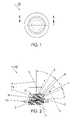
- FIG. 1is a top plan view of one embodiment of the invention in which a section line B-B is defined. This embodiment is radially symmetric.
- FIG. 2is the side cross sectional view depicted in FIG. 1 through section lines ‘B-B’.
- FIG. 3is a polar candela plot of the embodiment of the invention described in FIGS. 1 and 2 .
- the zero directionis the centerline of the device.
- FIG. 4is a side view of the embodiment of the invention described in FIGS. 1-3 showing a sample of rays traced from the source of the LED emitter through the al portion of the device.
- FIG. 5is a top view of another embodiment where the device is not radially symmetric. This view illustrates an embodiment which has two horizontally opposed lobes of the ‘blob’ lens.
- FIG. 6is an isometric view of the device of FIG. 5 more clearly describing its nonradially symmetric shape.
- FIG. 7is a side plan view of the device of FIG. 5 as seen parallel to section line D-D showing the reversal or undercut in the outline of the lens.
- FIG. 8is a side plan view that is rotated 90 degrees from the side view of FIG. 7 .
- FIG. 9is a cross-sectional view through section line ‘D-D’ of the device described in FIG. 5 . This cross-section shows the LED in addition to the lens.
- FIG. 10is the two dimensional iso-footcandle plot of the device of FIGS. 5-9 . This diagram illustrates the nonradially symmetric output of the device.
- FIG. 11is the iso-candela plot of the device of FIGS. 5-9 showing multiple plots of the device in different planes.
- FIG. 12is a side view of a ray tracing of the device of FIGS. 5-9 showing the rays traced from the LED emitter through the lens.
- FIG. 13is a side view of the same ray tracing shown in FIG. 12 , from a view azimuthally rotated 90 degrees from the view of FIG. 12 .
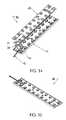
- FIG. 14is an exploded perspective view of a light module comprised of multiple devices of a preferred embodiment of the invention.
- FIG. 15is a perspective view of the assembled device of FIG. 14 , a flat modular light bar.
- FIG. 16is a perspective view of another preferred embodiment of the invention in which the device is asymmetric and creates a light pattern that is offset from a centerline of the LED.
- FIG. 17is a top plan view of the device of FIG. 16 .
- FIG. 18is a cross sectional side view of the device of FIGS. 16 and 17 as seen through section lines E-E of FIG. 17 .
- FIG. 19is a side plan view of the device of FIGS. 17-18 .
- FIG. 20is a side plan view of the device of FIGS. 17-19 as seen from a plane orthogonal to that seen in FIG. 19 .
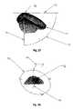
- FIG. 21is a perspective view of another embodiment of the invention using a complexly shaped prism. This embodiment is for streetlight and similar applications. It is azimuthally asymmetric and is oriented in the figure to show the ‘curb’ side of the streetlight or that side to which less light is directed.
- FIG. 22is a rotated perspective view of the device depicted in FIG. 21 showing the ‘street’ side of the device or that side of the device to which more light is directed.
- FIG. 23is a ‘bottom’ view of the device of FIGS. 21 and 22 showing the ‘street’ side on the right of the view and the curb side on the left of the view.
- FIG. 24is a side plan view of the embodiment of the invention described in FIGS. 21-23 showing in phantom outline the LED on which the lens of the device is mounted.
- FIG. 25is a rotated side plan view of the device of FIGS. 21-24 orthogonal to the view of FIG. 24 .
- FIG. 26is a rotated side plan view of the device of FIGS. 21-25 orthogonal to the view of FIG. 25 .
- FIG. 27is a side view of a three dimensional iso-candela mapped plot of the output of a device of FIGS. 21-26 , clearly showing the azimuthally asymmetric output of the device.
- the ‘street’ side of the beamis depicted to the right in the drawing and the curb side to the left.
- the plotillustrates that the invention can create a beam profile that generates the full-cutoff beam type required by IES standards for roadway and outdoor lighting.
- FIG. 28is a rotated perspective view of the iso-candela map of FIG. 27 showing the output of the device as seen from the ‘curb’ side and from above the device. It shows the bias of the beam toward the street and down the curb line.
- FIG. 29is a two dimensional iso-foot-candle plot of the light beam projected onto the ‘street’ from a device of the invention. This shows the non-radially symmetric output of a device of FIGS. 21-26 .
- the designerhas the freedom to control the shape of the lens to alter the output to match the requirements of the lighting task.
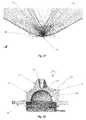
- FIG. 30is a cross-sectional view of a device of FIGS. 21-26 overlaid on a sample ray trace of the energy radiating from the LED emitter.
- the view of FIG. 30is the mirror image of the view of FIG. 25 . This view is upside down with the ‘street’ side facing to the left and above and shows refraction and reflection of various surfaces of the lens.
- FIG. 31is a cross-sectional view of a device of FIGS. 21-26 overlaid on a sample ray trace of the energy radiating from the LED emitter. This is a view similar to the view of FIG. 24 .
- FIG. 31is a cross-sectional view of the curb side of the device.
- FIG. 32is the cross-sectional view of the device of FIGS. 21-26 as seen through section lines F-F of FIG. 23 . This view illustrates the assembly of the device of FIGS. 21-26 with the LED.
- FIG. 33is a block diagram showing the steps of a method where a transfer function is employed.
- the illustrated embodiment of the inventionuses light emitting diodes (LED), or other light sources, in a device that directs the energy from the LED into a smooth, broad beam.
- a broad beamcan best be described as a beam which provides an illumination pattern on the surface intended to be illuminated, (e.g. the street, sidewalk, wall, etc.) that has a 50 percent maximum foot-candle measurement at an angle greater than 15 degrees from the centerline of the illumination pattern. This is referred to in the lighting field as the half-maximum point.
- a light source with a 15 degree half maximum measurementis also described as a 30 degree FWHM ( F ull W idth, H alf M aximum) light source.
- the preferred embodiment of the inventionhas a transparent ‘blob-like’ or complexly shaped lens, most likely of plastic or glass, that optically modifies light from the LED to generate the high angle intensity required for the wide beam angles without adding much if any additional reflective or refractive surface losses, other than what the LED packaging causes itself.
- the complex shape of the lensis determined by a transfer function that is disclosed below. It is the lack of additional surface losses that allow the preferred embodiment of the invention to be extremely efficient. However, it must be expressly understood that the scope of the invention contemplates designs that may depart from this efficiency standard to accommodate manufacturing artifacts or other compromises for the sake of economic production.
- the lensis ‘glued’ to the original LED protective cover with an index matching material so as to virtually eliminate the seam between the two.
- the lensis integrally manufactured into the protective dome or cover of the LED package.
- the ‘blob’ zoneis a small concentrating lens zone that is formed along the desired primary director of the device.
- This blob zone of the lenscollects the light rays emitted by the LED and sends them along a predetermined direction, i.e. the primary director, dependent on the beam angle desired by the optical designer.
- the lenswill be first considered to be a surface of revolution with a centerline or axis aligned with the centerline of the LED light pattern.
- This azimuthal symmetryis broken.
- the nearby surrounding surface of the lens to the blob zonealso collects light from the LED emitter and refracts it toward the preferential direction.
- the shape of the central forward cross-section of the lensgently apportions the energy in the segment from the directed blob zone to the centerline.
- the interior cross-sectional surface of the lens that is struck by the peripheral energy of the LED emitteris in a preferred embodiment undercut to either refract the light rays toward the preferential direction and/or internally reflect the light rays through the forward surface of the lens.
- the undercut surface of the lensis characterized by a smaller outer diameter defined from the centerline of the lens at the base of the lens than the outer diameter of the lens in the blob zone. In other words, the surface of the lens falls away or narrows at some point as the base of the lens is approached.
- an undercut surfacecould not be made in a single-piece mold, but would require a multiple piece mold for release.
- almost all the energy of the LEDis directed into the radiated beam without losses in excess of those generated by the LED without the invention deployed. Again, this is not to be understood as a limitation of the invention, which may include embodiments where greater losses than the native LED losses are permitted for various economic or manufacturing conveniences.
- One of the preferred embodiments of the inventiongenerates a beam that has a differential of angles, and therefore intensities, in its two primary axes.
- the ‘blob’ cross-section of the lensvaries as a function of the azimuthal angle about the centerline axis.
- This embodimentis intended for use in street lights and walkway lights or any use where there is a requirement for an asymmetrical or anamorphic beam.
- the iso-candela map of such a luminaireis nonuniform about its axes. Although it would be unusual, it is nevertheless contemplated within the scope of the invention that there could be more than two lobes along the opposing axes, such as a three, four or even more ‘blob’ axes.
- the preferred embodiment of the inventionthat a plurality of devices would be utilized in an array. It is expected that such an array might also be devised with two or more different ‘blob’ optical configurations to enhance the overall beam pattern.
- the arrayis disposed in a flat or planar arrangement as a module that can be readily scaled in size.
- the deviceis generally described as being used in the field of general lighting illumination, but it could be used in niche markets in the field of lighting and illumination as well.
- Uses of the inventioninclude, but are not limited to, street lighting, parking structure lighting, pathway lighting or any indoor or outdoor venues where a broad beam of light is desired, and is either azimuthally symmetric or biased in one or more axial directions.
- the illustrated embodimentcan also be used to advantage in mobile lighting in vehicles, aircraft, trains, vessels and the like. The number and variety of applications in which use can be made are too numerous to even attempt to list.
- a beamis generated that is offset in one or more axes from the projected centerline of the device.
- the resultant beamcan be used, for example, to generate a Type III roadway lighting luminaire which requires a beam pattern that has its primary director to be offset from its nadir.
- the lensappears to be a freeform shape with cross-sections that that may have tilted lobes and surfaces that cause individual rays of the beam to refract in a skewed manner.
- the embodimentalso includes additional surface shapes, like a complex prism, that add further control to the composition of the composite beam. It is also anticipated that facets, Fresnel type flattening of surface shapes in the form of complex prism, diffusing techniques or other surface enhancements may be added to lens to obtain a certain effect within the beam.
- beamis not often associated with highly divergent illumination devices, but it is used in this specification to describe the collectively formed output of the device, and is not necessarily limited a narrow beam of light.
- FIG. 1is an orthogonal top plan view of the device, generally denoted by reference numeral 10 .
- FIG. 2shows the device 10 in a cross-sectional view in position on LED 1 , which is a conventional packaged LED.
- LED emitter 2is positioned on the axis of the device 10 and in the embodiment shown the emitter 2 is centered in a hemispherical cavity (not shown) defined in a transparent, hemispherical protective dome 19 of the device 10 .
- zone Arepresents surface 5 of the lens 21 into which the forward solid angle of energy emitted from LED emitter 2 is collected, represented by rays 11 and 12 .
- Ray 11is transmitted within the lens 21 from emitter 2 to the surface of lens 21 and ray 12 is the refracted into zone A through the surface of the lens 21 .
- Zone Brepresents the surface 4 of the lens 21 referred to as the ‘blob’ zone. This surface 4 is situated on either side of the intended main director 6 at the approximate angle of the beam's highest desired intensity.
- Zone Crepresents the undercut surface 3 which collects the remaining peripheral forward solid angle of energy from the LED emitter 2 as represented by rays 7 , 8 and 9 . Ray 7 is transmitted from emitter 2 to the surface 3 within lens 21 , is totally internally reflected as ray 8 and then is refracted by surface 5 as ray 9 . However, it must be understood that some or, if desired, most of the rays from emitter 2 incident on surface 3 will not be internally reflected, but intentionally refracted through surface 3 as peripheral rays.
- Optional flange 13can be of most any desirable shape and is utilized for sealing the device 10 and/or any proximate portion of a light module manufactured with the device as described below.
- the shape of flange 13may be configured to provide for indexing or azimuthal alignment to a fixture in which device 10 of FIGS. 1-4 or particularly device 20 of FIGS. 5-9 , whose radiation pattern is not azimuthally symmetric, is set or may provide a snap fit connection of device 10 into the fixture.
- surface 3 of the depicted embodiment of the invention 10can be designed to be either totally internally reflective (TIR) or refractive or both.
- Surfaces 4 and 5are intended to be primarily refractive.
- the method used to design the embodiment shownis to first select the primary director angle 6 for the highest intensity, shown in the polar graph of FIG. 3 as point 14 . It has been determined by empirical testing that if this director angle passes much beyond 60-62 degrees from the centerline, the resultant effect is to limit the ability of the device 10 to perform its primary task of providing a significant increase in the iso-candela plot of the off-axis energy as shown by point 14 of FIG. 3 and still achieve the goal of a smooth, useful beam. In the embodiment of FIG. 3 the maximum intensity occurs at about 52 degrees off axis.
- surface 4 of zone Bis defined as an arc which has its center disposed along the director 6 .
- the radius and the start and end angles of the arc defining surface 4are variables defined by iteration with the surface definitions of zones A and C.
- the surface 5is defined as a concave refractive surface intended in this embodiment to ‘spread’ the central solid angle of energy from the LED emitter 2 outward from the centerline.
- the merge point of surfaces 4 and 5 between zones A and Bis found by construction. In the embodiment shown, surfaces 4 and 5 are tangent to each other or smooth at the merge point. However, it is not a requirement of the invention that they be tangent.
- Surface 3 of zone Cis also defined in the embodiment shown as a surface generated by a tangent arc.
- the resultant beamcan be defined in total and will include almost all the energy emitted by LED emitter 2 . Measurements have shown that the resultant beam can include virtually the same number of lumens into an integrating sphere as the original LED does without lens 21 .
- Manipulation of the shapes of surfaces 3 , 4 and 5 of FIG. 2can be performed until the desired intensity ratios and angles of intensity are represented in a polar candela distribution plot of the design as depicted in FIG. 3 .
- surfaces 3 , 4 and 5could be represented by any number of differently shaped surfaces including one or more which are point wise defined, rather than geometric shapes in zones as depicted.
- shape of the profiles of surfaces 3 , 4 and 5could be derived by computer calculation as a function of the desired beam profile as defined in the polar candela distribution plot and the resultant surface(s) profile used as the surfaces of revolution in the case of a radially symmetric design.
- FIG. 4shows the result of a ray trace of the device 10 of FIGS. 1 and 2 .
- the rayshave been reduced to a small percentage of those traced to better show the effects of rays as they react to the surfaces 3 , 4 and 5 of each of the above described zones A, B and C.
- light rays from a ray traceonly simulate the effects of light energy from a light source.
- FIG. 5shows a three quarter perspective view of another preferred embodiment 20 of the invention whereby the resultant beam energy pattern is not azimuthally symmetric.
- Circular lip 18 of FIGS. 6-9represents a sealing feature that optionally allows the device 20 to be sealed when built into a light fixture or an array.
- the cross sectional view of FIG. 9is taken through section line D-D of FIG. 5 .
- the top plan view of the device 20is represented by the diametrically opposing ‘blob’ segments 14 and the diametrically opposing smoother side segments 15 azimuthally orthogonal to the blob segments 14 . It is easier to understand these profiles by looking at FIGS. 7 and 8 , which show the profiles of the segments 14 and 15 from both horizontal and vertical directions respectively, and FIG.
- FIG. 6which shows the device 20 in a rotated oblique view that shows its elongated profile.
- FIG. 7shows that the illustrated profile in this view is similar to the device 20 shown in FIGS. 1 and 2 .
- the ‘blob’ shape in the embodiment of FIG. 7is defined by multiple cross-sections of segments 14 and 15 rotated about the centerline 23 in which the surface of lens 2 lis lofted between cross-sections of segments 14 and 15 much like the lofting of a boat hull.
- the ‘blob’ or lobed segment 14is defined as well as the smoothing of surface segments between the diametrically opposing ‘blobs’ or lobes 14 .
- Loftingis a drafting technique (sometimes using mathematical tables) whereby curved lines are drawn on a plan between cross-sectional planes. The technique can be as simple as bending a flexible object such as a long cane so that it passes over three non-linear points and scribing the resultant curved line, or plotting the line using computers or mathematical tables. Lofting has been traditionally used in boat building for centuries, when it is used to draw and cut pieces for hulls and keels, which are usually curved, often in three dimensions.
- the ‘blob’ or lobe segment 14is defined similarly to the device 10 shown in FIG. 2 .
- the zones A, B and C of the embodiment of FIG. 9are similar as are the rays 25 , 26 and rays 32 - 34 are similar to analogous rays 12 , 11 , 7 , 8 and 9 respectively of FIG. 2 .
- the undercut surface 31 as shownis flat, but it could be any shape or angle that provides the desired result.
- the undercut surface 31 of FIGS. 5-9 or surface 3 of FIGS. 1-4differs from undercut surfaces which can be found in conventional total internal reflectors (TIR) in that the surfaces of the conventional TIR are located in what would be termed the far field of the LED and not its near field.
- TIRtotal internal reflectors
- surfaces 3 and 31are near field surfaces in that they are optically closely coupled to the LED source and ideally have no air gap or at least no substantial air gap between the LED and the surface 3 or 31 .
- the undercut surfacesare generally used as reflective surfaces and to the extent that there are refracted rays emitted through such surfaces, the rays are lost to the useful beam or what is the intended beam of light.
- the undercut surfaces 3 and 31optically contribute to the intend beam to a material degree, both in the reflected as well as the refracted rays incident on them.
- LED emitter 29is disposed approximately at the center of the hemispherically shaped surface 17 of FIGS. 7 and 8 , which matches the shape of dome 19 .
- LED package 28 and the device 20are optionally bonded with an index matching material at surface 17 of lens 21 and the dome 19 of the LED package 28 .
- the device 20be incorporated in the production of the LED package 28 in an alternate embodiment whereby the manufacturer of the LED does not bond a separate lens 21 to the LED; however, the lens 21 of device 20 is the protective dome of the LED package 28 itself. In either case, the resultant devices 20 shall be very similar optically.
- the mechanical features at the base of the deviceare optional and may be utilized or not.
- FIG. 10shows a two dimensional iso-foot-candle plot of the output of the device 20 shown in FIGS. 5-9 . It shows the anamorphic shape of the output beam which is nearly two times the length/width ratio of a azimuthally symmetric beam of the embodiment of FIGS. 1-4 .
- FIG. 11shows the polar iso-candela plot with overlaid angles of candela data.
- the plot 35is the intensity distribution as seen in the horizontal plane of FIG. 7
- plot 38is the intensity distribution as seen in the azimuthally orthogonal plane of FIG. 8
- plot 36is the intensity distribution as seen in a plane at 45 degrees or half way between the views of FIG. 7 and FIG. 8 .
- the maximum of intensity distribution patterndecreases as the view rotates from the plane of FIG. 7 to the plane of FIG. 8 as shown in the plots 35 , 36 and 38 and the decreases in angle or rotates upwardly from about 52 degrees to about 40 degrees off axis.
- FIGS. 12 and 13are ray trace plots of the device of FIGS. 5-9 . These plots show graphically the path of energy from the LED emitter 29 in the planes corresponding to FIGS. 7 and 8 respectively. As in the device 10 of FIGS. 1 and 2 , the surface of zone C of FIG. 9 is both refractive and totally internally reflective in this embodiment of the invention.
- FIGS. 14 and 15illustrate a further embodiment of the invention which incorporates a plurality of devices 21 or 20 of the invention by which a light module 40 is provided.
- This light module 40can be the basis of a flat luminaire that is used for street lighting, pathway lighting, parking structure lighting, decorative lighting and any other type of spread beam application.
- Light module 40is shown as a rectangular flat bar, but can assume any two dimensional planar shape, such as square, circular, hexagonal, triangular or an arbitrary free form shape. Inasmuch as light module 40 is flat it can be mounted in its corresponding fixture parallel to the two dimensional plane that it is intended to illuminate, such as the street, walk or floor.
- the light module 40is a very simple and low cost means to provide LED lighting to luminaire manufacturers where the light module 40 can be treated in the designs of as a single ‘light bulb’. With the addition of heat sinking and power incorporated on or into module 40 , the light module 40 can be easily incorporated into existing luminaires or integrated into new designs.
- FIG. 14shows a disassembled conventional LED package 28 and the ‘blob’ lens 21 which is disposed onto LED package 28 .
- FIGS. 14 and 15further show a flat heat dissipating carrier 41 to which the LEDs 28 are attached.
- the flat carrier 41which is typically made of metal, such as a heat conductive aluminum alloy, could provide just enough heat dissipation and conduction to allow proper cooling of the LED with the addition of a properly designed heat sink or other heat dissipating means, or the carrier 41 could be the entire heat sink or other heat dissipating means itself.
- a printed circuit board 46is shown as a convenient means to provide power to the LEDs 28 , however it could be eliminated and the LEDs could be wired to each other directly. Additional means of conveying power to the LEDs 28 are contemplated by the invention.
- the wires 42 shownare just one means of providing power to the light module 40 . Connectors, sockets, plugs, direct wiring and other means are equivalent substitutes.
- the light moduleis covered by a molded component 43 or a co-molded cover 43 or any other means of providing a seal, such as a potting compound, or optionally no seal at all.
- An optional potting compound, which is forced or disposed between cover 43 and carrier 41is just one means of providing sealing for the light module 40 , rendering it in such an embodiment as waterproof or submersible.
- the assembled module 40 as shown in FIG. 15can include hold down features, alignment features as well as other conventional features desired for implementation into a luminaire.
- FIGS. 16-20depict another preferred embodiment of the invention wherein the resultant ‘beam’ of light energy is directed in a skewed fashion with respect to the centerline of the device 20 .
- the beamcan be defined as having ‘lobes’ of intensity that are not coincident with the primary axes of the device 20 .
- the device shown in FIG. 16is similar to FIG. 6 in all respects with two exceptions, first there a complexly shaped prism 50 is provided on the top of lens 21 and the second is described as follows.
- lobes 14are similar to lobes 14 in FIG. 5 while the flattened sides 15 are slightly radially extended with a central bulge.
- Prism 50is complexly shaped to provide a means for directing light in zone A into a direction which is more dramatically skewed relative to centerline 23 .
- the top surface 5is angled off axis to further skew the light in the same general direction to which prism 50 is directed.
- Prism 50has at least four separately definable surfaces, which in plan view vaguely resemble the top plan surface of a toilet and water closet. The surfaces are empirically determined by trial and error from the desired skewed polar candela plot and are strongly dependent thereon. Therefore, the surfaces of prism 50 will not be described in greater detail other than to specify that the net effect is to redirect the light incident on prism 50 from within lens 21 toward one side of the light pattern skewed relative to the centerline 23 .
- FIG. 21is a perspective view of the device, generally denoted by reference numeral 10 .
- FIG. 22shows the device 10 in another perspective view.
- Optional flange 30is shown to have a keyed shape that allow the lens 21 to be rotationally indexed in an assembly or fixture (not shown).
- the flange 30may also be utilized to seal the LED housed in lens 21 into an assembly by a mating part (not shown) that interfaces or interlocks with the flange 30 .
- Optional seal 18is shown as a part of the flange 30 and may be incorporated into it by many different means.
- Surfaces 57 and 58 of lens 21are utilized to direct the energy from the LED's peripheral beam, which is defined as the energy radiating in the solid angular zone from a horizontal plane parallel to the plane of the LED emitter to approximately 45 degrees from the perpendicular centerline of the LED emitter, while surfaces 51 , 52 and 59 direct the energy in the solid angular zone from the LED's centerline to approximately 45 degrees from the centerline, the primary LED director.
- One very important element of the inventionis the zone of the lens 21 depicted by surfaces 51 and 70 .
- the surfaces 51 and 70form the principle parts of a complex prism on the surface of lens 21 , which is called a “Pope's hat”.
- the solid angle zone of the light served by surfaces 51 and 70takes the energy from the primary directed beam of the LED's ‘curb’ side and redirects it toward the ‘street’ side.
- Optional surface 53is a blended contour between surfaces 52 and 58 .
- Surface 57is mirrored across intersection 54 in FIG. 23 and is lofted in the embodiment shown to redirect the centerline energy of the LED down the ‘curb’ direction and across the centerline.
- Surface 57allows for very high efficiency for the lens 21 in both the street and the curb side of its light pattern.
- surface 52is depicted as an azimuthally symmetric surfaced defined through an azimuthal angle of about 185 degrees. While this is desirable for some applications it is well within the scope of the invention that surface 52 and its adjacent surfaces may be azimuthally asymmetric.
- Surface 59is an optional feature to redirect the centerline energy of the LED. Surface 59 can take of many different forms to allow the designer freedom to shape the beam. In the embodiment of FIGS. 21-26 the shape of surface 59 is utilized to allow for a continuation of the light spreading effect of surface 52 , but constrained to keep the thickness of the device 10 within manufacturing capabilities.
- interface 62 between dome 19 and lens 21is utilized if the lens 21 is a molded optic separate from the LED. If the lens 21 of the device 10 were molded directly on or assembled by the manufacturer on the LED emitter, interface 62 does not exist. Interface 62 is comprised of the two mating surfaces of the LED dome 19 and the inside of the lens 21 . It would be most desirable if the interface were bonded with an index matching cement or a thixtropic index matching material were retained in interface 62 . Using an index matching material, optical measurements have shown that the resultant beam from the assembled device 10 can include virtually the same number of lumens into an integrating sphere as the original LED does without lens 21 .
- FIG. 27The nadir 74 of the device 10 is shown in FIG. 27 as well as is the horizon 72 and the ‘street’ side angle marker 73 .
- the rays 70 of maximum candela of the resultant beamare illustrated in the rightmost portion of the drawing.
- FIG. 28is a rotated three dimensional view of the same candela map as FIG. 27 and shows the plot as it would be seen from the curb side of the pattern at the bottom portion of the view.
- the ability of the various surfaces of lens 21 described in FIGS. 21-26 to throw or transfer energy from one side of the Lambertian output of the conventional LED to one side of the illumination patternis graphically illustrated. Note also that all the rays are directed in FIG. 27 in a downward direction with little if any energy in the direction of horizon 72 or upward. Sky rays are virtually eliminated.
- lens 21can be performed until the desired intensity ratios and angles of candela are represented in a ray trace of the design as depicted in FIGS. 27 and 28 or modifications thereof according to the teachings of the invention. It must be understood that the lens surfaces could be represented by any number of separate surfaces including one or more which are defined by a point wise transfer function rather than geometric segmental shapes.
- the shape of the profiles of the lens surfacescould be derived by a computer calculation derived from a predetermined beam profile and the resultant lens surface(s) profile(s) then used as the cross-section(s) of various portions of the lens 21 according to the teachings of the invention.
- FIG. 29is a plot of the two dimensional distribution of energy as it strikes the surface of the ‘street’ below the device 10 .
- This plotgenerally would be described with iso-intensity contour lines in units of energy such as foot-candle or lux.
- the device 10is centered in the drawing of FIG. 29 with the ‘street’ side to the right of center and the ‘curb’ side to the left of center.
- the plotis symmetry about a horizontal line running from the curb to the street with identical intensity patterns in the top and bottom portions of the drawing.
- FIG. 30is a ray tracing of the device 10 of FIGS. 21-26 as seen in a side view reversed from that shown in FIG. 25 .
- the rayshave been reduced to a small percentage of those which could be traced to better show the effects of rays as they are redirected from the Lambertian pattern of the LED housed within lens 21 by the surfaces of the lens 21 .
- Rays 82correspond to the rays directed by surface 52 .
- Rays 83are directed by undercut surface 58 .
- FIGS. 24-26show a small undercut portion of surface 58 which extends partially around the base of lens 21 .
- rays 80 which are redirected from surface 51show that surface 51 is acting as a TIR reflector of the beam energy from the LED on the ‘curb’ side to transfer energy to the ‘street’ side.
- Rays 81are refracted LED energy in a direction away from the centerline of the LED beam pattern. Stray rays 81 show losses which arise in the lens 21 as a result of manipulating the beam pattern.
- the emitter 29 in the LEDis assumed above to be a Lambertian emitter.
- the concept of using a ‘floating’ reflective surface on the ‘curb’ side of lens 21 to reflect light to the ‘street’ side of a lens 21is expressly included within the scope of the invention even when using HID or other light sources with different emission patterns. Any kind of light source now known or later devised may be employed in the disclosed combination of the invention with appropriate modifications made according to the teachings of the invention. Wherever in this description the terms associated with streetlights are used, such as ‘street’ side or ‘curb’ side, they could be substituted with other terms that describe offset beam patterns in general.
- FIG. 31is another cross-section view of a ray tracing of the embodiment of FIGS. 21-26 as seen in a frontal view of FIG. 26 .
- the rays radiating from the side plan view of FIG. 26are refracted toward the street surface.
- Rays 91represents the energy from the LED in the primary zone refracted outward by the surface 52 of FIGS. 21-26 . Again few if any rays directed toward the horizon are present.
- FIG. 32is a solid cross-sectional view of device 10 as seen through line F-F of FIG. 23 .
- FIG. 32shows an LED with emitter 29 with lens 21 optionally glued in place with the interface 62 or seam bonded with an index matching cement.
- the optional flange 30can be seen as a sealing feature to mate with additional components of an assembly (not shown).
- Surface 57represents the transition between the ‘street’ side profiles and the ‘curb’ side profiles of lens 21 that mainly refract light toward the street from the peripheral Lambertian beam of the LED. More particularly, surface 57 is divided into two subsurfaces by a centerline 54 in the embodiment of FIGS. 21 , 23 and 24 , which subsurfaces spread the light in the beam outward from the centerline 54 in larger angles.
- centerline 54were perpendicularly oriented to the curb in a street light installation, the subsurfaces would spread the beam transmitted through surface 57 in directions more parallel to the curb and away from the centerline 54 .
- Surface 51primarily reflects energy from the LED primary light direction from the ‘curb’ side toward the ‘street’ side.
- FIG. 33summarizes an overall conceptualization of the methodology of the invention.
- the problem solved by the inventionis defined by two boundary conditions, namely the light pattern of the light source which is chosen at step 100 and the two dimensional iso-foot candle plot which is to be projected onto the surface which is intended to be illuminated in step 106 .
- the problem of providing a wide beam street light patternis assumed for the boundary condition of step 106 and the Lambertian pattern of an LED is assumed in the boundary condition 100 .
- the same problem defined by different characterizations of the boundary conditions of steps 100 and 106are expressly included within the scope of the claimed invention.
- boundary condition 100need not assume the Lambertian pattern of an LED, but may take as the boundary condition the three dimensional energy distribution pattern of a high intensity discharge (HID) lamp.
- Light sources which do not assume the Lambertian pattern of an LED, like a high intensity discharge lamp,are defined for the purposes of this specification as non-Lambertian light sources.
- the problemthen becomes recast as how to get the shape of a lens or optic 21 which provides the needed transfer function between the two boundary conditions of steps 100 and 106 , namely the three dimensional energy distribution pattern of the light source to the projected two dimensional illumination pattern for the target surface.
- the problemis nontrivial.
- the solution for an asymmetric broad or spread beamhas been disclosed in connection with FIGS. 1-32 above and the related specification.
- the three dimensional lens shapeis determined at step 102 as shown in FIGS. 1-9 , 16 - 20 and 21 - 26
- the three dimensional candela plot as shown in FIGS. 11 , 27 and 28 and as suggested by the ray tracings of FIGS. 12 , 13 , 30 and 31can be mathematically derived using conventional optical computer aided design programs, such Photopia® sold by Lighting Technologies of Denver, Colo., assuming the three dimensional energy distribution of the light source, e.g. a Lambertian distribution in the case of an LED.
- the two dimensional iso-foot candle plots of FIGS. 10 and 29can be mathematically derived using conventional optical computer aided design programs. The results obtained are then compared to the boundary condition of step 106 . To the extent that the boundary condition of step 106 is not satisfied, the optical designer through trial and error can modify the three dimensional shape of lens 21 in step 102 and again repeat steps 104 and 106 in a reiterative process until the desired conformity with the target two dimensional iso-foot candle plot is obtained.
- the inventionalso includes the methodology where the needed lens shape is rendered mathematically through an analytical process or numerically through a numerical reiterative estimation process with the boundary conditions of steps 100 and 106 as numerical inputs consistent with the teachings of the invention.
- a plurality of such devicescan then be combined into an array of devices.
- Each device in the arrayhas the same three dimensional energy distribution pattern that results in the same intended two dimensional illumination pattern on the target surface or street.
- their respective illumination patternsare substantially linearly superimposed on each other to provide the same illumination pattern on the target surface or street as produced by a single device, but with the increased intensity of the plurality of devices in the array.
- the arrayscan be manufactured in a modular fashion, so that a plurality of arrays combined together can still have a relatively small size compared to the distance to or the size of the illumination pattern on the target surface or street, that the illumination pattern of each array substantially overlays the same illumination pattern of all the other arrays in the collection.
- the intensity of the illumination pattern on the target surface from the collection of arrayscan be scaled without substantial modification of the illumination pattern by modular scaling of the arrays into larger or smaller collections.
Landscapes
- Engineering & Computer Science (AREA)
- Physics & Mathematics (AREA)
- General Engineering & Computer Science (AREA)
- Optics & Photonics (AREA)
- General Physics & Mathematics (AREA)
- Microelectronics & Electronic Packaging (AREA)
- Non-Portable Lighting Devices Or Systems Thereof (AREA)
- Led Device Packages (AREA)
- Led Devices (AREA)
Abstract
Description
Claims (98)
Priority Applications (13)
| Application Number | Priority Date | Filing Date | Title |
|---|---|---|---|
| US11/711,218US7674018B2 (en) | 2006-02-27 | 2007-02-26 | LED device for wide beam generation |
| US12/690,821US7993036B2 (en) | 2006-02-27 | 2010-01-20 | LED device for wide beam generation |
| US12/690,751US8434912B2 (en) | 2006-02-27 | 2010-01-20 | LED device for wide beam generation |
| US12/690,794US7942559B2 (en) | 2006-02-27 | 2010-01-20 | LED device for wide beam generation |
| US13/109,582US20110216537A1 (en) | 2006-02-27 | 2011-05-17 | LED Device for Wide Beam Generation |
| US13/109,609US8210722B2 (en) | 2006-02-27 | 2011-05-17 | LED device for wide beam generation |
| US13/422,871US8511864B2 (en) | 2006-02-27 | 2012-03-16 | LED device for wide beam generation |
| US13/540,477US8414161B2 (en) | 2006-02-27 | 2012-07-02 | LED device for wide beam generation |
| US13/858,713US8905597B2 (en) | 2006-02-27 | 2013-04-08 | LED device for wide beam generation |
| US13/970,197US9388949B2 (en) | 2006-02-27 | 2013-08-19 | LED device for wide beam generation |
| US14/563,081US9297520B2 (en) | 2006-02-27 | 2014-12-08 | LED device for wide beam generation |
| US15/083,076US10174908B2 (en) | 2006-02-27 | 2016-03-28 | LED device for wide beam generation |
| US16/241,852US20190137074A1 (en) | 2006-02-27 | 2019-01-07 | LED Device for Wide Beam Generation |
Applications Claiming Priority (4)
| Application Number | Priority Date | Filing Date | Title |
|---|---|---|---|
| US77731006P | 2006-02-27 | 2006-02-27 | |
| US83803506P | 2006-08-15 | 2006-08-15 | |
| US86178906P | 2006-11-29 | 2006-11-29 | |
| US11/711,218US7674018B2 (en) | 2006-02-27 | 2007-02-26 | LED device for wide beam generation |
Related Child Applications (4)
| Application Number | Title | Priority Date | Filing Date |
|---|---|---|---|
| US12/690,751DivisionUS8434912B2 (en) | 2006-02-27 | 2010-01-20 | LED device for wide beam generation |
| US12/690,821ContinuationUS7993036B2 (en) | 2006-02-27 | 2010-01-20 | LED device for wide beam generation |
| US12/690,821DivisionUS7993036B2 (en) | 2006-02-27 | 2010-01-20 | LED device for wide beam generation |
| US12/690,794DivisionUS7942559B2 (en) | 2006-02-27 | 2010-01-20 | LED device for wide beam generation |
Publications (2)
| Publication Number | Publication Date |
|---|---|
| US20070201225A1 US20070201225A1 (en) | 2007-08-30 |
| US7674018B2true US7674018B2 (en) | 2010-03-09 |
Family
ID=38459646
Family Applications (10)
| Application Number | Title | Priority Date | Filing Date |
|---|---|---|---|
| US11/711,218ActiveUS7674018B2 (en) | 2006-02-27 | 2007-02-26 | LED device for wide beam generation |
| US12/690,794ActiveUS7942559B2 (en) | 2006-02-27 | 2010-01-20 | LED device for wide beam generation |
| US12/690,821ActiveUS7993036B2 (en) | 2006-02-27 | 2010-01-20 | LED device for wide beam generation |
| US13/109,582AbandonedUS20110216537A1 (en) | 2006-02-27 | 2011-05-17 | LED Device for Wide Beam Generation |
| US13/109,609ActiveUS8210722B2 (en) | 2006-02-27 | 2011-05-17 | LED device for wide beam generation |
| US13/540,477ActiveUS8414161B2 (en) | 2006-02-27 | 2012-07-02 | LED device for wide beam generation |
| US13/858,713Active2027-03-21US8905597B2 (en) | 2006-02-27 | 2013-04-08 | LED device for wide beam generation |
| US14/563,081ActiveUS9297520B2 (en) | 2006-02-27 | 2014-12-08 | LED device for wide beam generation |
| US15/083,076Active2027-04-14US10174908B2 (en) | 2006-02-27 | 2016-03-28 | LED device for wide beam generation |
| US16/241,852AbandonedUS20190137074A1 (en) | 2006-02-27 | 2019-01-07 | LED Device for Wide Beam Generation |
Family Applications After (9)
| Application Number | Title | Priority Date | Filing Date |
|---|---|---|---|
| US12/690,794ActiveUS7942559B2 (en) | 2006-02-27 | 2010-01-20 | LED device for wide beam generation |
| US12/690,821ActiveUS7993036B2 (en) | 2006-02-27 | 2010-01-20 | LED device for wide beam generation |
| US13/109,582AbandonedUS20110216537A1 (en) | 2006-02-27 | 2011-05-17 | LED Device for Wide Beam Generation |
| US13/109,609ActiveUS8210722B2 (en) | 2006-02-27 | 2011-05-17 | LED device for wide beam generation |
| US13/540,477ActiveUS8414161B2 (en) | 2006-02-27 | 2012-07-02 | LED device for wide beam generation |
| US13/858,713Active2027-03-21US8905597B2 (en) | 2006-02-27 | 2013-04-08 | LED device for wide beam generation |
| US14/563,081ActiveUS9297520B2 (en) | 2006-02-27 | 2014-12-08 | LED device for wide beam generation |
| US15/083,076Active2027-04-14US10174908B2 (en) | 2006-02-27 | 2016-03-28 | LED device for wide beam generation |
| US16/241,852AbandonedUS20190137074A1 (en) | 2006-02-27 | 2019-01-07 | LED Device for Wide Beam Generation |
Country Status (8)
| Country | Link |
|---|---|
| US (10) | US7674018B2 (en) |
| EP (5) | EP2383561A1 (en) |
| JP (1) | JP2009528556A (en) |
| KR (1) | KR101156272B1 (en) |
| CN (2) | CN104110609B (en) |
| AU (1) | AU2007221100B2 (en) |
| CA (1) | CA2641832C (en) |
| WO (1) | WO2007100837A2 (en) |
Cited By (117)
| Publication number | Priority date | Publication date | Assignee | Title |
|---|---|---|---|---|
| US20080198594A1 (en)* | 2006-12-19 | 2008-08-21 | Lee Sungkeun | Optical module |
| US20080303757A1 (en)* | 2007-06-06 | 2008-12-11 | Sony Corporation | Light emitting device, area light source apparatus and image display apparatus |
| US20090225551A1 (en)* | 2008-03-07 | 2009-09-10 | Industrial Technology Research Institute | Illumination apparatus |
| US20090225543A1 (en)* | 2008-03-05 | 2009-09-10 | Cree, Inc. | Optical system for batwing distribution |
| US20090268453A1 (en)* | 2008-04-24 | 2009-10-29 | King Luminarie Co., Inc. | LED baffle assembly |
| US20090284951A1 (en)* | 2006-06-30 | 2009-11-19 | Julius Muschaweck | Optoelectronic component and illumination device |
| US20090290360A1 (en)* | 2008-05-23 | 2009-11-26 | Ruud Lighting, Inc. | Lens with tir for off-axial light distribution |
| US20090310356A1 (en)* | 2008-06-13 | 2009-12-17 | Koninklijke Philips Electronics N.V. | Orientable lens for an led fixture |
| US20100073938A1 (en)* | 2008-09-19 | 2010-03-25 | Genius Electronic Optical Co., Ltd. | Two-side asymmetric light-shift illuminating lens body |
| US20100128489A1 (en)* | 2006-02-27 | 2010-05-27 | Illumination Management Solutions Inc. | Led device for wide beam generation |
| US20100135028A1 (en)* | 2007-08-09 | 2010-06-03 | Sharp Kabushiki Kaisha | Light emitting device and lighting device having the same |
| US20100134046A1 (en)* | 2008-12-03 | 2010-06-03 | Illumination Management Solutions, Inc. | Led replacement lamp and a method of replacing preexisting luminaires with led lighting assemblies |
| US20100172135A1 (en)* | 2006-02-27 | 2010-07-08 | Illumination Management Solutions Inc. | Led device for wide beam generation |
| US7766509B1 (en) | 2008-06-13 | 2010-08-03 | Lumec Inc. | Orientable lens for an LED fixture |
| US20100226130A1 (en)* | 2009-03-04 | 2010-09-09 | Unilumin Group Co., Ltd. | Led light module for street lamp and method of manufacturing same |
| US20100238669A1 (en)* | 2007-05-21 | 2010-09-23 | Illumination Management Solutions, Inc. | LED Device for Wide Beam Generation and Method of Making the Same |
| US20100265723A1 (en)* | 2009-04-21 | 2010-10-21 | Jian-Lin Zhou | Optical transformation device |
| US20100302786A1 (en)* | 2008-05-23 | 2010-12-02 | Ruud Lighting, Inc. | Lens with controlled backlight management |
| US20110051427A1 (en)* | 2009-09-03 | 2011-03-03 | Fu Zhun Precision Industry (Shen Zhen) Co., Ltd. | Led module |
| US20110068708A1 (en)* | 2009-09-23 | 2011-03-24 | Ecofit Lighting, LLC | LED Light Engine Apparatus |
| US20110080730A1 (en)* | 2008-05-20 | 2011-04-07 | Koninklijke Philips Electronics N.V. | Optical element for asymmetric light distribution |
| US20110122619A1 (en)* | 2008-07-15 | 2011-05-26 | Ruud Lighting, Inc. | Light-directing apparatus with protected reflector-shield and lighting fixture utilizing same |
| US20110157891A1 (en)* | 2009-11-25 | 2011-06-30 | Davis Matthew A | Systems, Methods, and Devices for Sealing LED Light Sources in a Light Module |
| US20110242807A1 (en)* | 2010-03-31 | 2011-10-06 | Aphos Lighting Llc | Light cover and illuminating apparatus applying the same |
| US8220958B2 (en) | 2007-04-05 | 2012-07-17 | Koninklijke Philips Electronics N.V. | Light-beam shaper |
| US8246212B2 (en) | 2009-01-30 | 2012-08-21 | Koninklijke Philips Electronics N.V. | LED optical assembly |
| USD673307S1 (en) | 2011-05-12 | 2012-12-25 | Cooper Technologies Company | Light bar |
| US8376583B2 (en) | 2010-05-17 | 2013-02-19 | Orion Energy Systems, Inc. | Lighting system with customized intensity and profile |
| US8388198B2 (en) | 2010-09-01 | 2013-03-05 | Illumination Management Solutions, Inc. | Device and apparatus for efficient collection and re-direction of emitted radiation |
| US20130120974A1 (en)* | 2011-11-10 | 2013-05-16 | Electrix, Inc. | Wall Wash Lighting Fixture |
| US8454205B2 (en) | 2008-08-14 | 2013-06-04 | Cooper Technologies Company | LED devices for offset wide beam generation |
| US20130322088A1 (en)* | 2012-06-05 | 2013-12-05 | Foshan Nationstar Optoelectronics Co., Ltd. | Large-Angle Lens and Large-Angle Emission LED Light Source Module |
| USD697664S1 (en) | 2012-05-07 | 2014-01-14 | Cree, Inc. | LED lens |
| US8628222B2 (en) | 2011-05-13 | 2014-01-14 | Lighting Science Group Corporation | Light directing apparatus |
| US8801221B2 (en) | 2012-01-06 | 2014-08-12 | Young Lighting Technology Inc. | Lens structure, light source device and light source module |
| US20140313742A1 (en)* | 2011-07-08 | 2014-10-23 | Zumtobel Lighting Gmbh | Light-influencing element for influencing the light emission of essentially point light sources and luminaire having a light-influencing element |
| USD718490S1 (en) | 2013-03-15 | 2014-11-25 | Cree, Inc. | LED lens |
| US20140355302A1 (en)* | 2013-03-15 | 2014-12-04 | Cree, Inc. | Outdoor and/or Enclosed Structure LED Luminaire for General Illumination Applications, Such as Parking Lots and Structures |
| US9052086B2 (en) | 2011-02-28 | 2015-06-09 | Cooper Technologies Company | Method and system for managing light from a light emitting diode |
| US20150184826A1 (en)* | 2013-12-26 | 2015-07-02 | Hon Hai Precision Industry Co., Ltd. | Light emitting device and backlight module employing same |
| US9080739B1 (en) | 2012-09-14 | 2015-07-14 | Cooper Technologies Company | System for producing a slender illumination pattern from a light emitting diode |
| US9140430B2 (en) | 2011-02-28 | 2015-09-22 | Cooper Technologies Company | Method and system for managing light from a light emitting diode |
| WO2015157327A1 (en)* | 2014-04-08 | 2015-10-15 | Cooper Technologies Company | Adjustable light module |
| US9200765B1 (en) | 2012-11-20 | 2015-12-01 | Cooper Technologies Company | Method and system for redirecting light emitted from a light emitting diode |
| US9255686B2 (en) | 2009-05-29 | 2016-02-09 | Cree, Inc. | Multi-lens LED-array optic system |
| US9291320B2 (en) | 2013-01-30 | 2016-03-22 | Cree, Inc. | Consolidated troffer |
| US9360172B2 (en) | 2011-07-19 | 2016-06-07 | Zumtobel Lighting Gmbh | Arrangement for emitting light |
| US9366799B2 (en) | 2013-03-15 | 2016-06-14 | Cree, Inc. | Optical waveguide bodies and luminaires utilizing same |
| US9366396B2 (en) | 2013-01-30 | 2016-06-14 | Cree, Inc. | Optical waveguide and lamp including same |
| US9374870B2 (en) | 2012-09-12 | 2016-06-21 | Sensity Systems Inc. | Networked lighting infrastructure for sensing applications |
| US9389367B2 (en) | 2013-01-30 | 2016-07-12 | Cree, Inc. | Optical waveguide and luminaire incorporating same |
| US9410674B2 (en) | 2014-08-18 | 2016-08-09 | Cree, Inc. | LED lens |
| US9423096B2 (en) | 2008-05-23 | 2016-08-23 | Cree, Inc. | LED lighting apparatus |
| US9442243B2 (en) | 2013-01-30 | 2016-09-13 | Cree, Inc. | Waveguide bodies including redirection features and methods of producing same |
| US9456293B2 (en) | 2013-03-26 | 2016-09-27 | Sensity Systems Inc. | Sensor nodes with multicast transmissions in lighting sensory network |
| US9457907B2 (en) | 2013-04-15 | 2016-10-04 | The Boeing Company | Direction controlled service apparatus |
| US9523480B2 (en) | 2014-04-05 | 2016-12-20 | Whelen Engineering Company, Inc. | LED illumination assembly with collimating optic |
| US9523479B2 (en) | 2014-01-03 | 2016-12-20 | Cree, Inc. | LED lens |
| US9541257B2 (en) | 2012-02-29 | 2017-01-10 | Cree, Inc. | Lens for primarily-elongate light distribution |
| US9541258B2 (en) | 2012-02-29 | 2017-01-10 | Cree, Inc. | Lens for wide lateral-angle distribution |
| US9565782B2 (en) | 2013-02-15 | 2017-02-07 | Ecosense Lighting Inc. | Field replaceable power supply cartridge |
| US9568665B2 (en) | 2015-03-03 | 2017-02-14 | Ecosense Lighting Inc. | Lighting systems including lens modules for selectable light distribution |
| US9582671B2 (en) | 2014-03-06 | 2017-02-28 | Sensity Systems Inc. | Security and data privacy for lighting sensory networks |
| USD782093S1 (en) | 2015-07-20 | 2017-03-21 | Ecosense Lighting Inc. | LED luminaire having a mounting system |
| USD782094S1 (en) | 2015-07-20 | 2017-03-21 | Ecosense Lighting Inc. | LED luminaire having a mounting system |
| US9611993B2 (en) | 2014-05-19 | 2017-04-04 | Whelen Engineering Company, Inc. | Warning light with tinted lens |
| US9625125B1 (en) | 2014-04-08 | 2017-04-18 | Cooper Technologies Company | Adjustable luminaire |
| US9625638B2 (en) | 2013-03-15 | 2017-04-18 | Cree, Inc. | Optical waveguide body |
| USD785218S1 (en) | 2015-07-06 | 2017-04-25 | Ecosense Lighting Inc. | LED luminaire having a mounting system |
| US9651227B2 (en) | 2015-03-03 | 2017-05-16 | Ecosense Lighting Inc. | Low-profile lighting system having pivotable lighting enclosure |
| US9651232B1 (en) | 2015-08-03 | 2017-05-16 | Ecosense Lighting Inc. | Lighting system having a mounting device |
| US9651216B2 (en) | 2015-03-03 | 2017-05-16 | Ecosense Lighting Inc. | Lighting systems including asymmetric lens modules for selectable light distribution |
| US9690029B2 (en) | 2013-01-30 | 2017-06-27 | Cree, Inc. | Optical waveguides and luminaires incorporating same |
| US9746370B2 (en) | 2014-02-26 | 2017-08-29 | Sensity Systems Inc. | Method and apparatus for measuring illumination characteristics of a luminaire |
| US9746159B1 (en) | 2015-03-03 | 2017-08-29 | Ecosense Lighting Inc. | Lighting system having a sealing system |
| US9765949B2 (en) | 2013-07-26 | 2017-09-19 | Bright View Technologies Corporation | Shaped microstructure-based optical diffusers for creating batwing and other lighting patterns |
| US9798072B2 (en) | 2013-03-15 | 2017-10-24 | Cree, Inc. | Optical element and method of forming an optical element |
| US9869432B2 (en) | 2013-01-30 | 2018-01-16 | Cree, Inc. | Luminaires using waveguide bodies and optical elements |
| US9869450B2 (en) | 2015-02-09 | 2018-01-16 | Ecosense Lighting Inc. | Lighting systems having a truncated parabolic- or hyperbolic-conical light reflector, or a total internal reflection lens; and having another light reflector |
| US9920901B2 (en) | 2013-03-15 | 2018-03-20 | Cree, Inc. | LED lensing arrangement |
| US9933297B2 (en) | 2013-03-26 | 2018-04-03 | Sensity Systems Inc. | System and method for planning and monitoring a light sensory network |
| RU179420U1 (en)* | 2016-12-06 | 2018-05-15 | Общество с ограниченной ответственностью "Горизонт" | Modular LED Spotlight |
| RU179474U1 (en)* | 2017-03-24 | 2018-05-16 | Общество с ограниченной ответственностью "Горизонт" | Signal light |
| US10072816B2 (en) | 2013-06-19 | 2018-09-11 | Bright View Technologies Corporation | Microstructure-based optical diffusers for creating batwing and other lighting patterns |
| US10139078B2 (en) | 2015-02-19 | 2018-11-27 | Whelen Engineering Company, Inc. | Compact optical assembly for LED light sources |
| US10168023B1 (en) | 2015-10-28 | 2019-01-01 | NLS Lighting, LLC | Reflector based illumination system |
| US10209429B2 (en) | 2013-03-15 | 2019-02-19 | Cree, Inc. | Luminaire with selectable luminous intensity pattern |
| US10208914B2 (en) | 2015-09-09 | 2019-02-19 | Whelen Engineering Company, Inc. | Reflector with concentric interrupted reflecting surfaces |
| US10274159B2 (en) | 2017-07-07 | 2019-04-30 | RAB Lighting Inc. | Lenses and methods for directing light toward a side of a luminaire |
| US20190128500A1 (en)* | 2017-09-28 | 2019-05-02 | Delta Electronics, Inc. | Led light source guiding device |
| US10302275B2 (en) | 2013-06-19 | 2019-05-28 | Bright View Technologies Corporation | Microstructure-based diffusers for creating batwing lighting patterns |
| US10352529B2 (en) | 2014-04-05 | 2019-07-16 | Whelen Engineering Company, Inc. | Collimating optic for LED illumination assembly having transverse slots on emission surface |
| US10362112B2 (en) | 2014-03-06 | 2019-07-23 | Verizon Patent And Licensing Inc. | Application environment for lighting sensory networks |
| US10408429B2 (en) | 2012-02-29 | 2019-09-10 | Ideal Industries Lighting Llc | Lens for preferential-side distribution |
| US10417570B2 (en) | 2014-03-06 | 2019-09-17 | Verizon Patent And Licensing Inc. | Systems and methods for probabilistic semantic sensing in a sensory network |
| US10416377B2 (en) | 2016-05-06 | 2019-09-17 | Cree, Inc. | Luminaire with controllable light emission |
| US10420177B2 (en) | 2016-12-19 | 2019-09-17 | Whelen Engineering Company, Inc. | LED illumination module with fixed optic and variable emission pattern |
| US10436970B2 (en) | 2013-03-15 | 2019-10-08 | Ideal Industries Lighting Llc | Shaped optical waveguide bodies |
| US10468566B2 (en) | 2017-04-10 | 2019-11-05 | Ideal Industries Lighting Llc | Hybrid lens for controlled light distribution |
| US10477636B1 (en) | 2014-10-28 | 2019-11-12 | Ecosense Lighting Inc. | Lighting systems having multiple light sources |
| US10502899B2 (en)* | 2013-03-15 | 2019-12-10 | Ideal Industries Lighting Llc | Outdoor and/or enclosed structure LED luminaire |
| US10558081B2 (en)* | 2016-06-08 | 2020-02-11 | Sakai Display Products Corporation | Light reflection device and light source device |
| US10741107B2 (en) | 2013-12-31 | 2020-08-11 | Ultravision Technologies, Llc | Modular display panel |
| US10817745B2 (en) | 2017-04-27 | 2020-10-27 | Ecosense Lighting Inc. | Methods and systems for an automated design, fulfillment, deployment and operation platform for lighting installations |
| USD901752S1 (en) | 2019-01-25 | 2020-11-10 | Eaton Intelligent Power Limited | Optical structure |
| USD903187S1 (en) | 2019-01-25 | 2020-11-24 | Eaton Intelligent Power Limited | Optical structure |
| US10891881B2 (en) | 2012-07-30 | 2021-01-12 | Ultravision Technologies, Llc | Lighting assembly with LEDs and optical elements |
| US11022273B2 (en)* | 2015-06-01 | 2021-06-01 | Lumileds Llc | Lens with elongated radiation pattern |
| US11112083B2 (en) | 2013-03-15 | 2021-09-07 | Ideal Industries Lighting Llc | Optic member for an LED light fixture |
| US11236887B2 (en) | 2019-01-25 | 2022-02-01 | Eaton Intelligent Power Limited | Optical structures for light emitting diodes (LEDs) |
| US11306897B2 (en) | 2015-02-09 | 2022-04-19 | Ecosense Lighting Inc. | Lighting systems generating partially-collimated light emissions |
| US20230032844A1 (en)* | 2021-07-28 | 2023-02-02 | Goodrich Lighting Systems GmbH & Co. KG | Exterior aircraft light and aircraft comprising the same |
| US11719882B2 (en) | 2016-05-06 | 2023-08-08 | Ideal Industries Lighting Llc | Waveguide-based light sources with dynamic beam shaping |
| US11746989B1 (en) | 2022-03-04 | 2023-09-05 | Abl Ip Holding Llc | Extreme cutoff beam control optics |
| US20230280014A1 (en)* | 2022-03-04 | 2023-09-07 | Abl Ip Holding Llc | Optic with Total Internal Reflection Refractor for Back Light Control |
| USD1011603S1 (en) | 2022-03-04 | 2024-01-16 | Abl Ip Holding Llc | Optic |
| US11899202B2 (en) | 2022-03-04 | 2024-02-13 | Abl Ip Holding Llc | Extreme cutoff beam control optics |
Families Citing this family (153)
| Publication number | Priority date | Publication date | Assignee | Title |
|---|---|---|---|---|
| US9929326B2 (en) | 2004-10-29 | 2018-03-27 | Ledengin, Inc. | LED package having mushroom-shaped lens with volume diffuser |
| US8816369B2 (en)* | 2004-10-29 | 2014-08-26 | Led Engin, Inc. | LED packages with mushroom shaped lenses and methods of manufacturing LED light-emitting devices |
| US9070850B2 (en) | 2007-10-31 | 2015-06-30 | Cree, Inc. | Light emitting diode package and method for fabricating same |
| US9793247B2 (en) | 2005-01-10 | 2017-10-17 | Cree, Inc. | Solid state lighting component |
| US7520062B2 (en)* | 2005-12-06 | 2009-04-21 | Robert Bosch Tool Corporation | Light-plane projecting apparatus and lens |
| US10295147B2 (en) | 2006-11-09 | 2019-05-21 | Cree, Inc. | LED array and method for fabricating same |
| TWI326498B (en)* | 2006-12-29 | 2010-06-21 | Neobulb Technologies Inc | Light-emitting diode illuminating equipment |
| DE102007002403B4 (en)* | 2007-01-17 | 2016-03-03 | Osram Gmbh | Lighting arrangement, multiple light module, luminaire and their use |
| US7470936B2 (en)* | 2007-03-09 | 2008-12-30 | Avago Technologies Ecbu Ip (Singapore) Pte. Ltd. | Light emitting diode with a step section between the base and the lens of the diode |
| US7618163B2 (en) | 2007-04-02 | 2009-11-17 | Ruud Lighting, Inc. | Light-directing LED apparatus |
| US7976194B2 (en)* | 2007-05-04 | 2011-07-12 | Ruud Lighting, Inc. | Sealing and thermal accommodation arrangement in LED package/secondary lens structure |
| US7938558B2 (en) | 2007-05-04 | 2011-05-10 | Ruud Lighting, Inc. | Safety accommodation arrangement in LED package/lens structure |
| PT2019250E (en) | 2007-07-26 | 2012-03-08 | Innolumis Public Lighting B V | Street lighting arrangement |
| TWM332938U (en)* | 2007-08-17 | 2008-05-21 | Lighthouse Technology Co Ltd | Surface mount type light emitting diode package device |
| CN100487496C (en)* | 2007-10-16 | 2009-05-13 | 东莞勤上光电股份有限公司 | Secondary optical lens |
| US8322881B1 (en) | 2007-12-21 | 2012-12-04 | Appalachian Lighting Systems, Inc. | Lighting fixture |
| DE102008006229B4 (en) | 2008-01-25 | 2013-08-29 | We-Ef Leuchten Gmbh & Co. Kg | Street lighting device |
| US8449144B2 (en)* | 2008-05-16 | 2013-05-28 | Musco Corporation | Apparatus, method, and system for highly controlled light distribution using multiple light sources |
| US8356916B2 (en)* | 2008-05-16 | 2013-01-22 | Musco Corporation | Method, system and apparatus for highly controlled light distribution from light fixture using multiple light sources (LEDS) |
| US7845829B2 (en)* | 2008-05-20 | 2010-12-07 | Abl Ip Holding Llc | Enclosures for LED circuit boards |
| AU2013205015B2 (en)* | 2008-05-23 | 2015-10-15 | Ideal Industries Lighting Llc | Light fixture with wide-angle light distribution |
| EP2993387A1 (en)* | 2008-05-23 | 2016-03-09 | Cree, Inc. | Recessed led lighting fixture |
| CA2725835A1 (en) | 2008-05-27 | 2009-12-03 | Ruud Lighting, Inc. | Method for led-module assembly |
| TWI357164B (en) | 2008-06-30 | 2012-01-21 | E Pin Optical Industry Co Ltd | Aspherical led angular lens for narrow distributio |
| TWI361261B (en) | 2008-06-30 | 2012-04-01 | E Pin Optical Industry Co Ltd | Aspherical led angular lens for wide distribution patterns and led assembly using the same |
| TWI395908B (en) | 2008-06-30 | 2013-05-11 | E Pin Optical Industry Co Ltd | Aspherical positive-angle light-emitting diode optical lens and light-emitting diode assembly thereof |
| US7841750B2 (en) | 2008-08-01 | 2010-11-30 | Ruud Lighting, Inc. | Light-directing lensing member with improved angled light distribution |
| US8272744B2 (en)* | 2008-08-28 | 2012-09-25 | Texas Instruments Incorporated | LED package having improved light coupling efficiency for an optical system and method of manufacture thereof |
| US9425172B2 (en) | 2008-10-24 | 2016-08-23 | Cree, Inc. | Light emitter array |
| TWI407043B (en)* | 2008-11-04 | 2013-09-01 | Advanced Optoelectronic Tech | Light-emitting diode light source module and optical engine thereof |
| US8215814B2 (en)* | 2008-11-21 | 2012-07-10 | Dbm Reflex Enterprises Inc. | Solid state optical illumination apparatus |
| US8772802B2 (en)* | 2009-02-18 | 2014-07-08 | Everlight Electronics Co., Ltd. | Light emitting device with transparent plate |
| JP5340763B2 (en)* | 2009-02-25 | 2013-11-13 | ローム株式会社 | LED lamp |
| CN101514806A (en)* | 2009-03-04 | 2009-08-26 | 深圳市洲明科技有限公司 | LED light-emitting unit for street lamp |
| US10422503B2 (en)* | 2009-10-30 | 2019-09-24 | Ideal Industries Lighting Llc | One-piece multi-lens optical member and method of manufacture |
| DE102010004221A1 (en)* | 2009-05-05 | 2010-11-11 | Siteco Beleuchtungstechnik Gmbh | Street light with punctiform light sources, in particular LED light |
| DE102009021208A1 (en)* | 2009-05-13 | 2010-11-18 | Hella Kgaa Hueck & Co. | Lighting device for roads |
| CZ19871U1 (en)* | 2009-06-05 | 2009-07-20 | Cernoch@Jakub | Light fitting |
| US8622569B1 (en) | 2009-07-17 | 2014-01-07 | Musco Corporation | Method, system and apparatus for controlling light distribution using swivel-mount led light sources |
| EP2457016B1 (en) | 2009-07-23 | 2014-06-04 | Fraen Corporation | Area lighting devices and methods |
| CN102549459A (en)* | 2009-09-25 | 2012-07-04 | 欧司朗光电半导体有限公司 | Semiconductor luminaire |
| JP5657679B2 (en) | 2009-10-08 | 2015-01-21 | コーニンクレッカ フィリップス エヌ ヴェ | Lens for asymmetric light beam generation |
| AT508765B1 (en)* | 2009-10-09 | 2011-04-15 | Ledworx Mechatronik Entwicklungs Und Vertriebs Gmbh | LENS FOR A LAMP WITH AT LEAST ONE LED |
| US8348461B2 (en)* | 2009-10-30 | 2013-01-08 | Ruud Lighting, Inc. | LED apparatus and method for accurate lens alignment |
| US9028097B2 (en) | 2009-10-30 | 2015-05-12 | Cree, Inc. | LED apparatus and method for accurate lens alignment |
| US9404634B2 (en)* | 2009-10-30 | 2016-08-02 | Cree, Inc. | LED light fixture with facilitated lensing alignment and method of manufacture |
| CN102667306A (en)* | 2009-12-04 | 2012-09-12 | 欧司朗股份有限公司 | Led lighting module with co-molded metal contacts |
| EP2517268B1 (en)* | 2009-12-23 | 2018-07-04 | Heraeus Noblelight Fusion UV Inc. | Uv led based lamp for compact uv curing lamp assemblies |
| US8070326B2 (en)* | 2010-01-07 | 2011-12-06 | Osram Sylvania Inc. | Free-form lens design to apodize illuminance distribution |
| IT1398450B1 (en)* | 2010-01-27 | 2013-02-22 | Beghelli Spa | HIGH-EFFICIENCY PUBLIC LIGHTING DEVICE |
| KR200463744Y1 (en) | 2010-02-08 | 2012-11-23 | 동관 브라이트 인휘 라이팅 컴퍼니 리미티드 중국 | Lighting device |
| DE102010001860A1 (en)* | 2010-02-11 | 2011-08-11 | ewo srl/Gmbh, BZ | Lighting module for traffic route lighting and traffic route light |
| USD636111S1 (en)* | 2010-03-24 | 2011-04-12 | Everlight Electronics Co., Ltd. | Lens |
| DE102010012824A1 (en)* | 2010-03-25 | 2011-09-29 | Inlight Gmbh & Co. Kg | Refraction device |
| US20110235317A1 (en)* | 2010-03-26 | 2011-09-29 | Orion Energy Systems, Inc. | Lighting device with throw forward reflector |
| US20110235338A1 (en)* | 2010-03-29 | 2011-09-29 | Everlight Electronics Co., Ltd. | Light emitting device and lens thereof |
| JP5550112B2 (en)* | 2010-03-30 | 2014-07-16 | 株式会社エンプラス | Luminous flux control member, light emitting device, and illumination device |
| DE102010021452A1 (en)* | 2010-04-01 | 2011-10-06 | Siteco Beleuchtungstechnik Gmbh | Luminaire with LED modules |
| HU230914B1 (en)* | 2010-06-09 | 2019-02-28 | Wemont Kft. | A method of making a lighting device comprising elementary light sources in an optimized configuration, and a carrier plate and lighting device forming part of such a lighting device |
| KR101146100B1 (en) | 2010-06-21 | 2012-05-16 | 성일테크 주식회사 | Surface emitting lighting for railway vehicles |
| ITVR20100153A1 (en)* | 2010-07-26 | 2012-01-27 | Aldo Alberti | DIFFUSION LENS FOR SPREADING LIGHT EMITTED BY A PUNCTUAL SOURCE |
| USD639467S1 (en) | 2010-07-28 | 2011-06-07 | Ecofit Lighting Llc | LED light engine with optics |
| WO2012021718A1 (en)* | 2010-08-11 | 2012-02-16 | Fraen Corporation | Area lighting devices and methods |
| US8331037B2 (en)* | 2010-08-30 | 2012-12-11 | Edison Opto Corporation | Optical lens |
| FR2965328B1 (en)* | 2010-09-24 | 2016-03-25 | Valeo Vision | METHOD FOR MANUFACTURING A COMPLEX PART OF A LIGHTING AND / OR SIGNALING DEVICE |
| US10024510B2 (en)* | 2010-10-26 | 2018-07-17 | Steven G. Hammond | Flexible light emitting diode lighting process and assembly |
| TWI405936B (en)* | 2010-11-23 | 2013-08-21 | Ind Tech Res Inst | Clamping the opposite seat and its light-emitting diode light board |
| JP5628017B2 (en)* | 2010-12-10 | 2014-11-19 | 三菱電機照明株式会社 | Light bulb shaped LED light source |
| CN102588876B (en)* | 2011-01-14 | 2016-02-10 | 欧司朗股份有限公司 | Lens and the lighting device with these lens |
| US9786811B2 (en)* | 2011-02-04 | 2017-10-10 | Cree, Inc. | Tilted emission LED array |
| ITVI20110038A1 (en)* | 2011-03-02 | 2012-09-03 | Beghelli Spa | LIGHTING APPLIANCE WITH CONTROLLED PHOTOMETRIC EMISSION |
| US10147853B2 (en) | 2011-03-18 | 2018-12-04 | Cree, Inc. | Encapsulant with index matched thixotropic agent |
| US9029887B2 (en)* | 2011-04-22 | 2015-05-12 | Micron Technology, Inc. | Solid state lighting devices having improved color uniformity and associated methods |
| CN102788315B (en)* | 2011-05-20 | 2016-09-07 | 欧司朗股份有限公司 | Lens, the light emitting module with these lens and indoor wall washer lamp |
| US20120307495A1 (en)* | 2011-06-06 | 2012-12-06 | Leotek Electronics Corporation | Optical lens and optical lens plate |
| US10842016B2 (en) | 2011-07-06 | 2020-11-17 | Cree, Inc. | Compact optically efficient solid state light source with integrated thermal management |
| DE102011111953A1 (en)* | 2011-08-30 | 2013-02-28 | Bartenbach Holding Gmbh | tunnel luminaire |
| WO2013043743A1 (en)* | 2011-09-19 | 2013-03-28 | Ruud Lighting, Inc. | Led retrofit lighting fixture |
| JP5888999B2 (en)* | 2012-01-19 | 2016-03-22 | 株式会社エンプラス | Lighting device |
| US8888320B2 (en) | 2012-01-27 | 2014-11-18 | Hubbell Incorporated | Prismatic LED module for luminaire |
| USD674965S1 (en) | 2012-01-27 | 2013-01-22 | Hubbell Incorporated | LED optical component |
| US9698322B2 (en)* | 2012-02-07 | 2017-07-04 | Cree, Inc. | Lighting device and method of making lighting device |
| ES2420556B1 (en)* | 2012-02-20 | 2014-09-29 | Simón, S. A. | LIGHTING FOR RECTANGULAR SURFACES |
| EP2642541A1 (en)* | 2012-03-22 | 2013-09-25 | Odelo GmbH | Light emitting diode |
| EP2669571A1 (en)* | 2012-06-01 | 2013-12-04 | OSRAM GmbH | Lighting module and corresponding integrated lighting system |
| US9890916B2 (en) | 2012-06-08 | 2018-02-13 | Lg Innotek Co., Ltd. | Lamp unit and vehicle using the same |
| US9194566B2 (en) | 2012-06-08 | 2015-11-24 | Lg Innotek Co., Ltd. | Lamp unit and vehicle lamp apparatus using the same |
| US10468565B2 (en) | 2012-06-11 | 2019-11-05 | Cree, Inc. | LED package with multiple element light source and encapsulant having curved and/or planar surfaces |
| US9887327B2 (en)* | 2012-06-11 | 2018-02-06 | Cree, Inc. | LED package with encapsulant having curved and planar surfaces |
| US9818919B2 (en) | 2012-06-11 | 2017-11-14 | Cree, Inc. | LED package with multiple element light source and encapsulant having planar surfaces |
| US10424702B2 (en) | 2012-06-11 | 2019-09-24 | Cree, Inc. | Compact LED package with reflectivity layer |
| DE102013106158A1 (en) | 2012-06-14 | 2013-12-19 | Universal Lighting Technologies, Inc. | Lens for the asymmetrical illumination of an area |
| KR101491207B1 (en)* | 2012-07-18 | 2015-02-06 | 엘지이노텍 주식회사 | Display device and light emitting device |
| CN103574503B (en)* | 2012-08-09 | 2016-03-30 | 玉晶光电股份有限公司 | Lens module for LED light source |
| CN103672728B (en)* | 2012-09-13 | 2017-09-08 | 赛尔富电子有限公司 | Lens, LED modules and the illuminator using the LED modules |
| USD694202S1 (en)* | 2012-10-15 | 2013-11-26 | I-Chiun Precision Industry Co., Ltd. | Composite lead frame for LED |
| KR102080610B1 (en) | 2012-11-14 | 2020-02-25 | 엘지이노텍 주식회사 | Lamp and vehicle lamp apparatus for using the same |
| WO2014078240A1 (en)* | 2012-11-14 | 2014-05-22 | Cooper Technologies Company | Method and system for managing light from a light emitting diode |
| KR101467638B1 (en)* | 2012-12-13 | 2014-12-04 | 엘지이노텍 주식회사 | Diffusion lens, led array bar having the same, and back light assembly having thereof |
| CN103032774B (en)* | 2012-12-26 | 2016-12-07 | 中微光电子(潍坊)有限公司 | A kind of LED light source |
| KR102050472B1 (en) | 2013-01-22 | 2020-01-09 | 삼성전자주식회사 | Lens for controlling illuminance distribution, and LED(Light Emitting Diode) Package comprising the same Lens |
| CN105164467B (en)* | 2013-01-30 | 2018-03-13 | 克利公司 | Optical waveguide and lamp comprising the optical waveguide |
| US10422944B2 (en) | 2013-01-30 | 2019-09-24 | Ideal Industries Lighting Llc | Multi-stage optical waveguide for a luminaire |
| US9581750B2 (en) | 2013-03-15 | 2017-02-28 | Cree, Inc. | Outdoor and/or enclosed structure LED luminaire |
| US9632295B2 (en) | 2014-05-30 | 2017-04-25 | Cree, Inc. | Flood optic |
| US9513424B2 (en) | 2013-03-15 | 2016-12-06 | Cree, Inc. | Optical components for luminaire |
| US9233510B2 (en) | 2013-07-22 | 2016-01-12 | GE Lighting Solutions, LLC | Lenses for cosine cubed, typical batwing, flat batwing distributions |
| US9461024B2 (en) | 2013-08-01 | 2016-10-04 | Cree, Inc. | Light emitter devices and methods for light emitting diode (LED) chips |
| WO2015024975A1 (en)* | 2013-08-22 | 2015-02-26 | Koninklijke Philips N.V. | Customizing optical properties of an optical element |
| US9435504B2 (en) | 2013-10-30 | 2016-09-06 | Ford Global Technologies, Llc | Apparatus for radiating light from a virtual source |
| US20170023211A1 (en) | 2013-12-16 | 2017-01-26 | Philips Lighting Holding B.V. | Flexible unobstructed beam shaping |
| US9732936B2 (en) | 2014-01-21 | 2017-08-15 | Bridgelux Inc. | Optics for chip-on-board road and area lighting |
| US9816682B2 (en)* | 2014-04-02 | 2017-11-14 | Bridgelux Inc. | Optics for chip-on-board lighting having a protrusion |
| US9689554B1 (en) | 2014-05-12 | 2017-06-27 | Universal Lighting Technologies, Inc. | Asymmetric area lighting lens |
| US9361814B2 (en) | 2014-05-21 | 2016-06-07 | CoreLed Systems, LLC | Backlit sign exhibiting brightness and color uniformity |
| US12372219B2 (en)* | 2014-05-30 | 2025-07-29 | Cree Lighting Usa Llc | LED luminaire with a cavity, finned interior, and a curved outer wall extending from a surface on which the light source is mounted |
| US10935211B2 (en)* | 2014-05-30 | 2021-03-02 | Ideal Industries Lighting Llc | LED luminaire with a smooth outer dome and a cavity with a ridged inner surface |
| KR102192572B1 (en) | 2014-06-09 | 2020-12-18 | 삼성전자주식회사 | Method of manufacturing light source module |
| JP6323806B2 (en)* | 2014-06-30 | 2018-05-16 | パナソニックIpマネジメント株式会社 | Light emitting device and moving body |
| JP6437242B2 (en)* | 2014-08-21 | 2018-12-12 | 株式会社エンプラス | Luminous flux control member, surface light source device, and display device |
| GB2531784B (en)* | 2014-10-30 | 2016-10-26 | Cornwell Simon | Improvement in or relating to outdoor lighting |
| US9526155B2 (en) | 2014-12-30 | 2016-12-20 | Google Inc. | Systems and methods of controlling light sources according to location |
| US10018324B2 (en)* | 2015-03-31 | 2018-07-10 | Koito Manufacturing Co., Ltd. | Light source unit with light emitting module, sealing part and lens part |
| US10393341B2 (en) | 2015-04-24 | 2019-08-27 | Abl Ip Holding Llc | Tri-lobe optic and associated light fixtures |
| USD779112S1 (en) | 2015-04-24 | 2017-02-14 | Abl Ip Holding Llc | Tri-lobe light fixture optic |
| TWI554723B (en)* | 2015-07-17 | 2016-10-21 | 開發晶照明(廈門)有限公司 | Led lamp and optical lens |
| CN105090781B (en) | 2015-07-17 | 2018-01-05 | 开发晶照明(厦门)有限公司 | Led lamp and optical lens |
| US20220252244A1 (en)* | 2015-12-15 | 2022-08-11 | Wangs Alliance Corporation | Led lighting methods and apparatus |
| JP2019507477A (en)* | 2016-02-22 | 2019-03-14 | ルミレッズ リミテッド ライアビリティ カンパニー | Asymmetric light intensity distribution from luminaire |
| WO2017147066A1 (en)* | 2016-02-22 | 2017-08-31 | Lumileds Llc | Asymmetrical light intensity distribution from luminaire |
| US10295151B2 (en)* | 2016-03-04 | 2019-05-21 | CoreLed Systems, LLC | Optical member for spot flood lights |
| US10034342B2 (en) | 2016-09-25 | 2018-07-24 | Illum Horticulture Llc | Method and apparatus for an indoor horticultural facility |
| US11357173B2 (en)* | 2016-09-25 | 2022-06-14 | Illum Horticulture Llc | Method and apparatus for horticultural lighting and associated optic systems |
| EP3601877B1 (en)* | 2017-03-20 | 2021-08-11 | Signify Holding B.V. | High visual comfort road and urban led lighting |
| EP3470730B1 (en) | 2017-10-10 | 2023-01-25 | ZG Lighting France S.A.S | Lighting unit and luminaire for road and/or street lighting |
| EP3701182A1 (en)* | 2017-10-25 | 2020-09-02 | Lumileds LLC | Source sensitive optic with reconfigurable chip-on-board light emitting diode array |
| CN109931543A (en)* | 2017-12-19 | 2019-06-25 | 深圳市海洋王照明工程有限公司 | Indoor illumination light fitting |
| CA3042310C (en) | 2018-05-04 | 2021-06-08 | Abl Ip Holding Llc | Optics for aisle lighting |
| USD895878S1 (en) | 2018-05-04 | 2020-09-08 | Abl Ip Holding Llc | Asymmetric linear optic |
| USD927037S1 (en) | 2018-05-04 | 2021-08-03 | Abl Ip Holding Llc | Symmetric linear optic |
| US11287123B2 (en)* | 2019-07-17 | 2022-03-29 | Schluter Systems L.P. | Watertight LED arrangement |
| JP6969527B2 (en)* | 2018-09-10 | 2021-11-24 | 豊田合成株式会社 | Light emitting device |
| US10648650B1 (en) | 2018-10-23 | 2020-05-12 | Abl Ip Holding Llc | Light fixture accessory mount |
| DE202019103806U1 (en) | 2019-07-10 | 2019-08-06 | Schlüter-Systems Kg | Installation kit for the production of a niche |
| JP7410382B2 (en)* | 2019-12-26 | 2024-01-10 | 日亜化学工業株式会社 | light source device |
| CN115003952A (en) | 2020-01-20 | 2022-09-02 | 昕诺飞控股有限公司 | Luminaires comprising the same curved LED modules and LED modules suitable for use with said luminaires |
| US20230161127A1 (en)* | 2020-04-15 | 2023-05-25 | CommScope Connectivity Belgium BV | Device and method for sealing cables in telecommunications enclosures |
| TWI732665B (en)* | 2020-08-26 | 2021-07-01 | 雷笛克光學股份有限公司 | Optical module having total internal reflection plane |
| US11353208B2 (en) | 2020-09-03 | 2022-06-07 | Innotec, Corp. | Underwater LED lamp |
| US11825182B2 (en)* | 2020-10-12 | 2023-11-21 | Waymo Llc | Camera module with IR LEDs for uniform illumination |
| USD1052777S1 (en) | 2021-01-08 | 2024-11-26 | Abl Ip Holding Llc | Light fixture |
| US11460175B2 (en) | 2021-01-08 | 2022-10-04 | Abl Ip Holding Llc | Reversible mounting arm for pole-mounted light fixtures |
| DE102021106644B4 (en)* | 2021-03-18 | 2023-11-16 | Bjb Gmbh & Co. Kg | Cover for a lamp and lamp with cover |
Citations (52)
| Publication number | Priority date | Publication date | Assignee | Title |
|---|---|---|---|---|
| US2908197A (en)* | 1954-01-29 | 1959-10-13 | Westinghouse Air Brake Co | Wide angle lenses |
| US3596136A (en)* | 1969-05-13 | 1971-07-27 | Rca Corp | Optical semiconductor device with glass dome |
| US4860177A (en)* | 1988-01-25 | 1989-08-22 | John B. Simms | Bicycle safety light |
| US4941072A (en) | 1988-04-08 | 1990-07-10 | Sanyo Electric Co., Ltd. | Linear light source |
| WO1996024802A1 (en) | 1995-02-10 | 1996-08-15 | Ecolux Inc. | Prismatic toroidal lens and traffic signal light using this lens |
| JPH11154766A (en) | 1997-09-22 | 1999-06-08 | Nichia Chem Ind Ltd | Light emitting diode and traffic light using the same |
| US5924788A (en)* | 1997-09-23 | 1999-07-20 | Teledyne Lighting And Display Products | Illuminating lens designed by extrinsic differential geometry |
| US6045240A (en)* | 1996-06-27 | 2000-04-04 | Relume Corporation | LED lamp assembly with means to conduct heat away from the LEDS |
| US6050707A (en)* | 1996-06-14 | 2000-04-18 | Stanley Electric Co., Ltd. | Light emitting diode device |
| US6227685B1 (en) | 1996-10-11 | 2001-05-08 | Mcdermott Kevin | Electronic wide angle lighting device |
| US6273596B1 (en) | 1997-09-23 | 2001-08-14 | Teledyne Lighting And Display Products, Inc. | Illuminating lens designed by extrinsic differential geometry |
| US6560038B1 (en)* | 2001-12-10 | 2003-05-06 | Teledyne Lighting And Display Products, Inc. | Light extraction from LEDs with light pipes |
| US20030099115A1 (en) | 2001-11-28 | 2003-05-29 | Joachim Reill | Led illumination system |
| WO2003044870A1 (en) | 2001-11-22 | 2003-05-30 | Mireille Georges | Light-emitting diode illuminating optical device |
| US20040037076A1 (en)* | 2002-07-17 | 2004-02-26 | Sharp Kabushiki Kaisha | Light emitting diode lamp and light emitting diode display unit |
| US20040105264A1 (en) | 2002-07-12 | 2004-06-03 | Yechezkal Spero | Multiple Light-Source Illuminating System |
| US20040105261A1 (en) | 1997-12-17 | 2004-06-03 | Color Kinetics, Incorporated | Methods and apparatus for generating and modulating illumination conditions |
| EP1431653A2 (en) | 2002-12-19 | 2004-06-23 | Toshiji Kishimura | Light source for white color LED lighting and white color led lighting device |
| US6784357B1 (en) | 2002-02-07 | 2004-08-31 | Chao Hsiang Wang | Solar energy-operated street-lamp system |
| US20040207999A1 (en) | 2003-03-14 | 2004-10-21 | Toyoda Gosei Co., Ltd. | LED package |
| US20040218388A1 (en)* | 2003-03-31 | 2004-11-04 | Fujitsu Display Technologies Corporation | Surface lighting device and liquid crystal display device using the same |
| US20040222947A1 (en)* | 2003-05-07 | 2004-11-11 | James Newton | LED lighting array for a portable task light |
| US20040228127A1 (en) | 2003-05-16 | 2004-11-18 | Squicciarini John B. | LED clusters and related methods |
| US6850001B2 (en) | 2001-10-09 | 2005-02-01 | Agilent Technologies, Inc. | Light emitting diode |
| US20050073849A1 (en) | 2003-10-06 | 2005-04-07 | Greg Rhoads | Light source using light emitting diodes and an improved method of collecting the energy radiating from them |
| WO2005093316A1 (en) | 2004-03-25 | 2005-10-06 | Zhoulong Peng | Leds based street lamp |
| US6965715B2 (en) | 2001-10-01 | 2005-11-15 | Karl Storz Gmbh & Co. Kg | Lens and method for producing a lens |
| US20060034082A1 (en) | 2004-08-12 | 2006-02-16 | Samsung Electro-Mechanics Co., Ltd. | Multi-lens light emitting diode |
| US20060081863A1 (en)* | 2004-10-20 | 2006-04-20 | Samsung Electro-Mechanics Co., Ltd. | Dipolar side-emitting led lens and led module incorporating the same |
| US20060138437A1 (en)* | 2004-12-29 | 2006-06-29 | Tien-Fu Huang | Lens and LED using the lens to achieve homogeneous illumination |
| US7104672B2 (en)* | 2004-10-04 | 2006-09-12 | A.L. Lightech, Inc. | Projection lens for light source arrangement |
| US20060238884A1 (en) | 2005-04-26 | 2006-10-26 | Jang Jun H | Optical lens, light emitting device package using the optical lens, and backlight unit |
| US20060250803A1 (en)* | 2005-05-04 | 2006-11-09 | Chia-Yi Chen | Street light with heat dispensing device |
| US20060255353A1 (en) | 2003-09-08 | 2006-11-16 | Taskar Nikhil R | Light efficient packaging configurations for LED lamps using high refractive index encapsulants |
| US20060285311A1 (en)* | 2005-06-19 | 2006-12-21 | Chih-Li Chang | Light-emitting device, backlight module, and liquid crystal display using the same |
| US20070019416A1 (en) | 2005-07-19 | 2007-01-25 | Samsung Electro-Mechanics Co., Ltd. | Light emitting diode package having dual lens structure for lateral light emission |
| US7172319B2 (en) | 2004-03-30 | 2007-02-06 | Illumination Management Solutions, Inc. | Apparatus and method for improved illumination area fill |
| US7181378B2 (en) | 2002-10-11 | 2007-02-20 | Light Prescriptions Innovators, Llc | Compact folded-optics illumination lens |
| US20070066310A1 (en) | 2005-09-21 | 2007-03-22 | Haar Rob V D | Mobile communication terminal and method |
| US20070063210A1 (en) | 2005-09-21 | 2007-03-22 | Tien-Lung Chiu | Backlight module and a light-emitting-diode package structure therefor |
| US20070081340A1 (en)* | 2005-10-07 | 2007-04-12 | Chung Huai-Ku | LED light source module with high efficiency heat dissipation |
| US20070091615A1 (en)* | 2005-10-25 | 2007-04-26 | Chi-Tang Hsieh | Backlight module for LCD monitors and method of backlighting the same |
| US20070183736A1 (en) | 2005-12-15 | 2007-08-09 | Pozdnyakov Vadim V | Lens for reforming light-emitting diode radiation |
| WO2007100837A2 (en) | 2006-02-27 | 2007-09-07 | Illumination Management Solutions, Inc. | An improved led device for wide beam generation |
| US20080013322A1 (en)* | 2006-04-24 | 2008-01-17 | Enplas Corporation | Illumination device and lens of illumination device |
| US7322718B2 (en)* | 2003-01-27 | 2008-01-29 | Matsushita Electric Industrial Co., Ltd. | Multichip LED lighting device |
| US7339200B2 (en)* | 2005-08-05 | 2008-03-04 | Koito Manufacturing Co., Ltd. | Light-emitting diode and vehicular lamp |
| US7348723B2 (en)* | 2004-09-27 | 2008-03-25 | Enplas Corporation | Emission device, surface light source device, display and light flux control member |
| US20080100773A1 (en) | 2006-10-31 | 2008-05-01 | Hwang Seong Yong | Backlight, a lens for a backlight, and a backlight assembly having the same |
| US20080174996A1 (en) | 2007-01-18 | 2008-07-24 | Hong Kong Applied Science And Technology Research Institute Co., Ltd. | Light-emitting devices and lens therefor |
| US20080239722A1 (en)* | 2007-04-02 | 2008-10-02 | Ruud Lighting, Inc. | Light-Directing LED Apparatus |
| US20080273327A1 (en)* | 2007-05-04 | 2008-11-06 | Ruud Lighting, Inc. | Safety Accommodation Arrangement in LED Package/Secondary Lens Structure |
Family Cites Families (132)
| Publication number | Priority date | Publication date | Assignee | Title |
|---|---|---|---|---|
| US1758977A (en) | 1926-04-21 | 1930-05-20 | Holophane Co Inc | Reflecting prism |
| US1794839A (en)* | 1929-12-06 | 1931-03-03 | Holophane Co Inc | Luminair |
| US2254961A (en) | 1937-08-21 | 1941-09-02 | George M Cressaty | Unitary lens system |
| US2394992A (en) | 1943-06-30 | 1946-02-19 | Holophane Co Inc | Lighting unit |
| GB718425A (en) | 1951-05-10 | 1954-11-17 | Gen Electric Co Ltd | Improvements in or relating to refractor members for lighting fittings |
| US2818500A (en) | 1953-07-03 | 1957-12-31 | Holophane Co Inc | Prismatic reflectors |
| GB815609A (en) | 1955-04-26 | 1959-07-01 | Corning Glass Works | Street lighting luminaire |
| GB794670A (en) | 1955-05-20 | 1958-05-07 | Gen Electric Co Ltd | Improvements in or relating to refractor members for lighting fittings |
| US3278743A (en) | 1963-12-16 | 1966-10-11 | Holophane Co Inc | Street light refractor |
| US3647148A (en)* | 1969-12-11 | 1972-03-07 | Holophane Co Inc | Veiling glare control with luminaires |
| US3927290A (en) | 1974-11-14 | 1975-12-16 | Teletype Corp | Selectively illuminated pushbutton switch |
| US4345308A (en) | 1978-08-25 | 1982-08-17 | General Instrument Corporation | Alpha-numeric display array and method of manufacture |
| US4460945A (en) | 1982-09-30 | 1984-07-17 | Southern California Edison Company, Inc. | Luminaire shield |
| JPH0129928Y2 (en)* | 1984-09-29 | 1989-09-12 | ||
| ATE47624T1 (en) | 1984-11-15 | 1989-11-15 | Japan Traffic Manage Tech Ass | SIGNAL LIGHT UNIT WITH HEAT DISSIPATION. |
| DE8713875U1 (en)* | 1987-10-15 | 1988-02-18 | Siemens AG, 1000 Berlin und 8000 München | Optical transmitter component |
| US5404869A (en) | 1992-04-16 | 1995-04-11 | Tir Technologies, Inc. | Faceted totally internally reflecting lens with individually curved faces on facets |
| JPH06177424A (en) | 1992-12-03 | 1994-06-24 | Rohm Co Ltd | Light emitting diode lamp and collective type light emitting diode display device |
| CN2169187Y (en)* | 1993-08-11 | 1994-06-15 | 刘越 | Lighting panel device |
| US5424931A (en) | 1994-05-09 | 1995-06-13 | Wheeler; Todd D. | Mobile illumination device |
| US5803590A (en)* | 1996-03-08 | 1998-09-08 | Thomas & Betts Corporation | Roadway luminaire |
| GB9606695D0 (en)* | 1996-03-29 | 1996-06-05 | Rolls Royce Power Eng | Display sign and an optical element for use with the same |
| US5782555A (en) | 1996-06-27 | 1998-07-21 | Hochstein; Peter A. | Heat dissipating L.E.D. traffic light |
| US5857767A (en) | 1996-09-23 | 1999-01-12 | Relume Corporation | Thermal management system for L.E.D. arrays |
| US6582103B1 (en) | 1996-12-12 | 2003-06-24 | Teledyne Lighting And Display Products, Inc. | Lighting apparatus |
| TW330233B (en) | 1997-01-23 | 1998-04-21 | Philips Eloctronics N V | Luminary |
| DE69835565T2 (en) | 1997-04-07 | 2007-08-16 | Koninklijke Philips Electronics N.V. | LAMP |
| FR2763666B1 (en) | 1997-05-23 | 1999-08-13 | Valeo Vision | MOTOR VEHICLE PROJECTOR WITH WIDE BEAM GENERATOR AND WINDOW GLASS |
| US5926320A (en) | 1997-05-29 | 1999-07-20 | Teldedyne Lighting And Display Products, Inc. | Ring-lens system for efficient beam formation |
| US6536923B1 (en)* | 1998-07-01 | 2003-03-25 | Sidler Gmbh & Co. | Optical attachment for a light-emitting diode and brake light for a motor vehicle |
| US6345800B1 (en)* | 1998-07-27 | 2002-02-12 | Nsi Enterprises, Inc. | Universal load-bearing hanger bracket and method for hanging a lighting fixture below a grid ceiling system at on-grid or off-grid locations |
| US6502956B1 (en)* | 1999-03-25 | 2003-01-07 | Leotek Electronics Corporation | Light emitting diode lamp with individual LED lenses |
| US6367949B1 (en) | 1999-08-04 | 2002-04-09 | 911 Emergency Products, Inc. | Par 36 LED utility lamp |
| US6341466B1 (en) | 2000-01-19 | 2002-01-29 | Cooper Technologies Company | Clip for securing an elongate member to a T-bar of a ceiling grid |
| CA2402687C (en) | 2000-03-16 | 2010-10-26 | Led Products, Inc. | High efficiency non-imaging optics |
| US6527422B1 (en) | 2000-08-17 | 2003-03-04 | Power Signal Technologies, Inc. | Solid state light with solar shielded heatsink |
| JP3839235B2 (en) | 2000-09-18 | 2006-11-01 | 株式会社小糸製作所 | Vehicle lighting |
| JP2002139666A (en) | 2000-11-02 | 2002-05-17 | Fuji Photo Optical Co Ltd | Method and device for optimizing optical system, and recording medium recording program for optimizing optical system |
| US6441558B1 (en)* | 2000-12-07 | 2002-08-27 | Koninklijke Philips Electronics N.V. | White LED luminary light control system |
| US6547423B2 (en) | 2000-12-22 | 2003-04-15 | Koninklijke Phillips Electronics N.V. | LED collimation optics with improved performance and reduced size |
| MY141789A (en) | 2001-01-19 | 2010-06-30 | Lg Chem Investment Ltd | Novel acyclic nucleoside phosphonate derivatives, salts thereof and process for the preparation of the same. |
| US6568822B2 (en) | 2001-04-06 | 2003-05-27 | 3M Innovative Properties Company | Linear illumination source |
| US6598998B2 (en) | 2001-05-04 | 2003-07-29 | Lumileds Lighting, U.S., Llc | Side emitting light emitting device |
| WO2002101285A1 (en) | 2001-06-08 | 2002-12-19 | Advanced Leds Limited | Exterior luminaire |
| TW472850U (en) | 2001-06-21 | 2002-01-11 | Star Reach Corp | High-efficiency cylindrical illuminating tube |
| TW567619B (en) | 2001-08-09 | 2003-12-21 | Matsushita Electric Industrial Co Ltd | LED lighting apparatus and card-type LED light source |
| JP3990132B2 (en) | 2001-10-04 | 2007-10-10 | 株式会社小糸製作所 | Vehicle lamp |
| US7153015B2 (en) | 2001-12-31 | 2006-12-26 | Innovations In Optics, Inc. | Led white light optical system |
| DE20200571U1 (en)* | 2002-01-15 | 2002-04-11 | FER Fahrzeugelektrik GmbH, 99817 Eisenach | vehicle light |
| AU2003207854A1 (en) | 2002-02-06 | 2003-09-02 | Schefenacker Vision Systems Usa Inc. | Center high mounted stop lamp including leds and tir lens |
| US20040004828A1 (en) | 2002-07-05 | 2004-01-08 | Mark Chernick | Spinning illuminated novelty device with syncronized light sources |
| WO2004007241A2 (en) | 2002-07-16 | 2004-01-22 | Schefenacker Vision Systems Usa Inc. | White led headlight |
| US6785053B2 (en) | 2002-09-27 | 2004-08-31 | John M. Savage, Jr. | Threaded lens coupling to LED apparatus |
| BR0315005B1 (en) | 2002-10-01 | 2017-11-14 | Truck Lite Co | "LED HEADLIGHT" |
| JP2006504249A (en)* | 2002-10-24 | 2006-02-02 | ダイムラークライスラー・アクチェンゲゼルシャフト | LED floodlight for asymmetric lighting |
| US7507001B2 (en) | 2002-11-19 | 2009-03-24 | Denovo Lighting, Llc | Retrofit LED lamp for fluorescent fixtures without ballast |
| US6924943B2 (en) | 2002-12-02 | 2005-08-02 | Light Prescriptions Innovators, Llc | Asymmetric TIR lenses producing off-axis beams |
| US7042655B2 (en) | 2002-12-02 | 2006-05-09 | Light Prescriptions Innovators, Llc | Apparatus and method for use in fulfilling illumination prescription |
| US7377671B2 (en) | 2003-02-04 | 2008-05-27 | Light Prescriptions Innovators, Llc | Etendue-squeezing illumination optics |
| JP4047186B2 (en) | 2003-02-10 | 2008-02-13 | 株式会社小糸製作所 | Vehicle headlamp and optical unit |
| US7569802B1 (en) | 2003-03-20 | 2009-08-04 | Patrick Mullins | Photosensor control unit for a lighting module |
| US7329029B2 (en) | 2003-05-13 | 2008-02-12 | Light Prescriptions Innovators, Llc | Optical device for LED-based lamp |
| US6918684B2 (en)* | 2003-07-22 | 2005-07-19 | Acuity Brands, Inc. | Luminaires for illumination of outdoor panels |
| EP1664851B1 (en) | 2003-07-28 | 2014-11-12 | Light Prescriptions Innovators, LLC. | Three-dimensional simultaneous multiple-surface method and free-form illumination-optics designed therefrom |
| JP2005062461A (en) | 2003-08-12 | 2005-03-10 | Matsushita Electric Ind Co Ltd | Display device |
| MY130919A (en) | 2003-09-19 | 2007-07-31 | Mattel Inc | Multidirectional light emitting diode unit |
| JP4131845B2 (en) | 2003-09-29 | 2008-08-13 | 株式会社小糸製作所 | Lamp unit and vehicle headlamp |
| US7102172B2 (en) | 2003-10-09 | 2006-09-05 | Permlight Products, Inc. | LED luminaire |
| US7473013B2 (en)* | 2003-12-10 | 2009-01-06 | Okaya Electric Industries Co., Ltd. | Indicator lamp having a converging lens |
| JP2005197423A (en)* | 2004-01-07 | 2005-07-21 | Matsushita Electric Ind Co Ltd | LED light source |
| US7553051B2 (en) | 2004-03-18 | 2009-06-30 | Brasscorp Limited | LED work light |
| CN2715284Y (en)* | 2004-06-16 | 2005-08-03 | 北京四通智能交通系统集成有限公司 | Novel outdoor night luminous signboard |
| DE102004042561A1 (en)* | 2004-07-20 | 2006-02-16 | Osram Opto Semiconductors Gmbh | Optical element |
| US7775679B2 (en) | 2004-08-18 | 2010-08-17 | Advanced Illumination, Inc. | High intensity light source for a machine vision system and method of making same |
| WO2006033998A1 (en) | 2004-09-16 | 2006-03-30 | Magna International Inc. | Thermal management system for solid state automotive lighting |
| US7410275B2 (en)* | 2004-09-21 | 2008-08-12 | Lumination Llc | Refractive optic for uniform illumination |
| JP4537822B2 (en)* | 2004-10-14 | 2010-09-08 | スタンレー電気株式会社 | Lamp |
| KR100688767B1 (en) | 2004-10-15 | 2007-02-28 | 삼성전기주식회사 | Lens for LED Light Source |
| ATE465374T1 (en) | 2004-11-01 | 2010-05-15 | Panasonic Corp | LIGHT EMITTING MODULE, LIGHTING DEVICE AND DISPLAY DEVICE |
| US7618162B1 (en) | 2004-11-12 | 2009-11-17 | Inteled Corp. | Irradiance-redistribution lens and its applications to LED downlights |
| US7352011B2 (en)* | 2004-11-15 | 2008-04-01 | Philips Lumileds Lighting Company, Llc | Wide emitting lens for LED useful for backlighting |
| CN2750186Y (en) | 2004-12-01 | 2006-01-04 | 陈甲乙 | street lights with cooling effect |
| EP1849335A4 (en)* | 2004-12-07 | 2008-03-05 | Elumen Lighting Networks Inc | Assembly of light emitting diodes for lighting applications |
| KR101063269B1 (en) | 2004-12-21 | 2011-09-07 | 엘지전자 주식회사 | LED lighting system and optical system |
| GB2421584A (en) | 2004-12-21 | 2006-06-28 | Sharp Kk | Optical device with converging and diverging elements for directing light |
| US7731395B2 (en) | 2005-01-26 | 2010-06-08 | Anthony International | Linear lenses for LEDs |
| EP1686630A3 (en) | 2005-01-31 | 2009-03-04 | Samsung Electronics Co., Ltd. | Led device having diffuse reflective surface |
| USD563036S1 (en) | 2005-03-02 | 2008-02-26 | Nichia Corporation | Light emitting diode lens |
| CN1707582A (en)* | 2005-04-16 | 2005-12-14 | 张杨敬 | LED tubular lamp flat-plate pattern display and illuminating |
| TWI262604B (en) | 2005-04-19 | 2006-09-21 | Young Lighting Technology Inc | LED lens |
| US20070019415A1 (en) | 2005-04-22 | 2007-01-25 | Itt Industries | LED floodlight system |
| PL3770980T3 (en) | 2005-05-20 | 2024-11-12 | Signify Holding B.V. | Lighting-emitting module |
| US7237936B1 (en) | 2005-05-27 | 2007-07-03 | Gibson David J | Vehicle light assembly and its associated method of manufacture |
| JP2008252153A (en) | 2005-07-19 | 2008-10-16 | Matsushita Electric Ind Co Ltd | Variable delay circuit and variable delay circuit delay adjustment method |
| WO2007018927A2 (en) | 2005-07-22 | 2007-02-15 | Illumination Management Solutions, Inc. | A light-conducting pedestal configuration for an led |
| KR100757196B1 (en) | 2005-08-01 | 2007-09-07 | 서울반도체 주식회사 | Light emitting device having a silicon lens |
| CN1737418A (en) | 2005-08-11 | 2006-02-22 | 周应东 | LED lamp for improving heat radiation effect |
| US7572027B2 (en) | 2005-09-15 | 2009-08-11 | Integrated Illumination Systems, Inc. | Interconnection arrangement having mortise and tenon connection features |
| US7278761B2 (en) | 2005-10-06 | 2007-10-09 | Thermalking Technology International Co. | Heat dissipating pole illumination device |
| TWI303302B (en) | 2005-10-18 | 2008-11-21 | Nat Univ Tsing Hua | Heat dissipation devices for led lamps |
| US7329033B2 (en) | 2005-10-25 | 2008-02-12 | Visteon Global Technologies, Inc. | Convectively cooled headlamp assembly |
| US7461948B2 (en)* | 2005-10-25 | 2008-12-09 | Philips Lumileds Lighting Company, Llc | Multiple light emitting diodes with different secondary optics |
| US7281820B2 (en) | 2006-01-10 | 2007-10-16 | Bayco Products, Ltd. | Lighting module assembly and method for a compact lighting device |
| US7651240B2 (en) | 2006-01-10 | 2010-01-26 | Bayco Products. Ltd. | Combination task lamp and flash light |
| KR101272646B1 (en) | 2006-02-09 | 2013-06-10 | 삼성디스플레이 주식회사 | Point light source, backlight assembly and display device comprising same |
| TWM308441U (en) | 2006-05-08 | 2007-03-21 | Yu-Nung Shen | Heat sink |
| JP2009539233A (en) | 2006-05-30 | 2009-11-12 | ネオバルブ テクノロジーズ,インコーポレイテッド | Light emitting diode illuminator with high output and high heat dissipation efficiency |
| TWM303333U (en) | 2006-07-06 | 2006-12-21 | Augux Co Ltd | Assembling structure of LED street lamp and heat sink module |
| US20080019129A1 (en) | 2006-07-24 | 2008-01-24 | Chin-Wen Wang | LED Lamp Illumination Projecting Structure |
| US7329030B1 (en) | 2006-08-17 | 2008-02-12 | Augux., Ltd. | Assembling structure for LED road lamp and heat dissipating module |
| US7338186B1 (en) | 2006-08-30 | 2008-03-04 | Chaun-Choung Technology Corp. | Assembled structure of large-sized LED lamp |
| US7420811B2 (en) | 2006-09-14 | 2008-09-02 | Tsung-Wen Chan | Heat sink structure for light-emitting diode based streetlamp |
| CN101150160A (en) | 2006-09-22 | 2008-03-26 | 鸿富锦精密工业(深圳)有限公司 | Light-emitting diode and its manufacturing method |
| US20080080188A1 (en) | 2006-09-29 | 2008-04-03 | Chin-Wen Wang | Modulized Assembly Of A Large-sized LED Lamp |
| US7513639B2 (en) | 2006-09-29 | 2009-04-07 | Pyroswift Holding Co., Limited | LED illumination apparatus |
| US8430538B2 (en) | 2007-05-21 | 2013-04-30 | Illumination Management Solutions, Inc. | LED device for wide beam generation and method of making the same |
| JP4976218B2 (en) | 2007-07-11 | 2012-07-18 | パナソニック株式会社 | Light emitting unit |
| CN101413649B (en) | 2007-10-19 | 2011-07-27 | 富准精密工业(深圳)有限公司 | LED light fitting |
| JP2011501386A (en) | 2007-10-24 | 2011-01-06 | エルエスアイ・インダストリーズ・インコーポレーテッド | Adjustable lighting fixtures |
| TWM343111U (en) | 2008-04-18 | 2008-10-21 | Genius Electronic Optical Co Ltd | Light base of high-wattage LED street light |
| US7972036B1 (en)* | 2008-04-30 | 2011-07-05 | Genlyte Thomas Group Llc | Modular bollard luminaire louver |
| US7891835B2 (en) | 2008-07-15 | 2011-02-22 | Ruud Lighting, Inc. | Light-directing apparatus with protected reflector-shield and lighting fixture utilizing same |
| US7841750B2 (en)* | 2008-08-01 | 2010-11-30 | Ruud Lighting, Inc. | Light-directing lensing member with improved angled light distribution |
| CN103459919B (en) | 2008-08-14 | 2016-10-26 | 库帕技术公司 | For biasing the LED device that angle pencil of ray generates |
| KR20100105388A (en) | 2009-03-18 | 2010-09-29 | (주)알텍테크놀로지스 | Method for fabricating light emitting diode divice and light emitting diode package and light emitting diode module and lamp device having the same |
| DE102009021182A1 (en) | 2009-05-13 | 2010-11-18 | Hella Kgaa Hueck & Co. | Lighting device for roads |
| US8465190B2 (en) | 2009-05-22 | 2013-06-18 | Sylvan R. Shemitz Designs Incorporated | Total internal reflective (TIR) optic light assembly |
| CN102003636A (en) | 2009-09-03 | 2011-04-06 | 富准精密工业(深圳)有限公司 | Light-emitting diode (LED) module |
| DE102010001860A1 (en) | 2010-02-11 | 2011-08-11 | ewo srl/Gmbh, BZ | Lighting module for traffic route lighting and traffic route light |
| CN102297382B (en) | 2010-06-25 | 2013-01-02 | 旭丽电子(广州)有限公司 | LED (light emitting diode) lens |
| US8419231B2 (en) | 2010-07-09 | 2013-04-16 | Leroy E. Anderson | LED extended optic tir light cover with light beam control |
| DE102013106158A1 (en) | 2012-06-14 | 2013-12-19 | Universal Lighting Technologies, Inc. | Lens for the asymmetrical illumination of an area |
- 2007
- 2007-02-26USUS11/711,218patent/US7674018B2/enactiveActive
- 2007-02-26EPEP11006190Apatent/EP2383561A1/ennot_activeWithdrawn
- 2007-02-26CNCN201410081213.1Apatent/CN104110609B/enactiveActive
- 2007-02-26AUAU2007221100Apatent/AU2007221100B2/enactiveActive
- 2007-02-26CNCN201110072711.6Apatent/CN102252222B/enactiveActive
- 2007-02-26JPJP2008556481Apatent/JP2009528556A/enactivePending
- 2007-02-26EPEP15170016.8Apatent/EP2942611B1/enactiveActive
- 2007-02-26WOPCT/US2007/005118patent/WO2007100837A2/enactiveApplication Filing
- 2007-02-26EPEP11006189.2Apatent/EP2383560B1/enactiveActive
- 2007-02-26EPEP11006191Apatent/EP2383562A1/ennot_activeWithdrawn
- 2007-02-26EPEP07751851.2Apatent/EP1994389B1/enactiveActive
- 2007-02-26CACA2641832Apatent/CA2641832C/enactiveActive
- 2007-02-26KRKR1020087023132Apatent/KR101156272B1/enactiveActive
- 2010
- 2010-01-20USUS12/690,794patent/US7942559B2/enactiveActive
- 2010-01-20USUS12/690,821patent/US7993036B2/enactiveActive
- 2011
- 2011-05-17USUS13/109,582patent/US20110216537A1/ennot_activeAbandoned
- 2011-05-17USUS13/109,609patent/US8210722B2/enactiveActive
- 2012
- 2012-07-02USUS13/540,477patent/US8414161B2/enactiveActive
- 2013
- 2013-04-08USUS13/858,713patent/US8905597B2/enactiveActive
- 2014
- 2014-12-08USUS14/563,081patent/US9297520B2/enactiveActive
- 2016
- 2016-03-28USUS15/083,076patent/US10174908B2/enactiveActive
- 2019
- 2019-01-07USUS16/241,852patent/US20190137074A1/ennot_activeAbandoned
Patent Citations (55)
| Publication number | Priority date | Publication date | Assignee | Title |
|---|---|---|---|---|
| US2908197A (en)* | 1954-01-29 | 1959-10-13 | Westinghouse Air Brake Co | Wide angle lenses |
| US3596136A (en)* | 1969-05-13 | 1971-07-27 | Rca Corp | Optical semiconductor device with glass dome |
| US4860177A (en)* | 1988-01-25 | 1989-08-22 | John B. Simms | Bicycle safety light |
| US4941072A (en) | 1988-04-08 | 1990-07-10 | Sanyo Electric Co., Ltd. | Linear light source |
| WO1996024802A1 (en) | 1995-02-10 | 1996-08-15 | Ecolux Inc. | Prismatic toroidal lens and traffic signal light using this lens |
| US5636057A (en)* | 1995-02-10 | 1997-06-03 | Ecolux Inc. | Prismatic toroidal lens and traffic signal light using this lens |
| US6050707A (en)* | 1996-06-14 | 2000-04-18 | Stanley Electric Co., Ltd. | Light emitting diode device |
| US6045240A (en)* | 1996-06-27 | 2000-04-04 | Relume Corporation | LED lamp assembly with means to conduct heat away from the LEDS |
| US6227685B1 (en) | 1996-10-11 | 2001-05-08 | Mcdermott Kevin | Electronic wide angle lighting device |
| JPH11154766A (en) | 1997-09-22 | 1999-06-08 | Nichia Chem Ind Ltd | Light emitting diode and traffic light using the same |
| US5924788A (en)* | 1997-09-23 | 1999-07-20 | Teledyne Lighting And Display Products | Illuminating lens designed by extrinsic differential geometry |
| US6273596B1 (en) | 1997-09-23 | 2001-08-14 | Teledyne Lighting And Display Products, Inc. | Illuminating lens designed by extrinsic differential geometry |
| US20040105261A1 (en) | 1997-12-17 | 2004-06-03 | Color Kinetics, Incorporated | Methods and apparatus for generating and modulating illumination conditions |
| US6965715B2 (en) | 2001-10-01 | 2005-11-15 | Karl Storz Gmbh & Co. Kg | Lens and method for producing a lens |
| US6850001B2 (en) | 2001-10-09 | 2005-02-01 | Agilent Technologies, Inc. | Light emitting diode |
| WO2003044870A1 (en) | 2001-11-22 | 2003-05-30 | Mireille Georges | Light-emitting diode illuminating optical device |
| US6837605B2 (en) | 2001-11-28 | 2005-01-04 | Osram Opto Semiconductors Gmbh | Led illumination system |
| US20030099115A1 (en) | 2001-11-28 | 2003-05-29 | Joachim Reill | Led illumination system |
| US6560038B1 (en)* | 2001-12-10 | 2003-05-06 | Teledyne Lighting And Display Products, Inc. | Light extraction from LEDs with light pipes |
| US6784357B1 (en) | 2002-02-07 | 2004-08-31 | Chao Hsiang Wang | Solar energy-operated street-lamp system |
| US20040105264A1 (en) | 2002-07-12 | 2004-06-03 | Yechezkal Spero | Multiple Light-Source Illuminating System |
| US20040037076A1 (en)* | 2002-07-17 | 2004-02-26 | Sharp Kabushiki Kaisha | Light emitting diode lamp and light emitting diode display unit |
| US20060039143A1 (en) | 2002-07-17 | 2006-02-23 | Sharp Kabushiki Kaisha | Light emitting diode lamp and light emitting diode display unit |
| US7181378B2 (en) | 2002-10-11 | 2007-02-20 | Light Prescriptions Innovators, Llc | Compact folded-optics illumination lens |
| EP1431653A2 (en) | 2002-12-19 | 2004-06-23 | Toshiji Kishimura | Light source for white color LED lighting and white color led lighting device |
| US7322718B2 (en)* | 2003-01-27 | 2008-01-29 | Matsushita Electric Industrial Co., Ltd. | Multichip LED lighting device |
| US20040207999A1 (en) | 2003-03-14 | 2004-10-21 | Toyoda Gosei Co., Ltd. | LED package |
| US20040218388A1 (en)* | 2003-03-31 | 2004-11-04 | Fujitsu Display Technologies Corporation | Surface lighting device and liquid crystal display device using the same |
| US20040222947A1 (en)* | 2003-05-07 | 2004-11-11 | James Newton | LED lighting array for a portable task light |
| US20040228127A1 (en) | 2003-05-16 | 2004-11-18 | Squicciarini John B. | LED clusters and related methods |
| US20060255353A1 (en) | 2003-09-08 | 2006-11-16 | Taskar Nikhil R | Light efficient packaging configurations for LED lamps using high refractive index encapsulants |
| US20050073849A1 (en) | 2003-10-06 | 2005-04-07 | Greg Rhoads | Light source using light emitting diodes and an improved method of collecting the energy radiating from them |
| WO2005093316A1 (en) | 2004-03-25 | 2005-10-06 | Zhoulong Peng | Leds based street lamp |
| US7172319B2 (en) | 2004-03-30 | 2007-02-06 | Illumination Management Solutions, Inc. | Apparatus and method for improved illumination area fill |
| US20060034082A1 (en) | 2004-08-12 | 2006-02-16 | Samsung Electro-Mechanics Co., Ltd. | Multi-lens light emitting diode |
| US7348723B2 (en)* | 2004-09-27 | 2008-03-25 | Enplas Corporation | Emission device, surface light source device, display and light flux control member |
| US7104672B2 (en)* | 2004-10-04 | 2006-09-12 | A.L. Lightech, Inc. | Projection lens for light source arrangement |
| US20060081863A1 (en)* | 2004-10-20 | 2006-04-20 | Samsung Electro-Mechanics Co., Ltd. | Dipolar side-emitting led lens and led module incorporating the same |
| US20060138437A1 (en)* | 2004-12-29 | 2006-06-29 | Tien-Fu Huang | Lens and LED using the lens to achieve homogeneous illumination |
| US20060238884A1 (en) | 2005-04-26 | 2006-10-26 | Jang Jun H | Optical lens, light emitting device package using the optical lens, and backlight unit |
| US20060250803A1 (en)* | 2005-05-04 | 2006-11-09 | Chia-Yi Chen | Street light with heat dispensing device |
| US20060285311A1 (en)* | 2005-06-19 | 2006-12-21 | Chih-Li Chang | Light-emitting device, backlight module, and liquid crystal display using the same |
| US20070019416A1 (en) | 2005-07-19 | 2007-01-25 | Samsung Electro-Mechanics Co., Ltd. | Light emitting diode package having dual lens structure for lateral light emission |
| US7339200B2 (en)* | 2005-08-05 | 2008-03-04 | Koito Manufacturing Co., Ltd. | Light-emitting diode and vehicular lamp |
| US20070063210A1 (en) | 2005-09-21 | 2007-03-22 | Tien-Lung Chiu | Backlight module and a light-emitting-diode package structure therefor |
| US20070066310A1 (en) | 2005-09-21 | 2007-03-22 | Haar Rob V D | Mobile communication terminal and method |
| US20070081340A1 (en)* | 2005-10-07 | 2007-04-12 | Chung Huai-Ku | LED light source module with high efficiency heat dissipation |
| US20070091615A1 (en)* | 2005-10-25 | 2007-04-26 | Chi-Tang Hsieh | Backlight module for LCD monitors and method of backlighting the same |
| US20070183736A1 (en) | 2005-12-15 | 2007-08-09 | Pozdnyakov Vadim V | Lens for reforming light-emitting diode radiation |
| WO2007100837A2 (en) | 2006-02-27 | 2007-09-07 | Illumination Management Solutions, Inc. | An improved led device for wide beam generation |
| US20080013322A1 (en)* | 2006-04-24 | 2008-01-17 | Enplas Corporation | Illumination device and lens of illumination device |
| US20080100773A1 (en) | 2006-10-31 | 2008-05-01 | Hwang Seong Yong | Backlight, a lens for a backlight, and a backlight assembly having the same |
| US20080174996A1 (en) | 2007-01-18 | 2008-07-24 | Hong Kong Applied Science And Technology Research Institute Co., Ltd. | Light-emitting devices and lens therefor |
| US20080239722A1 (en)* | 2007-04-02 | 2008-10-02 | Ruud Lighting, Inc. | Light-Directing LED Apparatus |
| US20080273327A1 (en)* | 2007-05-04 | 2008-11-06 | Ruud Lighting, Inc. | Safety Accommodation Arrangement in LED Package/Secondary Lens Structure |
Non-Patent Citations (3)
| Title |
|---|
| Botz, "Optimal Design of a Nonimaging Projection Lens for Use with an LED Light Source and a Rectangular Sheet." SPIE, pp. 130-138, vol. 4092, USA, published 2000. |
| Computer translation of JP 11-154766.* |
| ISR and Written Opinion of ISA, PCT/US07/05118. |
Cited By (239)
| Publication number | Priority date | Publication date | Assignee | Title |
|---|---|---|---|---|
| US20100165625A1 (en)* | 2006-02-27 | 2010-07-01 | Illumination Management Solutions Inc. | Led device for wide beam generation |
| US8511864B2 (en) | 2006-02-27 | 2013-08-20 | Illumination Management Solutions | LED device for wide beam generation |
| US9297520B2 (en) | 2006-02-27 | 2016-03-29 | Illumination Management Solutions, Inc. | LED device for wide beam generation |
| US7993036B2 (en) | 2006-02-27 | 2011-08-09 | Illumination Management Solutions, Inc. | LED device for wide beam generation |
| US8905597B2 (en) | 2006-02-27 | 2014-12-09 | Illumination Management Solutions, Inc. | LED device for wide beam generation |
| US9388949B2 (en) | 2006-02-27 | 2016-07-12 | Illumination Management Solutions, Inc. | LED device for wide beam generation |
| US10174908B2 (en) | 2006-02-27 | 2019-01-08 | Eaton Intelligent Power Limited | LED device for wide beam generation |
| US8434912B2 (en) | 2006-02-27 | 2013-05-07 | Illumination Management Solutions, Inc. | LED device for wide beam generation |
| US20110216544A1 (en)* | 2006-02-27 | 2011-09-08 | Holder Ronald G | LED Device for Wide Beam Generation |
| US20100128489A1 (en)* | 2006-02-27 | 2010-05-27 | Illumination Management Solutions Inc. | Led device for wide beam generation |
| US8210722B2 (en) | 2006-02-27 | 2012-07-03 | Cooper Technologies Company | LED device for wide beam generation |
| US8414161B2 (en) | 2006-02-27 | 2013-04-09 | Cooper Technologies Company | LED device for wide beam generation |
| US7942559B2 (en) | 2006-02-27 | 2011-05-17 | Cooper Technologies Company | LED device for wide beam generation |
| US20100172135A1 (en)* | 2006-02-27 | 2010-07-08 | Illumination Management Solutions Inc. | Led device for wide beam generation |
| US8672500B2 (en) | 2006-06-30 | 2014-03-18 | Osram Opto Semiconductors Gmbh | Optoelectronic component and illumination device |
| US8172433B2 (en)* | 2006-06-30 | 2012-05-08 | Osram Opto Semiconductors Gmbh | Optoelectronic component and illumination device |
| US20090284951A1 (en)* | 2006-06-30 | 2009-11-19 | Julius Muschaweck | Optoelectronic component and illumination device |
| US7837360B2 (en)* | 2006-12-19 | 2010-11-23 | Lg Display Co., Ltd. | Optical module |
| US20080198594A1 (en)* | 2006-12-19 | 2008-08-21 | Lee Sungkeun | Optical module |
| US8220958B2 (en) | 2007-04-05 | 2012-07-17 | Koninklijke Philips Electronics N.V. | Light-beam shaper |
| US9482394B2 (en) | 2007-05-21 | 2016-11-01 | Illumination Management Solutions, Inc. | LED device for wide beam generation and method of making the same |
| US20100238669A1 (en)* | 2007-05-21 | 2010-09-23 | Illumination Management Solutions, Inc. | LED Device for Wide Beam Generation and Method of Making the Same |
| US8777457B2 (en) | 2007-05-21 | 2014-07-15 | Illumination Management Solutions, Inc. | LED device for wide beam generation and method of making the same |
| US8430538B2 (en) | 2007-05-21 | 2013-04-30 | Illumination Management Solutions, Inc. | LED device for wide beam generation and method of making the same |
| US8106859B2 (en)* | 2007-06-06 | 2012-01-31 | Sony Corporation | Light emitting device, area light source apparatus and image display apparatus |
| US20080303757A1 (en)* | 2007-06-06 | 2008-12-11 | Sony Corporation | Light emitting device, area light source apparatus and image display apparatus |
| US8177380B2 (en)* | 2007-08-09 | 2012-05-15 | Sharp Kabushiki Kaisha | Light emitting device and lighting device having the same |
| US20100135028A1 (en)* | 2007-08-09 | 2010-06-03 | Sharp Kabushiki Kaisha | Light emitting device and lighting device having the same |
| US9557033B2 (en)* | 2008-03-05 | 2017-01-31 | Cree, Inc. | Optical system for batwing distribution |
| US20090225543A1 (en)* | 2008-03-05 | 2009-09-10 | Cree, Inc. | Optical system for batwing distribution |
| US8449149B2 (en)* | 2008-03-07 | 2013-05-28 | Industrial Technology Research Institute | Illumination apparatus |
| US20090225551A1 (en)* | 2008-03-07 | 2009-09-10 | Industrial Technology Research Institute | Illumination apparatus |
| US20090268453A1 (en)* | 2008-04-24 | 2009-10-29 | King Luminarie Co., Inc. | LED baffle assembly |
| US8465180B2 (en)* | 2008-05-20 | 2013-06-18 | Koninklijke Philips N.V. | Optical element for asymmetric light distribution |
| US20110080730A1 (en)* | 2008-05-20 | 2011-04-07 | Koninklijke Philips Electronics N.V. | Optical element for asymmetric light distribution |
| US8348475B2 (en)* | 2008-05-23 | 2013-01-08 | Ruud Lighting, Inc. | Lens with controlled backlight management |
| US20090290360A1 (en)* | 2008-05-23 | 2009-11-26 | Ruud Lighting, Inc. | Lens with tir for off-axial light distribution |
| US20100302786A1 (en)* | 2008-05-23 | 2010-12-02 | Ruud Lighting, Inc. | Lens with controlled backlight management |
| US9476570B2 (en) | 2008-05-23 | 2016-10-25 | Cree, Inc. | Lens with controlled backlight management |
| US8388193B2 (en) | 2008-05-23 | 2013-03-05 | Ruud Lighting, Inc. | Lens with TIR for off-axial light distribution |
| US9423096B2 (en) | 2008-05-23 | 2016-08-23 | Cree, Inc. | LED lighting apparatus |
| US9657918B2 (en) | 2008-05-23 | 2017-05-23 | Cree, Inc. | Light fixture with wide-angle light distribution |
| US8002435B2 (en)* | 2008-06-13 | 2011-08-23 | Philips Electronics Ltd Philips Electronique Ltee | Orientable lens for an LED fixture |
| US7766509B1 (en) | 2008-06-13 | 2010-08-03 | Lumec Inc. | Orientable lens for an LED fixture |
| RU2553267C2 (en)* | 2008-06-13 | 2015-06-10 | Конинклейке Филипс Электроникс Н.В. | Oriented lens for light-emitting-diode (led) device |
| US20100271829A1 (en)* | 2008-06-13 | 2010-10-28 | Lumec Inc. | Orientable lens for a led fixture |
| US7959326B2 (en) | 2008-06-13 | 2011-06-14 | Philips Electronics Ltd | Orientable lens for a LED fixture |
| US20090310356A1 (en)* | 2008-06-13 | 2009-12-17 | Koninklijke Philips Electronics N.V. | Orientable lens for an led fixture |
| US8282239B2 (en) | 2008-07-15 | 2012-10-09 | Ruud Lighting, Inc. | Light-directing apparatus with protected reflector-shield and lighting fixture utilizing same |
| US8511854B2 (en) | 2008-07-15 | 2013-08-20 | Cree, Inc. | Light-directing apparatus with protected reflector-shield and lighting fixture utilizing same |
| US8764232B2 (en) | 2008-07-15 | 2014-07-01 | Cree, Inc. | Light-directing apparatus with protected reflector-shield and lighting fixture utilizing same |
| US9127819B2 (en) | 2008-07-15 | 2015-09-08 | Cree, Inc. | Light-directing apparatus with protected reflector-shield and lighting fixture utilizing same |
| US20110122619A1 (en)* | 2008-07-15 | 2011-05-26 | Ruud Lighting, Inc. | Light-directing apparatus with protected reflector-shield and lighting fixture utilizing same |
| US8454205B2 (en) | 2008-08-14 | 2013-06-04 | Cooper Technologies Company | LED devices for offset wide beam generation |
| US9297517B2 (en) | 2008-08-14 | 2016-03-29 | Cooper Technologies Company | LED devices for offset wide beam generation |
| US10400996B2 (en) | 2008-08-14 | 2019-09-03 | Eaton Intelligent Power Limited | LED devices for offset wide beam generation |
| US10222030B2 (en) | 2008-08-14 | 2019-03-05 | Cooper Technologies Company | LED devices for offset wide beam generation |
| US10976027B2 (en) | 2008-08-14 | 2021-04-13 | Signify Holding B.V. | LED devices for offset wide beam generation |
| US20100073938A1 (en)* | 2008-09-19 | 2010-03-25 | Genius Electronic Optical Co., Ltd. | Two-side asymmetric light-shift illuminating lens body |
| US7985009B2 (en)* | 2008-09-19 | 2011-07-26 | Yen-Wei Ho | Two-side asymmetric light-shift illuminating lens body |
| US8256919B2 (en)* | 2008-12-03 | 2012-09-04 | Illumination Management Solutions, Inc. | LED replacement lamp and a method of replacing preexisting luminaires with LED lighting assemblies |
| US20100134046A1 (en)* | 2008-12-03 | 2010-06-03 | Illumination Management Solutions, Inc. | Led replacement lamp and a method of replacing preexisting luminaires with led lighting assemblies |
| US8783900B2 (en) | 2008-12-03 | 2014-07-22 | Illumination Management Solutions, Inc. | LED replacement lamp and a method of replacing preexisting luminaires with LED lighting assemblies |
| US8246212B2 (en) | 2009-01-30 | 2012-08-21 | Koninklijke Philips Electronics N.V. | LED optical assembly |
| US8293548B2 (en)* | 2009-03-04 | 2012-10-23 | Unilumin Group Co., Ltd. | LED light module for street lamp and method of manufacturing same |
| US20100226130A1 (en)* | 2009-03-04 | 2010-09-09 | Unilumin Group Co., Ltd. | Led light module for street lamp and method of manufacturing same |
| US20100265723A1 (en)* | 2009-04-21 | 2010-10-21 | Jian-Lin Zhou | Optical transformation device |
| US7988338B2 (en)* | 2009-04-21 | 2011-08-02 | Mig Technology Inc. | Optical transformation device |
| US9689552B2 (en) | 2009-05-29 | 2017-06-27 | Cree, Inc. | Multi-lens LED-array optic system |
| US9255686B2 (en) | 2009-05-29 | 2016-02-09 | Cree, Inc. | Multi-lens LED-array optic system |
| US20110051427A1 (en)* | 2009-09-03 | 2011-03-03 | Fu Zhun Precision Industry (Shen Zhen) Co., Ltd. | Led module |
| US8007140B2 (en)* | 2009-09-03 | 2011-08-30 | Fu Zhun Precision Industry (Shen Zhen) Co., Ltd. | LED module |
| US8310158B2 (en) | 2009-09-23 | 2012-11-13 | Ecofit Lighting, LLC | LED light engine apparatus |
| US20110068708A1 (en)* | 2009-09-23 | 2011-03-24 | Ecofit Lighting, LLC | LED Light Engine Apparatus |
| US20110157891A1 (en)* | 2009-11-25 | 2011-06-30 | Davis Matthew A | Systems, Methods, and Devices for Sealing LED Light Sources in a Light Module |
| US8545049B2 (en) | 2009-11-25 | 2013-10-01 | Cooper Technologies Company | Systems, methods, and devices for sealing LED light sources in a light module |
| US9052070B2 (en) | 2009-11-25 | 2015-06-09 | Cooper Technologies Company | Systems, methods, and devices for sealing LED light sources in a light module |
| US20110242807A1 (en)* | 2010-03-31 | 2011-10-06 | Aphos Lighting Llc | Light cover and illuminating apparatus applying the same |
| US9803841B2 (en) | 2010-05-17 | 2017-10-31 | Orion Energy Systems, Inc. | Lighting system with customized intensity and profile |
| US8376583B2 (en) | 2010-05-17 | 2013-02-19 | Orion Energy Systems, Inc. | Lighting system with customized intensity and profile |
| US8764237B2 (en) | 2010-05-17 | 2014-07-01 | Orion Energy Systems, Inc. | Lighting system with customized intensity and profile |
| US10330298B2 (en) | 2010-05-17 | 2019-06-25 | Orion Energy Systems, Inc. | Lighting system with customized intensity having a plurality of LED strips and controller and drive mounted to each strip |
| US10731800B2 (en) | 2010-05-17 | 2020-08-04 | Orion Energy Systems, Inc. | Lighting system with customized intensity and profile having a frame including LED mounting panels mounting in elongated channels of the frame and drivers mounted on the panels |
| US9109781B2 (en) | 2010-09-01 | 2015-08-18 | Illumination Management Solutions, Inc. | Device and apparatus for efficient collection and re-direction of emitted radiation |
| US8388198B2 (en) | 2010-09-01 | 2013-03-05 | Illumination Management Solutions, Inc. | Device and apparatus for efficient collection and re-direction of emitted radiation |
| US8727573B2 (en) | 2010-09-01 | 2014-05-20 | Cooper Technologies Company | Device and apparatus for efficient collection and re-direction of emitted radiation |
| US9052086B2 (en) | 2011-02-28 | 2015-06-09 | Cooper Technologies Company | Method and system for managing light from a light emitting diode |
| US11009214B2 (en) | 2011-02-28 | 2021-05-18 | Signify Holding B.V. | Method and system for managing light from a light emitting diode |
| US10006606B2 (en) | 2011-02-28 | 2018-06-26 | Cooper Technologies Company | Method and system for managing light from a light emitting diode |
| US9494283B2 (en) | 2011-02-28 | 2016-11-15 | Cooper Technologies Company | Method and system for managing light from a light emitting diode |
| US9435510B2 (en) | 2011-02-28 | 2016-09-06 | Cooper Technologies Company | Method and system for managing light from a light emitting diode |
| US9140430B2 (en) | 2011-02-28 | 2015-09-22 | Cooper Technologies Company | Method and system for managing light from a light emitting diode |
| US9458983B2 (en) | 2011-02-28 | 2016-10-04 | Cooper Technologies Company | Method and system for managing light from a light emitting diode |
| US9574746B2 (en) | 2011-02-28 | 2017-02-21 | Cooper Technologies Company | Method and system for managing light from a light emitting diode |
| US10222027B2 (en) | 2011-02-28 | 2019-03-05 | Cooper Technologies Company | Method and system for managing light from a light emitting diode |
| USD673307S1 (en) | 2011-05-12 | 2012-12-25 | Cooper Technologies Company | Light bar |
| US9404635B2 (en) | 2011-05-13 | 2016-08-02 | Lighting Science Group Corporation | Light directing apparatus |
| US8628222B2 (en) | 2011-05-13 | 2014-01-14 | Lighting Science Group Corporation | Light directing apparatus |
| US20140313742A1 (en)* | 2011-07-08 | 2014-10-23 | Zumtobel Lighting Gmbh | Light-influencing element for influencing the light emission of essentially point light sources and luminaire having a light-influencing element |
| US9562665B2 (en)* | 2011-07-08 | 2017-02-07 | Zumtobel Lighting Gmbh | Light modifier having complex lenses for LED luminaires |
| US9618182B2 (en) | 2011-07-08 | 2017-04-11 | Zumtobel Lighting Gmbh | Light-influencing element for influencing the light emission of essentially point light sources |
| US9360172B2 (en) | 2011-07-19 | 2016-06-07 | Zumtobel Lighting Gmbh | Arrangement for emitting light |
| US20130120974A1 (en)* | 2011-11-10 | 2013-05-16 | Electrix, Inc. | Wall Wash Lighting Fixture |
| US8801221B2 (en) | 2012-01-06 | 2014-08-12 | Young Lighting Technology Inc. | Lens structure, light source device and light source module |
| US10408429B2 (en) | 2012-02-29 | 2019-09-10 | Ideal Industries Lighting Llc | Lens for preferential-side distribution |
| US9541257B2 (en) | 2012-02-29 | 2017-01-10 | Cree, Inc. | Lens for primarily-elongate light distribution |
| US9541258B2 (en) | 2012-02-29 | 2017-01-10 | Cree, Inc. | Lens for wide lateral-angle distribution |
| USD708387S1 (en) | 2012-05-07 | 2014-07-01 | Cree, Inc. | LED lens |
| USD697664S1 (en) | 2012-05-07 | 2014-01-14 | Cree, Inc. | LED lens |
| US20130322088A1 (en)* | 2012-06-05 | 2013-12-05 | Foshan Nationstar Optoelectronics Co., Ltd. | Large-Angle Lens and Large-Angle Emission LED Light Source Module |
| US10891881B2 (en) | 2012-07-30 | 2021-01-12 | Ultravision Technologies, Llc | Lighting assembly with LEDs and optical elements |
| US9699873B2 (en) | 2012-09-12 | 2017-07-04 | Sensity Systems Inc. | Networked lighting infrastructure for sensing applications |
| US9374870B2 (en) | 2012-09-12 | 2016-06-21 | Sensity Systems Inc. | Networked lighting infrastructure for sensing applications |
| US9959413B2 (en) | 2012-09-12 | 2018-05-01 | Sensity Systems Inc. | Security and data privacy for lighting sensory networks |
| US9080739B1 (en) | 2012-09-14 | 2015-07-14 | Cooper Technologies Company | System for producing a slender illumination pattern from a light emitting diode |
| US9200765B1 (en) | 2012-11-20 | 2015-12-01 | Cooper Technologies Company | Method and system for redirecting light emitted from a light emitting diode |
| US9389367B2 (en) | 2013-01-30 | 2016-07-12 | Cree, Inc. | Optical waveguide and luminaire incorporating same |
| US9581751B2 (en) | 2013-01-30 | 2017-02-28 | Cree, Inc. | Optical waveguide and lamp including same |
| US9366396B2 (en) | 2013-01-30 | 2016-06-14 | Cree, Inc. | Optical waveguide and lamp including same |
| US11644157B2 (en) | 2013-01-30 | 2023-05-09 | Ideal Industries Lighting Llc | Luminaires using waveguide bodies and optical elements |
| US9291320B2 (en) | 2013-01-30 | 2016-03-22 | Cree, Inc. | Consolidated troffer |
| US10436969B2 (en) | 2013-01-30 | 2019-10-08 | Ideal Industries Lighting Llc | Optical waveguide and luminaire incorporating same |
| US9869432B2 (en) | 2013-01-30 | 2018-01-16 | Cree, Inc. | Luminaires using waveguide bodies and optical elements |
| US9823408B2 (en) | 2013-01-30 | 2017-11-21 | Cree, Inc. | Optical waveguide and luminaire incorporating same |
| US9519095B2 (en) | 2013-01-30 | 2016-12-13 | Cree, Inc. | Optical waveguides |
| US9442243B2 (en) | 2013-01-30 | 2016-09-13 | Cree, Inc. | Waveguide bodies including redirection features and methods of producing same |
| US9690029B2 (en) | 2013-01-30 | 2017-06-27 | Cree, Inc. | Optical waveguides and luminaires incorporating same |
| US9565782B2 (en) | 2013-02-15 | 2017-02-07 | Ecosense Lighting Inc. | Field replaceable power supply cartridge |
| US9625638B2 (en) | 2013-03-15 | 2017-04-18 | Cree, Inc. | Optical waveguide body |
| US11112083B2 (en) | 2013-03-15 | 2021-09-07 | Ideal Industries Lighting Llc | Optic member for an LED light fixture |
| USD718490S1 (en) | 2013-03-15 | 2014-11-25 | Cree, Inc. | LED lens |
| US9366799B2 (en) | 2013-03-15 | 2016-06-14 | Cree, Inc. | Optical waveguide bodies and luminaires utilizing same |
| US10209429B2 (en) | 2013-03-15 | 2019-02-19 | Cree, Inc. | Luminaire with selectable luminous intensity pattern |
| US10502899B2 (en)* | 2013-03-15 | 2019-12-10 | Ideal Industries Lighting Llc | Outdoor and/or enclosed structure LED luminaire |
| US10379278B2 (en)* | 2013-03-15 | 2019-08-13 | Ideal Industries Lighting Llc | Outdoor and/or enclosed structure LED luminaire outdoor and/or enclosed structure LED luminaire having outward illumination |
| US9798072B2 (en) | 2013-03-15 | 2017-10-24 | Cree, Inc. | Optical element and method of forming an optical element |
| US9920901B2 (en) | 2013-03-15 | 2018-03-20 | Cree, Inc. | LED lensing arrangement |
| US10436970B2 (en) | 2013-03-15 | 2019-10-08 | Ideal Industries Lighting Llc | Shaped optical waveguide bodies |
| US20140355302A1 (en)* | 2013-03-15 | 2014-12-04 | Cree, Inc. | Outdoor and/or Enclosed Structure LED Luminaire for General Illumination Applications, Such as Parking Lots and Structures |
| US9933297B2 (en) | 2013-03-26 | 2018-04-03 | Sensity Systems Inc. | System and method for planning and monitoring a light sensory network |
| US10158718B2 (en) | 2013-03-26 | 2018-12-18 | Verizon Patent And Licensing Inc. | Sensor nodes with multicast transmissions in lighting sensory network |
| US9456293B2 (en) | 2013-03-26 | 2016-09-27 | Sensity Systems Inc. | Sensor nodes with multicast transmissions in lighting sensory network |
| US11208988B2 (en) | 2013-04-15 | 2021-12-28 | The Boeing Company | Direction controlled service apparatus |
| US9457907B2 (en) | 2013-04-15 | 2016-10-04 | The Boeing Company | Direction controlled service apparatus |
| US10302275B2 (en) | 2013-06-19 | 2019-05-28 | Bright View Technologies Corporation | Microstructure-based diffusers for creating batwing lighting patterns |
| US10072816B2 (en) | 2013-06-19 | 2018-09-11 | Bright View Technologies Corporation | Microstructure-based optical diffusers for creating batwing and other lighting patterns |
| US9765949B2 (en) | 2013-07-26 | 2017-09-19 | Bright View Technologies Corporation | Shaped microstructure-based optical diffusers for creating batwing and other lighting patterns |
| US20150184826A1 (en)* | 2013-12-26 | 2015-07-02 | Hon Hai Precision Industry Co., Ltd. | Light emitting device and backlight module employing same |
| US10741107B2 (en) | 2013-12-31 | 2020-08-11 | Ultravision Technologies, Llc | Modular display panel |
| US9523479B2 (en) | 2014-01-03 | 2016-12-20 | Cree, Inc. | LED lens |
| US9746370B2 (en) | 2014-02-26 | 2017-08-29 | Sensity Systems Inc. | Method and apparatus for measuring illumination characteristics of a luminaire |
| US10417570B2 (en) | 2014-03-06 | 2019-09-17 | Verizon Patent And Licensing Inc. | Systems and methods for probabilistic semantic sensing in a sensory network |
| US11616842B2 (en) | 2014-03-06 | 2023-03-28 | Verizon Patent And Licensing Inc. | Application environment for sensory networks |
| US10362112B2 (en) | 2014-03-06 | 2019-07-23 | Verizon Patent And Licensing Inc. | Application environment for lighting sensory networks |
| US9582671B2 (en) | 2014-03-06 | 2017-02-28 | Sensity Systems Inc. | Security and data privacy for lighting sensory networks |
| US11544608B2 (en) | 2014-03-06 | 2023-01-03 | Verizon Patent And Licensing Inc. | Systems and methods for probabilistic semantic sensing in a sensory network |
| US10791175B2 (en) | 2014-03-06 | 2020-09-29 | Verizon Patent And Licensing Inc. | Application environment for sensory networks |
| US10139079B2 (en) | 2014-04-05 | 2018-11-27 | Whelen Engineering Company, Inc. | LED illumination assembly with collimating optic |
| US10352529B2 (en) | 2014-04-05 | 2019-07-16 | Whelen Engineering Company, Inc. | Collimating optic for LED illumination assembly having transverse slots on emission surface |
| US9523480B2 (en) | 2014-04-05 | 2016-12-20 | Whelen Engineering Company, Inc. | LED illumination assembly with collimating optic |
| US9945522B1 (en) | 2014-04-08 | 2018-04-17 | Cooper Technologies Company | Adjustable light module |
| US9625125B1 (en) | 2014-04-08 | 2017-04-18 | Cooper Technologies Company | Adjustable luminaire |
| WO2015157327A1 (en)* | 2014-04-08 | 2015-10-15 | Cooper Technologies Company | Adjustable light module |
| US9611993B2 (en) | 2014-05-19 | 2017-04-04 | Whelen Engineering Company, Inc. | Warning light with tinted lens |
| US9410674B2 (en) | 2014-08-18 | 2016-08-09 | Cree, Inc. | LED lens |
| US10477636B1 (en) | 2014-10-28 | 2019-11-12 | Ecosense Lighting Inc. | Lighting systems having multiple light sources |
| US11614217B2 (en) | 2015-02-09 | 2023-03-28 | Korrus, Inc. | Lighting systems generating partially-collimated light emissions |
| US11306897B2 (en) | 2015-02-09 | 2022-04-19 | Ecosense Lighting Inc. | Lighting systems generating partially-collimated light emissions |
| US9869450B2 (en) | 2015-02-09 | 2018-01-16 | Ecosense Lighting Inc. | Lighting systems having a truncated parabolic- or hyperbolic-conical light reflector, or a total internal reflection lens; and having another light reflector |
| US10139078B2 (en) | 2015-02-19 | 2018-11-27 | Whelen Engineering Company, Inc. | Compact optical assembly for LED light sources |
| US9746159B1 (en) | 2015-03-03 | 2017-08-29 | Ecosense Lighting Inc. | Lighting system having a sealing system |
| US9651227B2 (en) | 2015-03-03 | 2017-05-16 | Ecosense Lighting Inc. | Low-profile lighting system having pivotable lighting enclosure |
| US9568665B2 (en) | 2015-03-03 | 2017-02-14 | Ecosense Lighting Inc. | Lighting systems including lens modules for selectable light distribution |
| US9651216B2 (en) | 2015-03-03 | 2017-05-16 | Ecosense Lighting Inc. | Lighting systems including asymmetric lens modules for selectable light distribution |
| US11022273B2 (en)* | 2015-06-01 | 2021-06-01 | Lumileds Llc | Lens with elongated radiation pattern |
| USD785218S1 (en) | 2015-07-06 | 2017-04-25 | Ecosense Lighting Inc. | LED luminaire having a mounting system |
| USD782094S1 (en) | 2015-07-20 | 2017-03-21 | Ecosense Lighting Inc. | LED luminaire having a mounting system |
| USD782093S1 (en) | 2015-07-20 | 2017-03-21 | Ecosense Lighting Inc. | LED luminaire having a mounting system |
| US9651232B1 (en) | 2015-08-03 | 2017-05-16 | Ecosense Lighting Inc. | Lighting system having a mounting device |
| US10208914B2 (en) | 2015-09-09 | 2019-02-19 | Whelen Engineering Company, Inc. | Reflector with concentric interrupted reflecting surfaces |
| US10168023B1 (en) | 2015-10-28 | 2019-01-01 | NLS Lighting, LLC | Reflector based illumination system |
| US11372156B2 (en) | 2016-05-06 | 2022-06-28 | Ideal Industries Lighting Llc | Waveguide-based light sources with dynamic beam shaping |
| US11719882B2 (en) | 2016-05-06 | 2023-08-08 | Ideal Industries Lighting Llc | Waveguide-based light sources with dynamic beam shaping |
| US12353005B2 (en) | 2016-05-06 | 2025-07-08 | Cree Lighting Usa Llc | Waveguide-based light sources with dynamic beam shaping |
| US10890714B2 (en) | 2016-05-06 | 2021-01-12 | Ideal Industries Lighting Llc | Waveguide-based light sources with dynamic beam shaping |
| US10527785B2 (en) | 2016-05-06 | 2020-01-07 | Ideal Industries Lighting Llc | Waveguide-based light sources with dynamic beam shaping |
| US10416377B2 (en) | 2016-05-06 | 2019-09-17 | Cree, Inc. | Luminaire with controllable light emission |
| US10558081B2 (en)* | 2016-06-08 | 2020-02-11 | Sakai Display Products Corporation | Light reflection device and light source device |
| RU179420U1 (en)* | 2016-12-06 | 2018-05-15 | Общество с ограниченной ответственностью "Горизонт" | Modular LED Spotlight |
| US10420177B2 (en) | 2016-12-19 | 2019-09-17 | Whelen Engineering Company, Inc. | LED illumination module with fixed optic and variable emission pattern |
| RU179474U1 (en)* | 2017-03-24 | 2018-05-16 | Общество с ограниченной ответственностью "Горизонт" | Signal light |
| US10468566B2 (en) | 2017-04-10 | 2019-11-05 | Ideal Industries Lighting Llc | Hybrid lens for controlled light distribution |
| US11232321B2 (en) | 2017-04-27 | 2022-01-25 | Ecosense Lighting Inc. | Methods and systems for an automated design, fulfillment, deployment and operation platform for lighting installations |
| US11468662B2 (en) | 2017-04-27 | 2022-10-11 | Korrus, Inc. | Training a neural network for determining correlations between lighting effects and biological states |
| US11868683B2 (en) | 2017-04-27 | 2024-01-09 | Korrus, Inc. | Methods and systems for an automated design, fulfillment, deployment and operation platform for lighting installations |
| US12135922B2 (en) | 2017-04-27 | 2024-11-05 | Korrus, Inc. | Methods and systems for an automated design, fulfillment, deployment and operation platform for lighting installations |
| US10885377B2 (en) | 2017-04-27 | 2021-01-05 | Ecosense Lighting Inc. | Methods and systems for an automated design, fulfillment, deployment and operation platform for lighting installations |
| US11328500B2 (en) | 2017-04-27 | 2022-05-10 | Korrus, Inc. | Methods and systems for an automated design, fulfillment, deployment and operation platform for lighting installations |
| US12079547B2 (en) | 2017-04-27 | 2024-09-03 | Korrus, Inc. | Methods and systems for an automated design, fulfillment, deployment and operation platform for lighting installations |
| US11386641B2 (en) | 2017-04-27 | 2022-07-12 | Korrus, Inc. | Methods and systems for an automated design, fulfillment, deployment and operation platform for lighting installations |
| US11417084B2 (en) | 2017-04-27 | 2022-08-16 | Korrus, Inc. | Methods and systems for an automated design, fulfillment, deployment and operation platform for lighting installations |
| US11423640B2 (en) | 2017-04-27 | 2022-08-23 | Korrus, Inc. | Methods and systems for an automated design, fulfillment, deployment and operation platform for lighting installations |
| US11430208B2 (en) | 2017-04-27 | 2022-08-30 | Korrus, Inc. | Methods and systems for an automated design, fulfillment, deployment and operation platform for lighting installations |
| US11436820B2 (en) | 2017-04-27 | 2022-09-06 | Korrus, Inc. | Methods and systems for an automated design, fulfillment, deployment and operation platform for lighting installations |
| US11436821B2 (en) | 2017-04-27 | 2022-09-06 | Korrus, Inc. | Methods and systems for an automated design, fulfillment, deployment and operation platform for lighting installations |
| US11450089B2 (en) | 2017-04-27 | 2022-09-20 | Korrus, Inc. | Methods and systems for an automated design, fulfillment, deployment and operation platform for lighting installations |
| US11450090B2 (en) | 2017-04-27 | 2022-09-20 | Korrus, Inc. | Methods and systems for an automated design, fulfillment, deployment and operation platform for lighting installations |
| US11880637B2 (en) | 2017-04-27 | 2024-01-23 | Korrus, Inc. | Methods and systems for an automated design, fulfillment, deployment and operation platform for lighting installations |
| US11514664B2 (en) | 2017-04-27 | 2022-11-29 | Korrus, Inc. | Methods and systems for an automated design, fulfillment, deployment and operation platform for lighting installations |
| US11928393B2 (en) | 2017-04-27 | 2024-03-12 | Korrus, Inc. | Methods and systems for an automated design, fulfillment, deployment and operation platform for lighting installations |
| US12026436B2 (en) | 2017-04-27 | 2024-07-02 | Korrus, Inc. | Methods and systems for an automated design, fulfillment, deployment and operation platform for lighting installations |
| US12014121B2 (en) | 2017-04-27 | 2024-06-18 | Korrus, Inc. | Methods and systems for an automated design, fulfillment, deployment and operation platform for lighting installations |
| US10817746B2 (en) | 2017-04-27 | 2020-10-27 | Ecosense Lighting Inc. | Methods and systems for an automated design, fulfillment, deployment and operation platform for lighting installations |
| US10817745B2 (en) | 2017-04-27 | 2020-10-27 | Ecosense Lighting Inc. | Methods and systems for an automated design, fulfillment, deployment and operation platform for lighting installations |
| US11657190B2 (en) | 2017-04-27 | 2023-05-23 | Korrus, Inc. | Methods and systems for an automated design, fulfillment, deployment and operation platform for lighting installations |
| US12014122B2 (en) | 2017-04-27 | 2024-06-18 | Korrus, Inc. | Methods and systems for an automated design, fulfillment, deployment and operation platform for lighting installations |
| US11803673B2 (en) | 2017-04-27 | 2023-10-31 | Korrus, Inc. | Methods and systems for an automated design, fulfillment, deployment and operation platform for lighting installations |
| US11989490B2 (en) | 2017-04-27 | 2024-05-21 | Korrus, Inc. | Methods and systems for an automated design, fulfillment, deployment and operation platform for lighting installations |
| US11972175B2 (en) | 2017-04-27 | 2024-04-30 | Korrus, Inc. | Methods and systems for an automated design, fulfillment, deployment and operation platform for lighting installations |
| US11768973B2 (en) | 2017-04-27 | 2023-09-26 | Korrus, Inc. | Methods and systems for an automated design, fulfillment, deployment and operation platform for lighting installations |
| US11803672B2 (en) | 2017-04-27 | 2023-10-31 | Korrus, Inc. | Methods and systems for an automated design, fulfillment, deployment and operation platform for lighting installations |
| US10274159B2 (en) | 2017-07-07 | 2019-04-30 | RAB Lighting Inc. | Lenses and methods for directing light toward a side of a luminaire |
| US20190128500A1 (en)* | 2017-09-28 | 2019-05-02 | Delta Electronics, Inc. | Led light source guiding device |
| US10830411B2 (en)* | 2017-09-28 | 2020-11-10 | Delta Electronics, Inc. | LED light source guiding device |
| US11655959B2 (en) | 2019-01-25 | 2023-05-23 | Eaton Intelligent Power Limited | Optical structures for light emitting diodes (LEDs) |
| USD922669S1 (en) | 2019-01-25 | 2021-06-15 | Eaton Intelligent Power Limited | Optical structure |
| US11236887B2 (en) | 2019-01-25 | 2022-02-01 | Eaton Intelligent Power Limited | Optical structures for light emitting diodes (LEDs) |
| USD903187S1 (en) | 2019-01-25 | 2020-11-24 | Eaton Intelligent Power Limited | Optical structure |
| USD933877S1 (en)* | 2019-01-25 | 2021-10-19 | Eaton Intelligent Power Limited | Optical structure |
| USD1032071S1 (en) | 2019-01-25 | 2024-06-18 | Eaton Intelligent Power Limited | Optical structure |
| USD901752S1 (en) | 2019-01-25 | 2020-11-10 | Eaton Intelligent Power Limited | Optical structure |
| US20230032844A1 (en)* | 2021-07-28 | 2023-02-02 | Goodrich Lighting Systems GmbH & Co. KG | Exterior aircraft light and aircraft comprising the same |
| US11827377B2 (en)* | 2021-07-28 | 2023-11-28 | Goodrich Lighting Systems GmbH & Co. KG | Exterior aircraft light and aircraft comprising the same |
| US20230280014A1 (en)* | 2022-03-04 | 2023-09-07 | Abl Ip Holding Llc | Optic with Total Internal Reflection Refractor for Back Light Control |
| US12050006B2 (en)* | 2022-03-04 | 2024-07-30 | Abl Ip Holding Llc | Optic with total internal reflection refractor for back light control |
| US11746989B1 (en) | 2022-03-04 | 2023-09-05 | Abl Ip Holding Llc | Extreme cutoff beam control optics |
| USD1011603S1 (en) | 2022-03-04 | 2024-01-16 | Abl Ip Holding Llc | Optic |
| US12222494B2 (en) | 2022-03-04 | 2025-02-11 | Abl Ip Holding Llc | Extreme cutoff beam control optics |
| US11899202B2 (en) | 2022-03-04 | 2024-02-13 | Abl Ip Holding Llc | Extreme cutoff beam control optics |
Also Published As
Similar Documents
| Publication | Publication Date | Title |
|---|---|---|
| US7674018B2 (en) | LED device for wide beam generation | |
| US9388949B2 (en) | LED device for wide beam generation | |
| CA2787769C (en) | An improved led device for wide beam generation | |
| AU2011254053B2 (en) | An improved LED device for wide beam generation | |
| AU2012268832B2 (en) | An improved led device for wide beam generation | |
| HK1133075A (en) | An improved led device for wide beam generation |
Legal Events
| Date | Code | Title | Description |
|---|---|---|---|
| AS | Assignment | Owner name:ILLUMINATION MANAGEMENT SYSTEMS, INC.,CALIFORNIA Free format text:ASSIGNMENT OF ASSIGNORS INTEREST;ASSIGNORS:HOLDER, RONALD G.;RHOADS, GREG;REEL/FRAME:019041/0744 Effective date:20070226 Owner name:ILLUMINATION MANAGEMENT SYSTEMS, INC., CALIFORNIA Free format text:ASSIGNMENT OF ASSIGNORS INTEREST;ASSIGNORS:HOLDER, RONALD G.;RHOADS, GREG;REEL/FRAME:019041/0744 Effective date:20070226 | |
| AS | Assignment | Owner name:ILLUMINATION MANAGEMENT SOLUTIONS INC., CALIFORNIA Free format text:NUNC PRO TUNC ASSIGNMENT;ASSIGNORS:HOLDER, RONALD G.;RHOADS, GREG;REEL/FRAME:022350/0934 Effective date:20090305 Owner name:ILLUMINATION MANAGEMENT SOLUTIONS INC.,CALIFORNIA Free format text:NUNC PRO TUNC ASSIGNMENT;ASSIGNORS:HOLDER, RONALD G.;RHOADS, GREG;REEL/FRAME:022350/0934 Effective date:20090305 | |
| STCF | Information on status: patent grant | Free format text:PATENTED CASE | |
| FPAY | Fee payment | Year of fee payment:4 | |
| MAFP | Maintenance fee payment | Free format text:PAYMENT OF MAINTENANCE FEE, 8TH YEAR, LARGE ENTITY (ORIGINAL EVENT CODE: M1552) Year of fee payment:8 | |
| AS | Assignment | Owner name:EATON INTELLIGENT POWER LIMITED, IRELAND Free format text:ASSIGNMENT OF ASSIGNORS INTEREST;ASSIGNOR:ILLUMINATION MANAGEMENT SOLUTIONS, INC.;REEL/FRAME:047441/0480 Effective date:20171231 | |
| AS | Assignment | Owner name:SIGNIFY HOLDING B.V., NETHERLANDS Free format text:ASSIGNMENT OF ASSIGNORS INTEREST;ASSIGNOR:EATON INTELLIGENT POWER LIMITED;REEL/FRAME:052681/0475 Effective date:20200302 | |
| AS | Assignment | Owner name:SIGNIFY HOLDING B.V., NETHERLANDS Free format text:CORRECTIVE ASSIGNMENT TO CORRECT THE APPLICATION NUMBERS 12183490, 12183499, 12494944, 12961315, 13528561, 13600790, 13826197, 14605880, 15186648, RECORDED IN ERROR PREVIOUSLY RECORDED ON REEL 052681 FRAME 0475. ASSIGNOR(S) HEREBY CONFIRMS THE ASSIGNMENT;ASSIGNOR:EATON INTELLIGENT POWER LIMITED;REEL/FRAME:055965/0721 Effective date:20200302 | |
| MAFP | Maintenance fee payment | Free format text:PAYMENT OF MAINTENANCE FEE, 12TH YEAR, LARGE ENTITY (ORIGINAL EVENT CODE: M1553); ENTITY STATUS OF PATENT OWNER: LARGE ENTITY Year of fee payment:12 |