US7673701B2 - Power tool having control means for monitoring screw tightening operations - Google Patents
Power tool having control means for monitoring screw tightening operationsDownload PDFInfo
- Publication number
- US7673701B2 US7673701B2US11/892,976US89297607AUS7673701B2US 7673701 B2US7673701 B2US 7673701B2US 89297607 AUS89297607 AUS 89297607AUS 7673701 B2US7673701 B2US 7673701B2
- Authority
- US
- United States
- Prior art keywords
- screw tightening
- power tool
- unit
- operations
- button
- Prior art date
- Legal status (The legal status is an assumption and is not a legal conclusion. Google has not performed a legal analysis and makes no representation as to the accuracy of the status listed.)
- Expired - Fee Related, expires
Links
Images


Classifications
- B—PERFORMING OPERATIONS; TRANSPORTING
- B25—HAND TOOLS; PORTABLE POWER-DRIVEN TOOLS; MANIPULATORS
- B25B—TOOLS OR BENCH DEVICES NOT OTHERWISE PROVIDED FOR, FOR FASTENING, CONNECTING, DISENGAGING OR HOLDING
- B25B21/00—Portable power-driven screw or nut setting or loosening tools; Attachments for drilling apparatus serving the same purpose
- B25B21/002—Portable power-driven screw or nut setting or loosening tools; Attachments for drilling apparatus serving the same purpose for special purposes
- B—PERFORMING OPERATIONS; TRANSPORTING
- B25—HAND TOOLS; PORTABLE POWER-DRIVEN TOOLS; MANIPULATORS
- B25F—COMBINATION OR MULTI-PURPOSE TOOLS NOT OTHERWISE PROVIDED FOR; DETAILS OR COMPONENTS OF PORTABLE POWER-DRIVEN TOOLS NOT PARTICULARLY RELATED TO THE OPERATIONS PERFORMED AND NOT OTHERWISE PROVIDED FOR
- B25F5/00—Details or components of portable power-driven tools not particularly related to the operations performed and not otherwise provided for
- B25F5/006—Vibration damping means
- B—PERFORMING OPERATIONS; TRANSPORTING
- B25—HAND TOOLS; PORTABLE POWER-DRIVEN TOOLS; MANIPULATORS
- B25F—COMBINATION OR MULTI-PURPOSE TOOLS NOT OTHERWISE PROVIDED FOR; DETAILS OR COMPONENTS OF PORTABLE POWER-DRIVEN TOOLS NOT PARTICULARLY RELATED TO THE OPERATIONS PERFORMED AND NOT OTHERWISE PROVIDED FOR
- B25F5/00—Details or components of portable power-driven tools not particularly related to the operations performed and not otherwise provided for
- B25F5/02—Construction of casings, bodies or handles
Definitions
- the present inventionrelates to a rechargeable power tool having a function of monitoring a screw tightening operation.
- the present inventorshave proposed an idea of accommodating a control circuit in a main body of the power tool, for monitoring the screw tightening operations.
- the control circuitis a precision electronic device so that the control circuit needs to be protected from impacts and vibrations. Accordingly, when a control circuit board is installed inside the power tool, a location of the board needs to be carefully chosen. Especially, when the power tool falls and collides against the ground, great impacts and vibrations may be given to the control circuit to be damaged. Therefore, it is critical to protect it from damage.
- the present inventionprovides a power tool capable of performing management of the number of tightening operations without using a power cord that is unnecessary for a rechargeable power tool.
- the cordlessnesscan be fully utilized and a work area can not be restricted, so that work efficiency can be enhanced.
- the power toolcan be a small size for convenient use and can have good durability for being used under severe conditions.
- a power toolincluding: a driving unit for performing screw tightening operations; a motor for rotatably driving the driving unit; a rechargeable battery pack; a trigger switch for turning on and off the motor; and a control circuit, accommodated in a main body of the power tool, for monitoring the screw tightening operations.
- the control circuithas a screw tightening completion detection unit for detecting completion of a screw tightening operation; a screw tightening count unit for counting the number of detected tightening operations; a screw tightening number setting unit for presetting the number of screws to be tightened; and a screw tightening completion notifying unit for notifying completion of the screw tightening operations when the number of detected tightening operations reaches the preset number of screws.
- the screw tightening number setting unit and the screw tightening completion notifying unitare disposed at a lower front portion of a grip portion, in the main body of the power tool, for being held by a hand.
- the power toolcan performs management of the number of tightening operations without a power cord that is unnecessary for a rechargeable power tool by using the control circuit accommodated in the main body of the power tool, for monitoring a screw tightening operation.
- the lower front portion of the grip portionis provided with a screw tightening number setting unit and a screw tightening completion notifying unit so that the grip portion of the housing need not to be enlarged and, also, gripping of the grip portion is not hindered.
- the grip portionis not subject to great impacts or vibrations, compared to the heavy body portion having therein the motor, when the power tool is dropped during its use. Therefore, it is possible to effectively prevent damages from being inflicted on the components of the screw tightening number setting unit and the screw tightening completion notifying unit.
- a protruded elastomeris installed around an outer periphery of the lower front portion of the grip portion.
- the elastomeris designed to absorb the impacts when the power tool main body is dropped during its use. Accordingly, the grip portion is protected from large impacts or vibrations and, it is also possible to prevent the breakage of the screw tightening number setting unit and its components (the setting/display unit, the piezoelectric buzzer and the control circuit). Further, the durability of the power tool can be further enhanced with the addition of the elastomer so that the power tool can be used under severe conditions.
- the screw tightening number setting unitmay be provided with a hold function to prevent the preset number of screws to be fastened from being changed.
- the hold functionwhen the hold function is activated, the preset number of screws may not be changed accidentally. For instance, even if the screw tightening number setting unit is manipulated unintentionally during the operation, the preset number of screws is unchanged. Consequently, the preset number of screws can be precisely managed while maintaining the setting state during the operation.
- a body portion and the grip portion of the main body of the power toolare connected rotatably such that an angle therebetween is changed freely and the display of the number of tightening operations set by the screw tightening number setting unit provided at the lower front portion of the grip portion is displayed upside down.
- the operatorwhen an operator use the power tool by holding the grip portion heading either upward or downward, it is easy for the operator to read data on the setting/display unit and perform a smooth screw tightening operations.
- the power toolcan performs management of the number of tightening operations without a power cord that is unnecessary for a rechargeable power tool, by using the control circuit accommodated in the main body of the power tool, for monitoring a screw tightening operation. Further, a work area can not be restricted, so that work efficiency can be enhanced.
- the lower front portion of the grip portionis provided with a screw tightening number setting unit and a screw tightening completion notifying unit so that the gripping of the grip portion is not hindered and the power tool can be also conveniently used in a small space due to its small size. Further, the grip portion is not subject to great impacts or vibrations, compared to the heavy body portion having therein the motor, when the power tool is dropped during its use. Therefore, it is possible to effectively prevent damages from being inflicted on the components of the screw tightening number setting unit and the screw tightening completion notifying unit so that the durability of the power tool can be further enhanced and the power tool can be used under severe conditions.
- FIG. 1is a perspective view of a power tool in accordance with an embodiment of the present invention, the power tool being used in an L shape position;
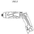
- FIG. 2shows a side view of the power tool in FIG. 1 ;
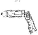
- FIG. 3depicts a side cross sectional view of the power tool in FIG. 1 ;
- FIG. 4provides a side view of the power tool being used in a straight shape
- FIG. 5presents a side cross sectional view of the power tool in FIG. 4 ;
- FIG. 6represents a perspective view of a power tool in accordance with another embodiment of the present invention, wherein a protruded elastomer is installed around an outer periphery of a lower front portion of a grip portion of the power tool;
- FIG. 7is a front view of a setting/display unit
- FIG. 8offers diagrams explaining a count mode and a count setting in the setting/display unit
- FIG. 9sets forth a diagram for explaining a function setting mode of the setting/display unit
- FIG. 10sets forth a circuit diagram of a control circuit for monitoring screw tightening operations
- FIG. 11shows a flow chart for explaining an exemplary operation of the control circuit
- FIG. 12illustrates a flow chart for explaining another exemplary operation of the control circuit.
- an electric screwdriverwill be described as an example of a power tool 1 .
- the power tool 1can be a cordless hammer drill, a cordless drill/driver, or any other device obvious to one skilled in the art, without departing from the scope of the present invention.
- the power tool 1includes a driving unit 24 for performing screw tightening operations; a motor 11 for rotatably driving the driving unit 24 ; a trigger switch SW for turning on and off the motor 11 ; an attachable/detachable rechargeable battery pack 9 ; and a housing 3 for accommodating therein the above components.
- the driving unit 24is provided with a clutch mechanism. As the screw tightening operation proceeds, a torque applied to a driver bit pressed against a screw to be tightened increases and reaches a specific level. At that moment, the clutch is driven to disengage a mechanical connection between the motor 11 and the corresponding driver bit.
- a screw tightening completion detection unit 4detects that and transmits a shut-off signal (pulse signal) to a screw tightening count unit 5 .
- the housing 3 of a power tool main body 2can have a straight shape (T-shape) or an L-shape configuration for the balance of the main body 2 .
- a grip portion 12 and a body portion 13are connected rotatably about a rotational shaft portion 14 such that an angle therebetween can be changed freely.
- the rotational shaft 14allows the housing 3 of the main body 2 to be varied between the straight shape and the L-shape.
- a structure for changing the angle about the rotational shaft portion 14 and maintaining changed anglecan be configured properly without being limited to a specific one.
- the shape of the housing 3can be varied to provide an easy grip for an operator.
- the L-shaped housing 3is suitable for a horizontal or an upward screw tightening operation
- the straight-shaped housing 3is suitable for a downward screw tightening operation.
- the body portion 13 of the housing 3has the driving unit 24 , the motor 11 , the trigger switch SW, a lock switch 15 for maintaining the off state of the trigger switch SW, and a control switch 16 for adjusting an output torque and a rotation speed of the motor 11 .
- Installed at the clutch side of the motor 11is a photo-interrupter 4 a constituting the screw tightening completion detection unit 4 .
- the screw tightening completion detection unit 4is not limited to employing the photo-interrupter 4 a for detecting the completion of the screw tightening but may also employ a distance sensor or use a motor off signal.
- the grip portion 12 of the housing 3is provided with a battery pack mounting portion 17 for detachably mounting the battery pack 9 . Further, a control circuit board 8 a for monitoring the screw tightening operations is installed in the grip portion 12 . Moreover, as illustrated in FIG. 5 , a microcomputer 5 a constituting the screw tightening count unit 5 is installed inside the grip portion 12 near the rotational shaft portion 14 . The microcomputer 5 a may also be installed inside a lower front portion 12 a of the grip portion 12 .
- the lower front portion 12 a of the grip portion 12is provided with a setting/display unit 6 a constituting a screw tightening number setting unit 6 ; and a piezoelectric buzzer 7 a constituting a screw tightening completion notifying unit 7 .
- the lower front portion 12 a of the grip portion 12is protruded more forward in a front direction F compared to a hand-grip portion of the grip portion 12 , so that the lower front portion 12 a is not touched by a hand when the grip portion 12 is held by the hand. Accordingly, an operator can easily hold the grip portion 12 without touching the setting/display unit 6 a that is exposed at the lower front portion 12 a.
- the lower front portion 12 a of the grip portion 12indicates a portion positioned below the hand-grip portion of the grip portion 12 , while facing forward along the front direction F when the grip portion 12 is held by a hand. Further, the front direction F is the same as that along which an output side (driven bit) of the body portion 13 directs when the body portion 13 and the grip portion 12 form the L-shape by bending.
- the setting/display unit 6 aexposed at the lower front portion 12 a of the grip portion 12 , includes a display part 18 and setting buttons 19 .
- the display portion 18has an LED part 18 a for displaying numerical values and an upper and a lower lamp 18 b and 18 c for indicating selected count-up and count-down mode, respectively.
- the setting buttons 19have a “mode” button 19 a , a “reset” button 19 d , a “+” button 19 b and a “ ⁇ ” button 19 c .
- a reference numeral 20 in FIG. 7represents an LED light for supporting an operation in the dark environment.
- the LED part 18 a of the display portion 18is turned on as shown in FIG. 8 , so that it is possible to set or change a required number of tightening operations.
- the “mode” button 19 ais briefly pressed, a count-up/down selection mode is executed in which one of the upper lamp 18 b and the lower lamp 18 c blinks. If the upper lamp 18 b blinks by pressing the “+” button 19 b , the count-up mode is selected.
- the count-down modeis selected.
- the “mode” button 19 ais briefly pressed again, the selected mode is stored, and a setting value change mode is executed in which the LED part 18 a blinks.
- the number of tightening operationscan be set by pressing the “+” button 19 b or the “ ⁇ ” button 19 c .
- the number of tightening operationscan be set up to 99.
- the “mode” button 19 ais briefly pressed again, the setting value is stored. An order of executing the count up/down selection mode and the setting value change mode can be changed.
- a sound setting mode illustrated in FIG. 9is initiated and in this example, “F1” is displayed on the LED part 18 a .
- the “mode” button 19 ais pressed while one of the alarm sounds having a specific pitch is produced, the alarm sound having that pitch is selected and stored. As a result, it is possible to prevent multiple operators working in a same area from being confused by the alarm sounds of adjacent operators.
- the “mode” button 19 ais briefly pressed, the character displayed on the LED part 18 a is switched from “F1” to “F2”, and an erroneous count correcting mode is executed. If an erroneous count occurs due to stoppage of the motor 11 during the operation for example, the erroneous count can be corrected by pressing the “+” button 19 b , the “ ⁇ ” button 19 c and the “reset” button 19 d during the state where the LED 18 A displays “F2”.
- a double tightening count prevention functionis provided.
- the double tightening count prevention functionis executed when a double tightening operation (tightening check-out operation) that tightens a same screw twice is carried out within a predetermined time period. For example, if the count time is set to one second, only a tightening operation performed not within one second after the completion of the previous one is counted, whereas a second tightening operation performed within one second is not counted.
- FIG. 10shows a circuit diagram of a control circuit 8 , formed on the control circuit board 8 a , for monitoring screw tightening operations.
- a CPU 21When the trigger switch SW is turned on, a CPU 21 is supplied with a power supply voltage.
- the CPU 21has a power self-maintenance unit 22 for self-holding the power supplied thereto and a battery voltage measuring unit 25 for detecting the voltage of the supplied power.
- the CPU 21receives a shut-off signal from the photo-interrupter 4 a serving as the screw tightening completion detection unit 4 and a input setting signal from the setting/display unit 6 a .
- Reference numerals 50 , 51 and 52 in FIG. 10indicate a circuit voltage driving device, a motor driving FET and a break FET, respectively.
- Step 1when the trigger switch SW is turned on (Step 1 ), an initial process (circuit conduction and storage retrieval) is performed (Step 2 ).
- Step 2an initial process (circuit conduction and storage retrieval) is performed (Step 2 ).
- the display portion 18is turned on (Step 3 ) only when a battery pack output voltage (referred to as “battery voltage” hereinafter) is determined to be higher than a first threshold.
- the display portion 18displays thereon preset data (e.g., a preset number (initial value of count value) “10” in case of the count-down mode is selected).
- the motor 11is driven to perform the screw tightening operation (Step 4 ).
- the shut-off signal(pulse signal) is transmitted from the photo-interrupter 4 a to the CPU 21 , and the CPU 21 automatically stops the motor 11 .
- the number of tightening operationsi.e., “1” is counted by the screw tightening count unit 5 , so that the number displayed on the display portion 18 is switched from “10 to “9” (if the count-up mode was selected, the number displayed on the display portion 18 is switched from “0” to “1”).
- the alarm soundis produced from the piezoelectric buzzer 7 a , thereby notifying the operator of the completion of the tightening operations and preventing the operator from forgetting to tighten all the screws.
- the number displayed on the setting/display unit 6 aautomatically returns to the original number (e.g., “10”) (Step 5 ), thereby completing the corresponding screw tightening operations.
- Step 6it is first determined whether or not the battery voltage is higher than the first threshold, as shown in FIG. 12 . Only when the battery voltage is determined to be higher than the first threshold, the display portion 18 is turned on (Step 6 ). Next, when a new setting number is inputted, the newly inputted number is stored as a renewed number of tightening operations (Step 7 ). Meanwhile, if a specific period of time elapses without receiving a setting number, the power to the setting/display unit 6 a is disconnected to turn off the display portion 18 (Step 8 ).
- the power tool main body 2is equipped with the function of monitoring the screw tightening operations, thereby preventing an operator from forgetting to tighten all the screws. Accordingly, it is possible to avoid a defective assembly of a product and reduce an operator's burden accompanied by the potential forgetfulness of the screw tightening operation, thereby improving the accuracy and the efficiency of the screw tightening operations. Moreover, unlike in the prior art, there is no need to connect the power tool and the controller via the power cord. Especially, by providing the function of monitoring a screw tightening operation to the cordless rechargeable power tool having the attachable/detachable battery pack 9 of this example, the working area is no longer restricted. Consequently, the advantages of the cordless type can be fully utilized.
- the body portion 13 or the grip portion 12 of the housing 3need not to be enlarged and, also, gripping of the grip portion 12 is not hindered.
- the grip portion 12is not subject to great impacts or vibrations, compared to the heavy body portion 13 having therein the motor 11 , when the power tool 1 is dropped during its use. Therefore, it is possible to effectively prevent damages from being inflicted on the components of the screw tightening number setting unit 6 and the screw tightening completion notifying unit 7 .
- the power from the battery pack 9 to the setting/display unit 6 ais disconnected after a specific period of time elapses after the completion of the screw tightening operations. Therefore, the waste of the battery in the battery pack 9 can be avoided. Also, when a measured battery voltage is lower than or equal to a specific value (first threshold), the power to the setting/display unit 6 a is disconnected. Further, when a measured battery voltage is lower than or equal to the second threshold greater than the first threshold, the power to the motor 11 is stopped. Accordingly, power can be saved and, further, the burden on the battery pack 9 can be reduced.
- first thresholda specific value
- the setting/display unit 6 a of the control circuit 8is provided with a hold switch 10 for preventing a data change on the display portion 18 , as shown in FIG. 10 .
- a manipulation portion of the hold switch 10is provided on a side surface near the setting/display unit 6 a disposed at the lower front portion 12 a of the grip portion 12 (see FIG. 1 ).
- the hold switch 10By keeping the hold switch 10 to be OFF, the number of tightening operations will not change even if the setting/display unit 6 a is touched accidentally during the operation. In other words, while the hold switch 10 is OFF, the change of numerals is disallowed even when the buttons of the display portion 18 are pressed.
- the number of tightening operationsmay be changed by accidentally touching the buttons of the setting/display unit 6 a during the operation.
- the setting change during the operationcan be prevented by activating the hold function of the embodiment of the present invention. As a result, the number of tightening operations can be precisely managed while maintaining the setting state.
- a circuitcan be configured to cancel manipulation signals from the setting/display unit 6 a when a signal for turning the motor 11 ON is inputted. Accordingly, even when the buttons of the setting/display unit 6 a are accidentally pressed during the operation, the setting data or the count number will not change, as in the case of activating the hold switch 10 .
- the CPU 21 in the present embodimenthas a storage (not shown) for storing therein the count number or the setting data of the setting/display unit 6 a .
- the display of the number of tightening operations on the setting/display unit 6 a provided at the lower front portion 12 a of the grip portion 12can be displayed upside down to accommodate the angle change between the straight shape and the “L” shape of the power tool 1 . Accordingly, when an operator use the power tool 1 by holding the grip portion 12 heading either upward or downward, it is easy for the operator to read data on the setting/display unit 6 a and perform a smooth screw tightening operations. Displaying characters or symbols upside down can be done by, e.g., pressing together the “+” button 19 b and the “ ⁇ ” button 19 c . By doing so, an embedded changeover switch is switched over, and a display control circuit allows the characters or the symbols to be displayed on the display portion upside down.
- FIG. 6shows another embodiment of the present invention which describes an example where a protruded elastomer 30 is installed around an outer periphery of the lower front portion 12 a of the grip portion 12 .
- Elastomer 30is designed to absorb the impacts when the power tool main body 2 is dropped during its use. Accordingly, the grip portion 12 is protected from large impacts or vibrations and, it is also possible to prevent the breakage of the screw tightening number setting unit 6 and its components (the setting/display unit 6 a , the piezoelectric buzzer 7 a and the control circuit 8 ).
- the durability of the power tool 1can be further enhanced with the addition of an elastomer 30 so that the power tool 1 can be used under severe conditions.
- the power tool of the present inventioncan be adaptively used in various product manufacturing processes or construction sites.
- the elastomer 30can be simply provided to the housing by 2-color injection molding of the elastomer resin and molding resin of the housing.
- the power tool of the present inventioncan be applied both to a cord type power tool and a rechargeable type power tool.
Landscapes
- Engineering & Computer Science (AREA)
- Mechanical Engineering (AREA)
- Details Of Spanners, Wrenches, And Screw Drivers And Accessories (AREA)
Abstract
Description
Claims (7)
Applications Claiming Priority (2)
| Application Number | Priority Date | Filing Date | Title |
|---|---|---|---|
| JP2006-236540 | 2006-08-31 | ||
| JP2006236540AJP4669455B2 (en) | 2006-08-31 | 2006-08-31 | Electric tool |
Publications (2)
| Publication Number | Publication Date |
|---|---|
| US20080257577A1 US20080257577A1 (en) | 2008-10-23 |
| US7673701B2true US7673701B2 (en) | 2010-03-09 |
Family
ID=38814634
Family Applications (1)
| Application Number | Title | Priority Date | Filing Date |
|---|---|---|---|
| US11/892,976Expired - Fee RelatedUS7673701B2 (en) | 2006-08-31 | 2007-08-29 | Power tool having control means for monitoring screw tightening operations |
Country Status (4)
| Country | Link |
|---|---|
| US (1) | US7673701B2 (en) |
| EP (1) | EP1894677B1 (en) |
| JP (1) | JP4669455B2 (en) |
| CN (1) | CN101134307B (en) |
Cited By (16)
| Publication number | Priority date | Publication date | Assignee | Title |
|---|---|---|---|---|
| US20100163265A1 (en)* | 2008-12-26 | 2010-07-01 | Omron Corporation | Electrical power tool |
| US8446120B2 (en) | 2011-05-19 | 2013-05-21 | Black & Decker Inc. | Electronic switching module for a power tool |
| US20130186666A1 (en)* | 2012-01-23 | 2013-07-25 | Max Co., Ltd. | Rotary tool |
| US20130240230A1 (en)* | 2012-03-16 | 2013-09-19 | Robert Bosch Gmbh | Hand-held power tool |
| US20130331229A1 (en)* | 2012-06-05 | 2013-12-12 | Robert Bosch Gmbh | Handheld screwing apparatus |
| US8919456B2 (en) | 2012-06-08 | 2014-12-30 | Black & Decker Inc. | Fastener setting algorithm for drill driver |
| US9450471B2 (en) | 2012-05-24 | 2016-09-20 | Milwaukee Electric Tool Corporation | Brushless DC motor power tool with combined PCB design |
| US9787159B2 (en) | 2013-06-06 | 2017-10-10 | Milwaukee Electric Tool Corporation | Brushless DC motor configuration for a power tool |
| US9908182B2 (en) | 2012-01-30 | 2018-03-06 | Black & Decker Inc. | Remote programming of a power tool |
| US9956676B2 (en) | 2013-01-09 | 2018-05-01 | Techtronic Power Tools Technology Limited | Tool with rotatable head |
| US10011006B2 (en) | 2013-08-08 | 2018-07-03 | Black & Decker Inc. | Fastener setting algorithm for drill driver |
| US20180215029A1 (en)* | 2017-01-31 | 2018-08-02 | Ingersoll-Rand Company | Quick double trigger configuration change |
| US10608501B2 (en) | 2017-05-24 | 2020-03-31 | Black & Decker Inc. | Variable-speed input unit having segmented pads for a power tool |
| US10821591B2 (en) | 2012-11-13 | 2020-11-03 | Milwaukee Electric Tool Corporation | High-power cordless, hand-held power tool including a brushless direct current motor |
| US12044530B2 (en) | 2008-07-10 | 2024-07-23 | Black & Decker Inc. | Communication protocol for remotely controlled laser devices |
| US12318906B2 (en) | 2012-06-08 | 2025-06-03 | Black & Decker Inc. | Power tool having multiple operating modes |
Families Citing this family (26)
| Publication number | Priority date | Publication date | Assignee | Title |
|---|---|---|---|---|
| US8281874B2 (en)* | 2007-06-25 | 2012-10-09 | Ryobi Ltd. | Power tool with vibration damping handle |
| JP5073380B2 (en)* | 2007-06-28 | 2012-11-14 | 株式会社マキタ | Electric driving tool |
| JP5133000B2 (en)* | 2007-06-28 | 2013-01-30 | 株式会社マキタ | Electric driving tool |
| USD586637S1 (en)* | 2008-05-14 | 2009-02-17 | Black & Decker Inc. | Screwdriver |
| CN101898339B (en)* | 2009-05-26 | 2013-04-17 | 海洋王照明科技股份有限公司 | Counting alarm electric device |
| USD606827S1 (en)* | 2009-06-18 | 2009-12-29 | 3M Innovative Properties Company | Small, portable power tool |
| JP5374300B2 (en)* | 2009-09-25 | 2013-12-25 | パナソニック株式会社 | Electric tool |
| CN102049762B (en)* | 2009-10-28 | 2012-08-22 | 南京德朔实业有限公司 | Electric hammer |
| US8631986B2 (en)* | 2009-12-04 | 2014-01-21 | Robert Bosch Gmbh | Fastener driver with an operating switch |
| DE102010002702A1 (en)* | 2010-03-09 | 2011-09-15 | Robert Bosch Gmbh | Electrical appliance, in particular electric hand tool |
| US9281770B2 (en) | 2012-01-27 | 2016-03-08 | Ingersoll-Rand Company | Precision-fastening handheld cordless power tools |
| JP6036320B2 (en)* | 2013-01-17 | 2016-11-30 | 日立工機株式会社 | Portable work machine |
| WO2014144353A1 (en)* | 2013-03-15 | 2014-09-18 | Milwaukee Electric Tool Corporation | Power tool operation recording and playback |
| US9156148B2 (en)* | 2013-05-10 | 2015-10-13 | Snap-On Incorporated | Preset electronic torque tool |
| DE102013210962B4 (en)* | 2013-06-12 | 2016-08-04 | Robert Bosch Gmbh | Hand tool with an electric motor drive and at least a first housing part |
| EP3103593B1 (en)* | 2014-02-04 | 2018-09-26 | Koki Holdings Kabushiki Kaisha | Abnormality reporting system |
| CN105328623B (en)* | 2014-06-30 | 2017-04-19 | 南京德朔实业有限公司 | Electric tool |
| CN105751132A (en)* | 2014-12-18 | 2016-07-13 | 苏州博来喜电器有限公司 | Impact wrench |
| CN105033921B (en)* | 2015-07-06 | 2017-09-29 | 中国第一汽车股份有限公司 | The method for preventing bolt leakage from tightening |
| JP2015221494A (en)* | 2015-09-08 | 2015-12-10 | 日東工器株式会社 | Screw member tightening tool and count device |
| CN105590764A (en)* | 2016-01-29 | 2016-05-18 | 国网浙江省电力公司嘉兴供电公司 | Ring network cabinet electric rotation-type operation handle |
| JP6654269B2 (en)* | 2017-12-18 | 2020-02-26 | 日東工器株式会社 | Tool and tool control circuit and control method |
| DE102020211889A1 (en)* | 2020-09-23 | 2022-03-24 | Robert Bosch Gesellschaft mit beschränkter Haftung | hand tool |
| CN113770961B (en)* | 2021-09-22 | 2024-03-12 | 上海优拜机械股份有限公司 | Wireless torque wrench confirmation method, system, device and storage medium |
| USD996178S1 (en)* | 2022-06-22 | 2023-08-22 | Jiangsu Dongcheng Tools Technology Co., Ltd. | Doubleheaded handheld power tool for grinding drilling screwing and other operations on workpieces |
| USD1052986S1 (en)* | 2024-08-29 | 2024-12-03 | Heracles (Shenzhen) Intelligent Technology Co., Ltd. | Electric screw driver |
Citations (22)
| Publication number | Priority date | Publication date | Assignee | Title |
|---|---|---|---|---|
| JPS5955670A (en) | 1982-09-24 | 1984-03-30 | Fuji Xerox Co Ltd | Processor of picture signal |
| JPS62124881A (en) | 1985-11-25 | 1987-06-06 | 松下電工株式会社 | Electric driver |
| JPS62159286A (en) | 1986-01-07 | 1987-07-15 | Hitachi Ltd | Cursor control method and three-dimensional graphic display device |
| JPS6383277A (en) | 1986-09-29 | 1988-04-13 | Canon Inc | Device for forming functional deposited film by microwave plasma cvd method |
| JPS63186579A (en) | 1987-01-26 | 1988-08-02 | Daikin Ind Ltd | Induction motor drive control device |
| US4813312A (en)* | 1986-06-14 | 1989-03-21 | Raimund Wilhelm | Power-wrench, a boiling spindle and an operational method |
| US5014793A (en)* | 1989-04-10 | 1991-05-14 | Measurement Specialties, Inc. | Variable speed DC motor controller apparatus particularly adapted for control of portable-power tools |
| US5277261A (en)* | 1992-01-23 | 1994-01-11 | Makita Corporation | Tightening tool |
| US5903462A (en)* | 1996-10-17 | 1999-05-11 | The United States Of America As Represented By The Administrator Of The National Aeronautics And Space Administration | Computer implemented method, and apparatus for controlling a hand-held tool |
| JPH11196397A (en) | 1997-12-26 | 1999-07-21 | Canon Inc | Display device and communication system |
| USH1821H (en)* | 1997-07-02 | 1999-12-07 | Caterpillar, Incorporated | Method and apparatus for operating a driver and an associated number of work tools |
| JP2000108047A (en) | 1998-09-30 | 2000-04-18 | Nakamura Seisakusho:Kk | Torque wrench with counting function |
| JP2000250434A (en) | 1999-02-26 | 2000-09-14 | Sharp Corp | Portable information equipment and gravity direction detector |
| JP2001269874A (en) | 2000-03-24 | 2001-10-02 | Makita Corp | Fastening tool |
| US20020050364A1 (en) | 2000-03-16 | 2002-05-02 | Hitoshi Suzuki | Power tools |
| US20020134172A1 (en)* | 1999-03-16 | 2002-09-26 | Masakazu Yamada | Reading method of crew rotation angle of hand-held impact wrench, hand-vibration detection method, tightening evaluation and control method of hand-held power screw loosening tool |
| US6457535B1 (en)* | 1999-04-30 | 2002-10-01 | Matsushita Electric Works, Ltd. | Impact rotary tool |
| US6536536B1 (en)* | 1999-04-29 | 2003-03-25 | Stephen F. Gass | Power tools |
| JP2005040933A (en) | 2003-07-25 | 2005-02-17 | Matsushita Electric Works Ltd | Mobile power tool |
| US20050045354A1 (en) | 2003-08-26 | 2005-03-03 | Tadashi Arimura | Electric tool |
| US20050121209A1 (en) | 2003-11-11 | 2005-06-09 | Matsushita Electric Works, Ltd. | Transportable power tool |
| US20080173139A1 (en)* | 2006-08-31 | 2008-07-24 | Matsushita Electric Works Ltd. | Power tool |
Family Cites Families (7)
| Publication number | Priority date | Publication date | Assignee | Title |
|---|---|---|---|---|
| JPH02311277A (en)* | 1989-05-26 | 1990-12-26 | Toshiba Corp | Inspection for forgetting of screw tightening and device therefor |
| DE19961374A1 (en)* | 1999-12-20 | 2001-06-21 | Volkswagen Ag | Device to form screw connections; has external data processing and memory unit to provide screwing parameter and measuring units to measure parameter after screwing for transmission to data unit |
| DE20117889U1 (en)* | 2001-11-02 | 2002-01-24 | Hilti Ag, Schaan | Cordless screwdriver |
| GB2382048A (en)* | 2001-11-20 | 2003-05-21 | Black & Decker Inc | Pivoting electrical connection for a power tool |
| TWM248566U (en)* | 2003-12-18 | 2004-11-01 | Mobiletron Electronics Co Ltd | Electric tool |
| CN1640625A (en)* | 2004-01-16 | 2005-07-20 | 金统立工业股份有限公司 | Torque wrench capable of counting and displaying |
| DE102004032787A1 (en)* | 2004-07-06 | 2006-02-16 | Robert Bosch Gmbh | Hand operated power tool e.g. nut runner, impact screwdriver, has adjustable wheel with lighting screen provided at free end of handle |
- 2006
- 2006-08-31JPJP2006236540Apatent/JP4669455B2/enactiveActive
- 2007
- 2007-08-29USUS11/892,976patent/US7673701B2/ennot_activeExpired - Fee Related
- 2007-08-29EPEP07016945.3Apatent/EP1894677B1/enactiveActive
- 2007-08-30CNCN2007101471045Apatent/CN101134307B/ennot_activeExpired - Fee Related
Patent Citations (26)
| Publication number | Priority date | Publication date | Assignee | Title |
|---|---|---|---|---|
| JPS5955670A (en) | 1982-09-24 | 1984-03-30 | Fuji Xerox Co Ltd | Processor of picture signal |
| JPS62124881A (en) | 1985-11-25 | 1987-06-06 | 松下電工株式会社 | Electric driver |
| JPS62159286A (en) | 1986-01-07 | 1987-07-15 | Hitachi Ltd | Cursor control method and three-dimensional graphic display device |
| US4813312A (en)* | 1986-06-14 | 1989-03-21 | Raimund Wilhelm | Power-wrench, a boiling spindle and an operational method |
| JPS6383277A (en) | 1986-09-29 | 1988-04-13 | Canon Inc | Device for forming functional deposited film by microwave plasma cvd method |
| JPS63186579A (en) | 1987-01-26 | 1988-08-02 | Daikin Ind Ltd | Induction motor drive control device |
| US5014793A (en)* | 1989-04-10 | 1991-05-14 | Measurement Specialties, Inc. | Variable speed DC motor controller apparatus particularly adapted for control of portable-power tools |
| US5277261A (en)* | 1992-01-23 | 1994-01-11 | Makita Corporation | Tightening tool |
| US5903462A (en)* | 1996-10-17 | 1999-05-11 | The United States Of America As Represented By The Administrator Of The National Aeronautics And Space Administration | Computer implemented method, and apparatus for controlling a hand-held tool |
| USH1821H (en)* | 1997-07-02 | 1999-12-07 | Caterpillar, Incorporated | Method and apparatus for operating a driver and an associated number of work tools |
| JPH11196397A (en) | 1997-12-26 | 1999-07-21 | Canon Inc | Display device and communication system |
| JP2000108047A (en) | 1998-09-30 | 2000-04-18 | Nakamura Seisakusho:Kk | Torque wrench with counting function |
| JP2000250434A (en) | 1999-02-26 | 2000-09-14 | Sharp Corp | Portable information equipment and gravity direction detector |
| US20020134172A1 (en)* | 1999-03-16 | 2002-09-26 | Masakazu Yamada | Reading method of crew rotation angle of hand-held impact wrench, hand-vibration detection method, tightening evaluation and control method of hand-held power screw loosening tool |
| US6536536B1 (en)* | 1999-04-29 | 2003-03-25 | Stephen F. Gass | Power tools |
| US6457535B1 (en)* | 1999-04-30 | 2002-10-01 | Matsushita Electric Works, Ltd. | Impact rotary tool |
| US20020050364A1 (en) | 2000-03-16 | 2002-05-02 | Hitoshi Suzuki | Power tools |
| US6607041B2 (en)* | 2000-03-16 | 2003-08-19 | Makita Corporation | Power tools |
| JP2001269874A (en) | 2000-03-24 | 2001-10-02 | Makita Corp | Fastening tool |
| JP2005040933A (en) | 2003-07-25 | 2005-02-17 | Matsushita Electric Works Ltd | Mobile power tool |
| CN100337793C (en) | 2003-07-25 | 2007-09-19 | 松下电工株式会社 | Movable electric tool |
| US20050045354A1 (en) | 2003-08-26 | 2005-03-03 | Tadashi Arimura | Electric tool |
| JP2005066785A (en) | 2003-08-26 | 2005-03-17 | Matsushita Electric Works Ltd | Power tool |
| US20050121209A1 (en) | 2003-11-11 | 2005-06-09 | Matsushita Electric Works, Ltd. | Transportable power tool |
| JP2005144564A (en) | 2003-11-11 | 2005-06-09 | Matsushita Electric Works Ltd | Portable electric tool |
| US20080173139A1 (en)* | 2006-08-31 | 2008-07-24 | Matsushita Electric Works Ltd. | Power tool |
Cited By (47)
| Publication number | Priority date | Publication date | Assignee | Title |
|---|---|---|---|---|
| US12044530B2 (en) | 2008-07-10 | 2024-07-23 | Black & Decker Inc. | Communication protocol for remotely controlled laser devices |
| US8276685B2 (en)* | 2008-12-26 | 2012-10-02 | Omron Corporation | Electrical power tool |
| US20100163265A1 (en)* | 2008-12-26 | 2010-07-01 | Omron Corporation | Electrical power tool |
| US9401250B2 (en) | 2011-05-19 | 2016-07-26 | Black & Decker, Inc. | Electronic switching module for a power tool |
| US8446120B2 (en) | 2011-05-19 | 2013-05-21 | Black & Decker Inc. | Electronic switching module for a power tool |
| US9508498B2 (en) | 2011-05-19 | 2016-11-29 | Black & Decker, Inc. | Electronic switching module for a power tool |
| US10256697B2 (en) | 2011-05-19 | 2019-04-09 | Black & Decker Inc. | Electronic switching module for a power tool |
| US9406457B2 (en) | 2011-05-19 | 2016-08-02 | Black & Decker Inc. | Electronic switching module for a power tool |
| US9000882B2 (en) | 2011-05-19 | 2015-04-07 | Black & Decker Inc. | Electronic switching module for a power tool |
| US10651706B2 (en) | 2011-05-19 | 2020-05-12 | Black & Decker Inc. | Control unit for a power tool |
| US9296095B2 (en)* | 2012-01-23 | 2016-03-29 | Max Co., Ltd. | Rotary tool |
| US20130186666A1 (en)* | 2012-01-23 | 2013-07-25 | Max Co., Ltd. | Rotary tool |
| US11712741B2 (en) | 2012-01-30 | 2023-08-01 | Black & Decker Inc. | Remote programming of a power tool |
| US9908182B2 (en) | 2012-01-30 | 2018-03-06 | Black & Decker Inc. | Remote programming of a power tool |
| US10661355B2 (en) | 2012-01-30 | 2020-05-26 | Black & Decker Inc. | Remote programming of a power tool |
| US20130240230A1 (en)* | 2012-03-16 | 2013-09-19 | Robert Bosch Gmbh | Hand-held power tool |
| US10668612B2 (en)* | 2012-03-16 | 2020-06-02 | Robert Bosch Gmbh | Hand-held power tool |
| US11031843B2 (en) | 2012-05-24 | 2021-06-08 | Milwaukee Electric Tool Corporation | Brushless DC motor power tool with combined PCB design |
| US9960656B2 (en) | 2012-05-24 | 2018-05-01 | Milwaukee Electric Tool Corporation | Brushless DC motor power tool with combined PCB design |
| US11923752B2 (en) | 2012-05-24 | 2024-03-05 | Milwaukee Electric Tool Corporation | Brushless DC motor power tool with combined PCB design |
| US10530220B2 (en) | 2012-05-24 | 2020-01-07 | Milwaukee Electric Tool Corporation | Brushless DC motor power tool with combined PCB design |
| US9450471B2 (en) | 2012-05-24 | 2016-09-20 | Milwaukee Electric Tool Corporation | Brushless DC motor power tool with combined PCB design |
| US9774229B1 (en) | 2012-05-24 | 2017-09-26 | Milwaukee Electric Tool Corporation | Brushless DC motor power tool with combined PCB design |
| CN103465211B (en)* | 2012-06-05 | 2017-07-11 | 罗伯特·博世有限公司 | Hand-held device for screwing up |
| DE102012209447B4 (en) | 2012-06-05 | 2022-03-17 | Robert Bosch Gmbh | manual screwing device |
| US9808919B2 (en)* | 2012-06-05 | 2017-11-07 | Robert Bosch Gmbh | Handheld screwing apparatus |
| CN103465211A (en)* | 2012-06-05 | 2013-12-25 | 罗伯特·博世有限公司 | Handheld screwing apparatus |
| US20130331229A1 (en)* | 2012-06-05 | 2013-12-12 | Robert Bosch Gmbh | Handheld screwing apparatus |
| US12318906B2 (en) | 2012-06-08 | 2025-06-03 | Black & Decker Inc. | Power tool having multiple operating modes |
| US8919456B2 (en) | 2012-06-08 | 2014-12-30 | Black & Decker Inc. | Fastener setting algorithm for drill driver |
| US12011812B2 (en) | 2012-11-13 | 2024-06-18 | Milwaukee Electric Tool Corporation | High-power cordless, hand-held power tool including a brushless direct current motor |
| US12370664B2 (en) | 2012-11-13 | 2025-07-29 | Milwaukee Electric Tool Corporation | High-power cordless, hand-held power tool including a brushless direct current motor |
| US10821591B2 (en) | 2012-11-13 | 2020-11-03 | Milwaukee Electric Tool Corporation | High-power cordless, hand-held power tool including a brushless direct current motor |
| US12377529B2 (en) | 2012-11-13 | 2025-08-05 | Milwaukee Electric Tool Corporation | High-power cordless, hand-held power tool including a brushless direct current motor |
| US11141851B2 (en) | 2012-11-13 | 2021-10-12 | Milwaukee Electric Tool Corporation | High-power cordless, hand-held power tool including a brushless direct current motor |
| US11370099B2 (en) | 2012-11-13 | 2022-06-28 | Milwaukee Electric Tool Corporation | High-power cordless, hand-held power tool including a brushless direct current motor |
| US11673248B2 (en) | 2012-11-13 | 2023-06-13 | Milwaukee Electric Tool Corporation | High-power cordless, hand-held power tool including a brushless direct current motor |
| US9956676B2 (en) | 2013-01-09 | 2018-05-01 | Techtronic Power Tools Technology Limited | Tool with rotatable head |
| US10978933B2 (en) | 2013-06-06 | 2021-04-13 | Milwaukee Electric Tool Corporation | Brushless DC motor configuration for a power tool |
| US11777369B2 (en) | 2013-06-06 | 2023-10-03 | Milwaukee Electric Tool Corporation | Brushless dc motor configuration for a power tool |
| US10693345B2 (en) | 2013-06-06 | 2020-06-23 | Milwaukee Electric Tool Corporation | Brushless DC motor configuration for a power tool |
| US10348159B2 (en) | 2013-06-06 | 2019-07-09 | Milwaukee Electric Tool Corporation | Brushless DC motor configuration for a power tool |
| US12081104B2 (en) | 2013-06-06 | 2024-09-03 | Milwaukee Electric Tool Corporation | Brushless DC motor configuration for a power tool |
| US9787159B2 (en) | 2013-06-06 | 2017-10-10 | Milwaukee Electric Tool Corporation | Brushless DC motor configuration for a power tool |
| US10011006B2 (en) | 2013-08-08 | 2018-07-03 | Black & Decker Inc. | Fastener setting algorithm for drill driver |
| US20180215029A1 (en)* | 2017-01-31 | 2018-08-02 | Ingersoll-Rand Company | Quick double trigger configuration change |
| US10608501B2 (en) | 2017-05-24 | 2020-03-31 | Black & Decker Inc. | Variable-speed input unit having segmented pads for a power tool |
Also Published As
| Publication number | Publication date |
|---|---|
| EP1894677B1 (en) | 2014-05-07 |
| CN101134307A (en) | 2008-03-05 |
| EP1894677A2 (en) | 2008-03-05 |
| JP2008055564A (en) | 2008-03-13 |
| JP4669455B2 (en) | 2011-04-13 |
| US20080257577A1 (en) | 2008-10-23 |
| CN101134307B (en) | 2010-06-02 |
| EP1894677A3 (en) | 2010-08-04 |
Similar Documents
| Publication | Publication Date | Title |
|---|---|---|
| US7673701B2 (en) | Power tool having control means for monitoring screw tightening operations | |
| US7703330B2 (en) | Power tool | |
| US11420310B2 (en) | Power tool | |
| US7832286B2 (en) | Torque wrench | |
| US20190210200A1 (en) | Torque wrench with shock absorption | |
| US10807219B2 (en) | Depth and angle sensor attachment for a power tool | |
| US20050121209A1 (en) | Transportable power tool | |
| NZ574230A (en) | Cordless motor assisted torque wrench | |
| JP7556771B2 (en) | Electric work machine | |
| US20150336248A1 (en) | Power Drill Having Torque Setting Mechanism | |
| EP3230010B1 (en) | Power tool with telescopic output shaft | |
| KR101700425B1 (en) | Portable electric power tool having emergency shut off device | |
| WO2023097281A1 (en) | Grinder including enhanced sensing and component detection | |
| US10850383B1 (en) | Tool user interface ring | |
| TWI732586B (en) | Detection device of electrical tools | |
| JP2012139766A (en) | Tightening tool and predetermined work detecting unit | |
| JP2009262273A (en) | Impact rotary tool | |
| WO2024185462A1 (en) | Auxiliary handle, handheld electric tool comprising same, handheld electric tool control method using auxiliary handle, and control program | |
| WO2024185455A1 (en) | Usage status management apparatus for electric grip tool and usage status management system provided therein | |
| US20220168875A1 (en) | Torque application tool | |
| JP2024124985A (en) | Electric gripping tool, and control method and control program for electric gripping tool |
Legal Events
| Date | Code | Title | Description |
|---|---|---|---|
| AS | Assignment | Owner name:MATSUSHITA ELECTRIC WORKS, LTD., JAPAN Free format text:ASSIGNMENT OF ASSIGNORS INTEREST;ASSIGNORS:TANAKA, NAOTAKE;MIYAZAKI, HIROSHI;KATOU, MAKOTO;REEL/FRAME:019809/0427;SIGNING DATES FROM 20070727 TO 20070730 Owner name:MATSUSHITA ELECTRIC WORKS, LTD.,JAPAN Free format text:ASSIGNMENT OF ASSIGNORS INTEREST;ASSIGNORS:TANAKA, NAOTAKE;MIYAZAKI, HIROSHI;KATOU, MAKOTO;SIGNING DATES FROM 20070727 TO 20070730;REEL/FRAME:019809/0427 | |
| AS | Assignment | Owner name:PANASONIC ELECTRIC WORKS CO., LTD., JAPAN Free format text:CHANGE OF NAME;ASSIGNOR:MATSUSHITA ELECTRIC WORKS, LTD.;REEL/FRAME:022206/0574 Effective date:20081001 Owner name:PANASONIC ELECTRIC WORKS CO., LTD.,JAPAN Free format text:CHANGE OF NAME;ASSIGNOR:MATSUSHITA ELECTRIC WORKS, LTD.;REEL/FRAME:022206/0574 Effective date:20081001 | |
| FEPP | Fee payment procedure | Free format text:PAYOR NUMBER ASSIGNED (ORIGINAL EVENT CODE: ASPN); ENTITY STATUS OF PATENT OWNER: LARGE ENTITY | |
| FPAY | Fee payment | Year of fee payment:4 | |
| FEPP | Fee payment procedure | Free format text:MAINTENANCE FEE REMINDER MAILED (ORIGINAL EVENT CODE: REM.) | |
| LAPS | Lapse for failure to pay maintenance fees | Free format text:PATENT EXPIRED FOR FAILURE TO PAY MAINTENANCE FEES (ORIGINAL EVENT CODE: EXP.) | |
| STCH | Information on status: patent discontinuation | Free format text:PATENT EXPIRED DUE TO NONPAYMENT OF MAINTENANCE FEES UNDER 37 CFR 1.362 | |
| FP | Lapsed due to failure to pay maintenance fee | Effective date:20180309 |