US7672763B1 - Method for coupling a telematics device to a vehicle using an in-vehicle wiring harness with multiple adaptors for an on-board diagnostic connector - Google Patents
Method for coupling a telematics device to a vehicle using an in-vehicle wiring harness with multiple adaptors for an on-board diagnostic connectorDownload PDFInfo
- Publication number
- US7672763B1 US7672763B1US12/261,751US26175108AUS7672763B1US 7672763 B1US7672763 B1US 7672763B1US 26175108 AUS26175108 AUS 26175108AUS 7672763 B1US7672763 B1US 7672763B1
- Authority
- US
- United States
- Prior art keywords
- connector
- vehicle
- diagnostic
- coupling
- telematics device
- Prior art date
- Legal status (The legal status is an assumption and is not a legal conclusion. Google has not performed a legal analysis and makes no representation as to the accuracy of the status listed.)
- Expired - Lifetime
Links
Images


Classifications
- G—PHYSICS
- G07—CHECKING-DEVICES
- G07C—TIME OR ATTENDANCE REGISTERS; REGISTERING OR INDICATING THE WORKING OF MACHINES; GENERATING RANDOM NUMBERS; VOTING OR LOTTERY APPARATUS; ARRANGEMENTS, SYSTEMS OR APPARATUS FOR CHECKING NOT PROVIDED FOR ELSEWHERE
- G07C5/00—Registering or indicating the working of vehicles
- G07C5/008—Registering or indicating the working of vehicles communicating information to a remotely located station
- B—PERFORMING OPERATIONS; TRANSPORTING
- B60—VEHICLES IN GENERAL
- B60R—VEHICLES, VEHICLE FITTINGS, OR VEHICLE PARTS, NOT OTHERWISE PROVIDED FOR
- B60R16/00—Electric or fluid circuits specially adapted for vehicles and not otherwise provided for; Arrangement of elements of electric or fluid circuits specially adapted for vehicles and not otherwise provided for
- B60R16/02—Electric or fluid circuits specially adapted for vehicles and not otherwise provided for; Arrangement of elements of electric or fluid circuits specially adapted for vehicles and not otherwise provided for electric constitutive elements
- B60R16/0207—Wire harnesses
- H—ELECTRICITY
- H01—ELECTRIC ELEMENTS
- H01R—ELECTRICALLY-CONDUCTIVE CONNECTIONS; STRUCTURAL ASSOCIATIONS OF A PLURALITY OF MUTUALLY-INSULATED ELECTRICAL CONNECTING ELEMENTS; COUPLING DEVICES; CURRENT COLLECTORS
- H01R12/00—Structural associations of a plurality of mutually-insulated electrical connecting elements, specially adapted for printed circuits, e.g. printed circuit boards [PCB], flat or ribbon cables, or like generally planar structures, e.g. terminal strips, terminal blocks; Coupling devices specially adapted for printed circuits, flat or ribbon cables, or like generally planar structures; Terminals specially adapted for contact with, or insertion into, printed circuits, flat or ribbon cables, or like generally planar structures
- H01R12/50—Fixed connections
- H01R12/59—Fixed connections for flexible printed circuits, flat or ribbon cables or like structures
- H01R12/65—Fixed connections for flexible printed circuits, flat or ribbon cables or like structures characterised by the terminal
- H01R12/67—Fixed connections for flexible printed circuits, flat or ribbon cables or like structures characterised by the terminal insulation penetrating terminals
- H01R12/675—Fixed connections for flexible printed circuits, flat or ribbon cables or like structures characterised by the terminal insulation penetrating terminals with contacts having at least a slotted plate for penetration of cable insulation, e.g. insulation displacement contacts for round conductor flat cables
- H—ELECTRICITY
- H01—ELECTRIC ELEMENTS
- H01R—ELECTRICALLY-CONDUCTIVE CONNECTIONS; STRUCTURAL ASSOCIATIONS OF A PLURALITY OF MUTUALLY-INSULATED ELECTRICAL CONNECTING ELEMENTS; COUPLING DEVICES; CURRENT COLLECTORS
- H01R27/00—Coupling parts adapted for co-operation with two or more dissimilar counterparts
- H01R27/02—Coupling parts adapted for co-operation with two or more dissimilar counterparts for simultaneous co-operation with two or more dissimilar counterparts
- H—ELECTRICITY
- H01—ELECTRIC ELEMENTS
- H01R—ELECTRICALLY-CONDUCTIVE CONNECTIONS; STRUCTURAL ASSOCIATIONS OF A PLURALITY OF MUTUALLY-INSULATED ELECTRICAL CONNECTING ELEMENTS; COUPLING DEVICES; CURRENT COLLECTORS
- H01R31/00—Coupling parts supported only by co-operation with counterpart
- H01R31/06—Intermediate parts for linking two coupling parts, e.g. adapter
- H—ELECTRICITY
- H01—ELECTRIC ELEMENTS
- H01R—ELECTRICALLY-CONDUCTIVE CONNECTIONS; STRUCTURAL ASSOCIATIONS OF A PLURALITY OF MUTUALLY-INSULATED ELECTRICAL CONNECTING ELEMENTS; COUPLING DEVICES; CURRENT COLLECTORS
- H01R13/00—Details of coupling devices of the kinds covered by groups H01R12/70 or H01R24/00 - H01R33/00
- H01R13/66—Structural association with built-in electrical component
- H01R13/665—Structural association with built-in electrical component with built-in electronic circuit
- H01R13/6658—Structural association with built-in electrical component with built-in electronic circuit on printed circuit board
- H—ELECTRICITY
- H01—ELECTRIC ELEMENTS
- H01R—ELECTRICALLY-CONDUCTIVE CONNECTIONS; STRUCTURAL ASSOCIATIONS OF A PLURALITY OF MUTUALLY-INSULATED ELECTRICAL CONNECTING ELEMENTS; COUPLING DEVICES; CURRENT COLLECTORS
- H01R2201/00—Connectors or connections adapted for particular applications
- H01R2201/26—Connectors or connections adapted for particular applications for vehicles
- H—ELECTRICITY
- H01—ELECTRIC ELEMENTS
- H01R—ELECTRICALLY-CONDUCTIVE CONNECTIONS; STRUCTURAL ASSOCIATIONS OF A PLURALITY OF MUTUALLY-INSULATED ELECTRICAL CONNECTING ELEMENTS; COUPLING DEVICES; CURRENT COLLECTORS
- H01R4/00—Electrically-conductive connections between two or more conductive members in direct contact, i.e. touching one another; Means for effecting or maintaining such contact; Electrically-conductive connections having two or more spaced connecting locations for conductors and using contact members penetrating insulation
- H01R4/24—Connections using contact members penetrating or cutting insulation or cable strands
Definitions
- the present inventionrelates to vehicle wiring systems and components.
- Vehiclessuch as light-duty cars and trucks and heavy-duty tractor/trailers, can include ‘telematics’ systems that monitor the vehicle's location and diagnostic data.
- telematics systemstypically include an in-vehicle telematics device that includes a conventional global positioning system (‘GPS’) that receives signals from orbiting satellites, and a processor that analyzes these signals to calculate a GPS ‘fix’.
- GPSglobal positioning system
- the fixfeatures location-based data such as a vehicle's latitude, longitude, altitude, heading, and velocity, and typically describes the vehicle's location with an accuracy of about 10 meters or better.
- telematics devicestypically include a wireless transmitter that sends location-based data through a wireless network, and an Internet-accessible website that displays the data.
- Telematics devicescan also monitor the host vehicle's diagnostic system.
- a diagnostic systemmost light-duty automobiles and trucks beginning with model year 1996 include an on-board diagnostic (OBD) system as mandated by the Environmental Protection Agency (EPA).
- OBD systemsfeature a network of in-vehicle sensors that monitor the vehicle's electrical, mechanical, and emissions systems, and in response generate data that are processed by the vehicle's engine control unit (ECU). The data are used, for example, to detect malfunctions or deterioration in the vehicle's performance.
- ECUengine control unit
- J1850 VPWFord
- J1850 VPWMGeneral Motors
- ISO 9141-2most Japanese and European vehicles
- Keyword 2000some Mercedes and Hyundai vehicles
- CANa newer protocol used by many vehicles manufactured after 2004.
- Parameters within the datainclude vehicle speed (VSS), engine speed (RPM), engine load (LOAD), and mass air flow (MAF).
- the ECUcan also generate diagnostic trouble codes (DTCs), which are 5-digit codes (e.g., ‘P0001’) indicating emissions-related problems with the vehicle.
- DTCsdiagnostic trouble codes
- OBD connectora standardized, serial, sixteen-cavity connector, referred to herein as an ‘OBD connector’, that provides access to the above-mentioned data.
- the OBD connectorserially communicates with the vehicle's ECU, and additionally provides power (approximately 12 volts) and ground.
- the OBD connectortypically lies underneath the vehicle's dashboard.
- a conventional scan toolcan be plugged into this OBD connector to retrieve diagnostic data from the vehicle's ECU.
- each OBD connectorWhile the core and pin-out of each OBD connector is universal and mandated by the EPA, the form factor, and particularly the plastic configuration around the connector's perimeter, typically varies by vehicle make. And even within a given make, the connector's form factor may vary for a given model.
- Heavy-duty truckstypically include a diagnostic system, referred to herein as a ‘truck diagnostic system’, which is analogous to the OBD systems present in light-duty vehicles.
- Truck diagnostic systemstypically operate a communication protocol called J1708/J1587 or CAN that collects diagnostic data from sensors distributed in the truck.
- the truck's ECUprocesses these data, and then makes them available through a six or nine-pin connector, referred to herein as ‘the truck diagnostic connector’, typically located in the truck's interior.
- the truck diagnostic connectortypically located in the truck's interior.
- the technicianmust unplug the telematics device from the vehicle's diagnostic connector so that a conventional scan can be plugged into that connector and retrieve diagnostic data from the vehicle's ECU. After the diagnostic material has been retrieved and the scan tool has been unplugged from the diagnostic connector, the technician must remember to reconnect the telematics device to the connector. The telematics device is rendered inoperative if the technician forgets to reconnect it to the OBD connector.
- One embodiment of the present inventionis directed to a method for coupling a telematics device to a host vehicle.
- the methodincludes coupling an electrical cable to an engine control unit of the vehicle.
- the electrical cableis coupled to the telematics device.
- a diagnostic connectoris coupled to the electrical cable wherein the diagnostic connector is configured to interface with a diagnostic scan tool that corresponds to the vehicle.
- FIG. 1is a three-dimensional side view of the wiring harness according to an embodiment of the invention, featuring an ‘effective’ OBD connector, that connects a telematics device to a host vehicle.
- FIG. 2is a three-dimensional, exploded side view of the effective OBD connector of the wiring harness of FIG. 1 .
- FIG. 3is three-dimensional side view of the wiring harness of FIG. 1 featuring a first connector portion that connects to one of multiple adaptors, each matched to a different host vehicle's on-board diagnostic connector.
- FIG. 4is a front view of an effective OBD connector of FIG. 2 used for light-duty vehicles.
- FIGS. 5A and 5Bare front views of effective connectors used, respectively, for heavy-duty vehicles supporting six-pin connectors, and heavy-duty vehicles supporting nine-pin connectors.
- FIG. 6is a schematic drawing of a telematics system for collecting and transmitting diagnostic and location information from a vehicle that uses the wiring harness of FIG. 1 .
- FIG. 7is a schematic drawing of an alternate embodiment of the wiring harness of FIG. 1 .
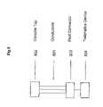
- FIG. 8is a schematic drawing of an alternate embodiment of the wiring harness of FIG. 1 featuring a “vampire tap” for making an electrical connection between the host vehicle's OBD system and the telematics device.
- FIG. 9is a schematic drawing of an alternate embodiment of the wiring harness of FIG. 1 featuring a wireless interface between the host vehicle's OBD system and the telematics device.
- the wiring harnesscomprises a snap-on, configurable adaptor that snaps or is otherwise coupled onto a connector core. Once attached, the pieces form an ‘effective OBD connector’.
- the wiring harnessmay be arranged to enable the telematics device to be effectively hidden under the dashboard while at the same time providing easy access to an OBD connector to obtain diagnostic information from the vehicle's ECU. It may be advantageous for the wiring harness to include a snap-on adaptor because, while the core and pin-out of each OBD connector is universal and mandated by the EPA, the form factors of these connectors typically vary by vehicle make and model.
- a technicianremoves the vehicle's original OBD connector from its location under the dash and connects it to a second connector portion of the harness.
- the technicianthen snaps or otherwise couples an effective OBD connector adaptor with the same form factor as the original OBD connector onto a first connector portion of the harness, and inserts the adaptor into the now-vacated original location of the original OBD connector.
- the technicianmay then secure the telematics device in a location within the vehicle that is not easily accessible or noticeable, and also connects the telematics device to a third connector portion of the harness.
- the technicianmay then deploy the antennae for the GPS and wireless transmitter of the telematics device. Data from the ECU can then be accessed through the original OBD connector, at the second connector portion, through the harness from the effective OBD connector adaptor at the first connector portion, or through the harness by the telematics device from the third connector portion.
- both the effective OBD connector(now located under the dash in the original location of the original OBD connector) and the original OBD connector (now communicating with the telematics device through the harness) communicate serially with the host vehicle's ECU.
- the vehicle's telematics deviceallows the vehicle's telematics device to both communicate with the vehicle's ECU and be hidden from view. This means the device is not visible to passengers within the vehicle, making it unobtrusive and effective for applications such as recovery of stolen vehicles.
- the effective OBD connector adaptorwhich is visible from within the vehicle, looks like the original OBD connector and therefore does not indicate that any telematics device is installed. This too aids recovery of stolen vehicles.
- a techniciancan access the vehicle's diagnostic computer using an automotive scan tool without having to unplug the telematics device from the vehicle's original OBD connector.
- the techniciansimply plugs a scan tool into the effective OBD connector, which is easily accessed underneath the vehicle's dash, and then downloads diagnostic data from the vehicle's ECU.
- a techniciancan use the present invention as a universal wiring harness to install the telematics device in virtually any vehicle. This means it is not necessary to manufacture custom wiring harnesses for each type of vehicle. Companies installing the telematics device (e.g., automotive dealerships) can stock a single ‘base’ wiring harness (which can be relatively expensive) and multiple adaptors (which are relatively inexpensive). This is efficient for control of inventory. Alternatively, through a retail channel, a customer can purchase the telematics device, the base wiring harness, and multiple adaptors.
- the installersimply selects an adaptor that matches the host vehicle's OBD connector, and snaps it or otherwise fastens it to the connector core to form the effective OBD connector. The installer then attaches the effective OBD connector to the wiring harness, installs the telematics device, and may choose to discard the un-used adaptors.
- various embodiments of this systemprovide wireless, real-time transmission and analysis of diagnostic and location-based data, followed by analysis and display of these data by an Internet-accessible website. This makes it possible to characterize the vehicle's performance and determine its location in real-time from virtually any location that has Internet access.
- Diagnostic and location-based datamay be complementary and, when analyzed together, can improve conventional services such as roadside assistance, vehicle-theft notification and recovery, and remote diagnostics.
- the informationcan indicate a vehicle's location, its fuel level and battery voltage, and/or whether or not it has any active DTCs.
- a call centercan dispatch a tow truck with the appropriate materials (e.g., extra gasoline or tools required to repair a specific problem) to repair the vehicle accordingly.
- appropriate materialse.g., extra gasoline or tools required to repair a specific problem
- More applications of conventional telematics systemsare found within the following U.S. Patents, the disclosures of which are herein incorporated by reference: 1) U.S. Pat. No. 6,594,579; 2) U.S. Pat. No. 6,604,033; 3) U.S. Pat. No. 6,611,740; and 4) U.S. Pat. No. 6,636,790.
- one embodiment of the inventionprovides a wiring harness that connects a telematics device to a host vehicle.
- the wiring harnessmay include: 1) a cable featuring a plurality of wires; 2) a first connector featuring a snap-on adaptor that attaches to a connector core with a pin configuration that mates with a diagnostic scan tool; 3) a second connector that connects to an in-vehicle diagnostic system; and 4) a third connector that connects to the telematics device.
- the cableincludes a first connector portion that mates to the first connector, and a second connector portion that mates with the second connector.
- the first and second connector portionscan be IDC connectors.
- the first connectorfurther includes a first set of metal contacts that mate with a diagnostic scan tool, and a second set of metal contacts that mate with the first connector portion.
- the connector coreincludes sixteen metallized cavities and may be configured to mate with an OBD-II male connector.
- the second connectormay include sixteen metallized pins and be configured to mate with an OBD-II female connector.
- other cavity and pin arrangementscould conceivably be employed depending upon the specific application.
- Various embodiments of the present inventionmay be useful in a wide range of vehicles.
- vehiclesinclude, but are not limited to, automobiles, commercial equipment, light, medium and heavy-duty trucks, construction vehicles (e.g., front-end loaders, bulldozers, forklifts), powered sport vehicles (e.g., motorboats, motorcycles, all-terrain vehicles, snowmobiles, jet skis, and other powered sport vehicles), collision repair vehicles, marine vehicles, and recreational vehicles.
- FIG. 1shows a wiring harness 10 according to one embodiment of the invention that features a snap-on adaptor 25 a chosen to match a form factor of the OBD connector present in a host vehicle.
- the snap-on adaptor 25 aconnects to an outer perimeter of an OBD-compliant connector core 26 to form an ‘effective’ OBD connector 27 that looks virtually identical to the OBD connector 36 present in the vehicle.
- the effective OBD connector 27is two-sided: one side includes a core 26 with sixteen OBD-compliant metallized cavities and a configuration that matches a standard OBD connector, while the second side features twenty pins (not shown in the figure) in a configuration that matches a standard IDC connector.
- a printed circuit board(not shown in the figure, but described in more detail with reference to FIG. 2 ) connects each cavity of the connector core 26 to a mating pin in the IDC connector. This may be accomplished during manufacturing.
- the effective OBD connector 27connects to a first connector portion 18 attached to the wiring harness 10 .
- the first connector portion 18is a female, twenty-cavity IDC connector.
- a first clip 23may be used to secure the effective OBD connector 27 to the first connector portion 18 .
- the clip 23is fabricated from metal material. Other materials and arrangements could also be employed for the clip.
- the OBD connector 27could conceivably be attached to the first connector portion 18 by other suitable fasteners and fastening arrangements such as screws or the like.
- the wiring harness 10is also attached to a second connector portion 17 , which, in this embodiment, is identical in configuration to the first connector portion 18 .
- the second connector portion 17in this embodiment features a female twenty-cavity IDC connector. It mates with an OBD connector 28 that, in this embodiment, includes twenty male pins in an IDC pin-out on one side, and sixteen male pins in an OBD pin-out on the other side.
- a third connector portion 16which, in this embodiment, is identical to the above-described first 18 and second 17 connector portions, connects to the in-vehicle telematics device 20 through twenty male pins in an IDC pin-out 24 .
- clips 21 and 22may be fabricated from metal, although other clip materials and/or fastener arrangements could also be successfully employed.
- a twenty-wire ribbon cable 15which may include first 15 A and second 15 B portions, connects individual pins and provides electrical communication between the first 18 , second 17 , and third 16 connector portions.
- the wiring harnessis fully operational and ready to install in the host vehicle.
- the vehicle's original female OBD connector 36is removed from its location and connected to the male OBD connector 28 . See FIG. 6 herein. Once secured, this connection facilitates transmission of power, ground, and the vehicle's diagnostic data, through a serial connection to the host vehicle's ECU and to the telematics device 20 .
- the installermay then insert the effective OBD connector 27 into the vacated slot or mounting area that previously housed or otherwise supported the vehicle's original OBD connector 36 .
- a conventional automotive scan tool 70once plugged into the effective OBD connector 27 , can also download diagnostic information from the vehicle's ECU.
- the third connector portion 16is coupled to the telematics device 20 and the telematics device 20 and cable are secured underneath the vehicle's dash and hidden from view. If the telematics device 20 includes external antennae (e.g. for a wireless transmitter and GPS), these too are secured within the vehicle.
- external antennaee.g. for a wireless transmitter and GPS
- the telematics device 20is not visible to passengers within the vehicle 12 , making it unobtrusive and effective for applications such as recovery of stolen vehicles.
- the effective OBD connector 27looks like the original OBD connector 36 , and is in the original location of the original OBD connector 36 , so it is not obvious that any telematics device 20 has been installed. This further aids in recovering stolen vehicles.
- a techniciancan access the vehicle's diagnostic computer with an automotive scan tool 70 , communicating through the effective OBD connector 27 , without having to unplug the telematics device 20 from the original OBD connector 36 . The technician simply plugs a scan tool 70 into the effective OBD connector 27 , which is easily accessed underneath the vehicle's dash, and then downloads diagnostic data from the vehicle's ECU 35 .
- diagnostic data generated by the vehicle's ECUcan only pass through the effective OBD connector or to the in-vehicle telematics device 20 . It cannot be accessed simultaneously from both components.
- the in-vehicle telematics device 20therefore, typically includes firmware that detects when a scan tool 70 is connected to the effective OBD connector 27 . It then backs off from the ECU so that it receives no data until the scan tool 70 is disconnected. In this way, the technician can download the vehicle's diagnostic data during a repair without having to disconnect the in-vehicle telematics device.
- FIG. 2shows a detailed, exploded view of an embodiment of an effective OBD connector 27 , and provides one example of how this component may be connected to the first connector portion 18 of the cable 15 .
- the effective OBD connector 27 in this embodimentfeatures a snap-on adaptor 25 e that replicates a configuration of the host vehicle's OBD connector 36 ; the adaptor in FIG. 2 , for example, is common for many Toyota, Hyundai, and Chrysler vehicles. However, other adaptor configurations could be employed.
- the adaptor 25 eattaches to an outer perimeter of the connector core 26 .
- a plastic core 29 located within the connector core 26may have sixteen cavities 34 , each filled with a single hollow metal pin 31 a , 31 b .
- the metal pins 31 a , 31 bextend through individual cavities 34 in the plastic core 29 and into a set of corresponding holes 37 formed through a printed circuit board 30 . Once inserted, the ends of the hollow metal pins 31 a , 31 b define a plurality of metallized cavities for accepting a corresponding number and arrangement of metal pins.
- metal traces 32 ′ etched on the printed circuit board 30connect the set of holes 37 to a set of metal leads 38 on the board's opposite side.
- the set of metal leads 38align with a set of pins 39 within an IDC connector 33 .
- the set of pins 39extend through the IDC connector and are exposed on its opposite side 40 .
- the metal pins 31 a , 31 b within the plastic core 29are soldered to the corresponding holes 37 on one side of the printed circuit board 30 .
- Metal leads 38 on the other sideare then press-fit onto the set of pins 39 protruding from the IDC connector 33 .
- This forms the core connector 26which features a set of pins 40 extending from the IDC connector 33 that are in electrical contact with the cavities 34 within the plastic core 29 .
- Other pin and connector arrangementscould conceivably be employed without departing from the spirit and scope of the present invention.
- each adaptor 25 efeatures an opening 41 that matches the geometry of the plastic core's perimeter.
- each adaptor 25 eincludes a circular opening 43 on each side that matches a plastic boss 42 present on each side of the plastic core 26 .
- the installerthen inserts the set of pins 40 extending from the opposite side of the connector core 26 into a set of cavities 44 within the first connector portion 18 connected to the cable 15 of the wiring harness.
- the cable 15 in this embodimentincludes twenty wires. However, other types of cables may also be employed. After this, each cavity 34 in the plastic core 26 is in electrical contact with a corresponding wire within the cable 15 .
- corresponding wires within the cable 15are subsequently in electrical contact with: 1) a unique cavity on the effective OBD connector 27 (present underneath the vehicle's dash); 2) a corresponding cavity in the vehicle's original OBD connector (connected to the male OBD connector 28 of the wiring harness 10 ); and 3) to a corresponding pin on the telematics device (described in more detail below).
- the telematics device 20can receive power and diagnostic data from basically any host vehicle 12 , and then transmit this information through a wireless network to an Internet-accessible website as will be discussed in further detail below.
- the printed circuit board 30includes a set of three metallized holes 32 that are insulated from any pins in the plastic core 29 , but, following installation, are in electrical contact with a microprocessor in the telematics device 20 .
- the microprocessorgenerates data indicating the status of the telematics device 20 .
- the microprocessorcan also accept new firmware.
- a special diagnostic toolplugs into the set of three metallized holes 32 and serially communicates with the microprocessor to either collect data or download new firmware into the device.
- FIG. 3illustrates in more detail the different configurations of snap-on adaptors 25 that can be used with the wiring harness 10 and telematics device 20 according to one embodiment of the invention.
- each adaptorincludes a common opening ( 41 in FIG. 2 ) and circular opening ( 43 in FIG. 3 ), but otherwise has a unique form factor.
- the form factorsmay vary considerably; each is chosen to match that of an OBD connector present in a given vehicle.
- a single snap-on adaptor 25 i selected from the set of different adaptors 25connects to the connector core 26 as described above to complete the wiring harness 10 .
- the wiring harness 10then connects the telematics device 20 to the vehicle as described above.
- Table 1, belowcorrelates individual adaptors 25 a - h within the set of snap-on adaptors 25 to their corresponding vehicle.
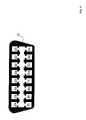
- FIG. 4illustrates each of the sixteen cavities 27 a - p within the effective OBD connector 27 of this embodiment.
- the cavitiesmay supply power ( ⁇ 12V), ground, and a serial interface to one of five serial vehicle-communication protocols currently supported by the host vehicle and described above. Through these protocols the connector 27 receives data from the vehicle's ECU that characterize the on-board electrical, mechanical, and emissions systems.
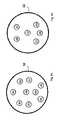
- a version of the wiring harness described abovecan also be used for heavy-duty trucks. These vehicles are typically not OBD-compliant, and support serial communication protocols (referred to herein as J1708/J1587 and CAN) that are different than those described above for light-duty vehicles. Like light-duty vehicles, however, these serial communication protocols collect diagnostic data, generated from a in-vehicle network of sensors, from the host vehicle's ECU. These data are typically made available through a circular six or nine-pin connector typically located in the truck's interior. Unlike light-duty vehicles, the form factors of these connectors typically do not vary in a vehicle-by-vehicle manner.
- FIGS. 5A and 5Bshow, respectively, cross-sections of the nine-pin 50 and six-pin 42 connectors, and the cavities 42 a - e , 50 a - i within these connectors. Examples of typical pin-outs for the effective connectors for these configurations are described in more detail in Tables 3 and 4, below:
- FIG. 6shows a schematic drawing of a telematics system 52 that uses embodiments of the above-described telematics device 20 and wiring harness 10 to monitor diagnostic and location-based information from a host vehicle 12 .
- the telematics device 20connects to the wiring harness 10 through a third connector portion 16 , and the resulting system is installed in a host vehicle 12 as described above.
- the wiring harness 10includes a cable 15 that, on one end, features an effective OBD connector 27 that is located under the vehicle's dash 14 .
- This effective OBD connector 27may populate a slot or other mounting arrangement left behind by the vehicle's original OBD connector 36 , which is removed from its original location during installation and connected to a male sixteen-pin connector 28 attached to the wiring harness 10 .
- the vehicle's original connector 36provides a serial interface to the vehicle's ECU 35 .
- the telematics device 20retrieves diagnostic data collected from the host vehicle 12 , and location-based data from a GPS that collects signals from a constellation 60 of overlying satellites through an airlink 62 .
- the device 20formats these data in separate packets and transmits them over an airlink 59 to a base station 61 included in a wireless network 54 .
- the packetspropagate through the wireless network 54 to a gateway software piece 55 running on a host computer system 57 .
- the host computer system 57processes and stores information from the packets in a database 63 using the gateway software piece 55 .
- the host computer system 57additionally hosts a web site 66 that, once accessed, displays the information.
- a usere.g. an individual working for a call center accesses the web site 66 with a secondary computer system 69 through the Internet 67 .
- the host computer system 57includes a data-processing component 68 that analyzes the location and diagnostic information as described above.
- cables, connectors, and mechanical configurations other than those described abovecan be used for the wiring harness.
- the harnesscan have a ‘Y’ configuration where the effective OBD connector, male OBD connector, and third connector portion are, respectively, at different ends of the ‘Y’.
- the telematics devicecan include a pass-through connector so that the device can receive diagnostic data while making the vehicle's OBD connector available to a scan tool during, for example, repairs.
- the telematics device‘backs off’ the ECU (i.e., the telematics device temporarily stops accessing data from the ECU) using either firmware or hardware, so that the scan tool 70 can read the diagnostic data.
- FIG. 7shows an embodiment as a wiring harness arrangement for connecting a telematics device 704 to a host vehicle, comprising: a plurality of first electrical conductors 702 ; a first connector 701 electrically coupled to at least some of the first electrical conductors 702 and being configured to be connected to an in-vehicle diagnostic system; and a second connector 703 electrically coupled to at least one of the first electrical conductors 702 and configured to be coupled to the telematics device 704 ; a plurality of second electrical conductors 705 , configured to be connected to the telematics device 704 ; and a third electrical connector 706 electrically coupled to at least some of the second electrical conductors 705 and being configured to be coupled to a diagnostic scan tool.
- the wiring harnesscan include ‘vampire taps’ that connect directly to wires within the vehicle's OBD system.
- the original OBD connector within the vehicleis not removed, and the wiring harness therefore lacks an effective OBD connector.
- the appropriate wires from the OBD systeme.g., wires providing high and low serial communication
- wiresare located and connected to corresponding wires within the wiring harness using the taps. These wires connect directly to the telematics device, and supply diagnostic data that is processed as described above. This embodiment, shown in FIG.
- a wiring harness arrangementfor connecting a telematics device 804 to a host vehicle, comprising: a plurality of conductors 801 ; a set of vampire taps 802 electrically coupled to at least some of the electrical conductors 801 and being configured to be connected to an in-vehicle diagnostic system; and a first connector 803 electrically coupled to at least one of the electrical conductors 801 and configured to be coupled to the telematics device 804 .
- short-range wireless devicessuch as BluetoothTM or 802.11-based devices
- BluetoothTM transmittercan be connected to the vehicle's OBD system, and wirelessly transmit diagnostic data to a corresponding BluetoothTM receiver in the telematics device. The telematics device then transmits these data over a nation-wide wireless network using a conventional wireless transmitter. This embodiment shown in FIG.
- a system for connecting a telematics device 904 to a host vehiclecomprising: a short-range wireless transmitter 901 connected to an in-vehicle diagnostic system 902 ; and a short-range wireless receiver 903 connected to the telematics device 904 installed in the host vehicle; wherein the transmitter 901 is configured to wirelessly transmit 905 diagnostic data to the receiver 903 .
- the snap-on adaptors, connector portions, cabling, and pinscan have different configurations than those shown above.
- the telematics system shown in FIG. 6 in vehicle 12may also be implemented in communication with other hardware and software systems different than or in addition to those shown 61 , 54 , 55 , 57 , 63 , 66 , 67 , 52 , 69 , 60 in that figure.
- Such other hardware and software systemsare described, for example, in the following references, the disclosures of which have been previously incorporated herein by reference: 1) U.S. Pat. No. 6,594,579; 2) U.S. Pat. No. 6,604,033; 3) U.S. Pat. Nos. 6,611,740; and 4) U.S. Pat. No. 6,636,790.
- a single componentcan be replaced by multiple components, and multiple components replaced by a single component, to perform a given function or functions. Except where such substitution would not be operative to practice embodiments of the present invention, such substitution is within the scope of the present invention.
Landscapes
- Engineering & Computer Science (AREA)
- Mechanical Engineering (AREA)
- Physics & Mathematics (AREA)
- General Physics & Mathematics (AREA)
- Details Of Connecting Devices For Male And Female Coupling (AREA)
- Mobile Radio Communication Systems (AREA)
- Fittings On The Vehicle Exterior For Carrying Loads, And Devices For Holding Or Mounting Articles (AREA)
Abstract
Description
| TABLE 1 |
| snap-on adaptors and their corresponding host vehicles |
| Host | |
| 25a | Ford |
| 25b | Toyota, Honda, |
| 25c | Toyota, |
| 25d | Saturn, |
| 25e | Mercedes, |
| 25f | Porsche, Audi, |
| 25g | |
| 25h | Saab |
| TABLE 2 |
| cavities within the effective OBD connector and their |
| Cavity | |
| 27b | J1850+ |
| Chassis Ground | ||
| Signal Ground | ||
| CAN High | ||
| 27g | ISO 9141-2 K Line | |
| 27j | J1850− | |
| 27n | CAN Low | |
| 27o | ISO 9141-2 | |
| 27p | Battery Power (~12 V) | |
| TABLE 3 |
| cavities and their function for the effective connector for a |
| heavy-duty truck featuring a nine-pin connector |
| Cavity | Function | |
| Chassis Ground | ||
| 50b | Battery Power (~12 V) | |
| 50c | CAN | |
| 50d | CAN Low | |
| 50e | CAN Shield | |
| 50f | J1708+ | |
| 50g | J1708− | |
| 50h | Proprietary | |
| 50i | Proprietary | |
| TABLE 4 |
| cavities and their function for the effective connector for a |
| heavy-duty truck featuring a six-pin connector |
| Cavity | |
| 42a | J1708+ |
| 42b | J1708− |
| 42c | Battery Power (~12 V) |
| 42d | No Standard Function |
| 42e | Chassis Ground |
| 42f | No Standard Function |
Claims (8)
Priority Applications (1)
| Application Number | Priority Date | Filing Date | Title |
|---|---|---|---|
| US12/261,751US7672763B1 (en) | 2004-04-26 | 2008-10-30 | Method for coupling a telematics device to a vehicle using an in-vehicle wiring harness with multiple adaptors for an on-board diagnostic connector |
Applications Claiming Priority (3)
| Application Number | Priority Date | Filing Date | Title |
|---|---|---|---|
| US10/831,952US7225065B1 (en) | 2004-04-26 | 2004-04-26 | In-vehicle wiring harness with multiple adaptors for an on-board diagnostic connector |
| US11/799,848US7447574B1 (en) | 2004-04-26 | 2007-05-03 | In-vehicle wiring harness with multiple adaptors for an on-board diagnostic connector |
| US12/261,751US7672763B1 (en) | 2004-04-26 | 2008-10-30 | Method for coupling a telematics device to a vehicle using an in-vehicle wiring harness with multiple adaptors for an on-board diagnostic connector |
Related Parent Applications (1)
| Application Number | Title | Priority Date | Filing Date |
|---|---|---|---|
| US11/799,848DivisionUS7447574B1 (en) | 2004-04-26 | 2007-05-03 | In-vehicle wiring harness with multiple adaptors for an on-board diagnostic connector |
Publications (1)
| Publication Number | Publication Date |
|---|---|
| US7672763B1true US7672763B1 (en) | 2010-03-02 |
Family
ID=38056832
Family Applications (6)
| Application Number | Title | Priority Date | Filing Date |
|---|---|---|---|
| US10/831,952Expired - LifetimeUS7225065B1 (en) | 2004-04-26 | 2004-04-26 | In-vehicle wiring harness with multiple adaptors for an on-board diagnostic connector |
| US11/799,848Expired - Fee RelatedUS7447574B1 (en) | 2004-04-26 | 2007-05-03 | In-vehicle wiring harness with multiple adaptors for an on-board diagnostic connector |
| US12/261,751Expired - LifetimeUS7672763B1 (en) | 2004-04-26 | 2008-10-30 | Method for coupling a telematics device to a vehicle using an in-vehicle wiring harness with multiple adaptors for an on-board diagnostic connector |
| US12/261,735Expired - Fee RelatedUS7596437B1 (en) | 2004-04-26 | 2008-10-30 | Method for mounting a telematics device within a vehicle using an in vehicle wiring harness with multiple adaptors for an on-board diagnostic connector |
| US12/261,719Expired - Fee RelatedUS7778752B1 (en) | 2004-04-26 | 2008-10-30 | System for connecting a telematics device to a vehicle using a wireless receiver configured to transmit diagnostic data |
| US12/833,242AbandonedUS20110166742A1 (en) | 2004-04-26 | 2010-07-09 | Method and system for connecting a telematics device to a vehicle using wireless transceivers configured to transmit and receive diagnostic data |
Family Applications Before (2)
| Application Number | Title | Priority Date | Filing Date |
|---|---|---|---|
| US10/831,952Expired - LifetimeUS7225065B1 (en) | 2004-04-26 | 2004-04-26 | In-vehicle wiring harness with multiple adaptors for an on-board diagnostic connector |
| US11/799,848Expired - Fee RelatedUS7447574B1 (en) | 2004-04-26 | 2007-05-03 | In-vehicle wiring harness with multiple adaptors for an on-board diagnostic connector |
Family Applications After (3)
| Application Number | Title | Priority Date | Filing Date |
|---|---|---|---|
| US12/261,735Expired - Fee RelatedUS7596437B1 (en) | 2004-04-26 | 2008-10-30 | Method for mounting a telematics device within a vehicle using an in vehicle wiring harness with multiple adaptors for an on-board diagnostic connector |
| US12/261,719Expired - Fee RelatedUS7778752B1 (en) | 2004-04-26 | 2008-10-30 | System for connecting a telematics device to a vehicle using a wireless receiver configured to transmit diagnostic data |
| US12/833,242AbandonedUS20110166742A1 (en) | 2004-04-26 | 2010-07-09 | Method and system for connecting a telematics device to a vehicle using wireless transceivers configured to transmit and receive diagnostic data |
Country Status (1)
| Country | Link |
|---|---|
| US (6) | US7225065B1 (en) |
Cited By (25)
| Publication number | Priority date | Publication date | Assignee | Title |
|---|---|---|---|---|
| US20080268662A1 (en)* | 2007-04-26 | 2008-10-30 | Krivtsov Sergey M | Pass-through connector |
| US20090237245A1 (en)* | 2001-09-11 | 2009-09-24 | Zonar Systems, Inc. | Method and apparatus to automate data collection during a mandatory inpsection |
| US20090256693A1 (en)* | 2001-09-11 | 2009-10-15 | Zonar Systems, Inc. | System and process to validate inspection data |
| US20100185479A1 (en)* | 2006-06-20 | 2010-07-22 | Zonar Systems, Inc. | Method and apparatus to analyze gps data to determine if a vehicle has adhered to a predetermined route |
| US20100280734A1 (en)* | 2006-06-20 | 2010-11-04 | Zonar Systems, Inc. | Method and apparatus to encode fuel use data with gps data and to analyze such data |
| US20110022248A1 (en)* | 2001-09-11 | 2011-01-27 | Zonar Systems, Inc. | System and method to improve the efficiency of vehicle inspections by enabling remote actuation of vehicle components |
| US20110068954A1 (en)* | 2006-06-20 | 2011-03-24 | Zonar Systems, Inc. | Method and apparatus to collect object identification data during operation of a vehicle and analysis of such data |
| US20110098879A1 (en)* | 2009-10-23 | 2011-04-28 | Basir Otman A | Hardware reconfigurable vehicle on-board diagnostic interface and telematic system |
| US20110112932A1 (en)* | 2009-11-10 | 2011-05-12 | Ieon Chen | Method and Apparatus for Interfacing an Automotive Diagnostic Tool with a Diagnostic Database |
| US8736419B2 (en) | 2010-12-02 | 2014-05-27 | Zonar Systems | Method and apparatus for implementing a vehicle inspection waiver program |
| US20140277917A1 (en)* | 2003-07-24 | 2014-09-18 | Matthew Banet | Wireless vehicle-monitoring system |
| US8856536B2 (en) | 2011-12-15 | 2014-10-07 | GM Global Technology Operations LLC | Method and apparatus for secure firmware download using diagnostic link connector (DLC) and OnStar system |
| US8966248B2 (en) | 2012-04-06 | 2015-02-24 | GM Global Technology Operations LLC | Secure software file transfer systems and methods for vehicle control modules |
| US20170011561A1 (en)* | 2015-07-09 | 2017-01-12 | Ford Global Technologies, Llc | Connected services for vehicle diagnostics and repairs |
| US9635518B2 (en) | 2014-09-29 | 2017-04-25 | Avis Budget Car Rental, LLC | Telematics system, methods and apparatus for two-way data communication between vehicles in a fleet and a fleet management system |
| US10056008B1 (en) | 2006-06-20 | 2018-08-21 | Zonar Systems, Inc. | Using telematics data including position data and vehicle analytics to train drivers to improve efficiency of vehicle use |
| US10289651B2 (en) | 2012-04-01 | 2019-05-14 | Zonar Systems, Inc. | Method and apparatus for matching vehicle ECU programming to current vehicle operating conditions |
| US10431020B2 (en) | 2010-12-02 | 2019-10-01 | Zonar Systems, Inc. | Method and apparatus for implementing a vehicle inspection waiver program |
| US10431097B2 (en) | 2011-06-13 | 2019-10-01 | Zonar Systems, Inc. | System and method to enhance the utility of vehicle inspection records by including route identification data in each vehicle inspection record |
| US10600096B2 (en) | 2010-11-30 | 2020-03-24 | Zonar Systems, Inc. | System and method for obtaining competitive pricing for vehicle services |
| US10656280B2 (en) | 2014-05-13 | 2020-05-19 | Key Control Holding, Inc. | Vehicle monitoring systems and methods |
| US10665040B2 (en) | 2010-08-27 | 2020-05-26 | Zonar Systems, Inc. | Method and apparatus for remote vehicle diagnosis |
| US10706647B2 (en) | 2010-12-02 | 2020-07-07 | Zonar Systems, Inc. | Method and apparatus for implementing a vehicle inspection waiver program |
| US11341853B2 (en) | 2001-09-11 | 2022-05-24 | Zonar Systems, Inc. | System and method to enhance the utility of vehicle inspection records by including route identification data in each vehicle inspection record |
| US12125082B2 (en) | 2010-11-30 | 2024-10-22 | Zonar Systems, Inc. | System and method for obtaining competitive pricing for vehicle services |
Families Citing this family (127)
| Publication number | Priority date | Publication date | Assignee | Title |
|---|---|---|---|---|
| US7904219B1 (en) | 2000-07-25 | 2011-03-08 | Htiip, Llc | Peripheral access devices and sensors for use with vehicle telematics devices and systems |
| US20020173885A1 (en) | 2001-03-13 | 2002-11-21 | Lowrey Larkin Hill | Internet-based system for monitoring vehicles |
| US6611740B2 (en) | 2001-03-14 | 2003-08-26 | Networkcar | Internet-based vehicle-diagnostic system |
| US7113127B1 (en)* | 2003-07-24 | 2006-09-26 | Reynolds And Reynolds Holdings, Inc. | Wireless vehicle-monitoring system operating on both terrestrial and satellite networks |
| US7225065B1 (en) | 2004-04-26 | 2007-05-29 | Hti Ip, Llc | In-vehicle wiring harness with multiple adaptors for an on-board diagnostic connector |
| KR100828291B1 (en)* | 2004-12-07 | 2008-05-07 | 주식회사 현대오토넷 | Theft Report System and Method Using Telematics System |
| US8559937B2 (en)* | 2005-06-07 | 2013-10-15 | Qualcomm Incorporated | Wireless system for providing critical sensor alerts for equipment |
| US20100010705A1 (en)* | 2005-10-20 | 2010-01-14 | Airmax Group Plc | Methods and apparatus for monitoring vehicle data |
| GB0521323D0 (en)* | 2005-10-20 | 2005-11-30 | Airmax Group Plc | Methods and apparatus for monitoring vehicle data |
| US7859392B2 (en) | 2006-05-22 | 2010-12-28 | Iwi, Inc. | System and method for monitoring and updating speed-by-street data |
| US9067565B2 (en) | 2006-05-22 | 2015-06-30 | Inthinc Technology Solutions, Inc. | System and method for evaluating driver behavior |
| US7689594B2 (en)* | 2006-09-22 | 2010-03-30 | The Boeing Company | Vehicle management and mission management computer architecture and packaging |
| US7899610B2 (en) | 2006-10-02 | 2011-03-01 | Inthinc Technology Solutions, Inc. | System and method for reconfiguring an electronic control unit of a motor vehicle to optimize fuel economy |
| JP4270258B2 (en)* | 2006-10-02 | 2009-05-27 | セイコーエプソン株式会社 | Droplet discharge head, droplet discharge device, method for manufacturing droplet discharge head, and method for manufacturing droplet discharge device |
| US7808371B2 (en) | 2006-10-03 | 2010-10-05 | 2862-8030 Quebec Inc. | Vehicle fleet security system |
| US20080086246A1 (en)* | 2006-10-04 | 2008-04-10 | Scott Bolt | Portable vehicle powering and testing systems |
| US9208627B2 (en)* | 2007-02-12 | 2015-12-08 | Bosch Automotive Service Solutions Inc. | Scan tool with integrated global positioning system |
| DE102007018830A1 (en)* | 2007-04-20 | 2008-12-24 | Continental Automotive Gmbh | Arrangement for data transmission |
| WO2008151103A1 (en)* | 2007-05-31 | 2008-12-11 | Hti Ip, Llc | Methods, systems, and apparatuses for consumer telematics |
| US8825277B2 (en) | 2007-06-05 | 2014-09-02 | Inthinc Technology Solutions, Inc. | System and method for the collection, correlation and use of vehicle collision data |
| US8666590B2 (en) | 2007-06-22 | 2014-03-04 | Inthinc Technology Solutions, Inc. | System and method for naming, filtering, and recall of remotely monitored event data |
| US9129460B2 (en) | 2007-06-25 | 2015-09-08 | Inthinc Technology Solutions, Inc. | System and method for monitoring and improving driver behavior |
| US7999670B2 (en) | 2007-07-02 | 2011-08-16 | Inthinc Technology Solutions, Inc. | System and method for defining areas of interest and modifying asset monitoring in relation thereto |
| US9235938B2 (en)* | 2007-07-12 | 2016-01-12 | Omnitracs, Llc | Apparatus and method for measuring operational data for equipment using sensor breach durations |
| US9117246B2 (en) | 2007-07-17 | 2015-08-25 | Inthinc Technology Solutions, Inc. | System and method for providing a user interface for vehicle mentoring system users and insurers |
| US8818618B2 (en) | 2007-07-17 | 2014-08-26 | Inthinc Technology Solutions, Inc. | System and method for providing a user interface for vehicle monitoring system users and insurers |
| US8577703B2 (en) | 2007-07-17 | 2013-11-05 | Inthinc Technology Solutions, Inc. | System and method for categorizing driving behavior using driver mentoring and/or monitoring equipment to determine an underwriting risk |
| US7876205B2 (en) | 2007-10-02 | 2011-01-25 | Inthinc Technology Solutions, Inc. | System and method for detecting use of a wireless device in a moving vehicle |
| US20090222338A1 (en)* | 2008-03-03 | 2009-09-03 | Hamilton Ii Rick A | Monitoring and Rewards Methodologies for "Green" Use of Vehicles |
| CN102150278A (en)* | 2008-06-11 | 2011-08-10 | 因特瓦克公司 | Formation of solar cell-selective emitter using implant and anneal method |
| US7881887B2 (en)* | 2008-07-14 | 2011-02-01 | Sikorsky Aircraft Corporation | Wireless wireharness testing system |
| US20100023198A1 (en)* | 2008-07-24 | 2010-01-28 | Brennan Todd Hamilton | System and method for emulating vehicle ignition-switched power |
| US8688180B2 (en) | 2008-08-06 | 2014-04-01 | Inthinc Technology Solutions, Inc. | System and method for detecting use of a wireless device while driving |
| CN102203810A (en) | 2008-09-09 | 2011-09-28 | 美国联合包裹服务公司 | Systems and methods of utilizing telematics data to improve fleet management operations |
| US11482058B2 (en) | 2008-09-09 | 2022-10-25 | United Parcel Service Of America, Inc. | Systems and methods for utilizing telematics data to improve fleet management operations |
| USD624502S1 (en) | 2008-10-22 | 2010-09-28 | Honda Motor Co., Ltd. | Connector for use with vehicle functionality testing device |
| US8963702B2 (en) | 2009-02-13 | 2015-02-24 | Inthinc Technology Solutions, Inc. | System and method for viewing and correcting data in a street mapping database |
| US8892341B2 (en) | 2009-02-13 | 2014-11-18 | Inthinc Technology Solutions, Inc. | Driver mentoring to improve vehicle operation |
| US8188887B2 (en) | 2009-02-13 | 2012-05-29 | Inthinc Technology Solutions, Inc. | System and method for alerting drivers to road conditions |
| US8749053B2 (en) | 2009-06-23 | 2014-06-10 | Intevac, Inc. | Plasma grid implant system for use in solar cell fabrications |
| US9589395B2 (en)* | 2009-11-02 | 2017-03-07 | Bosch Automotive Service Solutions Inc. | Tool interface connector wireless adapter compact design |
| US8392764B2 (en)* | 2009-11-16 | 2013-03-05 | Cooper Technologies Company | Methods and systems for identifying and configuring networked devices |
| US8886393B2 (en)* | 2009-12-17 | 2014-11-11 | General Motors Llc | Vehicle telematics communication for providing in-vehicle reminders |
| US9329049B2 (en)* | 2009-12-17 | 2016-05-03 | General Motors Llc | Vehicle telematics communications for providing directions to a vehicle service facility |
| SG183267A1 (en)* | 2010-02-09 | 2012-09-27 | Intevac Inc | An adjustable shadow mask assembly for use in solar cell fabrications |
| US8903597B2 (en)* | 2010-04-30 | 2014-12-02 | Cability, Inc. | Multipurpose in-vehicle diagnostic II adapter |
| US10046649B2 (en)* | 2012-06-28 | 2018-08-14 | Midtronics, Inc. | Hybrid and electric vehicle battery pack maintenance device |
| US20110300416A1 (en) | 2010-06-03 | 2011-12-08 | Bertness Kevin I | Battery pack maintenance for electric vehicle |
| US11740294B2 (en) | 2010-06-03 | 2023-08-29 | Midtronics, Inc. | High use battery pack maintenance |
| GB2483868B (en)* | 2010-09-21 | 2015-08-26 | Lysanda Ltd | Vehicle diagnostics port adaptor |
| US8688313B2 (en)* | 2010-12-23 | 2014-04-01 | Aes Technologies, Llc. | Remote vehicle programming system and method |
| US8928495B2 (en) | 2011-01-24 | 2015-01-06 | Lexisnexis Risk Solutions Inc. | Systems and methods for telematics monitoring and communications |
| US9164957B2 (en) | 2011-01-24 | 2015-10-20 | Lexisnexis Risk Solutions Inc. | Systems and methods for telematics monitoring and communications |
| US9953468B2 (en) | 2011-03-31 | 2018-04-24 | United Parcel Service Of America, Inc. | Segmenting operational data |
| US9208626B2 (en) | 2011-03-31 | 2015-12-08 | United Parcel Service Of America, Inc. | Systems and methods for segmenting operational data |
| US8480433B2 (en)* | 2011-04-05 | 2013-07-09 | Sung Jung Minute Industry Co., Ltd. | On-board diagnostic adapter |
| US20130045677A1 (en)* | 2011-08-17 | 2013-02-21 | Ho-Sung Chien | Telematics System and Related Mobile Device and Method |
| US9177427B1 (en) | 2011-08-24 | 2015-11-03 | Allstate Insurance Company | Vehicle driver feedback device |
| SG11201402177XA (en) | 2011-11-08 | 2014-06-27 | Intevac Inc | Substrate processing system and method |
| US10528913B2 (en) | 2011-12-30 | 2020-01-07 | Elwha Llc | Evidence-based healthcare information management protocols |
| US10340034B2 (en) | 2011-12-30 | 2019-07-02 | Elwha Llc | Evidence-based healthcare information management protocols |
| US10475142B2 (en) | 2011-12-30 | 2019-11-12 | Elwha Llc | Evidence-based healthcare information management protocols |
| US10552581B2 (en) | 2011-12-30 | 2020-02-04 | Elwha Llc | Evidence-based healthcare information management protocols |
| US10679309B2 (en) | 2011-12-30 | 2020-06-09 | Elwha Llc | Evidence-based healthcare information management protocols |
| US10559380B2 (en) | 2011-12-30 | 2020-02-11 | Elwha Llc | Evidence-based healthcare information management protocols |
| US20130173294A1 (en) | 2011-12-30 | 2013-07-04 | Elwha LLC, a limited liability company of the State of Delaware | Evidence-based healthcare information management protocols |
| US10942871B2 (en)* | 2012-04-23 | 2021-03-09 | Geotab Inc. | Intelligent bluetooth beacon I/O expansion system |
| DE102012210437A1 (en)* | 2012-06-20 | 2013-12-24 | Robert Bosch Gmbh | Contact configuration |
| US11325479B2 (en)* | 2012-06-28 | 2022-05-10 | Midtronics, Inc. | Hybrid and electric vehicle battery maintenance device |
| MY178951A (en) | 2012-12-19 | 2020-10-23 | Intevac Inc | Grid for plasma ion implant |
| US10240548B2 (en)* | 2013-07-23 | 2019-03-26 | Nxp Usa, Inc. | Control system and method of operating a control system |
| US9240082B2 (en) | 2013-10-22 | 2016-01-19 | At&T Intellectual Property I, L.P. | Crowd sourced optimization of vehicle performance based on cloud based data |
| US9172477B2 (en) | 2013-10-30 | 2015-10-27 | Inthinc Technology Solutions, Inc. | Wireless device detection using multiple antennas separated by an RF shield |
| US9805521B1 (en) | 2013-12-03 | 2017-10-31 | United Parcel Service Of America, Inc. | Systems and methods for assessing turns made by a vehicle |
| ITTV20140011U1 (en) | 2014-03-13 | 2015-09-13 | Texa Spa | DIAGNOSTIC INTERFACE MODULE FOR VEHICLES |
| US10001087B2 (en)* | 2014-03-19 | 2018-06-19 | Anthony Stephen Hanak | EGR power module and method of use thereof |
| US10151280B2 (en)* | 2014-03-19 | 2018-12-11 | Anthony Stephen Hanak | EGR power module and method of use thereof |
| US20160334225A1 (en) | 2015-05-11 | 2016-11-17 | United Parcel Service Of America, Inc. | Determining street segment headings |
| CA2988921C (en)* | 2015-06-19 | 2024-02-13 | Bombardier Inc. | Configurable harness |
| US10614640B2 (en) | 2015-08-05 | 2020-04-07 | EZ Lynk SEZC | System and method for real time wireless ECU monitoring and reprogramming |
| US11210871B2 (en) | 2015-08-05 | 2021-12-28 | EZ Lynk SEZC | System and method for remote emissions control unit monitoring and reprogramming |
| US10621796B2 (en) | 2015-08-05 | 2020-04-14 | EZ Lynk SEZC | System and method for real time wireless ECU monitoring and reprogramming |
| US11430273B2 (en) | 2015-08-05 | 2022-08-30 | EZ Lynk SEZC | Apparatus and method for remote ELD monitoring and ECU reprogramming |
| US10347055B2 (en)* | 2015-09-28 | 2019-07-09 | Noregon Systems, Inc. | Method and apparatus for connecting to a heavy duty vehicle and performing a vehicle roadworthiness check |
| US10033130B2 (en) | 2015-12-01 | 2018-07-24 | Geotab Inc. | Substitute flange sleeve for alternative mounting of a cylindrical heavy duty deutsch type on-board diagnostic receptacle |
| AU2016377735B2 (en)* | 2015-12-24 | 2019-10-17 | Beijing Didi Infinity Technology And Development Co., Ltd. | Systems and methods for vehicle management |
| FR3046883B1 (en)* | 2016-01-20 | 2019-06-14 | Eliocity | DEVICE FOR CONNECTING AN ELECTRONIC HOUSING TO A VEHICULAR BEAM, SYSTEM AND METHOD THEREOF |
| US20170309085A1 (en)* | 2016-04-22 | 2017-10-26 | Verizon Patent And Licensing Inc. | Providing vehicle information to a telematics device via an expansion device |
| IT201600099421A1 (en)* | 2016-10-04 | 2018-04-04 | Texa Spa | DIAGNOSTIC DEVICE ON BOARD FOR VEHICLES |
| US12320857B2 (en) | 2016-10-25 | 2025-06-03 | Midtronics, Inc. | Electrical load for electronic battery tester and electronic battery tester including such electrical load |
| US20210133808A1 (en) | 2016-10-28 | 2021-05-06 | State Farm Mutual Automobile Insurance Company | Vehicle identification using driver profiles |
| USD833896S1 (en)* | 2017-02-14 | 2018-11-20 | Tomtom Telematics B.V. | Telematics device |
| US10467828B2 (en) | 2017-03-06 | 2019-11-05 | J. J. Keller & Associates, Inc. | Electronic logging device |
| FR3063946A1 (en)* | 2017-03-15 | 2018-09-21 | Tally Fofana | AUTOMOTIVE ANTI-THEFT CANCELING THE ORIGINAL OBD PORT REPLACING IT WITH A PORTABLE OBD PORT COMPRISING 1 OBD TRANSMITTER COMMUNICATING WITH 1 OBD RECEIVER VIA 1 SECURE APPLICATION. |
| US10085137B1 (en) | 2017-03-22 | 2018-09-25 | Cnh Industrial America Llc | Method and system for sharing a telematics access point |
| US10109959B1 (en)* | 2017-05-25 | 2018-10-23 | Juniper Networks, Inc. | Electrical connector with embedded processor |
| US10412094B2 (en)* | 2017-05-25 | 2019-09-10 | GM Global Technology Operations LLC | Privileged, diagnostic link connector based network monitoring capabilities within a vehicle employing a gateway module used to isolate and secure vehicle networks |
| JP7094670B2 (en)* | 2017-07-03 | 2022-07-04 | 矢崎総業株式会社 | Setting device and computer |
| USD865640S1 (en)* | 2017-09-01 | 2019-11-05 | Solera Holdings, Inc. | On-board diagnostics module |
| USD865639S1 (en)* | 2017-09-01 | 2019-11-05 | Facebook, Inc. | On-board diagnostics module |
| US10431946B2 (en)* | 2017-10-19 | 2019-10-01 | Joseph P. Zizzadoro | Vehicular security bypass |
| CN119277348A (en) | 2017-10-30 | 2025-01-07 | 卡明斯公司 | Smart Connector Components |
| CN108123835A (en)* | 2017-12-18 | 2018-06-05 | 广州亚美信息科技有限公司 | A kind of the vehicle compatibility method and system of the car networking terminal based on self study |
| US10553993B2 (en) | 2018-04-11 | 2020-02-04 | The Boeing Company | Avionics system interface electrical connector |
| FR3081008B1 (en)* | 2018-05-11 | 2020-06-12 | Yann Goavec | DEVICE FOR SECURING A VEHICLE AGAINST THEFT. |
| USD900653S1 (en)* | 2018-05-16 | 2020-11-03 | Webfleet Solutions B.V. | Telematics device |
| US10601188B2 (en)* | 2018-08-01 | 2020-03-24 | Cnh Industrial America Llc | Jumper harness with LED |
| US11513160B2 (en) | 2018-11-29 | 2022-11-29 | Midtronics, Inc. | Vehicle battery maintenance device |
| EP3687087B1 (en) | 2019-01-28 | 2023-08-02 | Volvo Car Corporation | A telematics verification system |
| FR3094847B1 (en)* | 2019-04-02 | 2021-02-26 | Psa Automobiles Sa | Method of adapting an electrical harness for a land motor vehicle |
| US11613023B2 (en) | 2019-06-07 | 2023-03-28 | Noble Plastics, Inc. | Edge device interface system and method for monitoring and modifying control and response signals transmitted to and from injection-molding machines and robots |
| US11566972B2 (en) | 2019-07-31 | 2023-01-31 | Midtronics, Inc. | Tire tread gauge using visual indicator |
| US11474153B2 (en) | 2019-11-12 | 2022-10-18 | Midtronics, Inc. | Battery pack maintenance system |
| US11973202B2 (en) | 2019-12-31 | 2024-04-30 | Midtronics, Inc. | Intelligent module interface for battery maintenance device |
| DE102020216599A1 (en) | 2019-12-31 | 2021-07-01 | Midtronics, Inc. | Intelligent module interface for a battery maintenance device |
| US11486930B2 (en) | 2020-01-23 | 2022-11-01 | Midtronics, Inc. | Electronic battery tester with battery clamp storage holsters |
| US12211009B2 (en)* | 2020-02-21 | 2025-01-28 | Idsc Holdings Llc | Method and system of providing cloud-based vehicle history session |
| US11574510B2 (en) | 2020-03-30 | 2023-02-07 | Innova Electronics Corporation | Multi-functional automotive diagnostic tablet with interchangeable function-specific cartridges |
| USD951950S1 (en)* | 2020-09-04 | 2022-05-17 | Shenzhen Chebotong Technology Co., Ltd | Car data scanner |
| USD951948S1 (en)* | 2020-09-04 | 2022-05-17 | Shenzhen Chebotong Technology Co., Ltd | Car data scanner |
| USD951949S1 (en)* | 2020-09-04 | 2022-05-17 | Shenzhen Chebotong Technology Co., Ltd | Car data scanner |
| USD951951S1 (en)* | 2020-09-04 | 2022-05-17 | Shenzhen Chebotong Technology Co., Ltd | Car data scanner |
| JP2021079946A (en) | 2021-02-16 | 2021-05-27 | 株式会社ユピテル | Article |
| AU2022333546A1 (en)* | 2021-08-25 | 2024-03-07 | Ame Systems (Vic) Pty Ltd | Method, apparatus and system for electrical connection |
| US12330513B2 (en) | 2022-02-14 | 2025-06-17 | Midtronics, Inc. | Battery maintenance device with high voltage connector |
| US12392833B2 (en) | 2022-05-09 | 2025-08-19 | Midtronics, Inc. | Electronic battery tester |
| US20250282309A1 (en)* | 2024-03-06 | 2025-09-11 | Geotab Inc. | Splitter Harness for Vehicles with a Proprietary Interface Port Connector |
Citations (2)
| Publication number | Priority date | Publication date | Assignee | Title |
|---|---|---|---|---|
| US7225065B1 (en)* | 2004-04-26 | 2007-05-29 | Hti Ip, Llc | In-vehicle wiring harness with multiple adaptors for an on-board diagnostic connector |
| US7599769B2 (en)* | 2004-12-07 | 2009-10-06 | Hyundai Autonet Co., Ltd. | System and method for reporting vehicle theft using telematics system |
Family Cites Families (191)
| Publication number | Priority date | Publication date | Assignee | Title |
|---|---|---|---|---|
| US3748894A (en) | 1972-06-15 | 1973-07-31 | Texaco Inc | Means and method for an on-line determination of the flash point of lube oil fractions |
| US4258421A (en) | 1978-02-27 | 1981-03-24 | Rockwell International Corporation | Vehicle monitoring and recording system |
| US4602127A (en) | 1984-03-09 | 1986-07-22 | Micro Processor Systems, Inc. | Diagnostic data recorder |
| US4694408A (en) | 1986-01-15 | 1987-09-15 | Zaleski James V | Apparatus for testing auto electronics systems |
| US4690475A (en)* | 1986-09-02 | 1987-09-01 | Mcelroy Robert C | Computer harness adaptive tester |
| US5457629A (en) | 1989-01-31 | 1995-10-10 | Norand Corporation | Vehicle data system with common supply of data and power to vehicle devices |
| JPH0752142B2 (en) | 1987-12-21 | 1995-06-05 | 富士重工業株式会社 | Vehicle diagnostic device |
| US4956777A (en) | 1988-06-09 | 1990-09-11 | R. J. Reynolds Tobacco Company | Automatic vehicle control system |
| JPH0776735B2 (en) | 1988-09-28 | 1995-08-16 | 富士重工業株式会社 | Vehicle diagnostic system |
| CA1340400C (en) | 1989-01-31 | 1999-02-16 | Philip Miller | Vehicle data system |
| JP2574892B2 (en) | 1989-02-15 | 1997-01-22 | 株式会社日立製作所 | Load sharing control method for automobile |
| US5003317A (en) | 1989-07-11 | 1991-03-26 | Mets, Inc. | Stolen vehicle recovery system |
| CA1318718C (en) | 1989-09-29 | 1993-06-01 | Wayne G. Wilson | Interactive connector unit for a wiring harness |
| GB9016533D0 (en) | 1990-07-27 | 1990-09-12 | Churchill V L Ltd | Automotive diagnostic tool |
| GB9019423D0 (en) | 1990-09-06 | 1990-10-24 | Gen Motors Luxembourg Operatio | Electronic controller for vehicle |
| US5155689A (en) | 1991-01-17 | 1992-10-13 | By-Word Technologies, Inc. | Vehicle locating and communicating method and apparatus |
| US6738697B2 (en) | 1995-06-07 | 2004-05-18 | Automotive Technologies International Inc. | Telematics system for vehicle diagnostics |
| US5257190A (en) | 1991-08-12 | 1993-10-26 | Crane Harold E | Interactive dynamic realtime management system for powered vehicles |
| US5479479A (en) | 1991-10-19 | 1995-12-26 | Cell Port Labs, Inc. | Method and apparatus for transmission of and receiving signals having digital information using an air link |
| US5539810A (en) | 1992-01-27 | 1996-07-23 | Highwaymaster Communications, Inc. | Data messaging in a communications network |
| US5223844B1 (en) | 1992-04-17 | 2000-01-25 | Auto Trac Inc | Vehicle tracking and security system |
| US5343906A (en) | 1992-05-15 | 1994-09-06 | Biodigital Technologies, Inc. | Emisson validation system |
| US6144916A (en) | 1992-05-15 | 2000-11-07 | Micron Communications, Inc. | Itinerary monitoring system for storing a plurality of itinerary data points |
| US5636122A (en) | 1992-10-16 | 1997-06-03 | Mobile Information Systems, Inc. | Method and apparatus for tracking vehicle location and computer aided dispatch |
| US5758313A (en) | 1992-10-16 | 1998-05-26 | Mobile Information Systems, Inc. | Method and apparatus for tracking vehicle location |
| US20020171650A1 (en) | 1992-10-16 | 2002-11-21 | Mobile Information Systems, Inc. | Apparatus for graphical fleet management |
| US5442553A (en) | 1992-11-16 | 1995-08-15 | Motorola | Wireless motor vehicle diagnostic and software upgrade system |
| US5671141A (en) | 1993-04-05 | 1997-09-23 | Ford Global Technologies, Inc. | Computer program architecture for onboard vehicle diagnostic system |
| US5673305A (en) | 1993-05-14 | 1997-09-30 | Worldwide Notification Systems, Inc. | Apparatus and method for tracking and reporting the location of a motor vehicle |
| US5463567A (en) | 1993-10-15 | 1995-10-31 | Caterpillar Inc. | Apparatus and method for providing historical data regarding machine operating parameters |
| US6546363B1 (en) | 1994-02-15 | 2003-04-08 | Leroy G. Hagenbuch | Apparatus for tracking and recording vital signs and task-related information of a vehicle to identify operating patterns |
| US5555498A (en) | 1994-03-18 | 1996-09-10 | Chrysler Corporation | Circuit and method for interfacing vehicle controller and diagnostic test instrument |
| US5537336A (en) | 1994-03-30 | 1996-07-16 | On-Site Analysis, Inc. | On-site oil analyzer |
| US5491486A (en) | 1994-04-25 | 1996-02-13 | General Electric Company | Mobile tracking units employing motion sensors for reducing power consumption therein |
| GB2290631B (en) | 1994-06-24 | 1998-11-11 | Fuji Heavy Ind Ltd | Diagnosis system for motor vehicle and the method thereof |
| US5550551A (en) | 1994-07-25 | 1996-08-27 | At&T Corp. | Position monitoring system and method |
| US6354868B1 (en)* | 1994-08-08 | 2002-03-12 | Cooper Technologies | Vehicle power distribution box |
| GB9417401D0 (en) | 1994-08-30 | 1994-10-19 | Pilkington Plc | Patch antenna assembly |
| US5586130A (en) | 1994-10-03 | 1996-12-17 | Qualcomm Incorporated | Method and apparatus for detecting fault conditions in a vehicle data recording device to detect tampering or unauthorized access |
| CA2133673A1 (en) | 1994-10-05 | 1996-04-06 | Daniel Bouliane | Vehicle emergency signal transmission system |
| US5619412A (en) | 1994-10-19 | 1997-04-08 | Cummins Engine Company, Inc. | Remote control of engine idling time |
| DE4441101B4 (en) | 1994-11-18 | 2005-01-27 | Robert Bosch Gmbh | Method and device for determining diagnostic threshold values for a specific type of motor vehicle in the field |
| DE69525519T2 (en)* | 1994-12-02 | 2002-10-10 | Denso Corp | Control device for vehicles |
| US5724243A (en) | 1995-02-10 | 1998-03-03 | Highwaymaster Communications, Inc. | Method and apparatus for determining expected time of arrival |
| WO1996027513A1 (en) | 1995-03-03 | 1996-09-12 | Qualcomm Incorporated | Method and apparatus for monitoring parameters of vehicle electronic control units |
| US5964821A (en) | 1995-04-07 | 1999-10-12 | Delco Electronics Corporation | Mapless GPS navigation system with sortable destinations and zone preference |
| US5774828A (en) | 1995-04-07 | 1998-06-30 | Delco Electronics Corporation | Mapless GPS navigation system with user modifiable data base |
| EP0737908A1 (en) | 1995-04-12 | 1996-10-16 | Hewlett-Packard Company | Computer system having remotely operated interactive display |
| US5844473A (en) | 1995-04-12 | 1998-12-01 | Products Research, Inc. | Method and apparatus for remotely collecting operational information of a mobile vehicle |
| US5680328A (en) | 1995-05-22 | 1997-10-21 | Eaton Corporation | Computer assisted driver vehicle inspection reporting system |
| US5884202A (en) | 1995-07-20 | 1999-03-16 | Hewlett-Packard Company | Modular wireless diagnostic test and information system |
| US5794164A (en) | 1995-11-29 | 1998-08-11 | Microsoft Corporation | Vehicle computer system |
| US5737215A (en) | 1995-12-13 | 1998-04-07 | Caterpillar Inc. | Method and apparatus for comparing machines in fleet |
| US5732074A (en) | 1996-01-16 | 1998-03-24 | Cellport Labs, Inc. | Mobile portable wireless communication system |
| US5797134A (en) | 1996-01-29 | 1998-08-18 | Progressive Casualty Insurance Company | Motor vehicle monitoring system for determining a cost of insurance |
| US5574427A (en) | 1996-03-15 | 1996-11-12 | Delco Electronics Corporation | Method and apparatus for detecting air bag deployment |
| US5798647A (en) | 1996-05-06 | 1998-08-25 | Chrysler Corporation | Diagnostic test controller apparatus |
| US5750886A (en) | 1996-06-27 | 1998-05-12 | General Motors Corporation | Engine emissions analyzer with diagnostic |
| US6346876B1 (en) | 1996-08-22 | 2002-02-12 | Kenneth E. Flick | Multi-vehicle compatible control system generating command signals on a data bus and associated methods |
| US6278921B1 (en) | 1996-09-16 | 2001-08-21 | Minorplanet Limited | Transferring accumulated data from vehicles |
| DE19740254A1 (en) | 1996-10-16 | 1998-04-23 | Lindenmeier Heinz | Radio antenna arrangement e.g. for GSM |
| US5781101A (en) | 1996-10-28 | 1998-07-14 | Ford Motor Company | Vehicular emergency message system activation diagnostics recorder |
| US6167426A (en) | 1996-11-15 | 2000-12-26 | Wireless Internet, Inc. | Contact alerts for unconnected users |
| US5808907A (en) | 1996-12-05 | 1998-09-15 | Caterpillar Inc. | Method for providing information relating to a mobile machine to a user |
| US5828585A (en) | 1997-01-17 | 1998-10-27 | Delco Electronics Corporation | Vehicle speed signal calibration |
| US6240365B1 (en) | 1997-01-21 | 2001-05-29 | Frank E. Bunn | Automated vehicle tracking and service provision system |
| US20010018628A1 (en) | 1997-03-27 | 2001-08-30 | Mentor Heavy Vehicle Systems, Lcc | System for monitoring vehicle efficiency and vehicle and driver perfomance |
| SE512140C2 (en) | 1997-04-01 | 2000-01-31 | Volvo Ab | Diagnostic system and diagnostic function module in a motor control system |
| US6405111B2 (en) | 1997-05-16 | 2002-06-11 | Snap-On Technologies, Inc. | System and method for distributed computer automotive service equipment |
| DE19725916A1 (en) | 1997-06-19 | 1999-01-28 | Daimler Benz Ag | Computer=aided diagnosis device for electronically-controlled systems in motor vehicle |
| US5941918A (en) | 1997-07-30 | 1999-08-24 | Engelhard Corporation | Automotive on-board monitoring system for catalytic converter evaluation |
| US6707421B1 (en) | 1997-08-19 | 2004-03-16 | Siemens Vdo Automotive Corporation | Driver information system |
| US20020150050A1 (en) | 1999-06-17 | 2002-10-17 | Nathanson Martin D. | Automotive telemetry protocol |
| US6263268B1 (en) | 1997-08-26 | 2001-07-17 | Transcontech Corporation | System and method for providing mobile automotive telemetry |
| US6664922B1 (en) | 1997-08-28 | 2003-12-16 | At Road, Inc. | Method for distributing location-relevant information using a network |
| US6529159B1 (en) | 1997-08-28 | 2003-03-04 | At Road, Inc. | Method for distributing location-relevant information using a network |
| US6552682B1 (en) | 1997-08-28 | 2003-04-22 | At Road, Inc. | Method for distributing location-relevant information using a network |
| US6246935B1 (en) | 1997-12-01 | 2001-06-12 | Daimlerchrysler Corporation | Vehicle instrument panel computer interface and display |
| US6199720B1 (en) | 1998-03-20 | 2001-03-13 | The Coca-Cola Company | Vending machine |
| US6020654A (en) | 1998-03-25 | 2000-02-01 | Lear Automotive Dearborn, Inc. | Auto PC wallet PC faceplate |
| US6400701B2 (en) | 1998-03-31 | 2002-06-04 | Nortel Networks Limited | Asymmetric internet access over fixed wireless access |
| US6477464B2 (en) | 2000-03-09 | 2002-11-05 | Donnelly Corporation | Complete mirror-based global-positioning system (GPS) navigation solution |
| GB9808042D0 (en) | 1998-04-15 | 1998-06-17 | Harada Ind Europ Limited | Patch antenna |
| JP3780697B2 (en) | 1998-05-13 | 2006-05-31 | 株式会社デンソー | Vehicle diagnostic system |
| US6104988A (en) | 1998-08-27 | 2000-08-15 | Automotive Electronics, Inc. | Electronic control assembly testing system |
| DE19839354A1 (en) | 1998-08-28 | 2000-03-02 | Daimler Chrysler Ag | Vehicle communication system |
| IL142574A (en) | 1998-10-13 | 2004-03-28 | Integrated Systems Res Corp | System and method for vehicle fleet tracking |
| US6141611A (en) | 1998-12-01 | 2000-10-31 | John J. Mackey | Mobile vehicle accident data system |
| PT1576561E (en) | 1998-11-23 | 2008-08-22 | Integrated Transp Information | Instantaneous traffic monitoring system |
| US6356205B1 (en) | 1998-11-30 | 2002-03-12 | General Electric | Monitoring, diagnostic, and reporting system and process |
| US6154658A (en) | 1998-12-14 | 2000-11-28 | Lockheed Martin Corporation | Vehicle information and safety control system |
| US6141710A (en) | 1998-12-15 | 2000-10-31 | Daimlerchrysler Corporation | Interfacing vehicle data bus to intelligent transportation system (ITS) data bus via a gateway module |
| AU3111500A (en) | 1998-12-23 | 2000-07-31 | American Calcar, Inc. | Technique for effective communications with, and provision of global positioningsystem (gps) based advertising information to, automobiles |
| US6754485B1 (en) | 1998-12-23 | 2004-06-22 | American Calcar Inc. | Technique for effectively providing maintenance and information to vehicles |
| US6487717B1 (en) | 1999-01-15 | 2002-11-26 | Cummins, Inc. | System and method for transmission of application software to an embedded vehicle computer |
| US6295492B1 (en) | 1999-01-27 | 2001-09-25 | Infomove.Com, Inc. | System for transmitting and displaying multiple, motor vehicle information |
| US6292718B2 (en) | 1999-01-28 | 2001-09-18 | International Business Machines Corp. | Electronic control system |
| US6611686B1 (en) | 1999-02-09 | 2003-08-26 | Elite Logistics Services, Inc. | Tracking control and logistics system and method |
| US6161071A (en) | 1999-03-12 | 2000-12-12 | Navigation Technologies Corporation | Method and system for an in-vehicle computing architecture |
| US6889135B2 (en) | 1999-03-31 | 2005-05-03 | C2 Global Technologies, Inc. | Security and tracking system |
| CN1292388C (en) | 1999-04-28 | 2006-12-27 | 丰田自动车株式会社 | Billing System |
| US6505106B1 (en) | 1999-05-06 | 2003-01-07 | International Business Machines Corporation | Analysis and profiling of vehicle fleet data |
| US6362730B2 (en) | 1999-06-14 | 2002-03-26 | Sun Microsystems, Inc. | System and method for collecting vehicle information |
| CA2414126A1 (en) | 1999-06-17 | 2000-12-28 | Paxgrid Telemetric Systems Inc. | Vehicular telemetry |
| US7783507B2 (en) | 1999-08-23 | 2010-08-24 | General Electric Company | System and method for managing a fleet of remote assets |
| US6338152B1 (en) | 1999-10-28 | 2002-01-08 | General Electric Company | Method and system for remotely managing communication of data used for predicting malfunctions in a plurality of machines |
| US6356823B1 (en) | 1999-11-01 | 2002-03-12 | Itt Research Institute | System for monitoring and recording motor vehicle operating parameters and other data |
| US6604038B1 (en) | 1999-11-09 | 2003-08-05 | Power Talk, Inc. | Apparatus, method, and computer program product for establishing a remote data link with a vehicle with minimal data transmission delay |
| US20050131729A1 (en) | 1999-11-16 | 2005-06-16 | Melby John M. | Apparatus and method for tracking and managing physical assets |
| US6611755B1 (en) | 1999-12-19 | 2003-08-26 | Trimble Navigation Ltd. | Vehicle tracking, communication and fleet management system |
| US6487479B1 (en) | 2000-01-07 | 2002-11-26 | General Electric Co. | Methods and systems for aviation component repair services |
| US6526335B1 (en) | 2000-01-24 | 2003-02-25 | G. Victor Treyz | Automobile personal computer systems |
| AU2001239823A1 (en) | 2000-02-23 | 2001-09-03 | Steve C. Lampe | Synchronized global positioning system solution |
| US20010034609A1 (en) | 2000-02-29 | 2001-10-25 | Dovolis Gregg J. | System and method for managing personal and business assets |
| JP4024450B2 (en) | 2000-03-03 | 2007-12-19 | パイオニア株式会社 | Navigation system |
| US6889064B2 (en) | 2000-03-22 | 2005-05-03 | Ronald Baratono | Combined rear view mirror and telephone |
| US6339736B1 (en) | 2000-03-31 | 2002-01-15 | International Business Machines Corporation | System and method for the distribution of automotive services |
| US6832175B2 (en) | 2000-03-31 | 2004-12-14 | Hitachi Construction Machinery Co., Ltd. | Method for managing construction machine, and arithmetic processing apparatus |
| US6408232B1 (en) | 2000-04-18 | 2002-06-18 | Agere Systems Guardian Corp. | Wireless piconet access to vehicle operational statistics |
| US20020073170A1 (en) | 2000-04-19 | 2002-06-13 | Siricomm, Inc. | Method and apparatus for mobile wireless communication |
| US6751452B1 (en) | 2000-05-01 | 2004-06-15 | General Motors Coporation | Internet based vehicle data communication system |
| AU2001259611A1 (en) | 2000-05-08 | 2001-11-20 | Pradeep R Triphathi | Monitoring of vehicle health based on historical information |
| US6809659B2 (en) | 2000-05-17 | 2004-10-26 | Omega Patents, L.L.C. | Vehicle tracker with test features and related methods |
| US6507786B2 (en) | 2000-05-17 | 2003-01-14 | Omega Patents, L.L.C. | Vehicle tracker with user registration reminder and related methods |
| US6522267B2 (en) | 2000-05-17 | 2003-02-18 | Omega Patents, L.L.C. | Vehicle tracker conserving codes and related methods |
| US6512466B2 (en) | 2000-05-17 | 2003-01-28 | Omega Patents, L.L.C. | Vehicle tracker with power saving features and related methods |
| US6718425B1 (en) | 2000-05-31 | 2004-04-06 | Cummins Engine Company, Inc. | Handheld computer based system for collection, display and analysis of engine/vehicle data |
| US6882313B1 (en) | 2000-06-21 | 2005-04-19 | At Road, Inc. | Dual platform location-relevant service |
| US6308120B1 (en) | 2000-06-29 | 2001-10-23 | U-Haul International, Inc. | Vehicle service status tracking system and method |
| US6636790B1 (en) | 2000-07-25 | 2003-10-21 | Reynolds And Reynolds Holdings, Inc. | Wireless diagnostic system and method for monitoring vehicles |
| US6604033B1 (en) | 2000-07-25 | 2003-08-05 | Networkcar.Com | Wireless diagnostic system for characterizing a vehicle's exhaust emissions |
| US7228211B1 (en) | 2000-07-25 | 2007-06-05 | Hti Ip, Llc | Telematics device for vehicles with an interface for multiple peripheral devices |
| US20020173885A1 (en) | 2001-03-13 | 2002-11-21 | Lowrey Larkin Hill | Internet-based system for monitoring vehicles |
| US6957133B1 (en)* | 2003-05-08 | 2005-10-18 | Reynolds & Reynolds Holdings, Inc. | Small-scale, integrated vehicle telematics device |
| US20020016655A1 (en) | 2000-08-01 | 2002-02-07 | Joao Raymond Anthony | Apparatus and method for processing and/or for providing vehicle information and/or vehicle maintenance information |
| US6405106B1 (en) | 2000-08-03 | 2002-06-11 | General Motors Corporation | Enhanced vehicle controls through information transfer via a wireless communication system |
| US6611739B1 (en) | 2000-08-17 | 2003-08-26 | New Flyer Industries | System and method for remote bus diagnosis and control |
| US7092803B2 (en) | 2000-08-18 | 2006-08-15 | Idsc Holdings, Llc | Remote monitoring, configuring, programming and diagnostic system and method for vehicles and vehicle components |
| US20020140545A1 (en) | 2000-08-18 | 2002-10-03 | Peter Nietupski | Integrated RKE and telematics system |
| US6556905B1 (en) | 2000-08-31 | 2003-04-29 | Lisa M. Mittelsteadt | Vehicle supervision and monitoring |
| US6442460B1 (en) | 2000-09-05 | 2002-08-27 | Hunter Engineering Company | Method and apparatus for networked wheel alignment communications and services |
| GB0022182D0 (en) | 2000-09-11 | 2000-10-25 | Ford Motor Co | A system for scheduling the servicing of equipment |
| US6580916B1 (en) | 2000-09-15 | 2003-06-17 | Motorola, Inc. | Service framework for evaluating remote services based upon transport characteristics |
| US6895444B1 (en) | 2000-09-15 | 2005-05-17 | Motorola, Inc. | Service framework with local proxy for representing remote services |
| US6757262B1 (en) | 2000-09-15 | 2004-06-29 | Motorola, Inc. | Service framework supporting remote service discovery and connection |
| US6694234B2 (en) | 2000-10-06 | 2004-02-17 | Gmac Insurance Company | Customer service automation systems and methods |
| US6564127B1 (en) | 2000-10-25 | 2003-05-13 | General Motors Corporation | Data collection via a wireless communication system |
| US6429773B1 (en) | 2000-10-31 | 2002-08-06 | Hewlett-Packard Company | System for remotely communicating with a vehicle |
| US6751479B1 (en) | 2000-12-14 | 2004-06-15 | Bellsouth Intellectual Property Corporation | Radio base station |
| FR2818481B1 (en) | 2000-12-19 | 2003-02-07 | Eastman Kodak Co | TELEPROCESSING AND DISTRIBUTION OF IMAGES IN KIOSKS |
| US7034710B2 (en) | 2000-12-20 | 2006-04-25 | Caterpillar Inc | Apparatus and method for displaying information related to a machine |
| US6502030B2 (en) | 2001-01-25 | 2002-12-31 | Labarge, Inc. | Web based vehicle tracking and user on-board status system |
| US6801841B2 (en) | 2001-02-15 | 2004-10-05 | Joseph A. Tabe | Standard transportation excellent maintenance solutions |
| US20020118222A1 (en) | 2001-02-23 | 2002-08-29 | Fogarty James Michael | Electronic design record book |
| US6611740B2 (en) | 2001-03-14 | 2003-08-26 | Networkcar | Internet-based vehicle-diagnostic system |
| US6944121B1 (en) | 2001-03-19 | 2005-09-13 | Cisco Systems Wireless Networking (Australia) Pty Limited | Wireless computer network including a mobile appliance containing a single chip transceiver |
| US6487494B2 (en) | 2001-03-29 | 2002-11-26 | Wingcast, Llc | System and method for reducing the amount of repetitive data sent by a server to a client for vehicle navigation |
| US6867733B2 (en) | 2001-04-09 | 2005-03-15 | At Road, Inc. | Method and system for a plurality of mobile units to locate one another |
| US6879894B1 (en) | 2001-04-30 | 2005-04-12 | Reynolds & Reynolds Holdings, Inc. | Internet-based emissions test for vehicles |
| US6766233B2 (en) | 2001-05-15 | 2004-07-20 | Intellisist, Llc | Modular telematic control unit |
| AU2002310023A1 (en) | 2001-05-22 | 2002-12-03 | Geospatial Technologies, Inc. | A durable global asset-tracking device and a method of using the same |
| US6701233B2 (en) | 2001-06-01 | 2004-03-02 | Actron Manufacturing Company | Scan tool with dropped communications detection and recovery and improved protocol selection |
| US6459988B1 (en) | 2001-06-12 | 2002-10-01 | At Road, Inc. | Method and system for detecting vehicle collision using global positioning system |
| US6662091B2 (en) | 2001-06-29 | 2003-12-09 | Battelle Memorial Institute | Diagnostics/prognostics using wireless links |
| US6594576B2 (en) | 2001-07-03 | 2003-07-15 | At Road, Inc. | Using location data to determine traffic information |
| US6594579B1 (en) | 2001-08-06 | 2003-07-15 | Networkcar | Internet-based method for determining a vehicle's fuel efficiency |
| US7155321B2 (en) | 2001-08-06 | 2006-12-26 | Idsc Holdings Llc | System, method and computer program product for remote vehicle diagnostics, monitoring, configuring and reprogramming |
| US6609051B2 (en) | 2001-09-10 | 2003-08-19 | Daimlerchrysler Ag | Method and system for condition monitoring of vehicles |
| US6941203B2 (en)* | 2001-09-21 | 2005-09-06 | Innova Electronics Corporation | Method and system for computer network implemented vehicle diagnostics |
| US20030093199A1 (en) | 2001-11-15 | 2003-05-15 | Michael Mavreas | Remote monitoring and control of a motorized vehicle |
| US7174243B1 (en) | 2001-12-06 | 2007-02-06 | Hti Ip, Llc | Wireless, internet-based system for transmitting and analyzing GPS data |
| US6687587B2 (en) | 2001-12-21 | 2004-02-03 | General Motors Corporation | Method and system for managing vehicle control modules through telematics |
| US20030130774A1 (en) | 2002-01-03 | 2003-07-10 | Tripathi Pradeep R. | Vehicle inspection enforcement system and method offering multiple data transmissions on the road |
| US6973324B2 (en) | 2002-01-04 | 2005-12-06 | Motorola, Inc. | Method of enabling the transmission of data in a wireless communication network |
| US6947760B2 (en) | 2002-01-04 | 2005-09-20 | Motorola, Inc. | Method of optimizing the transmission of data in a wireless communication network |
| US20030130005A1 (en) | 2002-01-04 | 2003-07-10 | Weisshaar Bernhard P. | Method of selecting a communication interface to transmit data in a wireless communication network |
| US20040075539A1 (en) | 2002-01-22 | 2004-04-22 | Paul-Andre Savoie | Vehicle monitoring system |
| US6970703B2 (en) | 2002-01-23 | 2005-11-29 | Motorola, Inc. | Integrated personal communications system and method |
| US20030147534A1 (en) | 2002-02-06 | 2003-08-07 | Ablay Sewim F. | Method and apparatus for in-vehicle device authentication and secure data delivery in a distributed vehicle network |
| US6832140B2 (en) | 2002-03-08 | 2004-12-14 | At Road, Inc. | Obtaining vehicle usage information from a remote location |
| CA2478764C (en) | 2002-03-11 | 2013-04-30 | Ting-Mao Chang | Proximity triggered job scheduling system and method |
| CN100392637C (en) | 2002-03-21 | 2008-06-04 | 美国联合包裹服务公司 | Telematics programmed logic control unit and method of use |
| DE10219439B4 (en) | 2002-05-02 | 2005-05-12 | Lisa Dräxlmaier GmbH | Control system for motor vehicles |
| US6956501B2 (en) | 2002-06-12 | 2005-10-18 | Hewlett-Packard Development Company, L.P. | Wireless link for car diagnostics |
| US7840322B2 (en) | 2002-07-12 | 2010-11-23 | General Motors Llc | Method and system for implementing vehicle personalization |
| US6988034B1 (en)* | 2002-09-04 | 2006-01-17 | Harman International Industries, Incorporated | Navigation radio for fleet car usage |
| FR2844943B1 (en)* | 2002-09-24 | 2005-01-14 | Radiotelephone Sfr | METHOD FOR PRODUCING A FIRST IDENTIFIER INSULATING A USER CONNECTING TO A TELEMATIC NETWORK |
| US6795017B1 (en) | 2003-02-28 | 2004-09-21 | At Road, Inc. | Rule-based actions using tracking data |
| US6922566B2 (en) | 2003-02-28 | 2005-07-26 | At Road, Inc. | Opt-In pinging and tracking for GPS mobile telephones |
| US20040196182A1 (en) | 2003-04-03 | 2004-10-07 | Unnold Robert M. | Intelligent mobile asset management system |
| US7113127B1 (en) | 2003-07-24 | 2006-09-26 | Reynolds And Reynolds Holdings, Inc. | Wireless vehicle-monitoring system operating on both terrestrial and satellite networks |
- 2004
- 2004-04-26USUS10/831,952patent/US7225065B1/ennot_activeExpired - Lifetime
- 2007
- 2007-05-03USUS11/799,848patent/US7447574B1/ennot_activeExpired - Fee Related
- 2008
- 2008-10-30USUS12/261,751patent/US7672763B1/ennot_activeExpired - Lifetime
- 2008-10-30USUS12/261,735patent/US7596437B1/ennot_activeExpired - Fee Related
- 2008-10-30USUS12/261,719patent/US7778752B1/ennot_activeExpired - Fee Related
- 2010
- 2010-07-09USUS12/833,242patent/US20110166742A1/ennot_activeAbandoned
Patent Citations (4)
| Publication number | Priority date | Publication date | Assignee | Title |
|---|---|---|---|---|
| US7225065B1 (en)* | 2004-04-26 | 2007-05-29 | Hti Ip, Llc | In-vehicle wiring harness with multiple adaptors for an on-board diagnostic connector |
| US7447574B1 (en)* | 2004-04-26 | 2008-11-04 | Hti Ip, Llc | In-vehicle wiring harness with multiple adaptors for an on-board diagnostic connector |
| US7596437B1 (en)* | 2004-04-26 | 2009-09-29 | Hti Ip, Llc | Method for mounting a telematics device within a vehicle using an in vehicle wiring harness with multiple adaptors for an on-board diagnostic connector |
| US7599769B2 (en)* | 2004-12-07 | 2009-10-06 | Hyundai Autonet Co., Ltd. | System and method for reporting vehicle theft using telematics system |
Cited By (45)
| Publication number | Priority date | Publication date | Assignee | Title |
|---|---|---|---|---|
| US8106757B2 (en) | 2001-09-11 | 2012-01-31 | Zonar Systems, Inc. | System and process to validate inspection data |
| US20090237245A1 (en)* | 2001-09-11 | 2009-09-24 | Zonar Systems, Inc. | Method and apparatus to automate data collection during a mandatory inpsection |
| US20090256693A1 (en)* | 2001-09-11 | 2009-10-15 | Zonar Systems, Inc. | System and process to validate inspection data |
| US11341853B2 (en) | 2001-09-11 | 2022-05-24 | Zonar Systems, Inc. | System and method to enhance the utility of vehicle inspection records by including route identification data in each vehicle inspection record |
| US20110022248A1 (en)* | 2001-09-11 | 2011-01-27 | Zonar Systems, Inc. | System and method to improve the efficiency of vehicle inspections by enabling remote actuation of vehicle components |
| US8810385B2 (en) | 2001-09-11 | 2014-08-19 | Zonar Systems, Inc. | System and method to improve the efficiency of vehicle inspections by enabling remote actuation of vehicle components |
| US8400296B2 (en) | 2001-09-11 | 2013-03-19 | Zonar Systems, Inc. | Method and apparatus to automate data collection during a mandatory inspection |
| US9520005B2 (en)* | 2003-07-24 | 2016-12-13 | Verizon Telematics Inc. | Wireless vehicle-monitoring system |
| US20140277917A1 (en)* | 2003-07-24 | 2014-09-18 | Matthew Banet | Wireless vehicle-monitoring system |
| US8972179B2 (en) | 2006-06-20 | 2015-03-03 | Brett Brinton | Method and apparatus to analyze GPS data to determine if a vehicle has adhered to a predetermined route |
| US9230437B2 (en) | 2006-06-20 | 2016-01-05 | Zonar Systems, Inc. | Method and apparatus to encode fuel use data with GPS data and to analyze such data |
| US10013592B2 (en) | 2006-06-20 | 2018-07-03 | Zonar Systems, Inc. | Method and system for supervised disembarking of passengers from a bus |
| US10056008B1 (en) | 2006-06-20 | 2018-08-21 | Zonar Systems, Inc. | Using telematics data including position data and vehicle analytics to train drivers to improve efficiency of vehicle use |
| US10223935B2 (en) | 2006-06-20 | 2019-03-05 | Zonar Systems, Inc. | Using telematics data including position data and vehicle analytics to train drivers to improve efficiency of vehicle use |
| US20100185479A1 (en)* | 2006-06-20 | 2010-07-22 | Zonar Systems, Inc. | Method and apparatus to analyze gps data to determine if a vehicle has adhered to a predetermined route |
| US20110068954A1 (en)* | 2006-06-20 | 2011-03-24 | Zonar Systems, Inc. | Method and apparatus to collect object identification data during operation of a vehicle and analysis of such data |
| US9858462B2 (en) | 2006-06-20 | 2018-01-02 | Zonar Systems, Inc. | Method and system for making deliveries of a fluid to a set of tanks |
| US20100280734A1 (en)* | 2006-06-20 | 2010-11-04 | Zonar Systems, Inc. | Method and apparatus to encode fuel use data with gps data and to analyze such data |
| US20080268662A1 (en)* | 2007-04-26 | 2008-10-30 | Krivtsov Sergey M | Pass-through connector |
| US9281647B2 (en)* | 2007-04-26 | 2016-03-08 | Intelligent Mechatronic Systems Inc. | Pass-through connector |
| US20110098879A1 (en)* | 2009-10-23 | 2011-04-28 | Basir Otman A | Hardware reconfigurable vehicle on-board diagnostic interface and telematic system |
| US8700254B2 (en)* | 2009-10-23 | 2014-04-15 | Intelligent Mechatronic Systems Inc. | Hardware reconfigurable vehicle on-board diagnostic interface and telematic system |
| US8306687B2 (en)* | 2009-11-10 | 2012-11-06 | Innova Electronics, Inc. | Method of diagnosing a vehicle having diagnostic data |
| US20110112932A1 (en)* | 2009-11-10 | 2011-05-12 | Ieon Chen | Method and Apparatus for Interfacing an Automotive Diagnostic Tool with a Diagnostic Database |
| US11978291B2 (en) | 2010-08-27 | 2024-05-07 | Zonar Systems, Inc. | Method and apparatus for remote vehicle diagnosis |
| US10665040B2 (en) | 2010-08-27 | 2020-05-26 | Zonar Systems, Inc. | Method and apparatus for remote vehicle diagnosis |
| US11080950B2 (en) | 2010-08-27 | 2021-08-03 | Zonar Systems, Inc. | Cooperative vehicle diagnosis system |
| US10572704B2 (en) | 2010-11-09 | 2020-02-25 | Zonar Systems, Inc. | Method and system for tracking the delivery of an object to a specific location |
| US10311272B2 (en) | 2010-11-09 | 2019-06-04 | Zonar Systems, Inc. | Method and system for tracking the delivery of an object to a specific location |
| US10331927B2 (en) | 2010-11-09 | 2019-06-25 | Zonar Systems, Inc. | Method and system for supervised disembarking of passengers from a bus |
| US10354108B2 (en) | 2010-11-09 | 2019-07-16 | Zonar Systems, Inc. | Method and system for collecting object ID data while collecting refuse from refuse containers |
| US10600096B2 (en) | 2010-11-30 | 2020-03-24 | Zonar Systems, Inc. | System and method for obtaining competitive pricing for vehicle services |
| US12125082B2 (en) | 2010-11-30 | 2024-10-22 | Zonar Systems, Inc. | System and method for obtaining competitive pricing for vehicle services |
| US10431020B2 (en) | 2010-12-02 | 2019-10-01 | Zonar Systems, Inc. | Method and apparatus for implementing a vehicle inspection waiver program |
| US10706647B2 (en) | 2010-12-02 | 2020-07-07 | Zonar Systems, Inc. | Method and apparatus for implementing a vehicle inspection waiver program |
| US8736419B2 (en) | 2010-12-02 | 2014-05-27 | Zonar Systems | Method and apparatus for implementing a vehicle inspection waiver program |
| US12125083B2 (en) | 2011-06-09 | 2024-10-22 | Zonar Systems, Inc. | System and method for obtaining competitive pricing for vehicle services |
| US10431097B2 (en) | 2011-06-13 | 2019-10-01 | Zonar Systems, Inc. | System and method to enhance the utility of vehicle inspection records by including route identification data in each vehicle inspection record |
| US8856536B2 (en) | 2011-12-15 | 2014-10-07 | GM Global Technology Operations LLC | Method and apparatus for secure firmware download using diagnostic link connector (DLC) and OnStar system |
| US10289651B2 (en) | 2012-04-01 | 2019-05-14 | Zonar Systems, Inc. | Method and apparatus for matching vehicle ECU programming to current vehicle operating conditions |
| US8966248B2 (en) | 2012-04-06 | 2015-02-24 | GM Global Technology Operations LLC | Secure software file transfer systems and methods for vehicle control modules |
| US10656280B2 (en) | 2014-05-13 | 2020-05-19 | Key Control Holding, Inc. | Vehicle monitoring systems and methods |
| US9635518B2 (en) | 2014-09-29 | 2017-04-25 | Avis Budget Car Rental, LLC | Telematics system, methods and apparatus for two-way data communication between vehicles in a fleet and a fleet management system |
| US9767626B2 (en)* | 2015-07-09 | 2017-09-19 | Ford Global Technologies, Llc | Connected services for vehicle diagnostics and repairs |
| US20170011561A1 (en)* | 2015-07-09 | 2017-01-12 | Ford Global Technologies, Llc | Connected services for vehicle diagnostics and repairs |
Also Published As
| Publication number | Publication date |
|---|---|
| US20110166742A1 (en) | 2011-07-07 |
| US7778752B1 (en) | 2010-08-17 |
| US7225065B1 (en) | 2007-05-29 |
| US7447574B1 (en) | 2008-11-04 |
| US7596437B1 (en) | 2009-09-29 |
Similar Documents
| Publication | Publication Date | Title |
|---|---|---|
| US7672763B1 (en) | Method for coupling a telematics device to a vehicle using an in-vehicle wiring harness with multiple adaptors for an on-board diagnostic connector | |
| US20100010705A1 (en) | Methods and apparatus for monitoring vehicle data | |
| US20100049395A1 (en) | Methods and apparatus for monitoring vehicle data | |
| US20090203247A1 (en) | Quick-connect splice-free car controller | |
| US7228211B1 (en) | Telematics device for vehicles with an interface for multiple peripheral devices | |
| US6957133B1 (en) | Small-scale, integrated vehicle telematics device | |
| US9246288B2 (en) | Multipurpose in-vehicle diagnostic II adapter | |
| US8452486B2 (en) | Wireless vehicle-monitoring system operating on both terrestrial and satellite networks | |
| EP1412845B1 (en) | Modular telematic control unit | |
| US5442170A (en) | Programmable cable adaptor for connecting different automobile computers to diagnostic equipment | |
| JP2929839B2 (en) | Wire harness production management method | |
| US9520005B2 (en) | Wireless vehicle-monitoring system | |
| EP1186477B1 (en) | Diagnostics, protection and isolation system for electronic devices on a vehicle data communication bus | |
| US5683261A (en) | Removable coupling module for mechanically multiplexing conductors | |
| US20040044451A1 (en) | Method and system for capturing vehicle data using an RF transmitter | |
| CA2850761A1 (en) | Adapter for car audio equipment | |
| US20030176087A1 (en) | Peripheral device port for motor vehicles | |
| CN201111166Y (en) | Head-up display device using OBD-II to transfer and pick up signal | |
| US10965074B2 (en) | OBD adapter | |
| US20250256664A1 (en) | T-Harness for a Telematics Device | |
| CA2930710C (en) | Electronic corrosion protection device | |
| US20030068060A1 (en) | Microphone assembly for vehicular installation | |
| US20250282309A1 (en) | Splitter Harness for Vehicles with a Proprietary Interface Port Connector | |
| CN216672049U (en) | M500 vehicle-mounted intelligent terminal connects mounting with vice port | |
| CN221804765U (en) | Intelligent vehicle-mounted management system |
Legal Events
| Date | Code | Title | Description |
|---|---|---|---|
| AS | Assignment | Owner name:PLASE HT, LLC,NEW YORK Free format text:SECURITY AGREEMENT;ASSIGNOR:HTI IP, LLC;REEL/FRAME:023668/0894 Effective date:20091217 Owner name:PLASE HT, LLC, NEW YORK Free format text:SECURITY AGREEMENT;ASSIGNOR:HTI IP, LLC;REEL/FRAME:023668/0894 Effective date:20091217 | |
| AS | Assignment | Owner name:MORGAN STANLEY & CO. INCORPORATED, AS COLLATERAL A Free format text:GRANT OF SECURITY INTEREST IN US PATENTS AND APPLICATIONS;ASSIGNOR:HTI IP, LLC;REEL/FRAME:023679/0419 Effective date:20091221 | |
| AS | Assignment | Owner name:HTI IP, L.L.C.,GEORGIA Free format text:ASSIGNMENT OF ASSIGNORS INTEREST;ASSIGNOR:REYNOLDS AND REYNOLDS HOLDINGS, INC.;REEL/FRAME:023747/0278 Effective date:20060801 | |
| STCF | Information on status: patent grant | Free format text:PATENTED CASE | |
| AS | Assignment | Owner name:HTI IP, LLC, GEORGIA Free format text:RELEASE OF ALL PRIOR SECURITY INTERESTS HELD BY MORGAN STANLEY;ASSIGNOR:MORGAN STANLEY & CO;REEL/FRAME:028667/0240 Effective date:20120726 Owner name:HTI IP, LLC, GEORGIA Free format text:RELEASE OF ALL PRIOR SECURITY INTERESTS HELD BY PLASE;ASSIGNOR:PLASE HT, LLC;REEL/FRAME:028667/0310 Effective date:20120726 | |
| FPAY | Fee payment | Year of fee payment:4 | |
| AS | Assignment | Owner name:REYNOLDS AND REYNOLDS HOLDINGS, INC., GEORGIA Free format text:ASSIGNMENT OF ASSIGNORS INTEREST;ASSIGNORS:HUNT, ROBERT;WASHICKO, PAUL L.;REEL/FRAME:037716/0900 Effective date:20040726 | |
| AS | Assignment | Owner name:VERIZON TELEMATICS INC., GEORGIA Free format text:MERGER;ASSIGNOR:HTI IP, LLC;REEL/FRAME:037827/0964 Effective date:20150930 | |
| FPAY | Fee payment | Year of fee payment:8 | |
| AS | Assignment | Owner name:VERIZON CONNECT INC., GEORGIA Free format text:CHANGE OF NAME;ASSIGNOR:VERIZON TELEMATICS INC.;REEL/FRAME:045911/0801 Effective date:20180306 | |
| AS | Assignment | Owner name:VERIZON PATENT AND LICENSING INC., NEW JERSEY Free format text:ASSIGNMENT OF ASSIGNORS INTEREST;ASSIGNOR:VERIZON CONNECT INC.;REEL/FRAME:047469/0089 Effective date:20180828 | |
| MAFP | Maintenance fee payment | Free format text:PAYMENT OF MAINTENANCE FEE, 12TH YEAR, LARGE ENTITY (ORIGINAL EVENT CODE: M1553); ENTITY STATUS OF PATENT OWNER: LARGE ENTITY Year of fee payment:12 |