US7672561B1 - Telecommunications patching system with patching modules - Google Patents
Telecommunications patching system with patching modulesDownload PDFInfo
- Publication number
- US7672561B1 US7672561B1US12/275,457US27545708AUS7672561B1US 7672561 B1US7672561 B1US 7672561B1US 27545708 AUS27545708 AUS 27545708AUS 7672561 B1US7672561 B1US 7672561B1
- Authority
- US
- United States
- Prior art keywords
- central
- compartments
- patching
- lateral
- connectors
- Prior art date
- Legal status (The legal status is an assumption and is not a legal conclusion. Google has not performed a legal analysis and makes no representation as to the accuracy of the status listed.)
- Expired - Fee Related
Links
- 239000000835fiberSubstances0.000claimsdescription16
- 238000002372labellingMethods0.000claimsdescription3
- 238000005192partitionMethods0.000description5
- 230000008901benefitEffects0.000description2
- 238000012986modificationMethods0.000description2
- 230000004048modificationEffects0.000description2
- 239000013307optical fiberSubstances0.000description2
- RYGMFSIKBFXOCR-UHFFFAOYSA-NCopperChemical compound[Cu]RYGMFSIKBFXOCR-UHFFFAOYSA-N0.000description1
- 238000005452bendingMethods0.000description1
- 230000005540biological transmissionEffects0.000description1
- 229910052802copperInorganic materials0.000description1
- 239000010949copperSubstances0.000description1
- 230000003287optical effectEffects0.000description1
- 230000008054signal transmissionEffects0.000description1
Images


Classifications
- H—ELECTRICITY
- H04—ELECTRIC COMMUNICATION TECHNIQUE
- H04Q—SELECTING
- H04Q1/00—Details of selecting apparatus or arrangements
- H04Q1/02—Constructional details
- H04Q1/06—Cable ducts or mountings specially adapted for exchange installations
- H—ELECTRICITY
- H04—ELECTRIC COMMUNICATION TECHNIQUE
- H04Q—SELECTING
- H04Q1/00—Details of selecting apparatus or arrangements
- H04Q1/02—Constructional details
- H04Q1/14—Distribution frames
- G—PHYSICS
- G02—OPTICS
- G02B—OPTICAL ELEMENTS, SYSTEMS OR APPARATUS
- G02B6/00—Light guides; Structural details of arrangements comprising light guides and other optical elements, e.g. couplings
- G02B6/44—Mechanical structures for providing tensile strength and external protection for fibres, e.g. optical transmission cables
- G02B6/4439—Auxiliary devices
- G02B6/444—Systems or boxes with surplus lengths
- G02B6/4452—Distribution frames
- G02B6/44526—Panels or rackmounts covering a whole width of the frame or rack
- G—PHYSICS
- G02—OPTICS
- G02B—OPTICAL ELEMENTS, SYSTEMS OR APPARATUS
- G02B6/00—Light guides; Structural details of arrangements comprising light guides and other optical elements, e.g. couplings
- G02B6/44—Mechanical structures for providing tensile strength and external protection for fibres, e.g. optical transmission cables
- G02B6/4439—Auxiliary devices
- G02B6/444—Systems or boxes with surplus lengths
- G02B6/44528—Patch-cords; Connector arrangements in the system or in the box
- H—ELECTRICITY
- H04—ELECTRIC COMMUNICATION TECHNIQUE
- H04Q—SELECTING
- H04Q1/00—Details of selecting apparatus or arrangements
- H04Q1/02—Constructional details
- H04Q1/023—Constructional details using sliding mechanisms for accessing the interior of the apparatus
- H—ELECTRICITY
- H04—ELECTRIC COMMUNICATION TECHNIQUE
- H04Q—SELECTING
- H04Q1/00—Details of selecting apparatus or arrangements
- H04Q1/02—Constructional details
- H04Q1/13—Patch panels for monitoring, interconnecting or testing circuits, e.g. patch bay, patch field or jack field; Patching modules
- H—ELECTRICITY
- H04—ELECTRIC COMMUNICATION TECHNIQUE
- H04Q—SELECTING
- H04Q1/00—Details of selecting apparatus or arrangements
- H04Q1/02—Constructional details
- H04Q1/14—Distribution frames
- H04Q1/141—Details of connexions between cable and distribution frame
- H—ELECTRICITY
- H04—ELECTRIC COMMUNICATION TECHNIQUE
- H04Q—SELECTING
- H04Q2201/00—Constructional details of selecting arrangements
- H04Q2201/04—Modular construction
Definitions
- the present inventionrelates generally to telecommunications equipment, and more particularly to high-density fiber distribution apparatus.
- fiber distribution frames and racksare typically located in a communications closet, data room, or the like, where technicians can easily connect and reconnect, or “patch,” equipment in an organized and efficient manner. Examples of fiber distribution frames and racks are shown in U.S. Pat. Nos. 5,497,444 and 5,758,003, which are hereby incorporated by reference.
- Densityrefers to the number of locations, or ports, per unit volume or unit area for providing connections within the rack; thus, increased density can provide more connection/patching sites per rack.
- Many racksare configured to include multiple shelves or trays of a specific size (a standard height of 1.75 inches is known in the industry as a “Rack Unit”, “RU”, or just “U”); the size of a rack may be described in terms of “U” (e.g., a “6U” rack), and the shelves and trays may be described by the number of connections per “U” (e.g., 36 connections/U).
- Effective cable/cord managementcan prevent excessive bending of fiber optic cables/cords within the frames. Effective cable/cord management may also reduce tangling of cables and cords, and may provide improved accessibility to components that may require servicing. Easily-understood labeling can also improve operator efficiency and accuracy. However, increased density can hamper desirable cable management practices.
- embodiments of the present inventionare directed to a telecommunications patching module mounting bay.
- the mounting baycomprises: a rear panel, the rear panel including a plurality of cutout areas; a series of central compartments mounted to the rear panel, the central compartments being disposed in adjacent, vertically stacked relationship in at least one column, the rear ends of the central compartments being aligned with the cutout areas; and at least one series of lateral compartments mounted to the rear panel, the lateral compartments being disposed in spaced apart, vertically stacked relationship and laterally positioned from the central compartments, the rear ends of the lateral compartments being aligned with the cutout areas.
- Such a mounting baymay be well-suited for use with patching modules that slide into the compartments and receive patch cords from a lateral direction.
- embodiments of the present inventionare directed to a telecommunications patching system, comprising: a rear panel, the rear panel including a plurality of cutout areas; a series of central compartments mounted to the rear panel, the central compartments being disposed in adjacent, vertically stacked relationship in at least one column, the rear ends of the central compartments being aligned with at least one of the cutout areas; and at least one series of lateral compartments mounted to the rear panel, the lateral compartments being disposed in spaced apart, vertically stacked relationship and laterally positioned from the central compartments, the rear ends of the lateral compartments being aligned with at least one of the cutout areas.
- the systemalso includes at least one central patching module with a plurality of connectors, the central patching module residing in one of the central compartments, the plurality of connectors being oriented to receive a communications cable from a lateral direction, a rear end of the central patching module extending rearwardly through a respective one of the cutout areas; and at least one lateral patching module with a plurality of connectors, the lateral patching module residing in one of the lateral compartments, the plurality of connectors being oriented to receive a communication cable from a lateral direction, a rear end of the lateral patching module extending rearwardly through a respective one of the cutout areas.
- embodiments of the present inventionare directed to a telecommunications assembly, comprising: a mounting rack; and at least one telecommunications patching system.
- the patching systemcomprises: a rear panel, the rear panel including a plurality of cutout areas; a series of central compartments mounted to the rear panel, the central compartments being disposed in adjacent, vertically stacked relationship in at least one column, the rear ends of the central compartments being aligned with the cutout areas; and at least one series of lateral compartments mounted to the rear panel, the lateral compartments being disposed in spaced apart, vertically stacked relationship and laterally positioned from the central compartments, the rear ends of the lateral compartments being aligned with the cutout areas.
- the patching systemfurther comprises at least one central patching module with a plurality of connectors, the central patching module residing in one of the central compartments, the central patching module having a plurality of connectors oriented to receive a communications cable from a lateral direction, a rear end of the central patching module extending rearwardly through the cutout area; and at least one lateral patching module with a plurality of connectors, the lateral patching module residing in one of the lateral compartments, the lateral patching module having a plurality of connectors oriented to receive a communication cable from a lateral direction, a rear end of the lateral patching module extending rearwardly through the cutout area.
- embodiments of the present inventionare directed to a telecommunications patching system, comprising: a first vertical stack of patching modules, wherein each of the patching modules include a plurality of connectors on a first side thereof; and a second vertical stack of patching modules positioned laterally from the first side of the first vertical stack of patching modules, wherein the vertical distance between at least some adjacent patching modules of the second vertical stack of patching modules exceeds the vertical distance between adjacent patching modules of the second vertical stack of patching modules.
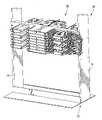
- FIG. 1is a perspective view of a communications rack with a telecommunications patching assembly according to embodiments of the present invention.
- FIG. 2is a perspective view of the module mounting bay of the telecommunications patching system of the assembly of FIG. 1 .
- FIG. 3is a perspective view of an exemplary connector, patch cord and cables of the patching system of FIG. 1 .
- FIG. 4is a perspective view of an exemplary termination module of the system of FIG. 1 .
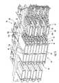
- FIG. 5is a perspective view of the telecommunications system of FIG. 1 with patching modules loaded into some of the compartments thereof.
- FIG. 6is an enlarged front view of the system of FIG. 5 .
- FIG. 7is a side perspective view of the system of FIG. 5 with one of the modules in an access position.
- spatially relative termssuch as “under”, “below”, “lower”, “over”, “upper” and the like, may be used herein for ease of description to describe one element or feature's relationship to another element(s) or feature(s) as illustrated in the figures. It will be understood that the spatially relative terms are intended to encompass different orientations of the device in use or operation in addition to the orientation depicted in the figures. For example, if the device in the figures is turned over, elements described as “under” or “beneath” other elements or features would then be oriented “over” or “above” the other elements or features. Thus, the exemplary term “under” can encompass both an orientation of over and under. The device may be otherwise oriented (rotated 90 degrees or at other orientations) and the spatially relative descriptors used herein interpreted accordingly.
- a connectoris intended to encompass telecommunications connectors and devices employed to facilitate the interconnection of telecommunications cords and cables for the transmission of signals therebetween.
- a connectormay include a termination device at the end of a cord or cable, an adapter that facilitates the interconnection of two termination devices (as may be employed in the interconnection of fiber optic cords and cables, such as may be found in a connector block), a jack, plug, or the like typically employed with copper cables and cords, or other devices that provide a location for the interconnection of cables and cords.
- the rack 10includes a frame 12 having two vertical, spaced apart uprights 14 . Each of the uprights 14 includes mounting holes for the mounting of patching systems 20 . Although only one patching system 20 is shown mounted therein, the rack 10 may (and typically will) include multiple termination module systems 20 .
- the patching system 20includes a module mounting bay 22 .
- the mounting bay 22has a rear wall 23 with lateral apertures 23 a via which the patching system 20 can be mounted to the uprights 14 .
- Spacing walls 39which help to guide the mounting bay 22 during mounting on the uprights 22 , extend rearwardly from the rear wall 23 .
- the terms “front,” “forward”, and derivatives thereofrefer to the direction defined by a vector originating at the rear wall 23 and extending perpendicular thereto and away from the spacing walls 39 .
- the term “rear” and derivatives thereofrefer to the direction opposite that of the forward direction, i.e., the direction defined by a vector originating at the rear wall 23 and extending perpendicular thereto and toward the spacing walls 39 .
- the forward and rear directionscomprise the “longitudinal” dimensions of the device.
- the term “lateral” and derivatives thereofrefer to the direction originating at the center point of the rear wall 23 and extending parallel to the rear wall 23 and toward the uprights 14 of the frame 12 .
- one structureis described as being “lateral” of another structure, it is located farther from the center point of the rear wall 23 than the second structure.
- the terms “inner,” “inboard” and derivatives thereofrefer to the direction opposite the lateral direction.
- the lateral and inboard directionscomprise the “transverse” dimensions of the device.
- the mounting bay 22also includes a central shelf unit 24 and lateral shelf units 28 .
- the central shelf unit 24includes a plurality of partitions 27 that extend laterally from central guide walls 25 , thereby forming a series of compartments 26 .
- the compartments 26are disposed in adjacent, vertically stacked relationship.
- the compartments 26are arranged in two columns, although in other embodiments other numbers of columns may be employed.
- Each guide wall 25is stepped, such that a recess 25 a is formed on each side, with the recesses 25 a in one side of the guide walls 25 (in FIG.
- a guide flange 25 bextends into each recess 25 a (upwardly for the left compartments 26 , and downwardly for the right compartments 26 ). Cutouts 36 in the rear wall 23 align with the compartments 26 ; i.e., the cutouts 36 are located to enable objects residing in the compartments 26 to pass or extend through the rear wall 23 .
- the mounting bay 22also includes lateral shelf units 28 mounted on either side of the central shelf unit 24 .
- Each of the lateral shelf units 28includes a vertical wall 32 with recesses 32 a and guide flanges 32 b .
- Partitions 30extend laterally from the vertical wall 32 to form compartments 34 .
- the guide flanges 32 bextend downwardly from an upper partition 30 into the recesses 32 a in the right hand compartments 34 and upwardly from the lower partitions 30 in the left hand compartments 34 .
- cutouts 37 in the rear wall 23align with the compartments 34 .
- the compartments 34are separated from each other by gaps 38 , such that the compartments 34 are in spaced apart, vertically stacked relationship.
- the compartments 34are vertically offset from their adjacent compartments 26 of the central shelf unit 23 (i.e., the central “step” of the vertical wall 32 of a lateral compartment 34 is at the same elevation as a partition 27 of the central shelf unit 24 ).
- the patching module 60is exemplary of and identical to multiple patching modules 60 of the system 10 ; as such, only one patching module 60 will be described therein, with the understanding that the description is equally applicable to the other patching modules 60 .
- the patching module 60has an elongate floor 62 that includes, in the illustrated embodiment, two fiber guides 66 for guiding optical fiber as it is routed through the module 60 to prevent damage and preserve operability of the optical fiber (in this illustrative example, two semi-circular fiber guides 66 are shown, but any number and/or shape of fiber guide 66 may be used).
- Connector mounts 64are positioned in a row along a lateral edge of the floor 62 .
- the module 60also includes a slide guide 68 having an L-shaped cross-section on the edge of the floor 62 opposite the connector mounts 64 . At its front edge, the module 60 includes a tab 70 that extends from the front wall 72 of the module 60 for easy handling of the module 60 .
- FIG. 3an exemplary optical connector 50 is shown therein. Patch cords 52 are illustrated entering one end of the connector 50 , and cables 54 are shown entering the opposite side of the connector 50 .
- the connector 50is mounted in one of the connector mounts 64 in the module 60 (see FIG. 4 ).
- FIGS. 5 and 6the assembled patching system 20 is shown therein.
- all of the central and lateral compartments 26 , 34are populated with patching modules 60 (although only those on the right half of the system 20 are connected to patch cords 52 ); in FIG. 6 , only one side of the central shelf unit 24 and one lateral shelf unit 28 include patching modules 60 and patch cords 52 .
- each of the compartments 26 of the central shelf unit 24houses a termination module 60 .
- the rear end of each module 60 in the central shelf unit 24passes through the cutout 36 of its respective compartment 26 and extends rearwardly therefrom behind the rear wall 23 .
- the slide guide 68 of module 60fits within the recess 25 a of its respective compartment 26 and is captured by the flange 25 b .
- the modules 60 on one side of the central divider 25are oriented so that the fiber guides 62 face downwardly (i.e., they are inverted from their orientation in FIG. 4 ).
- Modules 60 on the other side of the guide walls 25would be oriented so that the fiber guides 62 face upwardly.
- the connector mounts 64 and connectors 50face away from the guide walls 25 (i.e., they face laterally) and are laterally accessible for interconnection with patch cords 52 .
- each of the compartments 34 of the lateral shelf units 28is filled with a module 60 .
- the module 60extends through the cutout 37 in the rear wall 23 associated with its compartment 34 , and its slide guide 68 fits within the recess 32 a in the vertical wall 32 and is held in place by the flange 32 b .
- the modules 60 that reside in the lateral shelf units 28are oriented so that the connector mounts 64 and connectors 50 face laterally.
- patch cords 52are connected to the connectors 50 mounted in the connector mounts 64 .
- the patch cords 52approach from the lateral direction for connection with the connectors 50 mounted in modules 60 located in the compartments 26 , 34 .
- the patch cords 52 that attach to the modules 60 located in the compartments 26 of the central shelf unit 24are largely routed through the gaps 38 between the compartments 34 of the lateral shelf unit 28 (the exceptions are the patch cords 52 that connect to the uppermost and lowermost modules 60 in the central shelf unit 23 , which pass above the uppermost and below the lowermost compartments 34 of the lateral shelf unit 28 ).
- the illustrated arrangement of modules 60 and patch cords 52can enable the density of the system 20 to be increased.
- the illustrated module system 20with sixteen modules 60 housed in the central shelf unit 23 (in two “stacks” of eight modules) and four modules 60 housed in each of the lateral shelf units 28 , is typically about 4 U in height. With this arrangement, the density of connections can be as high as 48 ports/U or more.
- the front wall 72provides a suitable space for affixing a label.
- a labelcan provide information about the identity of the connections made with the connectors 50 .
- FIG. 7illustrates the access position that can be achieved with the modules 60 .
- a module 60can be slid forward within its compartment 26 , 34 to enable a technician to connect or disconnect patch cords 52 or cables from the connectors 50 of the module 60 . Sliding the modules 60 forward provides easy access to the connectors 50 , cords 52 and cables 54 . Because the patch cords 52 of the modules 60 are routed through the gaps 38 between the compartments 34 of the lateral shelf units 28 , they can also slide forward with the module 60 without the need for disconnection.
Landscapes
- Physics & Mathematics (AREA)
- Engineering & Computer Science (AREA)
- Computer Networks & Wireless Communication (AREA)
- General Physics & Mathematics (AREA)
- Optics & Photonics (AREA)
- Structure Of Telephone Exchanges (AREA)
- Light Guides In General And Applications Therefor (AREA)
Abstract
Description
Claims (27)
Priority Applications (3)
| Application Number | Priority Date | Filing Date | Title |
|---|---|---|---|
| US12/275,457US7672561B1 (en) | 2008-10-02 | 2008-11-21 | Telecommunications patching system with patching modules |
| GB0917183AGB2463986B (en) | 2008-10-02 | 2009-10-01 | Telecommunications patching system with patching modules |
| CN200910211651.4ACN101729925B (en) | 2008-10-02 | 2009-10-09 | Telecom distribution system with distribution modules |
Applications Claiming Priority (2)
| Application Number | Priority Date | Filing Date | Title |
|---|---|---|---|
| US24418908A | 2008-10-02 | 2008-10-02 | |
| US12/275,457US7672561B1 (en) | 2008-10-02 | 2008-11-21 | Telecommunications patching system with patching modules |
Related Parent Applications (1)
| Application Number | Title | Priority Date | Filing Date |
|---|---|---|---|
| US24418908AContinuation-In-Part | 2008-10-02 | 2008-10-02 |
Publications (1)
| Publication Number | Publication Date |
|---|---|
| US7672561B1true US7672561B1 (en) | 2010-03-02 |
Family
ID=41393670
Family Applications (1)
| Application Number | Title | Priority Date | Filing Date |
|---|---|---|---|
| US12/275,457Expired - Fee RelatedUS7672561B1 (en) | 2008-10-02 | 2008-11-21 | Telecommunications patching system with patching modules |
Country Status (3)
| Country | Link |
|---|---|
| US (1) | US7672561B1 (en) |
| CN (1) | CN101729925B (en) |
| GB (1) | GB2463986B (en) |
Cited By (53)
| Publication number | Priority date | Publication date | Assignee | Title |
|---|---|---|---|---|
| US20100105244A1 (en)* | 2008-10-29 | 2010-04-29 | Scott Martin Keith | Telecommunications Patching Systems with Obliquely-Angled Patching Modules |
| US20100296791A1 (en)* | 2009-05-21 | 2010-11-25 | Elli Makrides-Saravanos | Fiber Optic Equipment Guides and Rails Configured with Stopping Position(s), and Related Equipment and Methods |
| US7856166B2 (en) | 2008-09-02 | 2010-12-21 | Corning Cable Systems Llc | High-density patch-panel assemblies for optical fiber telecommunications |
| US20100322583A1 (en)* | 2009-06-19 | 2010-12-23 | Cooke Terry L | High Density and Bandwidth Fiber Optic Apparatuses and Related Equipment and Methods |
| US20110268405A1 (en)* | 2010-04-30 | 2011-11-03 | Cote Monique L | Stackable shelves for a fiber optic housing, and related components and methods |
| US8433171B2 (en) | 2009-06-19 | 2013-04-30 | Corning Cable Systems Llc | High fiber optic cable packing density apparatus |
| US8542973B2 (en) | 2010-04-23 | 2013-09-24 | Ccs Technology, Inc. | Fiber optic distribution device |
| US8593828B2 (en) | 2010-02-04 | 2013-11-26 | Corning Cable Systems Llc | Communications equipment housings, assemblies, and related alignment features and methods |
| US8625950B2 (en) | 2009-12-18 | 2014-01-07 | Corning Cable Systems Llc | Rotary locking apparatus for fiber optic equipment trays and related methods |
| US8660397B2 (en) | 2010-04-30 | 2014-02-25 | Corning Cable Systems Llc | Multi-layer module |
| US8662760B2 (en) | 2010-10-29 | 2014-03-04 | Corning Cable Systems Llc | Fiber optic connector employing optical fiber guide member |
| US8699838B2 (en) | 2009-05-14 | 2014-04-15 | Ccs Technology, Inc. | Fiber optic furcation module |
| US8705926B2 (en) | 2010-04-30 | 2014-04-22 | Corning Optical Communications LLC | Fiber optic housings having a removable top, and related components and methods |
| US8712206B2 (en) | 2009-06-19 | 2014-04-29 | Corning Cable Systems Llc | High-density fiber optic modules and module housings and related equipment |
| US8718436B2 (en) | 2010-08-30 | 2014-05-06 | Corning Cable Systems Llc | Methods, apparatuses for providing secure fiber optic connections |
| US8879881B2 (en) | 2010-04-30 | 2014-11-04 | Corning Cable Systems Llc | Rotatable routing guide and assembly |
| US8913866B2 (en) | 2010-03-26 | 2014-12-16 | Corning Cable Systems Llc | Movable adapter panel |
| US8953924B2 (en) | 2011-09-02 | 2015-02-10 | Corning Cable Systems Llc | Removable strain relief brackets for securing fiber optic cables and/or optical fibers to fiber optic equipment, and related assemblies and methods |
| US8985862B2 (en) | 2013-02-28 | 2015-03-24 | Corning Cable Systems Llc | High-density multi-fiber adapter housings |
| US8989547B2 (en) | 2011-06-30 | 2015-03-24 | Corning Cable Systems Llc | Fiber optic equipment assemblies employing non-U-width-sized housings and related methods |
| US8995812B2 (en) | 2012-10-26 | 2015-03-31 | Ccs Technology, Inc. | Fiber optic management unit and fiber optic distribution device |
| US9008485B2 (en) | 2011-05-09 | 2015-04-14 | Corning Cable Systems Llc | Attachment mechanisms employed to attach a rear housing section to a fiber optic housing, and related assemblies and methods |
| US9022814B2 (en) | 2010-04-16 | 2015-05-05 | Ccs Technology, Inc. | Sealing and strain relief device for data cables |
| US9038832B2 (en) | 2011-11-30 | 2015-05-26 | Corning Cable Systems Llc | Adapter panel support assembly |
| US9042702B2 (en) | 2012-09-18 | 2015-05-26 | Corning Cable Systems Llc | Platforms and systems for fiber optic cable attachment |
| US9059578B2 (en) | 2009-02-24 | 2015-06-16 | Ccs Technology, Inc. | Holding device for a cable or an assembly for use with a cable |
| US9075216B2 (en) | 2009-05-21 | 2015-07-07 | Corning Cable Systems Llc | Fiber optic housings configured to accommodate fiber optic modules/cassettes and fiber optic panels, and related components and methods |
| US9075217B2 (en) | 2010-04-30 | 2015-07-07 | Corning Cable Systems Llc | Apparatuses and related components and methods for expanding capacity of fiber optic housings |
| US9097872B2 (en) | 2011-11-08 | 2015-08-04 | Optical Cable Corporation | High density telecommunications patching system and cassettes |
| US9116324B2 (en) | 2010-10-29 | 2015-08-25 | Corning Cable Systems Llc | Stacked fiber optic modules and fiber optic equipment configured to support stacked fiber optic modules |
| US9213161B2 (en) | 2010-11-05 | 2015-12-15 | Corning Cable Systems Llc | Fiber body holder and strain relief device |
| US9250409B2 (en) | 2012-07-02 | 2016-02-02 | Corning Cable Systems Llc | Fiber-optic-module trays and drawers for fiber-optic equipment |
| US9279951B2 (en) | 2010-10-27 | 2016-03-08 | Corning Cable Systems Llc | Fiber optic module for limited space applications having a partially sealed module sub-assembly |
| US9285546B2 (en) | 2014-06-04 | 2016-03-15 | All Systems Broadband, Inc. | Conduit for passing a plurality of fiber optic cables through a fiber optic cassette shelf |
| US9395508B1 (en)* | 2012-01-06 | 2016-07-19 | Google Inc. | Interchangeable rack system |
| US9519118B2 (en) | 2010-04-30 | 2016-12-13 | Corning Optical Communications LLC | Removable fiber management sections for fiber optic housings, and related components and methods |
| US9632270B2 (en) | 2010-04-30 | 2017-04-25 | Corning Optical Communications LLC | Fiber optic housings configured for tool-less assembly, and related components and methods |
| US9645317B2 (en) | 2011-02-02 | 2017-05-09 | Corning Optical Communications LLC | Optical backplane extension modules, and related assemblies suitable for establishing optical connections to information processing modules disposed in equipment racks |
| US9690065B2 (en) | 2014-09-12 | 2017-06-27 | Panduit Corp. | High density fiber enclosure and method |
| US9720195B2 (en) | 2010-04-30 | 2017-08-01 | Corning Optical Communications LLC | Apparatuses and related components and methods for attachment and release of fiber optic housings to and from an equipment rack |
| EP3361846A1 (en)* | 2017-02-13 | 2018-08-15 | Reichle & De-Massari AG | Cable management device |
| US10094996B2 (en) | 2008-08-29 | 2018-10-09 | Corning Optical Communications, Llc | Independently translatable modules and fiber optic equipment trays in fiber optic equipment |
| US10215944B2 (en) | 2016-06-30 | 2019-02-26 | Panduit Corp. | Modular fiber optic tray |
| US20190075375A1 (en)* | 2016-04-08 | 2019-03-07 | Commscope, Inc. Of North Carolina | Cable management assembly |
| US20210278618A1 (en)* | 2018-10-23 | 2021-09-09 | CommScope Connectivity Belgium BVBA | Frame assemblies for optical fiber distribution elements |
| US11294136B2 (en) | 2008-08-29 | 2022-04-05 | Corning Optical Communications LLC | High density and bandwidth fiber optic apparatuses and related equipment and methods |
| US11982855B2 (en) | 2013-04-24 | 2024-05-14 | CommScope Connectivity Belgium BVBA | Universal mounting mechanism for mounting a telecommunications chassis to a telecommunications fixture |
| US12050358B2 (en) | 2018-08-31 | 2024-07-30 | CommScope Connectivity Belgium BVBA | Frame assemblies for optical fiber distribution elements |
| US12189188B2 (en) | 2018-08-31 | 2025-01-07 | CommScope Connectivity Belgium BVBA | Frame assemblies for optical fiber distribution elements |
| US12197025B2 (en) | 2018-08-31 | 2025-01-14 | CommScope Connectivity Belgium BVBA | Frame assemblies for optical fiber distribution elements |
| US12197027B2 (en) | 2018-08-31 | 2025-01-14 | CommScope Connectivity Belgium BVBA | Frame assemblies for optical fiber distribution elements |
| US12197026B2 (en) | 2018-08-31 | 2025-01-14 | CommScope Connectivity Belgium BVBA | Frame assemblies for optical fiber distribution elements |
| US12422640B2 (en) | 2013-01-29 | 2025-09-23 | CommScope Connectivity Belgium BVBA | Optical fiber distribution system |
Families Citing this family (1)
| Publication number | Priority date | Publication date | Assignee | Title |
|---|---|---|---|---|
| EP2725396B1 (en)* | 2012-10-26 | 2016-09-14 | CCS Technology, Inc. | Strain relief device for cables and fiber optic distribution device |
Citations (14)
| Publication number | Priority date | Publication date | Assignee | Title |
|---|---|---|---|---|
| US5339379A (en) | 1993-06-18 | 1994-08-16 | Telect, Inc. | Telecommunication fiber optic cable distribution apparatus |
| US6236795B1 (en) | 1999-06-07 | 2001-05-22 | E. Walter Rodgers | High-density fiber optic cable distribution frame |
| US6293707B1 (en) | 1999-02-19 | 2001-09-25 | Lucent Technologies Inc. | Patch panel with pivoting bracket assembly |
| US6362422B1 (en) | 2000-06-02 | 2002-03-26 | Michael T. Vavrik | Enclosure for use in fiber optic management systems |
| US6418262B1 (en) | 2000-03-13 | 2002-07-09 | Adc Telecommunications, Inc. | Fiber distribution frame with fiber termination blocks |
| US6424781B1 (en) | 1999-03-01 | 2002-07-23 | Adc Telecommunications, Inc. | Optical fiber distribution frame with pivoting connector panels |
| US20020129959A1 (en) | 2001-03-19 | 2002-09-19 | Petersen Cyle D. | Cable management rack and chassis system |
| US20020141720A1 (en)* | 2001-04-03 | 2002-10-03 | Ross Halgren | Rack structure |
| US20020150372A1 (en) | 2001-02-12 | 2002-10-17 | Fiber Optic Network Solutions Corp. | Optical fiber enclosure system |
| US6535682B1 (en) | 1999-03-01 | 2003-03-18 | Adc Telecommunications, Inc. | Optical fiber distribution frame with connector modules |
| US6556763B1 (en) | 1999-03-01 | 2003-04-29 | Adc Telecommunications, Inc. | Optical fiber distribution frame with connector modules |
| US6614978B1 (en) | 2000-06-02 | 2003-09-02 | Panduit Corp. | Slack cable management system |
| US7123808B2 (en)* | 2004-11-19 | 2006-10-17 | Tyco Electronics Corporation | Cable management system |
| US20080002937A1 (en) | 2006-06-29 | 2008-01-03 | Gordon Spisany | Patch panels with communications connectors that are rotatable about a vertical axis |
Family Cites Families (4)
| Publication number | Priority date | Publication date | Assignee | Title |
|---|---|---|---|---|
| AU4892485A (en)* | 1984-10-26 | 1986-05-01 | Adc Telecommunications, Incorporated | Modular distribution frame |
| GB9801198D0 (en)* | 1998-01-21 | 1998-03-18 | Raychem Sa Nv | Optical fibre assembly |
| US6974348B2 (en)* | 2004-03-04 | 2005-12-13 | Commscope Solutions Properties, Llc. | High-density multi-port-module patch panel system |
| US7220145B2 (en)* | 2004-04-14 | 2007-05-22 | Tyco Electronics Corporation | Patch panel system |
- 2008
- 2008-11-21USUS12/275,457patent/US7672561B1/ennot_activeExpired - Fee Related
- 2009
- 2009-10-01GBGB0917183Apatent/GB2463986B/ennot_activeExpired - Fee Related
- 2009-10-09CNCN200910211651.4Apatent/CN101729925B/ennot_activeExpired - Fee Related
Patent Citations (15)
| Publication number | Priority date | Publication date | Assignee | Title |
|---|---|---|---|---|
| US5339379A (en) | 1993-06-18 | 1994-08-16 | Telect, Inc. | Telecommunication fiber optic cable distribution apparatus |
| US6293707B1 (en) | 1999-02-19 | 2001-09-25 | Lucent Technologies Inc. | Patch panel with pivoting bracket assembly |
| US6535682B1 (en) | 1999-03-01 | 2003-03-18 | Adc Telecommunications, Inc. | Optical fiber distribution frame with connector modules |
| US6424781B1 (en) | 1999-03-01 | 2002-07-23 | Adc Telecommunications, Inc. | Optical fiber distribution frame with pivoting connector panels |
| US6556763B1 (en) | 1999-03-01 | 2003-04-29 | Adc Telecommunications, Inc. | Optical fiber distribution frame with connector modules |
| US6236795B1 (en) | 1999-06-07 | 2001-05-22 | E. Walter Rodgers | High-density fiber optic cable distribution frame |
| US6418262B1 (en) | 2000-03-13 | 2002-07-09 | Adc Telecommunications, Inc. | Fiber distribution frame with fiber termination blocks |
| US6362422B1 (en) | 2000-06-02 | 2002-03-26 | Michael T. Vavrik | Enclosure for use in fiber optic management systems |
| US6614978B1 (en) | 2000-06-02 | 2003-09-02 | Panduit Corp. | Slack cable management system |
| US20020150372A1 (en) | 2001-02-12 | 2002-10-17 | Fiber Optic Network Solutions Corp. | Optical fiber enclosure system |
| US6845207B2 (en) | 2001-02-12 | 2005-01-18 | Fiber Optic Network Solutions Corp. | Optical fiber enclosure system |
| US20020129959A1 (en) | 2001-03-19 | 2002-09-19 | Petersen Cyle D. | Cable management rack and chassis system |
| US20020141720A1 (en)* | 2001-04-03 | 2002-10-03 | Ross Halgren | Rack structure |
| US7123808B2 (en)* | 2004-11-19 | 2006-10-17 | Tyco Electronics Corporation | Cable management system |
| US20080002937A1 (en) | 2006-06-29 | 2008-01-03 | Gordon Spisany | Patch panels with communications connectors that are rotatable about a vertical axis |
Non-Patent Citations (1)
| Title |
|---|
| ADC Telecommunications, Inc. Brochure: "Room to Grow", one page, Website: www.adc.com/truenet, (2007). |
Cited By (95)
| Publication number | Priority date | Publication date | Assignee | Title |
|---|---|---|---|---|
| US9020320B2 (en) | 2008-08-29 | 2015-04-28 | Corning Cable Systems Llc | High density and bandwidth fiber optic apparatuses and related equipment and methods |
| US10852499B2 (en) | 2008-08-29 | 2020-12-01 | Corning Optical Communications LLC | High density and bandwidth fiber optic apparatuses and related equipment and methods |
| US10094996B2 (en) | 2008-08-29 | 2018-10-09 | Corning Optical Communications, Llc | Independently translatable modules and fiber optic equipment trays in fiber optic equipment |
| US10120153B2 (en) | 2008-08-29 | 2018-11-06 | Corning Optical Communications, Llc | Independently translatable modules and fiber optic equipment trays in fiber optic equipment |
| US10126514B2 (en) | 2008-08-29 | 2018-11-13 | Corning Optical Communications, Llc | Independently translatable modules and fiber optic equipment trays in fiber optic equipment |
| US10416405B2 (en) | 2008-08-29 | 2019-09-17 | Corning Optical Communications LLC | Independently translatable modules and fiber optic equipment trays in fiber optic equipment |
| US11086089B2 (en) | 2008-08-29 | 2021-08-10 | Corning Optical Communications LLC | High density and bandwidth fiber optic apparatuses and related equipment and methods |
| US11754796B2 (en) | 2008-08-29 | 2023-09-12 | Corning Optical Communications LLC | Independently translatable modules and fiber optic equipment trays in fiber optic equipment |
| US10222570B2 (en) | 2008-08-29 | 2019-03-05 | Corning Optical Communications LLC | Independently translatable modules and fiber optic equipment trays in fiber optic equipment |
| US11609396B2 (en) | 2008-08-29 | 2023-03-21 | Corning Optical Communications LLC | High density and bandwidth fiber optic apparatuses and related equipment and methods |
| US9910236B2 (en) | 2008-08-29 | 2018-03-06 | Corning Optical Communications LLC | High density and bandwidth fiber optic apparatuses and related equipment and methods |
| US10564378B2 (en) | 2008-08-29 | 2020-02-18 | Corning Optical Communications LLC | High density and bandwidth fiber optic apparatuses and related equipment and methods |
| US11294135B2 (en) | 2008-08-29 | 2022-04-05 | Corning Optical Communications LLC | High density and bandwidth fiber optic apparatuses and related equipment and methods |
| US11092767B2 (en) | 2008-08-29 | 2021-08-17 | Corning Optical Communications LLC | High density and bandwidth fiber optic apparatuses and related equipment and methods |
| US10606014B2 (en) | 2008-08-29 | 2020-03-31 | Corning Optical Communications LLC | Independently translatable modules and fiber optic equipment trays in fiber optic equipment |
| US11294136B2 (en) | 2008-08-29 | 2022-04-05 | Corning Optical Communications LLC | High density and bandwidth fiber optic apparatuses and related equipment and methods |
| US10459184B2 (en) | 2008-08-29 | 2019-10-29 | Corning Optical Communications LLC | High density and bandwidth fiber optic apparatuses and related equipment and methods |
| US10422971B2 (en) | 2008-08-29 | 2019-09-24 | Corning Optical Communicatinos LLC | High density and bandwidth fiber optic apparatuses and related equipment and methods |
| US12072545B2 (en) | 2008-08-29 | 2024-08-27 | Corning Optical Communications LLC | High density and bandwidth fiber optic apparatuses and related equipment and methods |
| US10444456B2 (en) | 2008-08-29 | 2019-10-15 | Corning Optical Communications LLC | High density and bandwidth fiber optic apparatuses and related equipment and methods |
| US20110085776A1 (en)* | 2008-09-02 | 2011-04-14 | Eric Biribuze | High-Density Patch-Panel Assemblies for Optical Fiber Telecommunications |
| US7856166B2 (en) | 2008-09-02 | 2010-12-21 | Corning Cable Systems Llc | High-density patch-panel assemblies for optical fiber telecommunications |
| US8331752B2 (en) | 2008-09-02 | 2012-12-11 | Corning Cable Systems Llc | High-density patch-panel assemblies for optical fiber telecommunications |
| US7876995B2 (en)* | 2008-10-29 | 2011-01-25 | Commscope, Inc. Of North Carolina | Telecommunications patching systems with obliquely-angled patching modules |
| US20100105244A1 (en)* | 2008-10-29 | 2010-04-29 | Scott Martin Keith | Telecommunications Patching Systems with Obliquely-Angled Patching Modules |
| US9059578B2 (en) | 2009-02-24 | 2015-06-16 | Ccs Technology, Inc. | Holding device for a cable or an assembly for use with a cable |
| US8699838B2 (en) | 2009-05-14 | 2014-04-15 | Ccs Technology, Inc. | Fiber optic furcation module |
| US8538226B2 (en) | 2009-05-21 | 2013-09-17 | Corning Cable Systems Llc | Fiber optic equipment guides and rails configured with stopping position(s), and related equipment and methods |
| US9075216B2 (en) | 2009-05-21 | 2015-07-07 | Corning Cable Systems Llc | Fiber optic housings configured to accommodate fiber optic modules/cassettes and fiber optic panels, and related components and methods |
| US20100296791A1 (en)* | 2009-05-21 | 2010-11-25 | Elli Makrides-Saravanos | Fiber Optic Equipment Guides and Rails Configured with Stopping Position(s), and Related Equipment and Methods |
| US8433171B2 (en) | 2009-06-19 | 2013-04-30 | Corning Cable Systems Llc | High fiber optic cable packing density apparatus |
| US8712206B2 (en) | 2009-06-19 | 2014-04-29 | Corning Cable Systems Llc | High-density fiber optic modules and module housings and related equipment |
| US20100322583A1 (en)* | 2009-06-19 | 2010-12-23 | Cooke Terry L | High Density and Bandwidth Fiber Optic Apparatuses and Related Equipment and Methods |
| US8625950B2 (en) | 2009-12-18 | 2014-01-07 | Corning Cable Systems Llc | Rotary locking apparatus for fiber optic equipment trays and related methods |
| US8593828B2 (en) | 2010-02-04 | 2013-11-26 | Corning Cable Systems Llc | Communications equipment housings, assemblies, and related alignment features and methods |
| US8992099B2 (en) | 2010-02-04 | 2015-03-31 | Corning Cable Systems Llc | Optical interface cards, assemblies, and related methods, suited for installation and use in antenna system equipment |
| US8913866B2 (en) | 2010-03-26 | 2014-12-16 | Corning Cable Systems Llc | Movable adapter panel |
| US9022814B2 (en) | 2010-04-16 | 2015-05-05 | Ccs Technology, Inc. | Sealing and strain relief device for data cables |
| US8542973B2 (en) | 2010-04-23 | 2013-09-24 | Ccs Technology, Inc. | Fiber optic distribution device |
| US8705926B2 (en) | 2010-04-30 | 2014-04-22 | Corning Optical Communications LLC | Fiber optic housings having a removable top, and related components and methods |
| US9519118B2 (en) | 2010-04-30 | 2016-12-13 | Corning Optical Communications LLC | Removable fiber management sections for fiber optic housings, and related components and methods |
| US9632270B2 (en) | 2010-04-30 | 2017-04-25 | Corning Optical Communications LLC | Fiber optic housings configured for tool-less assembly, and related components and methods |
| US9075217B2 (en) | 2010-04-30 | 2015-07-07 | Corning Cable Systems Llc | Apparatuses and related components and methods for expanding capacity of fiber optic housings |
| US20110268405A1 (en)* | 2010-04-30 | 2011-11-03 | Cote Monique L | Stackable shelves for a fiber optic housing, and related components and methods |
| US8660397B2 (en) | 2010-04-30 | 2014-02-25 | Corning Cable Systems Llc | Multi-layer module |
| US9720195B2 (en) | 2010-04-30 | 2017-08-01 | Corning Optical Communications LLC | Apparatuses and related components and methods for attachment and release of fiber optic housings to and from an equipment rack |
| US8879881B2 (en) | 2010-04-30 | 2014-11-04 | Corning Cable Systems Llc | Rotatable routing guide and assembly |
| US8718436B2 (en) | 2010-08-30 | 2014-05-06 | Corning Cable Systems Llc | Methods, apparatuses for providing secure fiber optic connections |
| US9279951B2 (en) | 2010-10-27 | 2016-03-08 | Corning Cable Systems Llc | Fiber optic module for limited space applications having a partially sealed module sub-assembly |
| US9116324B2 (en) | 2010-10-29 | 2015-08-25 | Corning Cable Systems Llc | Stacked fiber optic modules and fiber optic equipment configured to support stacked fiber optic modules |
| US8662760B2 (en) | 2010-10-29 | 2014-03-04 | Corning Cable Systems Llc | Fiber optic connector employing optical fiber guide member |
| US9213161B2 (en) | 2010-11-05 | 2015-12-15 | Corning Cable Systems Llc | Fiber body holder and strain relief device |
| US10481335B2 (en) | 2011-02-02 | 2019-11-19 | Corning Optical Communications, Llc | Dense shuttered fiber optic connectors and assemblies suitable for establishing optical connections for optical backplanes in equipment racks |
| US9645317B2 (en) | 2011-02-02 | 2017-05-09 | Corning Optical Communications LLC | Optical backplane extension modules, and related assemblies suitable for establishing optical connections to information processing modules disposed in equipment racks |
| US9008485B2 (en) | 2011-05-09 | 2015-04-14 | Corning Cable Systems Llc | Attachment mechanisms employed to attach a rear housing section to a fiber optic housing, and related assemblies and methods |
| US8989547B2 (en) | 2011-06-30 | 2015-03-24 | Corning Cable Systems Llc | Fiber optic equipment assemblies employing non-U-width-sized housings and related methods |
| US8953924B2 (en) | 2011-09-02 | 2015-02-10 | Corning Cable Systems Llc | Removable strain relief brackets for securing fiber optic cables and/or optical fibers to fiber optic equipment, and related assemblies and methods |
| US9097872B2 (en) | 2011-11-08 | 2015-08-04 | Optical Cable Corporation | High density telecommunications patching system and cassettes |
| US9666999B2 (en) | 2011-11-08 | 2017-05-30 | Optical Cable Corporation | Telecommunications patching system having moveable cassettes |
| US9038832B2 (en) | 2011-11-30 | 2015-05-26 | Corning Cable Systems Llc | Adapter panel support assembly |
| US9395508B1 (en)* | 2012-01-06 | 2016-07-19 | Google Inc. | Interchangeable rack system |
| US9250409B2 (en) | 2012-07-02 | 2016-02-02 | Corning Cable Systems Llc | Fiber-optic-module trays and drawers for fiber-optic equipment |
| US9042702B2 (en) | 2012-09-18 | 2015-05-26 | Corning Cable Systems Llc | Platforms and systems for fiber optic cable attachment |
| US8995812B2 (en) | 2012-10-26 | 2015-03-31 | Ccs Technology, Inc. | Fiber optic management unit and fiber optic distribution device |
| US12422640B2 (en) | 2013-01-29 | 2025-09-23 | CommScope Connectivity Belgium BVBA | Optical fiber distribution system |
| US8985862B2 (en) | 2013-02-28 | 2015-03-24 | Corning Cable Systems Llc | High-density multi-fiber adapter housings |
| US11982855B2 (en) | 2013-04-24 | 2024-05-14 | CommScope Connectivity Belgium BVBA | Universal mounting mechanism for mounting a telecommunications chassis to a telecommunications fixture |
| US9285546B2 (en) | 2014-06-04 | 2016-03-15 | All Systems Broadband, Inc. | Conduit for passing a plurality of fiber optic cables through a fiber optic cassette shelf |
| US9690065B2 (en) | 2014-09-12 | 2017-06-27 | Panduit Corp. | High density fiber enclosure and method |
| US11624888B2 (en) | 2014-09-12 | 2023-04-11 | Panduit Corp. | High density fiber enclosure and method |
| US9864158B2 (en) | 2014-09-12 | 2018-01-09 | Panduit Corp. | High density fiber enclosure and method |
| US10698171B2 (en) | 2014-09-12 | 2020-06-30 | Panduit Corp. | High density fiber enclosure and method |
| US10606013B2 (en) | 2014-09-12 | 2020-03-31 | Panduit Corp. | High density fiber enclosure and method |
| US11105995B2 (en) | 2014-09-12 | 2021-08-31 | Panduit Corp. | High density fiber enclosure and method |
| US12228782B2 (en) | 2014-09-12 | 2025-02-18 | Panduit Corp. | High density fiber enclosure and method |
| US10317637B2 (en) | 2014-09-12 | 2019-06-11 | Panduit Corp. | High density fiber enclosure and method |
| US10268013B2 (en) | 2014-09-12 | 2019-04-23 | Panduit Corp. | High density fiber enclosure and method |
| US10768385B2 (en) | 2014-09-12 | 2020-09-08 | Panduit Corp. | High density fiber enclosure and method |
| US11502488B2 (en)* | 2016-04-08 | 2022-11-15 | Commscope Inc. Of North Carolina | Cable management assembly for variable length cables |
| US20190075375A1 (en)* | 2016-04-08 | 2019-03-07 | Commscope, Inc. Of North Carolina | Cable management assembly |
| US11709331B2 (en) | 2016-06-30 | 2023-07-25 | Panduit Corp. | Modular fiber optic tray |
| US12105338B2 (en) | 2016-06-30 | 2024-10-01 | Panduit Corp. | Modular fiber optic tray |
| US10215944B2 (en) | 2016-06-30 | 2019-02-26 | Panduit Corp. | Modular fiber optic tray |
| US10725258B2 (en) | 2016-06-30 | 2020-07-28 | Panduit Corp. | Modular fiber optic tray |
| US11372185B2 (en) | 2016-06-30 | 2022-06-28 | Panduit Corp. | Modular fiber optic tray |
| EP3361845A1 (en)* | 2017-02-13 | 2018-08-15 | Reichle & De-Massari AG | Cable management device |
| EP3361846A1 (en)* | 2017-02-13 | 2018-08-15 | Reichle & De-Massari AG | Cable management device |
| US12197027B2 (en) | 2018-08-31 | 2025-01-14 | CommScope Connectivity Belgium BVBA | Frame assemblies for optical fiber distribution elements |
| US12189188B2 (en) | 2018-08-31 | 2025-01-07 | CommScope Connectivity Belgium BVBA | Frame assemblies for optical fiber distribution elements |
| US12197025B2 (en) | 2018-08-31 | 2025-01-14 | CommScope Connectivity Belgium BVBA | Frame assemblies for optical fiber distribution elements |
| US12050358B2 (en) | 2018-08-31 | 2024-07-30 | CommScope Connectivity Belgium BVBA | Frame assemblies for optical fiber distribution elements |
| US12197026B2 (en) | 2018-08-31 | 2025-01-14 | CommScope Connectivity Belgium BVBA | Frame assemblies for optical fiber distribution elements |
| US12306451B2 (en) | 2018-08-31 | 2025-05-20 | CommScope Connectivity Belgium BVBA | Frame assemblies for optical fiber distribution elements |
| US20210278618A1 (en)* | 2018-10-23 | 2021-09-09 | CommScope Connectivity Belgium BVBA | Frame assemblies for optical fiber distribution elements |
| US12007615B2 (en)* | 2018-10-23 | 2024-06-11 | CommScope Connectivity Belgium BVBA | Frame assemblies for optical fiber distribution elements |
Also Published As
| Publication number | Publication date |
|---|---|
| GB2463986B (en) | 2010-10-20 |
| GB2463986A (en) | 2010-04-07 |
| GB0917183D0 (en) | 2009-11-18 |
| CN101729925B (en) | 2014-01-29 |
| CN101729925A (en) | 2010-06-09 |
Similar Documents
| Publication | Publication Date | Title |
|---|---|---|
| US7672561B1 (en) | Telecommunications patching system with patching modules | |
| US7729586B2 (en) | Telecommunications patching systems with vertically-oriented patching modules | |
| US11300747B2 (en) | Adapter panel with lateral sliding adapter arrays | |
| US8014646B2 (en) | Telecommunications patching systems with high density patching modules | |
| AU2018203980B2 (en) | High-density multi-fiber adapter housings | |
| US7437048B2 (en) | Equipment bay cable management system | |
| US8655137B2 (en) | Datacommunications/telecommunications patching systems with integrated connectivity module | |
| US20120301083A1 (en) | Rack cabling system | |
| MXPA06009961A (en) | A high-density multi-port-module patch panel system. | |
| US11754797B2 (en) | High-density optical module system | |
| US7876995B2 (en) | Telecommunications patching systems with obliquely-angled patching modules | |
| US8670644B2 (en) | Manifold for managing fiber optic cable and structures and systems therefor | |
| US20150309279A1 (en) | Assemblies with fiber optic adapter panels having air flow provisions |
Legal Events
| Date | Code | Title | Description |
|---|---|---|---|
| AS | Assignment | Owner name:BANK OF AMERICA, N.A., AS ADMINISTRATIVE AGENT,CAL Free format text:PATENT SECURITY AGREEMENT SUPPLEMENT;ASSIGNORS:COMMSCOPE OF NORTH CAROLINA;ANDREW LLC;REEL/FRAME:022118/0955 Effective date:20090115 Owner name:BANK OF AMERICA, N.A., AS ADMINISTRATIVE AGENT, CA Free format text:PATENT SECURITY AGREEMENT SUPPLEMENT;ASSIGNORS:COMMSCOPE OF NORTH CAROLINA;ANDREW LLC;REEL/FRAME:022118/0955 Effective date:20090115 | |
| AS | Assignment | Owner name:COMMSCOPE, INC. OF NORTH CAROLINA,NORTH CAROLINA Free format text:ASSIGNMENT OF ASSIGNORS INTEREST;ASSIGNORS:KEITH, SCOTT MARTIN;CHOI-FENG, CHIN;CHOUDHURY, GOLAM MABUD;AND OTHERS;SIGNING DATES FROM 20090122 TO 20090123;REEL/FRAME:022370/0973 | |
| AS | Assignment | Owner name:ANDREW LLC (F/K/A ANDREW CORPORATION), NORTH CAROL Free format text:PATENT RELEASE;ASSIGNOR:BANK OF AMERICA, N.A., AS ADMINISTRATIVE AGENT;REEL/FRAME:026039/0005 Effective date:20110114 Owner name:ALLEN TELECOM LLC, NORTH CAROLINA Free format text:PATENT RELEASE;ASSIGNOR:BANK OF AMERICA, N.A., AS ADMINISTRATIVE AGENT;REEL/FRAME:026039/0005 Effective date:20110114 Owner name:COMMSCOPE, INC. OF NORTH CAROLINA, NORTH CAROLINA Free format text:PATENT RELEASE;ASSIGNOR:BANK OF AMERICA, N.A., AS ADMINISTRATIVE AGENT;REEL/FRAME:026039/0005 Effective date:20110114 | |
| AS | Assignment | Owner name:JPMORGAN CHASE BANK, N.A., AS COLLATERAL AGENT, NE Free format text:SECURITY AGREEMENT;ASSIGNORS:ALLEN TELECOM LLC, A DELAWARE LLC;ANDREW LLC, A DELAWARE LLC;COMMSCOPE, INC. OF NORTH CAROLINA, A NORTH CAROLINA CORPORATION;REEL/FRAME:026276/0363 Effective date:20110114 | |
| AS | Assignment | Owner name:JPMORGAN CHASE BANK, N.A., AS COLLATERAL AGENT, NE Free format text:SECURITY AGREEMENT;ASSIGNORS:ALLEN TELECOM LLC, A DELAWARE LLC;ANDREW LLC, A DELAWARE LLC;COMMSCOPE, INC OF NORTH CAROLINA, A NORTH CAROLINA CORPORATION;REEL/FRAME:026272/0543 Effective date:20110114 | |
| FPAY | Fee payment | Year of fee payment:4 | |
| AS | Assignment | Owner name:WILMINGTON TRUST, NATIONAL ASSOCIATION, AS COLLATERAL AGENT, CONNECTICUT Free format text:SECURITY INTEREST;ASSIGNORS:ALLEN TELECOM LLC;COMMSCOPE TECHNOLOGIES LLC;COMMSCOPE, INC. OF NORTH CAROLINA;AND OTHERS;REEL/FRAME:036201/0283 Effective date:20150611 Owner name:WILMINGTON TRUST, NATIONAL ASSOCIATION, AS COLLATE Free format text:SECURITY INTEREST;ASSIGNORS:ALLEN TELECOM LLC;COMMSCOPE TECHNOLOGIES LLC;COMMSCOPE, INC. OF NORTH CAROLINA;AND OTHERS;REEL/FRAME:036201/0283 Effective date:20150611 | |
| AS | Assignment | Owner name:REDWOOD SYSTEMS, INC., NORTH CAROLINA Free format text:RELEASE OF SECURITY INTEREST PATENTS (RELEASES RF 036201/0283);ASSIGNOR:WILMINGTON TRUST, NATIONAL ASSOCIATION;REEL/FRAME:042126/0434 Effective date:20170317 Owner name:COMMSCOPE, INC. OF NORTH CAROLINA, NORTH CAROLINA Free format text:RELEASE OF SECURITY INTEREST PATENTS (RELEASES RF 036201/0283);ASSIGNOR:WILMINGTON TRUST, NATIONAL ASSOCIATION;REEL/FRAME:042126/0434 Effective date:20170317 Owner name:ALLEN TELECOM LLC, NORTH CAROLINA Free format text:RELEASE OF SECURITY INTEREST PATENTS (RELEASES RF 036201/0283);ASSIGNOR:WILMINGTON TRUST, NATIONAL ASSOCIATION;REEL/FRAME:042126/0434 Effective date:20170317 Owner name:COMMSCOPE TECHNOLOGIES LLC, NORTH CAROLINA Free format text:RELEASE OF SECURITY INTEREST PATENTS (RELEASES RF 036201/0283);ASSIGNOR:WILMINGTON TRUST, NATIONAL ASSOCIATION;REEL/FRAME:042126/0434 Effective date:20170317 | |
| FEPP | Fee payment procedure | Free format text:MAINTENANCE FEE REMINDER MAILED (ORIGINAL EVENT CODE: REM.) | |
| LAPS | Lapse for failure to pay maintenance fees | Free format text:PATENT EXPIRED FOR FAILURE TO PAY MAINTENANCE FEES (ORIGINAL EVENT CODE: EXP.) | |
| STCH | Information on status: patent discontinuation | Free format text:PATENT EXPIRED DUE TO NONPAYMENT OF MAINTENANCE FEES UNDER 37 CFR 1.362 | |
| FP | Lapsed due to failure to pay maintenance fee | Effective date:20180302 | |
| AS | Assignment | Owner name:ANDREW LLC, NORTH CAROLINA Free format text:RELEASE BY SECURED PARTY;ASSIGNOR:JPMORGAN CHASE BANK, N.A.;REEL/FRAME:048840/0001 Effective date:20190404 Owner name:ALLEN TELECOM LLC, ILLINOIS Free format text:RELEASE BY SECURED PARTY;ASSIGNOR:JPMORGAN CHASE BANK, N.A.;REEL/FRAME:048840/0001 Effective date:20190404 Owner name:COMMSCOPE, INC. OF NORTH CAROLINA, NORTH CAROLINA Free format text:RELEASE BY SECURED PARTY;ASSIGNOR:JPMORGAN CHASE BANK, N.A.;REEL/FRAME:048840/0001 Effective date:20190404 Owner name:COMMSCOPE TECHNOLOGIES LLC, NORTH CAROLINA Free format text:RELEASE BY SECURED PARTY;ASSIGNOR:JPMORGAN CHASE BANK, N.A.;REEL/FRAME:048840/0001 Effective date:20190404 Owner name:REDWOOD SYSTEMS, INC., NORTH CAROLINA Free format text:RELEASE BY SECURED PARTY;ASSIGNOR:JPMORGAN CHASE BANK, N.A.;REEL/FRAME:048840/0001 Effective date:20190404 Owner name:COMMSCOPE TECHNOLOGIES LLC, NORTH CAROLINA Free format text:RELEASE BY SECURED PARTY;ASSIGNOR:JPMORGAN CHASE BANK, N.A.;REEL/FRAME:049260/0001 Effective date:20190404 Owner name:REDWOOD SYSTEMS, INC., NORTH CAROLINA Free format text:RELEASE BY SECURED PARTY;ASSIGNOR:JPMORGAN CHASE BANK, N.A.;REEL/FRAME:049260/0001 Effective date:20190404 Owner name:COMMSCOPE, INC. OF NORTH CAROLINA, NORTH CAROLINA Free format text:RELEASE BY SECURED PARTY;ASSIGNOR:JPMORGAN CHASE BANK, N.A.;REEL/FRAME:049260/0001 Effective date:20190404 Owner name:ALLEN TELECOM LLC, ILLINOIS Free format text:RELEASE BY SECURED PARTY;ASSIGNOR:JPMORGAN CHASE BANK, N.A.;REEL/FRAME:049260/0001 Effective date:20190404 Owner name:ANDREW LLC, NORTH CAROLINA Free format text:RELEASE BY SECURED PARTY;ASSIGNOR:JPMORGAN CHASE BANK, N.A.;REEL/FRAME:049260/0001 Effective date:20190404 |