US7672228B1 - System and method for network loop detection and recovery - Google Patents
System and method for network loop detection and recoveryDownload PDFInfo
- Publication number
- US7672228B1 US7672228B1US10/393,113US39311303AUS7672228B1US 7672228 B1US7672228 B1US 7672228B1US 39311303 AUS39311303 AUS 39311303AUS 7672228 B1US7672228 B1US 7672228B1
- Authority
- US
- United States
- Prior art keywords
- node
- loop
- loop detection
- operating
- master
- Prior art date
- Legal status (The legal status is an assumption and is not a legal conclusion. Google has not performed a legal analysis and makes no representation as to the accuracy of the status listed.)
- Active, expires
Links
- 238000001514detection methodMethods0.000titleclaimsabstractdescription138
- 238000011084recoveryMethods0.000titleclaimsabstractdescription64
- 238000000034methodMethods0.000titleclaimsabstractdescription36
- 238000004891communicationMethods0.000claimsdescription28
- 230000007704transitionEffects0.000claimsdescription21
- 238000012544monitoring processMethods0.000claimsdescription4
- 238000012545processingMethods0.000claimsdescription4
- 238000004519manufacturing processMethods0.000claims7
- 230000008878couplingEffects0.000claims1
- 238000010168coupling processMethods0.000claims1
- 238000005859coupling reactionMethods0.000claims1
- 239000003795chemical substances by applicationSubstances0.000description56
- 230000009471actionEffects0.000description16
- 230000008569processEffects0.000description14
- 238000010586diagramMethods0.000description13
- 230000006870functionEffects0.000description5
- 239000004744fabricSubstances0.000description4
- 230000032683agingEffects0.000description2
- 239000003550markerSubstances0.000description2
- 230000003287optical effectEffects0.000description2
- 239000008186active pharmaceutical agentSubstances0.000description1
- 230000000903blocking effectEffects0.000description1
- 230000008859changeEffects0.000description1
- 238000004590computer programMethods0.000description1
- 230000014509gene expressionEffects0.000description1
- 230000007246mechanismEffects0.000description1
- 230000007935neutral effectEffects0.000description1
- 230000008520organizationEffects0.000description1
- 230000000737periodic effectEffects0.000description1
- 230000002093peripheral effectEffects0.000description1
- 238000004886process controlMethods0.000description1
- 230000000644propagated effectEffects0.000description1
Images


Classifications
- H—ELECTRICITY
- H04—ELECTRIC COMMUNICATION TECHNIQUE
- H04L—TRANSMISSION OF DIGITAL INFORMATION, e.g. TELEGRAPHIC COMMUNICATION
- H04L41/00—Arrangements for maintenance, administration or management of data switching networks, e.g. of packet switching networks
- H04L41/04—Network management architectures or arrangements
- H04L41/046—Network management architectures or arrangements comprising network management agents or mobile agents therefor
- H—ELECTRICITY
- H04—ELECTRIC COMMUNICATION TECHNIQUE
- H04L—TRANSMISSION OF DIGITAL INFORMATION, e.g. TELEGRAPHIC COMMUNICATION
- H04L41/00—Arrangements for maintenance, administration or management of data switching networks, e.g. of packet switching networks
- H04L41/14—Network analysis or design
- H04L41/142—Network analysis or design using statistical or mathematical methods
- H—ELECTRICITY
- H04—ELECTRIC COMMUNICATION TECHNIQUE
- H04L—TRANSMISSION OF DIGITAL INFORMATION, e.g. TELEGRAPHIC COMMUNICATION
- H04L43/00—Arrangements for monitoring or testing data switching networks
- H04L43/02—Capturing of monitoring data
- H04L43/026—Capturing of monitoring data using flow identification
Definitions
- Embodiments of the inventiongenerally relate to the field of networks and, more particularly, to a system and method for network loop detection and recovery.
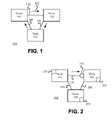
- FIG. 1is a block diagram of conventional network 100 .
- Conventional network 100includes nodes 110 , 120 , and 130 which are interconnected by communication channels 140 , 150 , and 160 .
- Nodes 110 , 120 , and 130may be layer 2 switches, Layer 2/Layer 3 switches, bridges or the like.
- Communication channels 140 , 150 , and 160may be unshielded twisted pair wire, coaxial cable, shielded twisted pair wire, fiber-optic cable, wireless connections, or other media suitable for interconnecting nodes.
- Network 100may use a layered architecture.
- a layered architectureis a hardware or software design in which the functions of one layer build upon the functions of a lower layer. Typically, each layer uses the services provided by the layer immediately below it and provides services to the layer above it.
- the well-known Open Systems Interconnection (OSI) reference model developed by the International Standardization Organization (ISO)is one exemplary model for layered architecture.
- Layer 2 of the OSI modelis responsible for creating, transmitting, and receiving digitally encoded packets. From the perspective of layer 2, nodes may be identified by their Media Access Control (MAC) addresses.
- MACMedia Access Control
- Forwardingis the process of passing a packet or message on to an intermediate or final destination. Forwarding may be performed by layer 2 hardware and software modules of network 100 (layer 2 forwarding).
- layer 2 forwardingThe fundamental properties of layer 2 forwarding are flooding, learning, and aging.
- Nodestypically make forwarding decisions based on a forwarding table.
- a forwarding tabletypically provides a listing of addresses with associated interfaces through which the address may be reached.
- the nodereads the source address (typically a MAC address) and updates the forwarding table with an entry indicating that the source address may be reached through the interface on which the packet was received.
- Learningrefers to the process of building a forwarding table based on information obtained from received packets.
- a nodewill discard forwarding table entries that have not been updated after a predetermined period. Aging refers to monitoring the age of forwarding table entries and discarding stale entries.
- the receiving nodemay also access the destination address of the received packet and compare that address to the forwarding table.
- the destination addresswill be one of three types: unicast, multicast, or broadcast. If the destination address is a unicast address and the node has an entry in its forwarding table that corresponds to that unicast address, then the node will forward the packet through the interface indicated by the entry in the forwarding table. If there is no entry corresponding to the unicast address then the node may forward the packet over all interfaces except the interface on which the packet was received.
- Floodingrefers to the process of forwarding a packet over all interfaces except an interface on which a packet was received. Packets having a multicast or broadcast destination address may also be flooded.
- network 100illustrates that the process of flooding may create a network loop if more than one path exists between any two nodes in network 100 .
- node 110may send packet 170 , having an unknown unicast address to node 120 .
- Node 120determines that packet 170 has an unknown unicast address and sends it over all available interfaces (e.g., over communication channel 150 ).
- Node 130similarly determines that packet 170 has an unknown unicast address and forwards the packet to node 110 .
- a network loopoccurs when a network provides alternate paths between nodes so that a flooded packet returns to the node from which it was sent.
- a redundancy protocolis a protocol that provides a mechanism to control and/or prevent network loops.
- redundancy protocolsinclude the IEEE 802.1D standard, 1998 Edition (ISO/IEC 15802-3:1998); the IEEE 802.1w-2001 standard, 2001 Edition; RFC 2338, “Virtual Router Redundancy Protocol,” S. Knight, et al, April 1998 (VRRP); and the Extreme Standby Redundancy Protocol (ESRP). Redundancy protocols are well known by those of ordinary skill in the art. For ease of discussion, nodes are herein described as having redundancy protocols rather than having implementations of redundancy protocols.
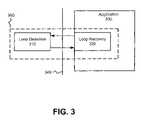
- FIG. 2is a block diagram of network 200 , illustrating how a redundancy protocol may limit the occurrence of a network loop.
- Network 200includes nodes and communication channels similar to those in network 100 and those nodes and communication channels are similarly numbered.
- Reference numerals 215 , 225 , and 235are instances of a redundancy protocol operating on nodes 210 , 220 , and 230 respectively. Redundancy protocols 215 , 225 , and 235 may communicate with each other by exchanging control packets. As is well known in the art, redundancy protocols 215 , 225 , and 235 may render one or more interfaces on nodes 210 , 220 , and 230 inactive to reduce the occurrence of network loops.
- interface 270 on node 220is inactive. Since the interface on node 220 is inactive there is only one active path between any two nodes in network 200 .
- the redundancy protocols operating on nodes 210 , 220 , and 230reduce the occurrence of network loops by attempting to ensure that there is only one active path between a source node and a destination node in network 200 .
- a problemmay occur, however, if there is a software failure or another anomaly in communication between the redundancy protocols operating on nodes 210 , 220 , and 230 .
- processing resources on node 210may be too busy to generate and process the control packets that direct node 220 to maintain interface 260 in an inactive state.
- node 220may bring interface 260 to an active state. Once interface 260 is in an active state, there will be more than one active path between each node in network 200 . Therefore, network 200 will likely experience network loops.
- FIG. 1is a block diagram illustrating selected elements of conventional network 100 .
- FIG. 2is a block diagram of network 200 , illustrating how a redundancy protocol may limit the occurrence of a network loop.
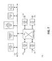
- FIG. 3is a block diagram illustrating the architecture of an embodiment of loop detection and recovery agent 300 .
- FIG. 4illustrates loop detection packet 400 implemented according to an embodiment of the invention.
- FIG. 5is a conceptual illustration showing the relationship between loop detection and recovery agent 300 and application 330 .
- FIG. 6is a state diagram illustrating selected states and state transitions for a node employing ESRP and the loop detection and recovery agent, according to an embodiment of the invention.
- FIG. 7is a block diagram of node 700 implemented according to an embodiment of the invention.
- FIG. 8is a flow diagram illustrating certain aspects of a method for loop detection and loop recovery according to an embodiment of the invention.
- Embodiments of the inventionare generally directed to a system and method for loop detection and recovery implemented in packet switched networks.
- a networked nodeis enhanced with a loop detection and recovery agent.
- the loop detection and recovery agentmay have a loop detection module and a loop recovery module.
- the loop detection modulemay operate independently from a redundancy protocol to determine whether a network loop exists. If a loop exists, the node may use the loop recovery module to recover from the loop.
- the loop recovery moduleis embedded in a redundancy protocol operating on the node.
- FIG. 3is a block diagram illustrating the architecture of an embodiment of loop detection and recovery agent 300 (hereinafter, agent 300 ).
- agent 300includes loop detection module 310 and loop recovery module 320 .
- loop detection module 310detects network loops independently of application 330 .
- Application 330may be a redundancy protocol, a management process, or any application capable of assisting loop recovery 320 in preventing and recovering from loops.
- loop recovery module 320is embedded in application 330 .
- Loop detection module 310uses loop detection packets to determine whether a network loop exists, in an embodiment of the invention.
- the loop detection packetsmay uniquely identify which node sent the packet.
- the originating nodeis identified through the source address of the loop detection packet.
- the loop detection packetsmay be formatted so that nodes other than the originating node process the packet as a multicast (or broadcast) packet.
- FIG. 4illustrates loop detection packet 400 implemented according to an embodiment of the invention.
- loop detection packet 400may be encoded as a layer 2 Ethernet multicast (or broadcast) packet.
- SASource address
- MACMedia Access Control
- DADestination address
- Embodiments of the inventionencode the loop detection packets as broadcast packets because broadcast packets are flooded throughout a network.
- Reference numeral 430shows that, in an embodiment of the invention, the Logical Link Control (LLC) Subnetwork Access Protocol (SNAP) header for loop detection packets may be encoded with the Extreme Discovery Protocol (EDP) LLC SNAP header.
- LLCLogical Link Control
- EDPExtreme Discovery Protocol
- Table 1provides a description of selected Type-Length-Value (TLV) fields for the illustrated embodiment of loop detection packet 400 .
- TLVType-Length-Value
- loop detection packet 400provides an indication of the packet's source port on the originating node.
- Reference numeral 440for example provides a field for the source Virtual Local Area Network (VLAN) port on the originating node. If the originating node receives packet 400 it can determine which port was the source port by accessing field 440 .
- VLANVirtual Local Area Network
- Packet 400also contains field 450 , in an embodiment of the invention.
- Field 450may be used to identify an application (e.g., application 330 ) which has registered with agent 300 .
- the identified applicationis the application in which the loop recovery module is embedded, in an embodiment of the invention.
- Agent 300may use the information obtained from field 450 to determine which application to notify if agent 300 detects a network loop. The process of an application registering with agent 300 is further described below in connection with Table 2.
- Loop detection module 310is independent of application 330 , in an embodiment of the invention, to increase the reliability of the node's loop detection and recovery capabilities.
- FIG. 5is a conceptual illustration showing the relationship between components of agent 300 and application 330 . As shown in FIG. 5 , loop detection module 310 is orthogonal to (e.g., independent of) application 330 . FIG. 5 also illustrates that, in an embodiment of the invention, loop recovery module 320 is embedded in application 330 . As is further described below, agent 300 may be implemented as executable content, control logic, firmware, or some combination thereof.
- agent 300performs a number of functions to support loop detection module 310 .
- agent 300may initialize data structures used by loop detection module 310 .
- Agent 300may also derive the source and destination addresses used by the loop detection packets.
- agent 300may program a node's forwarding tables so that loop detection packets that were sent from a node will be funneled to agent 300 when/if they return to the originating node.
- Agent 300monitors application 330 for requests to perform requested services, in an embodiment of the invention.
- Table 2shows a number of exemplary messages that agent 300 processes, in an embodiment of the invention.
- the register messageis typically the first message sent by an application to a loop detection and recovery agent.
- the Register messageinforms agent 300 that the application requests the services of agent 300 .
- the Unregister messagemay be used to inform agent 300 that the application no longer requires agent 300 's services.
- agent 300if an application sends the SendPeriodicLDPackets message to agent 300 , then agent 300 will periodically send loop detection packets until the application sends a StopPeriodicLDPackets message.
- the SendPeriodicLDPackets messageprovides a means for an application to specify a period for the frequency of sending loop detection packets, in an embodiment of the invention. If the application sets the period to zero, then agent 300 will send a single loop detection packet, in an embodiment of the invention.
- the third column of Table 2shows a number of Application Program Interfaces (APIs) used to support the described messages.
- Applicationsmay use the APIs to send messages to agent 300 .
- an applicationmay use a ClientID field to identify which application has sent the message.
- Agent 300may use the information in the ClientID field to determine which application should be notified if a loop is detected, in an embodiment of the invention.
- Agent 300may invoke a callback function to notify an application that a loop has been detected.
- the callback functionmay be specified by an application when it registers with agent 300 .
- Messages directing agent 300 to send loop detection packetsmay contain a list of ports from which the loop detection packets are to be sent.
- the APIs supporting the SendPeriodicLDPackets and StopPeriodicLDPacketsprovide a VportList field.
- the VportList fieldis used to identify the virtual ports from which loop detection packets should be sent, in an embodiment of the invention.
- agent 300may inform a registered application of the arrival of loop detection packets and on which ports (or virtual ports) the packets arrived, using the messages and APIs shown in Table 2.
- embodiments of agent 300may include both loop detection module 310 and a loop recovery module 320 .
- loop recovery module 320may be embedded in application 330 (e.g., in a redundancy protocol).
- application 330e.g., in a redundancy protocol
- One application that uses the services of agent 300 and may have an embedded loop recovery module 320is the Extreme Standby Redundancy Protocol (ESRP).
- ESRPExtreme Standby Redundancy Protocol
- the ESRPis similar to VRRP in that both protocols provide for a network to have one master node and a plurality of slave nodes.
- the master nodemaintains an active forwarding plane and directs the slave nodes to render their forwarding planes inactive. Master nodes may use control packets to maintain slave nodes in a slave state.
- Both ESRP and VRRPprovide redundancy by enabling a slave node to become a master node, if the current master node becomes inoperative.
- VRRPmerely provides redundancy at layer 3 while ESRP provides redundancy both at layer 3 and layer 2.
- ESRPis often employed in networks that support Virtual Local Area Networks (VLANs).
- VLANsVirtual Local Area Networks
- a slave nodemay incorrectly conclude that a master node is inoperative. For example, processing resources on a master node may be too busy to process control packets for a period of time. If slave nodes do not receive control packets from the master node for a predetermined period, they may conclude that the master node is inoperative. If a slave node incorrectly concludes that a master node is inoperative, then it may transition to a master node state and thereby introduce a second master node to a network.
- a networke.g., a LAN or VLAN having two or more master nodes may experience network loops.
- FIG. 6is a state diagram illustrating selected states and state transitions for a node employing ESRP and agent 300 , according to an embodiment of the invention.
- State diagram 600includes master state 610 , pre-master state 620 , and slave state 630 .
- a nodemay use agent 300 to prevent and detect network loops under two distinct conditions, in an embodiment of the invention.
- a nodemay use agent 300 to prevent and detect network loops, if it is a slave node and it concludes that the master node is inoperative. If a node is a slave node then it may be functioning in slave state 630 . While in slave state 630 , a slave node may periodically receive control packets from a master node. If a slave node does not receive control packets for a predetermined period of time, it may conclude that the master node is inoperative. As shown by reference numeral 640 , the slave node transitions to pre-master state 620 if it concludes that the master node is inoperative, in an embodiment of the invention.
- the nodeWhile in pre-master state 620 , the node may use agent 300 to periodically send loop detection packets.
- the nodemay remain in pre-master state 620 for a predetermined period of time while it determines whether any of the loop detection packets return to the originating node.
- Sending loop detection packets while in pre-master state 620allows the node to determine whether it will create any network loops if transitions to master state 610 .
- the nodemay wait a predetermined period of time for the return of the loop detection packets. If the loop detection packets do not return, then the node may transition to master state 610 , as shown by reference numeral 650 .
- the originating nodemay return to slave state 630 at reference numeral 660 .
- a node functioning in master state 610may also use the services of agent 300 .
- the master nodemay periodically send loop detection packets over one or more of its ports (e.g., LAN ports or VLAN ports). If the master node receives any of the sent loop detection packets on one of its ports, then the master node may conclude that a network loop exists.
- the master nodemay transition to slave state 630 , if it receives one (or more) of the loop detection packets that it sent, as shown by reference numeral 670 .
- Table 3shows a number of exemplary events and state transitions related to pre-master state 620 .
- Action 1corresponds to a message from an application directing agent 300 to send a loop detection packet over the specified ports and to start a pre-master timer.
- Action 2corresponds to a message to stop the pre-master timer in an embodiment of the invention.
- Action 3corresponds to a message from an application directing agent 300 to send a loop detection packet.
- FIG. 7is a block diagram of node 700 implemented according to an embodiment of the invention.
- Node 700may include: one or more control processors 710 , one or more management processors 720 , memory 730 , one or more Input/Output interfaces 740 , line cards 750 - 753 , switch fabric 760 , and loop detection and recovery agent 300 .
- the illustrated elementsmay be connected together through system interconnect 770 .
- One or more control processors 710 and one or more management processors 720may include a microprocessor, microcontroller, field programmable gate array (FPGA), application specific integrated circuit (ASIC), central processing unit (CPU), programmable logic device (PLD), and similar devices that access instructions from system storage (e.g., memory 730 ), decode them, and execute those instructions by performing arithmetic and logical operations.
- FPGAfield programmable gate array
- ASICapplication specific integrated circuit
- CPUcentral processing unit
- PLDprogrammable logic device
- one or more control processors 710 and one or more management processors 720are implemented with a common processor or processors.
- Loop detection and recovery agent 300enables node 700 to send loop detection packets (e.g., over communication channels 781 and 783 ) and to determine whether those loop detection packets return to node 700 (e.g., on communication channels 780 and 782 ).
- Loop detection and recovery agent 300may be executable content, control logic (e.g., ASIC, PLD, FPGA, etc.), firmware, or some combination thereof, in an embodiment of the invention. In embodiments of the invention in which loop detection and recovery agent 300 is executable content, it may be stored in memory 730 and executed by control processor 710 .
- Memory 730may encompass a wide variety of memory devices including read-only memory (ROM), erasable programmable read-only memory (EPROM), electrically erasable programmable read-only memory (EEPROM), random access memory (RAM), non-volatile random access memory (NVRAM), cache memory, flash memory, and other memory devices.
- Memory 730may also include one or more hard disks, floppy disks, ZIP disks, compact disks (e.g., CD-ROM), digital versatile/video disks (DVD), magnetic random access memory (MRAM) devices, and other system-readable media that store instructions and/or data.
- Memory 730may store program modules such as routines, programs, objects, images, data structures, program data, and other program modules that perform particular tasks or implement particular abstract data types that facilitate system use.
- Line cards 750 - 753provide an interface between communication channels 780 - 783 and other elements of node 700 .
- Line cards 750 - 753represent a broad range of interface elements capable of providing transmitting and/or receiving ports connecting node 700 to communication channels 780 - 783 .
- a person of ordinary skill in the artwill appreciate that the number of line cards in node 700 may be fewer or greater than the number shown in FIG. 7 .
- Switch fabric 760provides the interconnect architecture used to switch packets from incoming communication channels (e.g., 780 and 782 ) with outgoing communication channels (e.g., 781 and 783 ).
- Switch fabric 760represents a wide array of interconnect architectures capable of packet switching. Switch fabrics are well known in the art and, therefore, will not be further described except as to embodiments of the invention.
- One or more I/O interfaces 740may include a hard disk drive interface, a magnetic disk drive interface, an optical drive interface, a parallel port, serial controller or super I/O controller, serial port, universal serial bus (USB) port, a display device interface (e.g., video adapter), a network interface card (NIC), a sound card, modem, and the like.
- System interconnect 770permits communication between the various elements of node 700 .
- System interconnect 770may include a wide variety of signal lines including one or more of a memory bus, peripheral bus, local bus, host bus, bridge, optical, electrical, acoustical, and other propagated signal lines.
- FIG. 8the particular methods associated with embodiments of the invention are described in terms of computer software and hardware with reference to a flowchart.
- the methods to be performed by a loop detection and recovery agentmay constitute state machines or computer programs made up of computer-executable instructions. Describing the methods by reference to a flowchart enables one of ordinary skill in the art to develop such programs including such instructions to carry out the methods on suitably configured computing devices (e.g., one or more processors of a node) executing the instructions from computer-accessible media.
- the computer-executable instructionsmay be written in a computer programming language or may be embodied in firmware logic.
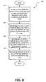
- FIG. 8is a flow diagram 800 illustrating certain aspects of a method for loop detection and loop recovery according to an embodiment of the invention.
- a nodee.g., node 700
- the loop detection packetis uniquely identified as a loop detection packet originating from the sending node, in an embodiment of the invention.
- the loop detection packetmay be a layer 2 broadcast packet having a source address that is a Media Access Control address of the originating node.
- the nodemay monitor one or more communication channels (e.g., communication channels 780 and 782 shown in FIG. 7 ) to determine whether one or more of the sent loop detection packet returns to the originating node.
- the nodemonitors incoming packets to determine whether an arriving packet has a source address that is the same as a MAC address of the node.
- the nodemay determine whether a network loop exists based, at least in part, on whether the node receives a loop detection packet that the node identifies as being one of the loop detection packets that it previously sent. In an embodiment of the invention, the node determines that a network loop exists, if the node receives a loop detection packet that it previously sent within a predetermined period of time.
- the nodemay recover from the network loop at process block 840 .
- the nodemay recover from the network loop by transitioning from a pre-master state (or a master state) to a slave state.
- the nodemay recover from the network loop by blocking one or more ports.
Landscapes
- Engineering & Computer Science (AREA)
- Computer Networks & Wireless Communication (AREA)
- Signal Processing (AREA)
- Physics & Mathematics (AREA)
- Algebra (AREA)
- General Physics & Mathematics (AREA)
- Mathematical Analysis (AREA)
- Mathematical Optimization (AREA)
- Mathematical Physics (AREA)
- Probability & Statistics with Applications (AREA)
- Pure & Applied Mathematics (AREA)
- Data Exchanges In Wide-Area Networks (AREA)
Abstract
Description
| TABLE 1 | |
| Type-Length-Value | |
| (TLV) Field | Description |
| Marker | A one byte field with value 0x99 |
| Type | A one byte field with value 0x0C |
| Length | A two byte field that holds the length of TLV |
| including the marker. | |
| Ver | A one byte field holding the Extreme Loop |
| Recovery Protocol (ELRP) version number | |
| Flag | A one byte field for holding flags |
| Reserved | A two byte reserved field |
| TABLE 2 | ||
| Application | ||
| Explanation | Program Interface | |
| Message | of Message | (API) to support message |
| Register | Request from an | ElrpRegClientAPI- |
| application to | (ClientID, Callback) | |
| register itself as a | ||
| client of | ||
| Unregister | Request from an | ElrpUnregClientAPI- |
| application to | (ClientID) | |
| remove itself from | ||
| the list of | ||
| 300's clients. | ||
| SendPeriodicLDPackets | This message is | ElrpStartSendAPI- |
| used by the | (ClientID, VportList, | |
| application to | period); // Period = 0 for | |
| request that agent | one shot send. | |
| 300 periodically | ||
| send a loop detect | ||
| packet. | ||
| SendOneShotLDPackets | This message is | |
| used by the | ||
| application to | ||
| request that | ||
| 300 send a single | ||
| loop detect packet. | ||
| StopPeriodicLDPackets | This message is | ElrpStopSendAPI- |
| used by the | (ClientID, VportList) | |
| application to | ||
| request that | ||
| 300 discontinue | ||
| sending periodic | ||
| loop detect packets. | ||
| TABLE 3 | ||
| STATES | ||
| EVENT | Neutral | Slave | Pre-Master | Master | |
| My | Action | 1, Pre- | |||
| are the Best | Master | ||||
| Loop | Slave | Action | 2, Slave | Slave | |
| Received | |||||
| Pre-Master | N/A | N/A | |||
| Timeout | Master | ||||
| My | Slave | Action | 2, Slave | Slave | |
| are no Longer | |||||
| the Best | |||||
| Parameters | |||||
| Action | 3, Pre- | ||||
| master | |||||
Claims (28)
Priority Applications (1)
| Application Number | Priority Date | Filing Date | Title |
|---|---|---|---|
| US10/393,113US7672228B1 (en) | 2003-03-19 | 2003-03-19 | System and method for network loop detection and recovery |
Applications Claiming Priority (1)
| Application Number | Priority Date | Filing Date | Title |
|---|---|---|---|
| US10/393,113US7672228B1 (en) | 2003-03-19 | 2003-03-19 | System and method for network loop detection and recovery |
Publications (1)
| Publication Number | Publication Date |
|---|---|
| US7672228B1true US7672228B1 (en) | 2010-03-02 |
Family
ID=41717657
Family Applications (1)
| Application Number | Title | Priority Date | Filing Date |
|---|---|---|---|
| US10/393,113Active2028-04-13US7672228B1 (en) | 2003-03-19 | 2003-03-19 | System and method for network loop detection and recovery |
Country Status (1)
| Country | Link |
|---|---|
| US (1) | US7672228B1 (en) |
Cited By (17)
| Publication number | Priority date | Publication date | Assignee | Title |
|---|---|---|---|---|
| US20050163115A1 (en)* | 2003-09-18 | 2005-07-28 | Sitaram Dontu | Distributed forwarding in virtual network devices |
| US20050198371A1 (en)* | 2004-02-19 | 2005-09-08 | Smith Michael R. | Interface bundles in virtual network devices |
| US20050243826A1 (en)* | 2004-04-28 | 2005-11-03 | Smith Michael R | Intelligent adjunct network device |
| US20060023718A1 (en)* | 2004-07-08 | 2006-02-02 | Christophe Joly | Network device architecture for centralized packet processing |
| US20060039384A1 (en)* | 2004-08-17 | 2006-02-23 | Sitaram Dontu | System and method for preventing erroneous link aggregation due to component relocation |
| US20080275975A1 (en)* | 2005-02-28 | 2008-11-06 | Blade Network Technologies, Inc. | Blade Server System with at Least One Rack-Switch Having Multiple Switches Interconnected and Configured for Management and Operation as a Single Virtual Switch |
| US20090086641A1 (en)* | 2004-06-30 | 2009-04-02 | Faisal Mushtaq | Method and Apparatus for Detecting Support for A Protocol Defining Supplemental Headers |
| US20100274894A1 (en)* | 2009-04-22 | 2010-10-28 | Hewlett Packard Development Company Lp | Router Method And System |
| US8208370B1 (en) | 2004-03-31 | 2012-06-26 | Cisco Technology, Inc. | Method and system for fast link failover |
| US8526427B1 (en) | 2003-10-21 | 2013-09-03 | Cisco Technology, Inc. | Port-based loadsharing for a satellite switch |
| US8615599B1 (en)* | 2006-03-31 | 2013-12-24 | Cisco Technology, Inc. | Method and apparatus for preventing loops in a network by controlling broadcasts |
| US8982711B2 (en) | 2012-04-20 | 2015-03-17 | Allied Telesis Holdings Kabushiki Kaisha | Self-healing communications network |
| US20160007285A1 (en)* | 2013-03-25 | 2016-01-07 | Davolink Inc. | Apparatus for supporting power-saving for wireless repeater and method thereof |
| JP2016116029A (en)* | 2014-12-12 | 2016-06-23 | 富士通株式会社 | Network monitoring method, relay device, and network monitoring system |
| US10567261B2 (en)* | 2015-11-26 | 2020-02-18 | Mitsubishi Electric Corporation | Relay device and communication network |
| US10959157B2 (en)* | 2017-08-17 | 2021-03-23 | Hype Labs Inc. | Systems and methods for wireless communication network loop detection |
| US20250300855A1 (en)* | 2024-03-21 | 2025-09-25 | Dell Products L.P. | Loop detecting and remediating system and method for a heterogeneous computing platform |
Citations (13)
| Publication number | Priority date | Publication date | Assignee | Title |
|---|---|---|---|---|
| US5563875A (en)* | 1995-07-10 | 1996-10-08 | International Business Machines Corporation | Wrap-around route testing in packet communications networks |
| US6023563A (en)* | 1996-08-20 | 2000-02-08 | Shani; Ron | Networking switch having the network presence of a bridge |
| US20030012164A1 (en)* | 2000-01-19 | 2003-01-16 | Yasuhiko Mizoguchi | Radio station and data packet transmitting/receiving method |
| US6580715B1 (en)* | 1998-05-04 | 2003-06-17 | Hewlett-Packard Development Company, L.P. | Load balancing switch protocols |
| US6587904B1 (en)* | 1999-11-05 | 2003-07-01 | Apple Computer, Inc. | Method and apparatus for preventing loops in a full-duplex bus |
| US6603740B1 (en)* | 1998-10-21 | 2003-08-05 | Koninklijke Philips Electronics N.V. | Local area network with a bridge terminal for transmitting data between a plurality of sub-networks and for loop detection |
| US20040008988A1 (en)* | 2001-10-01 | 2004-01-15 | Gerstal Ornan A. | Link discovery, verification, and failure isolation in an optical communication system |
| US6680903B1 (en)* | 1998-07-10 | 2004-01-20 | Matsushita Electric Industrial Co., Ltd. | Network system, network terminal, and method for specifying location of failure in network system |
| US6717922B2 (en)* | 2002-03-04 | 2004-04-06 | Foundry Networks, Inc. | Network configuration protocol and method for rapid traffic recovery and loop avoidance in ring topologies |
| US6765881B1 (en)* | 2000-12-06 | 2004-07-20 | Covad Communications Group, Inc. | Virtual L2TP/VPN tunnel network and spanning tree-based method for discovery of L2TP/VPN tunnels and other layer-2 services |
| US6810013B1 (en)* | 1997-04-15 | 2004-10-26 | Nokia Networks Oy | Path optimization in packet-based telecommunication network |
| US6810021B1 (en)* | 2000-01-14 | 2004-10-26 | Fujitsu Limited | Frame relay apparatus and method |
| US7126923B1 (en)* | 2002-05-28 | 2006-10-24 | Extreme Networks, Inc. | Method and system for inter-domain loop protection using a hierarchy of loop resolving protocols |
- 2003
- 2003-03-19USUS10/393,113patent/US7672228B1/enactiveActive
Patent Citations (13)
| Publication number | Priority date | Publication date | Assignee | Title |
|---|---|---|---|---|
| US5563875A (en)* | 1995-07-10 | 1996-10-08 | International Business Machines Corporation | Wrap-around route testing in packet communications networks |
| US6023563A (en)* | 1996-08-20 | 2000-02-08 | Shani; Ron | Networking switch having the network presence of a bridge |
| US6810013B1 (en)* | 1997-04-15 | 2004-10-26 | Nokia Networks Oy | Path optimization in packet-based telecommunication network |
| US6580715B1 (en)* | 1998-05-04 | 2003-06-17 | Hewlett-Packard Development Company, L.P. | Load balancing switch protocols |
| US6680903B1 (en)* | 1998-07-10 | 2004-01-20 | Matsushita Electric Industrial Co., Ltd. | Network system, network terminal, and method for specifying location of failure in network system |
| US6603740B1 (en)* | 1998-10-21 | 2003-08-05 | Koninklijke Philips Electronics N.V. | Local area network with a bridge terminal for transmitting data between a plurality of sub-networks and for loop detection |
| US6587904B1 (en)* | 1999-11-05 | 2003-07-01 | Apple Computer, Inc. | Method and apparatus for preventing loops in a full-duplex bus |
| US6810021B1 (en)* | 2000-01-14 | 2004-10-26 | Fujitsu Limited | Frame relay apparatus and method |
| US20030012164A1 (en)* | 2000-01-19 | 2003-01-16 | Yasuhiko Mizoguchi | Radio station and data packet transmitting/receiving method |
| US6765881B1 (en)* | 2000-12-06 | 2004-07-20 | Covad Communications Group, Inc. | Virtual L2TP/VPN tunnel network and spanning tree-based method for discovery of L2TP/VPN tunnels and other layer-2 services |
| US20040008988A1 (en)* | 2001-10-01 | 2004-01-15 | Gerstal Ornan A. | Link discovery, verification, and failure isolation in an optical communication system |
| US6717922B2 (en)* | 2002-03-04 | 2004-04-06 | Foundry Networks, Inc. | Network configuration protocol and method for rapid traffic recovery and loop avoidance in ring topologies |
| US7126923B1 (en)* | 2002-05-28 | 2006-10-24 | Extreme Networks, Inc. | Method and system for inter-domain loop protection using a hierarchy of loop resolving protocols |
Cited By (32)
| Publication number | Priority date | Publication date | Assignee | Title |
|---|---|---|---|---|
| US20050163115A1 (en)* | 2003-09-18 | 2005-07-28 | Sitaram Dontu | Distributed forwarding in virtual network devices |
| US7839843B2 (en) | 2003-09-18 | 2010-11-23 | Cisco Technology, Inc. | Distributed forwarding in virtual network devices |
| US8526427B1 (en) | 2003-10-21 | 2013-09-03 | Cisco Technology, Inc. | Port-based loadsharing for a satellite switch |
| US10069765B2 (en) | 2004-02-19 | 2018-09-04 | Cisco Technology, Inc. | Interface bundles in virtual network devices |
| US8990430B2 (en) | 2004-02-19 | 2015-03-24 | Cisco Technology, Inc. | Interface bundles in virtual network devices |
| US20050198371A1 (en)* | 2004-02-19 | 2005-09-08 | Smith Michael R. | Interface bundles in virtual network devices |
| US8208370B1 (en) | 2004-03-31 | 2012-06-26 | Cisco Technology, Inc. | Method and system for fast link failover |
| US9621419B2 (en) | 2004-04-28 | 2017-04-11 | Cisco Technology, Inc. | Determining when to switch to a standby intelligent adjunct network device |
| US8755382B2 (en) | 2004-04-28 | 2014-06-17 | Cisco Technology, Inc. | Intelligent adjunct network device |
| US20050243826A1 (en)* | 2004-04-28 | 2005-11-03 | Smith Michael R | Intelligent adjunct network device |
| US7889733B2 (en) | 2004-04-28 | 2011-02-15 | Cisco Technology, Inc. | Intelligent adjunct network device |
| US20110134923A1 (en)* | 2004-04-28 | 2011-06-09 | Smith Michael R | Intelligent Adjunct Network Device |
| US20090086641A1 (en)* | 2004-06-30 | 2009-04-02 | Faisal Mushtaq | Method and Apparatus for Detecting Support for A Protocol Defining Supplemental Headers |
| US8059652B2 (en) | 2004-06-30 | 2011-11-15 | Cisco Technology, Inc. | Method and apparatus for detecting support for a protocol defining supplemental headers |
| US7822025B1 (en) | 2004-07-08 | 2010-10-26 | Cisco Technology, Inc. | Network device architecture for centralized packet processing |
| US7808983B2 (en) | 2004-07-08 | 2010-10-05 | Cisco Technology, Inc. | Network device architecture for centralized packet processing |
| US20060023718A1 (en)* | 2004-07-08 | 2006-02-02 | Christophe Joly | Network device architecture for centralized packet processing |
| US8929207B1 (en) | 2004-07-08 | 2015-01-06 | Cisco Technology, Inc. | Network device architecture for centralized packet processing |
| US20060039384A1 (en)* | 2004-08-17 | 2006-02-23 | Sitaram Dontu | System and method for preventing erroneous link aggregation due to component relocation |
| US8730976B2 (en)* | 2004-08-17 | 2014-05-20 | Cisco Technology, Inc. | System and method for preventing erroneous link aggregation due to component relocation |
| US8194534B2 (en)* | 2005-02-28 | 2012-06-05 | International Business Machines Corporation | Blade server system with at least one rack-switch having multiple switches interconnected and configured for management and operation as a single virtual switch |
| US20080275975A1 (en)* | 2005-02-28 | 2008-11-06 | Blade Network Technologies, Inc. | Blade Server System with at Least One Rack-Switch Having Multiple Switches Interconnected and Configured for Management and Operation as a Single Virtual Switch |
| US8615599B1 (en)* | 2006-03-31 | 2013-12-24 | Cisco Technology, Inc. | Method and apparatus for preventing loops in a network by controlling broadcasts |
| US9088484B1 (en) | 2006-03-31 | 2015-07-21 | Cisco Technology, Inc. | Method and apparatus for preventing loops in a network by controlling broadcasts |
| US20100274894A1 (en)* | 2009-04-22 | 2010-10-28 | Hewlett Packard Development Company Lp | Router Method And System |
| US9397979B2 (en)* | 2009-04-22 | 2016-07-19 | Hewlett Packard Enterprise Development Lp | Router method and system |
| US8982711B2 (en) | 2012-04-20 | 2015-03-17 | Allied Telesis Holdings Kabushiki Kaisha | Self-healing communications network |
| US20160007285A1 (en)* | 2013-03-25 | 2016-01-07 | Davolink Inc. | Apparatus for supporting power-saving for wireless repeater and method thereof |
| JP2016116029A (en)* | 2014-12-12 | 2016-06-23 | 富士通株式会社 | Network monitoring method, relay device, and network monitoring system |
| US10567261B2 (en)* | 2015-11-26 | 2020-02-18 | Mitsubishi Electric Corporation | Relay device and communication network |
| US10959157B2 (en)* | 2017-08-17 | 2021-03-23 | Hype Labs Inc. | Systems and methods for wireless communication network loop detection |
| US20250300855A1 (en)* | 2024-03-21 | 2025-09-25 | Dell Products L.P. | Loop detecting and remediating system and method for a heterogeneous computing platform |
Similar Documents
| Publication | Publication Date | Title |
|---|---|---|
| US7672228B1 (en) | System and method for network loop detection and recovery | |
| US8520508B2 (en) | Spanning tree ring protocol | |
| US10284469B2 (en) | Progressive MAC address learning | |
| US9660939B2 (en) | Protection switching over a virtual link aggregation | |
| US7233991B2 (en) | Self-healing tree network | |
| US7929427B2 (en) | Ring rapid spanning tree protocol | |
| US8565069B2 (en) | Method of shrinking a data loss window in a packet network device | |
| US7027453B2 (en) | Spanning tree alternate routing bridge protocol | |
| US8411690B2 (en) | Preventing data traffic connectivity between endpoints of a network segment | |
| EP2533475B1 (en) | Method and system for host route reachability in packet transport network access ring | |
| US7941837B1 (en) | Layer two firewall with active-active high availability support | |
| US7903586B2 (en) | Ring rapid multiple spanning tree protocol system and method | |
| US8699380B2 (en) | Port table flushing in ethernet networks | |
| US20060294211A1 (en) | Forwarding table synchronization for virtual environments | |
| US12081458B2 (en) | Efficient convergence in network events | |
| US20170214609A1 (en) | Forwarding method and forwarding device | |
| CN108234234B (en) | Maintaining endpoint devices, methods for communicating, and computer-readable media | |
| US7233567B1 (en) | Apparatus and method for supporting multiple traffic redundancy mechanisms | |
| US7821920B2 (en) | Flushing processing unit and method of switching device in network using spanning tree protocol | |
| CN113938405A (en) | Data processing method and device | |
| US8976659B2 (en) | Intelligent layer-2 forwarding | |
| US8228823B2 (en) | Avoiding high-speed network partitions in favor of low-speed links | |
| CN1825832B (en) | Fast Ring Spanning Tree Protocol |
Legal Events
| Date | Code | Title | Description |
|---|---|---|---|
| AS | Assignment | Owner name:EXTREME NETWORKS,CALIFORNIA Free format text:ASSIGNMENT OF ASSIGNORS INTEREST;ASSIGNORS:SENEVIRATHNE, TISSA;JOSHI, VIDYADHAR;REEL/FRAME:013892/0116 Effective date:20030319 | |
| STCF | Information on status: patent grant | Free format text:PATENTED CASE | |
| FEPP | Fee payment procedure | Free format text:PAYER NUMBER DE-ASSIGNED (ORIGINAL EVENT CODE: RMPN); ENTITY STATUS OF PATENT OWNER: LARGE ENTITY Free format text:PAYOR NUMBER ASSIGNED (ORIGINAL EVENT CODE: ASPN); ENTITY STATUS OF PATENT OWNER: LARGE ENTITY | |
| FPAY | Fee payment | Year of fee payment:4 | |
| AS | Assignment | Owner name:SILICON VALLEY BANK, CALIFORNIA Free format text:SECURITY AGREEMENT;ASSIGNOR:EXTREME NETWORKS, INC.;REEL/FRAME:036189/0284 Effective date:20150724 | |
| AS | Assignment | Owner name:SILICON VALLEY BANK, CALIFORNIA Free format text:AMENDED AND RESTATED PATENT AND TRADEMARK SECURITY AGREEMENT;ASSIGNOR:EXTREME NETWORKS, INC.;REEL/FRAME:040521/0762 Effective date:20161028 | |
| AS | Assignment | Owner name:SILICON VALLEY BANK, CALIFORNIA Free format text:SECOND AMENDED AND RESTATED PATENT AND TRADEMARK SECURITY AGREEMENT;ASSIGNOR:EXTREME NETWORKS, INC.;REEL/FRAME:043200/0614 Effective date:20170714 | |
| MAFP | Maintenance fee payment | Free format text:PAYMENT OF MAINTENANCE FEE, 8TH YEAR, LARGE ENTITY (ORIGINAL EVENT CODE: M1552) Year of fee payment:8 | |
| AS | Assignment | Owner name:SILICON VALLEY BANK, CALIFORNIA Free format text:THIRD AMENDED AND RESTATED PATENT AND TRADEMARK SECURITY AGREEMENT;ASSIGNOR:EXTREME NETWORKS, INC.;REEL/FRAME:044639/0300 Effective date:20171027 | |
| AS | Assignment | Owner name:BANK OF MONTREAL, NEW YORK Free format text:SECURITY INTEREST;ASSIGNOR:EXTREME NETWORKS, INC.;REEL/FRAME:046050/0546 Effective date:20180501 Owner name:EXTREME NETWORKS, INC., CALIFORNIA Free format text:RELEASE BY SECURED PARTY;ASSIGNOR:SILICON VALLEY BANK;REEL/FRAME:046051/0775 Effective date:20180501 | |
| MAFP | Maintenance fee payment | Free format text:PAYMENT OF MAINTENANCE FEE, 12TH YEAR, LARGE ENTITY (ORIGINAL EVENT CODE: M1553); ENTITY STATUS OF PATENT OWNER: LARGE ENTITY Year of fee payment:12 | |
| AS | Assignment | Owner name:BANK OF MONTREAL, NEW YORK Free format text:AMENDED SECURITY AGREEMENT;ASSIGNORS:EXTREME NETWORKS, INC.;AEROHIVE NETWORKS, INC.;REEL/FRAME:064782/0971 Effective date:20230818 |