US7671482B2 - Hydrogen powered vehicle refueling strategy - Google Patents
Hydrogen powered vehicle refueling strategyDownload PDFInfo
- Publication number
- US7671482B2 US7671482B2US11/670,756US67075607AUS7671482B2US 7671482 B2US7671482 B2US 7671482B2US 67075607 AUS67075607 AUS 67075607AUS 7671482 B2US7671482 B2US 7671482B2
- Authority
- US
- United States
- Prior art keywords
- refueling
- vehicle
- sensor
- control system
- fuel
- Prior art date
- Legal status (The legal status is an assumption and is not a legal conclusion. Google has not performed a legal analysis and makes no representation as to the accuracy of the status listed.)
- Active, expires
Links
- UFHFLCQGNIYNRP-UHFFFAOYSA-NHydrogenChemical compound[H][H]UFHFLCQGNIYNRP-UHFFFAOYSA-N0.000titleclaimsabstractdescription25
- 229910052739hydrogenInorganic materials0.000titleclaimsabstractdescription25
- 239000001257hydrogenSubstances0.000titleclaimsabstractdescription25
- 239000000446fuelSubstances0.000claimsabstractdescription66
- 238000000034methodMethods0.000claimsabstractdescription35
- 239000002828fuel tankSubstances0.000claimsdescription28
- 238000010586diagramMethods0.000description1
- 239000012530fluidSubstances0.000description1
- 238000012986modificationMethods0.000description1
- 230000004048modificationEffects0.000description1
- 230000000630rising effectEffects0.000description1
- 230000002747voluntary effectEffects0.000description1
Images

Classifications
- B—PERFORMING OPERATIONS; TRANSPORTING
- B60—VEHICLES IN GENERAL
- B60L—PROPULSION OF ELECTRICALLY-PROPELLED VEHICLES; SUPPLYING ELECTRIC POWER FOR AUXILIARY EQUIPMENT OF ELECTRICALLY-PROPELLED VEHICLES; ELECTRODYNAMIC BRAKE SYSTEMS FOR VEHICLES IN GENERAL; MAGNETIC SUSPENSION OR LEVITATION FOR VEHICLES; MONITORING OPERATING VARIABLES OF ELECTRICALLY-PROPELLED VEHICLES; ELECTRIC SAFETY DEVICES FOR ELECTRICALLY-PROPELLED VEHICLES
- B60L58/00—Methods or circuit arrangements for monitoring or controlling batteries or fuel cells, specially adapted for electric vehicles
- B60L58/30—Methods or circuit arrangements for monitoring or controlling batteries or fuel cells, specially adapted for electric vehicles for monitoring or controlling fuel cells
- H—ELECTRICITY
- H01—ELECTRIC ELEMENTS
- H01M—PROCESSES OR MEANS, e.g. BATTERIES, FOR THE DIRECT CONVERSION OF CHEMICAL ENERGY INTO ELECTRICAL ENERGY
- H01M2250/00—Fuel cells for particular applications; Specific features of fuel cell system
- H01M2250/20—Fuel cells in motive systems, e.g. vehicle, ship, plane
- Y—GENERAL TAGGING OF NEW TECHNOLOGICAL DEVELOPMENTS; GENERAL TAGGING OF CROSS-SECTIONAL TECHNOLOGIES SPANNING OVER SEVERAL SECTIONS OF THE IPC; TECHNICAL SUBJECTS COVERED BY FORMER USPC CROSS-REFERENCE ART COLLECTIONS [XRACs] AND DIGESTS
- Y02—TECHNOLOGIES OR APPLICATIONS FOR MITIGATION OR ADAPTATION AGAINST CLIMATE CHANGE
- Y02E—REDUCTION OF GREENHOUSE GAS [GHG] EMISSIONS, RELATED TO ENERGY GENERATION, TRANSMISSION OR DISTRIBUTION
- Y02E60/00—Enabling technologies; Technologies with a potential or indirect contribution to GHG emissions mitigation
- Y02E60/30—Hydrogen technology
- Y02E60/50—Fuel cells
- Y—GENERAL TAGGING OF NEW TECHNOLOGICAL DEVELOPMENTS; GENERAL TAGGING OF CROSS-SECTIONAL TECHNOLOGIES SPANNING OVER SEVERAL SECTIONS OF THE IPC; TECHNICAL SUBJECTS COVERED BY FORMER USPC CROSS-REFERENCE ART COLLECTIONS [XRACs] AND DIGESTS
- Y02—TECHNOLOGIES OR APPLICATIONS FOR MITIGATION OR ADAPTATION AGAINST CLIMATE CHANGE
- Y02T—CLIMATE CHANGE MITIGATION TECHNOLOGIES RELATED TO TRANSPORTATION
- Y02T90/00—Enabling technologies or technologies with a potential or indirect contribution to GHG emissions mitigation
- Y02T90/40—Application of hydrogen technology to transportation, e.g. using fuel cells
Definitions
- This inventionrelates to a method of operation of a hydrogen fuel cell powered vehicle. More particularly, this invention is directed to a method of refueling a hydrogen fuel cell powered vehicle.
- Vehicle fueling stationstypically require that vehicles be turned off during refueling to minimize the risks of vehicle damage associated with vehicle operation during the refueling process. Ensuring vehicles are not operated during refueling is primarily accomplished through enforcement by fueling station attendants, or is a voluntary process depending upon the cooperation of the vehicle operator.
- a hydrogen fueling systemthat automatically disables vehicle systems when refueling is occurring, resets the vehicle systems after the refueling is complete, and determines if a faulty refueling event has been detected has surprisingly been discovered.
- the method of refueling a hydrogen fuel cell powered vehicleincludes the steps of providing a traction drive system, a control system in electrical communication with the traction drive system, and at least one refueling sensor in electrical communication with the control system; determining the vehicle is refueling using the refueling sensors; communicating a vehicle refueling signal from the refueling sensors to the control system; and disabling the traction drive system using the control system when a vehicle refueling signal is received.
- the method of refueling a hydrogen fuel cell powered vehicleincludes the steps of providing a traction drive system, a control system in electrical communication with the traction drive system, at least one fuel inlet sensor in electrical communication with the control system, and at least one fuel tank sensor in electrical communication with the control system; determining vehicle refueling using the fuel inlet sensor; determining vehicle refueling using the fuel tank sensor; communicating a first vehicle refueling signal from the fuel inlet sensor and a second refueling signal from the fuel tank sensor to the control system; disabling the traction drive system using the control system when a vehicle refueling signal is received; and re-enabling the traction drive system using the control system when the refueling is complete.
- the method of refueling a hydrogen fuel cell powered vehicleincludes the steps of providing a traction drive system, a control system in electrical communication with the traction drive system, at least one fuel inlet sensor in electrical communication with the control system, and at least one fuel tank sensor in electrical communication with the control system; determining vehicle refueling using the fuel inlet sensor; determining vehicle refueling using the fuel tank sensor; communicating a first vehicle refueling signal from the fuel inlet sensor and a second refueling signal from the fuel tank sensor to the control system; determining a faulty refueling signal when the first refueling signal and the second refueling signal do not both communicate a refueling signal to the control system within, a predetermined time period; disabling the traction drive system using the control system when the vehicle refueling signal received is not faulty; and re-enabling the traction drive system using the control system when the refueling is complete.
- FIG. 1is a schematic illustration of a hydrogen powered vehicle with refueling system components of the present invention
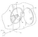
- FIG. 2shows a fragmentary perspective view of a fuel door in the open position and showing the control systems schematically according to the embodiment of the invention shown in FIG. 1 ;
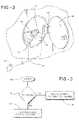
- FIG. 3is a flow diagram illustrating a method of operation of the present invention.
- the hydrogen powered vehicle refueling strategyis provided in a vehicle 2 , as shown in FIG. 1 .
- the vehicle 2includes a traction drive system or vehicle system 10 . It is understood that other vehicle systems can be used as desired.
- a plurality of wheels 4are mechanically coupled to the traction drive system 10 .
- the traction drive system 10is electrically linked to a control system 16 via a connection 12 .
- the connection 12may be any conventional means of electrical communication.
- a fuel inlet 24is formed in the vehicle 2 and is in fluid communication with a fuel tank 20 .
- the fuel inlet 24includes at least one fuel inlet sensor, such as a fuel door switch 40 , and a fuel nozzle sensor 42 , for example, as clearly shown in FIG. 2 .
- the fuel inlet sensoris in electrical communication with the control system 16 via an electrical connection 14 .
- the fuel tank 20includes at least one fuel tank sensor, such as a temperature sensor 26 , and a pressure sensor 27 .
- the fuel tank sensoris in electrical communication with the control system 16 via an electrical connection 18 .
- the vehicle 2may include other sensors without departing from the scope of this invention.
- a fuel inlet door 34is pivotally connected to the fuel inlet 24 via a hinge 32 .
- An aperture 30is formed in the fuel inlet 24 .
- the aperture 30is adapted to receive a hydrogen fuel pump nozzle (not shown).
- the fuel door switch 40is disposed adjacent the fuel inlet 24 to sense when the fuel door 34 is in an open or closed position.
- the fuel inlet sensor 42is disposed near the aperture 30 to sense when a hydrogen fuel pump nozzle is inserted in the aperture 30 .
- the fuel door switch 40 and the fuel nozzle sensor 42generate and transmit a refueling signal to the control system 16 via the connection 14 .
- Other sensorsmay be used without departing from the scope of this invention.
- the traction drive system 10controls whether power generated by a fuel cell is sent to the vehicles wheels 4 and/or whether the traction drive system converts the available power to mechanical work.
- the control system 16selectively controls the traction drive system 10 via the communication 12 .
- the control system 16disables the traction drive system 10 when vehicle refueling occurs (Y at 52 ), shown in FIG. 3 . Disabling the traction drive system 10 prevents a user from driving away while the vehicle 2 is being refueled.
- the control system 16enables the traction drive system 10 when refueling is not occurring (N at 52 ). Additionally, it may be desirable for the control system 16 to disable other vehicle 2 systems, such as the fuel cell power system (not shown), when refueling is detected.
- refuelingis communicated to the control system 16 in several methods.
- a first refueling signalis communicated to the control system 16 from the at least one fuel inlet sensor via the connection 14 . It may be desirable to communicate the first refueling signal from the fuel nozzle sensor 42 .
- the fuel nozzle sensor 42When a hydrogen fuel pump nozzle is detected in the aperture 30 the fuel nozzle sensor 42 generates and transmits a signal that refueling is occurring (Y at 52 ) to the control system 16 .
- the fuel door switch 40When the fuel door 34 is an open position the fuel door switch 40 generates and transmits a signal that refueling is occurring (Y at 52 ) to the control system 16 .
- the fuel door switch 40 , and the fuel inlet sensor 42may be contact sensors such as micro-switches, or non-contact sensors such as proximity sensors. Additionally, other types of sensors or combinations of sensors may be used without departing from the scope
- a second refueling signalis sent to the control system 16 from the at least one fuel tank sensor via the connection 18 . It may be desirable to send the second refueling signal from the temperature sensor 26 . When a sudden drop in fuel tank 20 temperature is detected the temperature sensor 26 generates and transmits a signal to the control system 16 . It may be further desirable to communicate the second refueling signal from the pressure sensor 27 . When rapidly rising fuel tank 20 pressure is detected, the pressure sensor 27 generates and transmits a signal to the control system 16 . Additionally, other types of sensors may be used without departing from the scope of this invention.
- control system 16may be desirable to use both the first refueling signal and the second refueling signal together in order to determine whether a faulty refueling signal has been communicated to the control system 16 . For example, if the control system 16 receives the first refueling signal from the fuel door switch 40 , and does not receive a second refueling signal from the pressure sensor 27 within a predetermined time period, the control system 16 could determine that the fuel door switch 40 sent a faulty signal and the system may be re-enabled because refueling is not taking place.
- the control system 16determines that refueling is complete or not occurring (N at 52 ) the traction drive system 10 is re-enabled. It may be desirable to implement a time delay before re-enabling the traction drive system 10 in order to ensure that the refueling process is complete.
Landscapes
- Engineering & Computer Science (AREA)
- Life Sciences & Earth Sciences (AREA)
- Sustainable Development (AREA)
- Sustainable Energy (AREA)
- Power Engineering (AREA)
- Transportation (AREA)
- Mechanical Engineering (AREA)
- Fuel Cell (AREA)
- Electric Propulsion And Braking For Vehicles (AREA)
Abstract
Description
Claims (20)
Priority Applications (1)
| Application Number | Priority Date | Filing Date | Title |
|---|---|---|---|
| US11/670,756US7671482B2 (en) | 2007-02-02 | 2007-02-02 | Hydrogen powered vehicle refueling strategy |
Applications Claiming Priority (1)
| Application Number | Priority Date | Filing Date | Title |
|---|---|---|---|
| US11/670,756US7671482B2 (en) | 2007-02-02 | 2007-02-02 | Hydrogen powered vehicle refueling strategy |
Publications (2)
| Publication Number | Publication Date |
|---|---|
| US20080185912A1 US20080185912A1 (en) | 2008-08-07 |
| US7671482B2true US7671482B2 (en) | 2010-03-02 |
Family
ID=39675556
Family Applications (1)
| Application Number | Title | Priority Date | Filing Date |
|---|---|---|---|
| US11/670,756Active2028-03-16US7671482B2 (en) | 2007-02-02 | 2007-02-02 | Hydrogen powered vehicle refueling strategy |
Country Status (1)
| Country | Link |
|---|---|
| US (1) | US7671482B2 (en) |
Cited By (21)
| Publication number | Priority date | Publication date | Assignee | Title |
|---|---|---|---|---|
| US20090216400A1 (en)* | 2008-02-22 | 2009-08-27 | Gm Global Technology Operations, Inc. | Fuel door sensor diagnostic systems and methods |
| US20100252349A1 (en)* | 2009-04-02 | 2010-10-07 | Marshall Excelsior Company | Nozzle actuated system for disabling a vehicle |
| US20100252352A1 (en)* | 2009-04-02 | 2010-10-07 | Marshall Excelsior Company | System and method for disabling a vehicle |
| US20100252565A1 (en)* | 2009-04-02 | 2010-10-07 | Walter Pipp | Access port cover |
| US20120305710A1 (en)* | 2011-06-03 | 2012-12-06 | Eads Construcciones Aeronauticas, S.A. | System for detecting the status of a tube for fuel transfer |
| US20130074985A1 (en)* | 2011-09-28 | 2013-03-28 | Tesla Motors, Inc. | Vehicle Port Door with Wirelessly Actuated Unlatching Assembly |
| US20130246866A1 (en)* | 2012-03-14 | 2013-09-19 | GM Global Technology Operations LLC | System and method for verifying the integrity of a safety-critical vehicle control system |
| US8662235B2 (en)* | 2012-05-03 | 2014-03-04 | Daniel McNicholas | Compressed natural gas vehicle safety system and method |
| US8720968B2 (en) | 2011-09-28 | 2014-05-13 | Tesla Motors, Inc. | Charge port door with electromagnetic latching assembly |
| US8783303B2 (en) | 2010-04-21 | 2014-07-22 | Ryan HARTY | Method and system for tank refilling |
| US9022080B2 (en) | 2012-02-08 | 2015-05-05 | Honda Motor Co., Ltd. | Communication device activated by fuel door |
| US9207661B2 (en) | 2007-07-20 | 2015-12-08 | GM Global Technology Operations LLC | Dual core architecture of a control module of an engine |
| US9212783B2 (en) | 2010-04-21 | 2015-12-15 | Honda Motor Co., Ltd. | Method and system for tank refilling |
| US9347612B2 (en) | 2010-04-21 | 2016-05-24 | Honda Motor Co., Ltd. | Method and system for tank refilling using active fueling speed control |
| US9347614B2 (en) | 2010-04-21 | 2016-05-24 | Honda Motor Co., Ltd. | Method and system for tank refilling using active fueling speed control |
| US9376012B2 (en)* | 2014-10-13 | 2016-06-28 | Srg Global, Inc. | Vehicle fuel filler system seal |
| US9605804B2 (en) | 2010-04-21 | 2017-03-28 | Honda Motor Co., Ltd. | Method and system for tank refilling using active fueling speed control |
| US10040680B2 (en) | 2012-05-03 | 2018-08-07 | Daniel McNicholas | Compressed natural gas vehicle safety system and method |
| US10077998B2 (en) | 2015-09-14 | 2018-09-18 | Honda Motor Co., Ltd. | Hydrogen fueling with integrity checks |
| US11313514B2 (en) | 2018-12-04 | 2022-04-26 | Honda Motor Co., Ltd. | Method and system for tank refueling using dispenser and nozzle readings |
| US11339926B2 (en) | 2018-12-05 | 2022-05-24 | Honda Motor Co., Ltd. | Methods and systems for improving hydrogen refueling |
Families Citing this family (9)
| Publication number | Priority date | Publication date | Assignee | Title |
|---|---|---|---|---|
| JP2011156896A (en)* | 2010-01-29 | 2011-08-18 | Toyota Motor Corp | Vehicle |
| US9673462B2 (en)* | 2011-10-31 | 2017-06-06 | Plug Power Inc. | Fuel cell-vehicle communications systems and methods |
| JP6237690B2 (en)* | 2015-04-22 | 2017-11-29 | トヨタ自動車株式会社 | Fuel cell system |
| US9834205B1 (en)* | 2016-11-21 | 2017-12-05 | Ford Global Technologies, Llc | Hybrid vehicle evaporation systems |
| DE102017202342A1 (en) | 2017-02-14 | 2018-08-16 | Bayerische Motoren Werke Aktiengesellschaft | Vehicle and method for demobilization of the vehicle when refueling |
| KR102463419B1 (en)* | 2017-10-13 | 2022-11-03 | 현대자동차주식회사 | System and method for sensing fuel charge state of fuel cell electric vehicle |
| DE102017218672A1 (en)* | 2017-10-19 | 2019-04-25 | Bayerische Motoren Werke Aktiengesellschaft | A method for controlling an emergency release of a cover of a media supply device in a motor vehicle |
| DE102021209445B4 (en) | 2021-08-27 | 2023-11-09 | Volkswagen Aktiengesellschaft | Method for checking a connection device of a motor vehicle and control device for a motor vehicle |
| US12292162B2 (en)* | 2022-03-22 | 2025-05-06 | Toyota Motor Engineering & Manufacturing North America, Inc. | Hydrogen refueling IR interference shield |
Citations (9)
| Publication number | Priority date | Publication date | Assignee | Title |
|---|---|---|---|---|
| US3572305A (en) | 1970-05-04 | 1971-03-23 | Edward L Moragne | Engine ignition interrupting safety device for fuel tank covers |
| US5720327A (en)* | 1996-05-24 | 1998-02-24 | Foster, Jr.; James C. | Vehicle safety fueling system |
| US6011484A (en) | 1996-05-23 | 2000-01-04 | Bayerische Motoren Werke Aktiengesellschaft | System and method for controlling refueling of a motor vehicle |
| EP1116913A2 (en) | 2000-01-06 | 2001-07-18 | General Motors Corporation | Method and apparatus for refueling a hydrogen tank for a fuel cell |
| US6712171B2 (en) | 2001-10-02 | 2004-03-30 | Honda Giken Kogyo Kabushiki Kaisha | Refueling safety switch |
| US6964821B2 (en) | 2000-06-08 | 2005-11-15 | Toyota Jidosha Kabushiki Kaisha | Fuel cell fuel supply system and mobile body |
| US20060011164A1 (en) | 2004-07-14 | 2006-01-19 | Kropinski Michael A | Vehicle fueling arrangement |
| US7051831B2 (en)* | 2001-08-24 | 2006-05-30 | Ford Global Technologies, Llc | Method and apparatus for maintaining a connection between a vehicle and a fuel source |
| US7171989B2 (en)* | 2003-10-31 | 2007-02-06 | Cellex Power Products, Inc. | Fuel dispensing system and method |
- 2007
- 2007-02-02USUS11/670,756patent/US7671482B2/enactiveActive
Patent Citations (9)
| Publication number | Priority date | Publication date | Assignee | Title |
|---|---|---|---|---|
| US3572305A (en) | 1970-05-04 | 1971-03-23 | Edward L Moragne | Engine ignition interrupting safety device for fuel tank covers |
| US6011484A (en) | 1996-05-23 | 2000-01-04 | Bayerische Motoren Werke Aktiengesellschaft | System and method for controlling refueling of a motor vehicle |
| US5720327A (en)* | 1996-05-24 | 1998-02-24 | Foster, Jr.; James C. | Vehicle safety fueling system |
| EP1116913A2 (en) | 2000-01-06 | 2001-07-18 | General Motors Corporation | Method and apparatus for refueling a hydrogen tank for a fuel cell |
| US6964821B2 (en) | 2000-06-08 | 2005-11-15 | Toyota Jidosha Kabushiki Kaisha | Fuel cell fuel supply system and mobile body |
| US7051831B2 (en)* | 2001-08-24 | 2006-05-30 | Ford Global Technologies, Llc | Method and apparatus for maintaining a connection between a vehicle and a fuel source |
| US6712171B2 (en) | 2001-10-02 | 2004-03-30 | Honda Giken Kogyo Kabushiki Kaisha | Refueling safety switch |
| US7171989B2 (en)* | 2003-10-31 | 2007-02-06 | Cellex Power Products, Inc. | Fuel dispensing system and method |
| US20060011164A1 (en) | 2004-07-14 | 2006-01-19 | Kropinski Michael A | Vehicle fueling arrangement |
Cited By (39)
| Publication number | Priority date | Publication date | Assignee | Title |
|---|---|---|---|---|
| US9207661B2 (en) | 2007-07-20 | 2015-12-08 | GM Global Technology Operations LLC | Dual core architecture of a control module of an engine |
| US8000856B2 (en)* | 2008-02-22 | 2011-08-16 | GM Global Technology Operations LLC | Fuel door sensor diagnostic systems and methods |
| US20090216400A1 (en)* | 2008-02-22 | 2009-08-27 | Gm Global Technology Operations, Inc. | Fuel door sensor diagnostic systems and methods |
| US8905458B2 (en)* | 2009-04-02 | 2014-12-09 | A. Raymond Et Cie | Access port cover |
| US20100252349A1 (en)* | 2009-04-02 | 2010-10-07 | Marshall Excelsior Company | Nozzle actuated system for disabling a vehicle |
| US20100252352A1 (en)* | 2009-04-02 | 2010-10-07 | Marshall Excelsior Company | System and method for disabling a vehicle |
| US20100252565A1 (en)* | 2009-04-02 | 2010-10-07 | Walter Pipp | Access port cover |
| US8132639B2 (en)* | 2009-04-02 | 2012-03-13 | Marshall Excelsior Company | Nozzle actuated system for disabling a vehicle |
| US8210306B2 (en)* | 2009-04-02 | 2012-07-03 | Marshall Excelsior Company | System and method for disabling a vehicle |
| US9605804B2 (en) | 2010-04-21 | 2017-03-28 | Honda Motor Co., Ltd. | Method and system for tank refilling using active fueling speed control |
| US8783303B2 (en) | 2010-04-21 | 2014-07-22 | Ryan HARTY | Method and system for tank refilling |
| US9222620B2 (en) | 2010-04-21 | 2015-12-29 | Honda Motor Co., Ltd. | Method and system for tank refilling |
| US9212783B2 (en) | 2010-04-21 | 2015-12-15 | Honda Motor Co., Ltd. | Method and system for tank refilling |
| US9347614B2 (en) | 2010-04-21 | 2016-05-24 | Honda Motor Co., Ltd. | Method and system for tank refilling using active fueling speed control |
| US9347612B2 (en) | 2010-04-21 | 2016-05-24 | Honda Motor Co., Ltd. | Method and system for tank refilling using active fueling speed control |
| US9193471B2 (en)* | 2011-06-03 | 2015-11-24 | Eads Construcciones Aeronauticas, S.A. | System for detecting the status of a tube for fuel transfer |
| US20120305710A1 (en)* | 2011-06-03 | 2012-12-06 | Eads Construcciones Aeronauticas, S.A. | System for detecting the status of a tube for fuel transfer |
| US20130074411A1 (en)* | 2011-09-28 | 2013-03-28 | Tesla Motors, Inc. | Fuel Coupler with Wireless Port Door Unlatching Actuator |
| US20130074985A1 (en)* | 2011-09-28 | 2013-03-28 | Tesla Motors, Inc. | Vehicle Port Door with Wirelessly Actuated Unlatching Assembly |
| US8720968B2 (en) | 2011-09-28 | 2014-05-13 | Tesla Motors, Inc. | Charge port door with electromagnetic latching assembly |
| US8627860B2 (en)* | 2011-09-28 | 2014-01-14 | Tesla Motors, Inc. | Fuel coupler with wireless port door unlatching actuator |
| US8539990B2 (en)* | 2011-09-28 | 2013-09-24 | Tesla Motors, Inc. | Vehicle port door with wirelessly actuated unlatching assembly |
| US9022080B2 (en) | 2012-02-08 | 2015-05-05 | Honda Motor Co., Ltd. | Communication device activated by fuel door |
| US9058419B2 (en)* | 2012-03-14 | 2015-06-16 | GM Global Technology Operations LLC | System and method for verifying the integrity of a safety-critical vehicle control system |
| US20130246866A1 (en)* | 2012-03-14 | 2013-09-19 | GM Global Technology Operations LLC | System and method for verifying the integrity of a safety-critical vehicle control system |
| US11001210B2 (en)* | 2012-05-03 | 2021-05-11 | Daniel McNicholas | Compressed natural gas vehicle safety system and method |
| US12409794B2 (en) | 2012-05-03 | 2025-09-09 | Daniel McNicholas | Compressed natural gas vehicle safety system and method |
| US9434329B2 (en) | 2012-05-03 | 2016-09-06 | Daniel McNicholas | Compressed natural gas vehicle safety system and method |
| US8662235B2 (en)* | 2012-05-03 | 2014-03-04 | Daniel McNicholas | Compressed natural gas vehicle safety system and method |
| US11524639B2 (en) | 2012-05-03 | 2022-12-13 | Daniel McNicholas | Compressed natural gas vehicle safety system and method |
| US9919663B2 (en) | 2012-05-03 | 2018-03-20 | Daniel McNicholas | Compressed natural gas vehicle safety system and method |
| US10040680B2 (en) | 2012-05-03 | 2018-08-07 | Daniel McNicholas | Compressed natural gas vehicle safety system and method |
| US20160263994A1 (en)* | 2014-10-13 | 2016-09-15 | Srg Global, Inc. | Vehicle Fuel Filler System Seal |
| US9862266B2 (en)* | 2014-10-13 | 2018-01-09 | Srg Global, Inc. | Vehicle fuel filler system seal |
| US9376012B2 (en)* | 2014-10-13 | 2016-06-28 | Srg Global, Inc. | Vehicle fuel filler system seal |
| US10782173B2 (en) | 2015-09-14 | 2020-09-22 | Honda Motor Co., Ltd. | Hydrogen fueling with integrity checks |
| US10077998B2 (en) | 2015-09-14 | 2018-09-18 | Honda Motor Co., Ltd. | Hydrogen fueling with integrity checks |
| US11313514B2 (en) | 2018-12-04 | 2022-04-26 | Honda Motor Co., Ltd. | Method and system for tank refueling using dispenser and nozzle readings |
| US11339926B2 (en) | 2018-12-05 | 2022-05-24 | Honda Motor Co., Ltd. | Methods and systems for improving hydrogen refueling |
Also Published As
| Publication number | Publication date |
|---|---|
| US20080185912A1 (en) | 2008-08-07 |
Similar Documents
| Publication | Publication Date | Title |
|---|---|---|
| US7671482B2 (en) | Hydrogen powered vehicle refueling strategy | |
| US9022080B2 (en) | Communication device activated by fuel door | |
| US9428182B2 (en) | Vehicle with fuel cells mounted thereon and control method of the vehicle | |
| US8720469B2 (en) | Electronic flow sensor | |
| US8942873B2 (en) | Safety control system and method for hydrogen charging of fuel-cell vehicle | |
| US8360117B2 (en) | System and method for monitoring a ground connection | |
| US10059225B2 (en) | Fuel cell vehicle and control method for fuel cell vehicle | |
| US10655590B2 (en) | Vehicle | |
| US20140152255A1 (en) | Method and Apparatus for Preventing Simultaneous Charging and Fueling of a Plug-In Hybrid Electric Vehicle | |
| US20180105041A1 (en) | Method and device for a high-voltage energy system of a vehicle | |
| CN107542584A (en) | Liquid level for vehicle reservoir indicates | |
| KR20250040599A (en) | Charging control apparatus for electric vehicle and charging apparatus comprising the same | |
| JP2012076713A (en) | Vehicle, and filling state-reporting apparatus | |
| JP3736414B2 (en) | VEHICLE FUEL DEVICE, FUEL FILLING EQUIPMENT, AND FUEL FILLING SYSTEM | |
| WO2011101004A1 (en) | Tank device for a fuel tank of a fuel cell vehicle, and tank system | |
| KR20130002661A (en) | System for checking state of automobile and control method thereof | |
| US20160311340A1 (en) | Fuel cell system | |
| JP2021028504A (en) | Hydrogen filling system | |
| US20020162601A1 (en) | Safety system for fueling vehicle | |
| US20240189637A1 (en) | Cooperative fire extinguishing system for vehicle | |
| US11480300B1 (en) | Refueling adapter for an alternative fuel vehicle and method for refueling | |
| CN105270323A (en) | Electronic chip anti-theft control system applied to pure electric car and anti-theft method of the anti-theft control system | |
| CN114987206A (en) | Vehicle-mounted hydrogen supply control system and hydrogen supply monitoring system | |
| EP1526276B1 (en) | Remote engine stop/start system with backup motor control | |
| KR20080015659A (en) | Heterogeneous fuel input prevention system and method |
Legal Events
| Date | Code | Title | Description |
|---|---|---|---|
| AS | Assignment | Owner name:GM GLOBAL TECHNOLOGY OPERATIONS, INC., MICHIGAN Free format text:ASSIGNMENT OF ASSIGNORS INTEREST;ASSIGNOR:TIGHE, THOMAS W.;REEL/FRAME:018959/0263 Effective date:20070122 Owner name:GM GLOBAL TECHNOLOGY OPERATIONS, INC.,MICHIGAN Free format text:ASSIGNMENT OF ASSIGNORS INTEREST;ASSIGNOR:TIGHE, THOMAS W.;REEL/FRAME:018959/0263 Effective date:20070122 | |
| AS | Assignment | Owner name:UNITED STATES DEPARTMENT OF THE TREASURY, DISTRICT Free format text:SECURITY AGREEMENT;ASSIGNOR:GM GLOBAL TECHNOLOGY OPERATIONS, INC.;REEL/FRAME:022195/0334 Effective date:20081231 Owner name:UNITED STATES DEPARTMENT OF THE TREASURY,DISTRICT Free format text:SECURITY AGREEMENT;ASSIGNOR:GM GLOBAL TECHNOLOGY OPERATIONS, INC.;REEL/FRAME:022195/0334 Effective date:20081231 | |
| AS | Assignment | Owner name:CITICORP USA, INC. AS AGENT FOR BANK PRIORITY SECU Free format text:SECURITY AGREEMENT;ASSIGNOR:GM GLOBAL TECHNOLOGY OPERATIONS, INC.;REEL/FRAME:022553/0540 Effective date:20090409 Owner name:CITICORP USA, INC. AS AGENT FOR HEDGE PRIORITY SEC Free format text:SECURITY AGREEMENT;ASSIGNOR:GM GLOBAL TECHNOLOGY OPERATIONS, INC.;REEL/FRAME:022553/0540 Effective date:20090409 | |
| AS | Assignment | Owner name:GM GLOBAL TECHNOLOGY OPERATIONS, INC., MICHIGAN Free format text:RELEASE BY SECURED PARTY;ASSIGNOR:UNITED STATES DEPARTMENT OF THE TREASURY;REEL/FRAME:023124/0563 Effective date:20090709 Owner name:GM GLOBAL TECHNOLOGY OPERATIONS, INC.,MICHIGAN Free format text:RELEASE BY SECURED PARTY;ASSIGNOR:UNITED STATES DEPARTMENT OF THE TREASURY;REEL/FRAME:023124/0563 Effective date:20090709 | |
| AS | Assignment | Owner name:GM GLOBAL TECHNOLOGY OPERATIONS, INC., MICHIGAN Free format text:RELEASE BY SECURED PARTY;ASSIGNORS:CITICORP USA, INC. AS AGENT FOR BANK PRIORITY SECURED PARTIES;CITICORP USA, INC. AS AGENT FOR HEDGE PRIORITY SECURED PARTIES;REEL/FRAME:023155/0663 Effective date:20090814 Owner name:GM GLOBAL TECHNOLOGY OPERATIONS, INC.,MICHIGAN Free format text:RELEASE BY SECURED PARTY;ASSIGNORS:CITICORP USA, INC. AS AGENT FOR BANK PRIORITY SECURED PARTIES;CITICORP USA, INC. AS AGENT FOR HEDGE PRIORITY SECURED PARTIES;REEL/FRAME:023155/0663 Effective date:20090814 | |
| AS | Assignment | Owner name:UNITED STATES DEPARTMENT OF THE TREASURY, DISTRICT Free format text:SECURITY AGREEMENT;ASSIGNOR:GM GLOBAL TECHNOLOGY OPERATIONS, INC.;REEL/FRAME:023156/0264 Effective date:20090710 Owner name:UNITED STATES DEPARTMENT OF THE TREASURY,DISTRICT Free format text:SECURITY AGREEMENT;ASSIGNOR:GM GLOBAL TECHNOLOGY OPERATIONS, INC.;REEL/FRAME:023156/0264 Effective date:20090710 | |
| AS | Assignment | Owner name:UAW RETIREE MEDICAL BENEFITS TRUST, MICHIGAN Free format text:SECURITY AGREEMENT;ASSIGNOR:GM GLOBAL TECHNOLOGY OPERATIONS, INC.;REEL/FRAME:023162/0140 Effective date:20090710 Owner name:UAW RETIREE MEDICAL BENEFITS TRUST,MICHIGAN Free format text:SECURITY AGREEMENT;ASSIGNOR:GM GLOBAL TECHNOLOGY OPERATIONS, INC.;REEL/FRAME:023162/0140 Effective date:20090710 | |
| FEPP | Fee payment procedure | Free format text:PAYOR NUMBER ASSIGNED (ORIGINAL EVENT CODE: ASPN); ENTITY STATUS OF PATENT OWNER: LARGE ENTITY | |
| STCF | Information on status: patent grant | Free format text:PATENTED CASE | |
| AS | Assignment | Owner name:GM GLOBAL TECHNOLOGY OPERATIONS, INC., MICHIGAN Free format text:RELEASE BY SECURED PARTY;ASSIGNOR:UNITED STATES DEPARTMENT OF THE TREASURY;REEL/FRAME:025245/0656 Effective date:20100420 | |
| AS | Assignment | Owner name:GM GLOBAL TECHNOLOGY OPERATIONS, INC., MICHIGAN Free format text:RELEASE BY SECURED PARTY;ASSIGNOR:UAW RETIREE MEDICAL BENEFITS TRUST;REEL/FRAME:025314/0946 Effective date:20101026 | |
| AS | Assignment | Owner name:WILMINGTON TRUST COMPANY, DELAWARE Free format text:SECURITY AGREEMENT;ASSIGNOR:GM GLOBAL TECHNOLOGY OPERATIONS, INC.;REEL/FRAME:025324/0057 Effective date:20101027 | |
| AS | Assignment | Owner name:GM GLOBAL TECHNOLOGY OPERATIONS LLC, MICHIGAN Free format text:CHANGE OF NAME;ASSIGNOR:GM GLOBAL TECHNOLOGY OPERATIONS, INC.;REEL/FRAME:025781/0001 Effective date:20101202 | |
| FPAY | Fee payment | Year of fee payment:4 | |
| AS | Assignment | Owner name:GM GLOBAL TECHNOLOGY OPERATIONS LLC, MICHIGAN Free format text:RELEASE BY SECURED PARTY;ASSIGNOR:WILMINGTON TRUST COMPANY;REEL/FRAME:034185/0587 Effective date:20141017 | |
| FPAY | Fee payment | Year of fee payment:8 | |
| MAFP | Maintenance fee payment | Free format text:PAYMENT OF MAINTENANCE FEE, 12TH YEAR, LARGE ENTITY (ORIGINAL EVENT CODE: M1553); ENTITY STATUS OF PATENT OWNER: LARGE ENTITY Year of fee payment:12 |