US7670553B2 - Carousel system for automated chemical or biological analyzers employing linear racks - Google Patents
Carousel system for automated chemical or biological analyzers employing linear racksDownload PDFInfo
- Publication number
- US7670553B2 US7670553B2US11/087,809US8780905AUS7670553B2US 7670553 B2US7670553 B2US 7670553B2US 8780905 AUS8780905 AUS 8780905AUS 7670553 B2US7670553 B2US 7670553B2
- Authority
- US
- United States
- Prior art keywords
- sample
- handling system
- carousel
- rack
- sample handling
- Prior art date
- Legal status (The legal status is an assumption and is not a legal conclusion. Google has not performed a legal analysis and makes no representation as to the accuracy of the status listed.)
- Active, expires
Links
Images


Classifications
- G—PHYSICS
- G01—MEASURING; TESTING
- G01N—INVESTIGATING OR ANALYSING MATERIALS BY DETERMINING THEIR CHEMICAL OR PHYSICAL PROPERTIES
- G01N35/00—Automatic analysis not limited to methods or materials provided for in any single one of groups G01N1/00 - G01N33/00; Handling materials therefor
- G01N35/02—Automatic analysis not limited to methods or materials provided for in any single one of groups G01N1/00 - G01N33/00; Handling materials therefor using a plurality of sample containers moved by a conveyor system past one or more treatment or analysis stations
- G01N35/025—Automatic analysis not limited to methods or materials provided for in any single one of groups G01N1/00 - G01N33/00; Handling materials therefor using a plurality of sample containers moved by a conveyor system past one or more treatment or analysis stations having a carousel or turntable for reaction cells or cuvettes
- G—PHYSICS
- G01—MEASURING; TESTING
- G01N—INVESTIGATING OR ANALYSING MATERIALS BY DETERMINING THEIR CHEMICAL OR PHYSICAL PROPERTIES
- G01N35/00—Automatic analysis not limited to methods or materials provided for in any single one of groups G01N1/00 - G01N33/00; Handling materials therefor
- G01N2035/00465—Separating and mixing arrangements
- G01N2035/00564—Handling or washing solid phase elements, e.g. beads
- G01N2035/00574—Means for distributing beads
- G—PHYSICS
- G01—MEASURING; TESTING
- G01N—INVESTIGATING OR ANALYSING MATERIALS BY DETERMINING THEIR CHEMICAL OR PHYSICAL PROPERTIES
- G01N35/00—Automatic analysis not limited to methods or materials provided for in any single one of groups G01N1/00 - G01N33/00; Handling materials therefor
- G01N35/00584—Control arrangements for automatic analysers
- G01N35/00722—Communications; Identification
- G01N35/00732—Identification of carriers, materials or components in automatic analysers
- G01N2035/00742—Type of codes
- G01N2035/00752—Type of codes bar codes
- G—PHYSICS
- G01—MEASURING; TESTING
- G01N—INVESTIGATING OR ANALYSING MATERIALS BY DETERMINING THEIR CHEMICAL OR PHYSICAL PROPERTIES
- G01N35/00—Automatic analysis not limited to methods or materials provided for in any single one of groups G01N1/00 - G01N33/00; Handling materials therefor
- G01N35/00584—Control arrangements for automatic analysers
- G01N35/00722—Communications; Identification
- G01N35/00732—Identification of carriers, materials or components in automatic analysers
- G01N2035/00742—Type of codes
- G01N2035/00782—Type of codes reprogrammmable code
- G—PHYSICS
- G01—MEASURING; TESTING
- G01N—INVESTIGATING OR ANALYSING MATERIALS BY DETERMINING THEIR CHEMICAL OR PHYSICAL PROPERTIES
- G01N35/00—Automatic analysis not limited to methods or materials provided for in any single one of groups G01N1/00 - G01N33/00; Handling materials therefor
- G01N35/02—Automatic analysis not limited to methods or materials provided for in any single one of groups G01N1/00 - G01N33/00; Handling materials therefor using a plurality of sample containers moved by a conveyor system past one or more treatment or analysis stations
- G01N35/04—Details of the conveyor system
- G01N2035/0439—Rotary sample carriers, i.e. carousels
- G01N2035/0444—Rotary sample carriers, i.e. carousels for cuvettes or reaction vessels
- G—PHYSICS
- G01—MEASURING; TESTING
- G01N—INVESTIGATING OR ANALYSING MATERIALS BY DETERMINING THEIR CHEMICAL OR PHYSICAL PROPERTIES
- G01N35/00—Automatic analysis not limited to methods or materials provided for in any single one of groups G01N1/00 - G01N33/00; Handling materials therefor
- G01N35/02—Automatic analysis not limited to methods or materials provided for in any single one of groups G01N1/00 - G01N33/00; Handling materials therefor using a plurality of sample containers moved by a conveyor system past one or more treatment or analysis stations
- G01N35/04—Details of the conveyor system
- G01N2035/046—General conveyor features
- G01N2035/0465—Loading or unloading the conveyor
- G—PHYSICS
- G01—MEASURING; TESTING
- G01N—INVESTIGATING OR ANALYSING MATERIALS BY DETERMINING THEIR CHEMICAL OR PHYSICAL PROPERTIES
- G01N35/00—Automatic analysis not limited to methods or materials provided for in any single one of groups G01N1/00 - G01N33/00; Handling materials therefor
- G01N35/00584—Control arrangements for automatic analysers
- G01N35/00594—Quality control, including calibration or testing of components of the analyser
- G01N35/00693—Calibration
- G—PHYSICS
- G01—MEASURING; TESTING
- G01N—INVESTIGATING OR ANALYSING MATERIALS BY DETERMINING THEIR CHEMICAL OR PHYSICAL PROPERTIES
- G01N35/00—Automatic analysis not limited to methods or materials provided for in any single one of groups G01N1/00 - G01N33/00; Handling materials therefor
- G01N35/00584—Control arrangements for automatic analysers
- G01N35/0092—Scheduling
- G01N35/0095—Scheduling introducing urgent samples with priority, e.g. Short Turn Around Time Samples [STATS]
- G—PHYSICS
- G01—MEASURING; TESTING
- G01N—INVESTIGATING OR ANALYSING MATERIALS BY DETERMINING THEIR CHEMICAL OR PHYSICAL PROPERTIES
- G01N35/00—Automatic analysis not limited to methods or materials provided for in any single one of groups G01N1/00 - G01N33/00; Handling materials therefor
- G01N35/02—Automatic analysis not limited to methods or materials provided for in any single one of groups G01N1/00 - G01N33/00; Handling materials therefor using a plurality of sample containers moved by a conveyor system past one or more treatment or analysis stations
- G01N35/026—Automatic analysis not limited to methods or materials provided for in any single one of groups G01N1/00 - G01N33/00; Handling materials therefor using a plurality of sample containers moved by a conveyor system past one or more treatment or analysis stations having blocks or racks of reaction cells or cuvettes
- Y—GENERAL TAGGING OF NEW TECHNOLOGICAL DEVELOPMENTS; GENERAL TAGGING OF CROSS-SECTIONAL TECHNOLOGIES SPANNING OVER SEVERAL SECTIONS OF THE IPC; TECHNICAL SUBJECTS COVERED BY FORMER USPC CROSS-REFERENCE ART COLLECTIONS [XRACs] AND DIGESTS
- Y10—TECHNICAL SUBJECTS COVERED BY FORMER USPC
- Y10T—TECHNICAL SUBJECTS COVERED BY FORMER US CLASSIFICATION
- Y10T436/00—Chemistry: analytical and immunological testing
- Y10T436/11—Automated chemical analysis
- Y10T436/113332—Automated chemical analysis with conveyance of sample along a test line in a container or rack
Definitions
- the present inventiongenerally relates to automated chemical analyzers, such as, for example, automated immunoassay analyzers, and more particularly, to a carousel system which handles linear racks, each of which hold a plurality of samples or controls.
- automated chemical analyzerssuch as, for example, automated immunoassay analyzers
- the inventionthus combines the immediate access to samples benefits of a carousel system with the benefit of enhanced automation by sequential presentation offered linear rack based systems.
- Automating chemical analysesis a desirable objective in a number of situations. For example, in the clinic or hospital setting, a large number of patient blood or urine samples need to be analyzed on a daily basis for a wide variety of different antigens or analytes. Highly advanced systems have been developed for analyzing these types of samples, and for allowing different tests to be performed on different samples as well as for recording test results for subsequent use in, for example, patient assessment and care. Exemplary systems are described in U.S. Pat. Nos.
- an improved sample handling systemwhich may be incorporated into automated chemical or biological (e.g., immunoassay) analyzers, includes one or more carousels with radially distributed slots, each of which can accommodate a linear rack containing a plurality of samples or controls distributed along the length of the linear rack.
- the linear rackspreferably include receptacles for holding containers (e.g., test tubes) filled with samples or controls, and, more preferably, the containers can be of varying sizes.
- the test tubesare labeled with a bar code or an RFID tag identifying the contents of the tube, and the linear racks are also labeled with a bar code or RFID tag.
- the bar codes on the test tubes and on the linear rackscan be read at the same time using the same bar code reader.
- a computer controllerwill track information related to the location of linear racks and test tubes, and by associating bar code or RFID identity information of the rack and bar code or RFID identity information of the test tubes, the controller can easily manage retrieval, transfer, and pipetting operations of samples which need to be accessed a number of different times (e.g., for performing different tests on the same sample).
- Bar code labelsmay be permanently imprinted on linear racks or labels may be printed and applied to linear racks as well as to test tubes.
- RFID tagsmight be affixed to and removable from both linear racks and test tubes.
- Mechanical transfer devicesengage the linear racks and transfer them, for example, from a rack loader into a carousel, between two adjacent carousels, and between a carousel and a separate control storage compartment. This may preferably be accomplished using a belt or chain drive which moves a transfer slide with a transfer pin mounted thereon, where the transfer pin engages a slot located, for example, in the bottom of the linear rack.
- a motoroperating under computer control, will cause the transfer pin to engage the slot in the linear rack and move the linear rack, for example, into a slot in the carousel.
- the linear rackWhen in the carousel, the linear rack will be retained by, for example, a flat spring and button connection that fits within a depression in the bottom of the linear rack.
- the transfer pinBy advancing the carousel slightly, the transfer pin can be moved out of the linear rack and to a position outside the circumference of the carousel through a channel formed in the bottom of the carousel.
- a spring or other elastic deviceis used to hold the linear rack firmly in place against a side wall of the slot in the carousel.
- Carouselsoffer the flexibility of random access to all samples, and immediate access to any sample.
- samples on the linear rackcan be processed, for example, movement to a pipetting station or diluting station, movement to a second or third carousel, etc.
- the length of time between loading the linear rack onto the carousel and the further processingwill be handled under computer control which will consider the other samples on board the one or more carousels of the automated chemical or biological analyzer, the tests being conducted for each of the samples, as well as other factors such as rush or “STAT” tests to be conducted on a priority basis.
- Movements of the one or more carousels, the mechanical transfer devices, pipetters and other components in the chemical and biological analyzerare preferably accomplished under computer control so as to minimize or eliminate involvement of technicians. This is accomplished by tracking the linear rack that is labeled with a bar code, RFID tag, or other device, tracking the positions of the linear racks in the carousel or carousels as well as the testing to be performed on the samples in the linear racks, and coordinating the movements of the transfer devices and pipetters.
- the capacity of the automated chemical or biological analyzercan be made quite large by using multiple carousels in a series with transfer devices positioned to move linear racks between the carousels, as well as by using linear racks that can accommodate larger numbers of samples.
- the linear racksmay hold five sample tubes, and the carousels may have twenty slots.
- an automated chemical or biological analyzer equipped with two carousels configured in the preferred embodimentmay be processing up to two hundred samples at a time. After testing of the samples, the linear rack can be selectively removed from the carousel using the mechanical transfer device, and may be deposited in a rack loader or suitable storage area.
- controlsare loaded into the carousel system on a linear rack in the same fashion as samples to be tested.
- These controlscan be selectively stored in a slot on the carousel, or, more preferably, be stored in a storage area separate from a carousel. Transfers from the carousel to the storage area will be accomplished with a mechanical transfer device operating under computer control in the same fashion as discussed above.
- the controlscan be selectively retrieved (e.g., transferred back onto the carousel followed by the carousel being rotated to pipetting position), for periodic calibration or testing of the automated chemical or biological analyzer, and then re-loaded into the storage compartment.
- the useris not required to load controls by a separate operation (i.e., controls can be automatically loaded into the machine from the rack loader used for transporting linear racks of samples), and the controls can be periodically used multiple times without interrupting the operations of the chemical or biological analyzer.
- FIG. 1is an overview of an automated immunoassay analyzer according to the preferred embodiments of the invention.
- FIG. 2is an illustration of the major elements of the carousel system.
- FIG. 3is an illustration of the sample carousel.
- FIGS. 4 a and 4 bare illustration of a sample rack in a left side view and a cross-sectional view respectively.
- FIG. 5is an illustration of the rack mounting mechanism.
- FIG. 6is an illustration of a transfer mechanism.
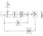
- FIG. 7is a simple flowchart for initiating testing of a sample vessel using the rack and carousel of the invention.
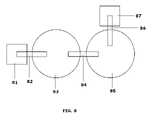
- FIG. 8is a schematic illustration of an automated immunoassay analyzer according to various embodiments of the invention.
- FIG. 1shows the subsystems for performing operations in an automated immunoassay analyzer; however, it should be understood that this invention can be practiced with chemical analyzers per se, and is not limited to use in automated immunoassay analyzers.
- Automated immunoassay analyzersare complex systems designed to process large numbers of patient samples obtained at a clinic or hospital with minimal involvement of a technician. It should be understood that this invention provides for sample handling in a highly automated and flexible manner, and may be amenable for use in a variety of existing automated chemical or immunoassay analyzers or could be incorporated in the future into newer automated chemical or immunoassay analyzers.
- the control system 101manages and coordinates the operations of all of the subsystems by sending commands and by receiving signals from the subsystems via the control bus 102 .
- samples of biological materiale.g., blood, urine, plasma, etc.
- Thiscan be accomplished manually, or by retrieving samples (and, most preferably in the preferred embodiment of this invention, linear racks containing samples) from a rack loader which has been loaded with samples obtained throughout, for example, a hospital or clinic.
- the samples within the sample subsystem 104can be diluted prior to making measurements or can be tested in their undiluted state depending on direction from the control subsystem 101 .
- a bead subsystem 105adds an appropriate substrate having a bound “analyte binding compound” to a test vessel in which, for example, an antibody-antigen binding interaction will be performed for testing for the amount of an antibody or antigen of interest in the sample.
- an antibody-antigen binding interactionwill be performed for testing for the amount of an antibody or antigen of interest in the sample.
- a large number of different analytescan be tested using beads or other substrates that are added to a test vessel.
- multiple tests for different analytes in the same samplecan be performed simply by adding the appropriate bead with bound analyte to each of several test vessels, and then adding sample from the sample tubes on the linear racks to each of the test vessels (i.e., immunoassay or chemical analyzers which include bead subsystems 105 provide for significant flexibility in processing samples for test).
- the reagent subsystem 103is used for adding reagents to test vessels under control of the control subsystem 101 .
- the incubator subsystem 106incubates test vessels, preferably with vessel agitation, for predetermined periods of time prior to testing, and the luminometer subsystem 107 performs measurements on samples which have been combined with reagents and beads, and which have been incubated and washed (it being understood that some analyzers may utilize phosphorescence, fluorescence, or colorimetric changes instead of chemiluminescence (the preferred indicator in the immunoassay embodiment of this invention)).
- Movement between stationsis accomplished using the transfer subsystem 108 .
- the control subsystem 101coordinates the operations being performed within subsystems 102 , 103 , 104 , 105 , 106 , and 107 , and the transfers being performed by transfer subsystem 108 , and preferably considers the tests being performed on all of the samples which have been loaded, thereby optimizing the order in which certain tests are performed.
- the control subsystem 101preferably accommodates rush or “STAT” tests such that certain tests on certain samples can be performed preferentially to other tests on other samples present in the automated chemical or biological analyzer.
- the subsystems 103 , 104 , 105 , 106 , and 107take advantage of identification technologies such as, for example, bar coding and RFIDs. That is, reagents loaded on a reagent subsystem 103 would be identified for the control subsystem 101 , so that the position of a particular reagent would be known and managed by the control subsystem 101 . Similarly, beads to be added to test vessels using the bead subsystem 105 , would be added using bar coded or RFID tagged bead dispensers (not shown), such that the control subsystem 101 would be made aware of the location of the beads to be dispensed.
- identification technologiessuch as, for example, bar coding and RFIDs.
- Notification for replenishment of the reagents or beadsmay be accomplished using sensors at the reagent subsystem 103 and the bead subsystem 105 which communicate information to the control subsystem 101 through the control bus 102 .
- the sample subsystem 104will utilize bar codes or RFID tags or other identification schemes to notify the control subsystem 101 of the location of a sample within the automated chemical or biological analyzer.
- the controllercan accommodate random and immediate access to any sample in any rack in any carousel.
- sample subsystem 104This invention is directed to the sample subsystem 104 .
- the sample subsystem 104can be employed in a wide variety of automated immunoassay analyzers, and should be applicable to any analyzer which requires access to multiple test samples for diagnostic purposes.
- FIG. 2shows a more detailed view of a preferred embodiment of a carousel system according to the present invention which is used in the sample subsystem 104 .
- FIG. 2shows a platform 1 on which is located two carousels 2 and 3 , a control storage element 4 , a pipetting station 5 (preferably, a similar pipetting station is positioned on the end of the platform adjacent carousel 3 and dilution station 6 so that two pipetters can be used to simultaneously pipette samples from two different sample tubes), a dilution station 6 , a plurality of transfer mechanisms 7 (the transfer mechanism between the loader and carousel being shown, and similar transfer mechanisms being present between carousels 2 and 3 , and between carousel 3 and control storage element 4 ), and sample identification system 8 .
- a pipetting station 5preferably, a similar pipetting station is positioned on the end of the platform adjacent carousel 3 and dilution station 6 so that two pipetters can be used to simultaneously pipette samples
- the number of carouselscan vary within the practice of the invention, and the practice of this invention contemplates its application to a single carousel, two carousels, or three or more carousels.
- the advantage of having several carousels,is that a large number of samples can be handled at any one time. Further, there is more flexibility in machine design and operation in using several smaller carousels as opposed to a single larger carousel.
- the location of the control storage element 4 , pipetting station 5 , and diluting station 6will vary depending on the number of carousels employed in the sample subsystem 104 .
- FIG. 2shows a single transfer mechanism 7 which obtains linear racks from a rack loader (not shown), it should be understood that an identical or similar transfer mechanism will be positioned so as to move linear racks between carousels 2 and 3 , and between carousel 3 and control storage element 4 .
- a sample in a linear rack that is loaded into a slot of carousel 2can remain in carousel 2 for a period of time determined by the tests to be performed in the linear rack, the tests to be performed in all of the other linear racks loaded into carousels 2 and 3 , and any priorities which have been set by a technician to perform some tests more quickly than others.
- carousels 2 and 3are preferably rotatable both in the clockwise and counterclockwise directions under computer control.
- Linear racks on carousels 2 and 3can travel around the full 360 degree rotation of either carousel any number of times before samples are retrieved by the pipetter 5 .
- a linear rackis rotated half a rotation of the carousel from the site of rack loading to the site of transfer from one carousel 2 to the other carousel 3 (best shown as the two aligned slots in carousels 2 and 3 at their closest point points to each other).
- the linear rackis then rotated to one or more positions which are accessible by one or more pipetters 5 for obtaining sample and transferring the sample to a test vessel. If required, dilutions can be performed at station 6 . It should be understood that other pipetting systems in addition to the pipetting station 5 shown in FIG.
- sample subsystem 2can be added and used in combination in the sample subsystem, and that pipetting can be used to retrieve sample from the linear rack for transferring to a test vessel (not shown) used in, for example, an immunoassay analyzer.
- samplescan remain on carousel 3 or be transferred back to carousel 2 and remain on carousel 2 until all tests on the samples in the rack are completed.
- the carousel systemmight allow for retrieval of a sample from either carousel or from more than one position on a single carousel.
- the control storage element 4preferably provides an onboard storage space in the automated chemical or biological sample analyzer for control samples which may be used to calibrate the analyzer prior to the performance of certain tests and/or periodically during operation of the analyzer.
- the control storage element 4preferably houses the control samples in a preferred storage environment which assures stability. For example, in most applications the environment will be designed to assure low evaporation rates for the control (e.g., low (e.g. refrigerator) temperatures, and possibly higher humidity).
- the control storage element 4preferably has a housing which protects the control samples from exposure to dust or other contaminants, as well as any damaging radiant energy (e.g., light or uv light) during extended operation of the analyzer.
- control samplesare added to the analyzer in the same manner as samples to be tested. That is, they are loaded onto a linear rack which will be either transferred automatically from a rack loader using transfer mechanism 7 into the first carousel 2 or will be manually placed on the transfer mechanism 7 for insertion into the first carousel. Thereafter, under computer control, the linear rack containing the control samples will be passed to the second carousel 3 and then will be passed into the control storage element 4 .
- the control storage element 4will house at least two linear storage racks filled with control samples. When needed, a transfer mechanism will transfer the linear rack with control samples back into the second carousel 3 , which will then transport the linear rack to the pipetting station 5 .
- the control samplecan then be either diluted at the diluting station 6 , or pipetted directly into a test vessel (not shown), which preferably passes along, under computer control, outside of platform 1 . Then, the linear rack with control sample will be moved back into the control storage element 4 using movements of carousel 3 and the transfe mechanism located between the carousel 3 and control storage element 4 .
- the configurationthus has the advantage that the operator is not required to periodically load control samples (they are stored on board).
- the configurationalso has the advantage of simplicity because the operator does not need any special mechanism to load the controls (i.e., they are loaded in the same manner as samples to be tested). However, it should be understood that in some applications, it may not be desirable to have control samples on board, and in these applications the control storage element 4 might simply be eliminated (in which case, the linear rack with the control samples would simply occupy a slot within one of the carousels).
- FIG. 2also shows an identification station 8 located adjacent to a transfer mechanism 7 .
- the identificationcan read bar codes, RFID tags, or other identifying markings on linear racks and sample tubes as they are loaded into carousel 2 from the rack loader using the transfer mechanism 7 .
- the identification information on the linear rack and sample tubeswill be relayed from the identification station 8 to the control system 101 , and by tracking the slot in carousel 2 in which the particular linear rack and sample tubes identified at identification station 8 is loaded, as well as the movements of the carousels 2 and 3 (if more than one carousel is employed), the control system 101 will be able to better control how and when a linear rack having particular samples thereon is presented to the pipetting station 5 for, for example, transferring sample to a test vessel to perform an immunoassay.
- the identifying information determined at identification station 8can thus be used to allow both random and immediate access to any sample stored in any rack in any slot in any carousel of the inventive system.
- the controllerpreferably considers all samples on board the carousels for determining an optimized order for tests, as well as the priorities of any rush tests to be performed.
- FIG. 3shows carousel 2 has a number of slots 11 separated by wedge regions 12 . Due to the shape of wedge regions 12 , the slots 11 are linear and extend along a radius of the carousel. The center section of each slot 11 has a guide slot 29 in which a component of the transfer mechanism, which will be discussed in more detail below, will be able to move freely when transporting a linear rack into the slot 11 . Furthermore, the guide slot 29 extends into the adjacent wedge region 12 , and the wedge region 12 has a groove 28 at its base so as to allow the component of the transfer mechanism to be withdrawn from the carousel 2 after a linear rack is installed. These grooves 28 and guide slots 29 are also used when the transfer mechanism retrieves a linear rack from the slot 11 of the carousel 2 .
- each slotpreferably includes an elastic spring member 13 which forces the linear rack against one of the side walls of the slot 11 .
- Having the linear rack forced against a side wall of a slotmay provide certain advantages in being able to more easily align the pipetter of pipetting station 5 .
- FIG. 3shows twenty slots in the carousel 2
- the number of slotscan vary depending on the design and needs of the analyzer.
- FIG. 2shows two carousels 2 and 3 of the same size with the same number of slots 11
- size of the carouselscould vary with respect to each other, as well as the number of slots 11 ; however, in any system requiring transfers between two adjacent carousels 2 and 3 , the analyzer will preferably be constructed such that the slots of adjacent carousels are aligned in order to effect a simple, linear transfer from one carousel to the other.
- the carousels 2 and 3preferably are each rotatable 360° in either the clockwise or counterclockwise direction, and movements are controlled by a computer in a coordinated fashion so as to allow alignment with a transfer mechanism to permit loading or retrieval of a linear rack in a slot, alignment of samples in the linear rack at a position accessible by a pipetter of pipetting station, transfer of a linear rack containing control samples into the control storage element 4 , etc.
- the carousels 2 and 3can be advanced any amount chosen under computer control, and are preferably not simple incrementally advanced devices.
- the carousels 2 and 3are preferably advancible in half increments so as to allow components of a linear transfer mechanism to either exit the carousel, or to allow insertion of the component into the carousel (via the grooved underside 28 of wedge region 12 ) to retrieve a linear rack therefrom.
- advancible in half incrementsso as to allow components of a linear transfer mechanism to either exit the carousel, or to allow insertion of the component into the carousel (via the grooved underside 28 of wedge region 12 ) to retrieve a linear rack therefrom.
- FIGS. 4 a and 4 bshow an isometric side view and a cross-sectional side view of the preferred linear racks 10 used in the practice of this invention.
- each linear rack 10will hold a plurality of sample tubes 14 and, while five tubes 14 are shown in the drawings, the number can vary within the practice of the invention.
- the tubes 14can be of varying size, and in an automated immunoassay analyzer embodiment contemplated by this invention, the tubes may range in diameter from 11 mm to 16 mm, and may range in height from 66 mm to 100 mm.
- the linear racks 10may have a spring bias in a back wall of each station of the rack, and the front portion of each station may be open.
- the stations for accommodating the tubes 14can be fully closed and may not require a spring bias mechanism.
- FIGS. 4 a and 4 balso make clear that the racks 10 do not need to be fully loaded during operation and use. That is, some stations may be empty.
- the bar code shown on the end of the rack 10 in FIG. 4 aidentifies the linear rack 10 .
- the linear rackhas a closed back side and an open front side. This will allow bar codes affixed to the tubes 14 to be read simultaneously with the same bar code reader that reads the bar code label on the rack 10 .
- the bar codecan be a label which is printed automatically by a computer, or may be generated by a technician when the tubes 14 are loaded into the linear rack 10 , with the label being attachable and detachable from the rack 10 and sample tubes 14 .
- the linear rack 10may be permanently marked (e.g., racks for control samples, etc.).
- RFID tagsmight be used on the linear racks 10 and test tubes 14 instead of bar code labels.
- FIGS. 4 a and 4 balso show that the linear racks 10 preferably include a transfer pin slot 15 in its base. As will be described in more detail below, this transfer pin slot 15 is used by one or more transfer mechanisms within the automated chemical or biological analyzer to move the linear racks 10 between stations (e.g., between carousels, between the rack loader and a carousel, between a carousel and a control storage component).
- stationse.g., between carousels, between the rack loader and a carousel, between a carousel and a control storage component.
- Movement of the linear rack 10may be accomplished, for example, by an upwardly projecting element engaging the pin slot 15 , then sliding the rack 10 in a given direction, then having the projecting element disengage from the linear rack 10 (such as by rotational movement of the carousel and withdrawal of the upwardly projecting element through the grooved region 28 in a wedge section 12 of the carousel).
- linear racks 10might include more than one feature to assist in movement between stations in the automated chemical and biological analyzer (e.g., more than one transfer pin slot 15 , etc.).
- FIGS. 4 a and 4 balso show that the linear rack 10 may also be formed with a detent 16 (to be discussed in more detail below) to assist in loading the linear rack 10 into a carousel 2 or 3 , and indentation region 18 which may assist in identifying the front end and back of the rack so that a technician does not insert the linear rack 10 in a rack loader incorrectly.
- a detent 16to assist in loading the linear rack 10 into a carousel 2 or 3
- indentation region 18which may assist in identifying the front end and back of the rack so that a technician does not insert the linear rack 10 in a rack loader incorrectly.
- the linear configurationallows for easy identification of a plurality of samples located at different spaces along the length of the linear rack 10 , easy loading of samples into the rack by technicians, and easy handling of the rack 10 by an automated rack loader.
- the linear configuration of the racks 10in conjunction with the carousels 2 or 3 of the present invention, permits the linear rack 10 to be transferred to a plurality of stations within an automated chemical or biological analyzer via simple linear movements of transfer devices (turning of the linear racks 10 is not required).
- FIG. 5highlights a preferred mechanism for retention of a linear rack 10 filled with a plurality of sample tubes 14 in a slot 11 of a carousel 2 (or 3 ).
- a button 19 positioned on flat spring 20 secured to the carousel 2 by connector 21is biased upwards so as to engage detent 16 in the bottom of the linear rack 10 .
- the linear rack 10is moved into the slot 11 of the carousel by the transfer mechanism, it is secured in the carousel by the button 19 engaging the detent 16 .
- the upwardly projecting member of the transfer mechanismis then permitted to exit the carousel by rotational movement of the carousel 2 such that the upwardly projecting member slides laterally out of engagement with the transfer pin slot 15 . Thereafter, the upwardly projecting member is permitted to slide out of the carousel 2 (or 3 ) through the groove 28 at the bottom of the adjacent wedge portion 12 .
- the upwardly projecting memberengages the transfer pin slot 15 and is used to pull the linear rack 10 out of the slot 11 in the carousel 2 (or 3 ).
- the button 19is pushed downward by the base of the linear rack 10 , thereby allowing the linear rack 10 to be transferred to its destination.
- the bottom of the linear rack 10preferably has detents 16 on its base at both ends.
- detents 16would be used, for example, when the linear rack 10 is transferred from one carousel to another (e.g., the first carousel would have a button member for engaging one end of the linear rack and the second carousel would have a button member for engaging the other end of the linear rack 10 ).
- other configurationscan be employed for temporarily securing the linear rack 10 within a carousel or at another station (e.g., control storage element 4 ), and that in some applications, a securing feature, such as the button 19 /detent 16 combination, may not be required.
- FIG. 6illustrates a preferred transfer mechanism used, for example, to transfer linear racks 10 from an automated rack loader to a carousel, to make transfers between carousels, and to make transfers to a control storage compartment.
- a drive belt 23 or chain positioned on spindles 22is used to move back and forth a transfer slide 25 having an upwardly projecting transfer pin 24 . Movement is achieved under computer control of the motor 27 .
- the transfer slide 25 and pin 24are used to transport the linear rack 10 into or out of, for example, a carousel 2 or 3 .
- the transfer mechanismonly move in a forward or reverse direction along a straight line.
- movements of the transfer mechanisms and carouselsmust be coordinated under computer control to allow installation of a rack in a carousel with subsequent movement of the transfer pin 24 out of the carousel through the groove in the bottom of the carousel, and vice versa.
- other transferring mechanismsmight be used within the practice of this invention, and that what is required is a mechanism that can be operated under computer control in a coordinated fashion with other moveable components to effect the transfer of a generally linear rack 10 between stations such as between a rack loader and a carousel, between carousels, and between a carousel and a control station.
- FIG. 7provides a simple flow diagram which describes a sequence of moving a linear rack 10 in a preferred embodiment of the test instrument (e.g., an automated chemical or biological analyzer) as depicted in FIGS. 1 and 2 of the application.
- sample and control rackscan be loaded manually into the rack loader (Step 70 ).
- the sample racksare moved through the rack loader (Step 71 ).
- the racksare then transferred into the “reflexive” carousel 2 by the transfer device 7 at step 72 .
- the sensor 8reads the identification data from the rack and sample tubes (e.g., bar codes or RFID tags on the rack and sample tubes) and exchanges this data with the control subsystem 101 at step 73 .
- a decisionis made at step 74 to determine if the rack that was loaded is a sample rack or a control rack. If the rack is a control rack, the rack is transferred to the control storage 4 at step 77 . This is accomplished by movement between one or more carousels, and ultimately installation in a control storage element 4 . If the rack is a sample rack, the sample rack is transferred to the sample carousel 3 via the reflexive carousel 2 at step 75 .
- the time when the transfer is madeis controlled by subsystem 101 , and it should be understood that racks can be moved back and forth between carousels to accommodate different orders in processing samples.
- the designated test processcan be performed at step 76 .
- the computer controllerwill be programmed to maintain one of the slots in one of the carousels empty (preferably a slot in reflexive carousel 2 ) so that rush or “STAT” tests can be easily and quickly added to the analyzer for processing at step 71 .
- All of the movements of the carousels and transfer devices, as well as operations of pipetting station 5are preferably operated under a coordinated, computer control which considers the tests to be performed which have been loaded into the analyzer, as well as any preferences for rush or “STAT” results.
- FIG. 8shows a schematic illustration of an automated immunoassay analyzer according to various embodiments of the invention.
- First transfer device 84allows for transfer between first carousel 83 and second carousel 85 .
- Second transfer deviceallows for between first carousel 83 and rack loader 81 .
- Third transfer deviceallows for transfer between second carousel 85 and control storage component 87 .
Landscapes
- Chemical & Material Sciences (AREA)
- Chemical Kinetics & Catalysis (AREA)
- Physics & Mathematics (AREA)
- Health & Medical Sciences (AREA)
- Life Sciences & Earth Sciences (AREA)
- Analytical Chemistry (AREA)
- Biochemistry (AREA)
- General Health & Medical Sciences (AREA)
- General Physics & Mathematics (AREA)
- Immunology (AREA)
- Pathology (AREA)
- Automatic Analysis And Handling Materials Therefor (AREA)
Abstract
Description
Claims (34)
Priority Applications (4)
| Application Number | Priority Date | Filing Date | Title |
|---|---|---|---|
| US11/087,809US7670553B2 (en) | 2005-03-24 | 2005-03-24 | Carousel system for automated chemical or biological analyzers employing linear racks |
| PCT/US2006/006714WO2006104616A2 (en) | 2005-03-24 | 2006-02-27 | Carousel system for automated chemical or biological analyzers employing linear racks |
| EP06736116.2AEP1901977A4 (en) | 2005-03-24 | 2006-02-27 | ROTATING PLATE SYSTEM FOR AUTOMATED CHEMICAL OR BIOLOGICAL ANALYZERS USING LINEAR BASKETS |
| JP2008502997AJP2008534924A (en) | 2005-03-24 | 2006-02-27 | Carousel system for automated chemical or biological analyzers using linear racks |
Applications Claiming Priority (1)
| Application Number | Priority Date | Filing Date | Title |
|---|---|---|---|
| US11/087,809US7670553B2 (en) | 2005-03-24 | 2005-03-24 | Carousel system for automated chemical or biological analyzers employing linear racks |
Publications (2)
| Publication Number | Publication Date |
|---|---|
| US20060245865A1 US20060245865A1 (en) | 2006-11-02 |
| US7670553B2true US7670553B2 (en) | 2010-03-02 |
Family
ID=37053854
Family Applications (1)
| Application Number | Title | Priority Date | Filing Date |
|---|---|---|---|
| US11/087,809Active2026-12-01US7670553B2 (en) | 2005-03-24 | 2005-03-24 | Carousel system for automated chemical or biological analyzers employing linear racks |
Country Status (4)
| Country | Link |
|---|---|
| US (1) | US7670553B2 (en) |
| EP (1) | EP1901977A4 (en) |
| JP (1) | JP2008534924A (en) |
| WO (1) | WO2006104616A2 (en) |
Cited By (28)
| Publication number | Priority date | Publication date | Assignee | Title |
|---|---|---|---|---|
| US20080199358A1 (en)* | 2007-02-19 | 2008-08-21 | Yamano Teruhiro | Automatic analyzer |
| US20090309726A1 (en)* | 2008-06-12 | 2009-12-17 | Abbott Laboratories | System for tracking the location of components, assemblies, and sub-assemblies in a medical instrument |
| US9207229B2 (en) | 2011-06-01 | 2015-12-08 | International Business Machines Corporation | Cartridge for storing biosample plates and use in automated data storage systems |
| US9250254B2 (en) | 2012-09-30 | 2016-02-02 | International Business Machines Corporation | Biosample cartridge with radial slots for storing biosample carriers and using in automated data storage systems |
| US9286914B2 (en) | 2011-06-01 | 2016-03-15 | International Business Machines Corporation | Cartridge for storing biosample capillary tubes and use in automated data storage systems |
| US9335338B2 (en) | 2013-03-15 | 2016-05-10 | Toshiba Medical Systems Corporation | Automated diagnostic analyzers having rear accessible track systems and related methods |
| US9381524B2 (en) | 2011-11-08 | 2016-07-05 | Becton, Dickinson And Company | System and method for automated sample preparation |
| US9400285B2 (en) | 2013-03-15 | 2016-07-26 | Abbot Laboratories | Automated diagnostic analyzers having vertically arranged carousels and related methods |
| US9513303B2 (en) | 2013-03-15 | 2016-12-06 | Abbott Laboratories | Light-blocking system for a diagnostic analyzer |
| US9632103B2 (en) | 2013-03-15 | 2017-04-25 | Abbott Laboraties | Linear track diagnostic analyzer |
| EP3196653A1 (en) | 2016-01-22 | 2017-07-26 | Roche Diagnostics GmbH | Sample handling device |
| US9835640B2 (en) | 2015-02-13 | 2017-12-05 | Abbott Laboratories | Automated storage modules for diagnostic analyzer liquids and related systems and methods |
| US20180156700A1 (en)* | 2015-05-25 | 2018-06-07 | Adarsh Natarajan | Automated sample stainer and a method thereof |
| US9993820B2 (en) | 2013-03-15 | 2018-06-12 | Abbott Laboratories | Automated reagent manager of a diagnostic analyzer system |
| US10001497B2 (en) | 2013-03-15 | 2018-06-19 | Abbott Laboratories | Diagnostic analyzers with pretreatment carousels and related methods |
| US10288633B2 (en) | 2015-06-26 | 2019-05-14 | Abbott Laboratories | Reaction vessel moving member for moving reaction vessels from a processing track to a rotating device in a diagnostic analyzer |
| US10379130B2 (en) | 2015-06-26 | 2019-08-13 | Abbott Laboratories | Reaction vessel exchanger device for a diagnostic analyzer |
| WO2019157220A3 (en)* | 2018-02-07 | 2020-04-23 | Abdullah Kazi | Method and system to improve all phases of ion-exchange resin regeneration |
| WO2020098957A1 (en) | 2018-11-16 | 2020-05-22 | Aixinno Limited | A process module for an automated biology system |
| WO2020098960A1 (en) | 2018-11-16 | 2020-05-22 | Aixinno Limited | A system for processing biology material, comprising a plurality of uniform design storage modules |
| WO2020098958A1 (en) | 2018-11-16 | 2020-05-22 | Aixinno Limited | Lab-ware and handling system to handle lab-ware in a cell culture process |
| WO2020098959A1 (en) | 2018-11-16 | 2020-05-22 | Aixinno Limited | Module for an automated biology laboratory system with an interface to transfer microplates or lab-ware |
| WO2020117802A1 (en)* | 2018-12-04 | 2020-06-11 | Bd Kiestra B.V. | Multiple carousel cartridge-based dispensing system and method |
| US10948506B2 (en) | 2017-12-01 | 2021-03-16 | Leica Biosystems Imaging, Inc. | Slide rack carousel |
| US11112419B2 (en) | 2016-01-22 | 2021-09-07 | Roche Diagnostics Operations, Inc. | Laboratory distribution system |
| US20210322993A1 (en)* | 2018-02-02 | 2021-10-21 | HighRes Biosolutions, Inc. | Robotic processing system |
| US20220195586A1 (en)* | 2020-12-23 | 2022-06-23 | Tsinghua University | Substrate holder for mass production of surface-enhanced raman scattering substrates |
| US12057195B2 (en) | 2017-04-27 | 2024-08-06 | Koninklijke Philips N.V. | System and method for real-time prioritization of sequencing |
Families Citing this family (30)
| Publication number | Priority date | Publication date | Assignee | Title |
|---|---|---|---|---|
| AU2004296404A1 (en)* | 2003-12-09 | 2005-06-23 | Spherics, Inc. | Bioadhesive polymers with catechol functionality |
| US20080311191A1 (en)* | 2004-08-27 | 2008-12-18 | Avinash Nangia | Multi-Layer Tablets and Bioadhesive Dosage Forms |
| WO2007103286A2 (en)* | 2006-03-02 | 2007-09-13 | Spherics, Inc. | Rate-controlled bioadhesive oral dosage formulations |
| US7688207B2 (en)* | 2006-07-28 | 2010-03-30 | Abbott Laboratories Inc. | System for tracking vessels in automated laboratory analyzers by radio frequency identification |
| JP2008209338A (en)* | 2007-02-28 | 2008-09-11 | Hitachi High-Technologies Corp | Automatic analyzer |
| US7681466B2 (en)* | 2007-05-01 | 2010-03-23 | Siemens Healthcare Diagnostics Inc. | Programmable random access sample handler for use within and automated laboratory system |
| US8459462B2 (en) | 2008-10-10 | 2013-06-11 | Quest Diagnostics Investments Incorporated | System and method for sorting specimen |
| JP5128441B2 (en)* | 2008-11-07 | 2013-01-23 | 株式会社イードクトル | Linking device for blood collection tube identification |
| WO2011043996A1 (en)* | 2009-10-06 | 2011-04-14 | Molecular Biometrics, Inc. | Verifying, via radio-frequency identification, completeness of a sample analysis in a chemical analytical procedure |
| JP5458963B2 (en)* | 2010-03-05 | 2014-04-02 | 株式会社島津製作所 | Carousel |
| FR2957676A1 (en)* | 2010-03-18 | 2011-09-23 | Sas Laboratoire | Machine for injecting reagent in sample of soil to be analyzed to indicate adaptability of soil for cultivation, has module controlling displacement of tube carrier, and needle injecting quantity of reagent adapted to quantity of sample |
| DE102010035155A1 (en)* | 2010-08-23 | 2012-02-23 | Amedo Smart Tracking Solutions Gmbh | Position determination by means of RFID tags |
| US9046504B2 (en)* | 2011-02-24 | 2015-06-02 | Kabushiki Kaisha Toshiba | Automatic analysis apparatus |
| US10401082B2 (en)* | 2013-02-20 | 2019-09-03 | Biotillion, Llc | Tracking of sample boxes using energy harvesting |
| JP6077992B2 (en)* | 2013-12-27 | 2017-02-08 | シスメックス株式会社 | Sample processing apparatus and rack |
| JP6898239B2 (en)* | 2015-01-23 | 2021-07-07 | エフ.ホフマン−ラ ロシュ アーゲーF. Hoffmann−La Roche Aktiengesellschaft | Loading device for loading the reagent container into the reagent rotor of the analytical instrument, and the analytical instrument |
| EP3153864B1 (en) | 2015-10-06 | 2019-11-20 | Roche Diagniostics GmbH | Apparatus and method for processing at least one sample |
| EP3153438B1 (en) | 2015-10-07 | 2019-11-20 | Roche Diagniostics GmbH | Laboratory distribution system for conveying test tube holders |
| CN105301227B (en)* | 2015-11-04 | 2017-03-29 | 徐恩良 | A kind of any project team's parallel reaction processing meanss of immune detection |
| EP3196655B1 (en) | 2016-01-22 | 2020-11-25 | Roche Diagniostics GmbH | Laboratory sample container carrier handling apparatus and laboratory system |
| EP3196648B1 (en) | 2016-01-22 | 2021-03-31 | Roche Diagniostics GmbH | Device for lifting a sample tube |
| EP3196654B1 (en)* | 2016-01-22 | 2023-06-21 | Roche Diagnostics GmbH | Method and device for transferring sample tubes between a laboratory automation system and a sample archiving system |
| US20170242980A1 (en)* | 2016-02-18 | 2017-08-24 | Q Squared Solutions Holdings LLC | Electronic writable memory devices for patient sample management |
| EP3239718B1 (en)* | 2016-04-27 | 2020-10-14 | Roche Diagniostics GmbH | Analyzer and method for loading a rack into a rack slot of an analyzer |
| FI128856B (en)* | 2016-06-29 | 2021-01-29 | Thermo Fisher Scientific Oy | Method for attaching a sample vessel rack in an apparatus, sample vessel rack and apparatus for a sample vessel rack |
| FR3061960B1 (en) | 2017-01-19 | 2019-05-31 | Horiba Abx Sas | SYSTEM OF BIOLOGICAL ANALYZES WITH TREATMENT OF SPECIFIC PORTALS |
| US12006126B2 (en) | 2019-09-03 | 2024-06-11 | Bio Tillion, Llc | Techniques for tracking physical parameters such as temperature of transported biological materials |
| CN110980178A (en)* | 2019-12-16 | 2020-04-10 | 华电重工股份有限公司 | Sample collecting and preparing system and method |
| AU2021359641A1 (en)* | 2020-10-15 | 2023-06-15 | Avicena Systems Limited | High-throughput screening apparatus |
| CN116577926B (en)* | 2023-07-12 | 2023-09-12 | 江苏微控生物科技有限公司 | Controllable batch automatic glass slide loading microscan |
Citations (59)
| Publication number | Priority date | Publication date | Assignee | Title |
|---|---|---|---|---|
| US3785773A (en)* | 1972-03-02 | 1974-01-15 | Beckman Instruments Inc | Chemical analysis tube module |
| US3832135A (en)* | 1972-04-05 | 1974-08-27 | Becton Dickinson Co | Automatic clinical analyzer |
| US4639242A (en) | 1985-02-04 | 1987-01-27 | Babson Arthur L | Vessel and procedure for automated assay |
| US4678752A (en)* | 1985-11-18 | 1987-07-07 | Becton, Dickinson And Company | Automatic random access analyzer |
| EP0290018A2 (en)* | 1987-05-08 | 1988-11-09 | Abbott Laboratories | Reagent pack and carousel |
| EP0325101A1 (en)* | 1988-01-22 | 1989-07-26 | Kabushiki Kaisha Toshiba | Automatic chemical analytical apparatus |
| JPH01189561A (en)* | 1988-01-25 | 1989-07-28 | Toshiba Corp | Transferring device of sample rack for automatic chemical analysis apparatus |
| JPH01212362A (en)* | 1988-02-19 | 1989-08-25 | Toshiba Corp | Automatic chemical analyzer |
| JPH01219564A (en)* | 1988-02-26 | 1989-09-01 | Toshiba Corp | Automatic chemical analyzing device |
| US4863693A (en)* | 1984-08-21 | 1989-09-05 | E. I. Du Pont De Nemours And Company | Analysis instrument having a blow molded reaction chamber |
| JPH01229975A (en)* | 1988-03-10 | 1989-09-13 | Toshiba Corp | automatic chemical analyzer |
| JPH01250759A (en)* | 1988-03-31 | 1989-10-05 | Toshiba Corp | Automatic apparatus for chemical analysis |
| US4956148A (en)* | 1987-04-22 | 1990-09-11 | Abbott Laboratories | Locking rack and disposable sample cartridge |
| US4970053A (en)* | 1986-07-11 | 1990-11-13 | Beckman Instruments, Inc. | Reagent cartridge |
| US5008082A (en) | 1988-08-25 | 1991-04-16 | Eastman Kodak Company | Analyzers using linear sample trays with random access |
| US5035861A (en)* | 1987-04-22 | 1991-07-30 | Abbott Laboratories | Locking rack and disposable sample cartridge |
| US5075082A (en)* | 1986-07-11 | 1991-12-24 | Beckman Instruments, Inc. | Reagent cartridge |
| US5084240A (en) | 1988-07-25 | 1992-01-28 | Cirrus Diagnostics Inc. | Centrifuge vessel for automated solid-phase immunoassay |
| US5098845A (en) | 1988-07-25 | 1992-03-24 | Cirrus Diagnostics, Inc. | Device and procedure for automated solid-phase immunoassay |
| US5128103A (en)* | 1990-12-14 | 1992-07-07 | E. I. Du Pont De Nemours And Company | Apparatus for automatically processing magnetic solid phase reagents |
| US5141871A (en)* | 1990-05-10 | 1992-08-25 | Pb Diagnostic Systems, Inc. | Fluid dispensing system with optical locator |
| US5147529A (en)* | 1988-08-10 | 1992-09-15 | E. I. Du Pont De Nemours And Company | Method for automatically processing magnetic solid phase reagents |
| US5167922A (en)* | 1990-04-27 | 1992-12-01 | Pb Diagnostic Systems Inc. | Assay cartridge |
| US5192506A (en)* | 1991-02-14 | 1993-03-09 | P B Diagnostic Systems, Inc. | Incubator port closure for automated assay system |
| US5207987A (en)* | 1990-05-21 | 1993-05-04 | Pb Diagnostic Systems Inc. | Temperature controlled chamber for diagnostic analyzer |
| US5219526A (en)* | 1990-04-27 | 1993-06-15 | Pb Diagnostic Systems Inc. | Assay cartridge |
| US5240678A (en)* | 1990-07-20 | 1993-08-31 | Eastman Kodak Company | Device for transporting containers filled with a liquid |
| US5258309A (en) | 1988-07-25 | 1993-11-02 | Cirrus Diagnostics, Inc. | Procedure for automated solid-phase immunoassay using a centrifuge tube |
| US5316726A (en) | 1991-07-26 | 1994-05-31 | Cirrus Diagnostics, Inc. | Automated immunoassay analyzer with pictorial display of assay information |
| US5318748A (en) | 1988-07-25 | 1994-06-07 | Cirrus Diagnostics, Inc. | Centrifuge vessel for automated solid-phase immunoassay having integral coaxial waste chamber |
| US5320808A (en)* | 1988-08-02 | 1994-06-14 | Abbott Laboratories | Reaction cartridge and carousel for biological sample analyzer |
| US5320809A (en)* | 1991-06-03 | 1994-06-14 | Abbott Laboratories | Retrofit kit for changing single immunoassay instrument to flexible multiple immunoassay instrument |
| US5324481A (en)* | 1991-06-03 | 1994-06-28 | Abbott Laboratories | Carousel for assay specimen carrier |
| US5358691A (en)* | 1992-03-27 | 1994-10-25 | Abbott Laboratories | Automated continuous and random access analytical system |
| US5380488A (en) | 1992-03-19 | 1995-01-10 | Kabushiki Kaisha Nittec | Container feeding system |
| US5620898A (en) | 1993-06-11 | 1997-04-15 | Ortho Diagnostic Systems Inc. | Automated blood analysis system |
| US5627522A (en) | 1992-03-27 | 1997-05-06 | Abbott Laboratories | Automated liquid level sensing system |
| US5632399A (en) | 1996-06-28 | 1997-05-27 | Dpc Cirrus Inc. | Self-sealing reagent container and reagent container system |
| US5646049A (en)* | 1992-03-27 | 1997-07-08 | Abbott Laboratories | Scheduling operation of an automated analytical system |
| US5721141A (en) | 1996-06-28 | 1998-02-24 | Dpc Cirrus Inc. | Tube washing system |
| US5723092A (en) | 1996-06-28 | 1998-03-03 | Dpc Cirrus Inc. | Sample dilution system and dilution well insert therefor |
| US5776784A (en)* | 1996-01-11 | 1998-07-07 | Dade International Inc. | Apparatus and method for reagent separation in a chemical analyzer |
| US5807523A (en) | 1996-07-03 | 1998-09-15 | Beckman Instruments, Inc. | Automatic chemistry analyzer |
| US5885530A (en)* | 1996-06-28 | 1999-03-23 | Dpc Cirrus, Inc. | Automated immunoassay analyzer |
| US5902549A (en) | 1996-03-11 | 1999-05-11 | Hitachi, Ltd. | Analyzer system having sample rack transfer line |
| US6074617A (en)* | 1998-07-10 | 2000-06-13 | Bayer Corporation | Stat shuttle adapter and transport device |
| US20030054542A1 (en) | 1998-05-01 | 2003-03-20 | Burns Ralph E. | Multiple ring assembly for providing specimen to reaction receptacles within an automated analyzer |
| US6723288B2 (en)* | 2002-04-29 | 2004-04-20 | Dade Behring Inc. | Method of providing assay processing in a multi-analyzer system |
| US20050013736A1 (en)* | 2003-07-18 | 2005-01-20 | Mckeever Robert Thomas | Operator interface module segmented by function in an automatic clinical analyzer |
| US20050106747A1 (en)* | 2003-07-09 | 2005-05-19 | Chaoui Sam M. | Automatic blood analysis and identification system |
| US20050159982A1 (en)* | 2003-07-17 | 2005-07-21 | Wayne Showalter | Laboratory instrumentation information management and control network |
| US6943030B2 (en)* | 2001-09-07 | 2005-09-13 | Dade Behring Inc. | Multi-compartment reagent container having means to inhibit re-use thereof |
| US7029922B2 (en)* | 2003-07-18 | 2006-04-18 | Dade Behring Inc. | Method for resupplying reagents in an automatic clinical analyzer |
| US7107936B2 (en)* | 2003-09-04 | 2006-09-19 | Mmi Genomics, Inc. | Device and method for animal tracking |
| US7112303B2 (en)* | 2003-01-31 | 2006-09-26 | Teruaki Itoh | Specimen centrifuge apparatus |
| US7169356B2 (en)* | 2003-07-18 | 2007-01-30 | Dade Behring Inc. | Random access reagent delivery system for use in an automatic clinical analyzer |
| US7175334B2 (en)* | 2004-03-31 | 2007-02-13 | Dpc Cirrus, Inc. | Vessel agitator assembly |
| US7390458B2 (en)* | 2000-10-13 | 2008-06-24 | Irm Llc | High throughput processing system and method of using |
| US7507377B2 (en)* | 2002-02-01 | 2009-03-24 | Stago Instruments | Device for automatic analysis of a liquid sample |
Family Cites Families (2)
| Publication number | Priority date | Publication date | Assignee | Title |
|---|---|---|---|---|
| US573092A (en)* | 1896-12-15 | Insulator | ||
| EP1099950A1 (en)* | 1999-11-12 | 2001-05-16 | F. Hoffmann-La Roche Ag | Analyzer having a rotatable sample rack carrier |
- 2005
- 2005-03-24USUS11/087,809patent/US7670553B2/enactiveActive
- 2006
- 2006-02-27JPJP2008502997Apatent/JP2008534924A/enactivePending
- 2006-02-27WOPCT/US2006/006714patent/WO2006104616A2/enactiveApplication Filing
- 2006-02-27EPEP06736116.2Apatent/EP1901977A4/enactivePending
Patent Citations (65)
| Publication number | Priority date | Publication date | Assignee | Title |
|---|---|---|---|---|
| US3785773A (en)* | 1972-03-02 | 1974-01-15 | Beckman Instruments Inc | Chemical analysis tube module |
| US3832135A (en)* | 1972-04-05 | 1974-08-27 | Becton Dickinson Co | Automatic clinical analyzer |
| US4863693A (en)* | 1984-08-21 | 1989-09-05 | E. I. Du Pont De Nemours And Company | Analysis instrument having a blow molded reaction chamber |
| US4639242A (en) | 1985-02-04 | 1987-01-27 | Babson Arthur L | Vessel and procedure for automated assay |
| US4678752A (en)* | 1985-11-18 | 1987-07-07 | Becton, Dickinson And Company | Automatic random access analyzer |
| US5075082A (en)* | 1986-07-11 | 1991-12-24 | Beckman Instruments, Inc. | Reagent cartridge |
| US4970053A (en)* | 1986-07-11 | 1990-11-13 | Beckman Instruments, Inc. | Reagent cartridge |
| US4956148A (en)* | 1987-04-22 | 1990-09-11 | Abbott Laboratories | Locking rack and disposable sample cartridge |
| US5035861A (en)* | 1987-04-22 | 1991-07-30 | Abbott Laboratories | Locking rack and disposable sample cartridge |
| EP0290018A2 (en)* | 1987-05-08 | 1988-11-09 | Abbott Laboratories | Reagent pack and carousel |
| US4849177A (en)* | 1987-05-08 | 1989-07-18 | Abbott Laboratories | Reagent pack and carousel |
| EP0325101A1 (en)* | 1988-01-22 | 1989-07-26 | Kabushiki Kaisha Toshiba | Automatic chemical analytical apparatus |
| JPH01189561A (en)* | 1988-01-25 | 1989-07-28 | Toshiba Corp | Transferring device of sample rack for automatic chemical analysis apparatus |
| JPH01212362A (en)* | 1988-02-19 | 1989-08-25 | Toshiba Corp | Automatic chemical analyzer |
| JPH01219564A (en)* | 1988-02-26 | 1989-09-01 | Toshiba Corp | Automatic chemical analyzing device |
| JPH01229975A (en)* | 1988-03-10 | 1989-09-13 | Toshiba Corp | automatic chemical analyzer |
| JPH01250759A (en)* | 1988-03-31 | 1989-10-05 | Toshiba Corp | Automatic apparatus for chemical analysis |
| US5098845A (en) | 1988-07-25 | 1992-03-24 | Cirrus Diagnostics, Inc. | Device and procedure for automated solid-phase immunoassay |
| US5084240A (en) | 1988-07-25 | 1992-01-28 | Cirrus Diagnostics Inc. | Centrifuge vessel for automated solid-phase immunoassay |
| US5318748A (en) | 1988-07-25 | 1994-06-07 | Cirrus Diagnostics, Inc. | Centrifuge vessel for automated solid-phase immunoassay having integral coaxial waste chamber |
| US5258309A (en) | 1988-07-25 | 1993-11-02 | Cirrus Diagnostics, Inc. | Procedure for automated solid-phase immunoassay using a centrifuge tube |
| US5320808A (en)* | 1988-08-02 | 1994-06-14 | Abbott Laboratories | Reaction cartridge and carousel for biological sample analyzer |
| US5147529A (en)* | 1988-08-10 | 1992-09-15 | E. I. Du Pont De Nemours And Company | Method for automatically processing magnetic solid phase reagents |
| US5008082A (en) | 1988-08-25 | 1991-04-16 | Eastman Kodak Company | Analyzers using linear sample trays with random access |
| US5219526A (en)* | 1990-04-27 | 1993-06-15 | Pb Diagnostic Systems Inc. | Assay cartridge |
| US5167922A (en)* | 1990-04-27 | 1992-12-01 | Pb Diagnostic Systems Inc. | Assay cartridge |
| US5141871A (en)* | 1990-05-10 | 1992-08-25 | Pb Diagnostic Systems, Inc. | Fluid dispensing system with optical locator |
| US5207987A (en)* | 1990-05-21 | 1993-05-04 | Pb Diagnostic Systems Inc. | Temperature controlled chamber for diagnostic analyzer |
| US5240678A (en)* | 1990-07-20 | 1993-08-31 | Eastman Kodak Company | Device for transporting containers filled with a liquid |
| US5128103A (en)* | 1990-12-14 | 1992-07-07 | E. I. Du Pont De Nemours And Company | Apparatus for automatically processing magnetic solid phase reagents |
| US5192506A (en)* | 1991-02-14 | 1993-03-09 | P B Diagnostic Systems, Inc. | Incubator port closure for automated assay system |
| US5320809A (en)* | 1991-06-03 | 1994-06-14 | Abbott Laboratories | Retrofit kit for changing single immunoassay instrument to flexible multiple immunoassay instrument |
| US5324481A (en)* | 1991-06-03 | 1994-06-28 | Abbott Laboratories | Carousel for assay specimen carrier |
| US5316726A (en) | 1991-07-26 | 1994-05-31 | Cirrus Diagnostics, Inc. | Automated immunoassay analyzer with pictorial display of assay information |
| US5380488A (en) | 1992-03-19 | 1995-01-10 | Kabushiki Kaisha Nittec | Container feeding system |
| US5358691A (en)* | 1992-03-27 | 1994-10-25 | Abbott Laboratories | Automated continuous and random access analytical system |
| US5627522A (en) | 1992-03-27 | 1997-05-06 | Abbott Laboratories | Automated liquid level sensing system |
| US5646049A (en)* | 1992-03-27 | 1997-07-08 | Abbott Laboratories | Scheduling operation of an automated analytical system |
| US5620898A (en) | 1993-06-11 | 1997-04-15 | Ortho Diagnostic Systems Inc. | Automated blood analysis system |
| US5776784A (en)* | 1996-01-11 | 1998-07-07 | Dade International Inc. | Apparatus and method for reagent separation in a chemical analyzer |
| US5902549A (en) | 1996-03-11 | 1999-05-11 | Hitachi, Ltd. | Analyzer system having sample rack transfer line |
| US5632399A (en) | 1996-06-28 | 1997-05-27 | Dpc Cirrus Inc. | Self-sealing reagent container and reagent container system |
| US5723092A (en) | 1996-06-28 | 1998-03-03 | Dpc Cirrus Inc. | Sample dilution system and dilution well insert therefor |
| US5721141A (en) | 1996-06-28 | 1998-02-24 | Dpc Cirrus Inc. | Tube washing system |
| US5885530A (en)* | 1996-06-28 | 1999-03-23 | Dpc Cirrus, Inc. | Automated immunoassay analyzer |
| US5885529A (en) | 1996-06-28 | 1999-03-23 | Dpc Cirrus, Inc. | Automated immunoassay analyzer |
| US6027691A (en)* | 1996-07-03 | 2000-02-22 | Beckman Coulter, Inc. | Automatic chemistry analyzer |
| US5807523A (en) | 1996-07-03 | 1998-09-15 | Beckman Instruments, Inc. | Automatic chemistry analyzer |
| US5902548A (en)* | 1996-07-03 | 1999-05-11 | Beckman Instruments, Inc. | Automatic chemistry analyzer |
| US20030054542A1 (en) | 1998-05-01 | 2003-03-20 | Burns Ralph E. | Multiple ring assembly for providing specimen to reaction receptacles within an automated analyzer |
| US6074617A (en)* | 1998-07-10 | 2000-06-13 | Bayer Corporation | Stat shuttle adapter and transport device |
| US6358472B1 (en)* | 1998-07-10 | 2002-03-19 | Bayer Corporation | Stat shuttle transport device |
| US7390458B2 (en)* | 2000-10-13 | 2008-06-24 | Irm Llc | High throughput processing system and method of using |
| US6943030B2 (en)* | 2001-09-07 | 2005-09-13 | Dade Behring Inc. | Multi-compartment reagent container having means to inhibit re-use thereof |
| US7507377B2 (en)* | 2002-02-01 | 2009-03-24 | Stago Instruments | Device for automatic analysis of a liquid sample |
| US6723288B2 (en)* | 2002-04-29 | 2004-04-20 | Dade Behring Inc. | Method of providing assay processing in a multi-analyzer system |
| US7112303B2 (en)* | 2003-01-31 | 2006-09-26 | Teruaki Itoh | Specimen centrifuge apparatus |
| US20050106747A1 (en)* | 2003-07-09 | 2005-05-19 | Chaoui Sam M. | Automatic blood analysis and identification system |
| US20050159982A1 (en)* | 2003-07-17 | 2005-07-21 | Wayne Showalter | Laboratory instrumentation information management and control network |
| US7029922B2 (en)* | 2003-07-18 | 2006-04-18 | Dade Behring Inc. | Method for resupplying reagents in an automatic clinical analyzer |
| US7169356B2 (en)* | 2003-07-18 | 2007-01-30 | Dade Behring Inc. | Random access reagent delivery system for use in an automatic clinical analyzer |
| US7185288B2 (en)* | 2003-07-18 | 2007-02-27 | Dade Behring Inc. | Operator interface module segmented by function in an automatic clinical analyzer |
| US20050013736A1 (en)* | 2003-07-18 | 2005-01-20 | Mckeever Robert Thomas | Operator interface module segmented by function in an automatic clinical analyzer |
| US7107936B2 (en)* | 2003-09-04 | 2006-09-19 | Mmi Genomics, Inc. | Device and method for animal tracking |
| US7175334B2 (en)* | 2004-03-31 | 2007-02-13 | Dpc Cirrus, Inc. | Vessel agitator assembly |
Cited By (53)
| Publication number | Priority date | Publication date | Assignee | Title |
|---|---|---|---|---|
| US20080199358A1 (en)* | 2007-02-19 | 2008-08-21 | Yamano Teruhiro | Automatic analyzer |
| US8048374B2 (en)* | 2007-02-19 | 2011-11-01 | Hitachi High-Technologies Corporation | Automatic analyzer |
| US20090309726A1 (en)* | 2008-06-12 | 2009-12-17 | Abbott Laboratories | System for tracking the location of components, assemblies, and sub-assemblies in a medical instrument |
| US7932826B2 (en)* | 2008-06-12 | 2011-04-26 | Abbott Laboratories Inc. | System for tracking the location of components, assemblies, and subassemblies in an automated diagnostic analyzer |
| US10052634B2 (en) | 2011-06-01 | 2018-08-21 | International Business Machines Corporation | Cartridge for storing biosample capillary tubes and use in automated data storage systems |
| US9207229B2 (en) | 2011-06-01 | 2015-12-08 | International Business Machines Corporation | Cartridge for storing biosample plates and use in automated data storage systems |
| US9286914B2 (en) | 2011-06-01 | 2016-03-15 | International Business Machines Corporation | Cartridge for storing biosample capillary tubes and use in automated data storage systems |
| US9381524B2 (en) | 2011-11-08 | 2016-07-05 | Becton, Dickinson And Company | System and method for automated sample preparation |
| US9931644B2 (en) | 2011-11-08 | 2018-04-03 | Becton, Dickinson And Company | System and method for automated sample preparation |
| US9250254B2 (en) | 2012-09-30 | 2016-02-02 | International Business Machines Corporation | Biosample cartridge with radial slots for storing biosample carriers and using in automated data storage systems |
| US12007403B2 (en) | 2013-03-15 | 2024-06-11 | Abbott Laboratories | Automated diagnostic analyzers having rear accessible track systems and related methods |
| US10001497B2 (en) | 2013-03-15 | 2018-06-19 | Abbott Laboratories | Diagnostic analyzers with pretreatment carousels and related methods |
| US12228583B2 (en) | 2013-03-15 | 2025-02-18 | Abbott Laboratories | Automated diagnostic analyzers having vertically arranged carousels and related methods |
| US9513303B2 (en) | 2013-03-15 | 2016-12-06 | Abbott Laboratories | Light-blocking system for a diagnostic analyzer |
| US9400285B2 (en) | 2013-03-15 | 2016-07-26 | Abbot Laboratories | Automated diagnostic analyzers having vertically arranged carousels and related methods |
| US9335338B2 (en) | 2013-03-15 | 2016-05-10 | Toshiba Medical Systems Corporation | Automated diagnostic analyzers having rear accessible track systems and related methods |
| US9993820B2 (en) | 2013-03-15 | 2018-06-12 | Abbott Laboratories | Automated reagent manager of a diagnostic analyzer system |
| US9632103B2 (en) | 2013-03-15 | 2017-04-25 | Abbott Laboraties | Linear track diagnostic analyzer |
| US10775398B2 (en) | 2013-03-15 | 2020-09-15 | Abbott Laboratories | Automated diagnostic analyzers having vertically arranged carousels and related methods |
| US10197585B2 (en) | 2013-03-15 | 2019-02-05 | Abbott Laboratories | Automated diagnostic analyzers having vertically arranged carousels and related methods |
| US10267818B2 (en) | 2013-03-15 | 2019-04-23 | Abbott Laboratories | Automated diagnostic analyzers having rear accessible track systems and related methods |
| US11536739B2 (en) | 2013-03-15 | 2022-12-27 | Abbott Laboratories | Automated diagnostic analyzers having vertically arranged carousels and related methods |
| US10330691B2 (en) | 2013-03-15 | 2019-06-25 | Abbott Laboratories | Light-blocking system for a diagnostic analyzer |
| US11435372B2 (en) | 2013-03-15 | 2022-09-06 | Abbott Laboratories | Diagnostic analyzers with pretreatment carousels and related methods |
| US11125766B2 (en) | 2013-03-15 | 2021-09-21 | Abbott Laboratories | Automated diagnostic analyzers having rear accessible track systems and related methods |
| US9835640B2 (en) | 2015-02-13 | 2017-12-05 | Abbott Laboratories | Automated storage modules for diagnostic analyzer liquids and related systems and methods |
| US10775399B2 (en) | 2015-02-13 | 2020-09-15 | Abbott Laboratories | Automated storage modules for diagnostic analyzer liquids and related systems and methods |
| US20180156700A1 (en)* | 2015-05-25 | 2018-06-07 | Adarsh Natarajan | Automated sample stainer and a method thereof |
| US10379130B2 (en) | 2015-06-26 | 2019-08-13 | Abbott Laboratories | Reaction vessel exchanger device for a diagnostic analyzer |
| US12210029B2 (en) | 2015-06-26 | 2025-01-28 | Abbott Laboratories | Reaction vessel moving member for moving reaction vessels from a processing track to a rotating device in a diagnostic analyzer |
| US11733257B2 (en) | 2015-06-26 | 2023-08-22 | Abbott Laboratories | Reaction vessel moving member for moving reaction vessels from a processing track to a rotating device in a diagnostic analzyer |
| US10288633B2 (en) | 2015-06-26 | 2019-05-14 | Abbott Laboratories | Reaction vessel moving member for moving reaction vessels from a processing track to a rotating device in a diagnostic analyzer |
| EP3196653A1 (en) | 2016-01-22 | 2017-07-26 | Roche Diagnostics GmbH | Sample handling device |
| US10983138B2 (en) | 2016-01-22 | 2021-04-20 | Roche Diagnostics Operations, Inc. | Sample handling device |
| US11112419B2 (en) | 2016-01-22 | 2021-09-07 | Roche Diagnostics Operations, Inc. | Laboratory distribution system |
| US12057195B2 (en) | 2017-04-27 | 2024-08-06 | Koninklijke Philips N.V. | System and method for real-time prioritization of sequencing |
| US10948506B2 (en) | 2017-12-01 | 2021-03-16 | Leica Biosystems Imaging, Inc. | Slide rack carousel |
| US20230391553A1 (en)* | 2018-02-02 | 2023-12-07 | HighRes Biosolutions, Inc. | Robotic processing system |
| US12258212B2 (en)* | 2018-02-02 | 2025-03-25 | HighRes Biosolutions, Inc. | Robotic processing system |
| US20210322993A1 (en)* | 2018-02-02 | 2021-10-21 | HighRes Biosolutions, Inc. | Robotic processing system |
| US11679933B2 (en)* | 2018-02-02 | 2023-06-20 | HighRes Biosolutions, Inc. | Robotic processing system |
| WO2019157220A3 (en)* | 2018-02-07 | 2020-04-23 | Abdullah Kazi | Method and system to improve all phases of ion-exchange resin regeneration |
| WO2020098958A1 (en) | 2018-11-16 | 2020-05-22 | Aixinno Limited | Lab-ware and handling system to handle lab-ware in a cell culture process |
| WO2020098960A1 (en) | 2018-11-16 | 2020-05-22 | Aixinno Limited | A system for processing biology material, comprising a plurality of uniform design storage modules |
| WO2020098957A1 (en) | 2018-11-16 | 2020-05-22 | Aixinno Limited | A process module for an automated biology system |
| US12105106B2 (en) | 2018-11-16 | 2024-10-01 | Aixinno Limited | Process module for an automated biology system |
| WO2020098959A1 (en) | 2018-11-16 | 2020-05-22 | Aixinno Limited | Module for an automated biology laboratory system with an interface to transfer microplates or lab-ware |
| US12372546B2 (en) | 2018-11-16 | 2025-07-29 | Aixinno Ltd. | Module for an automated biology laboratory system with an interface to transfer microplates or lab-ware |
| US12019086B2 (en) | 2018-12-04 | 2024-06-25 | Bd Kiestra B.V. | Multiple carousel cartridge-based dispensing system and method |
| WO2020117802A1 (en)* | 2018-12-04 | 2020-06-11 | Bd Kiestra B.V. | Multiple carousel cartridge-based dispensing system and method |
| US11385249B2 (en) | 2018-12-04 | 2022-07-12 | Bd Kiestra B.V. | Multiple carousel cartridge-based dispensing system and method |
| AU2019392468B2 (en)* | 2018-12-04 | 2025-06-05 | Bd Kiestra B.V. | Multiple carousel cartridge-based dispensing system and method |
| US20220195586A1 (en)* | 2020-12-23 | 2022-06-23 | Tsinghua University | Substrate holder for mass production of surface-enhanced raman scattering substrates |
Also Published As
| Publication number | Publication date |
|---|---|
| EP1901977A2 (en) | 2008-03-26 |
| EP1901977A4 (en) | 2015-12-23 |
| WO2006104616A2 (en) | 2006-10-05 |
| US20060245865A1 (en) | 2006-11-02 |
| WO2006104616A3 (en) | 2007-12-13 |
| JP2008534924A (en) | 2008-08-28 |
Similar Documents
| Publication | Publication Date | Title |
|---|---|---|
| US7670553B2 (en) | Carousel system for automated chemical or biological analyzers employing linear racks | |
| EP2175279B1 (en) | Assay testing diagnostic analyzer | |
| US9656266B2 (en) | Assay testing diagnostic analyzer | |
| EP1465728B1 (en) | Stackable aliquot vessel array | |
| EP2972219B1 (en) | Automated reagent manager of a diagnostic analyzer system | |
| US20090028754A1 (en) | Insert for Restraining Tube Rotation in a Sample Tube Rack | |
| US9823261B2 (en) | Multi-well wedge-shaped reagent container with auto-open capability | |
| JP2015118091A (en) | Storage and supply for vessel holder | |
| CN102292645A (en) | Automated analyzer and automatic analysis method | |
| EP3422016B1 (en) | Specimen-container loading/storing unit | |
| EP3173793B1 (en) | Laboratory instrument and a method of operating a laboratory instrument | |
| JP7321179B2 (en) | locking structure | |
| US5773296A (en) | Bead dispenser and bead dispenser system for immunoassay analysis | |
| EP1648612B1 (en) | Magazine for inventorying reaction cuvettes in an automatic analyzer |
Legal Events
| Date | Code | Title | Description |
|---|---|---|---|
| AS | Assignment | Owner name:DPC CIRRUS, INC., NEW JERSEY Free format text:ASSIGNMENT OF ASSIGNORS INTEREST;ASSIGNOR:BABSON, ARTHUR L.;REEL/FRAME:016412/0952 Effective date:20040324 Owner name:DPC CIRRUS, INC.,NEW JERSEY Free format text:ASSIGNMENT OF ASSIGNORS INTEREST;ASSIGNOR:BABSON, ARTHUR L.;REEL/FRAME:016412/0952 Effective date:20040324 | |
| AS | Assignment | Owner name:SIEMENS MEDICAL SOLUTIONS DIAGNOSTICS,NEW JERSEY Free format text:CHANGE OF NAME;ASSIGNOR:DPC CIRRUS INC.;REEL/FRAME:019002/0127 Effective date:20061227 Owner name:SIEMENS MEDICAL SOLUTIONS DIAGNOSTICS, NEW JERSEY Free format text:CHANGE OF NAME;ASSIGNOR:DPC CIRRUS INC.;REEL/FRAME:019002/0127 Effective date:20061227 | |
| AS | Assignment | Owner name:SIEMENS HEALTHCARE DIAGNOSTICS INC., NEW YORK Free format text:CHANGE OF NAME;ASSIGNOR:SIEMENS MEDICAL SOLUTIONS DIAGNOSTICS;REEL/FRAME:020333/0976 Effective date:20071231 Owner name:SIEMENS HEALTHCARE DIAGNOSTICS INC.,NEW YORK Free format text:CHANGE OF NAME;ASSIGNOR:SIEMENS MEDICAL SOLUTIONS DIAGNOSTICS;REEL/FRAME:020333/0976 Effective date:20071231 | |
| STCF | Information on status: patent grant | Free format text:PATENTED CASE | |
| FPAY | Fee payment | Year of fee payment:4 | |
| FPAY | Fee payment | Year of fee payment:8 | |
| MAFP | Maintenance fee payment | Free format text:PAYMENT OF MAINTENANCE FEE, 12TH YEAR, LARGE ENTITY (ORIGINAL EVENT CODE: M1553); ENTITY STATUS OF PATENT OWNER: LARGE ENTITY Year of fee payment:12 |