US7670343B2 - Method and apparatus for reaming an acetabulum - Google Patents
Method and apparatus for reaming an acetabulumDownload PDFInfo
- Publication number
- US7670343B2 US7670343B2US11/453,312US45331206AUS7670343B2US 7670343 B2US7670343 B2US 7670343B2US 45331206 AUS45331206 AUS 45331206AUS 7670343 B2US7670343 B2US 7670343B2
- Authority
- US
- United States
- Prior art keywords
- longitudinal shaft
- tool
- guide
- axis
- stop member
- Prior art date
- Legal status (The legal status is an assumption and is not a legal conclusion. Google has not performed a legal analysis and makes no representation as to the accuracy of the status listed.)
- Expired - Fee Related, expires
Links
- 238000000034methodMethods0.000titleabstractdescription10
- 210000000588acetabulumAnatomy0.000titledescription16
- 210000000988bone and boneAnatomy0.000claimsabstractdescription17
- 230000000994depressogenic effectEffects0.000claimsdescription4
- 230000007547defectEffects0.000description14
- 238000003780insertionMethods0.000description8
- 230000037431insertionEffects0.000description8
- 230000013011matingEffects0.000description6
- 238000001356surgical procedureMethods0.000description3
- 230000000295complement effectEffects0.000description2
- 230000008878couplingEffects0.000description2
- 238000010168coupling processMethods0.000description2
- 238000005859coupling reactionMethods0.000description2
- 230000005786degenerative changesEffects0.000description2
- 210000001624hipAnatomy0.000description2
- 210000004394hip jointAnatomy0.000description2
- 230000003116impacting effectEffects0.000description2
- 239000007943implantSubstances0.000description2
- 239000000463materialSubstances0.000description2
- 230000000399orthopedic effectEffects0.000description2
- 238000013519translationMethods0.000description2
- 239000004698PolyethyleneSubstances0.000description1
- 210000001188articular cartilageAnatomy0.000description1
- 239000002639bone cementSubstances0.000description1
- 210000000845cartilageAnatomy0.000description1
- 238000013461designMethods0.000description1
- 238000009434installationMethods0.000description1
- 230000002427irreversible effectEffects0.000description1
- 239000002184metalSubstances0.000description1
- 238000012986modificationMethods0.000description1
- 230000004048modificationEffects0.000description1
- -1polyethylenePolymers0.000description1
- 229920000573polyethylenePolymers0.000description1
- 210000003813thumbAnatomy0.000description1
- 230000007704transitionEffects0.000description1
Images


Classifications
- A—HUMAN NECESSITIES
- A61—MEDICAL OR VETERINARY SCIENCE; HYGIENE
- A61B—DIAGNOSIS; SURGERY; IDENTIFICATION
- A61B17/00—Surgical instruments, devices or methods
- A61B17/16—Instruments for performing osteoclasis; Drills or chisels for bones; Trepans
- A61B17/1662—Instruments for performing osteoclasis; Drills or chisels for bones; Trepans for particular parts of the body
- A61B17/1664—Instruments for performing osteoclasis; Drills or chisels for bones; Trepans for particular parts of the body for the hip
- A61B17/1666—Instruments for performing osteoclasis; Drills or chisels for bones; Trepans for particular parts of the body for the hip for the acetabulum
- A—HUMAN NECESSITIES
- A61—MEDICAL OR VETERINARY SCIENCE; HYGIENE
- A61B—DIAGNOSIS; SURGERY; IDENTIFICATION
- A61B17/00—Surgical instruments, devices or methods
- A61B17/16—Instruments for performing osteoclasis; Drills or chisels for bones; Trepans
- A61B17/17—Guides or aligning means for drills, mills, pins or wires
- A61B17/1739—Guides or aligning means for drills, mills, pins or wires specially adapted for particular parts of the body
- A61B17/1742—Guides or aligning means for drills, mills, pins or wires specially adapted for particular parts of the body for the hip
- A61B17/1746—Guides or aligning means for drills, mills, pins or wires specially adapted for particular parts of the body for the hip for the acetabulum
- A—HUMAN NECESSITIES
- A61—MEDICAL OR VETERINARY SCIENCE; HYGIENE
- A61B—DIAGNOSIS; SURGERY; IDENTIFICATION
- A61B17/00—Surgical instruments, devices or methods
- A61B17/56—Surgical instruments or methods for treatment of bones or joints; Devices specially adapted therefor
- A61B17/58—Surgical instruments or methods for treatment of bones or joints; Devices specially adapted therefor for osteosynthesis, e.g. bone plates, screws or setting implements
- A61B17/68—Internal fixation devices, including fasteners and spinal fixators, even if a part thereof projects from the skin
- A61B17/84—Fasteners therefor or fasteners being internal fixation devices
- A61B17/86—Pins or screws or threaded wires; nuts therefor
- A—HUMAN NECESSITIES
- A61—MEDICAL OR VETERINARY SCIENCE; HYGIENE
- A61B—DIAGNOSIS; SURGERY; IDENTIFICATION
- A61B50/00—Containers, covers, furniture or holders specially adapted for surgical or diagnostic appliances or instruments, e.g. sterile covers
- A61B50/30—Containers specially adapted for packaging, protecting, dispensing, collecting or disposing of surgical or diagnostic appliances or instruments
- A61B50/33—Trays
- A—HUMAN NECESSITIES
- A61—MEDICAL OR VETERINARY SCIENCE; HYGIENE
- A61F—FILTERS IMPLANTABLE INTO BLOOD VESSELS; PROSTHESES; DEVICES PROVIDING PATENCY TO, OR PREVENTING COLLAPSING OF, TUBULAR STRUCTURES OF THE BODY, e.g. STENTS; ORTHOPAEDIC, NURSING OR CONTRACEPTIVE DEVICES; FOMENTATION; TREATMENT OR PROTECTION OF EYES OR EARS; BANDAGES, DRESSINGS OR ABSORBENT PADS; FIRST-AID KITS
- A61F2/00—Filters implantable into blood vessels; Prostheses, i.e. artificial substitutes or replacements for parts of the body; Appliances for connecting them with the body; Devices providing patency to, or preventing collapsing of, tubular structures of the body, e.g. stents
- A61F2/02—Prostheses implantable into the body
- A61F2/30—Joints
- A61F2/46—Special tools for implanting artificial joints
- A61F2/4603—Special tools for implanting artificial joints for insertion or extraction of endoprosthetic joints or of accessories thereof
- A61F2/4609—Special tools for implanting artificial joints for insertion or extraction of endoprosthetic joints or of accessories thereof of acetabular cups
- A—HUMAN NECESSITIES
- A61—MEDICAL OR VETERINARY SCIENCE; HYGIENE
- A61F—FILTERS IMPLANTABLE INTO BLOOD VESSELS; PROSTHESES; DEVICES PROVIDING PATENCY TO, OR PREVENTING COLLAPSING OF, TUBULAR STRUCTURES OF THE BODY, e.g. STENTS; ORTHOPAEDIC, NURSING OR CONTRACEPTIVE DEVICES; FOMENTATION; TREATMENT OR PROTECTION OF EYES OR EARS; BANDAGES, DRESSINGS OR ABSORBENT PADS; FIRST-AID KITS
- A61F2/00—Filters implantable into blood vessels; Prostheses, i.e. artificial substitutes or replacements for parts of the body; Appliances for connecting them with the body; Devices providing patency to, or preventing collapsing of, tubular structures of the body, e.g. stents
- A61F2/02—Prostheses implantable into the body
- A61F2/30—Joints
- A61F2/30721—Accessories
- A61F2/30734—Modular inserts, sleeves or augments, e.g. placed on proximal part of stem for fixation purposes or wedges for bridging a bone defect
- A61F2002/30736—Augments or augmentation pieces, e.g. wedges or blocks for bridging a bone defect
- A—HUMAN NECESSITIES
- A61—MEDICAL OR VETERINARY SCIENCE; HYGIENE
- A61F—FILTERS IMPLANTABLE INTO BLOOD VESSELS; PROSTHESES; DEVICES PROVIDING PATENCY TO, OR PREVENTING COLLAPSING OF, TUBULAR STRUCTURES OF THE BODY, e.g. STENTS; ORTHOPAEDIC, NURSING OR CONTRACEPTIVE DEVICES; FOMENTATION; TREATMENT OR PROTECTION OF EYES OR EARS; BANDAGES, DRESSINGS OR ABSORBENT PADS; FIRST-AID KITS
- A61F2/00—Filters implantable into blood vessels; Prostheses, i.e. artificial substitutes or replacements for parts of the body; Appliances for connecting them with the body; Devices providing patency to, or preventing collapsing of, tubular structures of the body, e.g. stents
- A61F2/02—Prostheses implantable into the body
- A61F2/30—Joints
- A61F2/30767—Special external or bone-contacting surface, e.g. coating for improving bone ingrowth
- A61F2/30771—Special external or bone-contacting surface, e.g. coating for improving bone ingrowth applied in original prostheses, e.g. holes or grooves
- A61F2002/30772—Apertures or holes, e.g. of circular cross section
- A61F2002/30784—Plurality of holes
- A61F2002/30787—Plurality of holes inclined obliquely with respect to each other
- A—HUMAN NECESSITIES
- A61—MEDICAL OR VETERINARY SCIENCE; HYGIENE
- A61F—FILTERS IMPLANTABLE INTO BLOOD VESSELS; PROSTHESES; DEVICES PROVIDING PATENCY TO, OR PREVENTING COLLAPSING OF, TUBULAR STRUCTURES OF THE BODY, e.g. STENTS; ORTHOPAEDIC, NURSING OR CONTRACEPTIVE DEVICES; FOMENTATION; TREATMENT OR PROTECTION OF EYES OR EARS; BANDAGES, DRESSINGS OR ABSORBENT PADS; FIRST-AID KITS
- A61F2/00—Filters implantable into blood vessels; Prostheses, i.e. artificial substitutes or replacements for parts of the body; Appliances for connecting them with the body; Devices providing patency to, or preventing collapsing of, tubular structures of the body, e.g. stents
- A61F2/02—Prostheses implantable into the body
- A61F2/30—Joints
- A61F2/32—Joints for the hip
- A61F2/34—Acetabular cups
- A61F2002/3401—Acetabular cups with radial apertures, e.g. radial bores for receiving fixation screws
- A61F2002/3403—Polar aperture
- A—HUMAN NECESSITIES
- A61—MEDICAL OR VETERINARY SCIENCE; HYGIENE
- A61F—FILTERS IMPLANTABLE INTO BLOOD VESSELS; PROSTHESES; DEVICES PROVIDING PATENCY TO, OR PREVENTING COLLAPSING OF, TUBULAR STRUCTURES OF THE BODY, e.g. STENTS; ORTHOPAEDIC, NURSING OR CONTRACEPTIVE DEVICES; FOMENTATION; TREATMENT OR PROTECTION OF EYES OR EARS; BANDAGES, DRESSINGS OR ABSORBENT PADS; FIRST-AID KITS
- A61F2/00—Filters implantable into blood vessels; Prostheses, i.e. artificial substitutes or replacements for parts of the body; Appliances for connecting them with the body; Devices providing patency to, or preventing collapsing of, tubular structures of the body, e.g. stents
- A61F2/02—Prostheses implantable into the body
- A61F2/30—Joints
- A61F2/46—Special tools for implanting artificial joints
- A61F2/4603—Special tools for implanting artificial joints for insertion or extraction of endoprosthetic joints or of accessories thereof
- A61F2002/4629—Special tools for implanting artificial joints for insertion or extraction of endoprosthetic joints or of accessories thereof connected to the endoprosthesis or implant via a threaded connection
- A—HUMAN NECESSITIES
- A61—MEDICAL OR VETERINARY SCIENCE; HYGIENE
- A61F—FILTERS IMPLANTABLE INTO BLOOD VESSELS; PROSTHESES; DEVICES PROVIDING PATENCY TO, OR PREVENTING COLLAPSING OF, TUBULAR STRUCTURES OF THE BODY, e.g. STENTS; ORTHOPAEDIC, NURSING OR CONTRACEPTIVE DEVICES; FOMENTATION; TREATMENT OR PROTECTION OF EYES OR EARS; BANDAGES, DRESSINGS OR ABSORBENT PADS; FIRST-AID KITS
- A61F2/00—Filters implantable into blood vessels; Prostheses, i.e. artificial substitutes or replacements for parts of the body; Appliances for connecting them with the body; Devices providing patency to, or preventing collapsing of, tubular structures of the body, e.g. stents
- A61F2/02—Prostheses implantable into the body
- A61F2/30—Joints
- A61F2/46—Special tools for implanting artificial joints
- A61F2002/4681—Special tools for implanting artificial joints by applying mechanical shocks, e.g. by hammering
Definitions
- This inventionrelates generally to a method and apparatus for use in orthopedic surgery and, more particular, to a method and apparatus for positively positioning a tool while reaming an acetabular defect during orthopedic surgery.
- a natural hip jointmay undergo degenerative changes due to a variety of etiologies. When such degenerative changes become so far advanced and irreversible, it may ultimately become necessary to replace a natural hip joint with a prosthetic hip. If the acetabulum needs repair, all remnants of articular cartilage may be removed from the acetabulum and an acetabular prosthesis which will accommodate the head or ball of the hip prosthesis may be affixed to the acetabulum.
- a defect located adjacent the acetabulumit may also be necessary to remove a defect located adjacent the acetabulum. It some cases, it may be difficult to accurately manipulate a tool such as a reamer at the defect. Sometimes the defect may be removed by hand instruments.
- An apparatus for repairing a cavity in bonecan include a longitudinal shaft having a distal end and a proximal end.
- a cutting toolcan be selectively attachable to the distal end.
- a one-piece guidecan have a body defining an opening and including a locator member extending therefrom. The locator member can be engageable to a first portion of the bone providing a reference point relative to the cutting tool while the cutting tool engages a second portion of the bone during cutting.
- the bodycan be slidably advanced onto the longitudinal shaft through the opening from the proximal end to an operating location in an assembled position. During operation, the body can define a handle concentric with the longitudinal shaft.
- the bodycan define an arm operably connected between the locator member and the body.
- the armcan define a first section arranged generally parallel to an axis defined by the longitudinal shaft and a second section arranged at an angle relative to the axis.
- a third section of the armcan be operably coupled between the locator member and the second section.
- the third sectioncan be arranged generally parallel to the first section.
- the locator membercan define a spherical outer engaging surface.
- the locator membercan define a concave recess defined on an inner surface. The concave recess can accommodate the tool during operation.
- a method for reaming a cavity in bonecan include reaming an acetabular cavity with a reamer having a longitudinal shaft.
- a guide membercan be attached to the longitudinal shaft.
- the guide membercan be positioned in the reamed cavity thereby providing a reference point relative to the reamer.
- the guide membercan define a handle concentric with the longitudinal shaft. The handle can be grasped with a first hand while the longitudinal shaft is grasped with a second hand.
- a defect adjacent to the reamed cavitycan be reamed with the reamer.
- FIG. 1is a side view of a tool having a reamer and a reamer guide according to the present teachings
- FIG. 2Ais a side view of the reamer guide removed from the reamer for illustration
- FIG. 2Bis an axial view of the reamer guide of FIG. 2A ;
- FIGS. 2C and 2Dare side views of the reamer guide of FIG. 2A using different body members according to various embodiments;
- FIGS. 2E and 2Fare perspective views of the exemplary body members of FIGS. 2C and 2D for selectively attaching to the reamer guide according to various embodiments;
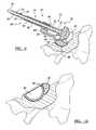
- FIG. 3is a perspective view of the reamer reaming an acetabulum according to an exemplary method of the present teachings
- FIG. 4is an installation view illustrating the reamer guide being assembled onto the reamer
- FIG. 5is a perspective view of an assembled tool approaching an acetabular socket to ream a defect adjacent the socket;
- FIG. 6is a perspective view of a locator member of the reamer guide positioning on the reamer socket while the reamer reams the defect according to the present teachings;
- FIG. 7is a perspective view of an exemplary acetabular cup and augment ready to be implanted at the implant site;
- FIG. 8is a perspective view of the exemplary acetabular cup and augment shown in an implanted position
- FIG. 9is a sectional view of the tool during reaming taken along line 9 - 9 of FIG. 6 ;
- FIG. 10is a sectional view of the acetabular cup and augment taken along line 10 - 10 of FIG. 8 ;
- FIG. 11is a plan view of a kit of reamers, reamer guides, and locator members.
- a tool for reaming an area of an acetabulumis shown and generally identified at reference numeral 10 .
- the tool 10generally includes a reamer 12 and a guide member or reamer guide 14 .
- the tool 10may be used to ream an area of the acetabulum having a defect.
- the reamer guide 14may be used to positively locate or reference at a first location, such as within an acetabular cavity, while the reamer 12 is used to ream a second location, such as the defect.
- the reamer 12may generally define a longitudinal shaft 18 having a proximal end and a distal end 20 and 22 , respectively.
- the proximal end 20may define mating structure 34 for coupling with a driver during operation.
- driversmay include pneumatic drivers, manual drivers or others.
- the drivermay utilize a quick connect for securing at the mating structure 34 . It is appreciated that the driver may impart rotational force onto the mating structure 34 .
- the distal end 22may include a mounting collar 24 defining attachment structure for selectively receiving a cutting head 30 thereat.
- a hub 32may be formed near the distal end 22 .
- the attachment structuremay comprise any suitable mechanical coupling for securing the distal end 22 to the cutting head 30 .
- the rotational force of the drivermay be communicated to the cutting head 30 by way of a reamer drive shaft 36 within the longitudinal shaft 18 operably connecting the mating structure 34 with the cutting head 30 .
- a stop member 40may be provided intermediate the proximal and distal ends 20 and 22 . In one example, the stop member 40 may cooperate with the hub 32 to capture the reamer guide 14 therebetween during operation.
- the longitudinal shaft 18 of the reamer 12may slidably translate through the reamer guide 14 in a first direction (leftward as viewed from FIG. 1 ) until the stopper 40 engages a proximal surface 42 of the reamer guide 14 and in a second direction (rightward as viewed from FIG. 1 ) until the hub 32 engages a distal surface 46 of the reamer guide 14 .
- the stopper 40may be moveable between an operating position ( FIG. 1 ) and an assembly position (depressed, as shown in FIG. 4 ). In the operating position, the stopper 40 may sit proud on the longitudinal shaft 18 . In the assembly position, the stopper 40 may be moved to a location substantially flush with the longitudinal shaft 18 . In one example, the stopper 40 may be depressed manually such as with a thumb. In this way, the reamer guide 14 may be slidably installed from the proximal end 20 of the longitudinal shaft 18 and slid in a direction toward the cutting head 30 until the proximal surface 42 of the reamer guide 14 passes beyond the stopper 40 . Once the reamer guide 14 has sufficiently passed beyond the stopper 40 , the stopper 40 may return to the operating position.
- the stopper 40may define a pin having a biasing member 44 .
- the biasing member 44may normally bias the stopper 40 in the operating position.
- the stopper 40may be depressed in a direction toward the longitudinal shaft 18 thereby overcoming a bias of the biasing member 44 until the distal surface 46 of the reamer guide 14 passes over the stopper 40 .
- the biasing member 44may urge the stopper 40 outward and to the operating position. It is appreciated that the configuration of the stopper 40 is merely exemplary and that other arrangements are contemplated. It is further appreciated that the cutting head 30 shown is merely exemplary and that other cutting heads may be used.
- the reamer guide 14may be formed of rigid material such as polyethylene, metal, or other suitable material.
- the reamer guide 14generally includes a cannulated body 50 , an arm portion 52 and a locator member 54 .
- the cannulated body 50defines an opening 56 .
- the body 50may define a handle for a user to grasp during operation.
- the reamer guide 14may be one-piece.
- a collar 58is formed at a transition between the body 50 and the arm 52 . The collar 58 may extend at a right angle with respect to the body 50 .
- the arm 52may define a first section 60 arranged parallel to an axis defined by the longitudinal shaft 18 , a second section 62 arranged at an angle relative to the axis and a third section 64 arranged parallel to the first section 60 .
- Such a configurationpositions the locator member 54 offset relative to the cutting head 30 .
- each cannulated body 50 a and 50 bdefines a male oval insertion portion 66 a and 66 b , respectively.
- each male oval insertion portion 66 a and 66 bdefines an oval having a generally trapezoidal shape including a smaller side and a larger side.
- the opening 56 a of the body 50 ais aligned with the smaller side of the insertion portion 66 a whereas the opening 56 b of the body 50 b is aligned with the larger side of the insertion portion 66 b .
- the insertion portion 66 ais shown received into a complementary female receiving portion 67 defined on the collar 58 in FIG. 2C .
- the insertion portion 66 bis shown received into the complementary female receiving portion 67 in FIG. 2D .
- the body 50 bwill present a larger offset between the reamer 30 and the locator member 54 as compared to the body 50 a .
- the trapezoidal oval designrequires insertion into the female receiving portion 67 in only one orientation.
- the opening 56may be defined anywhere relative to the insertion portion 66 to provide a variety of desired offsets.
- other geometries and configurations of the body and collarmay be used to allow for various relative offsets.
- the locator member 54may define a spherical outer engaging surface 68 .
- the locator member 54may further define a concave recess 70 for accommodating the cutting head 30 in the assembled position, see e.g. FIGS. 2B and 5 .
- a kit 74 of guide members 18 , 18 ′, 18 ′′may be provided, each having selected geometrical characteristics.
- a set of guide members 18 , 18 ′, 18 ′′may each define arms 52 , 52 ′, 52 ′′ extending at various parallel offsets relative to the body 50 , 50 ′, 50 ′′.
- guide members having various locator members 54 , 54 ′, 54 ′′may be provided.
- the guide members 18 , 18 ′, 18 ′′may also comprise modular components.
- the body 50 , the arm portion 52 and/or the locator member 54may be separate components.
- various locator members 54 , 54 ′ and 54 ′′may be selectively attached to a handle portion 76 .
- the locator members 54 , 54 ′ and 54 ′′may secure to the handle portion by any suitable means such as a quick connect for example.
- a unitary locator member and arm portion 78 , 78 ′ and 78 ′′may be selectively attached to a handle portion 50 .
- a surgeonmay assemble a desired tool having characteristics suitable for a given patient.
- the kit 7may also provide various cutting heads 30 , 30 ′.
- the primary acetabular cupmay be removed.
- An acetabulum 80may then be reamed such as with the reamer 12 .
- a surgeonmay determine a suitable cutting member 30 , 30 ′ ( FIG. 11 ) for a given patient.
- a driver(not shown) may be operably coupled with the mating structure 34 to impart rotational force through a reamer drive shaft 36 to the cutting head 30 .
- the acetabulum 80may be generally hemispherically reamed until concentric removal of all acetabular cartilage and/or bone cement is achieved.
- acetabular trial gauges(not shown), which are well known in the art, may be used to determine and confirm the diameter of the acetabular cup to be used.
- a surgeonmay access the defect to be reamed and identify which reamer guide 52 , 52 ′, 52 ′′ ( FIG. 11 ), body 50 a - 50 b ′′, or which handle 76 and locator members 54 , 54 ′, 54 ′′ to select for achieving the proper reaming area.
- the reamer guide 14may be slidably inserted onto the longitudinal shaft 18 of the reamer 12 .
- the drivermay be disconnected from the mating structure 34 and the opening 56 of the reamer guide 14 advanced onto the proximal end 20 of the longitudinal shaft 18 ( FIG. 4 ).
- the reamer guide 14may be further advanced toward the distal end 22 of the longitudinal shaft 18 .
- itmay be necessary to manually depress the stopper 40 to allow the body 50 of the reamer guide 14 to initially pass over the stopper 40 .
- the force of the reamer guide 14may sufficiently depress the stopper 40 concurrently while being advanced into the operating position.
- the opening 56may be slightly tapered at the collar 58 to facilitate initial sliding of the reamer guide 14 over the stopper 40 . Once the reamer guide 14 passes completely over the stopper 40 , the stopper 40 may return to its outward position by way of the biasing member 44 .
- the tool 10is in the assembled position and ready for use.
- the reamer guide 14 of the tool 10may be used to positively locate the reamer 12 within a socket 84 of the acetabulum 80 while reaming a defect 86 identified adjacent the socket 84 of the acetabulum.
- the locator member 54may be located in a nested position within the socket 84 of the reamed acetabulum 80 ( FIG. 6 ). It is appreciated that the locator member 54 may be generally located against the socket 84 at a location opposite of the defect 86 . Once the locator member 54 is in a secure position within the socket 84 , the defect 86 may be reamed.
- a surgeonmay grasp the body 50 of the guide member 14 with one hand and grasp the longitudinal shaft 18 of the reamer 12 with the other hand. The surgeon may advance the longitudinal shaft 18 of the reamer 12 through the opening 56 of the reamer guide 14 .
- translation of the reamer 12may be limited between the stopper 40 and the hub 32 .
- various reamer guides 14may be provided that each define a specific length.
- a surgeonmay preselect a reamer guide 14 that limits a reaming depth to a specified distance according to a given patient.
- the stopper 40may be located in a position to preclude the reamer 30 from attaining a parallel relationship with the locator member 54 .
- translation of the reamer 30 along its axismay be limited to a location wherein a plane defined at the tip of the reamer 30 normal to the drive shaft 36 intersects the locator member 54 .
- an acetabular cup 90 and augment 92may be implanted.
- Exemplary acetabular cups and augmentsmay be found in co-pending application, U.S. Ser. No. 11/357,868, filed Feb. 17, 2006, entitled “Method and Apparatus for use of Porous Implants” also assigned to Biomet, Inc., of Warsaw Ind., which is incorporated herein by reference.
- the cup 90may be impanted at the socket 84 and the augment 92 may be implanted at the reamed defect site.
- the cup 90 and augment 92may be implanted by any suitable method.
- an impacting instrument(not shown) may be used to properly position the acetabular cup 90 .
- the impacting instrumentmay be threadably secured to an apical hole 94 of the acetabular cup.
- the inserting instrumentmay be solidly impacted to fully seat the acetabular cup 90 , such that firm rim fixation is achieved.
- the inserting instrumentmay be carefully removed from the cup 90 .
- a plurality of bone screw holesmay be bored through holes 96 in the acetabular cup 90 .
- a depth gaugeas is also known in the art, may be used to determine the length of the fixation screws. With the length of the screws determined, a fixation screw or multiple screws (not shown) may be inserted into screw holes 96 . Fixation screws (not shown) may be similarly used though bores 98 in the augment 92 to secure the augment.
Landscapes
- Health & Medical Sciences (AREA)
- Surgery (AREA)
- Life Sciences & Earth Sciences (AREA)
- Biomedical Technology (AREA)
- Medical Informatics (AREA)
- Orthopedic Medicine & Surgery (AREA)
- Oral & Maxillofacial Surgery (AREA)
- Engineering & Computer Science (AREA)
- Dentistry (AREA)
- Heart & Thoracic Surgery (AREA)
- Nuclear Medicine, Radiotherapy & Molecular Imaging (AREA)
- Molecular Biology (AREA)
- Animal Behavior & Ethology (AREA)
- General Health & Medical Sciences (AREA)
- Public Health (AREA)
- Veterinary Medicine (AREA)
- Surgical Instruments (AREA)
- Prostheses (AREA)
Abstract
Description
Claims (20)
Priority Applications (1)
| Application Number | Priority Date | Filing Date | Title |
|---|---|---|---|
| US11/453,312US7670343B2 (en) | 2006-06-14 | 2006-06-14 | Method and apparatus for reaming an acetabulum |
Applications Claiming Priority (1)
| Application Number | Priority Date | Filing Date | Title |
|---|---|---|---|
| US11/453,312US7670343B2 (en) | 2006-06-14 | 2006-06-14 | Method and apparatus for reaming an acetabulum |
Publications (2)
| Publication Number | Publication Date |
|---|---|
| US20080009874A1 US20080009874A1 (en) | 2008-01-10 |
| US7670343B2true US7670343B2 (en) | 2010-03-02 |
Family
ID=38919995
Family Applications (1)
| Application Number | Title | Priority Date | Filing Date |
|---|---|---|---|
| US11/453,312Expired - Fee RelatedUS7670343B2 (en) | 2006-06-14 | 2006-06-14 | Method and apparatus for reaming an acetabulum |
Country Status (1)
| Country | Link |
|---|---|
| US (1) | US7670343B2 (en) |
Cited By (12)
| Publication number | Priority date | Publication date | Assignee | Title |
|---|---|---|---|---|
| US20130218161A1 (en)* | 2011-08-25 | 2013-08-22 | The Cleveland Clinic Foundation | Method and apparatus for material removal |
| CN103735298A (en)* | 2013-12-31 | 2014-04-23 | 张文涛 | Acetabulum bone cutting device, combined bone extraction cutter and grinding mould |
| US20160143650A1 (en)* | 2014-11-20 | 2016-05-26 | Zimmer, Inc. | Surgical tool with shroud and alignment feature |
| US9814470B2 (en) | 2014-05-22 | 2017-11-14 | Symmetry Medical Manufacturing, Inc. | Offset orthopaedic reamer handle |
| US9861376B2 (en)* | 2011-01-28 | 2018-01-09 | DePuy Synthes Products, Inc. | Oscillating rasp for use in an orthopaedic surgical procedure |
| AU2015301641B2 (en)* | 2014-08-14 | 2019-11-21 | Biomet Manufacturing, Llc. | Flexible bone reamer |
| US11033341B2 (en) | 2017-05-10 | 2021-06-15 | Mako Surgical Corp. | Robotic spine surgery system and methods |
| US11065069B2 (en) | 2017-05-10 | 2021-07-20 | Mako Surgical Corp. | Robotic spine surgery system and methods |
| US20210267609A1 (en)* | 2020-03-02 | 2021-09-02 | Orthosoft Ulc | Systems and methods for co-operative control of robotically-positioned surgical instruments |
| US11234775B2 (en) | 2018-01-26 | 2022-02-01 | Mako Surgical Corp. | End effectors, systems, and methods for impacting prosthetics guided by surgical robots |
| US11395741B2 (en) | 2019-05-16 | 2022-07-26 | Howmedica Osteonics Corp. | Joint replacement augments and associated instrumentation |
| US11925362B2 (en) | 2021-12-10 | 2024-03-12 | Depuy Ireland Unlimited Company | Augment reamer and related methods |
Families Citing this family (57)
| Publication number | Priority date | Publication date | Assignee | Title |
|---|---|---|---|---|
| US10278711B2 (en) | 2006-02-27 | 2019-05-07 | Biomet Manufacturing, Llc | Patient-specific femoral guide |
| US9918740B2 (en) | 2006-02-27 | 2018-03-20 | Biomet Manufacturing, Llc | Backup surgical instrument system and method |
| US9173661B2 (en) | 2006-02-27 | 2015-11-03 | Biomet Manufacturing, Llc | Patient specific alignment guide with cutting surface and laser indicator |
| US8608749B2 (en)* | 2006-02-27 | 2013-12-17 | Biomet Manufacturing, Llc | Patient-specific acetabular guides and associated instruments |
| US9113971B2 (en)* | 2006-02-27 | 2015-08-25 | Biomet Manufacturing, Llc | Femoral acetabular impingement guide |
| US8568487B2 (en)* | 2006-02-27 | 2013-10-29 | Biomet Manufacturing, Llc | Patient-specific hip joint devices |
| US9339278B2 (en) | 2006-02-27 | 2016-05-17 | Biomet Manufacturing, Llc | Patient-specific acetabular guides and associated instruments |
| US8591516B2 (en) | 2006-02-27 | 2013-11-26 | Biomet Manufacturing, Llc | Patient-specific orthopedic instruments |
| US9289253B2 (en) | 2006-02-27 | 2016-03-22 | Biomet Manufacturing, Llc | Patient-specific shoulder guide |
| US9345548B2 (en) | 2006-02-27 | 2016-05-24 | Biomet Manufacturing, Llc | Patient-specific pre-operative planning |
| US20150335438A1 (en) | 2006-02-27 | 2015-11-26 | Biomet Manufacturing, Llc. | Patient-specific augments |
| US9907659B2 (en) | 2007-04-17 | 2018-03-06 | Biomet Manufacturing, Llc | Method and apparatus for manufacturing an implant |
| US8407067B2 (en) | 2007-04-17 | 2013-03-26 | Biomet Manufacturing Corp. | Method and apparatus for manufacturing an implant |
| US8603180B2 (en)* | 2006-02-27 | 2013-12-10 | Biomet Manufacturing, Llc | Patient-specific acetabular alignment guides |
| US9795399B2 (en) | 2006-06-09 | 2017-10-24 | Biomet Manufacturing, Llc | Patient-specific knee alignment guide and associated method |
| CA2781407A1 (en) | 2008-01-14 | 2009-07-23 | Michael P. Brenzel | Apparatus and methods for fracture repair |
| US7993408B2 (en)* | 2008-02-12 | 2011-08-09 | Biomet Manufacturing Corp. | Acetabular cup having an adjustable modular augment |
| US20090240256A1 (en)* | 2008-03-19 | 2009-09-24 | Biomet Manufacturing Corp. | Method And Apparatus For Implanting an Augment |
| US8556901B2 (en) | 2009-12-31 | 2013-10-15 | DePuy Synthes Products, LLC | Reciprocating rasps for use in an orthopaedic surgical procedure |
| US20110178520A1 (en) | 2010-01-15 | 2011-07-21 | Kyle Taylor | Rotary-rigid orthopaedic rod |
| WO2011091052A1 (en) | 2010-01-20 | 2011-07-28 | Kyle Taylor | Apparatus and methods for bone access and cavity preparation |
| WO2011112615A1 (en) | 2010-03-08 | 2011-09-15 | Krinke Todd A | Apparatus and methods for securing a bone implant |
| CA2829196A1 (en)* | 2010-03-08 | 2011-09-15 | Conventus Orthopaedics, Inc. | Apparatus and methods for bone repair |
| GB201009116D0 (en) | 2010-06-01 | 2010-07-14 | Materialise Nv | Acetabular cup reamer |
| US8808302B2 (en)* | 2010-08-12 | 2014-08-19 | DePuy Synthes Products, LLC | Customized patient-specific acetabular orthopaedic surgical instrument and method of use and fabrication |
| WO2012021857A2 (en)* | 2010-08-13 | 2012-02-16 | Mason James Bettenga | Surgical guides |
| CN103458804B (en)* | 2010-08-16 | 2016-12-21 | 史密夫和内修有限公司 | Systems and methods for modifying the surface of bone |
| US9271744B2 (en) | 2010-09-29 | 2016-03-01 | Biomet Manufacturing, Llc | Patient-specific guide for partial acetabular socket replacement |
| US9968376B2 (en) | 2010-11-29 | 2018-05-15 | Biomet Manufacturing, Llc | Patient-specific orthopedic instruments |
| DE102010054663B3 (en)* | 2010-12-15 | 2012-06-28 | Heraeus Medical Gmbh | Mold for molding a hip socket |
| US9241745B2 (en) | 2011-03-07 | 2016-01-26 | Biomet Manufacturing, Llc | Patient-specific femoral version guide |
| JP2014519877A (en)* | 2011-05-09 | 2014-08-21 | スミス アンド ネフュー インコーポレーテッド | Patient-specific equipment |
| US8597365B2 (en) | 2011-08-04 | 2013-12-03 | Biomet Manufacturing, Llc | Patient-specific pelvic implants for acetabular reconstruction |
| US9386993B2 (en) | 2011-09-29 | 2016-07-12 | Biomet Manufacturing, Llc | Patient-specific femoroacetabular impingement instruments and methods |
| WO2013046172A1 (en)* | 2011-09-30 | 2013-04-04 | Custom Med Orthopaedics Proprietary Limited | An orthopaedic apparatus |
| EP2586387A1 (en)* | 2011-10-31 | 2013-05-01 | Tornier Orthopedics Ireland Ltd. | Bone reamer |
| US9408613B2 (en) | 2011-12-13 | 2016-08-09 | Biomet Manufacturing, Llc | Glenoid reamer |
| US20140175027A1 (en)* | 2012-12-21 | 2014-06-26 | United Technologies Corporation | Fuel system with electrically heated filter screen |
| USD732165S1 (en)* | 2013-05-20 | 2015-06-16 | Hpf Spa | Combined milling tool and attachment for a surgery instrument for prosthetic surgery operations |
| US9668760B2 (en)* | 2013-08-08 | 2017-06-06 | Scott Kelley | Methods and systems for preparing the acetabulum to receive an acetabular component in a hip replacement surgical procedure |
| DE102013112497A1 (en)* | 2013-11-13 | 2015-05-13 | Aesculap Ag | Medical Instrument |
| CN105939677A (en) | 2013-12-12 | 2016-09-14 | 康文图斯整形外科公司 | Tissue displacement tools and methods |
| DE102014208283B4 (en)* | 2014-05-02 | 2019-01-10 | Peter Brehm | Apparatus for attaching a positioning means to a patient's bone, apparatus for processing a patient's bone and hip implant system |
| CN104688297A (en)* | 2015-03-26 | 2015-06-10 | 常州玛斯特精密工具有限公司 | Acetabular bone file |
| US10034753B2 (en) | 2015-10-22 | 2018-07-31 | DePuy Synthes Products, Inc. | Customized patient-specific orthopaedic instruments for component placement in a total hip arthroplasty |
| TWI601511B (en)* | 2016-01-19 | 2017-10-11 | 王子康 | Method and apparatus for hip replacement |
| EP4349282A3 (en)* | 2016-07-08 | 2024-10-09 | Biomet Manufacturing, LLC | Reamer and guide for glenoid augment preparation |
| US10722310B2 (en) | 2017-03-13 | 2020-07-28 | Zimmer Biomet CMF and Thoracic, LLC | Virtual surgery planning system and method |
| WO2019010252A2 (en) | 2017-07-04 | 2019-01-10 | Conventus Orthopaedics, Inc. | APPARATUS AND METHODS FOR TREATING BONES |
| CN107736916A (en)* | 2017-11-14 | 2018-02-27 | 北京市春立正达医疗器械股份有限公司 | Reamer for hip arthroplasty,acetabulum holds locator |
| EP3692932A1 (en)* | 2019-02-07 | 2020-08-12 | Hpf S.R.L. | Multifunction device |
| IT201900001801A1 (en)* | 2019-02-07 | 2020-08-07 | Hpf S R L | MULTIFUNCTIONAL DEVICE FOR PROSTHETIC SURGERY AND RELATIVE METHOD OF USE |
| US11083585B2 (en) | 2019-05-09 | 2021-08-10 | Howmedica Osteonics Corp. | Spring retained femoral augment |
| US11246604B2 (en) | 2019-10-02 | 2022-02-15 | Arthrex, Inc. | Reaming assemblies for preparation of surgical sites |
| US11160562B2 (en) | 2020-01-09 | 2021-11-02 | Arthrex, Inc. | Assemblies for preparation of surgical sites |
| US12419689B2 (en) | 2021-06-29 | 2025-09-23 | DePuy Synthes Products, Inc. | Patient-specific registration jig and associated method for registering an orthopaedic surgical instrument to a patient |
| US20230248539A1 (en) | 2022-02-07 | 2023-08-10 | Microport Orthopedics Holdings Inc. | Acetabular cup remover assembly |
Citations (74)
| Publication number | Priority date | Publication date | Assignee | Title |
|---|---|---|---|---|
| US1950362A (en)* | 1932-02-08 | 1934-03-06 | Champion De Arment Tool Compan | Tool |
| US3744061A (en) | 1971-09-13 | 1973-07-10 | H Frost | Artificial hip joint and method of implanting in a patient |
| US3891997A (en) | 1974-02-20 | 1975-07-01 | Jean Jules Marie Ernes Herbert | Hip-joint prosthesis |
| GB1409051A (en) | 1971-09-24 | 1975-10-08 | Nat Research Department Corp | Hip joint prostheses |
| FR2516377A1 (en) | 1981-11-13 | 1983-05-20 | Breard Francis | Artificial hip joint socket - has external face joined to cavity wall by spherical sector with grooved outer surface |
| EP0091315A1 (en) | 1982-04-07 | 1983-10-12 | National Research Development Corporation | Endoprosthetic bone joint devices |
| CH644511A5 (en) | 1980-04-28 | 1984-08-15 | Sulzer Ag | Acetabulum |
| DE3406357A1 (en) | 1983-06-07 | 1984-12-13 | Gebrüder Sulzer AG, Winterthur | Acetabulum which can be anchored without cement |
| US4528980A (en) | 1983-10-19 | 1985-07-16 | Howmedica, Inc. | Acetabulum sizer and drill guide |
| US4611587A (en) | 1984-09-24 | 1986-09-16 | Powlan Roy Y | Device for cutting threads in the walls of the acetabular cavity in humans |
| EP0205132A2 (en) | 1985-06-08 | 1986-12-17 | GMT Gesellschaft für medizinische Technik mbH | Cup for an artificial hip joint |
| US4634444A (en) | 1984-02-09 | 1987-01-06 | Joint Medical Products Corporation | Semi-constrained artificial joint |
| US4662891A (en) | 1983-11-21 | 1987-05-05 | Joint Medical Products Corporation | Fixation elements for artificial joints |
| US4678472A (en) | 1983-03-08 | 1987-07-07 | Joint Medical Products Corporation | Ball and socket bearing for artificial joint |
| US4695282A (en) | 1986-01-23 | 1987-09-22 | Osteonics Corp. | Acetabular cup assembly with selective bearing face orientation |
| US4704127A (en) | 1986-01-23 | 1987-11-03 | Osteonics Corp. | Dual-geometry acetabular cup component and method of implant |
| US4711233A (en) | 1985-06-26 | 1987-12-08 | Brown Byron L | Method and apparatus for cementing an acetabular cup to an acetabulum |
| US4712951A (en) | 1985-08-26 | 1987-12-15 | Brown Byron L | Tool for cutting annular groove |
| USD296714S (en) | 1986-01-23 | 1988-07-12 | Osteonics Corp. | Acetabular shell |
| US4777942A (en) | 1986-10-02 | 1988-10-18 | Sulzer Brothers Limited | Bone milling instrument |
| US4798610A (en) | 1982-09-29 | 1989-01-17 | Osteonics Corp. | Prosthetic implant device |
| US4801301A (en) | 1983-03-08 | 1989-01-31 | Joint Medical Products Corporation | Ball and socket bearing for artificial joint |
| EP0303006A1 (en) | 1987-08-13 | 1989-02-15 | Howmedica GmbH | Acetabular cup for a hip joint endoprosthesis |
| EP0309363A1 (en) | 1986-04-04 | 1989-03-29 | Claude Demeulenaere | Hip prosthesis |
| US4846839A (en) | 1984-02-09 | 1989-07-11 | Joint Medical Products Corporation | Apparatus for affixing a prosthesis to bone |
| US4856503A (en) | 1987-08-15 | 1989-08-15 | Orthoplant Endoprothetik Gmbh | Device for cutting a thread in a cup-shaped bone |
| US4865603A (en) | 1988-02-04 | 1989-09-12 | Joint Medical Products Corporation | Metallic prosthetic devices having micro-textured outer surfaces |
| US4871368A (en) | 1987-03-30 | 1989-10-03 | Sulzer Brothers Limited | Artifical acetabulum |
| US4883491A (en) | 1986-01-21 | 1989-11-28 | Joint Medical Products Corporation | Porous-coated artificial joints |
| US4892549A (en) | 1989-01-31 | 1990-01-09 | Osteonics Corp. | Dual-radius acetabular cup component |
| SU1561975A1 (en) | 1988-04-22 | 1990-05-07 | Б. Г. Зимлицкий и Е. Д. Соломко | Endoprosthesis of hip joint cotyloid cavity |
| US4950299A (en) | 1983-03-08 | 1990-08-21 | Joint Medical Products Corporation | Ball and socket bearing for artificial joint |
| US4960427A (en) | 1983-03-08 | 1990-10-02 | Joint Medical Products Corporation | Ball and socket bearing for artifical joint |
| US4963154A (en) | 1988-06-06 | 1990-10-16 | Mecron Medizinische Produkte Gmbh | Acetabular cup as part of a hip joint prosthesis |
| US4978356A (en) | 1983-03-08 | 1990-12-18 | Joint Medical Products Corporation | Ball and socket bearing for artificial joint |
| US4986147A (en)* | 1989-07-20 | 1991-01-22 | National Hand Tool Corporation | Ratchet wrench having an internally reinforced handle |
| SU1630799A1 (en) | 1989-03-20 | 1991-02-28 | Ленинградский научно-исследовательский институт травматологии и ортопедии им.Р.Р.Вредена | Device for making a socket in the hip bone |
| US5021063A (en) | 1988-02-11 | 1991-06-04 | Howmedica, Gmbh | Joint socket member for a joint prosthesis |
| US5030219A (en) | 1990-01-22 | 1991-07-09 | Boehringer Mannheim Corporation | Glenoid component installation tools |
| US5100409A (en) | 1991-03-07 | 1992-03-31 | Dow Corning Wright Corporation | Shaping and trial reduction guide for implantation of femoral prosthesis and method of using same |
| US5116165A (en) | 1991-03-11 | 1992-05-26 | Othy, Inc. | Acetabular reamer cup |
| US5176710A (en) | 1991-01-23 | 1993-01-05 | Orthopaedic Research Institute | Prosthesis with low stiffness factor |
| US5176711A (en) | 1991-03-06 | 1993-01-05 | Grimes James B | Acetabular revision system |
| US5192329A (en) | 1991-03-07 | 1993-03-09 | Joint Medical Products Corporation | Oblong acetabular cup |
| US5282864A (en) | 1992-02-19 | 1994-02-01 | Joint Medical Products Corporation | Acetabular prosthesis having a metal socket bearing |
| US5312411A (en) | 1992-10-27 | 1994-05-17 | Smith & Nephew Richards, Inc. | Uni-compartmental femoral knee instruments and prosthesis |
| US5358532A (en) | 1992-06-16 | 1994-10-25 | Smith & Nephew Richards Inc. | Cementless acetabular cup |
| US5437677A (en) | 1992-10-09 | 1995-08-01 | Minnesota Mining And Manufacturing Company | Glenoid alignment guide |
| US5468243A (en) | 1993-10-27 | 1995-11-21 | Halpern; Alan A. | Femoral superior neck remodelling means and method |
| US5496324A (en) | 1994-06-20 | 1996-03-05 | Zimmer, Inc. | Proximal body milling apparatus |
| US5549701A (en) | 1993-09-20 | 1996-08-27 | Mikhail; W. E. Michael | Acetabular cup |
| US5549698A (en) | 1993-04-22 | 1996-08-27 | Implex Corp. | Prosthetic acetabular cup and method of implant |
| US5549694A (en) | 1994-07-25 | 1996-08-27 | Joint Medical Products Corporation | Acetabular prosthesis with apertures sealed with deformable discs and method |
| US5549697A (en) | 1994-09-22 | 1996-08-27 | Johnson & Johnson Professional, Inc. | Hip joint prostheses and methods for manufacturing the same |
| US5624447A (en) | 1995-03-20 | 1997-04-29 | Othy, Inc. | Surgical tool guide and entry hole positioner |
| US5669915A (en) | 1995-03-22 | 1997-09-23 | Aesculap Ag | Drilling jig for surgical drilling tools |
| US5676704A (en) | 1995-11-27 | 1997-10-14 | Smith & Nephew, Inc. | Acetabular cup body prosthesis |
| US5733289A (en) | 1992-10-27 | 1998-03-31 | Neoligaments Limited | Ligament graft harvesting |
| US5769856A (en) | 1996-06-24 | 1998-06-23 | Osteonics Corp. | Drill guide and implant method |
| US5792044A (en)* | 1996-03-22 | 1998-08-11 | Danek Medical, Inc. | Devices and methods for percutaneous surgery |
| US5895389A (en) | 1997-05-29 | 1999-04-20 | Synthes (U.S.A.) | Drilling guide and measuring instrumentation |
| US5919195A (en)* | 1998-01-20 | 1999-07-06 | Johnson & Johnson Professional, Inc. | Oblong acetabular component instrumentation |
| US5928288A (en) | 1998-05-13 | 1999-07-27 | Johnson & Johnson Professional, Inc. | Variable fit oblong acetabular prosthesis |
| US5961530A (en) | 1992-06-08 | 1999-10-05 | Orthopedic Systems, Inc. | Apparatus for attaching suture to bone |
| US5976145A (en) | 1998-06-01 | 1999-11-02 | Johnson & Johnson Professional, Inc. | Calcar milling guide and system |
| US6102915A (en) | 1996-02-13 | 2000-08-15 | Advanced Technical Fabrication | Hip prosthesis positioning instrument |
| US6245074B1 (en) | 1999-09-01 | 2001-06-12 | Bristol-Myers Squibb Co. | Orthopaedic glenoid reamer |
| US6273891B1 (en) | 1997-02-11 | 2001-08-14 | Medidea Llc | Method and apparatus for aligning a prosthetic element |
| US6395005B1 (en) | 2000-04-14 | 2002-05-28 | Howmedica Osteonics Corp. | Acetabular alignment apparatus and method |
| US6416553B1 (en) | 1999-03-31 | 2002-07-09 | Biomet, Inc. | Method and apparatus for providing a modular acetabular prosthesis |
| US6673115B2 (en) | 1997-09-09 | 2004-01-06 | Stryker Technologies Corporation | Anatomic glenoid shoulder prosthesis together with methods and tools for implanting same |
| US6682567B1 (en) | 2001-09-19 | 2004-01-27 | Biomet, Inc. | Method and apparatus for providing a shell component incorporating a porous ingrowth material and liner |
| US6702822B1 (en) | 1996-01-04 | 2004-03-09 | Joint Medical Products Corporation | Method and apparatus for fitting a prosthesis to a bone |
| US6875218B2 (en) | 2002-06-10 | 2005-04-05 | Zimmer Austin, Inc. | Elongated driving bit attachable to a driving instrument and method of use for minimally invasive hip surgery |
- 2006
- 2006-06-14USUS11/453,312patent/US7670343B2/ennot_activeExpired - Fee Related
Patent Citations (80)
| Publication number | Priority date | Publication date | Assignee | Title |
|---|---|---|---|---|
| US1950362A (en)* | 1932-02-08 | 1934-03-06 | Champion De Arment Tool Compan | Tool |
| US3744061A (en) | 1971-09-13 | 1973-07-10 | H Frost | Artificial hip joint and method of implanting in a patient |
| GB1409051A (en) | 1971-09-24 | 1975-10-08 | Nat Research Department Corp | Hip joint prostheses |
| US3891997A (en) | 1974-02-20 | 1975-07-01 | Jean Jules Marie Ernes Herbert | Hip-joint prosthesis |
| CH644511A5 (en) | 1980-04-28 | 1984-08-15 | Sulzer Ag | Acetabulum |
| FR2516377A1 (en) | 1981-11-13 | 1983-05-20 | Breard Francis | Artificial hip joint socket - has external face joined to cavity wall by spherical sector with grooved outer surface |
| EP0091315A1 (en) | 1982-04-07 | 1983-10-12 | National Research Development Corporation | Endoprosthetic bone joint devices |
| US4798610A (en) | 1982-09-29 | 1989-01-17 | Osteonics Corp. | Prosthetic implant device |
| US4978356A (en) | 1983-03-08 | 1990-12-18 | Joint Medical Products Corporation | Ball and socket bearing for artificial joint |
| US4801301A (en) | 1983-03-08 | 1989-01-31 | Joint Medical Products Corporation | Ball and socket bearing for artificial joint |
| US4950299A (en) | 1983-03-08 | 1990-08-21 | Joint Medical Products Corporation | Ball and socket bearing for artificial joint |
| US4960427A (en) | 1983-03-08 | 1990-10-02 | Joint Medical Products Corporation | Ball and socket bearing for artifical joint |
| US4678472A (en) | 1983-03-08 | 1987-07-07 | Joint Medical Products Corporation | Ball and socket bearing for artificial joint |
| DE3406357A1 (en) | 1983-06-07 | 1984-12-13 | Gebrüder Sulzer AG, Winterthur | Acetabulum which can be anchored without cement |
| US4528980A (en) | 1983-10-19 | 1985-07-16 | Howmedica, Inc. | Acetabulum sizer and drill guide |
| US4662891A (en) | 1983-11-21 | 1987-05-05 | Joint Medical Products Corporation | Fixation elements for artificial joints |
| US4634444A (en) | 1984-02-09 | 1987-01-06 | Joint Medical Products Corporation | Semi-constrained artificial joint |
| US4846839A (en) | 1984-02-09 | 1989-07-11 | Joint Medical Products Corporation | Apparatus for affixing a prosthesis to bone |
| US4611587A (en) | 1984-09-24 | 1986-09-16 | Powlan Roy Y | Device for cutting threads in the walls of the acetabular cavity in humans |
| EP0205132A2 (en) | 1985-06-08 | 1986-12-17 | GMT Gesellschaft für medizinische Technik mbH | Cup for an artificial hip joint |
| US4711233A (en) | 1985-06-26 | 1987-12-08 | Brown Byron L | Method and apparatus for cementing an acetabular cup to an acetabulum |
| US4712951A (en) | 1985-08-26 | 1987-12-15 | Brown Byron L | Tool for cutting annular groove |
| US4944759A (en) | 1986-01-21 | 1990-07-31 | Joint Medical Products Corporation | Porous-coated artificial joints |
| US4883491A (en) | 1986-01-21 | 1989-11-28 | Joint Medical Products Corporation | Porous-coated artificial joints |
| USD296714S (en) | 1986-01-23 | 1988-07-12 | Osteonics Corp. | Acetabular shell |
| US4695282A (en) | 1986-01-23 | 1987-09-22 | Osteonics Corp. | Acetabular cup assembly with selective bearing face orientation |
| US4704127A (en) | 1986-01-23 | 1987-11-03 | Osteonics Corp. | Dual-geometry acetabular cup component and method of implant |
| EP0309363A1 (en) | 1986-04-04 | 1989-03-29 | Claude Demeulenaere | Hip prosthesis |
| US4777942A (en) | 1986-10-02 | 1988-10-18 | Sulzer Brothers Limited | Bone milling instrument |
| US4871368A (en) | 1987-03-30 | 1989-10-03 | Sulzer Brothers Limited | Artifical acetabulum |
| EP0303006A1 (en) | 1987-08-13 | 1989-02-15 | Howmedica GmbH | Acetabular cup for a hip joint endoprosthesis |
| US4856503A (en) | 1987-08-15 | 1989-08-15 | Orthoplant Endoprothetik Gmbh | Device for cutting a thread in a cup-shaped bone |
| US4865603A (en) | 1988-02-04 | 1989-09-12 | Joint Medical Products Corporation | Metallic prosthetic devices having micro-textured outer surfaces |
| US5021063A (en) | 1988-02-11 | 1991-06-04 | Howmedica, Gmbh | Joint socket member for a joint prosthesis |
| SU1561975A1 (en) | 1988-04-22 | 1990-05-07 | Б. Г. Зимлицкий и Е. Д. Соломко | Endoprosthesis of hip joint cotyloid cavity |
| US4963154A (en) | 1988-06-06 | 1990-10-16 | Mecron Medizinische Produkte Gmbh | Acetabular cup as part of a hip joint prosthesis |
| US4892549A (en) | 1989-01-31 | 1990-01-09 | Osteonics Corp. | Dual-radius acetabular cup component |
| US4892549B1 (en) | 1989-01-31 | 1999-10-05 | Stryker Corp | Dual-radius acetubular cup component |
| SU1630799A1 (en) | 1989-03-20 | 1991-02-28 | Ленинградский научно-исследовательский институт травматологии и ортопедии им.Р.Р.Вредена | Device for making a socket in the hip bone |
| US4986147A (en)* | 1989-07-20 | 1991-01-22 | National Hand Tool Corporation | Ratchet wrench having an internally reinforced handle |
| US5030219A (en) | 1990-01-22 | 1991-07-09 | Boehringer Mannheim Corporation | Glenoid component installation tools |
| US5176710A (en) | 1991-01-23 | 1993-01-05 | Orthopaedic Research Institute | Prosthesis with low stiffness factor |
| US5176711A (en) | 1991-03-06 | 1993-01-05 | Grimes James B | Acetabular revision system |
| US5100409A (en) | 1991-03-07 | 1992-03-31 | Dow Corning Wright Corporation | Shaping and trial reduction guide for implantation of femoral prosthesis and method of using same |
| US5370704A (en) | 1991-03-07 | 1994-12-06 | Joint Medical Products Corporation | Oblong acetabular cup |
| US5290315A (en) | 1991-03-07 | 1994-03-01 | Joint Medical Products Corporation | Oblong acetabular cup |
| US5192329A (en) | 1991-03-07 | 1993-03-09 | Joint Medical Products Corporation | Oblong acetabular cup |
| US5116165A (en) | 1991-03-11 | 1992-05-26 | Othy, Inc. | Acetabular reamer cup |
| US5413603A (en) | 1992-02-19 | 1995-05-09 | Joint Medical Products Corporation | Taper-locked acetabular socket bearing |
| US5282864A (en) | 1992-02-19 | 1994-02-01 | Joint Medical Products Corporation | Acetabular prosthesis having a metal socket bearing |
| US5961530A (en) | 1992-06-08 | 1999-10-05 | Orthopedic Systems, Inc. | Apparatus for attaching suture to bone |
| US5358532A (en) | 1992-06-16 | 1994-10-25 | Smith & Nephew Richards Inc. | Cementless acetabular cup |
| US5437677A (en) | 1992-10-09 | 1995-08-01 | Minnesota Mining And Manufacturing Company | Glenoid alignment guide |
| US5733289A (en) | 1992-10-27 | 1998-03-31 | Neoligaments Limited | Ligament graft harvesting |
| US5312411A (en) | 1992-10-27 | 1994-05-17 | Smith & Nephew Richards, Inc. | Uni-compartmental femoral knee instruments and prosthesis |
| US5549698A (en) | 1993-04-22 | 1996-08-27 | Implex Corp. | Prosthetic acetabular cup and method of implant |
| US5571201A (en) | 1993-04-22 | 1996-11-05 | Implex Corporation | Prosthetic acetabular cup and method of implant |
| US5549701A (en) | 1993-09-20 | 1996-08-27 | Mikhail; W. E. Michael | Acetabular cup |
| US5468243A (en) | 1993-10-27 | 1995-11-21 | Halpern; Alan A. | Femoral superior neck remodelling means and method |
| US5496324A (en) | 1994-06-20 | 1996-03-05 | Zimmer, Inc. | Proximal body milling apparatus |
| US5549694A (en) | 1994-07-25 | 1996-08-27 | Joint Medical Products Corporation | Acetabular prosthesis with apertures sealed with deformable discs and method |
| US5549697A (en) | 1994-09-22 | 1996-08-27 | Johnson & Johnson Professional, Inc. | Hip joint prostheses and methods for manufacturing the same |
| US5624447A (en) | 1995-03-20 | 1997-04-29 | Othy, Inc. | Surgical tool guide and entry hole positioner |
| US5669915A (en) | 1995-03-22 | 1997-09-23 | Aesculap Ag | Drilling jig for surgical drilling tools |
| US5676704A (en) | 1995-11-27 | 1997-10-14 | Smith & Nephew, Inc. | Acetabular cup body prosthesis |
| US6702822B1 (en) | 1996-01-04 | 2004-03-09 | Joint Medical Products Corporation | Method and apparatus for fitting a prosthesis to a bone |
| US6102915A (en) | 1996-02-13 | 2000-08-15 | Advanced Technical Fabrication | Hip prosthesis positioning instrument |
| US5792044A (en)* | 1996-03-22 | 1998-08-11 | Danek Medical, Inc. | Devices and methods for percutaneous surgery |
| US5769856A (en) | 1996-06-24 | 1998-06-23 | Osteonics Corp. | Drill guide and implant method |
| US6273891B1 (en) | 1997-02-11 | 2001-08-14 | Medidea Llc | Method and apparatus for aligning a prosthetic element |
| US5895389A (en) | 1997-05-29 | 1999-04-20 | Synthes (U.S.A.) | Drilling guide and measuring instrumentation |
| US6673115B2 (en) | 1997-09-09 | 2004-01-06 | Stryker Technologies Corporation | Anatomic glenoid shoulder prosthesis together with methods and tools for implanting same |
| US5919195A (en)* | 1998-01-20 | 1999-07-06 | Johnson & Johnson Professional, Inc. | Oblong acetabular component instrumentation |
| US5928288A (en) | 1998-05-13 | 1999-07-27 | Johnson & Johnson Professional, Inc. | Variable fit oblong acetabular prosthesis |
| US5976145A (en) | 1998-06-01 | 1999-11-02 | Johnson & Johnson Professional, Inc. | Calcar milling guide and system |
| US6416553B1 (en) | 1999-03-31 | 2002-07-09 | Biomet, Inc. | Method and apparatus for providing a modular acetabular prosthesis |
| US6245074B1 (en) | 1999-09-01 | 2001-06-12 | Bristol-Myers Squibb Co. | Orthopaedic glenoid reamer |
| US6395005B1 (en) | 2000-04-14 | 2002-05-28 | Howmedica Osteonics Corp. | Acetabular alignment apparatus and method |
| US6682567B1 (en) | 2001-09-19 | 2004-01-27 | Biomet, Inc. | Method and apparatus for providing a shell component incorporating a porous ingrowth material and liner |
| US6875218B2 (en) | 2002-06-10 | 2005-04-05 | Zimmer Austin, Inc. | Elongated driving bit attachable to a driving instrument and method of use for minimally invasive hip surgery |
Cited By (23)
| Publication number | Priority date | Publication date | Assignee | Title |
|---|---|---|---|---|
| US9861376B2 (en)* | 2011-01-28 | 2018-01-09 | DePuy Synthes Products, Inc. | Oscillating rasp for use in an orthopaedic surgical procedure |
| US10159500B2 (en)* | 2011-01-28 | 2018-12-25 | DePuy Synthes Products, Inc. | Oscillating rasp for use in an orthopaedic surgical procedure |
| US20130218161A1 (en)* | 2011-08-25 | 2013-08-22 | The Cleveland Clinic Foundation | Method and apparatus for material removal |
| CN103735298A (en)* | 2013-12-31 | 2014-04-23 | 张文涛 | Acetabulum bone cutting device, combined bone extraction cutter and grinding mould |
| US11076869B2 (en) | 2014-05-22 | 2021-08-03 | Symmetry Medical Manufacturing, Inc. | Offset orthopaedic reamer handle |
| US9814470B2 (en) | 2014-05-22 | 2017-11-14 | Symmetry Medical Manufacturing, Inc. | Offset orthopaedic reamer handle |
| US11311301B2 (en) | 2014-08-14 | 2022-04-26 | Biomet Manufacturing, Llc | Flexible bone reamer |
| AU2015301641B2 (en)* | 2014-08-14 | 2019-11-21 | Biomet Manufacturing, Llc. | Flexible bone reamer |
| US10022133B2 (en)* | 2014-11-20 | 2018-07-17 | Zimmer, Inc. | Surgical tool with shroud and alignment feature |
| US20160143650A1 (en)* | 2014-11-20 | 2016-05-26 | Zimmer, Inc. | Surgical tool with shroud and alignment feature |
| US11937889B2 (en) | 2017-05-10 | 2024-03-26 | Mako Surgical Corp. | Robotic spine surgery system and methods |
| US11033341B2 (en) | 2017-05-10 | 2021-06-15 | Mako Surgical Corp. | Robotic spine surgery system and methods |
| US11701188B2 (en) | 2017-05-10 | 2023-07-18 | Mako Surgical Corp. | Robotic spine surgery system and methods |
| US11065069B2 (en) | 2017-05-10 | 2021-07-20 | Mako Surgical Corp. | Robotic spine surgery system and methods |
| US12035985B2 (en) | 2017-05-10 | 2024-07-16 | Mako Surgical Corp. | Robotic spine surgery system and methods |
| US11234775B2 (en) | 2018-01-26 | 2022-02-01 | Mako Surgical Corp. | End effectors, systems, and methods for impacting prosthetics guided by surgical robots |
| US12167899B2 (en) | 2018-01-26 | 2024-12-17 | Mako Surgical Corp. | Systems, methods, and end effectors for guiding prostheses |
| US11395741B2 (en) | 2019-05-16 | 2022-07-26 | Howmedica Osteonics Corp. | Joint replacement augments and associated instrumentation |
| US12350161B2 (en) | 2019-05-16 | 2025-07-08 | Howmedica Osteonics Corp. | Joint replacement augments and associated instrumentation |
| US20210267609A1 (en)* | 2020-03-02 | 2021-09-02 | Orthosoft Ulc | Systems and methods for co-operative control of robotically-positioned surgical instruments |
| US11801062B2 (en)* | 2020-03-02 | 2023-10-31 | Orthosoft Ulc | Systems and methods for co-operative control of robotically-positioned surgical instruments |
| US12193688B2 (en)* | 2020-03-02 | 2025-01-14 | Orthosoft Ulc | Systems and methods for co-operative control of robotically-positioned surgical instruments |
| US11925362B2 (en) | 2021-12-10 | 2024-03-12 | Depuy Ireland Unlimited Company | Augment reamer and related methods |
Also Published As
| Publication number | Publication date |
|---|---|
| US20080009874A1 (en) | 2008-01-10 |
Similar Documents
| Publication | Publication Date | Title |
|---|---|---|
| US7670343B2 (en) | Method and apparatus for reaming an acetabulum | |
| US11147691B2 (en) | Punch, implant and associated method | |
| US9687252B2 (en) | Femoral reaming system and method of performing trial reduction | |
| US7074224B2 (en) | Modular tapered reamer for bone preparation and associated method | |
| EP1813229B1 (en) | Split thread orthopaedic implant impactor | |
| US20060161167A1 (en) | Acetabular instrument alignment guide | |
| US8876837B2 (en) | Method and apparatus for implanting a modular femoral hip | |
| US20090240256A1 (en) | Method And Apparatus For Implanting an Augment | |
| EP1752105A1 (en) | Non-linear reamer for bone preparation | |
| CN104042310A (en) | Femoral Orthopaedic Instrument Assembly For Setting Offset | |
| CN104042256A (en) | Femoral orthopaedic surgical instruments for setting offset | |
| CN104042309A (en) | Femoral system handle surgical instrument and method of assembling same | |
| JP2005169084A (en) | Method and apparatus for positioning a humeral component during shoulder arthroplasty |
Legal Events
| Date | Code | Title | Description |
|---|---|---|---|
| AS | Assignment | Owner name:BIOMET MANUFACTURING CORP., INDIANA Free format text:ASSIGNMENT OF ASSIGNORS INTEREST;ASSIGNORS:MERIDEW, JASON D.;PARCHER, KIM S.;REEL/FRAME:018001/0709 Effective date:20060609 Owner name:BIOMET MANUFACTURING CORP.,INDIANA Free format text:ASSIGNMENT OF ASSIGNORS INTEREST;ASSIGNORS:MERIDEW, JASON D.;PARCHER, KIM S.;REEL/FRAME:018001/0709 Effective date:20060609 | |
| AS | Assignment | Owner name:BANK OF AMERICA, N.A., AS ADMINISTRATIVE AGENT FOR Free format text:SECURITY AGREEMENT;ASSIGNORS:LVB ACQUISITION, INC.;BIOMET, INC.;REEL/FRAME:020362/0001 Effective date:20070925 | |
| STCF | Information on status: patent grant | Free format text:PATENTED CASE | |
| FPAY | Fee payment | Year of fee payment:4 | |
| AS | Assignment | Owner name:BIOMET MANUFACTURING, LLC, INDIANA Free format text:CHANGE OF NAME;ASSIGNOR:BIOMET MANUFACTURING CORPORATION;REEL/FRAME:030656/0702 Effective date:20130603 | |
| AS | Assignment | Owner name:BIOMET, INC., INDIANA Free format text:RELEASE OF SECURITY INTEREST IN PATENTS RECORDED AT REEL 020362/ FRAME 0001;ASSIGNOR:BANK OF AMERICA, N.A., AS ADMINISTRATIVE AGENT;REEL/FRAME:037155/0133 Effective date:20150624 Owner name:LVB ACQUISITION, INC., INDIANA Free format text:RELEASE OF SECURITY INTEREST IN PATENTS RECORDED AT REEL 020362/ FRAME 0001;ASSIGNOR:BANK OF AMERICA, N.A., AS ADMINISTRATIVE AGENT;REEL/FRAME:037155/0133 Effective date:20150624 | |
| FPAY | Fee payment | Year of fee payment:8 | |
| FEPP | Fee payment procedure | Free format text:MAINTENANCE FEE REMINDER MAILED (ORIGINAL EVENT CODE: REM.); ENTITY STATUS OF PATENT OWNER: LARGE ENTITY | |
| LAPS | Lapse for failure to pay maintenance fees | Free format text:PATENT EXPIRED FOR FAILURE TO PAY MAINTENANCE FEES (ORIGINAL EVENT CODE: EXP.); ENTITY STATUS OF PATENT OWNER: LARGE ENTITY | |
| STCH | Information on status: patent discontinuation | Free format text:PATENT EXPIRED DUE TO NONPAYMENT OF MAINTENANCE FEES UNDER 37 CFR 1.362 | |
| FP | Lapsed due to failure to pay maintenance fee | Effective date:20220302 |