US7669816B2 - Clamp for mount system - Google Patents
Clamp for mount systemDownload PDFInfo
- Publication number
- US7669816B2 US7669816B2US11/107,441US10744105AUS7669816B2US 7669816 B2US7669816 B2US 7669816B2US 10744105 AUS10744105 AUS 10744105AUS 7669816 B2US7669816 B2US 7669816B2
- Authority
- US
- United States
- Prior art keywords
- support
- geomatics
- clamp
- clutch
- elastomeric pad
- Prior art date
- Legal status (The legal status is an assumption and is not a legal conclusion. Google has not performed a legal analysis and makes no representation as to the accuracy of the status listed.)
- Active, expires
Links
Images


Classifications
- G—PHYSICS
- G01—MEASURING; TESTING
- G01C—MEASURING DISTANCES, LEVELS OR BEARINGS; SURVEYING; NAVIGATION; GYROSCOPIC INSTRUMENTS; PHOTOGRAMMETRY OR VIDEOGRAMMETRY
- G01C15/00—Surveying instruments or accessories not provided for in groups G01C1/00 - G01C13/00
- F—MECHANICAL ENGINEERING; LIGHTING; HEATING; WEAPONS; BLASTING
- F16—ENGINEERING ELEMENTS AND UNITS; GENERAL MEASURES FOR PRODUCING AND MAINTAINING EFFECTIVE FUNCTIONING OF MACHINES OR INSTALLATIONS; THERMAL INSULATION IN GENERAL
- F16M—FRAMES, CASINGS OR BEDS OF ENGINES, MACHINES OR APPARATUS, NOT SPECIFIC TO ENGINES, MACHINES OR APPARATUS PROVIDED FOR ELSEWHERE; STANDS; SUPPORTS
- F16M11/00—Stands or trestles as supports for apparatus or articles placed thereon ; Stands for scientific apparatus such as gravitational force meters
- F16M11/02—Heads
- F16M11/04—Means for attachment of apparatus; Means allowing adjustment of the apparatus relatively to the stand
- F16M11/041—Allowing quick release of the apparatus
- F—MECHANICAL ENGINEERING; LIGHTING; HEATING; WEAPONS; BLASTING
- F16—ENGINEERING ELEMENTS AND UNITS; GENERAL MEASURES FOR PRODUCING AND MAINTAINING EFFECTIVE FUNCTIONING OF MACHINES OR INSTALLATIONS; THERMAL INSULATION IN GENERAL
- F16M—FRAMES, CASINGS OR BEDS OF ENGINES, MACHINES OR APPARATUS, NOT SPECIFIC TO ENGINES, MACHINES OR APPARATUS PROVIDED FOR ELSEWHERE; STANDS; SUPPORTS
- F16M11/00—Stands or trestles as supports for apparatus or articles placed thereon ; Stands for scientific apparatus such as gravitational force meters
- F16M11/02—Heads
- F16M11/04—Means for attachment of apparatus; Means allowing adjustment of the apparatus relatively to the stand
- F16M11/06—Means for attachment of apparatus; Means allowing adjustment of the apparatus relatively to the stand allowing pivoting
- F16M11/10—Means for attachment of apparatus; Means allowing adjustment of the apparatus relatively to the stand allowing pivoting around a horizontal axis
- F—MECHANICAL ENGINEERING; LIGHTING; HEATING; WEAPONS; BLASTING
- F16—ENGINEERING ELEMENTS AND UNITS; GENERAL MEASURES FOR PRODUCING AND MAINTAINING EFFECTIVE FUNCTIONING OF MACHINES OR INSTALLATIONS; THERMAL INSULATION IN GENERAL
- F16M—FRAMES, CASINGS OR BEDS OF ENGINES, MACHINES OR APPARATUS, NOT SPECIFIC TO ENGINES, MACHINES OR APPARATUS PROVIDED FOR ELSEWHERE; STANDS; SUPPORTS
- F16M13/00—Other supports for positioning apparatus or articles; Means for steadying hand-held apparatus or articles
- F16M13/02—Other supports for positioning apparatus or articles; Means for steadying hand-held apparatus or articles for supporting on, or attaching to, an object, e.g. tree, gate, window-frame, cycle
- F16M13/022—Other supports for positioning apparatus or articles; Means for steadying hand-held apparatus or articles for supporting on, or attaching to, an object, e.g. tree, gate, window-frame, cycle repositionable
- F—MECHANICAL ENGINEERING; LIGHTING; HEATING; WEAPONS; BLASTING
- F16—ENGINEERING ELEMENTS AND UNITS; GENERAL MEASURES FOR PRODUCING AND MAINTAINING EFFECTIVE FUNCTIONING OF MACHINES OR INSTALLATIONS; THERMAL INSULATION IN GENERAL
- F16M—FRAMES, CASINGS OR BEDS OF ENGINES, MACHINES OR APPARATUS, NOT SPECIFIC TO ENGINES, MACHINES OR APPARATUS PROVIDED FOR ELSEWHERE; STANDS; SUPPORTS
- F16M2200/00—Details of stands or supports
- F16M2200/02—Locking means
- F16M2200/025—Locking means for translational movement
- F16M2200/027—Locking means for translational movement by friction
Definitions
- This inventionrelates generally to devices that support and hold equipment and more particularly to a clamp for a mount system for holding handheld electrical devices.
- Handheld electrical devicessuch as handheld computers (e.g., data collectors, PDAs, BlackberrysTM) and cellular phones, are widely used and have many applications. For example, many land surveyors use handheld electrical data collectors to record and store field measurements, perform calculations, verify data accuracy, and even generate plots. Data collectors equipped for surveying can be connected directly to surveying equipment (e.g., a total station) for recording data and then to a PC or notebook computer for transferring the data from the data collector. Thus, data collectors allow surveyors to quickly, easily, and accurately collect surveying data and transfer it to a PC or notebook computer.
- surveying equipmente.g., a total station
- the data collectoris commonly supported by a holder mounted to a surveying pole or tripod.
- One difficulty with mounting the holder directly, to the surveying pole or tripodis that surveying implements, once positioned to collect survey data, often cannot be disturbed without compromising the accuracy of the survey. As a result, the surveyor needs to exercise care when using the data collector not to disturb the positioning of the pole or tripod.
- Conventional holderstypically include a support for supporting the data collector, and a clamp for clamping the support to surveying pole or tripod.
- the supportis merely a rest without any positive connection between the support and the data collector. This allows the data collector to be placed into and removed from the holder with minimum effort and minimum potential for disturbing the placement of the surveying pole or tripod. This is helpful, for example, when the surveyor is manually entering surveying data or descriptions of surveyed locations. Since there is no positive connection between the support and the data collector, the device must be removed from the support before moving the pole or tripod otherwise the data collector will fall from the support and be damaged. Requiring the data collector to be carried separately is highly inconvenient for surveyors who may work in remote locations and manually transport their equipment.
- the supportdoes positively connect to the data collector to securely hold the data collector in the support. While this arrangement prevents the data collector from falling from the support, it is difficult to manually enter survey data or descriptions of surveyed locations since the data collector cannot be simply picked up off the support. Moreover, the act of connecting the data collector to the support typically requires discontinuous motion, such as turning a screw knob, which may result in undesired vibration or movement of the tripod or pole thereby compromising accuracy of the survey.
- the angle at which the support holds the data collectorgreatly affects the ability of the data collector to be used or viewed.
- Factorssuch as the height of the pole (or tripod), the location on the pole where the data collector is clamped, the height of the surveyor, and the angle of the sun all affect the ease of use and visibility of the data collector.
- some prior art holdersallow the surveyor to adjust the angle at which the data collector is supported. To do so, however, the connection between the prior art supports and clamps needs to be released or loosened, the support adjusted to the desired angle, and the connection between the support and clamp reestablished. Thus, this is a somewhat time consuming process that requires two hands and could easily result in the undesired movement of the pole or tripod.
- Conventional holdersare also made for either right-handed users or left-handed users.
- the holderwill retain the data collector in an upright, forward facing position only when projecting to one side of the pole or tripod (from the vantage of a person facing the pole or tripod).
- left-handed surveyorstypically have to reach across their bodies to manipulate the data collector. This is particularly inconvenient when they must simultaneously hold the pole.
- clamps of the holdersresemble C-clamps with a coupling for connecting the support thereto.
- These types of clamping deviceshave a screw with a screw knob for tightening and loosening a jaw of the clamp.
- the jaw and anvil of the clampmay make only point or line contact with the pole or tripod.
- the small area of contactrequires the jaw to press hard against the pole to secure the holder in place.
- Another adverse effect of the small area of contactis that the clamp is still unstable.
- the screw and screw knob arrangementis prone to overtightening. Thus, this arrangement can cause irreparable damage to poles or tripods by repeated tightening (or overtightening) of the clamp to the same position on the pole.
- a torque limiting rotary driver mechanismcomprises a head having flanged ends, and a threaded shaft fixed to the head for conjoint rotation therewith.
- a resilient gripis adapted to be gripped and turned by a hand. The grip operatively bears against the head for rotation of the shaft up to a threshold torque. The grip is resiliently deformable such that upon reaching the threshold torque the grip is deformed thereby allowing the grip to rotate relative to the head and shaft.
- a clamp for attaching items to a geomatics supportcomprises an anvil sized and shaped for attachment to the geomatics support, and a jaw having a jaw member sized and shaped for attachment to a surface of the geomatics support.
- the jaw memberis moveable relative to the anvil between a secured position of the jaw wherein the clamp is secured to the geomatics support and an unsecured position of the jaw wherein the clamp can be moved relative to the geomatics support.
- a drivermoves the jaw member between the secured position and unsecured position.
- the driverincludes a torque limiter to inhibit overtightening of the jaw against the geomatics support and thereby prevent deformation of the geomatics support.
- a clamp for attaching to an objectcomprises a jaw moveable from an unsecured position wherein the clamp can be moved relative to the object to a secured position wherein the clamp is secured from movement with respect to the object.
- the jawcomprises first and second jaw members engageable with the object on generally opposite sides thereof for clamping engagement with the object.
- the first and second jaw membershave respective engagement surfaces shaped at least partially in conformance with the shape of an exterior surface of the object.
- the first jaw memberhas a rigid engagement portion and an elastomeric pad on its engagement surface. In the unsecured position the elastomeric pad projects above the rigid material such that when the first jaw member is brought into contact with the object the elastomeric pad contacts the object and the object is substantially free of contact with the rigid engagement portion. In the secured position the elastomeric pad is compressed such that both the elastomeric pad and rigid engagement portion contact the object.
- FIG. 1is a perspective of a mount system of the present invention for holding a data collector
- FIG. 2is a perspective of the mount system attached to a portion of a geomatics pole for use by a left-handed user;
- FIG. 3is a perspective of the mount system attached to a leg portion of a tripod for use by a right-handed user;
- FIG. 4is a perspective of the mount system supporting the data collector in a hold position
- FIG. 5is a perspective of the mount system supporting the data collector in a release position
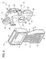
- FIG. 6is a perspective of a cradle of the mount system and the data collector exploded from the cradle;
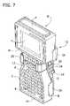
- FIG. 7is a perspective of the cradle supporting the data collector in the hold position
- FIG. 8is a perspective of a back of the cradle and data collector
- FIG. 9is an exploded perspective of the cradle showing a base, an actuator, arms, and a back cover of the cradle;
- FIG. 10is a perspective of a front of the base
- FIG. 11is a perspective of a back of the base
- FIG. 12Ais a perspective of one of the arms of the cradle showing an inner surface
- FIG. 12Bis a perspective of one of the arms showing an outer surface
- FIG. 13is a perspective of a front of the actuator
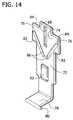
- FIG. 14is a perspective of a back of the actuator
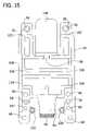
- FIG. 15is a an elevation of a front of the back cover
- FIG. 16is a perspective of a back of the back cover
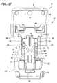
- FIG. 17is an elevation of the cradle holding the data collector with the back cover removed and the arms shown in phantom in the release position;
- FIG. 18is an elevation similar to FIG. 17 with the arms shown in phantom in the hold position;
- FIG. 19is a perspective of the back cover of the cradle partially slid into a male component of a coupler of the mount system
- FIG. 20is a perspective of the coupler and a clamp of the mount system
- FIG. 21is a perspective of the male component of the coupler
- FIG. 22is an exploded perspective of the male component with a portion of a shaft of the male component being broken away to show an internal ring;
- FIG. 23is a perspective of a female component showing an interior chamber
- FIG. 24Ais a perspective of a catch of the female component
- FIG. 24Bis a perspective of the catch sliding over a beveled edge of the male component with a portion of the male component being broken away;
- FIG. 24Cis a perspective similar to FIG. 24B except that the catch is engaged with a groove in the male component
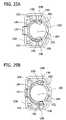
- FIG. 25Ais an elevation of a back end of the female component showing the catch with tabs projecting into the interior chamber;
- FIG. 25Bis an elevation similar to FIG. 25A but with the catch deformed causing the tabs to move substantially out of the interior chamber of the female component;
- FIG. 26Ais an elevation of the male and female components in an engaged position wherein relative rotation of the components is inhibited
- FIG. 26Bis a section taken along line 26 B- 26 B of FIG. 26A ;
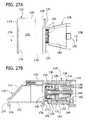
- FIG. 27Ais an elevation of the male and female components in an engaged position wherein relative rotation of the components is allowed
- FIG. 27Bis a section taken along line 27 B- 27 B of FIG. 27A ;
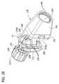
- FIG. 28is a perspective of the female component of the coupler attached to the clamp showing the interior chamber of the female component
- FIG. 29is a perspective of the female component of the coupler attached to the clamp.
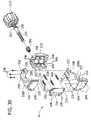
- FIG. 30is an exploded perspective of the clamp
- FIG. 31Ais a perspective of a jaw member of the clamp showing an engagement surface
- FIG. 31Bis a section taken along line 31 B- 31 B of FIG. 31A ;
- FIG. 32is a perspective of a threaded driver for the jaw member
- FIG. 33is an exploded perspective of the driver
- FIG. 34is a perspective of first and second clutch elements of the driver interlocked for conjoint rotation
- FIG. 35is a section taken along line 35 - 35 of FIG. 34 showing teeth of the first and second clutch elements drivingly engaged;
- FIG. 36is a perspective of the first and second clutch elements in a non-drive position in which the second clutch element rotates relative to the first clutch element;
- FIG. 37is a section taken along line 37 - 37 of FIG. 36 showing the teeth of the second clutch element passing over the teeth of the first clutch element.
- the mount system 10includes a cradle 12 (broadly, “holder”) for supporting an electrical device such as data collector D, a clamp 14 for securing the cradle to an object, and a coupler 16 connecting the cradle to the clamp (the numbers designating their subjects generally).
- the mount system 10is shown attached to a geomatics pole G ( FIG. 2 ) and a tripod T ( FIG. 3 ). Details of a suitable geomatics pole and a suitable tripod (broadly, “geomatics supports”) can be found in co-assigned U.S. Pat. Nos. 6,772,526 and 6,685,566, respectively, which are incorporated herein by reference in their entireties.
- “geomatics”is intended to encompass surveying and geographic positioning.
- the mount system 10can be attached to objects other than geomatics poles, tripods, or other geomatics equipment without departing from the scope of this invention.
- some embodiments (not shown) of the present inventioncan be mounted to the handlebars of a vehicle (e.g., an all terrain vehicle) or to the dashboard of a passenger vehicle (e.g., car, truck, van).
- the mounting system 10can be attached to the object using attachment devices other than the clamp 14 .
- the attachment devicecould be a flange having fastening holes for directly fastening the attachment device to the object.
- the attachment devicecould be a U-bolt.
- the illustrated data collector Dis a handheld computer available from Tripod Data Systems, Inc. of Corvallis, Oreg., U.S.A. under the product name RangerTM.
- the RangerTM data collectorhas a generally hourglass shape to facilitate holding of the data collector in one hand.
- the data collectorhas a plastic housing H with a front F, a back B, a bottom M, a top P and two opposed sides S.
- the front F of the data collector Dhas a display Y and a keypad K for entering data and commands.
- the top P of the data collector Dis equipped with standard ports (not shown) for connecting the data collector to geomatics equipment, a PC, or a notebook computer.
- the inventionis particularly useful with surveying and geographic positioning equipment, it is not limited to such applications.
- the inventionis envisioned as being useful to support handheld electrical devices having no relation to surveying or geographic positioning.
- the handheld electrical devicecan be one other than a data collector, such as a cellular phone, PDA or BlackberryTM, and can have configurations other than the one illustrated, such as rectangular or T-shaped.
- the present inventionalso has application to non-electrical devices.
- auxiliary devices” and “auxiliary components”include both electrical and non-electrical devices.
- the cradle 12is constructed to support the data collector D and comprises a base 18 for receiving the data collector and a pair of arms 20 disposed with respect to the base and to each other such that the arms are adjacent opposite sides of the data collector when the data collector is placed on the base.
- the cradle 12also includes an actuator 22 ( FIG. 9 ) for moving the arms 20 relative to the base 18 between a release position in which the arms are spaced apart a first distance L 1 allowing the data collector D to be freely removed from and placed on the base ( FIG. 5 ), and a hold position in which the arms are spaced apart a second distance L 2 smaller than the first distance for holding the data collector in the cradle ( FIGS. 4 and 7 ).
- the cradle 12further includes a back cover 24 for maintaining the actuator 22 and the arms 20 in relation with the base 18 .
- the back cover 24also constitutes a second connector element 26 , as will be explained hereinafter.
- the base 18 of the cradle 12has a longitudinal axis X, a transverse axis Z, a front 28 , and a back 30 .
- the front 28 of the base 18includes a peripheral retainer projecting outwardly from the base for supporting the bottom M and sides S of the data collector D to restrain the data collector from lateral movement with respect to the base.
- the illustrated retaineris discontinuous and comprises a bottom flange 32 and two pair of opposing side flanges 34 , 36 .
- One pair of side flanges 34are generally adjacent the bottom flange 32 and extend generally parallel to the longitudinal axis X of the base 18 .
- the other pair of side flanges 36are positioned adjacent the top of the base 18 and have generally L-shape configurations. It is understood that the flanges can be continuous or have other arrangements. For example, the bottom flange and the side flanges adjacent thereto could be formed as a single piece.
- the front 28 of the base 18also includes an engagement surface adapted to engage the back of the data collector D when the data collector is placed in the cradle.
- the engagement surfacecomprises four, spaced apart raised portions 38 .
- Each of the raised portions 38is proximate to one of the side flanges 34 , 36 .
- the raised portions 38 proximate the straight side flanges 34each have a generally rectangular shape whereas the raised portions adjacent the L-shaped side flanges 36 are also generally L-shaped.
- the raised portions 38provide spacing between the majority of the front 28 of the base 18 and the data collector D, which facilitates removal of the data collector from the cradle 12 or placement of the data collector on the cradle.
- the back 30 of the base 18 as shown in FIG. 11has a pair of upper standoffs 40 and a pair of lower standoffs 42 .
- the upper standoffs 40are positioned adjacent the top of the base 18 and have fastener holes 44 therein for receiving fasteners 46 ( FIG. 9 ), such as screws, for securing the back cover 24 to the base.
- fasteners 46FIG. 9
- surrounding each fastener hole 44 in the upper standoffsis an annular recess portion 48 (like a counterbore) for aligning with and receiving a first pair of alignment tabs 50 located on the back cover ( FIG. 15 ).
- the lower standoffs 42are located adjacent opposite sides of the base 18 at approximately the longitudinal center of the base.
- the lower standoffs 42are elongate and have four apertures therein. Two of the apertures (i.e., the upper aperture 52 and the lower aperture 54 ) on each of the lower standoffs 42 are for receiving fasteners 46 (e.g., screws) for securing the back cover 24 to the base. Another one of the apertures 56 in the lower standoffs 42 is for receiving one of a second pair of alignment tabs 58 positioned on the back cover 24 for aligning the back cover with the base 18 ( FIG. 15 ). The final aperture 60 is just for material reduction purposes.
- each of the arms 20has an inner surface 62 , an outer surface 64 , a finger 66 extending outwardly from one end of the arm and a slide portion 68 at the opposite end of the arm.
- the arms 20are mirror images of each other and therefore only one of the arms will be described.
- the arm 20is contoured to match the shape and size of the respective side S of the data collector D to which it is designed to engage.
- the slide portion 68has a protuberance 70 , 72 located on each of the inner and outer surfaces 62 , 64 .
- the protuberance 70 located on the inner surface 62is adapted to slidingly engage the actuator 22
- the protuberance 72 located on the outer surface 64is adapted to slidingly engage back cover 24 .
- the protuberance 72 on the outer surface 64extends parallel to a longitudinal plane of the finger 66 ( FIG. 12B ).
- the protuberance 70 on the inner surface 62is disposed at an angle with respect to a longitudinal plane of the finger ( FIG. 12A ).
- the protuberances 70 , 72 and their interactions with actuator 22 and back cover 24are described in further detail below.
- the arms 20 of the cradle 12are shaped and arranged so that in the release position neither of the fingers 66 is located in opposed relation with the front F or back B of the data collector D ( FIG. 5 ), and in the hold position the fingers 66 are disposed in a position opposite to the front of the data collector ( FIG. 4 ).
- the fingers 66each project toward the finger of the opposite arm 20 and are adapted to extend over and engage the front of the data collector D when the cradle 12 is in its hold position to firmly hold the data collector in the cradle.
- the data collector Dwhen properly placed in the cradle 12 , can be supported by the cradle at any position including upside down without the data collector falling from the cradle.
- the location of a geomatics support with the cradle 12 mounted theretocan be changed with the data collector D placed in the cradle without the data collector falling from the cradle and being damaged.
- the arms 20may release hold of the data collector D so that it can be removed and replaced from the cradle 12 without disturbing the geomatics support.
- the actuator 22 of the cradle 12comprises a generally cruciform plate 74 adapted to move longitudinally with respect to the base 18 to move the arms 20 between the hold and release positions.
- the cruciform plate 74has ears 76 projecting laterally from opposite sides of the plate. The portion of the plate 74 above the opposing ears 76 is slightly narrower than the portion of the plate below the ears.
- the actuator 22further comprises a handle 78 attached to the plate 74 for facilitating moving the plate.
- the handle 78is formed as a one-piece unit with the plate 74 and extends outwardly from the plate to a position where the handle can be easily gripped. A free end of the handle 78 is formed with a lip 80 to increase the ability of the handle to be gripped.
- the front of the plate 74is adapted for being placed in face-to-face relation with the back 30 of the base 18 such that the portion of the plate below the ears 76 is disposed between the pair of lower standoffs 42 (see, FIG. 17 ).
- the front of the plate 74 and the back 30 of the base 18have generally flat, smooth engaging surfaces for allowing the plate to slide along the longitudinal axis X of the base from an extended position and a retracted position. In the extended position, a lower lateral edge 82 of each of the plate ears 76 contacts and is stopped by the pair of lower standoffs 42 on the base 18 (see, FIG. 18 ). Positioning the plate 74 in its extended position moves the arms 20 to their release position as explained in greater detail below.
- each of the plate ears 76contacts and is stopped by the pair of upper standoffs 40 on the base 18 .
- the portion of the plate 74 above the ears 76is disposed between the upper standoffs 40 in this position.
- the portion of the plate 74 below the ears 76remains between the pair of lower standoffs 42 .
- the lower standoffs 42also provide a longitudinal guide for moving the plate 74 between its retracted and extended positions. Positioning the plate 74 in its retracted position, moves the arms 20 to their hold position, as is also explained in greater detail below.
- the back of the plate 74 as shown in FIG. 14has three channels therein. Two of the channels 86 are sized and shaped for receiving the protuberances 70 on the inner surfaces 62 of the arms 20 ( FIG. 12A ). The channels 86 are angled with respect to a longitudinal plane of the plate such that as the plate 74 is moved longitudinally with respect to the base 18 between its extended and retracted positions, the protuberances 70 of the arms 20 slide in the channels causing the arms to move laterally with respect to the base between their hold and release positions ( FIG. 14 ).
- the third channel 88is positioned near the top edge of the plate 74 and is adapted for receiving a projection 90 positioned on the back cover 24 ( FIG. 15 ).
- the third channel 88 in the back of the plate 74 and the projection 90 on the back cover 24provide an alignment guide for the plate as the plate is move between the extended and retracted positions.
- the projection 90 in combination with the back cover 24secure the actuator 22 to the base 18 .
- a wedge 92 on the back of the plate 74cooperates with a resilient lower clasp 94 on the back cover 24 to releasably hold the plate in both the extended and retracted positions corresponding to the release position and hold position, respectively, of the arms 20 .
- the clasp 94slides up an inclined top surface of the wedge 92 until a lip 96 on the clasp extends past the surface of the wedge.
- the clasp 94snaps downward such that the lip 96 extends below the top surface of the wedge 92 thereby holding the plate 74 in the retracted position.
- the plate 74To move the plate 74 from the retracted position to extended position, the plate is pulled (slid axially downward) with sufficient force to cause the clasp 94 to deflect upward thereby releasing the lip 96 from the wedge 92 .
- the plate 74can be moved until the lip 96 passes off of the top surface of the wedge 92 and is positioned on the opposite side of the wedge thereby to hold the plate in the extended position.
- the back cover 24 of the cradle 12which maintains the actuator 22 and the arms 20 in relation with the base 18 of the cradle, is shown.
- the back cover 24is fastened to the back 30 of the base 18 using fasteners 46 ( FIG. 9 ).
- the back cover 24has six countersunk fastening holes 98 for receiving fasteners 46 ( FIG. 16 ). Two of the fastening holes 98 align with the fastening holes 44 in the upper standoffs 40 of the base 18 and the other four fastening holes 98 align with the fastening holes 52 , 54 in the lower standoffs 42 of the base (see FIGS. 11 and 15 ).
- the back cover 24also has six alignment tabs for aligning the back cover with the base 18 .
- first and second pairs of alignment tabs 50 , 58align with and engage the upper and lower standoffs 40 , 42 of the base 18 , respectively.
- a third pair of alignment tabs 100align with and engage interior sides of the lower standoffs 42 of the base 18 .
- the third pair of alignment tabs 100not only align the base 18 and the back cover 24 but also provide a guide to the plate 74 of the actuator 22 to inhibit the actuator from tilting away from the base and to thereby maintain the plate in face-to-face relationship with the back 30 of the base.
- the back cover 24also has two alignment portions 102 , 104 for aligning with the upper and lower standoffs 40 , 42 on the base 18 , respectively.
- the tabs 50 , 58 and standoffs 40 , 42operate to form a space between the base 18 and the back cover 24 in which portions of the arms 20 and actuator 22 are slidably received.
- the back cover 24also includes a laterally extending groove 106 ( FIG. 15 ) for receiving the protuberances 72 on the outer surfaces 64 of the arms 20 ( FIG. 12B ).
- the groove 106 and projections 72cooperate to mount the arms 20 on the cradle 12 and inhibit movement of the arms longitudinally with respect to the actuator 22 as the arms are moved between their hold and release positions.
- the protuberances 70 on the inner surface 70 of the arms 20slid within the angled channels 86 in the plate 74 of the actuator thereby moving the arms laterally away from or toward the longitudinal axis X of the base 18 ( FIGS. 17 and 18 ).
- the protuberances 72 on the outer surface 64 of the arms 20slide with the groove 106 in the back cover 24 which maintains the longitudinal position of the arms with respect to the base 18 .
- the back cover 24also includes shoulders 108 extending longitudinally along the peripheral edges of the back cover.
- the back cover 24has an upper clasp 110 with a lip 112 capable of resilient deflection similar to the lower clasp 94 described above.
- movement of the actuator 22 of the cradle 12causes the arms 20 to move in a direction generally orthogonal to the movement of the actuator thereby to move the arms between the release and hold positions ( FIGS. 17 and 18 ). Since the actuator 22 is movable linearly along the longitudinal axis X of the base 18 , the arms 20 move in directions that are transverse to the base. As a result, pushing the actuator 22 upward with respect to the longitudinal axis X of the base 18 causes the arms 20 move closer together ( FIG. 18 ) and pulling the actuator downward with respect to the longitudinal axis of the base causes the arms to move apart ( FIG. 17 ).
- the actuator 22is easy to use, the data collector D can be placed on or removed from the cradle 12 while the cradle is mounted to a geomatics pole G or tripod T without compromising the positioning of the pole or tripod. Moreover, the actuator 22 can be moved between its extended and retracted positions using only one hand.
- the coupler 16which attaches the cradle 12 to the clamp 14 , comprises a male component, indicated at 116 , and a female component, indicated at 118 .
- the male component 116 as shown in FIGS. 19 and 20includes a shallow channel 120 (broadly, “a first connector element”) and a housing 122 formed on one side of the channel.
- a cylindrical stem 124 having first and second ends 126 , 128extends outwardly from the housing 122 ( FIG. 21 ).
- the first end 126 of the stem 124is connected to the housing 122 and has a plurality of detents 130 in spaced relation positioned around the circumference of the stem.
- a passage 132extends through the stem 124 from the first end 126 to the second end 128 ( FIG. 22 ).
- the passage 132is divided by an interior ring 134 into an inward portion 136 and an outward portion 138 (see, FIG. 26B ).
- the stem 124 illustrated in FIG. 22is partially broken away to show the interior ring 134 .
- a plug 140includes a cylinder 142 having a closed end 144 , an open end 146 , and a post 148 affixed to the closed end.
- the post 148 of the plug 140extends out of the cylinder 142 and has a free end with a centrally positioned fastener hole 152 .
- the plug 140is positioned in the inward portion 136 of the passage 132 .
- a spring 154is received in the cylinder 142 around the post 148 and engages the interior ring 134 to bias the plug in a direction away from the interior ring.
- a double walled sleeve 156 having a peripheral rim 158 at one endis adapted for being received in the outward portion 138 of the passage 132 .
- the sleeve 156has a passageway 160 and a countersink 162 for receiving a fastener 164 for connecting the sleeve to the post 148 so that the plug 140 and sleeve move conjointly.
- the fastener 164extends through the sleeve 156 , the interior ring 134 in the stem passage 132 , and into the fastening hole 152 in the post 148 .
- a head 166 of the fastener 166 and a washer 168are fully received in the countersink 162 .
- the rim 158 of the sleeve 156is axially spaced from the second end 128 of the stem 124 such that an annular groove 170 is formed by the sleeve 156 and the stem 124 .
- the portions of the male component 116 extending outwardly from the housing 122are collectively referred to herein as a shaft.
- the channel 120 (or first connector element) of the male component 116has a web 172 and first and second side walls 174 at opposite sides of the web. As shown in FIG. 21 , the first and second side walls 174 each have an in-turned lip 176 at its free edge extending generally toward the other sidewall and lip, and generally parallel to the web 142 .
- the back cover 24 (second connector element) of the cradle 12 and the channel 120 (first connector element) of the coupler 16collectively form a connector in the illustrated embodiment. As shown in FIG. 20 , the channel 120 further including open ends 178 .
- the channel 120is shaped and arranged so that the shoulders 108 of the back cover 24 may be inserted into the channel through either open end 178 of the channel (see, FIG. 19 ).
- the upper clasp 110 of the back cover 24is adapted to snap over an edge of the channel 120 and thereby secure the male coupler 116 to the cradle 12 no matter which way the back cover 24 is inserted into the channel 120 .
- the cradlecan be positioned on either side of the surveying equipment to facilitate use of the geomatics support and data collector D by either a left-handed ( FIG. 2 ) or right-handed user ( FIG. 3 ).
- the cradle 12can support the data collector D in an upright, forward facing position no matter which way it extends from the geomatics support.
- a thumb tab 180 on the upper clasp 110 of the back coverallows the lip 112 to be moved to a position free of engagement with the channel 120 ( FIG. 16 ).
- the back cover 24can be slid out of the male component 116 .
- the female component 118includes a generally tapered body 182 defining an interior chamber 184 sized and shaped for receiving the shaft of the male component 116 , including the stem 124 and sleeve 156 .
- a catch 186 including two tabs 188extends into the interior chamber 184 of the female component 118 for cooperating with the groove 170 on the male component 116 to secure the male component with respect to the female component.
- the catch 186is generally wishbone shaped, comprising two legs 190 and a button 192 located at the apex of the legs.
- the tabs 188are located near free ends of the legs 190 .
- the legs 190 , button 192 and tabs 188are formed as one piece of flexible, resilient material ( FIG. 24A ).
- the button 192extends through a hole 194 in the body 182 of the female component 118 and can be depressed to selectively release the tabs 188 from the groove 170 on the male component 116 to thereby allow the male component to be removed from the female component.
- Two slides 196(broadly, “a release”) that slope downward and away from the interior chamber 184 of the body 182 of the female component 118 are formed in the body of the female component so that they engage the tabs 188 of the catch 186 ( FIGS. 25A and 25B ).
- depression of the button 192causes the tabs 188 to move along the slides 196 away from the interior chamber 184 to a position free of engagement with the groove 170 in the male component 116 .
- the catch 186is resiliently deformed in this action and therefore biased to a shape in which the tabs 188 project into the interior chamber 184 and engage the groove 170 in the male component 116 .
- the male component 116is adapted for insertion into the interior chamber 184 of the female component 118 past the catch 186 so that the tabs 188 of the catch are received in the groove 170 .
- the sleeve 156 of the male component 116has a beveled edge 125 adapted to engage the catch 186 during insertion of the male component into the interior chamber 184 of the female component 118 and deform the catch (i.e., spread the tabs 188 apart) to permit the male component to pass the catch when being pushed into the interior chamber (see FIG. 24B ).
- the peripheral rim 158 of the sleeve 156is arranged generally parallel to the tabs 188 of the catch 186 for preventing movement of the male component 116 past the catch in a direction out of the interior chamber 184 .
- the tabs 188 of the catch 186are received in the groove 170 and secure the male component 116 against axial movement (see FIG. 24 ).
- the female component 118also includes detents 198 located adjacent an entrance to the interior chamber 184 ( FIG. 23 ) so that when the male component 116 is engaged with the female component, the detents 130 , 198 intermesh and prevent rotation of the male component 116 with respect to the female component about the axis of the stem 124 ( FIGS. 26A and 26B ).
- the male component 116can be moved axially outward from the interior chamber 184 of the female component so that the detents 130 positioned on the male component 116 are substantially free of the detents 198 on the female component 118 thereby to allow the male component to be rotated with respect to the female component ( FIGS. 27A and 27B ). This can occur without releasing the connection of the male and female components 116 , 118 .
- the male component 116By pulling axially outward on the cradle 12 , the male component 116 , including specifically the stem 124 and housing 122 , moves outwardly from the interior chamber 184 of the female component 118 .
- the sleeve 156is held in place against such axial movement by engagement of the rim 158 with the tabs 188 of the catch 186 .
- the remainder of the male component 116(including specifically stem 124 ) moves axially relative to the sleeve 156 and plug 140 , permitting the detents 130 , 198 to disengage.
- the coupler 16has a first position wherein the cradle 12 attached to the male component 116 is spaced a first distance from the female component 118 and is fixed rotationally relative to the female component ( FIGS. 26A and 26B ), and a second position wherein the cradle is spaced a second distance greater than the first distance from the female component and is free to rotate with respect to the female component ( FIGS. 27A and 27B ).
- the cradle 12 supporting the data collector Dcan be easily rotated to a desired angle using one hand and without disconnecting it from the clamp 14 .
- the body 182 of the female component 118also includes a back end 200 .
- the back end 200has four fastening holes 202 for receiving fasteners 204 ( FIG. 30 ) for attaching the female component 118 to the clamp 14 .
- FIG. 28illustrates the female component 118 attached to the clamp 14 .
- the clamp 14comprises a rigid clamp body 208 , an anvil 210 , a moveable jaw member 212 , and a driver 214 for moving the moveable jaw member in relation to the anvil.
- the clamp body 208is formed by two body elements 208 A, 208 B that are connected together.
- the first body element 208 Ahas a plurality of spaced protrusions 216 for insertion into one of a plurality of spaced sockets (not shown) formed in the second body element 208 B.
- the clamp body 208defines a channel 218 for receiving the moveable jaw member 212 and for allowing the moveable jaw member to move with respect to the channel.
- An end wall 220 of the clamp body 208has an exterior raised portion 226 for insertion into the female component 118 of the coupler 16 .
- the end wall 220has an interior recessed portion 227 for receiving the anvil 210 of the clamp 14 and an edge 229 surrounding the recessed portion.
- the wall 220also has four fastener holes 226 for allowing the anvil 210 and the clamp body 208 to be fastened to the female component 118 of the coupler 16 .
- the wall 220also has another, larger hole 228 for receiving and maintaining the alignment of a screw 230 of the driver 214 .
- a screw receiving portion 232 of the clamp body 208has a passageway (not shown) through it for receiving the screw 230 .
- Three fastener apertures 236are located in the screw receiving portion 232 for receiving fasteners 238 for securing the clamp body 208 elements together.
- the anvil 210has four fastener holes 240 and a curved, but generally wedge-shaped elastomeric pad 242 .
- the four fastener holes 240are positioned for allowing fasteners 204 (e.g., screws) to pass through the fastener holes 226 in the end wall 220 and into the fastener holes 202 in the female component 118 of the coupler 16 to secure the anvil 210 , clamp body 208 , and female component 118 together.
- the anvil 210also includes a semicircular recess 244 for allowing the screw 230 of the driver 214 to pass through the anvil and into the female component 118 .
- the elastomeric pad 242extends outwardly beyond the edge 229 of the clamp body 208 .
- the elastomeric pad 242 of the anvil 210 and the edge of the clamp body 208cooperate to define a second jaw member for securing the support in the clamp 14 .
- the second jaw memberis sized and shaped for general conformance to a surface of the geomatics pole G or tripod T.
- the pad 242increases the frictional engagement of the anvil 210 with the geomatics support to inhibit the clamp 14 from movement with respect to the support.
- the jaw member 212(or “first jaw member”) is moveable relative to the anvil 210 between a secured positioned wherein the jaw and second jaw members are secured to the geomatics support and an unsecured positioned wherein the clamp 14 can be moved relative to the geomatics support.
- the first and second jaw memberscooperate to define a jaw for securing the clamp 14 to the support.
- the jaw member 212includes an engagement surface sized and shaped for general conformance to a surface of the geomatics support (in this case, a geomatics pole G).
- the engagement surfaceincludes a rigid pole engagement surface 246 and an elastomeric pad 248 for engaging the geomatics pole G in the secured position of the clamp 14 .
- the elastomeric pad 248has two pad segments 248 A, 248 B.
- the elastomeric pad segments 248 A, 248 Bhave curved surfaces for conformally engaging the pole G while the rigid pole engaging surface 246 has a generally rounded surface for engaging in the pole.
- the elastomeric pad 248projects above the rigid surface 246 such that when the jaw member 212 is brought into contact with the geomatics pole G (or tripod T) the elastomeric pad 248 contacts the geomatics pole and the pole is substantially free of contact with the rigid surface 246 .
- the elastomeric pad 248is compressed such that both the elastomeric pad and rigid surface 246 contact the geomatics pole.
- the clamp 14grips the pole G more tightly at a relatively low compression.
- the jaw member 212is sized and shaped for being received in the channel 218 of the clamp body 208 . More particularly, the jaw member 212 has shoulder members 250 and an arcuate surface 252 for being received in the channel 218 of the clamp body. Thus, the jaw member 212 is adapted to slide with respect to the clamp body 208 , guided by the channel 218 . In addition, the jaw member 212 has an opening 254 with an insert 256 positioned in the opening. The insert 256 has interior threads receiving the screw 230 of the drive 214 and causing movement of the drive to be transferred to the jaw member 212 to thereby move the jaw member linearly with respect to the clamp body 208 .
- the jaw member 212also has four holes 258 extending therethrough for allowing a screw driver (not shown) to be inserted through the holes for accessing the fasteners 204 securing the anvil 210 and wall 220 of the clamp body 208 to the female component 118 .
- a bushing 260is mounted on the screw 230 for use in inhibiting axial movement of the screw relative to the clamp body 208 and anvil 210 .
- the bushing 260 and a washer 262are positioned on the screw 230 adjacent the screw receiving portion 232 of the clamp body 208 ( FIG. 30 ).
- the driver 214includes a hand grip 264 and the screw 230 threadably connected to the jaw member 212 . Rotation of the hand grip 264 causes the jaw member 212 to move along the screw 230 between the secured and unsecured positions.
- the driver 214further comprises a torque limiter to inhibit overtightening of the jaw member 212 against the geomatics support and thereby prevent damage to the geomatics support.
- the torque limitercomprises a clutch interconnecting the hand grip 264 and the screw 230 that is adapted to permit relative rotation of the hand grip and screw upon encountering resistance in only one direction (i.e., clockwise) corresponding to moving the jaw member 212 toward the secured position.
- the clutchhas a first clutch element 266 fixed to the screw 230 and a second clutch element 268 mounting the hand grip 264 and supported by the first clutch element for axial translation relative to the first clutch element between a drive position in which the first and second clutch elements are interlocked for conjoint rotation ( FIGS. 34 and 35 ) and a non-drive position in which the second clutch element rotates relative to the first clutch element ( FIGS. 36 and 37 ).
- the first and second clutch elements 266 , 268are formed with inclined teeth 270 , 272 that drivingly engage each other in the drive position and disengage each other in the non-drive position.
- the teeth 270 , 272are generally sawtooth shaped to provide greater resistence to relative rotation of the first and second clutch elements 266 , 268 in a first direction (i.e. counterclockwise) than in a second, opposite direction (i.e., clockwise).
- the first clutch element 266 of the driverincludes a head 274 having flanged ends 276 fixed to the screw 230 for conjoint rotation therewith.
- the first clutch element 266also includes a threaded insert 296 (broadly, “a connector”) for connecting the first clutch element to the screw 230 .
- the second clutch element 268includes a sleeve 278 with a free end 280 and a flanged end 282 .
- the grip 264that bears against the sleeve 278 and head 274 for rotation of the screw 230 up to a threshold torque.
- the flanged end 282 of the sleeve 278 and one of the flanged ends 276 of the head 274have the inclined teeth 270 , 272 that drivingly engage each other.
- the hand grip 264is resiliently deformable so that upon reaching the threshold torque the grip is deformed thereby allowing the sleeve 276 to axially move with respect to the head 274 (see, FIG. 36 ).
- the deformed handgrip 264is shown in phantom in FIG. 36 .
- the teeth 272 of the flanged end 282 of the sleeve 278pass over the teeth 270 of the flanged end 276 of the head 274 ( FIGS. 36 and 37 ), which allows the grip 264 and sleeve 278 to rotate relative to the head and screw.
- the threshold torqueis directly proportional to the resiliency of the grip 264 .
- the grip 264has an outer cylindrical wall 284 and an inner cylindrical wall 286 defining a passage 288 through the grip.
- the outer cylinder wall 284is undulating to form an easy-to-grip surface.
- the grip 264also has two sides 290 (i.e, ends) extending between the outer and inner walls 284 , 286 .
- Each side 290has a recess 292 adjacent the inner wall 286 that is sized and shaped for receiving the flange end 276 of the sleeve 278 in one of the recesses, and a washer 294 in the other recess.
- the washer 294has an inner diameter greater than the outer diameter of the sleeve 278 so that the free end 280 of the sleeve can pass through the inner diameter of the washer when the sleeve is moved axially.
- a cap 298fits over the washer 294 and is received in the recess 292 with the washer.
- a portion of an objectsuch as a geomatics support, is placed in the clamp body 208 of the clamp 14 such that the first and second jaw members are disposed on opposite sides of the support.
- the hand grip 264 of the driver 214is rotated in a clockwise direction to move the jaw member 212 via the screw 230 from an unsecured position to a secured position wherein the support is secured between the jaw members.
- the wedge-shaped elastomeric pad 242 of the anvil 210 and the edge 229 of the clamp body 208are generally sized and shaped to conform to the surface of the support as the first jaw member 212 moves the support against the second jaw member.
- the elastomeric pad 242is compressed so that the rigid edge 229 of the clamp body 208 contacts the support.
- the elastomeric pad segments 248 A, 248 B of the jaw member 212contact the support while the rigid surface 246 of the jaw member is substantially free of contact with the support.
- the elastomeric pad 248is compressed such that both the elastomeric pad and rigid surface 246 contact the support to securely mount the clamp on the support.
- the stress applied to the support by the clamp 14is applied over a large surface area of the support.
- the torque limiter of the driver 214inhibits overtightening of the jaw member 212 against the support and thereby prevents damage to the geomatics support.
- rotation of the hand grip 264causes rotation of the first and second clutch element 266 , 268 of the torque limiter and the screw 230 to thereby move the jaw member 212 .
- the handgrip side 290is undeformed (as shown in phantom in FIG. 34 ) and inclined teeth 270 , 272 of the first and second clutch elements 266 , 268 drivingly engage each other ( FIG. 35 ).
- the biasing force applied by the hand grip 264 against the flanged end 282 of the sleeve 278keeps the teeth 272 from riding up the incline of teeth 270 .
- the sides 290 of the hand grip 264resiliently deform (as indicated by the arrows shown in FIG. 36 ) so that teeth 272 of the second clutch element 268 ride up and pass over the teeth 270 of the first clutch element 266 thereby causing the sleeve 276 to move axially with respect to the head 274 ( FIGS. 36 and 37 ).
- the grip 264 and sleeve 278rotate relative to the head and screw to inhibit further tightening of the jaw member 212 against the support.
- a hand gripcould be used in other configurations to limit the torque that can be applied.
- the hand grip 264is rotated in a counterclockwise direction to move the jaw member away from the anvil 210 and the support.
- the teeth 270 , 272 of the first and second clutch elements 266 , 268remain drivingly engaged with each other when the hand grip 264 is rotated counterclockwise because the engaging surfaces of the teeth are perpendicular to the direction of rotation.
- the torque limiteronly works when tightening the clamp 14 (i.e., when the hand grip 264 is rotated in a clockwise direction).
- the various components of the mount system 10excluding the insert 256 , bushing 260 , and screw 230 , are molded from plastic. It is understood however that the components can be formed from other materials without departing from the scope of this invention.
Landscapes
- Engineering & Computer Science (AREA)
- General Engineering & Computer Science (AREA)
- Mechanical Engineering (AREA)
- Physics & Mathematics (AREA)
- General Physics & Mathematics (AREA)
- Radar, Positioning & Navigation (AREA)
- Remote Sensing (AREA)
- Clamps And Clips (AREA)
Abstract
Description
Claims (7)
Priority Applications (1)
| Application Number | Priority Date | Filing Date | Title |
|---|---|---|---|
| US11/107,441US7669816B2 (en) | 2005-04-15 | 2005-04-15 | Clamp for mount system |
Applications Claiming Priority (1)
| Application Number | Priority Date | Filing Date | Title |
|---|---|---|---|
| US11/107,441US7669816B2 (en) | 2005-04-15 | 2005-04-15 | Clamp for mount system |
Publications (2)
| Publication Number | Publication Date |
|---|---|
| US20060231714A1 US20060231714A1 (en) | 2006-10-19 |
| US7669816B2true US7669816B2 (en) | 2010-03-02 |
Family
ID=37107599
Family Applications (1)
| Application Number | Title | Priority Date | Filing Date |
|---|---|---|---|
| US11/107,441Active2028-02-11US7669816B2 (en) | 2005-04-15 | 2005-04-15 | Clamp for mount system |
Country Status (1)
| Country | Link |
|---|---|
| US (1) | US7669816B2 (en) |
Cited By (33)
| Publication number | Priority date | Publication date | Assignee | Title |
|---|---|---|---|---|
| US20090173863A1 (en)* | 2006-07-21 | 2009-07-09 | Peter Crown | Method and apparatus for securing a device at a desired location |
| US20100066217A1 (en)* | 2008-09-12 | 2010-03-18 | Funai Electric Co., Ltd. | Cabinet for electronic device |
| US20110183728A1 (en)* | 2010-01-22 | 2011-07-28 | Cheng Uei Precision Industry Co., Ltd. | Mobile Phone Holder |
| US20120061414A1 (en)* | 2010-09-10 | 2012-03-15 | Bundy Richard V | Tape Gun Holder Device |
| US20120266735A1 (en)* | 2011-04-20 | 2012-10-25 | Jim Dunlop | Adjustable item holder |
| US20130068908A1 (en)* | 2011-09-15 | 2013-03-21 | Henryk Bury | Retaining Device |
| US8469325B2 (en)* | 2011-10-26 | 2013-06-25 | Tsung-Yao Yu | Musical instrument stand with an angle adjustment function |
| US20140007408A1 (en)* | 2012-07-03 | 2014-01-09 | Volcano Corporation | PIM Holder With Clamping Device |
| US20140103181A1 (en)* | 2012-10-14 | 2014-04-17 | Sd & Kephart Llc | Universal mounting system |
| WO2015186131A1 (en)* | 2014-06-05 | 2015-12-10 | Ben Yehuda Iftach | Self-photographing mount device |
| US9486897B2 (en) | 2013-03-14 | 2016-11-08 | Kevin Trotsky | Foldable clamp for a mounting system |
| US20160355205A1 (en)* | 2015-07-20 | 2016-12-08 | Cheryl Glynn Upton | Device Holding Clip for Shopping Cart |
| USD777548S1 (en) | 2014-10-06 | 2017-01-31 | Octa Llc | Clamp |
| CN106641610A (en)* | 2016-11-04 | 2017-05-10 | 深圳电航空技术有限公司 | Holder bracket |
| US20170284433A1 (en)* | 2016-03-31 | 2017-10-05 | John Curtis Thomas | Mounting assembly |
| US20180001950A1 (en)* | 2016-07-01 | 2018-01-04 | Jeffrey M. Allen | Handlebar accessory mount |
| US10101770B2 (en) | 2016-07-29 | 2018-10-16 | Mobile Tech, Inc. | Docking system for portable computing device in an enclosure |
| US20180295975A1 (en)* | 2017-04-18 | 2018-10-18 | Robert Washington | Portable holder for an electronic device |
| US10198036B2 (en) | 2012-12-05 | 2019-02-05 | Mobile Tech, Inc. | Docking station for tablet device |
| US10251144B2 (en) | 2015-12-03 | 2019-04-02 | Mobile Tech, Inc. | Location tracking of products and product display assemblies in a wirelessly connected environment |
| US20190195252A1 (en)* | 2017-12-27 | 2019-06-27 | Pryor Products, Inc. | Compact support clamp |
| US10517056B2 (en) | 2015-12-03 | 2019-12-24 | Mobile Tech, Inc. | Electronically connected environment |
| US10593443B1 (en) | 2019-01-24 | 2020-03-17 | Mobile Tech, Inc. | Motion sensing cable for intelligent charging of devices |
| US10728868B2 (en) | 2015-12-03 | 2020-07-28 | Mobile Tech, Inc. | Remote monitoring and control over wireless nodes in a wirelessly connected environment |
| US11109335B2 (en) | 2015-12-03 | 2021-08-31 | Mobile Tech, Inc. | Wirelessly connected hybrid environment of different types of wireless nodes |
| US11287258B2 (en) | 2019-01-16 | 2022-03-29 | Milwaukee Electric Tool Corporation | Laser projection tools and mounting accessories |
| USD950475S1 (en) | 2020-03-30 | 2022-05-03 | Marklyn Group, Inc. | Adjustable vehicular holder for an electronic or air freshener device |
| US11385055B2 (en) | 2019-07-23 | 2022-07-12 | Milwaukee Electric Tool Corporation | Laser emitter with a modular storage unit |
| US11540350B2 (en) | 2018-10-25 | 2022-12-27 | Mobile Tech, Inc. | Proxy nodes for expanding the functionality of nodes in a wirelessly connected environment |
| US20230013328A1 (en)* | 2021-07-08 | 2023-01-19 | Octopus Adventure Company LLC | Quick-release interconnect |
| US20230033519A1 (en)* | 2021-07-30 | 2023-02-02 | Milwaukee Electric Tool Corporation | Laser Level Mounting Device |
| US20230096795A1 (en)* | 2020-02-28 | 2023-03-30 | Technologies Cgc Inc. | Coupling systems for releasably coupling equipment to a patient transport systems |
| US11971255B2 (en) | 2020-11-02 | 2024-04-30 | Milwaukee Electric Tool Corporation | Laser level alignment tool |
Families Citing this family (25)
| Publication number | Priority date | Publication date | Assignee | Title |
|---|---|---|---|---|
| DE102007032579B4 (en)* | 2007-07-09 | 2017-05-04 | Tyco Electronics Services Gmbh | End closure for telecommunications and data technology |
| DE102007032578A1 (en)* | 2007-07-09 | 2009-01-15 | Adc Gmbh | Connection module for telecommunication and data technology |
| US7650846B2 (en)* | 2007-08-31 | 2010-01-26 | Mckim Michael | Mainsail reefing system |
| USD579360S1 (en) | 2007-12-28 | 2008-10-28 | Crain Enterprises, Inc. | Elongated level vial support for a pole |
| US7707733B1 (en) | 2007-12-28 | 2010-05-04 | Seco Manufacturing Company, Inc. | Level vial support for a geomatics pole |
| DE102008011159A1 (en)* | 2008-02-26 | 2009-08-27 | Adc Gmbh | Carrier system for receiving components of telecommunications and data technology |
| DE102008029802B3 (en)* | 2008-06-24 | 2009-12-31 | Adc Gmbh | Fuse module for a fiber optic connection module |
| US8695957B2 (en)* | 2009-10-30 | 2014-04-15 | Pryor Products | Compact support clamp with rotating equipment attachment and jaw operator |
| US8376292B2 (en)* | 2010-01-02 | 2013-02-19 | Mike Cicco | Personal electronic device holder |
| CN103123034A (en)* | 2011-11-18 | 2013-05-29 | 蔡文峰 | Clamping device for electronic articles |
| US9335125B2 (en) | 2012-06-26 | 2016-05-10 | Selso Tello | Universal firearm marksmanship system |
| FR3020928A1 (en)* | 2014-05-13 | 2015-11-20 | Atelier Haute Comm Sas | SYSTEM FOR ATTACHING A MOBILE COMMUNICATION DEVICE TO A PROTECTIVE MEDIUM AND METHOD FOR IMPLEMENTING IT |
| US10405658B2 (en)* | 2014-11-07 | 2019-09-10 | Mark McCrate | Auxiliary bracket for electronic display |
| US10739109B1 (en) | 2016-10-28 | 2020-08-11 | Selso Tello | Firearm marksmanship system with chamber insert |
| US10288987B2 (en)* | 2016-12-09 | 2019-05-14 | Moises H Olmos-Calderon | Tripod accessory clamp |
| USD874911S1 (en)* | 2017-07-05 | 2020-02-11 | Ergonomic Solutions International Limited | Fitting |
| DE202019102923U1 (en)* | 2019-05-23 | 2020-08-25 | Ga Actuation Systems Gmbh | Clamping device for bars |
| US11218580B2 (en)* | 2019-10-01 | 2022-01-04 | BioRhythmic Gear LLC | Multi-positioning communication device holding system |
| CN110836308B (en)* | 2019-11-26 | 2021-08-27 | 江苏米孚自动化科技有限公司 | Multifunctional base for electromechanical equipment installation |
| US20210361519A1 (en)* | 2020-05-22 | 2021-11-25 | Doug Hagy | Mounting Bracket for a Massage Gun |
| CN112263117B (en)* | 2020-10-23 | 2021-09-21 | 南京梵鼎信息技术有限公司 | Electronic product selling and displaying device |
| CN112336132A (en)* | 2020-10-24 | 2021-02-09 | 中创科技孵化器泰州有限公司 | New material production roating seat |
| CN113438305B (en)* | 2021-06-23 | 2022-10-18 | 鹤壁国立光电科技股份有限公司 | Ubiquitous data acquisition system |
| USD981836S1 (en)* | 2022-11-18 | 2023-03-28 | Miaobing Yu | Clamping device |
| USD1075723S1 (en)* | 2023-10-23 | 2025-05-20 | Suni Chen | Speaker stand |
Citations (94)
| Publication number | Priority date | Publication date | Assignee | Title |
|---|---|---|---|---|
| US2021241A (en) | 1934-12-24 | 1935-11-19 | Mall Arthur William | Quick detachable coupling |
| US3299508A (en)* | 1965-04-26 | 1967-01-24 | Eversharp Inc | Safety razor having predetermined overload yielding means |
| US4041811A (en) | 1976-05-10 | 1977-08-16 | Durant Walter F | Torque limiting driver |
| US4179771A (en) | 1978-03-13 | 1979-12-25 | The Grigoleit Company | Knob |
| US4561682A (en) | 1982-09-03 | 1985-12-31 | Rain Bird Consumer Products Mfg. Corp. | Quick connect coupling |
| US4591192A (en) | 1984-03-15 | 1986-05-27 | Rain Bird Consumer Products Mfg. Corp. | Quick connect coupling |
| US4614452A (en) | 1984-02-28 | 1986-09-30 | Wang Cheng H | Angle adjusting device |
| US4641804A (en) | 1985-04-08 | 1987-02-10 | The Lietz Company | Article supporting bracket for survey tripod |
| US4721331A (en) | 1986-03-31 | 1988-01-26 | Noam Lemelshtrich | Quickly attachable connectors particulary for use as a hose coupler |
| US4832299A (en) | 1987-12-04 | 1989-05-23 | Pacesetter Infusion, Ltd. | Clamp fixture |
| USD312040S (en) | 1987-01-16 | 1990-11-13 | C. Sherman Johnson Co., Inc. | Stanchion mounting bracket for nautical accessories |
| US4993280A (en) | 1989-07-17 | 1991-02-19 | Motorola, Inc. | Rotational control assembly |
| US5018886A (en) | 1988-02-29 | 1991-05-28 | Canon Kabushiki Kaisha | Recording apparatus |
| US5033709A (en) | 1990-08-29 | 1991-07-23 | Yuen Michael M | Holding device |
| US5154557A (en) | 1992-02-27 | 1992-10-13 | The United States Of America As Represented By The Secretary Of The Air Force | Torque limit bolt which is reusable and has no breakaway parts |
| US5187744A (en) | 1992-01-10 | 1993-02-16 | Richter Gary L | Hand-held portable telephone holder |
| US5197161A (en) | 1992-06-09 | 1993-03-30 | The Grigoleit Company | Friction fit knob for shaft with end of U-shaped cross-section |
| US5305381A (en) | 1992-11-09 | 1994-04-19 | Wang Chin Y | Cradle for telephone |
| US5344115A (en) | 1992-08-14 | 1994-09-06 | Manova Products Inc. | Clamping and holding device |
| US5386961A (en) | 1993-04-26 | 1995-02-07 | Interseng Hardware Company L.T.D. | Multi-directional mounting unit for mounting a bicycle lock on a tubular frame |
| US5388434A (en) | 1993-07-29 | 1995-02-14 | Relm Communications, Inc. | Anti-theft mounting knob |
| US5392350A (en) | 1992-05-18 | 1995-02-21 | Swanson; Paul J. | Support apparatus for a transportable telephone |
| US5442866A (en) | 1992-06-24 | 1995-08-22 | Woods; William E. | Surveying rule assembly, and methods of constructing and utilizing same |
| US5457745A (en) | 1994-07-11 | 1995-10-10 | Wang; Chin-Yang | Adjustable mobile phone holder |
| USD363936S (en) | 1995-02-17 | 1995-11-07 | Nysether Mark A | Antenna mount |
| US5480115A (en) | 1994-06-20 | 1996-01-02 | Haltof; Garry P. | Hand release bracket |
| US5503357A (en) | 1993-04-13 | 1996-04-02 | Q-Co Industries, Inc. | Lock mechanism for tripod legs |
| US5509569A (en) | 1993-12-24 | 1996-04-23 | Om Corporation | Airtight filler neck cap |
| US5555302A (en) | 1995-07-18 | 1996-09-10 | Wang; Chin-Yang | Mobile telephone holder |
| US5570529A (en)* | 1995-06-07 | 1996-11-05 | Hughes Aircraft Company | Torque-limiting weapon mount and weapon system utilizing the mount |
| US5589288A (en) | 1995-07-31 | 1996-12-31 | Black & Decker, Inc. | Cordless power tool having a push button battery release arrangement |
| USD376974S (en) | 1995-11-21 | 1996-12-31 | Waterson Chen | Tube clamp |
| US5593187A (en) | 1992-09-24 | 1997-01-14 | Showa Aluminum Corporation | Pipe joint |
| US5615258A (en) | 1996-07-15 | 1997-03-25 | Ho; Wun-Shing | Portable telephone holder |
| US5615854A (en) | 1994-11-10 | 1997-04-01 | Nippon Control Industrial Co., Ltd. | Camera stand |
| US5626320A (en)* | 1994-12-30 | 1997-05-06 | Garmin Corporation | Mounting bracket for use with aircraft yokes |
| US5681667A (en) | 1994-08-11 | 1997-10-28 | Black & Decker Inc. | Battery pack retaining latch for cordless device |
| US5694468A (en) | 1996-08-09 | 1997-12-02 | Hsu; Huei-Chung | Cradle for radiotelephone |
| US5704583A (en) | 1996-04-12 | 1998-01-06 | Trimble Navigation Limited | Range pole data collector holder |
| US5788202A (en) | 1996-05-28 | 1998-08-04 | Richter; Herbert | Support device for supporting objects |
| US5791609A (en)* | 1996-04-12 | 1998-08-11 | Trimble Navigation Limited | Range pole data collector holder |
| US5836563A (en) | 1997-09-12 | 1998-11-17 | Hsin-Yung; Tao | Mobile phone holder |
| US5845885A (en) | 1993-12-14 | 1998-12-08 | National Products, Inc. | Universally positionable mounting device |
| US5856038A (en) | 1995-08-12 | 1999-01-05 | Black & Decker Inc. | Retention latch |
| US5857242A (en) | 1996-11-19 | 1999-01-12 | Illinois Tool Works Inc. | Control knob |
| US5903645A (en) | 1996-10-23 | 1999-05-11 | Tsay; Wen-Feng | Clamping device for mobile phones |
| US5933915A (en) | 1997-10-31 | 1999-08-10 | Ahmed El Dessouky | Universal slip-on door stopper |
| US5947359A (en) | 1997-06-25 | 1999-09-07 | Kojima Press Industry Co., Ltd. | Device for holding a portable telephone |
| US5961016A (en) | 1997-11-03 | 1999-10-05 | Hartmann; Jerome | Article gripping apparatus |
| USD415017S (en) | 1997-08-14 | 1999-10-12 | Holmes Products, Corp. | Clamp for attaching articles to a pole |
| US5982885A (en) | 1998-01-12 | 1999-11-09 | Ho; Wun-Shing | Portable telephone holder |
| US6085113A (en) | 1998-11-25 | 2000-07-04 | Eagle Fan | Hand-free holding device for a mobile telephone set II |
| US6097810A (en) | 1997-03-25 | 2000-08-01 | Harness System Technologies Research, Ltd | Phone holder |
| US6095470A (en) | 1999-01-22 | 2000-08-01 | Garmin Corporation | Ejecting electronic instrument mount |
| US6196943B1 (en) | 1999-10-13 | 2001-03-06 | Trinity Metallize Co., Ltd. | Electric tool knob control apparatus |
| US6215870B1 (en) | 1997-03-25 | 2001-04-10 | Harness System Technologies Research, Ltd. | Phone holder |
| US6229891B1 (en) | 1997-01-03 | 2001-05-08 | E. Lead Electronic Co., Ltd. | Universal handsfree set seat |
| US6238155B1 (en) | 1995-11-06 | 2001-05-29 | Southco, Inc. | Torque screw fastener |
| US6285758B1 (en) | 1999-08-30 | 2001-09-04 | Citech Co., Ltd. | Mobile phone holder |
| US6315182B1 (en) | 2000-07-20 | 2001-11-13 | Co-Union Industry Co., Ltd. | Cellular phone pouch assembly adapted to be mounted on a bar |
| US6328280B1 (en) | 2000-07-28 | 2001-12-11 | Gilbert Davidson | Compressed gas regulator with torque limiting attachment knob |
| US20020009194A1 (en) | 2000-07-07 | 2002-01-24 | Wong Kam Sing Chris | Cellphone holder |
| US6366672B1 (en) | 1999-11-10 | 2002-04-02 | Wen-Feng Tsay | Mobile phone holder |
| US6364585B1 (en) | 1999-11-18 | 2002-04-02 | Nec Corporation | Torque-controllable screw with knob |
| US6427959B1 (en)* | 2000-11-27 | 2002-08-06 | Garmin Corporation | Mounting bracket for an electronic device |
| US20020104944A1 (en) | 2001-02-05 | 2002-08-08 | Pogatetz Douglas J. | Bracket apparatus and method for mounting a personal computing appliance to a wall |
| US6463630B1 (en) | 2000-02-23 | 2002-10-15 | The Grigoleit Company | Composite knob having a pullout and torque resistant insert with a threaded socket |
| USD464250S1 (en) | 2001-04-11 | 2002-10-15 | Trimble Navigation Limited | Bracket for coupling a global positioning system related device to a pole |
| US6467131B1 (en) | 2000-05-31 | 2002-10-22 | The Grigoleit Company | Friction fit knob with anti-torque capabilities |
| US20020192019A1 (en) | 2001-06-15 | 2002-12-19 | Teleflex Automotive Germany Gmbh | Plug connection with installation securing device |
| US20020190176A1 (en) | 2001-06-15 | 2002-12-19 | Richard Louh | Universal mobile phone hand free holder |
| US6502321B1 (en) | 2000-08-25 | 2003-01-07 | Crain Enterprises, Inc. | Pole section for surveying equipment |
| US20030058531A1 (en)* | 1998-10-26 | 2003-03-27 | Baun Kenneth W. | Upgradeable telescope system |
| USD473129S1 (en) | 2001-06-01 | 2003-04-15 | Trimble Navigation Limited | Bracket with latch for coupling a global positioning system related device to a pole |
| US6585212B2 (en) | 2001-08-20 | 2003-07-01 | Jeffrey D. Carnevali | Quick release electronics platform |
| US6631877B1 (en) | 2000-10-10 | 2003-10-14 | Crain Enterprises, Inc. | Surveying equipment support legs |
| US20030218113A1 (en) | 2002-05-22 | 2003-11-27 | Gamber Johnson Llc | Universal laptop computer mount |
| US6659409B2 (en) | 2002-03-21 | 2003-12-09 | Topson Gps Llc | Positioning poles for surveying equipment, global positioning antennas, and the like |
| US20030226941A1 (en) | 2002-04-19 | 2003-12-11 | Crain Enterprises, Inc. | Modular geomatic pole support system |
| US6665524B1 (en) | 2000-10-06 | 2003-12-16 | Pieter J. J. Niemann | Cellular telephone holder |
| US20030235459A1 (en) | 2002-04-19 | 2003-12-25 | Crain Enterprises, Inc. | Mount and connection system for use with geomatic pole |
| US20030234326A1 (en) | 2002-04-19 | 2003-12-25 | Crain Enterprises, Inc. | Geomatic support having hinged legs with hinge lock |
| US20040000622A1 (en) | 2002-04-19 | 2004-01-01 | Crain Enterprises, Inc. | Telescoping leg lock with thumb actuator |
| US20040004168A1 (en) | 2002-04-19 | 2004-01-08 | Crain Enterprises, Inc. | Geomatic pole support and foot therefor |
| US6688012B1 (en) | 2000-08-25 | 2004-02-10 | Crain Enterprises, Inc. | Surveying pole with telescoping sections |
| US6688566B1 (en) | 2000-10-10 | 2004-02-10 | Crain Enterprises, Inc. | Surveying equipment support having telescoping legs |
| US20040026590A1 (en) | 2002-08-12 | 2004-02-12 | Chin-Chih Lin | Mobile computer rack |
| US20040075031A1 (en) | 2002-04-19 | 2004-04-22 | Crain Enterprises, Inc. | Geomatic pole support wtih telescoping legs and locks |
| US6772526B1 (en) | 2000-08-25 | 2004-08-10 | Crain Enterprises, Inc. | Surveying pole |
| US6824319B1 (en) | 1999-12-06 | 2004-11-30 | Lino Manfrotto + Co. S.P.A. | Tripod particularly for optical and photographic use |
| US20050135047A1 (en)* | 2003-10-30 | 2005-06-23 | Fathallah Marwan A. | Medical device system |
| US6966533B1 (en) | 2003-05-05 | 2005-11-22 | Garmin Ltd. | Mounting apparatus for an electronic device |
| US7093313B2 (en)* | 2003-09-29 | 2006-08-22 | The Brewer Company, Llc | Headrest linkage |
| US20060233601A1 (en)* | 2005-04-15 | 2006-10-19 | Crain Stephen B | Coupler for a mount system |
Family Cites Families (1)
| Publication number | Priority date | Publication date | Assignee | Title |
|---|---|---|---|---|
| US2019789A (en)* | 1935-04-12 | 1935-11-05 | Mahannah Alva | Adjustable support for clamps |
- 2005
- 2005-04-15USUS11/107,441patent/US7669816B2/enactiveActive
Patent Citations (96)
| Publication number | Priority date | Publication date | Assignee | Title |
|---|---|---|---|---|
| US2021241A (en) | 1934-12-24 | 1935-11-19 | Mall Arthur William | Quick detachable coupling |
| US3299508A (en)* | 1965-04-26 | 1967-01-24 | Eversharp Inc | Safety razor having predetermined overload yielding means |
| US4041811A (en) | 1976-05-10 | 1977-08-16 | Durant Walter F | Torque limiting driver |
| US4179771A (en) | 1978-03-13 | 1979-12-25 | The Grigoleit Company | Knob |
| US4561682A (en) | 1982-09-03 | 1985-12-31 | Rain Bird Consumer Products Mfg. Corp. | Quick connect coupling |
| US4614452A (en) | 1984-02-28 | 1986-09-30 | Wang Cheng H | Angle adjusting device |
| US4591192A (en) | 1984-03-15 | 1986-05-27 | Rain Bird Consumer Products Mfg. Corp. | Quick connect coupling |
| US4641804A (en) | 1985-04-08 | 1987-02-10 | The Lietz Company | Article supporting bracket for survey tripod |
| US4721331A (en) | 1986-03-31 | 1988-01-26 | Noam Lemelshtrich | Quickly attachable connectors particulary for use as a hose coupler |
| USD312040S (en) | 1987-01-16 | 1990-11-13 | C. Sherman Johnson Co., Inc. | Stanchion mounting bracket for nautical accessories |
| US4832299A (en) | 1987-12-04 | 1989-05-23 | Pacesetter Infusion, Ltd. | Clamp fixture |
| US5018886A (en) | 1988-02-29 | 1991-05-28 | Canon Kabushiki Kaisha | Recording apparatus |
| US4993280A (en) | 1989-07-17 | 1991-02-19 | Motorola, Inc. | Rotational control assembly |
| US5033709A (en) | 1990-08-29 | 1991-07-23 | Yuen Michael M | Holding device |
| US5187744A (en) | 1992-01-10 | 1993-02-16 | Richter Gary L | Hand-held portable telephone holder |
| US5154557A (en) | 1992-02-27 | 1992-10-13 | The United States Of America As Represented By The Secretary Of The Air Force | Torque limit bolt which is reusable and has no breakaway parts |
| US5392350A (en) | 1992-05-18 | 1995-02-21 | Swanson; Paul J. | Support apparatus for a transportable telephone |
| US5197161A (en) | 1992-06-09 | 1993-03-30 | The Grigoleit Company | Friction fit knob for shaft with end of U-shaped cross-section |
| US5442866A (en) | 1992-06-24 | 1995-08-22 | Woods; William E. | Surveying rule assembly, and methods of constructing and utilizing same |
| US5344115A (en) | 1992-08-14 | 1994-09-06 | Manova Products Inc. | Clamping and holding device |
| US5593187A (en) | 1992-09-24 | 1997-01-14 | Showa Aluminum Corporation | Pipe joint |
| US5305381A (en) | 1992-11-09 | 1994-04-19 | Wang Chin Y | Cradle for telephone |
| US5503357A (en) | 1993-04-13 | 1996-04-02 | Q-Co Industries, Inc. | Lock mechanism for tripod legs |
| US5386961A (en) | 1993-04-26 | 1995-02-07 | Interseng Hardware Company L.T.D. | Multi-directional mounting unit for mounting a bicycle lock on a tubular frame |
| US5388434A (en) | 1993-07-29 | 1995-02-14 | Relm Communications, Inc. | Anti-theft mounting knob |
| US5845885A (en) | 1993-12-14 | 1998-12-08 | National Products, Inc. | Universally positionable mounting device |
| US5509569A (en) | 1993-12-24 | 1996-04-23 | Om Corporation | Airtight filler neck cap |
| US5480115A (en) | 1994-06-20 | 1996-01-02 | Haltof; Garry P. | Hand release bracket |
| US5457745A (en) | 1994-07-11 | 1995-10-10 | Wang; Chin-Yang | Adjustable mobile phone holder |
| US5681667A (en) | 1994-08-11 | 1997-10-28 | Black & Decker Inc. | Battery pack retaining latch for cordless device |
| US5615854A (en) | 1994-11-10 | 1997-04-01 | Nippon Control Industrial Co., Ltd. | Camera stand |
| US5626320A (en)* | 1994-12-30 | 1997-05-06 | Garmin Corporation | Mounting bracket for use with aircraft yokes |
| USD363936S (en) | 1995-02-17 | 1995-11-07 | Nysether Mark A | Antenna mount |
| US5570529A (en)* | 1995-06-07 | 1996-11-05 | Hughes Aircraft Company | Torque-limiting weapon mount and weapon system utilizing the mount |
| US5555302A (en) | 1995-07-18 | 1996-09-10 | Wang; Chin-Yang | Mobile telephone holder |
| US5589288A (en) | 1995-07-31 | 1996-12-31 | Black & Decker, Inc. | Cordless power tool having a push button battery release arrangement |
| US5856038A (en) | 1995-08-12 | 1999-01-05 | Black & Decker Inc. | Retention latch |
| US6238155B1 (en) | 1995-11-06 | 2001-05-29 | Southco, Inc. | Torque screw fastener |
| USD376974S (en) | 1995-11-21 | 1996-12-31 | Waterson Chen | Tube clamp |
| US5704583A (en) | 1996-04-12 | 1998-01-06 | Trimble Navigation Limited | Range pole data collector holder |
| US5791609A (en)* | 1996-04-12 | 1998-08-11 | Trimble Navigation Limited | Range pole data collector holder |
| US5788202A (en) | 1996-05-28 | 1998-08-04 | Richter; Herbert | Support device for supporting objects |
| US5615258A (en) | 1996-07-15 | 1997-03-25 | Ho; Wun-Shing | Portable telephone holder |
| US5694468A (en) | 1996-08-09 | 1997-12-02 | Hsu; Huei-Chung | Cradle for radiotelephone |
| US5903645A (en) | 1996-10-23 | 1999-05-11 | Tsay; Wen-Feng | Clamping device for mobile phones |
| US5857242A (en) | 1996-11-19 | 1999-01-12 | Illinois Tool Works Inc. | Control knob |
| US6229891B1 (en) | 1997-01-03 | 2001-05-08 | E. Lead Electronic Co., Ltd. | Universal handsfree set seat |
| US6215870B1 (en) | 1997-03-25 | 2001-04-10 | Harness System Technologies Research, Ltd. | Phone holder |
| US6097810A (en) | 1997-03-25 | 2000-08-01 | Harness System Technologies Research, Ltd | Phone holder |
| US5947359A (en) | 1997-06-25 | 1999-09-07 | Kojima Press Industry Co., Ltd. | Device for holding a portable telephone |
| USD415017S (en) | 1997-08-14 | 1999-10-12 | Holmes Products, Corp. | Clamp for attaching articles to a pole |
| US5836563A (en) | 1997-09-12 | 1998-11-17 | Hsin-Yung; Tao | Mobile phone holder |
| US5933915A (en) | 1997-10-31 | 1999-08-10 | Ahmed El Dessouky | Universal slip-on door stopper |
| US5961016A (en) | 1997-11-03 | 1999-10-05 | Hartmann; Jerome | Article gripping apparatus |
| US5982885A (en) | 1998-01-12 | 1999-11-09 | Ho; Wun-Shing | Portable telephone holder |
| US20030058531A1 (en)* | 1998-10-26 | 2003-03-27 | Baun Kenneth W. | Upgradeable telescope system |
| US6085113A (en) | 1998-11-25 | 2000-07-04 | Eagle Fan | Hand-free holding device for a mobile telephone set II |
| US6095470A (en) | 1999-01-22 | 2000-08-01 | Garmin Corporation | Ejecting electronic instrument mount |
| US6285758B1 (en) | 1999-08-30 | 2001-09-04 | Citech Co., Ltd. | Mobile phone holder |
| US6196943B1 (en) | 1999-10-13 | 2001-03-06 | Trinity Metallize Co., Ltd. | Electric tool knob control apparatus |
| US6366672B1 (en) | 1999-11-10 | 2002-04-02 | Wen-Feng Tsay | Mobile phone holder |
| US6364585B1 (en) | 1999-11-18 | 2002-04-02 | Nec Corporation | Torque-controllable screw with knob |
| US6824319B1 (en) | 1999-12-06 | 2004-11-30 | Lino Manfrotto + Co. S.P.A. | Tripod particularly for optical and photographic use |
| US6463630B1 (en) | 2000-02-23 | 2002-10-15 | The Grigoleit Company | Composite knob having a pullout and torque resistant insert with a threaded socket |
| US6467131B1 (en) | 2000-05-31 | 2002-10-22 | The Grigoleit Company | Friction fit knob with anti-torque capabilities |
| US20020009194A1 (en) | 2000-07-07 | 2002-01-24 | Wong Kam Sing Chris | Cellphone holder |
| US6315182B1 (en) | 2000-07-20 | 2001-11-13 | Co-Union Industry Co., Ltd. | Cellular phone pouch assembly adapted to be mounted on a bar |
| US6328280B1 (en) | 2000-07-28 | 2001-12-11 | Gilbert Davidson | Compressed gas regulator with torque limiting attachment knob |
| US6688012B1 (en) | 2000-08-25 | 2004-02-10 | Crain Enterprises, Inc. | Surveying pole with telescoping sections |
| US6772526B1 (en) | 2000-08-25 | 2004-08-10 | Crain Enterprises, Inc. | Surveying pole |
| US6502321B1 (en) | 2000-08-25 | 2003-01-07 | Crain Enterprises, Inc. | Pole section for surveying equipment |
| US6711826B2 (en) | 2000-08-25 | 2004-03-30 | Crain Enterprises, Inc. | Pole section for surveying equipment |
| US6665524B1 (en) | 2000-10-06 | 2003-12-16 | Pieter J. J. Niemann | Cellular telephone holder |
| US6631877B1 (en) | 2000-10-10 | 2003-10-14 | Crain Enterprises, Inc. | Surveying equipment support legs |
| US6688566B1 (en) | 2000-10-10 | 2004-02-10 | Crain Enterprises, Inc. | Surveying equipment support having telescoping legs |
| US6427959B1 (en)* | 2000-11-27 | 2002-08-06 | Garmin Corporation | Mounting bracket for an electronic device |
| US20020104944A1 (en) | 2001-02-05 | 2002-08-08 | Pogatetz Douglas J. | Bracket apparatus and method for mounting a personal computing appliance to a wall |
| USD464250S1 (en) | 2001-04-11 | 2002-10-15 | Trimble Navigation Limited | Bracket for coupling a global positioning system related device to a pole |
| USD473129S1 (en) | 2001-06-01 | 2003-04-15 | Trimble Navigation Limited | Bracket with latch for coupling a global positioning system related device to a pole |
| US20020192019A1 (en) | 2001-06-15 | 2002-12-19 | Teleflex Automotive Germany Gmbh | Plug connection with installation securing device |
| US20020190176A1 (en) | 2001-06-15 | 2002-12-19 | Richard Louh | Universal mobile phone hand free holder |
| US6585212B2 (en) | 2001-08-20 | 2003-07-01 | Jeffrey D. Carnevali | Quick release electronics platform |
| US6659409B2 (en) | 2002-03-21 | 2003-12-09 | Topson Gps Llc | Positioning poles for surveying equipment, global positioning antennas, and the like |
| US20040004168A1 (en) | 2002-04-19 | 2004-01-08 | Crain Enterprises, Inc. | Geomatic pole support and foot therefor |
| US20030226941A1 (en) | 2002-04-19 | 2003-12-11 | Crain Enterprises, Inc. | Modular geomatic pole support system |
| US20040000622A1 (en) | 2002-04-19 | 2004-01-01 | Crain Enterprises, Inc. | Telescoping leg lock with thumb actuator |
| US20040075031A1 (en) | 2002-04-19 | 2004-04-22 | Crain Enterprises, Inc. | Geomatic pole support wtih telescoping legs and locks |
| US20030234326A1 (en) | 2002-04-19 | 2003-12-25 | Crain Enterprises, Inc. | Geomatic support having hinged legs with hinge lock |
| US20040227040A1 (en) | 2002-04-19 | 2004-11-18 | Crain Enterprise, Inc. | Geomatic pole support and foot therefor |
| US20030235459A1 (en) | 2002-04-19 | 2003-12-25 | Crain Enterprises, Inc. | Mount and connection system for use with geomatic pole |
| US20030218113A1 (en) | 2002-05-22 | 2003-11-27 | Gamber Johnson Llc | Universal laptop computer mount |
| US20040026590A1 (en) | 2002-08-12 | 2004-02-12 | Chin-Chih Lin | Mobile computer rack |
| US6966533B1 (en) | 2003-05-05 | 2005-11-22 | Garmin Ltd. | Mounting apparatus for an electronic device |
| US7093313B2 (en)* | 2003-09-29 | 2006-08-22 | The Brewer Company, Llc | Headrest linkage |
| US20050135047A1 (en)* | 2003-10-30 | 2005-06-23 | Fathallah Marwan A. | Medical device system |
| US20060233601A1 (en)* | 2005-04-15 | 2006-10-19 | Crain Stephen B | Coupler for a mount system |
Non-Patent Citations (12)
| Title |
|---|
| Office Action and references cited by Examiner dated Jan. 18, 2007 from U.S. Appl. No. 11/107,122, 12 pages. |
| Office Action and references cited by Examiner dated Jul. 11, 2007 from U.S. Appl. No. 11/107,122, 8 pages. |
| Office Action and references cited by Examiner dated Jul. 27, 2007 from U.S. Appl. No. 11/107,122, 10 pages. |
| Office Action and references cited by Examiner dated Oct. 5, 2007 from U.S. Appl. No. 11/107,146, 10 pages. |
| RAM Slide-N-Lock, 1 page, admitted prior art. |
| Seco 5199-Series Ball-And-Socket Controller/Collector Bracket, 1 page, admitted prior art. |
| Seco Controller/Collector Cradle: Allegro, Jett CE, www.surveying.com 1 page, admitted prior art. |
| Seco Controller/Collector Cradle: PDA Universal, 1 page, admitted prior art. |
| Seco Controller/Collector Pole Clamp: On-board Compass, 1 page, admitted prior art. |
| Seco Controller/Collector Pole Clamp: Plain, 1 page, admitted prior art. |
| Seco Controller/Collector Pole Clamp: With built-in Accessory Slot, 1 page, admitted prior art. |
| Seco Tripod Bracket: TSCE/Ranger, FS Series, 1 page, admitted prior art. |
Cited By (57)
| Publication number | Priority date | Publication date | Assignee | Title |
|---|---|---|---|---|
| US8191851B2 (en)* | 2006-07-21 | 2012-06-05 | Artform International Limited | Method and apparatus for securing a device at a desired location |
| US20090173863A1 (en)* | 2006-07-21 | 2009-07-09 | Peter Crown | Method and apparatus for securing a device at a desired location |
| US20100066217A1 (en)* | 2008-09-12 | 2010-03-18 | Funai Electric Co., Ltd. | Cabinet for electronic device |
| US8371663B2 (en)* | 2008-09-12 | 2013-02-12 | Funai Electric Co., Ltd. | Cabinet for electronic device |
| US20110183728A1 (en)* | 2010-01-22 | 2011-07-28 | Cheng Uei Precision Industry Co., Ltd. | Mobile Phone Holder |
| US20120061414A1 (en)* | 2010-09-10 | 2012-03-15 | Bundy Richard V | Tape Gun Holder Device |
| US8393604B2 (en)* | 2010-09-10 | 2013-03-12 | Richard V. Bundy | Tape gun holder device |
| US8487169B2 (en)* | 2011-04-20 | 2013-07-16 | Jim Dunlop | Adjustable item holder |
| US20120266735A1 (en)* | 2011-04-20 | 2012-10-25 | Jim Dunlop | Adjustable item holder |
| US20130068908A1 (en)* | 2011-09-15 | 2013-03-21 | Henryk Bury | Retaining Device |
| AU2012216737B2 (en)* | 2011-09-15 | 2014-11-20 | Bury Sp.Z.O.O. | Retaining device |
| US8905367B2 (en)* | 2011-09-15 | 2014-12-09 | Bury Sp.Z.O.O. | Retaining device |
| US8469325B2 (en)* | 2011-10-26 | 2013-06-25 | Tsung-Yao Yu | Musical instrument stand with an angle adjustment function |
| US20140007408A1 (en)* | 2012-07-03 | 2014-01-09 | Volcano Corporation | PIM Holder With Clamping Device |
| US9469438B2 (en)* | 2012-07-03 | 2016-10-18 | Volcano Corporation | PIM holder with clamping device |
| US20140103181A1 (en)* | 2012-10-14 | 2014-04-17 | Sd & Kephart Llc | Universal mounting system |
| US10198035B2 (en) | 2012-12-05 | 2019-02-05 | Mobile Tech, Inc. | Docking station for tablet device |
| US10782735B2 (en) | 2012-12-05 | 2020-09-22 | Mobile Tech, Inc. | Docking station for tablet device |
| US10198036B2 (en) | 2012-12-05 | 2019-02-05 | Mobile Tech, Inc. | Docking station for tablet device |
| US9486897B2 (en) | 2013-03-14 | 2016-11-08 | Kevin Trotsky | Foldable clamp for a mounting system |
| WO2015186131A1 (en)* | 2014-06-05 | 2015-12-10 | Ben Yehuda Iftach | Self-photographing mount device |
| US9477144B2 (en) | 2014-06-05 | 2016-10-25 | Iftach Ben Yehuda | Self-photographing mount device |
| USD777548S1 (en) | 2014-10-06 | 2017-01-31 | Octa Llc | Clamp |
| US20160355205A1 (en)* | 2015-07-20 | 2016-12-08 | Cheryl Glynn Upton | Device Holding Clip for Shopping Cart |
| US10728868B2 (en) | 2015-12-03 | 2020-07-28 | Mobile Tech, Inc. | Remote monitoring and control over wireless nodes in a wirelessly connected environment |
| US10674466B2 (en) | 2015-12-03 | 2020-06-02 | Mobile Tech, Inc. | Location tracking of products and product display assemblies in a wirelessly connected environment |
| US10667227B2 (en) | 2015-12-03 | 2020-05-26 | Mobile Tech, Inc. | Electronically connected environment |
| US11109335B2 (en) | 2015-12-03 | 2021-08-31 | Mobile Tech, Inc. | Wirelessly connected hybrid environment of different types of wireless nodes |
| US10517056B2 (en) | 2015-12-03 | 2019-12-24 | Mobile Tech, Inc. | Electronically connected environment |
| US10251144B2 (en) | 2015-12-03 | 2019-04-02 | Mobile Tech, Inc. | Location tracking of products and product display assemblies in a wirelessly connected environment |
| US10524220B2 (en) | 2015-12-03 | 2019-12-31 | Mobile Tech, Inc. | Location tracking of products and product display assemblies in a wirelessly connected environment |
| US10322764B2 (en)* | 2016-03-31 | 2019-06-18 | John Curtis Thomas | Mounting assembly |
| US20170284433A1 (en)* | 2016-03-31 | 2017-10-05 | John Curtis Thomas | Mounting assembly |
| US10189525B2 (en)* | 2016-07-01 | 2019-01-29 | Jeffrey M. Allen | Handlebar accessory mount |
| US20180001950A1 (en)* | 2016-07-01 | 2018-01-04 | Jeffrey M. Allen | Handlebar accessory mount |
| US10101770B2 (en) | 2016-07-29 | 2018-10-16 | Mobile Tech, Inc. | Docking system for portable computing device in an enclosure |
| US10281955B2 (en) | 2016-07-29 | 2019-05-07 | Mobile Tech, Inc. | Docking system for portable computing device |
| US10754381B2 (en) | 2016-07-29 | 2020-08-25 | Mobile Tech, Inc. | Docking system for portable computing device |
| CN106641610A (en)* | 2016-11-04 | 2017-05-10 | 深圳电航空技术有限公司 | Holder bracket |
| US20180295975A1 (en)* | 2017-04-18 | 2018-10-18 | Robert Washington | Portable holder for an electronic device |
| US10512322B2 (en)* | 2017-04-18 | 2019-12-24 | Robert Washington | Portable holder for an electronic device |
| US20190195252A1 (en)* | 2017-12-27 | 2019-06-27 | Pryor Products, Inc. | Compact support clamp |
| US10738808B2 (en)* | 2017-12-27 | 2020-08-11 | Pryor Products, Inc. | Compact support clamp |
| US11540350B2 (en) | 2018-10-25 | 2022-12-27 | Mobile Tech, Inc. | Proxy nodes for expanding the functionality of nodes in a wirelessly connected environment |
| US11781865B2 (en) | 2019-01-16 | 2023-10-10 | Milwaukee Electric Tool Corporation | Laser projection tools and mounting accessories |
| US11287258B2 (en) | 2019-01-16 | 2022-03-29 | Milwaukee Electric Tool Corporation | Laser projection tools and mounting accessories |
| US10614682B1 (en) | 2019-01-24 | 2020-04-07 | Mobile Tech, Inc. | Motion sensing cable for tracking customer interaction with devices |
| US10593443B1 (en) | 2019-01-24 | 2020-03-17 | Mobile Tech, Inc. | Motion sensing cable for intelligent charging of devices |
| US11385055B2 (en) | 2019-07-23 | 2022-07-12 | Milwaukee Electric Tool Corporation | Laser emitter with a modular storage unit |
| US12092457B2 (en) | 2019-07-23 | 2024-09-17 | Milwaukee Electric Tool Corporation | Laser emitter with a modular storage unit |
| US20230096795A1 (en)* | 2020-02-28 | 2023-03-30 | Technologies Cgc Inc. | Coupling systems for releasably coupling equipment to a patient transport systems |
| US12310901B2 (en)* | 2020-02-28 | 2025-05-27 | Technologies Cgc Inc. | Coupling systems for releasably coupling equipment to a patient transport systems |
| USD950475S1 (en) | 2020-03-30 | 2022-05-03 | Marklyn Group, Inc. | Adjustable vehicular holder for an electronic or air freshener device |
| US11971255B2 (en) | 2020-11-02 | 2024-04-30 | Milwaukee Electric Tool Corporation | Laser level alignment tool |
| US20230013328A1 (en)* | 2021-07-08 | 2023-01-19 | Octopus Adventure Company LLC | Quick-release interconnect |
| US11841042B2 (en)* | 2021-07-08 | 2023-12-12 | Octopus Adventure Company LLC | Quick-release interconnect |
| US20230033519A1 (en)* | 2021-07-30 | 2023-02-02 | Milwaukee Electric Tool Corporation | Laser Level Mounting Device |
Also Published As
| Publication number | Publication date |
|---|---|
| US20060231714A1 (en) | 2006-10-19 |
Similar Documents
| Publication | Publication Date | Title |
|---|---|---|
| US7669816B2 (en) | Clamp for mount system | |
| US8490937B2 (en) | Mount system for handheld electrical device | |
| US7441981B2 (en) | Coupler for a mount system | |
| CN109196265B (en) | System and method for adjustable electronic device holder | |
| CN114144284B (en) | Tool gripping device | |
| US7647676B2 (en) | Thumb release mounting apparatus | |
| US7523528B2 (en) | Thumb release mounting apparatus | |
| US11292543B2 (en) | Systems and methods for a mountable multi-positional device holder | |
| US6371345B1 (en) | Adjustable mounting device | |
| US10125921B2 (en) | Mount assembly for receiving a mounting cleat | |
| KR101608754B1 (en) | a accessary for cellular phone | |
| US9103492B2 (en) | Adjustable holder for devices | |
| US6966533B1 (en) | Mounting apparatus for an electronic device | |
| US8177178B2 (en) | Dual attachment base for cradle | |
| US7571522B2 (en) | Quick draw cradle apparatus | |
| US20130114951A1 (en) | Apparatuses and systems for supporting and positioning cameras and other equipment | |
| US20050164541A1 (en) | Portable tripod and universal mounting assembly for an object | |
| US7753599B2 (en) | Accessories and accessory attaching devices with retractable externally threaded member | |
| US20040211300A1 (en) | Extension apparatus between tool and tool bit | |
| US10151912B2 (en) | Galaxy tracker smart telescope | |
| US20120227636A1 (en) | Tripod stand | |
| US20230122895A1 (en) | Stand for compact device | |
| US20060026807A1 (en) | Quick release mounting apparatus | |
| US6318687B2 (en) | Accessory mount | |
| KR101693298B1 (en) | Hoder for mobile device |
Legal Events
| Date | Code | Title | Description |
|---|---|---|---|
| AS | Assignment | Owner name:CRAIN ENTERPRISES, INC.,ILLINOIS Free format text:ASSIGNMENT OF ASSIGNORS INTEREST;ASSIGNORS:CRAIN, STEPHEN B.;MOORE, CHRISTOPHER T.;MIZE, RALPH C.;AND OTHERS;REEL/FRAME:016351/0165 Effective date:20050531 Owner name:CRAIN ENTERPRISES, INC., ILLINOIS Free format text:ASSIGNMENT OF ASSIGNORS INTEREST;ASSIGNORS:CRAIN, STEPHEN B.;MOORE, CHRISTOPHER T.;MIZE, RALPH C.;AND OTHERS;REEL/FRAME:016351/0165 Effective date:20050531 | |
| AS | Assignment | Owner name:SECO MANUFACTURING COMPANY, INC., CALIFORNIA Free format text:ASSIGNMENT OF ASSIGNORS INTEREST;ASSIGNOR:CRAIN ENTERPRISES, INC.;REEL/FRAME:022086/0932 Effective date:20081219 Owner name:SECO MANUFACTURING COMPANY, INC., CALIFORNIA Free format text:ASSIGNMENT OF ASSIGNORS INTEREST;ASSIGNOR:CRAIN ENTERPRISES, INC.;REEL/FRAME:022092/0026 Effective date:20081219 Owner name:SECO MANUFACTURING COMPANY, INC.,CALIFORNIA Free format text:ASSIGNMENT OF ASSIGNORS INTEREST;ASSIGNOR:CRAIN ENTERPRISES, INC.;REEL/FRAME:022086/0932 Effective date:20081219 Owner name:SECO MANUFACTURING COMPANY, INC.,CALIFORNIA Free format text:ASSIGNMENT OF ASSIGNORS INTEREST;ASSIGNOR:CRAIN ENTERPRISES, INC.;REEL/FRAME:022092/0026 Effective date:20081219 | |
| STCF | Information on status: patent grant | Free format text:PATENTED CASE | |
| FPAY | Fee payment | Year of fee payment:4 | |
| FPAY | Fee payment | Year of fee payment:8 | |
| MAFP | Maintenance fee payment | Free format text:PAYMENT OF MAINTENANCE FEE, 12TH YEAR, LARGE ENTITY (ORIGINAL EVENT CODE: M1553); ENTITY STATUS OF PATENT OWNER: LARGE ENTITY Year of fee payment:12 | |
| AS | Assignment | Owner name:SECO PRECISION (USA) LLC, ILLINOIS Free format text:ASSIGNMENT OF ASSIGNORS INTEREST;ASSIGNOR:TRIMBLE INC.;REEL/FRAME:061251/0790 Effective date:20220506 | |
| AS | Assignment | Owner name:CITIZENS BANK, N.A., AS COLLATERAL AGENT, MASSACHUSETTS Free format text:SECURITY INTEREST;ASSIGNORS:SECO PRECISION (USA) LLC;SPECTRA PRECISION (USA) LLC;SECO MANUFACTURING COMPANY, INC.;REEL/FRAME:063191/0379 Effective date:20230329 |