US7669259B2 - Stowing birthing bed foot section - Google Patents
Stowing birthing bed foot sectionDownload PDFInfo
- Publication number
- US7669259B2 US7669259B2US11/560,335US56033506AUS7669259B2US 7669259 B2US7669259 B2US 7669259B2US 56033506 AUS56033506 AUS 56033506AUS 7669259 B2US7669259 B2US 7669259B2
- Authority
- US
- United States
- Prior art keywords
- deck section
- support
- patient
- frame
- foot deck
- Prior art date
- Legal status (The legal status is an assumption and is not a legal conclusion. Google has not performed a legal analysis and makes no representation as to the accuracy of the status listed.)
- Active, expires
Links
- 230000007246mechanismEffects0.000claimsabstractdescription51
- 210000002826placentaAnatomy0.000claimsdescription11
- 239000000758substrateSubstances0.000claims3
- 230000006378damageEffects0.000abstractdescription5
- 239000012190activatorSubstances0.000description13
- 230000000712assemblyEffects0.000description12
- 238000000429assemblyMethods0.000description12
- 238000000034methodMethods0.000description5
- 230000000295complement effectEffects0.000description4
- 239000000463materialSubstances0.000description4
- 230000000717retained effectEffects0.000description4
- 238000006073displacement reactionMethods0.000description3
- 230000008569processEffects0.000description3
- 239000004744fabricSubstances0.000description2
- 239000004033plasticSubstances0.000description2
- 238000005096rolling processMethods0.000description2
- 230000007704transitionEffects0.000description2
- JOYRKODLDBILNP-UHFFFAOYSA-NEthyl urethaneChemical compoundCCOC(N)=OJOYRKODLDBILNP-UHFFFAOYSA-N0.000description1
- 239000004677NylonSubstances0.000description1
- 208000027418Wounds and injuryDiseases0.000description1
- 239000000853adhesiveSubstances0.000description1
- 230000001070adhesive effectEffects0.000description1
- 238000013459approachMethods0.000description1
- 230000004888barrier functionEffects0.000description1
- 230000008901benefitEffects0.000description1
- 230000008859changeEffects0.000description1
- 230000006835compressionEffects0.000description1
- 238000007906compressionMethods0.000description1
- 230000008878couplingEffects0.000description1
- 238000010168coupling processMethods0.000description1
- 238000005859coupling reactionMethods0.000description1
- 230000000694effectsEffects0.000description1
- 208000014674injuryDiseases0.000description1
- 238000003780insertionMethods0.000description1
- 230000037431insertionEffects0.000description1
- 239000002184metalSubstances0.000description1
- 238000012986modificationMethods0.000description1
- 230000004048modificationEffects0.000description1
- 229920001778nylonPolymers0.000description1
- 230000000284resting effectEffects0.000description1
- 239000002699waste materialSubstances0.000description1
- 239000002759woven fabricSubstances0.000description1
Images


Classifications
- A—HUMAN NECESSITIES
- A61—MEDICAL OR VETERINARY SCIENCE; HYGIENE
- A61G—TRANSPORT, PERSONAL CONVEYANCES, OR ACCOMMODATION SPECIALLY ADAPTED FOR PATIENTS OR DISABLED PERSONS; OPERATING TABLES OR CHAIRS; CHAIRS FOR DENTISTRY; FUNERAL DEVICES
- A61G13/00—Operating tables; Auxiliary appliances therefor
- A61G13/0009—Obstetrical tables or delivery beds
- A—HUMAN NECESSITIES
- A61—MEDICAL OR VETERINARY SCIENCE; HYGIENE
- A61G—TRANSPORT, PERSONAL CONVEYANCES, OR ACCOMMODATION SPECIALLY ADAPTED FOR PATIENTS OR DISABLED PERSONS; OPERATING TABLES OR CHAIRS; CHAIRS FOR DENTISTRY; FUNERAL DEVICES
- A61G7/00—Beds specially adapted for nursing; Devices for lifting patients or disabled persons
- A61G7/002—Beds specially adapted for nursing; Devices for lifting patients or disabled persons having adjustable mattress frame
- A61G7/015—Beds specially adapted for nursing; Devices for lifting patients or disabled persons having adjustable mattress frame divided into different adjustable sections, e.g. for Gatch position
- A—HUMAN NECESSITIES
- A61—MEDICAL OR VETERINARY SCIENCE; HYGIENE
- A61G—TRANSPORT, PERSONAL CONVEYANCES, OR ACCOMMODATION SPECIALLY ADAPTED FOR PATIENTS OR DISABLED PERSONS; OPERATING TABLES OR CHAIRS; CHAIRS FOR DENTISTRY; FUNERAL DEVICES
- A61G7/00—Beds specially adapted for nursing; Devices for lifting patients or disabled persons
- A61G7/05—Parts, details or accessories of beds
- A61G7/0528—Steering or braking devices for castor wheels
- A—HUMAN NECESSITIES
- A61—MEDICAL OR VETERINARY SCIENCE; HYGIENE
- A61G—TRANSPORT, PERSONAL CONVEYANCES, OR ACCOMMODATION SPECIALLY ADAPTED FOR PATIENTS OR DISABLED PERSONS; OPERATING TABLES OR CHAIRS; CHAIRS FOR DENTISTRY; FUNERAL DEVICES
- A61G7/00—Beds specially adapted for nursing; Devices for lifting patients or disabled persons
- A61G7/05—Parts, details or accessories of beds
- A61G7/065—Rests specially adapted therefor
- A61G7/075—Rests specially adapted therefor for the limbs
- A61G7/0755—Rests specially adapted therefor for the limbs for the legs or feet
- Y—GENERAL TAGGING OF NEW TECHNOLOGICAL DEVELOPMENTS; GENERAL TAGGING OF CROSS-SECTIONAL TECHNOLOGIES SPANNING OVER SEVERAL SECTIONS OF THE IPC; TECHNICAL SUBJECTS COVERED BY FORMER USPC CROSS-REFERENCE ART COLLECTIONS [XRACs] AND DIGESTS
- Y10—TECHNICAL SUBJECTS COVERED BY FORMER USPC
- Y10T—TECHNICAL SUBJECTS COVERED BY FORMER US CLASSIFICATION
- Y10T74/00—Machine element or mechanism
- Y10T74/21—Elements
- Y10T74/2101—Cams
Definitions
- This disclosurerelates to a patient-support apparatuses and accessories. Specifically, this disclosure relates to patient-support apparatuses with articulating deck sections that are removable and stowable.
- Patient-support apparatusesincluding hospital beds and birthing beds, sometimes provide support for patients during medical procedures.
- birthing bedsthe apparatus supports the mother throughout the labor and delivery of a child.
- a caregiversuch as a doctor or nurse
- a foot deck sectionmay be removable to permit a caregiver access to the perineal area of a mother during labor to assist with the delivery of the child.
- the patient-support apparatusfurther comprises a deck section releasably coupleable to the support frame, and a storage structure coupled to the support frame and the upper frame, the support frame configured to support the deck section as the deck section moves between a use position, wherein the deck section is secured to the support frame and a stored position between the lower frame and upper frame.
- the deck sectionmay include a locking mechanism actuable to engage with a portion of the support frame to secure the deck section to the support frame.
- the locking mechanismmay be activated by a cushion assembly positioned on the deck section.
- the cushion assemblymay include a protrusion configured to engage the locking mechanism to actuate the locking mechanism into engagement with the support frame to secure the deck section to the support frame.
- the locking mechanismmay be biased to a position in which an engagement pin of the locking mechanism is retracted within the frame of the foot deck section.
- the protrusionmay be configured to actuate a linkage to overcome the bias of the locking mechanism to urge the engagement pin to extend and engage a portion of the support frame to secure the foot deck section to the support frame.
- the storage structuremay comprise bias assembly supported from the upper frame of the patient-support apparatus, a frame coupled to the bias assembly, and a guide engaged with the frame and pivotably coupled to the support frame.
- the guidemay be configured to support the deck section during movement of the deck section between a use position and a stowed position.
- the guidemay move with the support frame and along the frame of the storage structure to provide a continuous support structure for supporting the foot deck section.
- the framemay be moveable relative to the upper frame to deflect under a load placed on the foot deck section in a stowed position.
- the bias assemblymay comprise springs which urge the frame of the storage structure to a home position wherein the frame is configured to maintain the foot deck section in a generally horizontal storage position.
- the bias assemblymay be coupled to hanger assemblies which are engaged with a portion of the upper frame.
- the hanger assembliesmay be moveable relative to the upper frame along a longitudinal length of the patient-support apparatus such that the storage structure is moveable relative to the upper frame.
- the hanger assembliesmay be biased to a first position away from the foot end of the patient-support apparatus.
- the storage structuremay be configured to engage with the lower frame of the patient-support apparatus to overcome the bias exerted on the hanger assemblies and urge the storage structure toward a foot end of the patient-support apparatus when the upper frame is articulated vertically downward toward the lower frame.
- the storage structuremay be configured to position the foot deck section in a position wherein a portion of the foot deck section is exposed.
- the exposed portion of the foot deck sectionmay be formed to include a receptacle which is positioned to be accessed by a caregiver when the foot deck section is in a stowed position.
- the receptaclemay be embodied as a placenta basin and may be positioned to be accessed by a caregiver during the birthing process.
- a patient support apparatuscomprises a frame having first and second members, first and second receivers coupled to the first and second members respectively, and a patient-support deck including first and second support brackets configured to engage with the first and second receivers to support the patient-support deck on the frame of the patient-support apparatus.
- the receiversmay comprise a first protrusion forming a generally vertical boundary and a second protrusion spaced apart from the first protrusion to form another generally vertical boundary.
- a lower generally vertical surface positionedmay be interposed between the first and second protrusions.
- An inclined surfacemay be interposed between the first and second protrusions, the inclined surface spaced vertically above the lower surface and intersecting the lower surface.
- the patient-support deckmay comprise a main portion having first and second lateral sides.
- the first and second support bracketsmay be coupled to the main portion and positioned on the first and second sides, respectively.
- the second sidemay be positioned laterally opposite the first support bracket.
- the bracketsmay be configured to engage the first and second receivers to support and secure the patient-support deck.
- the first and second support bracketsmay be positioned proximate an end of the patient-support deck.
- the patient-support deckmay be supported in a cantilevered configuration.
- the receiversmay be positioned on opposing lateral sides of a longitudinal axis of the patient-support apparatus.
- the patient-support apparatusmay comprise a birthing bed, and the patient-support deck may comprise a foot deck section.
- the patient-support deckmay comprise a pair of handles.
- the handlesmay be positioned on opposite lateral sides of the patient-support deck.
- the handlesmay be a flexible material.
- the support bracketsmay include a protrusion configured to engage a lower surface of a protrusion on the receivers to maintain the patient-support deck in engagement with the patient-support apparatus if the patient-support deck is lifted from an end opposite the receivers.
- the first and second support bracketscomprise a bearing material positioned to engage with the inclined and lower surfaces of the first and second and receivers as the patient-support deck is positioned on the patient-support apparatus.
- the receiversmay comprise a generally horizontal support surface and a latch block.
- the patient-support deckmay comprise a locking mechanism including latch hooks positioned to engage the latch blocks of the receivers to secure the patient-support deck to the patient-support apparatus.
- the handlesmay be rotatable to move the latch hooks a disengaged position and a position wherein the latch hooks are engaged to with the latch blocks to secure the patient-support deck to the patient-support apparatus.
- the locking mechanismmay comprise a first shaft coupled to a handle and an arm coupled to the shaft and moveable with the shaft.
- the locking mechanismmay also comprise a second shaft coupled to the latch hook and arms coupled to the shafts and rotatable with the shafts and a link pivotably coupled to the arms at points offset from the axis of rotation of the shafts. The rotation of the handles may be transferred through the mechanism to rotate the latch hooks.
- FIG. 1is a perspective view of a birthing bed including articulable foot supports in a stowed position and a removable foot section;
- FIG. 2is a perspective view of a portion of a birthing bed with portions removed, the birthing bed viewed from the foot end of the bed with a stowable foot deck section shown articulated to a stowed position such that a receptacle in the stowable foot deck section is positioned to function as a placenta basin;
- FIG. 3is a side view of the stowable foot deck section of FIG. 2 including a cushion assembly secured on the foot deck section;
- FIG. 4is a an exploded perspective assembly view of the stowable foot deck section of FIG. 3 , the foot deck section viewed from above;
- FIG. 5is an exploded perspective assembly view of the foot deck section similar to FIG. 4 , the foot deck section viewed from below in FIG. 5 ;
- FIG. 5Ais an enlarged view of a portion of FIG. 5 enclosed in a circle in FIG. 5 ;
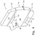
- FIG. 6is a perspective view of the cushion assembly configured to be supported on the foot deck section, the cushion assembly including a protrusion configured to be received by the stowable foot deck section to activate a locking mechanism to secure the stowable foot deck section in use position on the birthing bed;
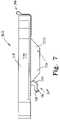
- FIG. 7is a side view of the cushion assembly of FIG. 6 ;
- FIG. 8is a bottom view of a storage structure of the cushion assembly of FIG. 6 ;
- FIG. 9is a side view of the storage structure of FIG. 8 ;
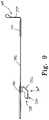
- FIG. 10is a perspective view of a portion of a birthing bed having an embodiment of a guide system which guides the stowable foot deck section from a use position to be supported on a storage structure
- FIG. 11is a perspective view of a portion of the birthing bed of FIG. 2 with portions removed, perspective view showing a receiver mounted to a frame of the birthing bed, the receiver configured to receive a portion of the stowable foot deck section in a cantilevered configuration;
- FIG. 12is a view similar to FIG. 11 , FIG. 12 showing an alternative embodiment of receiver configured to receive a removable foot deck section;
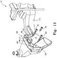
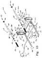
- FIG. 13is an exploded perspective assembly view of a structure coupled to a portion of the birthing bed of FIG. 2 , the structure configured to support the stowable foot deck section in a stowed position;
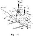
- FIG. 14is a perspective view of a portion of the storage structure of FIG. 13 ;
- FIG. 15is an exploded perspective assembly view of the portion of the storage structure of FIG. 14 ;
- FIG. 16is an exploded assembly view of a portion of the birthing bed of FIG. 1 with a removable foot deck section;
- FIG. 16Ais an enlarged view of a portion of FIG. 16 enclosed in a circle 16 A;
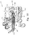
- FIG. 17is a perspective view of the removable foot deck section stored positioned on a floor in an out-of-the-way position;
- FIG. 18is a side view of the removable foot deck section
- FIG. 19is a side view of a tab of the removable foot section of FIG. 16 positioned to engage the receiver shown in FIG. 12 ;
- FIG. 20is a cross-sectional view of the receiver of FIGS. 12 , 16 , and 19 The cross-section taken along lines 20 - 20 of FIG. 19 ;
- FIG. 21is a perspective view of a portion of a birthing bed including another embodiment of a foot deck section, the removable foot deck section including a locking mechanism to secure the removable foot deck section to a frame of the birthing bed;
- FIG. 22is a perspective view of the removable foot deck section of FIG. 21 , the foot deck section viewed from below;
- FIG. 23is a perspective view of a portion of a frame of the birthing bed of FIG. 21 , the frame configured to be engaged by the locking mechanism to secure;
- FIG. 24is a perspective view of a portion of a birthing bed having yet another embodiment of a removable foot deck section
- FIG. 25is a perspective view of yet another embodiment of removable foot deck section, the foot deck section having a self-deploying stand to support the foot deck section when it is positioned on the floor;
- FIG. 26is a perspective view of yet another removable foot deck section, the foot deck section including a deployable support frame with caster wheels such that the foot deck section may be rolled away from a birthing bed to which the foot deck section is engaged;
- FIG. 27is a perspective view of a portion of the guide shown in FIG. 10 ;
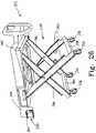
- FIG. 28is a side view of the guide of FIG. 27 ;
- FIG. 29is a cross-sectional view of the guide of FIG. 27 taken along lines 29 - 29 in FIG. 28 ;
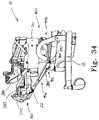
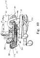
- FIGS. 30-40are various perspective views of another embodiment of a birthing bed with portions removed, the birthing bed having a structure and guide system to support a stowable foot deck section in a use position and in a stowed position;
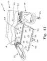
- FIG. 41is perspective view of another embodiment of birthing bed, the birthing bed having a stowable foot deck section that folds and articulates to a stowed position;
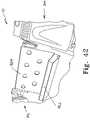
- FIG. 42is a perspective view of the stowable foot deck section of FIG. 41 in a stowed position.
- FIG. 43is a perspective exploded assembly view of another embodiment of a storage structure configured to support a foot deck section suspended from a frame of a patient-support apparatus.
- a birthing bed 10comprises a head deck section 12 , seat deck section 14 , and a removable foot deck section 16 as shown in FIG. 1 .
- the birthing bed 10further comprises a base frame 18 supporting an intermediate frame 20 that supports the head deck section 12 and seat deck section 14 .
- the head deck section 12 and seat deck section 14are articulable relative to the intermediate frame 20 to adjust the position of a patient occupying the birthing bed 10 .
- the foot deck section 14is supported on a support frame 22 that is supported by the intermediate frame 20 .
- the support frame 22moves vertically as depicted by arrow 24 in FIG. 1 to adjust to a plurality of positions including positions in which the foot deck section 16 is vertically spaced from the seat deck section 14 . This allows a caregiver or patient to adjust the birthing bed 10 to a plurality of positions during labor and delivery.
- the birthing bed 10comprises a mattress 25 that is supported on the head deck section 12 and seat deck section 14 .
- the mattress 25comprises a v-shaped cavity 26 along the edge of the mattress 25 adjacent the foot deck section 16 .
- a cushion assembly 28is supported on the foot deck section 16 and comprises a protrusion 30 that is configured to be received in the cavity 26 to form a continuous support surface for a patient when the foot deck section 16 is vertically aligned with the seat deck section 14 .
- the birthing bed 10also comprises two articulable foot supports 32 and 34 . Foot support 32 is positioned to support a patient's right foot when in use while foot support 34 is positioned to support a patient's left foot when in use.
- the birthing bed 10is configured to permit a caregiver access to a patient seated on the mattress 25 and supported on seat deck section 14 .
- Foot deck section 16is supported on the support frame 22 and moveable with the support frame 22 as the support frame 22 moves vertically relative to the intermediate frame 20 .
- FIG. 16removable foot deck section 16 and a portion of birthing bed 10 are shown in an exploded assembly view.
- Seat deck section 14comprises an upper deck 36 which is supported on a lower deck 38 .
- Lower deck 38includes first and second pivots 40 and 42 respectively which cooperate to define an axis of rotation about which seat deck section 14 pivots relative to intermediate frame 20 .
- Support frame 22is supported relative to intermediate frame 20 and moves vertically relative to intermediate frame 20 as depicted by arrow 24 .
- Support frame 22is driven by a drive mechanism (not shown) which utilizes a DC drive to articulate an articulating mechanism 44 to control movement of support frame 22 .
- the operation of birthing bed 10 including the articulation of support frame 22is consistent across all embodiments.
- support frame 22may be engaged by a receiver to change the configuration of the birthing bed 10 such that alternative embodiments of foot support decks may be employed on the birthing bed 10 .
- a receiver 46is coupled to support frame 22 by three bolts 48 .
- Receiver 46is configured to assist a user, such as a caregiver, to engage a removable foot deck section such as foot deck section 16 to support frame 22 by guiding a support plate 50 to proper engagement with receiver 46 to support foot deck section 16 in cantilever from support frame 22 .
- a second receiver 52is positioned on support frame 22 and is positioned laterally opposite of receiver 46 .
- Receiver 52is also secured to support frame 22 by three bolts 48 and receiver 50 is positioned to receive a second support plate 54 which is positioned on foot deck section 16 laterally opposite of support plate 50 .
- foot deck section 16When support plates 50 and 54 are engaged with receivers 46 and 52 respectively, foot deck section 16 is supported in cantilever from support frame 22 . As will be discussed in further detail below, the weight of foot deck section 16 , cushion assembly 28 , and the weight of a portion of a patient supported thereon, serves to increase the force with which support plates 50 and 54 are engaged with the receivers 46 and 52 .
- Receiver 46has an upper surface 56 which transitions to an incline surface 58 which transitions to an engagement surface 60 .
- Receiver 46further includes a first protrusion 62 and a second protrusion 64 .
- first protrusion 62is positioned at a foot end to side of receiver 46 and protrusion 64 is positioned at a head end of receiver 46 .
- Protrusions 62 and 64thereby serve as longitudinal barriers for support plate 50 when support plate 50 is engaged with receiver 46 .
- support plate 50is narrower at a lower portion and widens as it progresses vertically upwardly, as shown in FIG. 19 . This tapering effect assists a caregiver in properly positioning the removable foot deck section 16 longitudinally as the foot deck section 16 is being positioned to engage with receivers 46 and 52 .
- support plate 50includes a surface 66 which engages a surface 68 of the second protrusion 64 as support plate 50 is engaged with receiver 46 .
- Support plate 50also includes a surface 70 which engages a surface 72 of receiver 46 when support plate 50 is engaged with receiver 46 .
- Support plate 50has a vertical axis 74 and surfaces 66 and 70 are not parallel to vertical axis 74 or to each other. As support plate 50 is lowered in the direction of arrow 76 surfaces 66 and 70 engage surfaces 68 and 72 respectively such that support plate 50 is frictionally engaged with receiver 46 thereby securing removable foot deck section 16 to the birthing bed 10 .
- an outer surface 78(not shown in FIGS.
- support plate 50is a mirror image to support plate 54 .
- Support plate 54comprises a main portion 102 with an outer member 104 which is positioned to engage receiver 52 and act as a bearing surface to reduce noise during the insertion of support plate 50 into receiver 52 , as well as to reduce noise which may occur when foot deck section 16 is moved due to patient movement on foot support deck 16 .
- Support plate 50also includes a main portion 106 and an outer member 108 .
- Surface 70 of support plate 50is formed to include a protrusion 80 which acts as a hook to prevent inadvertent removal of foot deck section 16 from receivers 46 and 52 . If the foot end of foot deck section 16 is lifted, protrusion 80 engages a lower surface 82 of first protrusion 62 of receiver 46 . Thus, a person who is not familiar with the operation of foot deck section 16 is prevented from removing foot deck section 16 . In normal operation, a user grips two handles 84 and 86 which are shaped and positioned to cause the weight of foot deck section 16 to rotate to prevent protrusion 80 from clearing surface 82 of first protrusion 62 . Foot deck section 16 includes a main portion 88 and handle 84 and 86 are coupled to opposite sides of main portion 88 by fasteners 90 .
- Foot deck section 16further includes four extensions 92 , 94 , 96 , and 98 coupled to main portion 88 and extending laterally therefrom.
- Support bracket 50is coupled to extensions 96 and 98 and support bracket 54 is coupled to extensions 92 and 94 .
- Extensions 92 , 94 , 96 , and 98each have a through-hole 100 .
- support plate 54is shown to include a pair of flanges 110 and 112 which are coupled to main portion 102 . Two through-holes are formed in each of the flanges 110 and 112 respectively. Through-hole 114 and through-hole 116 are each formed in flange 110 .
- Through-hole 118 and through-hole 120are each formed in flange 112 .
- Through-hole 114is positioned vertically above through-hole 118 such that the centerlines of the through holes form an axis 122 .
- through-hole 116is positioned vertically above through-hole 120 such that the centerlines of those through-holes form an axis 124 .
- the axis 122is positioned such that a fastener 100 passes through flange 110 through protrusion 92 and through flange 112 along axis 122 and a second fastener 100 passes along axis 124 through flange 110 , protrusion 94 , and flange 112 .
- Support bracket 50includes two flanges 130 and 132 and is coupled to protrusions 96 and 98 in a manner that is similar to manner in which bracket 54 is coupled to protrusions 92 and 94 and will not be discussed in further detail.
- Support bracket 54further includes a glide 134 which is coupled to main portion 102 and positioned to cover a lower surface 138 of main portion 102 .
- Glide 134acts as a bearing as support bracket 54 is engaged with receiver 52 to reduce the potential for noise during the engagement of support bracket 54 with receiver 52 .
- Support bracket 50also includes a glide 140 coupled to main portion 106 and which acts in a manner or similar to glide 134 of support bracket 54 .
- Foot deck section 16further includes a stand 142 which is coupled to main portion 88 by two fasteners 144 .
- Stand 142is illustratively embodied as a wire-form which is configured to support foot deck section 16 in a standing position.
- a stand 142is coupled to a foot deck section 144 and supports the foot deck section 144 in a standing position such that a cushion assembly 146 is spaced apart from the floor to prevent linens supported on the cushion assembly 146 from being contaminated by touching the floor.
- the illustrative foot deck section 144is similar to foot deck section 16 , but the foot deck section 144 has two grip handles 148 and 150 coupled to a main portion 152 . Grip handles 148 and 150 are positioned such that a caregiver may utilize the grip handles 148 and 150 to reposition birthing bed 10 by rolling the birthing bed 10 on casters 154 coupled to the base 18 of birthing bed 10 .
- foot deck section 16further includes a handle 156 coupled to main portion 88 .
- Handle 156is usable by a caregiver to reposition the birthing bed 10 by rolling it on its casters 154 .
- Handle 156also serves as a stand to support foot deck section 16 in a standing position with handle 156 engaging the floor.
- a placenta basin 158is supported on two racks 160 and 162 which are coupled to support frame 22 vertically below receivers 46 and 52 respectively.
- Racks 160 and 162are illustratively embodied as wire forms and are configured to receive flange portions 166 and 168 of placenta basin 158 respectively.
- a shroud 164is coupled to support frame 22 and has a shape which is configured to engage a front portion 170 of placenta basin 158 so that shroud 164 and placenta basin 158 cooperate to guide waste materials into the placenta basin 158 .
- Rack 116includes two extensions 172 and 174 which are received in two holes (not shown) in support frame 22 such that rack 116 is coupled to support frame 22 by a frictional interference fit. In some embodiments, an adhesive may be added to secure rack 116 to support frame 22 . Similarly, rack 162 includes two extensions 176 and 178 which are received in holes (not shown) in support frame 22 .
- Foot deck section 16further includes a support member 180 coupled to main portion 88 and configured to provide support for a protrusion on a cushion assembly supported on foot deck section 16 when foot deck section 16 is engaged with support frame 22 .
- Support member 180is illustratively embodied as a wire form having a V-shape and positioned to be received in a V-shaped cavity 182 formed an upper deck 36 of seat section 14 .
- Support member 180is coupled to main portion 88 by two fasteners 184 and washers 186 .
- the cavity formed in upper deck 36 of seat section 14may be a U-shaped cavity and support 180 may be replaced with another support member which is configured to be received within the U-shaped cavity and support a U-shaped protrusion of a cushion assembly supported on a foot deck section configured to be received in the U-shaped cavity.
- Foot deck section 144 shown in FIGS. 17-18is similar to foot deck section 16 and illustrates the manner in which a cushion assembly, such as cushion assembly 146 may be coupled to foot deck section 144 or other embodiments of foot deck sections, such as foot deck section 16 .
- Cushion assembly 146includes a flap 188 which extends over the side of foot deck section 144 and includes two snap portions 190 which engage complementary snap portions 192 .
- Snap portions 192are shown in FIG. 16 which shows the engagement of snap portions 192 with main portion 88 of foot deck section 16 .
- another flap complementary to flap 188 and positioned laterally on the opposite side of cushion assembly 146includes a pair of snap portions 190 coupled to another pair of snap portions 192 .
- cushion assembly 146is coupled to foot deck section 144 and maintains engagement with foot deck section 144 when foot deck section 144 is removed from engagement with receivers 46 and 52 .
- a cushion assemblysuch as cushion assembly 146 could be coupled to foot deck section 16 .
- Foot deck section 144includes a pair of handles with one of the handles 194 shown in FIGS. 17 and 18 .
- the handles including handle 194are flexible and are positioned such that when a user lifts foot deck section 144 off from support frame 22 of birthing bed 10 , the weight of foot deck section 144 urges the foot deck section to rotate with stand 142 in a vertically lowered orientation so that a caregiver may position foot deck section 144 in a standing position as shown in FIG. 17 .
- foot deck sections 16 and 144employ a passive locking approach to secure the foot deck sections 16 and 144 to birthing bed 10 .
- a foot deck section 196is removable from support frame 22 and includes a locking mechanism to positively secure foot deck section 196 to support frame 22 .
- Foot deck section 196includes a main portion 198 with two support bracket assemblies 200 and 202 coupled to main portion 198 .
- support frame 22 in the illustrative embodiments of FIGS. 21-23is coupled to hospital bed 10 as described elsewhere in this disclosure.
- Support bracket 200rests on a portion of a receiver 204 and support bracket 202 rests on a portion of a receiver 206 when foot deck section 196 is positioned on support frame 22 .
- the engagement of support bracket 202 to receiver 206is similar to the engagement of support bracket 200 to receiver 204 and will not be discussed in detail.
- the discussion of the engagement of support bracket 200 to receiver 204should be extended to the engagement of support bracket 202 to receiver 206 .
- Receiver 204includes an upper portion 208 and a lower portion 210 .
- Upper portion 208is formed to include a protrusion 212 having an upper surface 214 , a guide surface 216 , and a vertical surface 218 .
- Extension 212extends over an upper surface 220 of lower portion 210 to form and undercut 222 which is configured to receive a roller 224 coupled to a main portion 226 of support bracket 200 .
- support bracket 200includes a flange 228 which is positioned to engage upper surface 220 of lower portion 210 of receiver 204 .
- roller 224is positioned in to undercut 222 and flange 228 rest on upper surface 220 of lower portion 210 such that foot deck section 196 is supported in a cantilevered orientation from support frame 22 .
- Foot deck section 196further includes a locking mechanism 230 which transfers motion from a pair of handles 232 and 234 to rotate a pair of hooks which engage a cavity in lower portion 210 to secure foot deck section 196 to support frame 22 .
- latch hook 236rotates relative to support bracket 200 .
- latch hook 236is positioned above the cavity 238 in the lower portion 210 and rotates such that a barb 241 is positioned within cavity 240 beneath a surface 242 .
- Cavity 240 and surface 242cooperate to define a latch block 243 which is engaged by barb 241 to secure foot deck section 196 to support frame 22 .
- Handles 232 and 234are coupled to a shaft 242 which spans the width of the main portion 198 of foot deck section 196 .
- Shaft 242is supported on main portion 198 through a pair of bearings 244 which permit shaft 242 to rotate about its longitudinal length relative to main portion 198 as depicted by arrow 246 .
- Locking mechanism 230further includes an arm 248 coupled to shaft 242 which rotates with shaft 242 when shaft 242 is rotated by arms 232 and 234 .
- a link 250is pivotably coupled to arm 248 and is pivotably coupled to a second arm 252 .
- Arm 252is coupled to a shaft 254 and latch hook 236 is coupled to shaft 254 and rotates about the longitudinal length of shaft 254 as depicted by arrow 256 .
- Shaft 254is coupled to another shaft 258 through a coupler 260 which is coupled to each of the shafts by a fastener 262 such that rotation of shaft 256 is transferred to shaft 258 which thereby rotates another hook (not shown) positioned laterally opposite latch hook 236 .
- Shafts 254 and 258rotate relative to support plates 200 and 202 respectively and are supported by bearings 244 . Because link 250 is pivotably coupled to throws 248 and 252 at a position that is offset from the longitudinal axis of shafts 242 and 254 , rotation of shaft 242 is transferred to shaft 254 and thereby shaft 258 .
- handles 232 and/or 234rotates latch hook 236 to engage with receiver 204 .
- handles 232 and 234are rotated downwardly, they move to an out-of-the-way position in which handles 232 and 234 are positioned below an upper surface of a cushion assembly supported on foot deck section 196 . If the handles are rotated upwardly in the direction of arrow 264 in FIG. 21 , latch hook 236 disengages receiver 200 and foot deck section 196 is free to be removed from engagement with receivers 200 and 202 .
- a foot deck section 266supports a cushion assembly 268 and is coupled to support frame 22 of birthing bed 10 .
- a handle 273includes a main portion 270 and a grip portion 272 .
- Handle 273is actuable in the direction of arrow 274 to move to a stowed position with the grip portion 272 stowed at the foot end of deck section 266 with grip portion positioned adjacent a handle 271 .
- the foot deck section 266employs a locking mechanism similar to locking mechanism 230 of the illustrative embodiment of FIGS. 21-23 , but the direction of travel of handle 273 is reversed as compared to handles 232 and 234 of foot deck section 196 .
- a removable foot deck section 280includes a main portion 282 and two support brackets 284 , 286 coupled to main portion 282 and configured to engage receivers 52 and 46 of the illustrative embodiment of FIG. 16 , respectively.
- Foot deck section 280includes a handle 288 coupled to main portion 282 and functions similarly to handle 156 of foot deck section 16 .
- foot deck section 280functions similarly to foot deck section 16 .
- foot deck section 280includes a three-point stand 290 which deploys when foot deck section 280 engages the floor.
- Stand 290includes an upper bracket assembly 292 which is coupled to a cross-member 294 of the main portion 282 of foot deck section 280 .
- Bracket assembly 292includes two receivers 296 and 298 coupled by a link 300 such that the receivers 296 and 298 maintain a constant relative spacing. Bracket assembly 292 is pivotably coupled to cross-member 294 and pivots relative to cross-member 294 as depicted by an arrow 302 .
- Stand 290further includes two legs 304 and 306 , with leg 304 being engaged with receiver 296 and leg 306 been engaged with receiver 298 such that legs 304 and 306 move with bracket assembly 292 .
- a collar 308is coupled to leg 304 and is configured to receive a link 312 for pivotable movement relative to collar 308 and thereby leg 304 .
- a collar 310is coupled to leg 306 and is configured to receive a link 314 such that the link 314 is pivotable relative to collar 310 .
- Links 312 and 314are coupled to a bracket 316 .
- a bias member 318is also coupled to bracket 316 and is interposed between links 312 and 314 .
- Bias member 318is coupled at an end opposite bracket 316 to cross-member 320 of the main portion 282 of foot deck section 280 .
- a flange 322is also coupled to bracket 316 and is configured to engage with the floor when foot deck section 280 is lowered to the floor.
- a foot 324is coupled to flange 322 and bracket 316 . Foot 324 is flexible and has a high coefficient of friction so that when foot 324 engages the floor, it provides resistance to deploy stand 290 .
- bias member 318urges bracket 316 to a stowed position wherein the bias member 318 pulls legs 304 and 306 upwardly to a stowed position against the bottom of main portion 282 of foot deck section 280 .
- bias member 318deflects in the direction of arrow 326 . Because links 312 and 314 are rigid and fixed in length, deflection of bias member 318 causes links 312 and 314 to act upon legs 304 and 306 respectively to urge the legs 304 , 306 into the deployed position as shown in FIG. 25 .
- foot deck section 280rests on two glides 328 and 330 coupled to legs 304 and 306 respectively and foot 324 . If bias member 318 is sufficiently deflected, foot deck section 280 may also rest on support brackets 284 and 286 . When foot deck section 280 is lifted from the floor, bias member 318 urges bracket 316 in the direction opposite of arrow 326 and thereby links 312 and 314 pull legs 304 and 306 into the stowed position tucked against the lower side of main portion 282 .
- a removable foot deck section 332is supported on a scissors frame 334 such that foot deck section 332 can be rolled away from a patient-support apparatus, such as birthing bed 10 .
- Scissors frame 334includes four casters 336 , two of which are coupled to a lower member 338 and two of which are coupled to a lower member 340 .
- Scissors mechanism 334further includes two legs 342 , 342 coupled to lower member 338 and pivotably coupled at a head end of a main portion 344 of foot deck section 332 .
- Two legs 346 , 346are pivotably coupled to a cross-member 348 near the foot end of main portion 344 such that legs 346 are pivotable relative to main portion 344 . Additionally, one of each of the legs 342 is pivotably coupled to one of the other pair of legs 346 to form the scissors frame 334 .
- Scissors frame 334is manually deployed to engage the floor when a caregiver wants to remove foot deck section 332 from engagement with birthing bed 10 . Additionally, scissors frame 334 can be lifted to a stowed position manually when foot deck section 332 is engaged with birthing bed 10 .
- a support bracket 350is coupled to main portion 344 and is configured to slide onto a receiver (not shown) coupled to support frame 22 of birthing bed 10 .
- a matching support bracketis positioned laterally opposite support bracket 350 such that when the support brackets are engaged with the receivers, foot deck section 332 is supported in a cantilevered configuration from support frame 22 .
- Support bracket 350includes a bias member 352 which deflects when support bracket 350 is engaged with a receiver on support frame 22 until bias member 352 is received in a cavity in the receiver.
- the cavityis complementary to bias member 352 and maintains foot deck section 332 in engagement with support frame 22 until sufficient force is applied to overcome the bias of bias member 352 to remove the foot deck section 332 from support frame 22 .
- a foot deck section similar to foot deck section 16may have a stand such as stand 142 omitted and may be supported in a standing orientation by a structure similar to stand 290 as disclosed in the illustrative embodiment of FIG. 25 .
- a foot deck sectionsuch as foot deck section 16 may be configured to employ the locking mechanism disclosed in the illustrative embodiment of FIGS. 21-23 .
- foot deck sectionshave been disclosed which are removal from birthing bed 10 and storable in a position spaced apart from birthing bed 10 .
- cushion assembly 362positioned on the foot deck section 362 .
- Cushion assembly 362comprises an actuator 364 that extends from a bottom surface 366 of cushion assembly 362 (best seen in FIG. 6 ) and is received in an aperture 368 in an upper surface 370 of foot deck section 360 .
- the actuator 364retains cushion assembly 362 on foot deck section 360 and activates a locking mechanism 372 (best seen in FIG. 4 ) which extends two pins 374 and 376 laterally outwardly from the foot deck section 360 to engage with a channel 378 in receiver 380 coupled to support frame 22 (refer to FIG. 11 ).
- the receiver 380is positioned on the patient right side of birthing bed 10
- a second receiver 382is positioned on the patient left side of birthing bed 10 as shown in FIG. 2 .
- the foot deck section 360engages with receivers 380 and 382 through two sets of rollers 384 , 386 and 388 , 390 with rollers 384 and 386 positioned on the patient right side of foot deck section 360 and rollers 388 and 390 positioned on the patient left side of foot deck section 360 .
- Rollers 384 , 386 , 388 and 390are secured to foot deck section 360 by a retainers 900 , 902 , 904 and 906 each of which includes a flange 910 which is received in an undercut 379 formed in channel 378 . Referring now to FIG. 11 , channel 378 intersects a channel 392 . When foot deck section 360 is positioned on support frame 22 , roller 384 is positioned in channel 378 .
- Roller 386is positioned on a surface 394 on receiver 380 and the foot deck section 360 is pivoted about roller 386 such that roller 384 travels in channel 378 until roller 384 engages an end 396 of channel 378 .
- foot deck section 360With roller 386 resting on surface 394 and roller 384 engaged with end 396 , foot deck section 360 is supported in cantilever from support frame 22 . However, lifting of the foot deck section 360 will result in the foot deck section 360 moving relative to the receiver 380 .
- pin 374is extended into a blind cavity 398 formed in an inner surface 90 of the receiver 380 . Engagement of pin 374 with cavity 398 prevents rotation of foot deck section 360 relative to receiver 380 . As will be discussed in further detail below, pin 374 extends from foot deck section 360 when cushion assembly 362 is positioned on foot deck section 360 such that the activator 364 of cushion assembly 362 activates a locking mechanism 372 to extend pins 374 and 376 . This secures foot deck section 360 and cushion assembly 362 relative to support frame 22 when the foot deck section 360 is positioned on support frame 22 in use.
- foot deck section 360When not in use, foot deck section 360 is stowable on a storage structure 400 as shown in FIGS. 30-40 so that a placenta basin 402 of the foot deck section 360 is positioned for use during the labor and delivery process as shown in FIG. 2 .
- a portion of storage structure 400is shown in FIG. 13 .
- Storage structure 400is configured to receive and support foot deck section 360 thereon in a stowed position.
- storage structure 400is configured to deflect if downwardly if a caregiver steps on foot deck section 360 while the section 360 is in the stowed position to prevent damage to the section 360 .
- a portion of storage structure 400moves along the longitudinally relative to the length of birthing bed 10 to clear a transverse beam 404 of the base 18 .
- storage structure 400includes a guide 406 which is supported on frame 407 which includes a pair of extensions 408 and 410 .
- Guide 406includes a pair of plates 412 and 414 which are configured to secure to receiver 380 and 382 respectively.
- Guide 406further includes a pair of arms 416 and 418 which are coupled to plates 412 and 414 respectively. Arms 416 and 418 are interconnected by a cross-member 420 which is positioned within extensions 408 and 410 and supported by extensions 408 and 410 for movement relative thereto in the direction of arrows 422 and 424 . Movement of guide 406 relative to frame 407 is illustrated in FIGS. 39 and 40 .
- guide 406moves relative to frame 407 when storage structure 22 moves vertically relative to intermediate frame 20 .
- Plate 412includes a through-hole 426 and plate 414 includes a through-hole 428 the centerlines of which cooperate to define an axis 430 of rotation about which guide 406 rotates as support frame 22 moves relative to intermediate frame 20 .
- Frame 407further includes a shaft 432 coupled to two plates 434 and 436 .
- Extension 408is coupled to plate 434 and extension 410 is coupled to plate 436 .
- Plate 434has an upper surface 438 and plate 436 has an upper surface 440 , each of which is configured to engage a lower surface 442 of a cross-member 444 of a bias assembly 446 .
- Bias assemblyis configured to maintain frame 407 in an orientation in which extensions 408 and 410 are in a generally horizontal orientation under normal conditions and to allow frame 407 to deflect relative to bias assembly 446 when a load is applied to the frame 407 distal to cross-member 444 . For example, if foot deck section 360 is supported on frame 407 and a user steps on foot deck section 360 , bias assembly 446 will permit frame 407 to deflect under the load of the user in the direction of arrow 448 shown in FIG. 13 .
- Bias assemblyincludes two extension springs 450 and 452 which bias against cross-member 444 when assembled to two pins 454 and 456 respectively.
- Pins 454 and 456are received on opposing ends of shaft 432 of frame 407 .
- Shaft 432is secured to bias assembly 446 by two fasteners 458 , 458 which are received in the ends of shaft 432 .
- Bias assembly 446also includes two brackets 460 and 462 engaged at opposite ends with cross-member 444 .
- Two bearings 464engage two through-holes (not shown) in cross-member 444 and provide a bearing interface between the cross-member 444 and the pins 454 and 456 and the extension springs 450 and 452 .
- Pins 454 and 456pass through extension springs 450 and 452 respectively.
- Pin 454includes a threaded portion 466 and pin 456 includes a threaded portion 468 each of which are configured to receive a washer 470 and nut 472 biases surfaces 438 and 440 of plates 434 and 436 respectively against lower surface 442 of cross-member 444 .
- the compression of extension springs 450 and 452defines the amount of bias exerted by bias assembly 446 on frame 407 .
- cross-member 444is free to move relative to brackets 460 and 462 .
- frame 407rotates about shaft 432 and surfaces 438 and 440 are urged against surface 442 .
- cross-member 444compresses springs 450 and 452 to allow frame 407 to deflect.
- frame 407is urged to return to a position in which extensions 408 and 410 are in a generally horizontal orientation.
- Storage structure 400is received in tube members 474 and 476 of intermediate frame 20 and is moveable longitudinally relative to intermediate frame 20 .
- Storage structure 400comprises two hanger assemblies 478 and 480 to which brackets 460 and 462 are coupled respectively.
- Hanger assemblies 478 and 480have identical structures and will be described generally with reference to hanger assembly 478 .
- Hanger assembly 478includes a rod 482 and a hanger bracket 484 which includes a tubular member 486 through which rod 482 is received.
- a fastener 488is threaded through tubular member 486 and engages rod 482 to secure hangar bracket 484 to rod 482 .
- hanger bracket 484is fixed to and moves with rod 482 .
- Hanger assembly 478further includes two guides 490 , 490 , each of which is coupled to an end of rod 482 by a fastener 492 such that when hanger assembly 478 is assembled, guides 490 , 490 are positioned to support rod 482 within member 474 of intermediate frame 20 .
- Guide 490is sized to be received in an inner space of member 474 with sufficient clearance to move along the length of member 474 .
- Storage structure 400further includes a pair of extension springs 494 , 494 one of which is positioned between a hanger assemblies 478 and 480 and intermediate frame 20 at a foot end of birthing bed 10 , the extension springs 494 , 494 positioned in members 474 and 476 respectively.
- the extension springs 494 , 494urge hanger assemblies 478 and 480 toward the head end of birthing bed 10 .
- Brackets 460 and 462are secured to hanger assemblies 478 and 480 through a hanger block 496 which is formed to include a through-hole 498 parallel to the longitudinal length of tubular member 486 .
- Bracket 460is formed to include two through-holes 500 and 502 in opposing flanges 504 and 506 of bracket 460 .
- Hanger block 496is sized to be received between flanges 504 and 506 such that through-hole 498 aligns with through-holes 500 and 502 .
- a fastener 508illustratively embodied as a carriage bolt, passes through the through-holes 500 , 498 and 502 and is secured by a nut 510 to couple bias assembly 446 to hanger assembly 478 .
- Bracket 462is secured to hanger assembly 484 in a similar manner.
- Fastener 508passes through a through-hole 512 in flange 516 of bracket 462 , a through-hole 498 in hanger block 496 of hanger assembly 484 , and a through-hole 514 in flange 518 of bracket 462 and is secured by a nut 510 .
- bias assemblyfurther includes two bearing plates 520 and 522 coupled to outer surfaces of brackets 460 and 462 respectively by fasteners 458 .
- Each of the bearing plates 520 and 522operate in a similar manner with the two being mirror images of each other.
- the bearing plateis formed to include an angled surface 524 .
- plates 434 and 436are formed to include angled surfaces 526 and 528 which are generally parallel to angled surface 524 on bearing plate 522 and a complementary surface (not shown) on bearing plate 520 .
- the angled surfaces 524 , 526 , and 528are positioned such that when intermediate frame 20 is lowered, the surfaces 524 , 526 , and 528 engage an intersection 534 of surfaces 532 and 536 of a cross-beam 530 of base 18 . Engagement of surfaces 524 , 526 , and 528 with cross-beam 530 urges storage structure 400 toward the foot end of birthing bed 10 and overcomes the bias of extension springs 494 causing the hanger assemblies 478 and 480 to move longitudinally to prevent damage to foot deck section 360 and storage structure 400 due to a lack of clearance between storage structure 400 and cross-beam 530 . When intermediate frame 20 is raised, extension springs 494 urge storage structure 400 to a home position.
- a storage structure 592is supported from the intermediate frame 20 and moveable relative thereto.
- the storage structure 592comprises two springs 596 and 598 that are each coupled at one end to members 474 and 476 respectively.
- the springs 596 and 598are each coupled to a tubular rod 604 and 606 respectively as well.
- the tubular rods 604 and 606each support tubes 600 and 602 respectively.
- Springs 596 and 598bias storage structure 592 and urge storage structure 592 toward the head end of the birthing bed 10 .
- the storage structure 592further comprises two support brackets 618 and 620 that comprise tubes 600 and 602 respectively.
- Each support bracket 618 and 620has a hanger 622 and 624 respectively and each hanger 622 and 624 has a mount block 626 and 628 respectively secured to the hangars 622 , 624 , the mount blocks 626 and 628 configured to limit rotation of a torsion spring assembly 630 relative to the hangers 622 and 624 .
- the torsion spring assembly 630comprises an outer tube 632 , a plurality of flexion members 634 , a torsion collar 636 , and a retaining collar 638 .
- the flexion members 634are received through the length of outer tube 632 and received in a square aperture 640 in an end 642 of outer tube 632 .
- the retaining collar 638is coupled to the end 642 of outer tube 632 by a pin 644 once outer tube 632 has passed through an aperture 646 in hanger 624 .
- the flexion members 634are received in a through-hole 648 of torsion collar 636 , the through-hole 648 having a square cross-section.
- the mount block 626comprises a pin receiving hole (not shown) which receives a pin 650 .
- the pin 650is also received in one of a series of holes 652 in an outer annular surface 654 of torsion collar 636 .
- the connection of pin 650 to torsion collar 636 and mount block 626fixes the torsion collar 636 relative to the support bracket 618 and, thereby, the intermediate frame 20 .
- the outer tube 632has a longitudinal axis 656 about which the outer tube 632 rotates.
- Outer tube 632also comprises a positioning flange 658 that engages with a surface 660 of hanger 622 to prevent lateral movement of the torsion spring assembly 630 in the direction of an arrow 660 .
- Another positioning flange 662is positioned along outer tube 632 adjacent an inner surface (not shown) of hanger 624 to prevent lateral movement of the torsion spring assembly 630 in the direction of an arrow 664 .
- torsion spring assembly 630is retained on hanger 622 by torsion collar 636 and positioning flange 658 and retained on hanger 624 by position flange 662 and retaining collar 638 .
- the outer tube 632still further comprises two mounts 666 and 668 that are positioned to be vertically below the longitudinal axis 656 .
- the mount 666receives a bracket 670 that is coupled to mount 666 by a pin 672 .
- a bracket 674is coupled to mount 668 by a pin 676 .
- Each bracket 670 and 674are coupled to a rod 678 and 680 respectively.
- Each rod 678 and 680have a pin 682 and 684 respectively coupled to the rods 678 and 680 , the pins 682 and 684 serving as retainers.
- storage structure 692deflects under load. For example, if a load is placed on storage structure 692 , torsion spring assembly 630 rotates about axis 656 as depicted by arrow 710 . While the end of torsion spring assembly 630 where torsion collar 636 is fixed to mount block 626 is restrained from rotating, torsion members 634 flex at end 642 . The torsion members 634 are engaged with outer tube 632 at aperture 640 but outer tube 632 is free to rotate relative to torsion collar 636 . Therefore, outer tube 632 rotates relative to brackets 622 and 624 allowing rods 678 and 680 to pivot about axis 656 .
- FIG. 4shows the storage structure 592 in an undeflected position.
- the brackets 622 and 624engage cross-beam 530 of base 18 and are urged away from cross-beam 530 to prevent damage to storage structure 592 due to interference between brackets 622 and 624 with cross-beam 530 .
- storage structure 592operates in a manner similar to storage structure 400 to permit rotation of a frame of the storage structure relative to the intermediate frame and longitudinal movement of the storage structures 400 and 592 relative to the intermediate frame.
- the bias assembly 446 of storage structure 400may be omitted and replaced with the torsional spring assembly 630 .
- the hanger assemblies 478 and 480may be omitted and replaced with a structure utilizing the springs 96 and 98 of storage structure 592 .
- guide 406is omitted and replaced with a pair of guide members.
- a guide member 100is shown in FIG. 10 engaged with a receiver 380 .
- Another guide memberengages receiver 382 and is substantially similar to guide member 1000 but in a mirror image and the discussion of guide member 1000 will be sufficient to understand the disclosure.
- Guide member 1000is pivotable about a pivot 1004 .
- Guide member 1000is supported on a structure similar to storage structure 400 and is supported on frame 407 by a cross-member 1002 .
- Cross-member 1002is secured to guide member 1000 such that rollers 384 and 386 and retainers 900 and 902 are guided down a channel 1006 as foot deck section 360 is moved to a stowed position. Referring now to FIGS.
- guide member 1008which is the opposite hand of guide member 1000 is shown in detail.
- Guide member 1008includes a channel 1010 and guide member pivots relative to receiver 382 about a mount hole 1012 as depicted by arrow 1014 .
- guide member 1008includes a trough 1016 formed in channel 1010 .
- Trough 1016is configured to receive a flange 910 of the retainers 900 and 902 to prevent foot deck section 360 from moving laterally as foot deck section 360 is moved to a stowed position.
- Rollers 384 and 386roll along a surface 1020 preventing flanges 910 of retainers 900 and 902 from contacting metal surfaces within trough 1016 .
- the foot support cushion assembly 362comprises a central cushion 716 and side cushions 718 and 720 .
- the cushions 716 , 718 and 720are all covered with a single covering comprising a urethane-coated fabric. However, cushions 718 and 720 are pivotable relative to cushion 716 .
- the cushion assembly 362also comprises a flap 722 and a flap 724 , and each flap including snaps 726 that permit the cushion assembly 362 to be secured to an upper surface 856 of foot deck section 360 .
- activator 364comprises a leading slanted surface 728 on a main portion 730 , the main portion 730 being configured to be received in aperture 368 of foot deck section 360 .
- the main portion 730extends from a base portion 732 , which is coupled to a support plate 740 which is in the side of the covering 734 of cushion assembly 362 such that activator 364 extends through an aperture 736 formed in a lower surface 738 of central cushion 716 a cushion assembly 362 .
- Activator 364also extends through a plate 742 that provides rigidity to cushion assembly 362 .
- the plates 740 and 742 in the illustrative embodimentcomprise a semi rigid plastic material.
- Cushion assembly 362further comprises a grip handle 744 that comprises a woven nylon fabric and is secured to plate 742 .
- grip handle 744has a loop 746 and a strap 748 passing through a first aperture 750 and being fed through a second aperture 752 and through a third aperture 754 and then back upon itself so that the strap be is secured to plate 742 by a hook and loop fastener 756 , best seen in FIG. 9 .
- loop 746is formed by securing a portion of the woven fabric material back upon itself and securing it with yet another hook and loop fastener
- the foot deck section 360is shown with a cover 751 separated to show the structure of the locking mechanism 872 and the coupling of the locking mechanism 872 to members of the frame of the foot deck section 360 .
- the foot deck section 360comprises two frame rails 752 and 754 .
- the frame rails 752 and 754are each coupled to a cross-tube 756 .
- the deck section 360also comprises a gusset 758 coupled to frame rail 752 and cross tube 756 .
- the rollers 384 and 386are coupled to gusset 758 and extend outwardly from a surface 760 of the gusset 758 and are retained on gusset 758 by two retainers 900 and 902 respectively.
- the gusset 758further comprises an aperture 762 through which retaining pin 374 extends and retracts.
- the foot deck sectioncomprises a gusset 764 coupled to frame rail 754 and coupled to cross tube 756 .
- the rollers 388 and 390are each coupled to frame rail 754 and extend outwardly from a gusset 764 and are retained on gusset 764 by two retainers 904 and 906 respectively.
- Each retainer 900 , 902 , 904 and 906comprise a bearing surface 908 and a flange 910 which is configured to maintain the position of foot deck section 360 laterally on storage structure 400 .
- Rollers 384 , 386 , 388 and 390are free to rotate on the bearing surface 908 of the retainers 900 , 902 , 904 and 906 .
- the 376extends through an aperture in gusset 764 and is movable relative thereto to extend outwardly from a surface 766 of the gusset 764 to engage a receiver 382 .
- the foot deck section 360also comprises flanges 768 and 770 coupled to frame rails 752 and 754 respectively. Flanges 768 and 770 are configured to be coupled to a plastic handle 772 (best seen in FIG. 4 ).
- the actuatorengages locking mechanism 372 such that the pins 374 and 376 are extended from the foot deck section 360 to engage receivers 380 and 382 to retain the foot support deck 16 to the support frame 22 .
- the locking mechanism 372comprises a support plate 774 that is coupled to cross tube 756 .
- Support plate 774defines a first space 776 and a second space 778 receives the activator 364 as the cushion assembly 362 is positioned on the foot deck section 360 .
- the support plate 774comprises an aperture 790 through support plate 774 on the patient right side of foot deck section 360 .
- the locking mechanism 372further comprises an actuator plate 780 that comprises a tang 802 that is received through aperture 790 .
- the actuator plate 780is movable relative to support plate 774 and the tang 802 moves within aperture 790 when the locking mechanism 372 is actuated by activator 364 .
- the actuator plate 780moves laterally in the direction of arrow 804 to extend the pin 374 outwardly laterally from the foot deck section 360 .
- the actuator plate 780further comprises an engagement edge 784 that is engaged by surface 728 of activator 364 when cushion assembly 362 is positioned on foot deck section 360 . As the activator 364 advances in the direction of arrow 788 , actuator plate 780 is displaced in the direction of arrow 804 .
- Support plate 774further comprises an aperture 792 positioned on the patient left side, the aperture 792 receiving a tang 306 of an actuator plate 782 .
- the actuator plate 782further comprises an engagement edge 786 that is engaged by surface 728 of activator 364 as the activator 364 advances in the direction of arrow 788 so that actuator plate 782 is displaced laterally in the direction of arrow 808 to extend the pin 376 outwardly laterally from the foot deck section 360 .
- plate 780further comprises a flange 798 which extends through an aperture 794 in support plate 774 and engages with an actuator arm 810 of locking mechanism 372 , the actuator arm 810 transferring motion from the flange 798 to pin 374 .
- Actuator plate 782also comprises a flange 800 that extends through an aperture 796 in support plate 774 and engages with an actuator arm 812 . Actuator arm 812 transfers motion from flange 800 to pin 376 .
- the locking mechanism 372is biased to a position in which pins 374 and 376 are retracted and the bias is overcome by the displacement of actuator plates 780 and 782 by activator 364 when cushion assembly 362 is engaged with foot deck section 360 .
- the biasis a result of the engagement of two springs 814 and 816 engaged with frame rails 752 and 754 respectively.
- Spring 814is positioned between a leg 818 of actuator arm 810 and an inner surface 820 of frame rail 752 . As actuator arm 810 is displaced laterally in the direction of arrow 804 , spring 814 is compressed and resists displacement of pin 374 laterally.
- the spring 816is interposed between a leg 822 of actuator arm 812 and an inner surface 824 of frame rail 754 and a spring 816 is compressed when actuator arm 812 is displaced laterally in the direction of arrow 808 thereby resisting displacement of pin 376 .
- Engagement of activator 364 with actuator plates 780 and 782maintains springs 814 and 816 and a compressed state until cushion assembly 362 is removed from foot deck section 360 wherein the bias of springs 814 and 816 retract pins 374 and 376 thereby permitting foot deck section to be moved relative to receivers 380 and 382 .
- foot deck section 360is supported on support frame 22 in a cantilevered configuration. Because the cushion assembly 362 is removed, the locking mechanism 372 is not actuated and foot deck section 360 is free to move relative to support frame 22 . A user then lifts the handle 770 to raise a foot end of the foot deck section 360 and the rollers 388 and 390 engage the arm 418 of guide 406 . As shown in FIGS. 32 and 33 , the flanges 910 of retainers 904 and 906 engage with the arm 418 to preclude the foot deck section 360 from moving laterally on storage structure 400 .
- a usercontinues to move foot deck section 360 down guide 406 and onto frame 407 as illustrated in FIGS. 34 and 35 .
- the opening for placenta basin 402is positioned below support frame 22 and is movable longitudinally to a stowed position as shown in FIG. 2 .
- a usersimply pulls handle 770 and foot deck section 360 travels up guide 406 to engage with two receivers 380 and 382 .
- a foot deck section 920comprises a first deck portion 922 and a second deck portion 924 interconnected through a pair of hinge members 926 and 928 as shown in FIG. 41 .
- a slide (not shown) coupled to the bottom of first deck portion 922is movable between a position wherein the slide does not engage the second deck portion 924 and a second position, wherein the slide engages second deck portion 924 to provide a rigid support under first deck portion 922 and second deck portion 924 similar to a support member for a table leaf as is known in the art.
- first deck portion 922pivots relative to second deck portion 924 to fold the deck portions together. In the collapsed state shown in FIG.
- foot deck section 920is stowed between the two foot supports 32 and 34 .
- foot deck section 920may include two slides actuated by a cable assembly with one cable assembly permitting movement of first deck portion 922 relative to second deck portion 924 and a second slide permitting pivoting of second deck portion 924 relative to support frame 22 .
- the slidesmay be spring loaded such that the slides are biased to the position shown in FIG. 41 and must be released by a user to articulate to the stowed position shown in FIG. 42 .
Landscapes
- Health & Medical Sciences (AREA)
- Veterinary Medicine (AREA)
- Life Sciences & Earth Sciences (AREA)
- Animal Behavior & Ethology (AREA)
- General Health & Medical Sciences (AREA)
- Public Health (AREA)
- Nursing (AREA)
- Engineering & Computer Science (AREA)
- Gynecology & Obstetrics (AREA)
- Biomedical Technology (AREA)
- Invalid Beds And Related Equipment (AREA)
- Accommodation For Nursing Or Treatment Tables (AREA)
- Body Structure For Vehicles (AREA)
- Vehicle Body Suspensions (AREA)
- Orthopedics, Nursing, And Contraception (AREA)
Abstract
Description
Claims (20)
Priority Applications (3)
| Application Number | Priority Date | Filing Date | Title |
|---|---|---|---|
| US11/560,335US7669259B2 (en) | 2005-11-17 | 2006-11-15 | Stowing birthing bed foot section |
| US12/708,344US8117697B2 (en) | 2005-11-17 | 2010-02-18 | Patient-support apparatus with a locking deck section |
| US13/399,087US8640287B2 (en) | 2005-11-17 | 2012-02-17 | Patient-support apparatus with a locking deck section |
Applications Claiming Priority (3)
| Application Number | Priority Date | Filing Date | Title |
|---|---|---|---|
| US73782005P | 2005-11-17 | 2005-11-17 | |
| US80384106P | 2006-06-02 | 2006-06-02 | |
| US11/560,335US7669259B2 (en) | 2005-11-17 | 2006-11-15 | Stowing birthing bed foot section |
Related Child Applications (1)
| Application Number | Title | Priority Date | Filing Date |
|---|---|---|---|
| US12/708,344ContinuationUS8117697B2 (en) | 2005-11-17 | 2010-02-18 | Patient-support apparatus with a locking deck section |
Publications (2)
| Publication Number | Publication Date |
|---|---|
| US20070143922A1 US20070143922A1 (en) | 2007-06-28 |
| US7669259B2true US7669259B2 (en) | 2010-03-02 |
Family
ID=37762633
Family Applications (10)
| Application Number | Title | Priority Date | Filing Date |
|---|---|---|---|
| US11/560,337Active2028-07-19US7698760B2 (en) | 2005-11-17 | 2006-11-15 | Hospital bed caster control system |
| US11/560,330Active2027-05-17US7676868B2 (en) | 2005-11-17 | 2006-11-15 | Birthing bed foot support release handle |
| US11/560,314Active2028-04-24US7657953B2 (en) | 2005-11-17 | 2006-11-15 | Birthing bed calf support |
| US11/560,335Active2028-05-16US7669259B2 (en) | 2005-11-17 | 2006-11-15 | Stowing birthing bed foot section |
| US11/560,346Active2028-09-06US7757317B2 (en) | 2005-11-17 | 2006-11-15 | Stowing birthing bed foot section |
| US12/708,344ActiveUS8117697B2 (en) | 2005-11-17 | 2010-02-18 | Patient-support apparatus with a locking deck section |
| US12/723,099ActiveUS8079101B2 (en) | 2005-11-17 | 2010-03-12 | Over-molded limb support |
| US12/834,681Expired - Fee RelatedUS8327480B2 (en) | 2005-11-17 | 2010-07-12 | Birthing bed lift off foot section |
| US13/399,087ActiveUS8640287B2 (en) | 2005-11-17 | 2012-02-17 | Patient-support apparatus with a locking deck section |
| US13/708,272AbandonedUS20130104309A1 (en) | 2005-11-17 | 2012-12-07 | Birthing bed lift off foot section |
Family Applications Before (3)
| Application Number | Title | Priority Date | Filing Date |
|---|---|---|---|
| US11/560,337Active2028-07-19US7698760B2 (en) | 2005-11-17 | 2006-11-15 | Hospital bed caster control system |
| US11/560,330Active2027-05-17US7676868B2 (en) | 2005-11-17 | 2006-11-15 | Birthing bed foot support release handle |
| US11/560,314Active2028-04-24US7657953B2 (en) | 2005-11-17 | 2006-11-15 | Birthing bed calf support |
Family Applications After (6)
| Application Number | Title | Priority Date | Filing Date |
|---|---|---|---|
| US11/560,346Active2028-09-06US7757317B2 (en) | 2005-11-17 | 2006-11-15 | Stowing birthing bed foot section |
| US12/708,344ActiveUS8117697B2 (en) | 2005-11-17 | 2010-02-18 | Patient-support apparatus with a locking deck section |
| US12/723,099ActiveUS8079101B2 (en) | 2005-11-17 | 2010-03-12 | Over-molded limb support |
| US12/834,681Expired - Fee RelatedUS8327480B2 (en) | 2005-11-17 | 2010-07-12 | Birthing bed lift off foot section |
| US13/399,087ActiveUS8640287B2 (en) | 2005-11-17 | 2012-02-17 | Patient-support apparatus with a locking deck section |
| US13/708,272AbandonedUS20130104309A1 (en) | 2005-11-17 | 2012-12-07 | Birthing bed lift off foot section |
Country Status (4)
| Country | Link |
|---|---|
| US (10) | US7698760B2 (en) |
| EP (11) | EP2260820B1 (en) |
| JP (5) | JP5128114B2 (en) |
| DE (3) | DE602006019044D1 (en) |
Cited By (6)
| Publication number | Priority date | Publication date | Assignee | Title |
|---|---|---|---|---|
| US20070157386A1 (en)* | 2005-11-17 | 2007-07-12 | Hill-Rom Services, Inc. | Stowing birthing bed foot section |
| US20100077549A1 (en)* | 2003-05-21 | 2010-04-01 | Hensley David W | Hospital bed deck to frame attachment |
| US8844075B2 (en) | 2010-10-22 | 2014-09-30 | Hill-Rom Services, Inc. | Footboard with partial mattress integration |
| US10188573B2 (en) | 2014-11-05 | 2019-01-29 | Allen Medical Systems, Inc. | Boot stirrup |
| US10898000B2 (en) | 2018-07-26 | 2021-01-26 | United Metal Fabricators, Inc. | Leg extension for procedure chair |
| US11090214B2 (en) | 2018-08-06 | 2021-08-17 | United Metal Fabricators, Inc. | Leg support assembly for medical examination device |
Families Citing this family (83)
| Publication number | Priority date | Publication date | Assignee | Title |
|---|---|---|---|---|
| US8292327B2 (en)* | 2004-09-15 | 2012-10-23 | Fernando Esteban Araya Moreno | Device for the optional guiding of at least one self-steering wheel of a trolley |
| US9107788B2 (en)* | 2005-10-07 | 2015-08-18 | MediGlider Corp. | Cam mechanism to raise steering wheel of patient transfer device |
| US7810822B2 (en) | 2006-01-19 | 2010-10-12 | Hill-Rom Services, Inc. | Stretcher having hand actuated caster braking apparatus |
| US8264715B2 (en)* | 2006-04-25 | 2012-09-11 | Ricoh Company, Ltd. | Approach for implementing locked printing with remote unlock on printing devices |
| CZ17216U1 (en)* | 2006-11-09 | 2007-02-05 | Linet, Spol. S R. O. | Guide wheel assembly, especially for hospital bed |
| EP2095803B1 (en)* | 2008-02-07 | 2012-05-23 | Wissner-Bosserhoff GmbH | Immobilising brake for furniture with rollers, in particular beds and bed with such an immobilising brake |
| JP2009298280A (en)* | 2008-06-12 | 2009-12-24 | Mitaka Koki Co Ltd | Stopper structure of base |
| KR101024850B1 (en)* | 2008-11-20 | 2011-03-31 | 주식회사 메디슨 | Caster control unit |
| US9782319B2 (en) | 2008-11-27 | 2017-10-10 | Medical Technology Industries, Inc. | Articulated chair having universal reclining armrest system |
| US7862123B2 (en) | 2008-11-27 | 2011-01-04 | Medical Technologies Industries | Articulated chair having universal reclining armrest system |
| US8615827B2 (en) | 2009-03-03 | 2013-12-31 | Hill-Rom Services, Inc. | Person-support apparatus with movable portions |
| CN101904791B (en)* | 2009-06-03 | 2012-02-01 | 安钛医疗设备股份有限公司 | Brake mechanism for operating table base |
| ES2394857B1 (en)* | 2010-04-28 | 2013-08-27 | Industrias Hidraulicas Pardo, S.A. | COUPLING SYSTEM AND / OR REPLACEMENT OF THE LIFT AXLE BARS AND THEIR CORRESPONDING ENGINE FOR ARTICULATED MILK BEDS |
| JP5450302B2 (en)* | 2010-07-27 | 2014-03-26 | 株式会社内外 | Braking caster device |
| DE102010046845A1 (en)* | 2010-09-29 | 2012-03-29 | Berchtold Holding Gmbh | operating table |
| CN102442334B (en)* | 2010-10-09 | 2016-04-20 | 深圳迈瑞生物医疗电子股份有限公司 | A kind of central control brake system and trolley type movable medical equipment |
| US8522379B2 (en) | 2010-11-15 | 2013-09-03 | Hill-Rom Services, Inc. | Hospital bed foot section with caster cutouts |
| US8341779B2 (en) | 2010-12-06 | 2013-01-01 | Hill-Rom Services, Inc. | Retractable foot caster supports |
| US9173795B2 (en)* | 2011-02-08 | 2015-11-03 | Hill-Rom Services, Inc. | Brake pedal mechanism for hospital bed |
| JP5880933B2 (en)* | 2011-12-19 | 2016-03-09 | 株式会社ジェイ・エム・エス | Combined medical device, extracorporeal circulating blood processing device, and blood reservoir unit |
| US9061547B2 (en)* | 2011-12-23 | 2015-06-23 | Caremed Supply Inc. | Power-operated caster brake mechanism |
| US8418315B1 (en)* | 2012-01-11 | 2013-04-16 | Sunny Castors Co., Ltd. | Combination castor brake system whose castor assemblies are braked and positioned simultaneously |
| US8484802B1 (en)* | 2012-01-11 | 2013-07-16 | Sunny Castors Co., Ltd. | Combination castor whose castor assemblies are braked and positioned simultaneously |
| US8516656B2 (en)* | 2012-01-11 | 2013-08-27 | Sunny Castors Co., Ltd. | Combination castor whose castor units are braked simultaneously |
| WO2013181277A1 (en)* | 2012-05-29 | 2013-12-05 | Medical Technologies Industries | Wound care apparatus and methods for using the same |
| CN102755234B (en)* | 2012-07-17 | 2014-08-06 | 西安交通大学 | Laminar flow hospital bed |
| US9074648B2 (en) | 2012-10-12 | 2015-07-07 | Steelcase Inc. | Braking mechanism |
| US9579241B2 (en) | 2012-10-12 | 2017-02-28 | Steelcase Inc. | Support arrangement with activation mechanism |
| DE102012110755A1 (en)* | 2012-11-09 | 2014-05-15 | MAQUET GmbH | Transport trolley for transporting a patient support surface and / or an operating table column of an operating table |
| GB2516051B (en)* | 2013-07-09 | 2016-06-08 | Eschmann Holdings Ltd | Surgical tables |
| GB2518394A (en)* | 2013-09-20 | 2015-03-25 | Sherborne Upholstery Ltd | Adjustable bed |
| US9869004B2 (en)* | 2013-10-18 | 2018-01-16 | American Manufacturing & Engineering Company, Inc. | Article processing fixture |
| US9603764B2 (en) | 2014-02-11 | 2017-03-28 | Medline Industries, Inc. | Method and apparatus for a locking caster |
| KR101527724B1 (en)* | 2014-03-03 | 2015-06-11 | 제이더블유중외메디칼 주식회사 | Nee supporter rotating appartus using bevel gear for medical examination stand |
| US20170014285A1 (en)* | 2014-04-05 | 2017-01-19 | Gayathree Mohan | Emergency mobile labor cot inside ambulance vans |
| JP6258823B2 (en)* | 2014-09-10 | 2018-01-10 | パラマウントベッド株式会社 | Maternity bed |
| JP6454179B2 (en)* | 2015-02-27 | 2019-01-16 | 日本光電工業株式会社 | Posture lock device for medical devices |
| CN106420245A (en)* | 2015-08-04 | 2017-02-22 | 俞小俊 | Height-adjustable obstetric table |
| CN106420247A (en)* | 2015-08-04 | 2017-02-22 | 俞小俊 | Obstetric table |
| CN106420238A (en)* | 2015-08-04 | 2017-02-22 | 俞小俊 | Improved obstetric table |
| CN106420240A (en)* | 2015-08-04 | 2017-02-22 | 俞小俊 | Novel obstetric table |
| US9944121B2 (en) | 2015-08-24 | 2018-04-17 | Darcor Limited | Dual end remote swivel-lock for caster carts and carts equipped with same |
| US9650060B2 (en) | 2015-09-15 | 2017-05-16 | Suncast Technologies, Llc | Swivelable and unidirectional platform truck |
| US10245886B2 (en) | 2015-10-07 | 2019-04-02 | Stryker Corporation | Person support apparatus with braking system |
| CN105708653A (en)* | 2016-01-19 | 2016-06-29 | 魏会芳 | Obstetric bed for obstetrics and gynecology department with leaning angle adjusting function |
| US10835440B2 (en) | 2016-04-01 | 2020-11-17 | Allen Medical Systems, Inc. | Boot carriage for repositioning a surgical boot along a support rod |
| US10093335B2 (en)* | 2016-05-13 | 2018-10-09 | Suncast Technologies, Llc | Housekeeping cart with wall protectors |
| US10980692B2 (en)* | 2016-08-29 | 2021-04-20 | Mobius Imaging, Llc | Table system for medical imaging |
| US10857052B1 (en)* | 2016-08-31 | 2020-12-08 | Pivotal Health Solutions, Inc. | Treatment table for therapeutic treatment, physical rehabilitation and training and method of use |
| CZ2016583A3 (en) | 2016-09-20 | 2018-07-04 | BORCAD Medical a.s. | A medical device for leg support |
| CN106389052A (en)* | 2016-11-03 | 2017-02-15 | 郑州郑先医药科技有限公司 | Multi-purpose type gynecologic bed |
| USD801537S1 (en)* | 2016-11-04 | 2017-10-31 | Larry Ralph Gibson | Support table |
| CN106821641A (en)* | 2017-03-31 | 2017-06-13 | 中山市康满堂生物科技有限公司 | patient care bed |
| IT201700062535A1 (en)* | 2017-06-07 | 2018-12-07 | Favero Health Projects Spa | TRANSPORTATION STRUCTURE FOR USE IN HEALTHCARE OR SIMILAR |
| CN107582306B (en)* | 2017-09-07 | 2019-05-28 | 烟台汇通佳仁医疗科技有限公司 | A kind of rotary examination bed of gynemetrics |
| US10336221B2 (en)* | 2017-10-18 | 2019-07-02 | Ami Industries, Inc. | Stowable seat with backrest release |
| US11160705B2 (en) | 2017-10-20 | 2021-11-02 | Stryker Corporation | Adjustable patient support apparatus for assisted egress and ingress |
| CN107753231A (en)* | 2017-11-03 | 2018-03-06 | 赣州市万研教育咨询有限公司 | A kind of pregnant woman is with portable examination couch |
| US10806653B2 (en) | 2017-12-21 | 2020-10-20 | Stryker Corporation | Patient transport apparatus with electro-mechanical braking system |
| CN107928955A (en)* | 2017-12-22 | 2018-04-20 | 太仓市康辉科技发展有限公司 | A kind of more position obstetric tables of the childbirth containing sitting posture |
| CN108635160A (en)* | 2018-04-26 | 2018-10-12 | 吴法贵 | A kind of gynecological examining table easy to use |
| US11229565B2 (en)* | 2018-05-21 | 2022-01-25 | Stryker Corporation | Pedal assembly for a patient support apparatus |
| EP3572239B1 (en)* | 2018-05-23 | 2023-09-20 | Stryker Corporation | Caster assembly with brake assembly having low actuation force |
| EP3759746B1 (en) | 2019-01-28 | 2021-09-08 | Wacker Chemie AG | Method for applying at least one silicone layer by laser transfer printing |
| CN109646227B (en)* | 2019-02-14 | 2020-08-14 | 孟琴 | Obstetric apparatus for assisting delivery |
| CN112294014B (en)* | 2019-07-26 | 2025-01-03 | 麒盛科技股份有限公司 | A bed structure |
| CN110464567B (en)* | 2019-08-27 | 2021-06-04 | 江苏医药职业学院 | A maternity feeding device for obstetrics and gynecology |
| CN110812081A (en)* | 2019-11-21 | 2020-02-21 | 王运斌 | An intelligent obstetrics and gynecology midwifery device |
| CN110946723A (en)* | 2019-12-22 | 2020-04-03 | 邵阳学院 | A convenient living aid device for the elderly |
| AU2020418915A1 (en) | 2019-12-30 | 2022-07-07 | Stryker Corporation | Patient transport apparatus with electro-mechanical braking system |
| CN111214355B (en)* | 2020-01-21 | 2021-09-17 | 漯河市第一人民医院 | Fixing device and fixing method for burn plastic surgery |
| CN111407380B (en)* | 2020-03-20 | 2021-05-04 | 南阳理工学院 | An intelligently controlled delivery robot |
| CN111317640A (en)* | 2020-04-02 | 2020-06-23 | 嘉兴新博信息科技有限公司 | Searchlighting and supporting integrated device for gynecological inflammation treatment and repair |
| CN111513966A (en)* | 2020-04-29 | 2020-08-11 | 曹娟 | Obstetric and gynecologic delivery bed and adjusting method thereof |
| CN112155912A (en)* | 2020-10-10 | 2021-01-01 | 新乡市中心医院(新乡中原医院管理中心) | Auxiliary monitoring type obstetric bed for obstetrical department |
| CN112402137B (en)* | 2020-12-31 | 2021-08-24 | 黑龙江省医院 | Intensive care bed and operation method |
| US20220233383A1 (en)* | 2021-01-28 | 2022-07-28 | William Beaumont Hospital | Medical procedure facilitation system |
| US11772420B2 (en)* | 2021-03-19 | 2023-10-03 | Pipp Mobile Storage Systems, Inc. | Caster wheel brake and anti-swivel system |
| JP7314195B2 (en)* | 2021-04-16 | 2023-07-25 | フランスベッド株式会社 | bed equipment |
| US12434754B2 (en) | 2021-05-18 | 2025-10-07 | Pipp Mobile Storage Systems, Inc. | Caster wheel brake system |
| JP7707014B2 (en)* | 2021-09-29 | 2025-07-14 | アトムメディカル株式会社 | Medical Table |
| CN115363892A (en)* | 2022-09-19 | 2022-11-22 | 河南省中医院(河南中医药大学第二附属医院) | Body support device for natural childbirth |
| CN116115452B (en)* | 2023-02-22 | 2023-09-26 | 吉林省藏舍生物科技有限公司 | Obstetric apparatus for obstetric and gynecologic antenatal delivery |
Citations (176)
| Publication number | Priority date | Publication date | Assignee | Title |
|---|---|---|---|---|
| US964170A (en) | 1905-01-09 | 1910-07-12 | William D Allison | Physician's table. |
| US2021107A (en) | 1935-05-07 | 1935-11-12 | Thomas T Logie | Obstetric bed |
| US2067891A (en) | 1935-12-27 | 1937-01-19 | Hospital Appliances Inc | Leg-supporting means for obstetrical beds |
| US2120732A (en) | 1936-02-03 | 1938-06-14 | Hospital Appliances Inc | Obstetrical or similar bed |
| US2257491A (en) | 1940-02-08 | 1941-09-30 | F O Schoedinger | Obstetrical table |
| US2275973A (en) | 1938-05-31 | 1942-03-10 | Stanton S Marchbanks | Hospital bed |
| US2290191A (en) | 1939-03-07 | 1942-07-21 | Stille Werner Ab | Delivery bed |
| US2306031A (en) | 1941-06-30 | 1942-12-22 | Scanlan Morris Company | Obstetrical and delivery operating table |
| US2381633A (en) | 1941-10-15 | 1945-08-07 | Young Leonard Weare | Lock and fastening device |
| US2605151A (en) | 1949-03-23 | 1952-07-29 | Shampaine Hyman Robert | Obstetrical and delivery operating table |
| US2658211A (en) | 1944-02-15 | 1953-11-10 | Bendersky Sadie | Armrest for beds |
| US2754142A (en) | 1954-08-10 | 1956-07-10 | Connersville Casket Company In | Casket closure device |
| US2757058A (en) | 1953-03-02 | 1956-07-31 | Tad W Broesel | Delivery crutch for obstetrical tables |
| US2766463A (en) | 1952-02-19 | 1956-10-16 | Bendersky Sadie | Means for converting a bed to a chair |
| US2832655A (en) | 1956-02-13 | 1958-04-29 | Shampaine Company | Obstetrical tables |
| US2872259A (en) | 1956-11-26 | 1959-02-03 | Allen & Hanburys Ltd | Operation tables having removably supported interchangeable head and leg extension sections |
| US2995762A (en)* | 1960-01-18 | 1961-08-15 | Miller Herman Inc | Appointments for beds |
| US3041121A (en) | 1960-09-26 | 1962-06-26 | Ritter Co Inc | Surgical table |
| US3041120A (en) | 1960-09-22 | 1962-06-26 | Ritter Co Inc | Surgical table |
| US3041122A (en) | 1960-09-26 | 1962-06-26 | Ritter Co Inc | Surgical table |
| US3100129A (en) | 1961-08-21 | 1963-08-06 | Shampaine Ind Inc | Surgical furniture |
| US3167789A (en) | 1962-07-09 | 1965-02-02 | Edward T Wicks | Patient supporting and carrying means for operating and stretcher tables and hospital beds |
| US3220022A (en) | 1963-12-23 | 1965-11-30 | Nelson Ted | Hospital bed sliding foot section |
| US3226105A (en) | 1962-07-11 | 1965-12-28 | Ritter Co Inc | Self-storing knee rest for medical examination table and the like |
| US3227440A (en) | 1962-03-09 | 1966-01-04 | Simmons Co | Operating table having a plurality of body supporting tops |
| US3231905A (en) | 1963-07-19 | 1966-02-01 | John B Brochu | Attachment for hospital beds and the like |
| US3281141A (en) | 1963-01-15 | 1966-10-25 | American Sterilizer Co | Surgical table |
| US3318596A (en) | 1964-05-15 | 1967-05-09 | American Sterilizer Co | Surgical table |
| US3334951A (en) | 1965-08-20 | 1967-08-08 | Affiliated Hospital Prod | Examining tables |
| FR1518724A (en) | 1966-12-29 | 1968-03-29 | Alexandre Et Cie | Breaking control of elements of an operating table from the longitudinal sliding of the plate |
| US3411766A (en) | 1966-02-23 | 1968-11-19 | American Hospital Supply Corp | Operating table |
| US3486747A (en) | 1967-09-27 | 1969-12-30 | Samuel Chayes | Combination medical examining and operating table |
| US3492679A (en) | 1968-02-23 | 1970-02-03 | Hill Rom Co Inc | Trendelenburg control mechanism |
| US3587592A (en) | 1968-08-16 | 1971-06-28 | Int Patents & Dev Corp | Podiatric stand |
| US3599963A (en) | 1968-08-06 | 1971-08-17 | Jacquelyne A Grover | Examination table |
| US3686696A (en) | 1970-01-07 | 1972-08-29 | American Hospital Supply Corp | Hospital beds |
| US3813091A (en) | 1972-09-07 | 1974-05-28 | H Metzger | Couch |
| US3817512A (en) | 1972-08-31 | 1974-06-18 | R Torrey | Genito-urinary examination device |
| US3845945A (en) | 1972-11-06 | 1974-11-05 | W Lawley | Obstetrical examining chair and examination method |
| US3851870A (en) | 1972-05-22 | 1974-12-03 | Matburn Holdings Ltd | Surgical operation table |
| US3868103A (en) | 1973-04-24 | 1975-02-25 | Millet Roux & Cie Ltee | Surgical and examination table structure |
| US3997926A (en) | 1975-07-09 | 1976-12-21 | England Robert W | Bed with automatic tilting occupant support |
| US4025972A (en) | 1974-08-09 | 1977-05-31 | Hill-Rom Company, Inc. | Elevating and Trendelenburg mechanism for an adjustable bed |
| US4034972A (en) | 1975-09-02 | 1977-07-12 | Joerns Furniture Company | Examination table |
| US4057240A (en) | 1975-09-02 | 1977-11-08 | Joerns Furniture Company | Examination table |
| US4097939A (en) | 1976-02-18 | 1978-07-04 | Hill-Rom Company, Inc. | Hospital bed |
| US4139917A (en) | 1977-10-17 | 1979-02-20 | Loel Fenwick | Labor, delivery and patient care bed |
| US4148472A (en) | 1977-05-27 | 1979-04-10 | M. Schaerer A.G. | Operating table for medical purposes |
| US4225126A (en) | 1978-10-05 | 1980-09-30 | Matburn (Holdings) Limited | Surgical operation tables |
| US4225127A (en) | 1978-11-03 | 1980-09-30 | Strutton Bernice M | Natural childbirth positioner |
| US4227269A (en) | 1978-09-01 | 1980-10-14 | Burke, Inc. | Adjustable bed |
| US4233649A (en) | 1977-09-27 | 1980-11-11 | Peter Scheer | Treatment chair with cool-light lamp for dental medicinal purposes |
| US4247091A (en) | 1979-02-08 | 1981-01-27 | Borg-Warner Corporation | Adjustable labor-delivery-recovery hospital bed |
| US4323060A (en) | 1979-04-23 | 1982-04-06 | Pecheux Jean Claude R | Splint |
| US4333638A (en) | 1979-04-04 | 1982-06-08 | Gillotti Michael A | Massage and therapeutic body work table |
| US4336965A (en) | 1980-05-15 | 1982-06-29 | Sybron Corporation | Expandable legrest for dental chairs |
| US4356578A (en) | 1980-09-15 | 1982-11-02 | Clark Philip H | Obstetrics bed |
| US4395071A (en) | 1981-02-23 | 1983-07-26 | Laird William B | Furniture with removable cushions |
| US4411035A (en) | 1981-03-30 | 1983-10-25 | Loel Fenwick | Maternity care bed |
| US4426071A (en) | 1981-02-13 | 1984-01-17 | Landstingens Inkopscentral, Lic, Ekonomisk Forening | Leg supporting device for obstetrical tables |
| US4457502A (en) | 1980-05-28 | 1984-07-03 | Kabushiki Kaisha Morita Seisakusho | Simple dental service equipment |
| US4472845A (en) | 1981-09-01 | 1984-09-25 | B-W Health Products, Inc. | Latching system for adjustable motorized hospital bed |
| US4541622A (en) | 1983-12-22 | 1985-09-17 | Kazuhisa Tabuchi | Reclining bed for childbirth |
| US4552348A (en) | 1982-01-15 | 1985-11-12 | Dornier System Gmbh | Couch for patients |
| US4564164A (en) | 1984-06-08 | 1986-01-14 | Allen R Daniel | Adjustable support system |
| US4577730A (en) | 1983-08-30 | 1986-03-25 | P. L. Porter Company | Mechanical lock |
| US4615058A (en) | 1985-01-28 | 1986-10-07 | Landstingens Inkopscentral Lic, Ekonomisk Forening | Delivery bed |
| US4632349A (en) | 1984-03-21 | 1986-12-30 | Anstey Pty. Ltd. | Support assembly |
| US4639954A (en) | 1983-10-01 | 1987-02-03 | Hoskins Limited | Maternity bed |
| US4646211A (en) | 1984-11-19 | 1987-02-24 | Hill-Rom Company, Inc. | Service outlet wall and rail system for use thereon |
| US4688780A (en) | 1986-03-31 | 1987-08-25 | Siemens Gammasonics, Inc. | Patient support |
| US4698837A (en) | 1985-03-11 | 1987-10-06 | Amatech Corporation | Armboard mounting assembly |
| US4724555A (en) | 1987-03-20 | 1988-02-16 | Hill-Rom Company, Inc. | Hospital bed footboard |
| US4751754A (en) | 1987-04-02 | 1988-06-21 | Hill-Rom Company, Inc. | Dual hydraulic hospital bed with emergency bypass circuit |
| US4805249A (en) | 1986-09-19 | 1989-02-21 | Pulukadang Freddy Usman | Rehabilitation bed |
| US4807618A (en) | 1987-01-23 | 1989-02-28 | Andronic Devices, Ltd. | Patient limb positioning apparatus |
| US4821350A (en) | 1986-03-05 | 1989-04-18 | Landstingens Inkopscentral, Lic, Ekonomisk Forening | Child delivery bed |
| US4860394A (en) | 1986-11-18 | 1989-08-29 | Societe Sofratemed S.A. | Hospital bed or hospital table |
| US4865484A (en) | 1987-07-31 | 1989-09-12 | Mcconnell Thomas E | Single release, multiple axis coupling |
| US4882566A (en) | 1988-08-03 | 1989-11-21 | Hill-Rom Company, Inc. | Safety control system for a hospital bed |
| US4882797A (en) | 1987-07-15 | 1989-11-28 | Hausted, Inc. | Ophthalmic surgery stretcher |
| US4886258A (en) | 1988-08-24 | 1989-12-12 | Scott James W | Well leg operative support |
| US4894876A (en) | 1988-07-15 | 1990-01-23 | Hill-Rom Company, Inc. | Multipurpose maternity care bed |
| US4898491A (en) | 1985-03-11 | 1990-02-06 | Amatech Corporation | Locking pivot assembly with both pivot and tilt axes |
| US4940218A (en) | 1987-10-05 | 1990-07-10 | Societe Anonyme Dite: Etablissements Tasserit | Orthopedic operating table for limbs, and in particular for the lower limbs |
| US4968013A (en) | 1989-11-22 | 1990-11-06 | Midmark Corporation | Footrest glide assembly |
| US4993762A (en) | 1989-10-31 | 1991-02-19 | Ram Enterprises, Inc. | Latch assembly and concealed opening |
| US5039167A (en) | 1990-02-08 | 1991-08-13 | Lloyd Sweet | Movable footrest for handicap and styling chair |
| US5056535A (en) | 1990-01-22 | 1991-10-15 | Leonard Medical | Varus and valgus leg manipulator |
| US5060327A (en) | 1990-10-18 | 1991-10-29 | Hill-Rom Company, Inc. | Labor grips for birthing bed |
| US5078705A (en) | 1991-02-05 | 1992-01-07 | Diasonics, Inc. | Drain bag apparatus |
| US5103384A (en) | 1990-10-16 | 1992-04-07 | Drohan William M | Flashlight holder |
| US5104363A (en) | 1991-09-17 | 1992-04-14 | James Shi | Hydraulic resistance type stationary rowing unit |
| US5109554A (en) | 1991-04-15 | 1992-05-05 | Hill-Rom Company, Inc. | Shield for birthing bed |
| US5116008A (en) | 1991-04-03 | 1992-05-26 | Edgewater Medical Equipment Systems, Inc. | Adjustable support assembly |
| US5129116A (en) | 1991-07-12 | 1992-07-14 | Hill-Rom Company, Inc. | Operating mechanism for a hospital bed head panel |
| US5129117A (en) | 1990-11-28 | 1992-07-14 | Hill-Rom Company, Inc. | Birth assist protection guard |
| US5134737A (en) | 1990-05-07 | 1992-08-04 | Freedom Corporation | Patient bed system |
| US5134739A (en) | 1989-09-25 | 1992-08-04 | Michel Gaffe | Therapeutic and preventive device for giving a set position to lower limbs |
| US5148562A (en) | 1991-10-21 | 1992-09-22 | Hill-Rom Company, Inc. | Birthing bed adjustable to Trendelenburg position |
| US5157800A (en) | 1991-04-15 | 1992-10-27 | Hill-Rom Company, Inc. | Foot section for birthing bed |
| US5161274A (en) | 1991-02-06 | 1992-11-10 | J Nesbit Evans & Co. Ltd. | Hospital bed with proportional height knee break |
| US5197156A (en) | 1991-07-31 | 1993-03-30 | Stryker Corporation | Transfer board support lever and support post |
| US5201087A (en) | 1988-02-25 | 1993-04-13 | Wickham John E A | Patient presentation |
| US5205004A (en) | 1990-11-28 | 1993-04-27 | J. Nesbit Evans & Co. Ltd. | Vertically adjustable and tiltable bed frame |
| US5214812A (en) | 1991-07-31 | 1993-06-01 | Stryker Corporation | Breakaway foot section for delivery bed |
| USD336578S (en) | 1990-12-14 | 1993-06-22 | Hill-Rom Company, Inc. | Hand grip for a birthing bed |
| USD336577S (en) | 1990-12-17 | 1993-06-22 | Hill-Rom Company, Inc. | Sideguard for a birthing bed |
| US5226187A (en) | 1991-04-15 | 1993-07-13 | Hill-Rom Company, Inc. | Foot section for birthing bed |
| US5329657A (en) | 1992-10-21 | 1994-07-19 | Stryker Corporation | Quick release coupling for head section of a hospital bed |
| US5331698A (en) | 1991-09-30 | 1994-07-26 | Hill-Rom Company, Inc. | Mattress for birthing bed |
| US5362302A (en) | 1990-06-27 | 1994-11-08 | Jensen Three In One | Therapeutic table |
| US5369825A (en) | 1991-12-13 | 1994-12-06 | Midmark Corporation | All purpose surgery table |
| US5369827A (en) | 1990-02-21 | 1994-12-06 | Mend Technologies, Inc. | Medical stirrups |
| US5375276A (en) | 1993-02-05 | 1994-12-27 | The United States Of America As Represented By The Secretary Of The Army | Portable surgical table |
| US5377373A (en) | 1992-12-25 | 1995-01-03 | Paramount Bed Company Limited | Bottom structure of a bed |
| US5398357A (en) | 1993-06-03 | 1995-03-21 | Hill-Rom Company, Inc. | Hospital bed convertible to chair configuration |
| US5423097A (en) | 1993-07-01 | 1995-06-13 | Stryker Corporation | Emergency drop fowler and gatch |
| US5454126A (en) | 1994-01-25 | 1995-10-03 | Hill-Rom Company, Inc. | Foot egress chair bed |
| US5460346A (en) | 1993-10-05 | 1995-10-24 | Hirsch; Nathan | Article holder |
| US5472412A (en) | 1994-04-05 | 1995-12-05 | Mauch Laboratories, Inc. | Limb brace with adjustable hydraulic resistance unit |
| US5479666A (en) | 1994-01-25 | 1996-01-02 | Hill-Rom Company, Inc. | Foot egress chair bed |
| US5481770A (en) | 1993-09-30 | 1996-01-09 | Ahlsten; George E. | Stretcher device |
| US5499410A (en)* | 1993-07-05 | 1996-03-19 | Koninklijke Auping B.V. | Coupling device for a mattress |
| US5501682A (en) | 1993-06-10 | 1996-03-26 | Edwards-Cofie; Sophia | Multi purpose vibrating foot stool |
| US5522098A (en) | 1991-11-12 | 1996-06-04 | Karin Berghammer | Parturition bed |
| US5555582A (en) | 1995-03-06 | 1996-09-17 | Jerideau; Thomas H. | Convertible bed |
| US5560577A (en) | 1994-06-24 | 1996-10-01 | Allen Medical Systems | Adjustable limb support system |
| US5577279A (en) | 1990-05-16 | 1996-11-26 | Hill-Rom Company, Inc. | Hospital bed |
| US5628078A (en) | 1994-08-15 | 1997-05-13 | Midmark Corporation | Surgical table side extender assembly |
| US5636394A (en) | 1995-04-28 | 1997-06-10 | Stryker Corporation | Hospital bed with rack and pinion stabilizer |
| US5636899A (en) | 1995-12-07 | 1997-06-10 | Atlantic Automotive Components, Inc. | Kinematic structure for vehicle armrest |
| US5645079A (en) | 1994-12-02 | 1997-07-08 | Zahiri; Hormoz | Apparatus for mechanically holding, maneuvering and maintaining a body part of a patient during orthopedic surgery |
| US5661859A (en) | 1995-10-20 | 1997-09-02 | Midmark Corporation | Shoulder arthoscopy attachment |
| US5692255A (en) | 1997-01-13 | 1997-12-02 | Canfield; Grant | Apparatus for elevating the foot of a bed |
| US5735593A (en) | 1996-08-29 | 1998-04-07 | Hill-Rom, Inc. | Light fixture apparatus for a hospital room |
| US5740572A (en) | 1996-04-12 | 1998-04-21 | Smiths Industries Public Limited Company | Patient support tables with articulated leg support sections |
| US5740571A (en) | 1996-03-21 | 1998-04-21 | Fern Tyra | Foot support apparatus |
| US5774914A (en) | 1996-01-05 | 1998-07-07 | Stryker Corporation | Maternity bed |
| US5778467A (en) | 1995-09-13 | 1998-07-14 | Standex International | Patient treatment apparatus |
| US5791761A (en) | 1996-07-01 | 1998-08-11 | Bryant; Connie | Wheelchair warning lamp, umbrella, and accessory storage apparatus |
| US5802641A (en) | 1997-03-07 | 1998-09-08 | Amatech Corporation | Leg holder system for simultaneous positioning in the abduction and lithotomy dimensions |
| US5806114A (en) | 1996-10-11 | 1998-09-15 | Morgan; William D. | Invalid bed arrangement with bed pan facility |
| US5862549A (en) | 1996-01-05 | 1999-01-26 | Stryker Corporation | Maternity bed |
| US5878748A (en) | 1997-09-30 | 1999-03-09 | International Healthcare Devices | Apparatus for providing foot and leg support for an immobilized patient |
| US5913774A (en) | 1997-10-16 | 1999-06-22 | Stryker Corporation | Hospital bed mattress with an adjustable firmness perineal end section |
| US5926878A (en) | 1996-01-05 | 1999-07-27 | Stryker Corporation | Maternity bed |
| US5941175A (en) | 1996-11-30 | 1999-08-24 | Smiths Industries Public Limited Company | Patient support table |
| US5961085A (en) | 1997-04-04 | 1999-10-05 | Amatech Corporation | Locking-cylinder supported surgical boot |
| US6141806A (en) | 1997-06-26 | 2000-11-07 | Hill-Rom, Inc. | Bariatric bed |
| US6174068B1 (en) | 1998-09-29 | 2001-01-16 | Hill-Rom, Inc. | Light fixture with auxiliary light |
| US6202230B1 (en) | 1997-11-07 | 2001-03-20 | Hill-Rom, Inc. | Surgical table apparatus |
| US6226821B1 (en) | 1998-08-07 | 2001-05-08 | Hill-Rom, Inc. | OB/GYN mattress |
| US6230345B1 (en) | 1998-04-18 | 2001-05-15 | Maria Alba Borrero | Moveable pedicure table for combination with reclining facial bed |
| US6289537B1 (en) | 2000-02-09 | 2001-09-18 | Stryker Corporation | Patient support |
| US6409131B1 (en) | 1997-02-14 | 2002-06-25 | Ronald L. Bentley | Easily re-positionable, quick attach and remove, multiple purpose support system |
| US6408464B1 (en) | 1999-08-23 | 2002-06-25 | Hill-Rom Services, Inc. | Birthing bed foot section attachment mechanism |
| US6470520B1 (en) | 1999-08-23 | 2002-10-29 | Hill-Rom Services, Inc. | Bed section attachment mechanism |
| US6507964B1 (en) | 2000-06-12 | 2003-01-21 | Stryker Corporation | Surgical table |
| US20030056285A1 (en) | 2001-09-05 | 2003-03-27 | Pollastri Janice R. | Disposable drainage container |
| US6546577B1 (en) | 1999-11-08 | 2003-04-15 | James Chinn | Mobile medical emergency and surgical table |
| US6564405B1 (en) | 2002-08-02 | 2003-05-20 | Stryker Corporation | Maternity patient support |
| EP1342436A2 (en) | 2002-03-06 | 2003-09-10 | Maruhachi-Mawata Co. Ltd. | Folding sofa bed |
| US6654974B2 (en) | 2000-06-02 | 2003-12-02 | Hill-Rom Services, Inc. | Foot support for a patient support |
| US6725479B1 (en) | 2002-07-10 | 2004-04-27 | Stryker Corporation | Patient supporting apparatus with foot end fowler/foot section assembly |
| US6754923B2 (en) | 1997-11-07 | 2004-06-29 | Hill-Rom Services, Inc. | Leg section support for a surgical table |
| US6807695B1 (en) | 2003-05-19 | 2004-10-26 | Stryker Corporation | Maternity patient support |
| US6826793B2 (en) | 2003-02-05 | 2004-12-07 | Daniel R. Tekulve | Articulating bed frame |
| GB2405789B (en) | 2003-09-11 | 2005-08-17 | Elekta Ab | Patient table |
| US20060021142A1 (en) | 2004-07-30 | 2006-02-02 | Hornbach David W | Patient support having powered adjustable width |
| US20060031991A1 (en) | 2004-08-11 | 2006-02-16 | Mcdaniel Richard L | Patient support apparatus |
| US20060070182A1 (en) | 2004-09-22 | 2006-04-06 | Heimbrock Richard H | Storable foot section for a bed |
| US20060096029A1 (en) | 1999-12-29 | 2006-05-11 | Osborne Eugene E | Hospital bed |
| US20060117485A1 (en) | 2004-12-03 | 2006-06-08 | Brophy Joseph T | Maternity bed foot support and abduction assembly |
| US7073221B2 (en) | 1999-08-23 | 2006-07-11 | Hill-Rom Services, Inc. | Bed having a removable foot section |
| US7412739B2 (en)* | 2004-12-03 | 2008-08-19 | Stryker Corporation | Patient support apparatus with removable foot section |
Family Cites Families (114)
| Publication number | Priority date | Publication date | Assignee | Title |
|---|---|---|---|---|
| US336577A (en) | 1886-02-23 | File-holder | ||
| US388995A (en) | 1888-09-04 | Method of rolling slot-rails for cable railroads | ||
| US336578A (en) | 1886-02-23 | Lubricator | ||
| US469837A (en) | 1892-03-01 | Cloth-cutting machine | ||
| US1469928A (en) | 1920-02-05 | 1923-10-09 | Lazar Leon | Adjustable spotlight for dental chairs |
| US1469841A (en) | 1920-08-05 | 1923-10-09 | Lazar Leon | Adjustable spotlight for dental chairs |
| FR636085A (en) | 1927-06-16 | 1928-03-31 | Etablissements Fages Et Renoux | Two-piece bed with quick separation, for childbirth |
| US1835021A (en) | 1929-02-09 | 1931-12-08 | Chester J Decker | Lamp support |
| GB406491A (en) | 1932-03-19 | 1934-03-01 | Rene Jean Camille Tampier | Improvements in ball joints |
| US1930993A (en) | 1932-07-14 | 1933-10-17 | Leo S Blodgett | Lamp support |
| GB497662A (en) | 1937-06-22 | 1938-12-22 | Whitfields Bedsteads Ltd | Improvements in obstetric bedsteads |
| US2323060A (en)* | 1942-08-25 | 1943-06-29 | Ohio Brass Co | Car and electric train line coupler |
| US2470524A (en) | 1946-07-13 | 1949-05-17 | Jarvis & Jarvis Inc | Intravenous stand attachment for wheel stretchers |
| US2640998A (en) | 1949-04-27 | 1953-06-09 | Clifford R Myre | Adjustable bed lamp |
| US2679445A (en)* | 1951-11-23 | 1954-05-25 | W D Allison Company | Physician's examining table |
| DE1098671B (en) | 1955-03-25 | 1961-02-02 | Stierlen Werke Ag | Operating table for gynecology |
| GB847976A (en)* | 1958-09-02 | 1960-09-14 | Tyler Refrigeration Corp | Improvements in or relating to shopping carts |
| US3055042A (en) | 1958-12-03 | 1962-09-25 | Ritter Co Inc | Caster mechanism and locks therefor |
| FR1456058A (en) | 1965-09-08 | 1966-05-20 | Mattresses, especially for sick or injured beds | |
| US3499529A (en)* | 1965-10-11 | 1970-03-10 | American Hospital Supply Corp | Physician's examining table |
| US3348893A (en)* | 1965-10-11 | 1967-10-24 | Hamilton Mfg Co | Physician's examining table |
| US3372921A (en)* | 1966-01-03 | 1968-03-12 | Anderson Roger | Adjustably positioned support board for a surgical table |
| FR1601041A (en)* | 1968-01-15 | 1970-08-03 | ||
| FR1566571A (en) | 1968-03-20 | 1969-05-09 | ||
| NL153772B (en) | 1968-05-07 | 1977-07-15 | Favro Bv | LIFTING CONSTRUCTION FOR A HOSPITAL BED. |
| DE6936217U (en) | 1969-09-16 | 1971-03-18 | Siemens Ag | LIGHTING DEVICE FOR DENTAL DEVICES. |
| SU381350A1 (en) | 1970-03-01 | 1973-05-22 | Опытно конструкторское бюро медицинской техники , Киевский филиал Всесоюзного научно исследовательского института технической эстетики | |
| US3733481A (en) | 1970-06-11 | 1973-05-15 | Bausch & Lomb | Fiber optics light source |
| US3792679A (en)* | 1970-09-02 | 1974-02-19 | American Molded Prod Ltd | Self-righting road marker |
| US3764795A (en) | 1972-03-17 | 1973-10-09 | G Austin | Light base for a dental chair |
| SE410820C (en) | 1978-03-28 | 1985-09-09 | Landstingens Inkopscentral | FORLOSSNINGSBORD |
| US4180062A (en)* | 1978-04-10 | 1979-12-25 | James Alberti | Portable childbirth chair with electronic monitoring apparatus |
| US4178625A (en) | 1978-05-25 | 1979-12-11 | Schudel Marcus T | Lamp |
| US4309791A (en) | 1979-03-09 | 1982-01-12 | American Hospital Supply Corporation | Caster brake and swivel lock for stretcher or the like |
| US4276962A (en) | 1979-03-09 | 1981-07-07 | American Hospital Supply Corporation | Caster brake for stretcher or the like |
| US4284268A (en)* | 1979-08-17 | 1981-08-18 | American Hospital Supply Corporation | Patient support table with adjustable stirrups |
| US4439879A (en) | 1980-12-01 | 1984-04-03 | B-W Health Products, Inc. | Adjustable bed with improved castor control assembly |
| DE3337009T1 (en)* | 1982-03-16 | 1984-05-03 | Eric C. Boulder Col. Jay | Improved seat cushion |
| US4551348A (en) | 1983-02-15 | 1985-11-05 | Rich Products Corporation | Sugar infusion of fruit |
| DE3321410A1 (en)* | 1983-06-14 | 1984-12-20 | Wilhelm Link GmbH & Co KG Stahlrohrmöbel, 7475 Meßstetten | Chair |
| DE3500313A1 (en) | 1984-01-07 | 1985-07-18 | Kabushiki Kaisha Morita Seisakusho, Kyoto | Seat-like delivery couch |
| DE3476333D1 (en) | 1984-01-24 | 1989-03-02 | Gmbh & Co Binz | Support for invalid beds, in particular support for stretcher |
| US4621349A (en) | 1984-07-09 | 1986-11-04 | Dictaphone Corporation | Microcassette changer and printer apparatus |
| JPH0135924Y2 (en)* | 1984-12-28 | 1989-11-01 | ||
| US4862529A (en)* | 1988-07-13 | 1989-09-05 | Hill-Rom Company, Inc. | Hospital bed convertible to chair |
| JPH0257403A (en)* | 1988-08-19 | 1990-02-27 | Paramaunto Bed Kk | Caster operation mechanism for beds, etc. |
| DE3837307C1 (en) | 1988-11-03 | 1989-11-09 | Albert Schulte Soehne Gmbh & Co, 5632 Wermelskirchen, De | |
| GB8827675D0 (en) | 1988-11-26 | 1988-12-29 | Nesbit Evans & Co Ltd | Obstetric bed |
| JPH03502844A (en) | 1988-12-16 | 1991-06-27 | ベルゲル,ライマー | control device |
| US4922574A (en) | 1989-04-24 | 1990-05-08 | Snap-On Tools Corporation | Caster locking mechanism and carriage |
| FR2666013A1 (en) | 1990-08-27 | 1992-02-28 | Chardon Bernard | Surgical operating table with off-centre column connected to the seat element |
| US5081729A (en) | 1991-04-24 | 1992-01-21 | Menday Elisa C | Disposable fitted birthing sheet |
| NL9202166A (en) | 1992-12-15 | 1994-07-01 | Cornelis De Putter | Operation lamp device. |
| US5377372A (en) | 1993-03-31 | 1995-01-03 | Hill-Rom Company, Inc. | Hospital bed castor control mechanism |
| US5450639A (en) | 1993-12-21 | 1995-09-19 | Hill-Rom Company, Inc. | Electrically activated visual indicator for visually indicating the mode of a hospital bed castor |
| JPH07236651A (en)* | 1994-03-01 | 1995-09-12 | Sanyo Yakuhin Kogyo Kk | Nursing suppressing cover and its attachment device |
| DE4412603C2 (en) | 1994-04-13 | 1996-06-05 | Tente Rollen Gmbh & Co | Locking device for castors, in particular swivel castors |
| FR2719754B1 (en) | 1994-05-11 | 1996-08-02 | Le Couviour Ets | Locking / unlocking device in translation of an extension relative to a piece of furniture and piece of furniture thus equipped. |
| US5537715A (en) | 1994-11-03 | 1996-07-23 | Yang; Su-Hua | Twin caster of crib and the like |
| JP3134724B2 (en)* | 1995-02-15 | 2001-02-13 | トヨタ自動車株式会社 | Valve drive for internal combustion engine |
| US5502862A (en) | 1995-06-26 | 1996-04-02 | Quickie Manufacturing Corporation | Push broom locking bracket |
| DE29510756U1 (en) | 1995-07-03 | 1995-09-14 | Wissner-Bosserhoff GmbH, 58739 Wickede | Bed with several steerable castors |
| DE19528179B4 (en) | 1995-08-01 | 2004-04-22 | Vauth-Sagel GmbH & Co. Grundstücksverwaltung | Hospital bed or nursing bed |
| US5806111A (en) | 1996-04-12 | 1998-09-15 | Hill-Rom, Inc. | Stretcher controls |
| US6000076A (en) | 1996-10-23 | 1999-12-14 | Hill-Rom, Inc. | Procedural stretcher recline controls |
| US5878452A (en) | 1996-12-03 | 1999-03-09 | Hill-Rom, Inc. | Long term care bed controls |
| GB9700700D0 (en)* | 1997-01-16 | 1997-03-05 | Clares Merch Hand Equip Ltd | Mobile load carrier |
| US5899469A (en) | 1997-02-06 | 1999-05-04 | Pinto; David Alexander | Vehicle with lockable casters |
| US6089593A (en) | 1997-02-10 | 2000-07-18 | Hill-Rom, Inc. | Ambulatory care chair |
| DE29800015U1 (en) | 1997-02-19 | 1998-03-26 | Joh. Stiegelmeyer GmbH & Co KG, 32051 Herford | Telescopic column |
| DE29702889U1 (en) | 1997-02-19 | 1997-04-10 | Technische Universität Dresden, 01069 Dresden | Delivery bed |
| US6076208A (en) | 1997-07-14 | 2000-06-20 | Hill-Rom, Inc. | Surgical stretcher |
| JP3490263B2 (en)* | 1997-08-27 | 2004-01-26 | 株式会社三愛自動車 | Opening / closing mechanism of door |
| US6240579B1 (en) | 1998-01-07 | 2001-06-05 | Stryker Corporation | Unitary pedal control of brake and fifth wheel deployment via side and end articulation with additional unitary pedal control of height of patient support |
| US6102645A (en) | 1998-02-27 | 2000-08-15 | Dethmers Manufacturing Company, Inc. | Wheeled cargo transportation cart with dual self-aligning spring action loading ramps |
| US6246006B1 (en)* | 1998-05-01 | 2001-06-12 | Commscope Properties, Llc | Shielded cable and method of making same |
| EP1082038A2 (en) | 1998-05-29 | 2001-03-14 | Hill-Rom, Inc. | Bed frame |
| US5937440A (en) | 1998-06-26 | 1999-08-17 | Ferriter; Patrick J. | Knee protector |
| US6460207B1 (en)* | 1998-10-13 | 2002-10-08 | Cleveland Clinic Foundation | Anti-SIDS pediatric headrest |
| US6572134B2 (en)* | 1998-10-23 | 2003-06-03 | Graco Children′s Products Inc. | Multi-feature stroller and infant car seat |
| US6321878B1 (en) | 1999-03-05 | 2001-11-27 | Hill-Rom Services, Inc. | Caster and braking system |
| RU2141782C1 (en)* | 1999-04-02 | 1999-11-27 | Кулаченко Анатолий Михайлович | Cigarette filter |
| US6296261B1 (en) | 1999-07-12 | 2001-10-02 | Degoma Rolando I | Brake assisted steering system for a wheeled bed |
| US6330926B1 (en) | 1999-09-15 | 2001-12-18 | Hill-Rom Services, Inc. | Stretcher having a motorized wheel |
| EP1084931A3 (en) | 1999-09-16 | 2002-05-15 | Giovanni Lanza | Holding device and carriage comprising a free-wheel and such a device |
| US6219845B1 (en) | 2000-01-07 | 2001-04-24 | Patrick J. Ferriter | Knee protector |
| US6405393B2 (en) | 2000-05-01 | 2002-06-18 | Michael W. Megown | Height and angle adjustable bed having a rolling base |
| CN1274520C (en) | 2000-11-21 | 2006-09-13 | 箭技术系统有限公司 | Trolley wheel mechanism and trolley |
| US6487736B1 (en)* | 2001-01-03 | 2002-12-03 | George Militzer | Head support |
| WO2002055322A1 (en) | 2001-01-12 | 2002-07-18 | Tente-Rollen Gmbh & Co. Kg | Roller |
| US6684420B2 (en) | 2001-04-27 | 2004-02-03 | Hill-Rom Services, Inc. | Crib apparatus |
| US6643873B2 (en) | 2001-04-27 | 2003-11-11 | Hill-Rom Services, Inc. | Patient support apparatus having auto contour |
| US6575052B2 (en) | 2001-07-31 | 2003-06-10 | Ge Medical Systems Global Technology Company, Llc | Pedal mechanism for operating brake and directional lock on lever-operated caster wheels |
| US6704959B2 (en)* | 2001-08-13 | 2004-03-16 | Peter Schuerch | Adjustable position limb support for surgical tables |
| US6865775B2 (en) | 2001-09-05 | 2005-03-15 | Hill-Rom Services, Inc. | Hospital bed caster apparatus |
| DE10147142B4 (en) | 2001-09-25 | 2005-03-24 | Völker Möbelproduktionsgesellschaft mbH | Bed, in particular hospital or nursing bed |
| US6662675B2 (en)* | 2002-01-30 | 2003-12-16 | Sen-Yung Lee | Synchronous brake device |
| US6820294B2 (en) | 2002-02-26 | 2004-11-23 | Stryker Corporation | Linkage for lift/lowering control for a patient supporting platform |
| GB0207977D0 (en)* | 2002-04-05 | 2002-05-15 | Eschmann Holdings Ltd | Surgical table transfer system |
| US7353566B2 (en) | 2002-06-05 | 2008-04-08 | Sunrise Medical Hhg Inc. | Adjustable wheel assembly |
| US6725501B2 (en) | 2002-07-31 | 2004-04-27 | Fki Industries, Inc. | Caster with universal mount and swivel and wheel lock |
| US7302717B2 (en) | 2003-01-22 | 2007-12-04 | Hill-Rom Services, Inc. | Side and end brake/steer mechanism for stretchers |
| US6886861B2 (en)* | 2003-02-19 | 2005-05-03 | General Motors Corporation | Trunk mounted fuel tank assembly |
| SE525258C2 (en)* | 2003-05-05 | 2005-01-18 | Arjo Hospital Equipment Ab | Wadding on patient chair |
| US7140055B2 (en) | 2003-07-18 | 2006-11-28 | Joseph Bishop | Lightweight mobile lift-assisted patient transport device |
| NL1024063C2 (en)* | 2003-08-07 | 2005-02-08 | Sinmed B V | Modular patient support system for use in radiotherapy treatments. |
| US7278987B2 (en) | 2004-07-09 | 2007-10-09 | Anthony Solazzo | Ergonomic urological catheterization/irrigation tray |
| KR100633832B1 (en)* | 2004-10-15 | 2006-10-16 | 가부시끼 가이샤 구보다 | Speed maintaining mechanism for work vehicle |
| DE102004055977B3 (en) | 2004-11-19 | 2006-02-09 | Condor Gmbh Medicaltechnik | Surgical wound spreader has two ball joints with sliding locking sleeve |
| JP2006308072A (en) | 2005-03-30 | 2006-11-09 | Isamu Kawabata | Constant pressure ball joint |
| US7243654B2 (en)* | 2005-04-08 | 2007-07-17 | Peter Schuerch | Adjustable position limb support for surgical tables |
| US9038216B2 (en)* | 2005-07-28 | 2015-05-26 | The Brewer Company, Llc | Medical examination table |
| US7698760B2 (en)* | 2005-11-17 | 2010-04-20 | Hill-Rom Services, Inc. | Hospital bed caster control system |
| US8615827B2 (en)* | 2009-03-03 | 2013-12-31 | Hill-Rom Services, Inc. | Person-support apparatus with movable portions |
- 2006
- 2006-11-15USUS11/560,337patent/US7698760B2/enactiveActive
- 2006-11-15USUS11/560,330patent/US7676868B2/enactiveActive
- 2006-11-15USUS11/560,314patent/US7657953B2/enactiveActive
- 2006-11-15USUS11/560,335patent/US7669259B2/enactiveActive
- 2006-11-15USUS11/560,346patent/US7757317B2/enactiveActive
- 2006-11-17EPEP10179047Apatent/EP2260820B1/enactiveActive
- 2006-11-17JPJP2006312020Apatent/JP5128114B2/ennot_activeExpired - Fee Related
- 2006-11-17JPJP2006312019Apatent/JP2007136204A/enactivePending
- 2006-11-17EPEP06255877Apatent/EP1787616B1/enactiveActive
- 2006-11-17EPEP11165823Apatent/EP2359794B1/enactiveActive
- 2006-11-17EPEP12151513.4Apatent/EP2486907B1/enactiveActive
- 2006-11-17DEDE602006019044Tpatent/DE602006019044D1/enactiveActive
- 2006-11-17EPEP10189297Apatent/EP2305201B1/enactiveActive
- 2006-11-17EPEP06255908Apatent/EP1787619B1/enactiveActive
- 2006-11-17JPJP2006312018Apatent/JP2007136203A/enactivePending
- 2006-11-17DEDE602006017952Tpatent/DE602006017952D1/enactiveActive
- 2006-11-17EPEP12151516Apatent/EP2484332A1/ennot_activeWithdrawn
- 2006-11-17JPJP2006312017Apatent/JP2007167628A/enactivePending
- 2006-11-17JPJP2006312016Apatent/JP2007144159A/enactivePending
- 2006-11-17EPEP10190040.5Apatent/EP2316402B1/enactiveActive
- 2006-11-17EPEP06255891Apatent/EP1787614B1/enactiveActive
- 2006-11-17EPEP06255883Apatent/EP1787618B1/enactiveActive
- 2006-11-17EPEP06255878Apatent/EP1787617B1/ennot_activeNot-in-force
- 2006-11-17DEDE602006017491Tpatent/DE602006017491D1/enactiveActive
- 2010
- 2010-02-18USUS12/708,344patent/US8117697B2/enactiveActive
- 2010-03-12USUS12/723,099patent/US8079101B2/enactiveActive
- 2010-07-12USUS12/834,681patent/US8327480B2/ennot_activeExpired - Fee Related
- 2012
- 2012-02-17USUS13/399,087patent/US8640287B2/enactiveActive
- 2012-12-07USUS13/708,272patent/US20130104309A1/ennot_activeAbandoned
Patent Citations (194)
| Publication number | Priority date | Publication date | Assignee | Title |
|---|---|---|---|---|
| US964170A (en) | 1905-01-09 | 1910-07-12 | William D Allison | Physician's table. |
| US2021107A (en) | 1935-05-07 | 1935-11-12 | Thomas T Logie | Obstetric bed |
| US2067891A (en) | 1935-12-27 | 1937-01-19 | Hospital Appliances Inc | Leg-supporting means for obstetrical beds |
| US2120732A (en) | 1936-02-03 | 1938-06-14 | Hospital Appliances Inc | Obstetrical or similar bed |
| US2275973A (en) | 1938-05-31 | 1942-03-10 | Stanton S Marchbanks | Hospital bed |
| US2290191A (en) | 1939-03-07 | 1942-07-21 | Stille Werner Ab | Delivery bed |
| US2257491A (en) | 1940-02-08 | 1941-09-30 | F O Schoedinger | Obstetrical table |
| US2306031A (en) | 1941-06-30 | 1942-12-22 | Scanlan Morris Company | Obstetrical and delivery operating table |
| US2381633A (en) | 1941-10-15 | 1945-08-07 | Young Leonard Weare | Lock and fastening device |
| US2658211A (en) | 1944-02-15 | 1953-11-10 | Bendersky Sadie | Armrest for beds |
| US2605151A (en) | 1949-03-23 | 1952-07-29 | Shampaine Hyman Robert | Obstetrical and delivery operating table |
| US2766463A (en) | 1952-02-19 | 1956-10-16 | Bendersky Sadie | Means for converting a bed to a chair |
| US2757058A (en) | 1953-03-02 | 1956-07-31 | Tad W Broesel | Delivery crutch for obstetrical tables |
| US2754142A (en) | 1954-08-10 | 1956-07-10 | Connersville Casket Company In | Casket closure device |
| US2832655A (en) | 1956-02-13 | 1958-04-29 | Shampaine Company | Obstetrical tables |
| US2872259A (en) | 1956-11-26 | 1959-02-03 | Allen & Hanburys Ltd | Operation tables having removably supported interchangeable head and leg extension sections |
| US2995762A (en)* | 1960-01-18 | 1961-08-15 | Miller Herman Inc | Appointments for beds |
| US3041120A (en) | 1960-09-22 | 1962-06-26 | Ritter Co Inc | Surgical table |
| US3041121A (en) | 1960-09-26 | 1962-06-26 | Ritter Co Inc | Surgical table |
| US3041122A (en) | 1960-09-26 | 1962-06-26 | Ritter Co Inc | Surgical table |
| US3100129A (en) | 1961-08-21 | 1963-08-06 | Shampaine Ind Inc | Surgical furniture |
| US3227440A (en) | 1962-03-09 | 1966-01-04 | Simmons Co | Operating table having a plurality of body supporting tops |
| US3167789A (en) | 1962-07-09 | 1965-02-02 | Edward T Wicks | Patient supporting and carrying means for operating and stretcher tables and hospital beds |
| US3226105A (en) | 1962-07-11 | 1965-12-28 | Ritter Co Inc | Self-storing knee rest for medical examination table and the like |
| US3281141A (en) | 1963-01-15 | 1966-10-25 | American Sterilizer Co | Surgical table |
| US3231905A (en) | 1963-07-19 | 1966-02-01 | John B Brochu | Attachment for hospital beds and the like |
| US3220022A (en) | 1963-12-23 | 1965-11-30 | Nelson Ted | Hospital bed sliding foot section |
| US3318596A (en) | 1964-05-15 | 1967-05-09 | American Sterilizer Co | Surgical table |
| US3334951A (en) | 1965-08-20 | 1967-08-08 | Affiliated Hospital Prod | Examining tables |
| US3411766A (en) | 1966-02-23 | 1968-11-19 | American Hospital Supply Corp | Operating table |
| FR1518724A (en) | 1966-12-29 | 1968-03-29 | Alexandre Et Cie | Breaking control of elements of an operating table from the longitudinal sliding of the plate |
| US3486747A (en) | 1967-09-27 | 1969-12-30 | Samuel Chayes | Combination medical examining and operating table |
| US3492679A (en) | 1968-02-23 | 1970-02-03 | Hill Rom Co Inc | Trendelenburg control mechanism |
| US3599963A (en) | 1968-08-06 | 1971-08-17 | Jacquelyne A Grover | Examination table |
| US3587592A (en) | 1968-08-16 | 1971-06-28 | Int Patents & Dev Corp | Podiatric stand |
| US3686696A (en) | 1970-01-07 | 1972-08-29 | American Hospital Supply Corp | Hospital beds |
| US3851870A (en) | 1972-05-22 | 1974-12-03 | Matburn Holdings Ltd | Surgical operation table |
| US3817512A (en) | 1972-08-31 | 1974-06-18 | R Torrey | Genito-urinary examination device |
| US3813091A (en) | 1972-09-07 | 1974-05-28 | H Metzger | Couch |
| US3845945A (en) | 1972-11-06 | 1974-11-05 | W Lawley | Obstetrical examining chair and examination method |
| US3868103A (en) | 1973-04-24 | 1975-02-25 | Millet Roux & Cie Ltee | Surgical and examination table structure |
| US4025972A (en) | 1974-08-09 | 1977-05-31 | Hill-Rom Company, Inc. | Elevating and Trendelenburg mechanism for an adjustable bed |
| US3997926A (en) | 1975-07-09 | 1976-12-21 | England Robert W | Bed with automatic tilting occupant support |
| US4034972A (en) | 1975-09-02 | 1977-07-12 | Joerns Furniture Company | Examination table |
| US4057240A (en) | 1975-09-02 | 1977-11-08 | Joerns Furniture Company | Examination table |
| US4097939A (en) | 1976-02-18 | 1978-07-04 | Hill-Rom Company, Inc. | Hospital bed |
| US4148472A (en) | 1977-05-27 | 1979-04-10 | M. Schaerer A.G. | Operating table for medical purposes |
| US4233649A (en) | 1977-09-27 | 1980-11-11 | Peter Scheer | Treatment chair with cool-light lamp for dental medicinal purposes |
| US4139917A (en) | 1977-10-17 | 1979-02-20 | Loel Fenwick | Labor, delivery and patient care bed |
| US4227269A (en) | 1978-09-01 | 1980-10-14 | Burke, Inc. | Adjustable bed |
| US4225126A (en) | 1978-10-05 | 1980-09-30 | Matburn (Holdings) Limited | Surgical operation tables |
| US4225127A (en) | 1978-11-03 | 1980-09-30 | Strutton Bernice M | Natural childbirth positioner |
| US4247091A (en) | 1979-02-08 | 1981-01-27 | Borg-Warner Corporation | Adjustable labor-delivery-recovery hospital bed |
| US4333638A (en) | 1979-04-04 | 1982-06-08 | Gillotti Michael A | Massage and therapeutic body work table |
| US4323060A (en) | 1979-04-23 | 1982-04-06 | Pecheux Jean Claude R | Splint |
| US4323060B1 (en) | 1979-04-23 | 1985-09-03 | ||
| US4336965A (en) | 1980-05-15 | 1982-06-29 | Sybron Corporation | Expandable legrest for dental chairs |
| US4457502A (en) | 1980-05-28 | 1984-07-03 | Kabushiki Kaisha Morita Seisakusho | Simple dental service equipment |
| US4356578A (en) | 1980-09-15 | 1982-11-02 | Clark Philip H | Obstetrics bed |
| US4426071A (en) | 1981-02-13 | 1984-01-17 | Landstingens Inkopscentral, Lic, Ekonomisk Forening | Leg supporting device for obstetrical tables |
| US4395071A (en) | 1981-02-23 | 1983-07-26 | Laird William B | Furniture with removable cushions |
| US4411035A (en) | 1981-03-30 | 1983-10-25 | Loel Fenwick | Maternity care bed |
| US4472845A (en) | 1981-09-01 | 1984-09-25 | B-W Health Products, Inc. | Latching system for adjustable motorized hospital bed |
| US4552348A (en) | 1982-01-15 | 1985-11-12 | Dornier System Gmbh | Couch for patients |
| US4577730A (en) | 1983-08-30 | 1986-03-25 | P. L. Porter Company | Mechanical lock |
| US4639954A (en) | 1983-10-01 | 1987-02-03 | Hoskins Limited | Maternity bed |
| US4541622A (en) | 1983-12-22 | 1985-09-17 | Kazuhisa Tabuchi | Reclining bed for childbirth |
| US4632349A (en) | 1984-03-21 | 1986-12-30 | Anstey Pty. Ltd. | Support assembly |
| US4564164A (en) | 1984-06-08 | 1986-01-14 | Allen R Daniel | Adjustable support system |
| US4564164B1 (en) | 1984-06-08 | 1994-08-09 | Leasing Inc As | Adjustable support system |
| US4646211A (en) | 1984-11-19 | 1987-02-24 | Hill-Rom Company, Inc. | Service outlet wall and rail system for use thereon |
| US4615058A (en) | 1985-01-28 | 1986-10-07 | Landstingens Inkopscentral Lic, Ekonomisk Forening | Delivery bed |
| US4682376A (en) | 1985-01-28 | 1987-07-28 | Landstingens Inkopscentral Lic, Ekonomisk Forening | Delivery bed |
| US4898491A (en) | 1985-03-11 | 1990-02-06 | Amatech Corporation | Locking pivot assembly with both pivot and tilt axes |
| US4698837A (en) | 1985-03-11 | 1987-10-06 | Amatech Corporation | Armboard mounting assembly |
| US4821350A (en) | 1986-03-05 | 1989-04-18 | Landstingens Inkopscentral, Lic, Ekonomisk Forening | Child delivery bed |
| US4688780A (en) | 1986-03-31 | 1987-08-25 | Siemens Gammasonics, Inc. | Patient support |
| US4805249A (en) | 1986-09-19 | 1989-02-21 | Pulukadang Freddy Usman | Rehabilitation bed |
| US4860394A (en) | 1986-11-18 | 1989-08-29 | Societe Sofratemed S.A. | Hospital bed or hospital table |
| US4807618A (en) | 1987-01-23 | 1989-02-28 | Andronic Devices, Ltd. | Patient limb positioning apparatus |
| US4724555A (en) | 1987-03-20 | 1988-02-16 | Hill-Rom Company, Inc. | Hospital bed footboard |
| US4751754A (en) | 1987-04-02 | 1988-06-21 | Hill-Rom Company, Inc. | Dual hydraulic hospital bed with emergency bypass circuit |
| US4882797A (en) | 1987-07-15 | 1989-11-28 | Hausted, Inc. | Ophthalmic surgery stretcher |
| US4865484A (en) | 1987-07-31 | 1989-09-12 | Mcconnell Thomas E | Single release, multiple axis coupling |
| US4940218A (en) | 1987-10-05 | 1990-07-10 | Societe Anonyme Dite: Etablissements Tasserit | Orthopedic operating table for limbs, and in particular for the lower limbs |
| US5201087A (en) | 1988-02-25 | 1993-04-13 | Wickham John E A | Patient presentation |
| US4894876A (en) | 1988-07-15 | 1990-01-23 | Hill-Rom Company, Inc. | Multipurpose maternity care bed |
| US4882566A (en) | 1988-08-03 | 1989-11-21 | Hill-Rom Company, Inc. | Safety control system for a hospital bed |
| US4886258A (en) | 1988-08-24 | 1989-12-12 | Scott James W | Well leg operative support |
| US5134739A (en) | 1989-09-25 | 1992-08-04 | Michel Gaffe | Therapeutic and preventive device for giving a set position to lower limbs |
| US4993762A (en) | 1989-10-31 | 1991-02-19 | Ram Enterprises, Inc. | Latch assembly and concealed opening |
| US4968013A (en) | 1989-11-22 | 1990-11-06 | Midmark Corporation | Footrest glide assembly |
| US5056535A (en) | 1990-01-22 | 1991-10-15 | Leonard Medical | Varus and valgus leg manipulator |
| US5039167A (en) | 1990-02-08 | 1991-08-13 | Lloyd Sweet | Movable footrest for handicap and styling chair |
| US5369827A (en) | 1990-02-21 | 1994-12-06 | Mend Technologies, Inc. | Medical stirrups |
| US5134737A (en) | 1990-05-07 | 1992-08-04 | Freedom Corporation | Patient bed system |
| US5577279A (en) | 1990-05-16 | 1996-11-26 | Hill-Rom Company, Inc. | Hospital bed |
| US5933888A (en) | 1990-05-16 | 1999-08-10 | Hill-Rom Company, Inc. | Hospital bed |
| US6112345A (en) | 1990-05-16 | 2000-09-05 | Hill-Rom Company, Inc. | Hospital bed |
| US5708997A (en) | 1990-05-16 | 1998-01-20 | Hill-Rom Company, Inc. | Hospital bed |
| US5362302A (en) | 1990-06-27 | 1994-11-08 | Jensen Three In One | Therapeutic table |
| US5103384A (en) | 1990-10-16 | 1992-04-07 | Drohan William M | Flashlight holder |
| US5060327A (en) | 1990-10-18 | 1991-10-29 | Hill-Rom Company, Inc. | Labor grips for birthing bed |
| US5205004A (en) | 1990-11-28 | 1993-04-27 | J. Nesbit Evans & Co. Ltd. | Vertically adjustable and tiltable bed frame |
| US5129117A (en) | 1990-11-28 | 1992-07-14 | Hill-Rom Company, Inc. | Birth assist protection guard |
| USD336578S (en) | 1990-12-14 | 1993-06-22 | Hill-Rom Company, Inc. | Hand grip for a birthing bed |
| USD336577S (en) | 1990-12-17 | 1993-06-22 | Hill-Rom Company, Inc. | Sideguard for a birthing bed |
| US5078705A (en) | 1991-02-05 | 1992-01-07 | Diasonics, Inc. | Drain bag apparatus |
| US5161274A (en) | 1991-02-06 | 1992-11-10 | J Nesbit Evans & Co. Ltd. | Hospital bed with proportional height knee break |
| US5116008A (en) | 1991-04-03 | 1992-05-26 | Edgewater Medical Equipment Systems, Inc. | Adjustable support assembly |
| US5109554A (en) | 1991-04-15 | 1992-05-05 | Hill-Rom Company, Inc. | Shield for birthing bed |
| US5226187A (en) | 1991-04-15 | 1993-07-13 | Hill-Rom Company, Inc. | Foot section for birthing bed |
| US5157800A (en) | 1991-04-15 | 1992-10-27 | Hill-Rom Company, Inc. | Foot section for birthing bed |
| US5129116A (en) | 1991-07-12 | 1992-07-14 | Hill-Rom Company, Inc. | Operating mechanism for a hospital bed head panel |
| US5214812A (en) | 1991-07-31 | 1993-06-01 | Stryker Corporation | Breakaway foot section for delivery bed |
| US5197156A (en) | 1991-07-31 | 1993-03-30 | Stryker Corporation | Transfer board support lever and support post |
| US5104363A (en) | 1991-09-17 | 1992-04-14 | James Shi | Hydraulic resistance type stationary rowing unit |
| US5331698A (en) | 1991-09-30 | 1994-07-26 | Hill-Rom Company, Inc. | Mattress for birthing bed |
| US5148562A (en) | 1991-10-21 | 1992-09-22 | Hill-Rom Company, Inc. | Birthing bed adjustable to Trendelenburg position |
| US5522098A (en) | 1991-11-12 | 1996-06-04 | Karin Berghammer | Parturition bed |
| US5369825A (en) | 1991-12-13 | 1994-12-06 | Midmark Corporation | All purpose surgery table |
| US5329657A (en) | 1992-10-21 | 1994-07-19 | Stryker Corporation | Quick release coupling for head section of a hospital bed |
| US5377373A (en) | 1992-12-25 | 1995-01-03 | Paramount Bed Company Limited | Bottom structure of a bed |
| US5375276A (en) | 1993-02-05 | 1994-12-27 | The United States Of America As Represented By The Secretary Of The Army | Portable surgical table |
| US5398357A (en) | 1993-06-03 | 1995-03-21 | Hill-Rom Company, Inc. | Hospital bed convertible to chair configuration |
| US5501682A (en) | 1993-06-10 | 1996-03-26 | Edwards-Cofie; Sophia | Multi purpose vibrating foot stool |
| US5423097A (en) | 1993-07-01 | 1995-06-13 | Stryker Corporation | Emergency drop fowler and gatch |
| US5499410A (en)* | 1993-07-05 | 1996-03-19 | Koninklijke Auping B.V. | Coupling device for a mattress |
| US5481770A (en) | 1993-09-30 | 1996-01-09 | Ahlsten; George E. | Stretcher device |
| US5460346A (en) | 1993-10-05 | 1995-10-24 | Hirsch; Nathan | Article holder |
| US5479666A (en) | 1994-01-25 | 1996-01-02 | Hill-Rom Company, Inc. | Foot egress chair bed |
| US5454126A (en) | 1994-01-25 | 1995-10-03 | Hill-Rom Company, Inc. | Foot egress chair bed |
| US5472412A (en) | 1994-04-05 | 1995-12-05 | Mauch Laboratories, Inc. | Limb brace with adjustable hydraulic resistance unit |
| US5560577A (en) | 1994-06-24 | 1996-10-01 | Allen Medical Systems | Adjustable limb support system |
| US5628078A (en) | 1994-08-15 | 1997-05-13 | Midmark Corporation | Surgical table side extender assembly |
| US5645079A (en) | 1994-12-02 | 1997-07-08 | Zahiri; Hormoz | Apparatus for mechanically holding, maneuvering and maintaining a body part of a patient during orthopedic surgery |
| US5555582A (en) | 1995-03-06 | 1996-09-17 | Jerideau; Thomas H. | Convertible bed |
| US5636394A (en) | 1995-04-28 | 1997-06-10 | Stryker Corporation | Hospital bed with rack and pinion stabilizer |
| US5778467A (en) | 1995-09-13 | 1998-07-14 | Standex International | Patient treatment apparatus |
| US5661859A (en) | 1995-10-20 | 1997-09-02 | Midmark Corporation | Shoulder arthoscopy attachment |
| US5636899A (en) | 1995-12-07 | 1997-06-10 | Atlantic Automotive Components, Inc. | Kinematic structure for vehicle armrest |
| US5926878A (en) | 1996-01-05 | 1999-07-27 | Stryker Corporation | Maternity bed |
| US5774914A (en) | 1996-01-05 | 1998-07-07 | Stryker Corporation | Maternity bed |
| US5862549A (en) | 1996-01-05 | 1999-01-26 | Stryker Corporation | Maternity bed |
| US5740571A (en) | 1996-03-21 | 1998-04-21 | Fern Tyra | Foot support apparatus |
| US5740572A (en) | 1996-04-12 | 1998-04-21 | Smiths Industries Public Limited Company | Patient support tables with articulated leg support sections |
| US5791761A (en) | 1996-07-01 | 1998-08-11 | Bryant; Connie | Wheelchair warning lamp, umbrella, and accessory storage apparatus |
| US5735593A (en) | 1996-08-29 | 1998-04-07 | Hill-Rom, Inc. | Light fixture apparatus for a hospital room |
| US5806114A (en) | 1996-10-11 | 1998-09-15 | Morgan; William D. | Invalid bed arrangement with bed pan facility |
| US5941175A (en) | 1996-11-30 | 1999-08-24 | Smiths Industries Public Limited Company | Patient support table |
| US5692255A (en) | 1997-01-13 | 1997-12-02 | Canfield; Grant | Apparatus for elevating the foot of a bed |
| US6409131B1 (en) | 1997-02-14 | 2002-06-25 | Ronald L. Bentley | Easily re-positionable, quick attach and remove, multiple purpose support system |
| US5802641A (en) | 1997-03-07 | 1998-09-08 | Amatech Corporation | Leg holder system for simultaneous positioning in the abduction and lithotomy dimensions |
| US5961085A (en) | 1997-04-04 | 1999-10-05 | Amatech Corporation | Locking-cylinder supported surgical boot |
| US6058534A (en) | 1997-04-04 | 2000-05-09 | Amatech Corporation | Locking-cylinder supported surgical boot |
| US6141806A (en) | 1997-06-26 | 2000-11-07 | Hill-Rom, Inc. | Bariatric bed |
| US5878748A (en) | 1997-09-30 | 1999-03-09 | International Healthcare Devices | Apparatus for providing foot and leg support for an immobilized patient |
| US5913774A (en) | 1997-10-16 | 1999-06-22 | Stryker Corporation | Hospital bed mattress with an adjustable firmness perineal end section |
| US6202230B1 (en) | 1997-11-07 | 2001-03-20 | Hill-Rom, Inc. | Surgical table apparatus |
| US6754923B2 (en) | 1997-11-07 | 2004-06-29 | Hill-Rom Services, Inc. | Leg section support for a surgical table |
| US6230345B1 (en) | 1998-04-18 | 2001-05-15 | Maria Alba Borrero | Moveable pedicure table for combination with reclining facial bed |
| US6226821B1 (en) | 1998-08-07 | 2001-05-08 | Hill-Rom, Inc. | OB/GYN mattress |
| US6282738B1 (en) | 1998-08-07 | 2001-09-04 | Hill-Rom, Inc. | Ob/Gyn stretcher |
| US20040226094A1 (en) | 1998-08-07 | 2004-11-18 | Heimbrock Richard H. | OB/GYN stretcher |
| US6618882B2 (en) | 1998-08-07 | 2003-09-16 | Hill-Rom Services, Inc. | Ob/Gyn stretcher |
| US6412126B2 (en) | 1998-08-07 | 2002-07-02 | Hill-Rom Services, Inc. | OB/GYN stretcher |
| US6174068B1 (en) | 1998-09-29 | 2001-01-16 | Hill-Rom, Inc. | Light fixture with auxiliary light |
| US7073221B2 (en) | 1999-08-23 | 2006-07-11 | Hill-Rom Services, Inc. | Bed having a removable foot section |
| US7464421B2 (en)* | 1999-08-23 | 2008-12-16 | Hill-Rom Services, Inc. | Bed having a removable foot section |
| US6470520B1 (en) | 1999-08-23 | 2002-10-29 | Hill-Rom Services, Inc. | Bed section attachment mechanism |
| US6408464B1 (en) | 1999-08-23 | 2002-06-25 | Hill-Rom Services, Inc. | Birthing bed foot section attachment mechanism |
| US6546577B1 (en) | 1999-11-08 | 2003-04-15 | James Chinn | Mobile medical emergency and surgical table |
| US20060096029A1 (en) | 1999-12-29 | 2006-05-11 | Osborne Eugene E | Hospital bed |
| US6289537B1 (en) | 2000-02-09 | 2001-09-18 | Stryker Corporation | Patient support |
| US6857153B2 (en) | 2000-06-02 | 2005-02-22 | Hill-Rom Services, Inc. | Patient support having a light assembly |
| US6854145B2 (en) | 2000-06-02 | 2005-02-15 | Hill-Rom Services, Inc. | Patient support |
| US6654974B2 (en) | 2000-06-02 | 2003-12-02 | Hill-Rom Services, Inc. | Foot support for a patient support |
| US6507964B1 (en) | 2000-06-12 | 2003-01-21 | Stryker Corporation | Surgical table |
| US20030056285A1 (en) | 2001-09-05 | 2003-03-27 | Pollastri Janice R. | Disposable drainage container |
| EP1342436A2 (en) | 2002-03-06 | 2003-09-10 | Maruhachi-Mawata Co. Ltd. | Folding sofa bed |
| US6957457B2 (en) | 2002-07-10 | 2005-10-25 | Stryker Corporation | Patient supporting apparatus with liquid collecting receptacle |
| US6725479B1 (en) | 2002-07-10 | 2004-04-27 | Stryker Corporation | Patient supporting apparatus with foot end fowler/foot section assembly |
| US6851142B2 (en) | 2002-07-10 | 2005-02-08 | Stryker Corporation | Patient supporting apparatus with siderail |
| US6564405B1 (en) | 2002-08-02 | 2003-05-20 | Stryker Corporation | Maternity patient support |
| US6826793B2 (en) | 2003-02-05 | 2004-12-07 | Daniel R. Tekulve | Articulating bed frame |
| US6807695B1 (en) | 2003-05-19 | 2004-10-26 | Stryker Corporation | Maternity patient support |
| GB2405789B (en) | 2003-09-11 | 2005-08-17 | Elekta Ab | Patient table |
| US20060021142A1 (en) | 2004-07-30 | 2006-02-02 | Hornbach David W | Patient support having powered adjustable width |
| US7124456B2 (en) | 2004-08-11 | 2006-10-24 | Stryker Corporation | Articulated support surface for a stretcher or gurney |
| US20060031991A1 (en) | 2004-08-11 | 2006-02-16 | Mcdaniel Richard L | Patient support apparatus |
| US20060070182A1 (en) | 2004-09-22 | 2006-04-06 | Heimbrock Richard H | Storable foot section for a bed |
| US20060117485A1 (en) | 2004-12-03 | 2006-06-08 | Brophy Joseph T | Maternity bed foot support and abduction assembly |
| US7127756B2 (en) | 2004-12-03 | 2006-10-31 | Stryker Corporation | Maternity bed foot support and abduction assembly |
| US7412739B2 (en)* | 2004-12-03 | 2008-08-19 | Stryker Corporation | Patient support apparatus with removable foot section |
Non-Patent Citations (2)
| Title |
|---|
| European Search Report dated Dec. 16, 2008, Application No./Patent No. 06255877.0-1257/1787616. |
| In-Service Manual, Affinity II Bed from Hill-Rom, 1996. |
Cited By (16)
| Publication number | Priority date | Publication date | Assignee | Title |
|---|---|---|---|---|
| US20110119828A1 (en)* | 2003-05-21 | 2011-05-26 | Hensley David W | Wheel systems for a hospital bed |
| US20100077549A1 (en)* | 2003-05-21 | 2010-04-01 | Hensley David W | Hospital bed deck to frame attachment |
| US8122535B2 (en) | 2003-05-21 | 2012-02-28 | Hill-Rom Services, Inc. | Wheel systems for a hospital bed |
| US7882580B2 (en) | 2003-05-21 | 2011-02-08 | Hill-Rom Services, Inc. | Hospital bed deck to frame attachment |
| US8327480B2 (en) | 2005-11-17 | 2012-12-11 | Hill-Rom Services, Inc. | Birthing bed lift off foot section |
| US8117697B2 (en)* | 2005-11-17 | 2012-02-21 | Hill-Rom Services, Inc. | Patient-support apparatus with a locking deck section |
| US7757317B2 (en)* | 2005-11-17 | 2010-07-20 | Hill-Rom Services, Inc. | Stowing birthing bed foot section |
| US20120144585A1 (en)* | 2005-11-17 | 2012-06-14 | Ganance Francis C | Patient-support apparatus with a locking deck section |
| US20070157386A1 (en)* | 2005-11-17 | 2007-07-12 | Hill-Rom Services, Inc. | Stowing birthing bed foot section |
| US8640287B2 (en)* | 2005-11-17 | 2014-02-04 | Hill-Rom Services, Inc. | Patient-support apparatus with a locking deck section |
| US8844075B2 (en) | 2010-10-22 | 2014-09-30 | Hill-Rom Services, Inc. | Footboard with partial mattress integration |
| US10188573B2 (en) | 2014-11-05 | 2019-01-29 | Allen Medical Systems, Inc. | Boot stirrup |
| US11147730B2 (en) | 2014-11-05 | 2021-10-19 | Allen Medical Systems, Inc. | Boot stirrup having adjustable length boot |
| US12102571B2 (en) | 2014-11-05 | 2024-10-01 | Allen Medical Systems, Inc. | Releasable spar for surgical boot |
| US10898000B2 (en) | 2018-07-26 | 2021-01-26 | United Metal Fabricators, Inc. | Leg extension for procedure chair |
| US11090214B2 (en) | 2018-08-06 | 2021-08-17 | United Metal Fabricators, Inc. | Leg support assembly for medical examination device |
Also Published As
Similar Documents
| Publication | Publication Date | Title |
|---|---|---|
| US7669259B2 (en) | Stowing birthing bed foot section | |
| US8910329B2 (en) | Patient support having auto contour | |
| US7395564B2 (en) | Articulated support surface for a stretcher or gurney | |
| EP0663200B1 (en) | Patient transfer arrangement | |
| US8051511B2 (en) | Emergency stretcher | |
| US20010027578A1 (en) | Ambulatory assist arm for a bed | |
| US20030184042A1 (en) | Reclinable wheelchair | |
| WO2002039944A2 (en) | Multipurpose roll-in emergency cot | |
| EP1639980A1 (en) | Storable foot section for a bed | |
| US20100138990A1 (en) | Patient Lifting Device | |
| US11723818B2 (en) | Patient transport apparatus with movable end handle system |
Legal Events
| Date | Code | Title | Description |
|---|---|---|---|
| STCF | Information on status: patent grant | Free format text:PATENTED CASE | |
| AS | Assignment | Owner name:HILL-ROM SERVICES, INC.,DELAWARE Free format text:ASSIGNMENT OF ASSIGNORS INTEREST;ASSIGNORS:ZERHUSEN, ROBERT M;METZ, DARRELL L;RUDOLF, KENNETH Q;AND OTHERS;SIGNING DATES FROM 20100112 TO 20100127;REEL/FRAME:024012/0370 | |
| AS | Assignment | Owner name:HILL-ROM SERVICES, INC., DELAWARE Free format text:ASSIGNMENT OF ASSIGNORS INTEREST;ASSIGNORS:GANANCE, FRANCIS C.;COOKS, ROBERT, JR.;KRAMER, KENNETH L.;AND OTHERS;SIGNING DATES FROM 20100403 TO 20111006;REEL/FRAME:027029/0902 Owner name:HILL-ROM SERVICES, INC. (INDIANA CORPORATION), IND Free format text:CHANGE OF STATE OF INCORPORATION FROM DELAWARE TO INDIANA;ASSIGNOR:HILL-ROM SERVICES, INC. (DELAWARE CORPORATION);REEL/FRAME:027030/0330 Effective date:20101228 | |
| AS | Assignment | Owner name:HILL-ROM SERVICES, INC. (INDIANA CORPORATION), IND Free format text:TO CORRECT A TYPOGRAPHICAL ERROR IN THE ADDRESS OF THE ASSIGNEE;ASSIGNOR:HILL-ROM SERVICES, INC. (DELAWARE CORPORATION);REEL/FRAME:027165/0917 Effective date:20101228 | |
| FPAY | Fee payment | Year of fee payment:4 | |
| AS | Assignment | Owner name:JPMORGAN CHASE BANK, N.A., AS COLLATERAL AGENT, ILLINOIS Free format text:SECURITY INTEREST;ASSIGNORS:ALLEN MEDICAL SYSTEMS, INC.;HILL-ROM SERVICES, INC.;ASPEN SURGICAL PRODUCTS, INC.;AND OTHERS;REEL/FRAME:036582/0123 Effective date:20150908 Owner name:JPMORGAN CHASE BANK, N.A., AS COLLATERAL AGENT, IL Free format text:SECURITY INTEREST;ASSIGNORS:ALLEN MEDICAL SYSTEMS, INC.;HILL-ROM SERVICES, INC.;ASPEN SURGICAL PRODUCTS, INC.;AND OTHERS;REEL/FRAME:036582/0123 Effective date:20150908 | |
| AS | Assignment | Owner name:JPMORGAN CHASE BANK, N.A., AS COLLATERAL AGENT, ILLINOIS Free format text:SECURITY AGREEMENT;ASSIGNORS:HILL-ROM SERVICES, INC.;ASPEN SURGICAL PRODUCTS, INC.;ALLEN MEDICAL SYSTEMS, INC.;AND OTHERS;REEL/FRAME:040145/0445 Effective date:20160921 Owner name:JPMORGAN CHASE BANK, N.A., AS COLLATERAL AGENT, IL Free format text:SECURITY AGREEMENT;ASSIGNORS:HILL-ROM SERVICES, INC.;ASPEN SURGICAL PRODUCTS, INC.;ALLEN MEDICAL SYSTEMS, INC.;AND OTHERS;REEL/FRAME:040145/0445 Effective date:20160921 | |
| MAFP | Maintenance fee payment | Free format text:PAYMENT OF MAINTENANCE FEE, 8TH YEAR, LARGE ENTITY (ORIGINAL EVENT CODE: M1552) Year of fee payment:8 | |
| AS | Assignment | Owner name:ALLEN MEDICAL SYSTEMS, INC., ILLINOIS Free format text:RELEASE BY SECURED PARTY;ASSIGNOR:JPMORGAN CHASE BANK, N.A.;REEL/FRAME:050254/0513 Effective date:20190830 Owner name:WELCH ALLYN, INC., NEW YORK Free format text:RELEASE BY SECURED PARTY;ASSIGNOR:JPMORGAN CHASE BANK, N.A.;REEL/FRAME:050254/0513 Effective date:20190830 Owner name:MORTARA INSTRUMENT SERVICES, INC., WISCONSIN Free format text:RELEASE BY SECURED PARTY;ASSIGNOR:JPMORGAN CHASE BANK, N.A.;REEL/FRAME:050254/0513 Effective date:20190830 Owner name:VOALTE, INC., FLORIDA Free format text:RELEASE BY SECURED PARTY;ASSIGNOR:JPMORGAN CHASE BANK, N.A.;REEL/FRAME:050254/0513 Effective date:20190830 Owner name:HILL-ROM COMPANY, INC., ILLINOIS Free format text:RELEASE BY SECURED PARTY;ASSIGNOR:JPMORGAN CHASE BANK, N.A.;REEL/FRAME:050254/0513 Effective date:20190830 Owner name:HILL-ROM SERVICES, INC., ILLINOIS Free format text:RELEASE BY SECURED PARTY;ASSIGNOR:JPMORGAN CHASE BANK, N.A.;REEL/FRAME:050254/0513 Effective date:20190830 Owner name:MORTARA INSTRUMENT, INC., WISCONSIN Free format text:RELEASE BY SECURED PARTY;ASSIGNOR:JPMORGAN CHASE BANK, N.A.;REEL/FRAME:050254/0513 Effective date:20190830 Owner name:ANODYNE MEDICAL DEVICE, INC., FLORIDA Free format text:RELEASE BY SECURED PARTY;ASSIGNOR:JPMORGAN CHASE BANK, N.A.;REEL/FRAME:050254/0513 Effective date:20190830 Owner name:HILL-ROM, INC., ILLINOIS Free format text:RELEASE BY SECURED PARTY;ASSIGNOR:JPMORGAN CHASE BANK, N.A.;REEL/FRAME:050254/0513 Effective date:20190830 | |
| AS | Assignment | Owner name:JPMORGAN CHASE BANK, N.A., ILLINOIS Free format text:SECURITY AGREEMENT;ASSIGNORS:HILL-ROM HOLDINGS, INC.;HILL-ROM, INC.;HILL-ROM SERVICES, INC.;AND OTHERS;REEL/FRAME:050260/0644 Effective date:20190830 | |
| MAFP | Maintenance fee payment | Free format text:PAYMENT OF MAINTENANCE FEE, 12TH YEAR, LARGE ENTITY (ORIGINAL EVENT CODE: M1553); ENTITY STATUS OF PATENT OWNER: LARGE ENTITY Year of fee payment:12 | |
| AS | Assignment | Owner name:HILL-ROM HOLDINGS, INC., ILLINOIS Free format text:RELEASE OF SECURITY INTEREST AT REEL/FRAME 050260/0644;ASSIGNOR:JPMORGAN CHASE BANK, N.A.;REEL/FRAME:058517/0001 Effective date:20211213 Owner name:BARDY DIAGNOSTICS, INC., ILLINOIS Free format text:RELEASE OF SECURITY INTEREST AT REEL/FRAME 050260/0644;ASSIGNOR:JPMORGAN CHASE BANK, N.A.;REEL/FRAME:058517/0001 Effective date:20211213 Owner name:VOALTE, INC., FLORIDA Free format text:RELEASE OF SECURITY INTEREST AT REEL/FRAME 050260/0644;ASSIGNOR:JPMORGAN CHASE BANK, N.A.;REEL/FRAME:058517/0001 Effective date:20211213 Owner name:HILL-ROM, INC., ILLINOIS Free format text:RELEASE OF SECURITY INTEREST AT REEL/FRAME 050260/0644;ASSIGNOR:JPMORGAN CHASE BANK, N.A.;REEL/FRAME:058517/0001 Effective date:20211213 Owner name:WELCH ALLYN, INC., NEW YORK Free format text:RELEASE OF SECURITY INTEREST AT REEL/FRAME 050260/0644;ASSIGNOR:JPMORGAN CHASE BANK, N.A.;REEL/FRAME:058517/0001 Effective date:20211213 Owner name:ALLEN MEDICAL SYSTEMS, INC., ILLINOIS Free format text:RELEASE OF SECURITY INTEREST AT REEL/FRAME 050260/0644;ASSIGNOR:JPMORGAN CHASE BANK, N.A.;REEL/FRAME:058517/0001 Effective date:20211213 Owner name:HILL-ROM SERVICES, INC., ILLINOIS Free format text:RELEASE OF SECURITY INTEREST AT REEL/FRAME 050260/0644;ASSIGNOR:JPMORGAN CHASE BANK, N.A.;REEL/FRAME:058517/0001 Effective date:20211213 Owner name:BREATHE TECHNOLOGIES, INC., CALIFORNIA Free format text:RELEASE OF SECURITY INTEREST AT REEL/FRAME 050260/0644;ASSIGNOR:JPMORGAN CHASE BANK, N.A.;REEL/FRAME:058517/0001 Effective date:20211213 |