US7668962B2 - System and method for connection failover using redirection - Google Patents
System and method for connection failover using redirectionDownload PDFInfo
- Publication number
- US7668962B2 US7668962B2US11/052,644US5264405AUS7668962B2US 7668962 B2US7668962 B2US 7668962B2US 5264405 AUS5264405 AUS 5264405AUS 7668962 B2US7668962 B2US 7668962B2
- Authority
- US
- United States
- Prior art keywords
- server device
- shadow
- client
- primary
- message
- Prior art date
- Legal status (The legal status is an assumption and is not a legal conclusion. Google has not performed a legal analysis and makes no representation as to the accuracy of the status listed.)
- Expired - Fee Related, expires
Links
Images


Classifications
- G—PHYSICS
- G06—COMPUTING OR CALCULATING; COUNTING
- G06F—ELECTRIC DIGITAL DATA PROCESSING
- G06F11/00—Error detection; Error correction; Monitoring
- G06F11/07—Responding to the occurrence of a fault, e.g. fault tolerance
- G06F11/16—Error detection or correction of the data by redundancy in hardware
- G06F11/20—Error detection or correction of the data by redundancy in hardware using active fault-masking, e.g. by switching out faulty elements or by switching in spare elements
- G06F11/2002—Error detection or correction of the data by redundancy in hardware using active fault-masking, e.g. by switching out faulty elements or by switching in spare elements where interconnections or communication control functionality are redundant
- G06F11/2012—Error detection or correction of the data by redundancy in hardware using active fault-masking, e.g. by switching out faulty elements or by switching in spare elements where interconnections or communication control functionality are redundant and using different communication protocols
- H—ELECTRICITY
- H04—ELECTRIC COMMUNICATION TECHNIQUE
- H04L—TRANSMISSION OF DIGITAL INFORMATION, e.g. TELEGRAPHIC COMMUNICATION
- H04L69/00—Network arrangements, protocols or services independent of the application payload and not provided for in the other groups of this subclass
- H04L69/40—Network arrangements, protocols or services independent of the application payload and not provided for in the other groups of this subclass for recovering from a failure of a protocol instance or entity, e.g. service redundancy protocols, protocol state redundancy or protocol service redirection
- G—PHYSICS
- G06—COMPUTING OR CALCULATING; COUNTING
- G06F—ELECTRIC DIGITAL DATA PROCESSING
- G06F11/00—Error detection; Error correction; Monitoring
- G06F11/07—Responding to the occurrence of a fault, e.g. fault tolerance
- G06F11/16—Error detection or correction of the data by redundancy in hardware
- G06F11/20—Error detection or correction of the data by redundancy in hardware using active fault-masking, e.g. by switching out faulty elements or by switching in spare elements
- G06F11/202—Error detection or correction of the data by redundancy in hardware using active fault-masking, e.g. by switching out faulty elements or by switching in spare elements where processing functionality is redundant
- G06F11/2023—Failover techniques
Definitions
- This inventionrelates to computer systems and, more particularly, to failover of network connections in computer systems.
- TCP/IPTransmission Control Protocol/internet Protocol
- servicesmay be provided to clients using relatively long-lived network connections.
- applications providing multimedia services, applications performing multiple complex database transactions for each connected client, or applications that are used to monitor the state of another application over a long period of timeeach may require long-lived connections.
- Once a connection is established between a client and a server, for example by logging in to a server applicationthe client typically expects the connection to remain in service until the transactions desired by the client are completed. Inadvertent loss of established connections may often lead to a perception of poor quality of service, which may in turn have adverse business consequences for the organization providing the service. The loss of even short-lived connections in the middle of a transaction may result in similar negative business consequences for service providers.
- Established connectionsmay become unusable, or be lost, due to various kinds of errors or faults, including, for example, server overload, server crashes (which may in turn be caused by hardware or software failures at the server), network congestion, denial of service attacks, etc.
- server overloade.g., server crashes (which may in turn be caused by hardware or software failures at the server), network congestion, denial of service attacks, etc.
- server crasheswhich may in turn be caused by hardware or software failures at the server
- network congestione.g., network congestion, denial of service attacks, etc.
- denial of service attacksetc.
- a number of different approaches to increasing fault tolerance in generalhave been taken in the industry, e.g., by configuring clusters of servers, by designing applications to fail over to a backup server upon a failure at a primary server, etc.
- the problem of providing fault-tolerance for individual network connectionshas been complicated by a number of factors.
- a first complicating factoris the understandable reluctance of service providers to modify existing, working, networking software stacks.
- the TCP/IP networking stackfor example, has been in use for years, is ubiquitous across most enterprises and the Internet, and has achieved such a level of maturity and stability that most Information Technology (IT) departments and operating system vendors are extremely wary of making any changes to it.
- ITInformation Technology
- a second complicating factoris performance. Providing fault tolerance for network connections at the cost of a substantial decrease in throughput for normal operations (e.g., operations performed in the absence of server failures or crashes), or at the cost of a substantial increase in response time during normal operations, is also often unacceptable.
- a systemincludes a primary server comprising a primary connection failover driver (CFD), a shadow server comprising a shadow CFD, and a client.
- the primary and shadow servers and the clientare coupled via a network.
- the primary server and the clientare configured to cooperate to establish a network connection, for example using a secure and reliable protocol such as the Transmission Control Protocol (TCP).
- TCPTransmission Control Protocol
- the primary CFDis configured to redirect a first message packet, targeted for transmission to the client over the network connection, to the shadow server.
- the shadow CFDis configured to copy contents of the first message packet into a log, and forward the first message packet to the client after the contents have been copied.
- the primary CFDmay be implemented in a layer below a transport layer of a networking software stack in use at the primary server, and the shadow CFD may be implemented in a corresponding layer below a transport layer of a networking software stack in use at the shadow server.
- the primary CFDmay be configured to redirect the first message packet according to a protocol that may not require an acknowledgment of the redirected packet to be sent by the shadow server.
- the User Datagram ProtocolUDP may be used for the redirected message packet.
- the primary CFDin response to a client message packet received from the client at the primary server, may be configured to transmit a copy of the client message packet to the shadow server.
- the copy of the client message packetmay be transmitted asynchronously to the shadow server with respect to the delivery of the client message packet to a server application at the primary server.
- the shadow CFDOn receiving the copy of the client message packet, the shadow CFD may be configured to copy the contents of the client message packet into the log.
- an acknowledgmentmay be prepared (for example at a transport layer of the primary server's networking software stack) for transmission to the client.
- the primary CFDmay also be configured to redirect the acknowledgment packet to the shadow server.
- the acknowledgment packetmay include data sent from the primary server to the client, i.e., the acknowledgment may be combined with a data transmission. Both the copy of the client message packet, and the redirected acknowledgment may be transmitted to the shadow server in accordance with a protocol that may not require an acknowledgment from the shadow server.
- the shadow CFDOn receiving the acknowledgment packet at the shadow server, the shadow CFD may be configured to verify that the client message packet has been received at the shadow server before forwarding the acknowledgment to the client.
- a corresponding acknowledgment packetmay not be forwarded to the client until the copy of the client message packet is retransmitted to, and successfully received at, the shadow server.
- At least a portion of the logmay be maintained within volatile memory in some embodiments. In one specific embodiment, at least a subset of the log may be asynchronously copied to non-volatile storage.
- the network connection between the primary server and the clientmay have been established to allow communication between a server application and a client application.
- the shadow CFDmay be configured to re-establish the network connection using connection state information (such as packet sequence numbers) derived from the log, to allow communication between a failover version of the server application and the client.
- connection state informationsuch as packet sequence numbers
- Some server applicationsmay be configured for stateless failover, where, for example, the shadow CFD may be configured to re-establish one or more connections automatically, without waiting for explicit instructions from the failover version of the server application.
- Other server applicationsmay be configured for stateful failover, and may explicitly request the re-establishment of one or more connections and/or the replay of one or more message transmissions to the client.
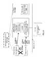
- FIG. 1is a block diagram illustrating one embodiment of a system.
- FIG. 2is a block diagram illustrating aspects of the operation of a primary connection failover driver (CFD) and a shadow CFD during a communication from a primary server to a client, according to one embodiment.
- CFDprimary connection failover driver
- FIG. 3is a block diagram illustrating aspects of the operation of a client, a primary CFD and a shadow CFD during a communication from the client to a primary server, according to one embodiment.
- FIG. 4is a block diagram illustrating aspects of operations that may be performed at a shadow server in response to a detection of a failure, according to one embodiment.
- FIG. 5is a block diagram illustrating a traditional networking software stack at a server, according to one embodiment.
- FIG. 6is a block diagram illustrating an embodiment where a primary CFD is included within a networking software stack at a layer between a network/Internet layer and a NIC driver layer.
- FIG. 7is a block diagram illustrating an embodiment where the primary CFD is included within a networking software stack at a layer between a transport layer and a network/Internet layer.
- FIG. 8is a block diagram illustrating various constituent modules that may be included within a CFD, according to one embodiment.
- FIG. 9is a flow diagram illustrating aspects of the operation of a primary server, a shadow server and a client during transmission of a message packet directed at the client from the primary server, according to one embodiment.
- FIG. 10is a flow diagram illustrating aspects of the operation of a primary server, a shadow server and a client, related to the transmission and acknowledgment of a client message packet directed at the primary server from the client, according to one embodiment.
- FIG. 11is a flow diagram illustrating further aspects of the operation of a shadow server and a client during transmission and acknowledgment of a client message packet directed at a primary server from the client, according to one embodiment.
- FIG. 12is a block diagram illustrating aspects of the operation of a log manager module of a shadow CFD according to one embodiment.
- FIG. 13is a flow diagram illustrating aspects of the operation of a shadow server in response to a failure, according to one embodiment.
- FIG. 14is a block diagram illustrating an embodiment where each server of a plurality of servers is configured to have access to a shared application state area.
- FIG. 15is a block diagram illustrating constituent elements of a primary server, according to one embodiment.
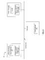
- FIG. 1is a block diagram illustrating a system 100 according to one embodiment.
- system 100includes a primary server 110 , a shadow server 130 , and a client 140 coupled by a network 160 .
- Primary server 110includes a server application 115 and a primary connection failover driver 120 A.
- the term “connection failover driver”may be abbreviated hereinafter as “CFD”.
- Shadow server 130includes a shadow CFD 120 B with access to a log 170 .
- Primary server 110 and client 140may be configured to cooperate to establish a network connection, for example using a reliable, connection-oriented networking protocol such as the Transmission Control Protocol (TCP).
- TCPTransmission Control Protocol
- a client application 145may be configured to use the network connection for communication with server application 115 over network 160 in order to obtain one or more services supported by server application 115 .
- server application 115may be configured to generate a message packet targeted for transmission over the network connection to client application 145 at client 140 .
- Primary CFD 120 Amay be configured to intercept the message packet and redirect it to the shadow server 130 .
- Shadow CFD 120 Bmay be configured to receive the redirected message packet, copy its contents to log 170 , and forward the message packet to the client 140 .
- the forwarded message packetmay appear to have been sent directly from the primary server in some embodiments; e.g., the client 140 may be unaware of the redirection of the packet from the primary server, and the forwarding of the message packet by shadow server 130 .
- no configuration or software changesmay be required at the client 140 to support the redirection and forwarding of message packets, or for saving the contents of the message packets in the log 170 . Further details of the functions provided by primary CFD 120 A and shadow CFD 120 B during communications in both directions between primary server 110 and client 140 , and in response to failures at primary server 110 , are provided below.
- Server application 115may be any type of application configured to transmit data over a network.
- server application 115may be configured to provide services according to a client-server paradigm to one or more client applications 145 , while in other embodiments, server application 115 may be configured to transmit data over network 160 to one or more peer applications in a peer-to-peer architecture.
- server application 115may be a network management application, configured to monitor the state of numerous networking devices such as switches, routers, and the like, and to provide periodic or on-demand state updates to one or more client applications 145 .
- the network management server application 115may be responsible for monitoring networking devices within a single campus, or in a more distributed environment such as a multi-campus network or across multiple data centers physically located in multiple cities or multiple countries. Its client applications 145 may also be either centrally located or geographically distributed. In another embodiment, server application 115 may be a distributed multimedia server or other content server configured to provide client applications 145 with content such as audio and/or video files, or a server configured to provide Voice Over IP (VOIP) services such as long-distance or local telephone services. In some embodiments, server application 115 may be configured to provide equity trading or other financial or banking-related services.
- VOIPVoice Over IP
- server application 115may be an application server (such as a Jave 2 Enterprise Edition (J2EE) server) configured to provide services for a number of higher-level applications such as content subscription services, ticketing services, etc., that may be deployed at the application server, and/or may provide middleware services allowing client applications 145 to access data managed at back-end database servers.
- Server application 115may provide cluster management services in some embodiments, for example to help manage a number of other servers configured as a cluster. It is noted that the technique of redirecting a message packet to a shadow server, and the shadow server forwarding the message packet to a destination, may be used for client-to-server communications in some embodiments, as well as, or instead of, being used for server-to-client communications. In addition, in some embodiments, the technique may also be used for communications between peer applications (e.g., in a peer-to-peer architecture rather than a client-server architecture).
- J2EEJave 2 Enterprise Edition
- Client application 145may be any application configured to receive data from another application, such as server application 115 , over a network 160 .
- a client application 145may include a network management client application providing status on network devices to one or more users via a graphical user interface (GUI), an audio or video playback application, a VOIP subscriber application, etc.
- GUIgraphical user interface
- a primary server 110may be configured to concurrently support hundreds or thousand of clients 140 .
- Client applications 145 accessing a single server application 115may be executed at widely distributed clients 140 .
- Data center administrators or IT administratorsmay have some control over the server-side operating environment (e.g., hardware and software resources and configurations in use at the primary server 110 and at the shadow server 130 ) in some embodiments, but may have limited or no control on client-side operating environments.
- server-side operating environmente.g., hardware and software resources and configurations in use at the primary server 110 and at the shadow server 130
- client-side operating environmentse.g., hardware and software resources and configurations in use at the primary server 110 and at the shadow server 130
- Network 160may be implemented using any of a number of different hardware and software technologies in different embodiments.
- at least a portion of network 160may be a Local Area Network (LAN), which may be implemented using any desired copper-based networking links such as various versions of Ethernet and/or optical fiber-based networking hardware.
- LANLocal Area Network
- primary server 110 and shadow server 130may be configured with networking addresses within a single subnet, e.g., within a portion of a networking address space defined by a subnet address and a subnet mask, to simplify routing of messages between primary server 110 and shadow server 130 .
- network 160may be a Metropolitan Area Network (MAN), a Wide Area Network (WAN), or may include links of a distributed network such as the Internet.
- network 160may include one or more wireless links.
- Any desired reliable, connection-oriented network protocolsuch as TCP or SCTP (Stream Control Transmission Protocol) may be utilized for the network connection between primary server 110 and client 140 .
- a logical communicationsuch as a file transfer, between two endpoints (such as a first network socket at a sender and a second network socket at the recipient) of a connection established according to such a protocol may consist of an ordered sequence of message packets.
- Message packetsmay be sent in either direction over the connection, and acknowledgments for received message packets may be sent by the recipient to the sender, e.g., piggybacked or included within other message packets or as separate acknowledgment packets.
- a technique called “positive acknowledgment with retransmission”may be used to ensure reliable transmission in both directions in accordance with the reliable network protocol.
- positive acknowledgment with retransmissionwhen a recipient receives a packet, the recipient sends an acknowledgment message to the sender.
- the senderkeeps a record of each packet it sends and waits for an acknowledgment before sending the next packet.
- the senderalso starts a timer when it sends a packet and retransmits the packet if the timer expires before an acknowledgment arrives.
- primary CFD 120 A and shadow CFD 120 Bmay be configured to utilize features of a “positive acknowledgment with retransmission” technique that may be in use for the network connection between primary server 110 and client 140 , to also respond to loss or delay of packets redirected from the primary server 110 to the shadow server 130 .
- primary CFD 120 A and shadow CFD 120 Bmay each be implemented as a software layer or module configured to interact with an existing layered networking software stack within an operating system in use at primary server 110 and/or shadow server 130 . Further details on the interactions between the CFDs 120 A and 120 B, and the interactions of the CFDs and the networking software stacks in use at primary server 110 and shadow server 130 , are provided below for various embodiments.
- Log 170may be implemented using any of a number of different technologies in different embodiments. For example, in one embodiment, log 170 may be maintained within volatile storage such as any desired form of magnetic random access memory (RAM), while in other embodiments, log 170 may be implemented using persistent storage or in a combination of volatile and persistent storage.
- volatile storagesuch as any desired form of magnetic random access memory (RAM)
- log 170may be implemented using persistent storage or in a combination of volatile and persistent storage.
- FIG. 2is a block diagram illustrating aspects of the operation of primary CFD 120 A and shadow CFD 120 B during a communication from primary server 110 to client 140 , according to one embodiment.
- Server application 115may be configured to generate a message packet targeted for transmission to the client 140 , as indicated by the arrow labeled “ 1 ” in FIG. 2 .
- the message packetmay be generated, for example, in response to an earlier request received at server application 115 from client application 145 , or may be part of a communication originated at server application 115 without an explicit request having been received from client application 145 .
- the message packetmay be intended for transmission over the network connection previously established between the primary server 110 and client 140 , and may be formatted in accordance with the network protocol used for the established connection.
- the message packetmay include one or more header regions containing control information, and a body or payload region including the actual data to be sent to the client 140 .
- the header regionsmay include, for example, destination addressing information formatted in accordance with the network protocol in use for the connection, sequence numbers and/or acknowledgement numbers, window sizes, checksum values, header and data lengths, etc.
- each layer within a networking software stackmay add (e.g., as a prefix) its own header region containing control information intended for use at a corresponding layer at the recipient. Further details on various layers that may be included within a networking software stack are provided below, in conjunction with the descriptions of FIG. 5 , FIG. 6 and FIG. 7 .
- Primary CFD 120 Amay be configured to intercept the message packet before it is transmitted over the network 160 to client 140 , and to redirect the message packet to shadow server 130 , as indicated by the arrow labeled “ 2 ” in FIG. 2 .
- primary CFD 120 Amay be configured to detect that a given message packet is a candidate for redirection based on an encoding that may have been included within the message packet by server application 115 or by an intermediate software layer between server application 115 and primary CFD 120 A.
- configuration parameterssuch as host and/or port numbers, which may for example be specified in a configuration file, may be used to specify the set of message packets that are candidates for redirection: e.g., all messages sent from a specified (host, port) combination may be designated for redirection.
- Primary CFD 120 Amay be configured to modify one or more destination indicators (such as a destination address in a network link layer header of the message packet) in order to redirect the message packet.
- primary CFD 120 Amay also be configured to modify one or more additional fields of a header within the message packet (such as a protocol identifier) to indicate (e.g., to a recipient CFD such as shadow CFD 120 B) that the message packet is being redirected.
- the message packetAfter the message packet has been modified for redirection, it may be physically transmitted on the network 160 (e.g., by a network interface card (NIC) driver), and may be received at shadow server 130 .
- NICnetwork interface card
- a NIC drivermay be configured to read the contents of the message packet from the network 160 , and to provide the contents to other software layers of the networking software stack in use at shadow server 130 .
- Shadow CFD 120 Bmay be configured to receive the message packet, e.g., from the NIC driver, and copy the contents of the message packet into the log 170 , as indicated by the arrow labeled “ 3 ” in FIG. 2 . After the contents of the message packet have been copied, shadow CFD 120 B may be configured to forward the message packet to the client 140 , as indicated by the arrow labeled “ 4 ” in FIG. 2 .
- the redirection by shadow CFD 120 Bmay include undoing the changes that may have been performed on the message packet by primary CFD 120 A in some embodiments: e.g., by re-setting a destination address to that of the client.
- shadow CFD 120 Bmay also be configured to reset or modify an encoding (such as a network protocol number within a header) that was earlier used by primary CFD 120 A to identify the message packet as a redirected message packet, e.g., to a value that may be typically set for the encoding in accordance with the protocol used for the network connection established between the primary server 110 and the client 140 .
- neither shadow CFD 120 B, nor any other layer of networking software at shadow server 130may be configured to send an acknowledgment to primary server 110 indicating that the redirected message packet has been received at shadow server 130 . That is, the redirection of the message packet to shadow server 130 may be performed in accordance with a protocol that does not require an acknowledgment from the shadow server of a reception of the message packet.
- an existing connectionless, potentially unreliable network protocolsuch as User Datagram Protocol (UDP) may be used for the redirected message packet.
- UDPUser Datagram Protocol
- a custom protocolfor example at the data link layer of a networking software stack, may be used instead.
- the redirected message packetmay be transmitted or tunneled to the shadow server according to a reliable protocol (e.g., contents of the message packet may be included or encapsulated within the body of a packet formatted according to a reliable protocol).
- shadow CFD 120 Bmay be configured not to send any acknowledgment of the reception of the redirected package to primary server 110
- another layer of a networking software stack at shadow server 130such as a transport layer
- shadow CFD 120 Bmay be configured to return the message packet header (or headers) to the state the header (or headers) would be in, had the message packet not been redirected by the primary CFD 120 A. Also, neither primary CFD 120 A nor shadow CFD 120 B may be configured to modify the contents of the body of the message packet. Consequently, when client 140 receives the message packet forwarded by the shadow server 130 , the message may appear to have been sent directly from the primary server 110 . Thus, during normal operation, the client 140 may not be made aware of the redirection of the message packet, or even of the existence and functionality of the shadow server 130 B. One or more layers of a networking software stack in use at client 140 may transfer the message packet to client application 145 .
- shadow CFD 120 Bmay ensure that a record of the message traffic from the primary server 110 to the client 140 is maintained at shadow server 130 .
- shadow server 130may also be configured to maintain a similar record for message traffic from the client 140 to primary server 110 , as described in conjunction with the description of FIG. 3 below.
- the contents of the message packets saved in log 170may include connection state information such as protocol-specific sequence numbers, acknowledgment numbers, window sizes, and the like, such a record of message traffic may later be used to recover connection state in the event of a failure at primary server 110 , as described in further detail below.
- primary server 110may be configured to proceed to other tasks as soon as the message packet has been transmitted by primary CFD 120 A, without waiting for any synchronous responses to the redirected message from shadow server 130 .
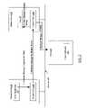
- FIG. 3is a block diagram illustrating aspects of the operation of client 140 , primary CFD 120 A and shadow CFD 120 B during a communication from client 140 to primary server 110 , according to one embodiment.
- the client application 145may generate a client message packet for transmission to the primary server application 115 , e.g., in response to an earlier message received from the primary server 110 as described above.
- the client message packetmay include data being sent from the client application 145 to the server application 115 , may consist of an acknowledgment to an earlier server-generated message, or may include data as well as one or more acknowledgments.
- a native or standard networking software stackmay be used at client 140 without modification, e.g., without the addition of a connection failover driver (CFD.
- the client message packetmay be sent over network to the primary server 110 in accordance with the protocol in use for the client-server connection established earlier between the client 140 and the primary server 110 , as indicated by the arrow labeled “ 1 ” in FIG. 3 .
- the client message packetmay be transmitted to primary server 110 without any header modification or redirection.
- the client message packetmay be received at primary server 110 , e.g., by a NIC driver, and provided to other layers (such as primary CFD 120 A) of the networking software stack at the primary server 110 .
- Primary CFD 120 Amay be configured to transmit a copy of the client message packet to the shadow server 130 , as indicated by the arrow labeled “ 2 ” in FIG. 3 , and to the provide the client message packet to other layers of the networking software stack for eventual delivery to server application 115 , as indicated by the arrow labeled “ 3 ”.
- the transmission of the copy of the client message packet to shadow server 130may be asynchronous with respect to the delivery of the client message to the remaining layers of the networking software stack and server application 115 .
- one or more operations corresponding to the arrow labeled “ 2 ” of FIG. 3may be performed in parallel with, or earlier than, one or more operations corresponding to the arrow labeled “ 3 ”.
- the shadow CFD 120 Bmay be configured to copy the contents of the client message packet in log 170 , as shown by the arrow labeled “ 4 ” in FIG. 3 .
- no acknowledgment of the receipt of the client message packetmay be sent from shadow server 130 to primary server 110 , and no such acknowledgment may be expected at primary server 110 .
- the copy of the client message packetmay also be sent to the shadow server 130 according to a protocol that does not require an acknowledgment in some embodiments, such as a connectionless, potentially unreliable, protocol like UDP.
- a protocol that does not require an acknowledgmentsuch as a connectionless, potentially unreliable, protocol like UDP.
- the same network endpoint or socket that was used for the redirected message packetmay be used for the copy of the client message packet.
- shadow CFD 120 Bmay be configured to copy the contents of the client message packet to log 170 in order to maintain a record of the state of the connection and the message traffic in both directions between client 140 and primary server 110 . Connection state information maintained in log 170 may later be used for connection re-establishment in the event of a failure, as described below in further detail.
- shadow CFD 120 Bmay be configured to simulate the behavior of client application 145 by re-sending data and/or control messages (whose contents may be derived from log 170 ) sent earlier to the server application 115 from the client application.
- shadow CFD 120 Bmay be configured to simulate the behavior of server application 115 by sending message packets with appropriate sequence numbers, acknowledgment numbers and/or message data (also derived from log 170 ) to client application 145 .
- an acknowledgmentmay be generated at primary server 110 for transmission to the client 140 , e.g., in accordance with the connection-oriented reliable network protocol in use for the connection established between client 140 and primary server 110 .
- the acknowledgmentmay be prepared for transmission to client 140 either as part of a message packet, or may be sent as a separate acknowledgment packet.
- primary CFD 120 Amay be configured to intercept the message packet described in FIG. 2
- primary CFD 120 Amay also be configured to intercept the packet containing the acknowledgment, and redirect it to shadow server 130 , as shown by the arrow labeled “ 5 ” in FIG. 3 .
- Similar techniquessuch as a modification of destination address, may be used by primary CFD 120 A for the redirection of the acknowledgment packet as were used for the redirection of the message packet described in conjunction with the description of FIG. 2 above.
- no acknowledgmentmay be expected by primary server 110 to a receipt of the redirected acknowledgment packet at shadow server 130 in some embodiments, and shadow server 130 may be configured not to send any such acknowledgment in such embodiments.
- the copy of the client message packet and/or the redirected acknowledgment packetmay be sent from primary server 110 to shadow server 130 in accordance with a reliable protocol.
- shadow CFD 120 Bmay be configured to copy contents of the packet containing the acknowledgment to the log 170 as well, as indicated by the arrow labeled “ 6 ” in FIG. 3 .
- the client 140may expect to receive the acknowledgment prepared at the primary server 110 .
- shadow CFD 120 Bmay forward the packet containing the acknowledgment to client 140 , as indicated by the arrow labeled “ 7 ” in FIG. 3 .
- shadow CFD 120 Bmay be configured to ensure that an acknowledgment is received at client 140 only if the corresponding client message (i.e., the client message in response to which the acknowledgment was prepared) has been recorded at log 170 .
- forwarding techniques similar to those described above in conjunction with the description of FIG. 2(such as restoring the initial destination address and/or a protocol number that may have been modified by primary CFD 120 A) may be used by shadow CFD 120 B.
- the forwarded acknowledgmentmay appear to the client 140 as though it were sent directly from primary server 110 .
- shadow CFD 120 Bmay be configured to maintain a record of message and acknowledgment traffic in both directions between primary server 110 and shadow server 140 in log 170 in some embodiments.
- Messages generated at client 140may be transmitted undisturbed, i.e., without modification or redirection, to primary server 110 .
- Messages generated at primary server 110may experience a small delay due to the redirection, logging and forwarding through shadow server 130 A.
- the lack of a requirement for acknowledgments from shadow server 130 to primary server 110may allow throughput for server-to-client message traffic to be only minimally impacted in some embodiments, and may also minimize the network-related processing overhead (for example, relative to the use of a protocol requiring explicit or even asynchronous acknowledgments).
- optimizing techniquessuch as maintaining log 170 in a memory allowing efficient access, and by maintaining shadow server 130 in close proximity to primary server 110 (e.g., by ensuring that a minimal number of network hops are required for data to be transferred between primary server 110 and shadow server 130 ), the delay experienced in redirecting, logging and forwarding messages from primary server 110 to client 140 may be minimized.
- Client message copies or redirected messages or acknowledgments that may be lost due to the unreliable nature of the protocolmay result in a temporary throttling of the message flow between the primary server 110 and the client 140 , and/or in a few extra retransmissions, e.g., due to a “positive acknowledgment with retransmission” technique that may be in use for the network connection between the client 140 and primary server 110 .
- shadow CFD 120 Bmay not forward the acknowledgment corresponding to P 2 to client 140 (as noted above, before forwarding an packet containing an acknowledgment for a client message packet, shadow CFD 120 B may be configured to verify that the client message packet has been received and/or written to log 170 ).
- client 140may eventually retransmit P 2 in accordance with the reliable network protocol. Finally, if a redirected acknowledgment packet P 3 corresponding to a client message packet P 2 is lost or dropped before it reaches shadow CFD 120 B, shadow CFD 120 B may also not forward P 3 to client 140 , once again causing an eventual retransmission of P 2 , which would in turn cause a regeneration and redirection of another acknowledgment packet at primary server 110 .
- shadow CFD 120 Bmay be configured to utilize features of the reliable network protocol established between client 140 and primary server 110 (e.g., the feature of positive acknowledgment with retransmission) to manage potential loss of data due to unreliable transmissions between primary server 110 and shadow server 130 .
- a connectionless or potentially unreliable protocol in use between primary server 110 and shadow server 130may also result in duplicated or out-of-order packets in some embodiments.
- Shadow CFD 120 Bmay be configured to simply ignore duplicated packets (e.g., if the contents of a newly-received packet are already in log 170 , shadow CFD 120 B may discard the newly-received packet).
- Out-of-order packetsmay be handled gracefully by shadow CFD 120 B using sequence number information that may be contained in the packets in some embodiments (e.g., shadow CFD 120 B may be configured to store redirected packets that are received out of order within log 170 , but to only forward them to client 140 in sequence). In other embodiments, shadow CFD 120 B may be configured to drop or ignore out-of-order packets received from primary server 110 , which may result in eventual retransmissions in accordance with the reliable network protocol.
- shadow CFD 120 Bwhen a redirected acknowledgment packet is received at shadow server 130 , and shadow CFD 120 B detects that the copy of the corresponding client message packet has not yet been received at shadow server 130 , shadow CFD 120 B may be configured to send a notification to primary CFD 120 A indicating that the copy of the client message packet has not been received. In some implementations, shadow CFD 120 B may be configured to send such a notification to primary CFD 120 A after a configurable time interval has passed since the redirected acknowledgment packet was received. In response to the notification, in some embodiments, primary CFD 120 A may be configured to resend the copy of the client message packet.
- shadow CFD 120 Bmay be configured to actively ensure that message and acknowledgment packets flow efficiently and smoothly between the primary server 110 and the client, instead of relying on positive acknowledgment with retransmission as described above to throttle acknowledgments and eventually cause retransmissions.
- shadow CFD 120 Bmay be configured to notify the primary CFD 120 A when it detects a missing redirected acknowledgment packet; e.g., when a copy of a client message packet is received at shadow server 130 , but no corresponding redirected acknowledgment packet is received at the shadow server within a configurable time interval.
- Such notifications of expected redirected acknowledgment packets and/or expected copies of client message packetsmay be sent to primary server 110 over a reliable connection (e.g., a connection used for exchanging control information between primary CFD 120 A and shadow CFD 120 B) in some embodiments, and via an unreliable protocol in other embodiments.
- a reliable connectione.g., a connection used for exchanging control information between primary CFD 120 A and shadow CFD 120 B
- an unreliable protocolin other embodiments.
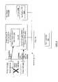
- FIG. 4is a block diagram illustrating aspects of operations that may be performed at shadow server 130 in response to a detection of a failure, according to one embodiment.
- Any of a number of different types of failuresmay affect communication over a network connection established between a primary server 110 and a client 140 .
- Such failuresmay be caused, for example, by one or more failures of hardware and/or software components at either end of the connection, or by one or more hardware or software failures in the network connecting the primary server 110 to the client, or due to excessive congestion in the network, etc. While the operations shown in FIG. 4 may be performed upon a detection of a failure at the primary server 110 , similar operations may also be performed in response to other types of failures in other embodiments.
- each CFDsuch as primary CFD 120 A or shadow CFD 120 B may include a membership module configured to maintain information on the availability status of other CFDs.
- shadow CFD 120 Bmay, for example, be configured to periodically exchange heartbeat or “I-am-alive” messages with the primary CFD 120 A, and to infer that primary server 110 has failed if one or more heartbeat messages are not received from primary CFD 120 A within a specified time period. Heartbeat messages and other control information may be exchanged between CFDs over a reliable connection in some embodiments.
- control informationmay be transferred between primary CFD 120 A and shadow CFD 120 B using a reliable, connection-oriented network protocol that requires messages to be acknowledged, while redirected server-to-client message and acknowledgment packets may be transferred using a protocol that does not require acknowledgments.
- Other techniques for failure detectionmay be used in some embodiments, such as integration with a cluster manager, external heartbeat management software, and the like.
- shadow CFD 120 Bmay be configured to use the connection state information to take over the network connections previously established between primary server 110 and client 140 , as illustrated by the arrow labeled “ 1 ” in FIG. 4 .
- a failover version 115 A of server application 115may be configured to provide the services previously provided by the server application from primary server 110 , as indicated by the arrow labeled “ 2 ” in FIG. 4 .
- Shadow CFD 120 Bmay be configured to maintain the connections that had been established between the primary server 110 A and the client 140 , in such a way that the failure of the primary server 110 is not detected by client 140 , and to transparently re-establish communication between the failover version 115 A of the application and the client 140 .
- Shadow CFD 120 Bmay be configured to use information previously saved in log 170 (such as sequence numbers, acknowledgment numbers, window sizes, etc.), for example to simulate the client to the failover application version 115 A and to simulate the application to the client 140 A, during failover and recovery.
- failover version 115 A of the applicationmay be assigned one or more new connection endpoints (e.g., sockets) for use in communicating with the client 140 .
- shadow CFD 120 Bmay be configured to provide network address translation (NAT) to translate a network address (e.g., a port number) and/or sequence numbers (e.g., TCP or other transport level sequence numbers) associated with newly assigned endpoints to match the network address and/or sequence numbers previously saved in log 170 .
- NATnetwork address translation
- the translationmay mask out changes to the network address and/or sequence numbers, so that the failover of application 115 may be transparent to client 140 in such embodiments: e.g., client 140 may continue its communication with the application as though application failover had not occurred.
- server application 115may be configured to maintain application state information in a persistent storage area accessible from shadow server 130 , such as a distributed shared memory or another shared storage device, so that application state can be recovered by the failover version II SA of the application. Further details about different types of application failover (such as stateless and stateful failover), and the operations that may be performed by shadow CFD 120 B during failover, are provided below in conjunction with the descriptions of FIG. 13 and FIG. 14 .
- a new shadow server 130 B including a new log 170 Bmay be configured (e.g., as part of the failover of primary CFD 120 A to shadow CFD 120 B) to provide the logging and forwarding functions being performed by shadow server 130 prior to the failure.
- failover version 115 A of application 115 and shadow CFD 120 Bmay be configured to fail back to primary server 110 (i.e., to again provide application services and primary CFD services from primary server 110 ).
- Shadow server 130 A, failover application version 115 A and shadow CFD 120 Bmay be configured for fail back in this manner even if no additional failure (i.e., no failure beyond the failure that lead to the failover) is detected in some embodiments, and may be configured for fail back only if a failure is detected at shadow server 130 and/or in a new shadow server 130 B in other embodiments.
- a fail back techniquemay be implemented, for example, in an environment where primary server 110 is configured with hardware (e.g., faster processors, more memory, etc.) capable of higher overall performance than hardware at shadow server 130 , so that transferring responsibilities for the server application back to the primary server after it recovers may result in a better quality of service than would be possible if the shadow server were used for the server application for an extended period.
- hardwaree.g., faster processors, more memory, etc.
- a client CFDmay be incorporated at client 140 , and may be configured to redirect client-to-server messages to an additional shadow server (or the same shadow server used by primary server 110 ) for eventual forwarding to the primary server 110 .
- the techniques of redirecting a message packet to a shadow server, and the shadow server forwarding the message packet to a destinationmay be used for communication in either direction between a client and a primary server, or between peer applications.
- FIG. 5is a block diagram illustrating a traditional networking software stack 525 at a server 510 according to one embodiment.
- Server 510may represent any server configured to support network communication, such as a primary server 110 or a shadow server 130 described earlier. It is noted that traditional networking stack 525 or an equivalent may also be implemented at client 140 in some embodiments.
- FIG. 6 and FIG. 7are block diagrams illustrating examples of the manner in which a CFD may interact with various layers of a networking software stack at primary server 110 and shadow server 130 in different embodiments. As shown in FIG.
- a traditional networking stack 525may include a transport layer 530 , a “networking” or “Internet” layer 540 , and a network interface card (NIC) driver layer 550 .
- the networking stack 525may typically form part of an operating system, such as various versions of SolarisTM from Sun Microsystems, Linux, and various versions of WindowsTM from Microsoft Corporation.
- an operating systemsuch as various versions of SolarisTM from Sun Microsystems, Linux, and various versions of WindowsTM from Microsoft Corporation.
- different operating systemsmay include networking software stacks that provide similar functions at corresponding layers: e.g., a transport layer of a networking software stack in a SolarisTM operating system may provide similar functions to a transport layer in a WindowsTM operating system.
- the layers of the networking software stack 525may provide different functions in accordance with the specific protocol or protocols being supported at each layer.
- the transport layer 530may implement TCP, and the network/Internet layer 540 may support IP.
- the transport layer 530may implement reliable delivery of packets to applications such as server application 115 , e.g., using positive acknowledgment with retransmission as described above.
- the transport layer 530may also allow multiple server applications 115 within a given server 510 to communicate concurrently, e.g., it may demultiplex incoming traffic among the multiple server applications.
- the transport layer 530may be configured to implement a state machine for each connection established between two endpoints (e.g., a sender and a recipient), to manage congestion control, timeouts, retransmissions, etc.
- a server application 115may be configured to interact with the transport layer 530 , for example using one or more system calls such as socket( ), bind( ), listen( ), accept( ), connect( ), read( ), write( ), close( ), and the like.
- the transport layer 530may add a header containing transport-level control information to a message packet body, including one or more of the following: source and destination information, a sequence number, an acknowledgment number, a window size indicating a maximum number of unacknowledged messages that may be outstanding, a checksum, an “urgent” pointer, various advanced options, etc.
- the headermay be examined and used at a corresponding transport layer 530 at the recipient of the message packet.
- Various other functionsmay also be performed at transport layer 530 .
- the network or Internet layer 540may be configured to handle communication from one machine or host to another. It may accept a request to send a packet from the transport layer 530 , include the packet within a basic transfer unit that may be termed a datagram, generate a header for the datagram containing network/Internet layer control information, and use a routing algorithm to designate a next host to which the datagram is to be sent. The next host may be the destination of the datagram, or may be a router, a gateway, or some other intermediate device or host.
- the network/Internet layer 540may be configured to pass the datagram for transmission to NIC driver layer 550 . Incoming datagrams may also be handled (e.g., checked for validity, processed locally or forwarded) by the network/Internet layer 540 . For datagrams addressed to the local host, the network/Internet layer may delete the datagram header and choose the appropriate transport protocol to which the remaining contents of the datagram should be forwarded.
- Various additional functionsmay also be supported at the network/Internet layer 540 .
- the NIC driver 550may be responsible for accepting outgoing Internet layer datagrams and transmitting them over a specific NIC 560 , such as an Ethernet card, using a data link layer protocol.
- NIC driver 550may be configured to add its own header, for example containing a data link layer recipient address (such as a Media Access Control or MAC address in the case of Ethernet) to the datagram.
- a data link layer recipient addresssuch as a Media Access Control or MAC address in the case of Ethernet
- network/Internet layer 540may be configured to select an appropriate NIC driver from the available NIC drivers in such embodiments.
- a NIC driver layer 550may also be responsible for receiving incoming datagrams received at a NIC 560 in accordance with a data link layer protocol, and passing them on to a next higher-level networking software layer such as the network/Internet layer 540 .
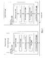
- FIG. 6is a block diagram illustrating an embodiment where the primary connection failover driver (CFD) 120 A is included within a networking software stack 520 A at a layer between a network/Internet layer 540 A and a NIC driver layer 550 A.
- the shadow CFD 120 Bis included within a networking software stack 520 B at a layer between a network/Internet layer 540 B and a NIC driver layer 550 B at shadow server 130 .
- FIG. 7is a block diagram illustrating another embodiment, where the primary CFD 120 A is included within a networking software stack 520 A at a layer between a transport layer 530 A and a network/Internet layer 540 A, and the shadow CFD 120 A is included within a networking software stack 520 B between a transport layer 530 B and a network/Internet layer 540 B.
- a CFD 120i.e., CFD 120 A or CFD 120 B
- a transport layer 530i.e., CFD 530 A or CFD 530 B
- the specific layer at which a CFD 120 is included within a networking software stack 520may affect the specific headers that may be modified or inspected by the CFD 120 in order to implement the redirection/forwarding operations described earlier.
- CFD 120 Amay be configured to modify information contained within a data link layer header (such as an Ethernet MAC address) in order to redirect an outgoing message packet to shadow server 130 , and to leave network/Internet layer and transport layer headers unmodified.
- CFD 120 Amay be configured to modify information contained within a network/Internet layer header, and to leave the transport layer header unmodified.
- the CFDs 120may be activated dynamically, without requiring a modification, recompilation or re-linking of existing code in remaining layers of the corresponding network software stacks 520 .
- the operating system in use at primary server 110may be configurable to dynamically branch to code within the CFD 120 A when any of a number of functions is invoked within a neighboring layer of the networking software stack.
- the operating systemmay also allow dynamic reconfiguration, deactivation and/or disablement of the CFDs 120 . The enablement and/or disablement of a CFD 120 may thus not require modification of the functionality provided by other layers of the corresponding networking software stack 520 .
- FIG. 8is a block diagram illustrating various constituent modules that may be included within a connection failover driver 120 according to one embodiment. It is noted that while a given CFD 120 may be configured to provide different functions depending, for example, on whether the given CFD is executing at a primary server 110 or at a shadow server 130 at a given time, in general the same modules may be included within each CFD 120 . Different functions supported by the constituent modules of the CFD may be activated as the role of the CFD changes, e.g., from being a shadow CFD 120 B to being a primary CFD 120 A after a failover.
- a CFD 120may include a membership module 121 A, a connection protection module 121 B, a virtual connection simulation module 121 C, and a log manager module 121 D in the depicted embodiment.
- Membership module 121 Amay be configured to implement heartbeat message generation and monitoring on a collection of servers such as primary server 110 , shadow server 130 , as well as additional servers that may be configured as future or potential candidates for failover.
- a membership module 121 A at each participating servermay be configured to generate heartbeat messages targeted at each other participating servers, and to keep track of heartbeat messages received from each of the other participating servers.
- the membership module 121 Amay be configured to (either alone or in cooperation with other membership modules at other servers) infer that the given server has failed, and to initiate desired failover functions in response to the detection.
- the membership module 121 Amay support the joining of new servers wishing to cooperate with the existing set of servers in connection and/or application failover, the departure of a server from the group, and other similar group membership functions.
- a membership module 121 Amay be configured to cooperate with another software module such as a cluster manager to track the availability or failure of other servers that may be configured to participate in connection and/or application failover.
- Connection protection module 121 Bmay be configured to perform a number of functions to maintain a previously established connection (e.g., to prevent a previously established network connection from being closed) upon the occurrence of a failure.
- a connection protection module 121 B in shadow CFD 120 Bmay be configured to take over an IP address associated with the primary server 110 in the event of a failure at primary server 110 . That is, connection protection module 121 B may be configured to start accepting message packets with a destination IP address that was previously the IP address of the primary server 110 , and to start transmitting message packets that include a source IP address that was previously the IP address of the primary server 110 .
- connection protection module 121 Bmay be configured to utilize existing functionality provided, for example, by a cluster manager or by a “Virtual IP” module or modules, to take over the IP address.
- Connection protection module 121 Bmay also be responsible for sending control information to client 140 for a connection that is to be kept open after a failure, for example by sending one or more acknowledgments packets with appropriate sequence numbers, by adjusting a TCP window size, etc., in one embodiment. For example, during a period when a failover version 115 B of the server application is performing recovery operations (e.g., re-issuing messages sent earlier to the client that have not yet been acknowledged), connection protection module 121 B may be configured to send client 140 control information indication that the networking software stack 525 at the client 140 should temporarily stop sending new messages on the connection, thus giving the failover application time to complete recovery operations without having to manage new client requests.
- recovery operationse.g., re-issuing messages sent earlier to the client that have not yet been acknowledged
- Connection protection module 121 Bmay also be configured to modify or adjust sequence numbers and/or acknowledgment numbers within packets transmitted from the shadow server 130 (as it takes over the function of the primary server 110 after a failure) to client 140 in some embodiments, in order to match the values for the sequence numbers and/or acknowledgment numbers that may be expected by the client 140 .
- Connection protection module 121 Bmay be configured to access entries saved in log 170 in order to perform one or more of its functions.
- Virtual connection simulation module 121 Cmay be configured to perform one or more authentication or security related functions, and/or to simulate the behavior of client 140 during a reestablishment of connections between a failover version 115 B of the server application and the client application 145 .
- virtual connection simulation module 121 Cmay be configured to authenticate the failover version 115 B of the server application, to ensure that an unauthorized entity (such as software introduced at shadow server 130 by a virus or as a result of an intrusion) does not take over from the failed server application 115 .
- virtual connection simulation module 121 Cmay simulate the behavior expected of the client application 145 by the failover version 115 B of the server during a connection establishment. For example, if a TCP connection was previously established via an “active open” at the client in one implementation, virtual connection simulation module 121 C may be configured to resend the same packets to the failover version 115 B of the application during connection reestablishment that were earlier sent by the client 140 to the server application 115 during the “active open”. Virtual connection simulation module 121 C may be configured to obtain the packets needed to simulate client behavior from log 170 in some embodiments.
- Log manager module 121 Dmay be configured to save redirected and/or copied message and acknowledgment packets within log 170 in some embodiments.
- other log-related functionssuch as deleting entries from log 170 that may no longer be needed, saving log entries from volatile memory to persistent storage, replaying log entries during failover and connection reestablishment, and/or providing log access to virtual connection simulation module 121 C and connection protection module 121 B, may also be supported by log manager 121 D in various embodiments. Further details about aspects of the operation of a log manager module 121 D in one embodiment are provided below in conjunction with the description of FIG. 12 . It is noted that not all the modules 121 A- 121 D shown in FIG. 8 may be implemented in some embodiments.
- modules 121 A- 121 Dmay be performed by other modules (including modules not shown in FIG. 8 ), or may be omitted in some embodiments. Additional functions, not associated specifically with any of the modules 121 A- 121 D in the foregoing description, may also be performed by a CFD 120 in some embodiments. As noted earlier, the specific functions being performed by a given CFD 120 may vary from time to time in some embodiments, and the functions performed by a primary CFD 120 A at a given point of time may differ from the functions being performed by a shadow CFD 120 B.
- FIG. 9is a flow diagram illustrating aspects of the operation of primary server 110 , shadow server 130 and client 140 during transmission of a message packet directed at client 140 from the primary server 110 , according to one embodiment.
- primary server 110 and client 140may be configured to cooperate to establish a network connection, for example via a reliable network protocol such as TCP.
- the networking software stack at primary servermay generate a next message packet for transmission (block 915 ) to client 140 over the connection.
- Primary CFD 120 Amay be configured to intercept the next message packet, and to redirect it to the shadow server 130 (block 920 ) as described earlier, without expecting any acknowledgment from the shadow server 130 .
- Shadow server 130may not send any acknowledgment to the primary server 110 .
- Shadow CFD 120 Bmay be configured to copy the contents of the next message packet into the log 170 (block 930 ), and to forward the next message packet to client 140 (block 940 ) as described earlier.
- Client 140may receive the forwarded message packet (block 945 ), which may appear to the client to have been sent directly by the primary server.
- FIG. 10is a flow diagram illustrating aspects of the operation of primary server 110 , shadow server 130 and client 140 related to the transmission and acknowledgment of a client message packet directed at primary server 110 from client 140 , according to one embodiment.
- Client 140may be configured to transmit the client message packet to primary server 110 in accordance with the network protocol being used for the connection previously established between client 140 and primary server 110 , as shown in block 1005 of FIG. 10 , e.g., using an unmodified traditional networking software stack 525 at client 140 that does not include a CFD. That is, unlike packets directed at client 140 from primary server 110 , packets directed from client 140 to primary server 110 may not be subject to redirection and/or forwarding by a CFD 120 .
- primary CFD 120 A at primary server 110may be configured to transmit a copy of the client message packet to shadow server 130 (block 1015 ), and to deliver the contents of the client message packet to one or more remaining layers of the networking software stack in use at the primary server 110 and/or to server application 115 .
- the transmission of the copy of the client message packetmay be performed asynchronously in some embodiments, e.g. in order to reduce the performance impact on the delivery of the client message packet to server application 115 .
- No acknowledgmentmay be expected at the primary server 110 for the copy of the client message packet sent to the shadow server 130 .
- shadow CFD 120 B at shadow server 130may be configured to copy the contents of the client message packet in the log (block 1025 ) without sending any response or acknowledgment to the primary server 110 .
- the networking software stack 520 A at the primary server 110may be configured to prepare an acknowledgment for the client message packet (e.g., at a transport layer 530 A such as a TCP layer of the networking software stack) (block 1030 ).
- the acknowledgmentmay be prepared as part of a message packet, or in a separate acknowledgment packet.
- Primary CFD 120 Amay be configured to redirect the packet containing the acknowledgment to the shadow server 130 (block 1035 ), again expecting no acknowledgments from the shadow server 130 in response to the redirection.
- shadow CFD 120 Bmay be configured to save the contents of the redirected packet, including the acknowledgment, in log 170 (block 1045 ) without sending a response to the primary server 110 .
- Shadow CFD 120 Bmay be configured to verify that the client message packet corresponding to the acknowledgment (i.e., the client message packet for which the acknowledgment was generated) has been received at shadow server 130 and/or saved in log 170 (block 1050 ), prior to forwarding the packet containing the acknowledgment to client 140 (block 1055 ).
- shadow CFD 120 Bmay be configured to verify that a sequence number identified in the acknowledgment matches a sequence number for a client message packet saved in the log.
- Client 140may receive the packet containing the acknowledgment (block 1060 ), which may appear to the client to have been sent directly from primary server 110 .
- FIG. 11is a flow diagram illustrating further aspects of the operation of shadow server 130 and client 140 during transmission and acknowledgment of a client message packet directed at primary server 140 from client 140 , according to one embodiment.
- client 140may be configured to transmit a client message packet to primary server 110 over the network connection established between the client and the primary server.
- block 1005 of FIG. 10is repeated in FIG. 11 , and operations performed at the primary server 110 in response to the reception of the client message packet, such as operations illustrated in block 1010 of FIG. 10 , are symbolized in FIG. 11 by a circle labeled “ 1010 ”.
- a layer of networking software stack at client 140may be configured to start a timeout period, based on parameters of the network protocol in use for the network connection, for an acknowledgment corresponding to the client message packet (block 1150 ).
- an acknowledgmentmay be generated for the client message packet and redirected to the shadow server 130 , as described above and as indicated by the circle labeled 1035 (representing the operations corresponding to block 1035 of FIG. 10 ) in FIG. 11 .
- the shadow CFD 120 Bmay be configured to receive a packet containing the acknowledgment and save the contents of the packet in the log 170 (blocks 1040 and 1045 of FIG. 11 , repeated for clarity from FIG. 10 ).
- shadow CFD 120 Bmay be configured to check whether the client message packet has already been received and/or saved in log 170 , prior to forwarding the redirected packet containing the acknowledgment (decision block 1105 ).
- shadow CFD 120 Bmay be configured to forward the acknowledgment to client 140 (block 1055 of FIG. 11 , repeated from FIG. 10 ). If the client message packet has not been received or is not found in the log 170 , shadow CFD 120 B may be configured to start a configurable timeout period during which it expects the copy of the client message packet to be received from primary server 110 A (block 1110 ). Shadow CFD 120 B may then wait for the copy of the client message packet (block 1115 ). If the copy of the client message packet is received before the timeout expires (as detected in decision block 1120 ), the acknowledgment may be forwarded to the client.
- shadow CFD 120 Bmay be configured to notify primary CFD 120 A (block 1130 ) in one embodiment.
- a reliable connectione.g., a TCP connection
- shadow CFD 120 Bmay be configured to notify primary CFD 120 A of a detection of a missing copy of a client message packet (e.g., when a redirected acknowledgment is received for which the associated copy of the client message packet has not been received), and/or to notify primary CFD 120 A of a detection of a missing acknowledgment (e.g., when a copy of a client message packet is received, but no corresponding redirected acknowledgment is received within a specified time interval).
- client 140may be configured to wait for the acknowledgment (block 1155 ). If the acknowledgment is received before the timeout expires (as detected in decision block 1160 ), client 140 may be configured to continue communication with the server application 115 (block 1175 ), for example by generating a new client request or responding to a message received from the primary server 110 . If the client's timeout expires before the acknowledgment is received (as detected in decision block 1165 ), client 140 may retransmit the client message packet in accordance with the network protocol in use for the connection to primary server 110 (block 1170 ). Such a retransmission may lead to further operations at the primary server 110 , similar to those described earlier in response to the original transmission of the client message packet to the primary server 110 .
- the expiration of the client timeout while waiting for an acknowledgmentmay be caused by one or more packets (such as packets containing a copy of the client message packet, or packets containing acknowledgments) being dropped or delayed during transmission over an unreliable network protocol from primary CFD 110 A to shadow CFD 110 B.
- packetssuch as packets containing a copy of the client message packet, or packets containing acknowledgments
- data loss and/or delaymay typically be rare.
- the retransmission of the client message packet in accordance with the network protocol used for the client-to-primary server connectionmay resolve the problem with minimal overhead.
- the timeout used at shadow server 130 while waiting for a copy of the client message packetmay be set at a larger value than the timeout value that may be in use at the client in some embodiments, so that retransmissions from the client may allow the shadow server to avoid having to notify the primary server of missing client message packets.
- FIG. 12is a block diagram illustrating aspects of the operation of a log manager module 121 D of a shadow CFD 120 B according to one embodiment.
- Log manager module 121 Dmay be configured to wait for the next packet from the primary server 110 (block 1205 ), such as a redirected message packet, a redirected acknowledgement packet, or a copy of a client message packet.
- log manager module 121 Dmay be configured to save contents of the packet in a portion of the log maintained in volatile memory (block 1215 ).
- log manager module 121 Dmay be configured to periodically prune the log 170 , i.e., to remove entries that may no longer be useful, such as entries for connections that have been closed. If such log pruning is to be performed (as detected in decision block 1220 ), log manager module 121 D may be configured to select any entries appropriate for removal, and delete such entries from the log if any are selected (block 1225 ).
- log manager module 121 Dmay also be configured to save a subset or all of the entries of log 170 that are maintained in volatile memory to persistent storage (such as disk or non-volatile RAM (NVRAM)). If any entries are to be saved to persistent storage (as detected in decision block 1230 ), log manager module 121 D may be configured to save selected log entries in nonvolatile or persistent storage (block 1235 ), and to again wait for the next packet from the primary server (block 1205 ). As noted above, entries of log 170 may be saved to non-volatile storage asynchronously in one embodiment.
- NVRAMnon-volatile RAM
- all entries in the volatile memory portion of log 170 that have not been prunedmay be saved to persistent storage, while in other embodiments, a criterion such as connection age (i.e., the duration for which a connection has been open), the number of entries currently in the volatile memory, or another criterion may be used to select a subset of entries for saving to nonvolatile storage.
- a criterionsuch as connection age (i.e., the duration for which a connection has been open), the number of entries currently in the volatile memory, or another criterion may be used to select a subset of entries for saving to nonvolatile storage.
- connection agei.e., the duration for which a connection has been open
- another criterionmay be used to select a subset of entries for saving to nonvolatile storage.
- pruning operation described abovemay be performed on both the volatile memory and nonvolatile storage portions of a log 170 in some embodiments, and on either the volatile portion or the persistent portion in other embodiments. Prun
- either the pruning operations, the saving of log entries to persistent storage, or both the pruning and the saving operationsmay be omitted.
- all entries of the log 170may be maintained in non-volatile storage, such as NVRAM, while in another implementation, all log entries may be maintained only within volatile memory.
- FIG. 13is a flow diagram illustrating aspects of the operation of a shadow server 130 in response to a failure, according to one embodiment.
- a failover version 115 B of the server application 115may be started at shadow server 130 in the event of a failure at primary server 110 .
- the failover version 115 B of the applicationmay be configured to re-establish connectivity to client application 145 and to resume providing server application functionality, without closing one or more connections that may have been opened for communication with the client application 145 .
- a given server application 115may be configured for stateless failover or for stateful failover, and the operations performed by the CFD 120 B may differ for the two kinds of failover.
- Any desired failure detection mechanismsuch as a heartbeat mechanism, may be used at the shadow server 130 to detect or infer the failure of the primary (block 1305 ) in the embodiment depicted in FIG. 13 .
- CFD 120 Bmay be configured to take over an IP address previously associated with the primary server 110 and/or specifically associated with server application 115 (block 1310 ). For one or more connections that were open at the time of the failure, CFD 120 B may be configured to send flow control information to the client, e.g., to simulate the presence of a connected server application 115 and/or to reduce or eliminate client-generated traffic while the failover application is brought up and recovery operations performed at the shadow server (block 1315 ).
- CFD 120 Bmay be configured to derive the flow control information (as well as other control information such as appropriate sequence numbers etc.) using connection state information from one or more entries of log 170 . By maintaining or keeping alive connections that were open at the time of the failure, and/or by sending control information to the client 140 as needed, CFD 120 B may be configured to prevent the client from detecting that a failure occurred. CFD 120 B may also be configured to authenticate the server application, e.g., by checking one or more security credentials provided by the failover version 115 B of the server application (block 1320 ). In some embodiments, CFD 120 B may also be configured to select an additional server, such as server 130 B of FIG. 4 , to serve as a new shadow server (block 1325 ), and to establish contact with the selected additional server, e.g., in order to initialize the operations of a CFD 120 at the additional server.
- an additional serversuch as server 130 B of FIG. 4
- Some server applications 115may be configured for stateless recovery. For example, a failover version of a network monitoring server application may only need re-establishment of existing network connections that were open at the time a failure at a primary server 110 occurred, and may not need to repeat message transmissions or recover additional application state. As described below and illustrated in FIG. 13 , CFD 120 B may be configured to automatically reestablish connections for a stateless recovery using connection state information obtained from log 170 , without explicit requests from the application identifying specific connections to be reestablished. Other server applications, which may be termed stateful applications, may be configured to maintain application state transactionally, for example in a shared storage area called a shared application state area (SASA) as illustrated in FIG. 14 .
- SASAshared application state area
- each server of a plurality of servers(servers 110 , 130 , and 130 B) is configured to have access to a SASA 1401 , in which application state information for a server application 115 may be saved.
- Shared application state area 1401may be implemented using any desired storage technology, such as a distributed shared memory (DSM), NVRAM, or using any of a number of disk-based storage devices, such as SAN-connected storage, SCSI-connected disks or disk arrays, etc.
- DSMdistributed shared memory
- NVRAMnon-connected storage
- Entries saved in SASA 1401may indicate committed or completed operations.
- Each entry in SASA 1401may correspond to one or more message packets transmissions and/or acknowledgments that may have been logged in log 170 .
- a failover version 115 B of a stateful server applicationmay be configured to re-establish a specified set of connections, and/or to “replay” one or more entries in a log 170 (i.e., to re-send one or more logged packets to the client 140 , and/or to re-receive one or more logged packets sent by the client 140 ), as described below.
- CFD 120 Bmay be configured to reestablish one or more connections by simulating the operations of a client during the initial connection establishment (block 1335 ).
- Various header fields containing connection statesuch as packet sequence numbers, derived from entries saved in log 170 may be used by CFD 120 B during connection reestablishment and recovery.
- CFD 120 Bmay identify one or more connections to be reestablished, for example using entries in log 170 , without having to receive a request from the failover version 115 B of the server application identifying the connections.
- one or more plugin modulesmay also be optionally implemented at CFD 120 B, for example to simulate the client's role in a client-server handshake protocol (such as a login protocol) that may typically be used when a client actually connects to the server application (block 1340 ).
- a plugin modulemay be developed for any desired server application, and dynamically activated and/or deactivated at the CFD 120 B as needed.
- stateless recoverymay be complete (block 1345 ) in some embodiments. In other embodiments, additional steps not shown in FIG. 13 may be performed to complete stateless recovery.
- CFD 120 Bmay be configured to provide a list of the connections that were open at the time of the failure to the failover version 115 B of the application (block 1350 ).
- the failover version 115 B of the server applicationmay be configured to request such a list, for example using a specific API supported by CFD 120 B, in some embodiments.
- failover version 115 B of the server applicationmay be configured to send one or more requests identifying specific connections to be recovered or reestablished.
- CFD 120 Bmay be configured to simulate the functions of a client during the initial connection establishment for the specified connections (block 1360 ) (similar to the operations performed by CFD 120 B corresponding to block 1335 for stateless recoveries). Connection state information such as sequence numbers may be obtained from entries in log 170 during connection reestablishment and recovery.
- the failover version 115 B of the server applicationmay then be configured to resume operations from a last-checkpointed or last-saved state in some embodiments, e.g., based on entries saved in a SASA 1401 .
- the server applicationmay request a replay or resend of one or more messages transmissions to client 170 , where the contents of the some of the requested messages may have been saved earlier in log 170 (block 1365 ). Other messages being replayed by the server application may not have reached shadow server 130 prior to the failure, and so may not be present in log 170 , or may not have been saved in log 170 for some other reason.
- CFD 120 Bmay be configured to ignore one or more replay requests (if, for example, the requested message had already been sent to the client 140 prior to the failure), and to resend other messages requested by the server application (block 1370 ).
- NATnetwork address translation
- shadow CFD 120 Bmay be performed by shadow CFD 120 B to support transparent application-level recovery of connections during failover.
- address translationmay be provided by shadow CFD 120 B during either stateless or stateful failover in various embodiments.
- failover version 115 A of the applicationmay be assigned one or more new connection endpoints (e.g., sockets) for use in communicating with the client 140 in some embodiments.
- shadow CFD 120 Bmay be configured to provide network address translation (NAT) to translate a network address (e.g., a port number) and/or sequence numbers (TCP or other transport level sequence numbers) associated with newly assigned endpoints to match the network address and/or sequence numbers previously saved in log 170 .
- the translationmay hide or mask changes to the network address and/or sequence numbers, so that the failover of application 115 may be transparent to client 140 in such embodiments: e.g., client 140 may continue communication with the application as though application failover had not occurred.
- Stateful recoverymay be complete after all the message transmission or replay requests have been processed by CFD 120 B (block 1345 ) in some embodiments, while in other embodiments one or more additional steps not shown in FIG. 13 may be performed to complete stateful recovery. It is noted that not all the steps shown in FIG. 13 may be performed for stateful or stateless recovery in some embodiments, and that some of the steps may be performed in a different order than the order shown in FIG. 13 in other embodiments. For example, the selection and establishment of contact with a new shadow server (block 1325 ) may be performed prior to authenticating the failover application (block 1320 ) in some embodiments.
- connection failoversmay be accomplished in a manner transparent to the client, and without any modification of client networking software.
- FIG. 15is a block diagram illustrating constituent elements of a primary server 110 , according to one embodiment.
- primary server 110may comprise one or more processors such as processors 190 A, 190 B, . . . , 190 N (collectively, processors 190 ) coupled to one or more memories such as memory 195 .
- processors 190may be implemented using any desired architecture or chip set, such as the SPARCTM architecture from Sun Microsystems or the x86-compatible architectures from Intel Corporation, Advanced Micro Devices, etc. Part or all of log 170 may be incorporated within memory 195 .
- Program instructions that may be executable to implement the functionality of server application 115 and/or networking software stack 520 Amay be partly or fully resident within a memory 195 at a given point in time.
- Memory 195may be implemented using any appropriate medium such as any of various types of RAM (e.g., DRAM, SDRAM, RDRAM, SRAM, etc.).
- Primary server 110may also include one or more I/O interfaces 156 providing access to one or more persistent storage devices 196 , and one or more network interface cards (NICs) 155 providing access to network 160 .
- NICsnetwork interface cards
- part or all of log 170may be stored within a persistent log area 171 of a storage device 196 , and part or all of the program instructions that may be executable to implement the networking software stack 520 and server application 115 may also be present in a persistent storage device 196 at a given point in time.
- a persistent storage device 196may include any of a number of different types of storage devices, such as individual disks, disk arrays, optical devices such as CD-ROMs, CD-RW drives, DVD-ROMs, DVD-RW drives, flash memory devices, various types of RAM and the like.
- One or more storage devices 196may be directly coupled to primary server 110 in some embodiments (e.g., using the Small Computer Systems Interface (SCSI) protocol), or may be accessible over any desired storage interconnect such as a fiber channel fabric or storage area network (SAN) in other embodiments.
- SCSISmall Computer Systems Interface
- shadow server 130 and any other additional servers used for connection failoversmay also include the features illustrated in FIG. 15 .
- the operating system in use at the primary server 110may differ from the operating system in use at the shadow server 130 and/or the operating system in use at client 140 .
Landscapes
- Engineering & Computer Science (AREA)
- Theoretical Computer Science (AREA)
- Quality & Reliability (AREA)
- Physics & Mathematics (AREA)
- General Engineering & Computer Science (AREA)
- General Physics & Mathematics (AREA)
- Computer Security & Cryptography (AREA)
- Computer Networks & Wireless Communication (AREA)
- Signal Processing (AREA)
- Data Exchanges In Wide-Area Networks (AREA)
- Computer And Data Communications (AREA)
Abstract
Description
Claims (14)
Priority Applications (1)
| Application Number | Priority Date | Filing Date | Title |
|---|---|---|---|
| US11/052,644US7668962B2 (en) | 2005-02-07 | 2005-02-07 | System and method for connection failover using redirection |
Applications Claiming Priority (1)
| Application Number | Priority Date | Filing Date | Title |
|---|---|---|---|
| US11/052,644US7668962B2 (en) | 2005-02-07 | 2005-02-07 | System and method for connection failover using redirection |
Publications (2)
| Publication Number | Publication Date |
|---|---|
| US20060179147A1 US20060179147A1 (en) | 2006-08-10 |
| US7668962B2true US7668962B2 (en) | 2010-02-23 |
Family
ID=36781165
Family Applications (1)
| Application Number | Title | Priority Date | Filing Date |
|---|---|---|---|
| US11/052,644Expired - Fee RelatedUS7668962B2 (en) | 2005-02-07 | 2005-02-07 | System and method for connection failover using redirection |
Country Status (1)
| Country | Link |
|---|---|
| US (1) | US7668962B2 (en) |
Cited By (20)
| Publication number | Priority date | Publication date | Assignee | Title |
|---|---|---|---|---|
| US20090217081A1 (en)* | 2005-02-24 | 2009-08-27 | Parag Maharana | System for providing an alternative communication path in a SAS cluster |
| US20090254775A1 (en)* | 2008-04-02 | 2009-10-08 | International Business Machines Corporation | Method for enabling faster recovery of client applications in the event of server failure |
| US20110078320A1 (en)* | 2006-06-28 | 2011-03-31 | Cisco Technology, Inc. | Application integrated gateway |
| US20110270908A1 (en)* | 2010-04-28 | 2011-11-03 | Microsoft Corporation | Transparent migration of endpoint |
| US8291034B1 (en)* | 2006-12-15 | 2012-10-16 | The Research Foundation Of State University Of New York | Centralized adaptive network memory engine |
| US20120311375A1 (en)* | 2011-06-01 | 2012-12-06 | Microsoft Corporation | Redirecting requests to secondary location during temporary outage |
| US20130031403A1 (en)* | 2011-07-28 | 2013-01-31 | Mordani Rajiv P | Failover Data Replication to a Preferred List of Instances |
| US20130125139A1 (en)* | 2011-11-16 | 2013-05-16 | International Business Machines Corporation | Logging In A Computer System |
| US20130144941A1 (en)* | 2007-08-27 | 2013-06-06 | Pme Ip Australia Pty Ltd. | Fast file server methods and system |
| US8521860B2 (en) | 2011-03-29 | 2013-08-27 | Microsoft Corporation | Providing a witness service |
| US20130346795A1 (en)* | 2012-06-25 | 2013-12-26 | Cleversafe, Inc. | Non-temporarily storing temporarily stored data in a dispersed storage network |
| US8850261B2 (en) | 2011-06-01 | 2014-09-30 | Microsoft Corporation | Replaying jobs at a secondary location of a service |
| US20170142028A1 (en)* | 2015-11-13 | 2017-05-18 | Nanning Fugui Precision Industrial Co., Ltd. | Network communication method based on software-defined networking and server using the method |
| US20180212925A1 (en)* | 2015-11-13 | 2018-07-26 | Nanning Fugui Precision Industrial Co., Ltd. | Network communication method based on software-defined networking and server using the method |
| US10430276B2 (en) | 2012-06-25 | 2019-10-01 | Pure Storage, Inc. | Optimal orderings of processing unit priorities in a dispersed storage network |
| US10540247B2 (en) | 2016-11-10 | 2020-01-21 | International Business Machines Corporation | Handling degraded conditions using a redirect module |
| US10585766B2 (en) | 2011-06-06 | 2020-03-10 | Microsoft Technology Licensing, Llc | Automatic configuration of a recovery service |
| US10756953B1 (en) | 2017-03-31 | 2020-08-25 | Veritas Technologies Llc | Method and system of seamlessly reconfiguring a data center after a failure |
| US10936452B2 (en) | 2018-11-14 | 2021-03-02 | International Business Machines Corporation | Dispersed storage network failover units used to improve local reliability |
| US11360852B1 (en) | 2012-06-25 | 2022-06-14 | Pure Storage, Inc. | Selection of memory in a distributed data storage network |
Families Citing this family (236)
| Publication number | Priority date | Publication date | Assignee | Title |
|---|---|---|---|---|
| US8881282B1 (en) | 2004-04-01 | 2014-11-04 | Fireeye, Inc. | Systems and methods for malware attack detection and identification |
| US8584239B2 (en) | 2004-04-01 | 2013-11-12 | Fireeye, Inc. | Virtual machine with dynamic data flow analysis |
| US8793787B2 (en) | 2004-04-01 | 2014-07-29 | Fireeye, Inc. | Detecting malicious network content using virtual environment components |
| US8898788B1 (en) | 2004-04-01 | 2014-11-25 | Fireeye, Inc. | Systems and methods for malware attack prevention |
| US9106694B2 (en) | 2004-04-01 | 2015-08-11 | Fireeye, Inc. | Electronic message analysis for malware detection |
| US8528086B1 (en) | 2004-04-01 | 2013-09-03 | Fireeye, Inc. | System and method of detecting computer worms |
| US8171553B2 (en) | 2004-04-01 | 2012-05-01 | Fireeye, Inc. | Heuristic based capture with replay to virtual machine |
| US7587537B1 (en) | 2007-11-30 | 2009-09-08 | Altera Corporation | Serializer-deserializer circuits formed from input-output circuit registers |
| US8549638B2 (en) | 2004-06-14 | 2013-10-01 | Fireeye, Inc. | System and method of containing computer worms |
| US9027135B1 (en) | 2004-04-01 | 2015-05-05 | Fireeye, Inc. | Prospective client identification using malware attack detection |
| US8566946B1 (en) | 2006-04-20 | 2013-10-22 | Fireeye, Inc. | Malware containment on connection |
| US20050267920A1 (en)* | 2004-05-13 | 2005-12-01 | Fabrice Helliker | System and method for archiving data in a clustered environment |
| US20060282534A1 (en)* | 2005-06-09 | 2006-12-14 | International Business Machines Corporation | Application error dampening of dynamic request distribution |
| US7617525B1 (en)* | 2005-06-21 | 2009-11-10 | Alto Ventures, Inc. | System and method for connectionless client-server communications |
| JP4831599B2 (en) | 2005-06-28 | 2011-12-07 | ルネサスエレクトロニクス株式会社 | Processing equipment |
| US9043640B1 (en)* | 2005-08-26 | 2015-05-26 | Open Invention Network, LLP | System and method for event-driven live migration of multi-process applications |
| US8584145B1 (en) | 2010-08-06 | 2013-11-12 | Open Invention Network, Llc | System and method for dynamic transparent consistent application-replication of multi-process multi-threaded applications |
| US8621275B1 (en) | 2010-08-06 | 2013-12-31 | Open Invention Network, Llc | System and method for event-driven live migration of multi-process applications |
| US7961622B2 (en)* | 2005-09-02 | 2011-06-14 | Tekelec | Methods, systems, and computer program products for monitoring and analyzing signaling messages associated with delivery of streaming media content to subscribers via a broadcast and multicast service (BCMCS) |
| US7821930B2 (en) | 2005-09-12 | 2010-10-26 | Microsoft Corporation | Fault-tolerant communications in routed networks |
| GB0519246D0 (en)* | 2005-09-21 | 2005-10-26 | Ibm | A method, apparatus and computer program for handling web server failure |
| US7860799B2 (en)* | 2005-10-25 | 2010-12-28 | Tekelec | Methods, systems, and computer program products for providing media content delivery audit and verification services |
| US7549079B2 (en)* | 2005-11-30 | 2009-06-16 | Oracle International Corporation | System and method of configuring a database system with replicated data and automatic failover and recovery |
| US20070174484A1 (en)* | 2006-01-23 | 2007-07-26 | Stratus Technologies Bermuda Ltd. | Apparatus and method for high performance checkpointing and rollback of network operations |
| US8074275B2 (en)* | 2006-02-01 | 2011-12-06 | Cisco Technology, Inc. | Preventing network denial of service attacks by early discard of out-of-order segments |
| US7831686B1 (en)* | 2006-03-31 | 2010-11-09 | Symantec Operating Corporation | System and method for rapidly ending communication protocol connections in response to node failure |
| US7797565B1 (en)* | 2006-04-04 | 2010-09-14 | Symantec Operating Corporation | System and method for maintaining communication protocol connections during failover |
| US8677007B2 (en)* | 2006-08-03 | 2014-03-18 | Citrix Systems, Inc. | Systems and methods for bypassing an appliance |
| US8572721B2 (en) | 2006-08-03 | 2013-10-29 | Citrix Systems, Inc. | Methods and systems for routing packets in a VPN-client-to-VPN-client connection via an SSL/VPN network appliance |
| US7725764B2 (en)* | 2006-08-04 | 2010-05-25 | Tsx Inc. | Failover system and method |
| US20080043832A1 (en)* | 2006-08-16 | 2008-02-21 | Microsoft Corporation | Techniques for variable resolution encoding and decoding of digital video |
| US7769869B2 (en)* | 2006-08-21 | 2010-08-03 | Citrix Systems, Inc. | Systems and methods of providing server initiated connections on a virtual private network |
| US8773494B2 (en)* | 2006-08-29 | 2014-07-08 | Microsoft Corporation | Techniques for managing visual compositions for a multimedia conference call |
| US7571343B1 (en)* | 2006-08-31 | 2009-08-04 | Nortel Networks Limited | Handling sequence numbers and/or an anti-replay window after failover between servers |
| US8990305B2 (en)* | 2006-10-18 | 2015-03-24 | Microsoft Corporation | Techniques for virtual conferencing servers |
| US20080100694A1 (en)* | 2006-10-27 | 2008-05-01 | Microsoft Corporation | Distributed caching for multimedia conference calls |
| US7688719B2 (en)* | 2006-12-11 | 2010-03-30 | Sap (Ag) | Virtualization and high availability of network connections |
| US7734810B2 (en)* | 2007-06-12 | 2010-06-08 | Cisco Technology, Inc. | Optimizations for TCP connection setup and teardown |
| US8122089B2 (en)* | 2007-06-29 | 2012-02-21 | Microsoft Corporation | High availability transport |
| US7669080B2 (en)* | 2007-08-16 | 2010-02-23 | International Business Machines Corporation | Reducing likelihood of data loss during failovers in high-availability systems |
| US8984326B2 (en)* | 2007-10-31 | 2015-03-17 | Hewlett-Packard Development Company, L.P. | Testing disaster recovery elements |
| US9258360B2 (en)* | 2007-11-07 | 2016-02-09 | International Business Machines Corporation | Intelligent disaster recovery for database connection failures |
| US20090129301A1 (en)* | 2007-11-15 | 2009-05-21 | Nokia Corporation And Recordation | Configuring a user device to remotely access a private network |
| US7599314B2 (en) | 2007-12-14 | 2009-10-06 | Raptor Networks Technology, Inc. | Surface-space managed network fabric |
| US8479043B2 (en)* | 2008-02-22 | 2013-07-02 | Broadcom Corporation | Power over ethernet powered device with power fallback states |
| US8453012B2 (en)* | 2008-02-25 | 2013-05-28 | Broadcom Corporation | System and method for communicating information relating to powered device power interruption and associated power sourcing equipment fallback power |
| US8825792B1 (en) | 2008-03-11 | 2014-09-02 | United Services Automobile Association (Usaa) | Systems and methods for online brand continuity |
| US8327017B1 (en)* | 2008-03-12 | 2012-12-04 | United Services Automobile Association (Usaa) | Systems and methods for an autonomous intranet |
| KR100957514B1 (en) | 2008-03-21 | 2010-05-14 | 주식회사 케이티 | System and method for managing quality of wireless data service |
| US10362131B1 (en)* | 2008-06-18 | 2019-07-23 | Amazon Technologies, Inc. | Fault tolerant message delivery |
| US8261286B1 (en) | 2008-06-18 | 2012-09-04 | Amazon Technologies, Inc. | Fast sequential message store |
| JP5187249B2 (en)* | 2008-07-17 | 2013-04-24 | 富士通株式会社 | Redundant system connection recovery device, method and processing program |
| US8850571B2 (en) | 2008-11-03 | 2014-09-30 | Fireeye, Inc. | Systems and methods for detecting malicious network content |
| US8997219B2 (en) | 2008-11-03 | 2015-03-31 | Fireeye, Inc. | Systems and methods for detecting malicious PDF network content |
| US8832829B2 (en) | 2009-09-30 | 2014-09-09 | Fireeye, Inc. | Network-based binary file extraction and analysis for malware detection |
| CN101719838B (en)* | 2009-11-17 | 2012-04-25 | 华为技术有限公司 | Processing method, device and system for facilitating active/standby switchover |
| US8731152B2 (en) | 2010-06-18 | 2014-05-20 | Microsoft Corporation | Reducing use of periodic key frames in video conferencing |
| US8589732B2 (en)* | 2010-10-25 | 2013-11-19 | Microsoft Corporation | Consistent messaging with replication |
| US8725896B2 (en)* | 2010-12-16 | 2014-05-13 | Openet Telecom Ltd. | Methods, systems and devices for forked routing |
| CN102685768B (en)* | 2011-03-08 | 2016-02-03 | 华为技术有限公司 | The processing method of heartbeat message, the acquisition methods of heart beat cycle and access network equipment |
| WO2013015835A1 (en) | 2011-07-22 | 2013-01-31 | Seven Networks, Inc. | Mobile application traffic optimization |
| US9954690B2 (en)* | 2011-07-25 | 2018-04-24 | Hewlett Packard Enterprise Development Lp | Transferring a conference session between conference servers due to failure |
| US8793313B2 (en) | 2011-09-08 | 2014-07-29 | Red 5 Studios, Inc. | Systems, methods and media for distributing peer-to-peer communications |
| US9008102B2 (en) | 2012-01-18 | 2015-04-14 | F5 Networks, Inc. | Redundancy of network services in restricted networks |
| US9519782B2 (en) | 2012-02-24 | 2016-12-13 | Fireeye, Inc. | Detecting malicious network content |
| US9537899B2 (en) | 2012-02-29 | 2017-01-03 | Microsoft Technology Licensing, Llc | Dynamic selection of security protocol |
| US9363313B2 (en)* | 2012-06-11 | 2016-06-07 | Cisco Technology, Inc. | Reducing virtual IP-address (VIP) failure detection time |
| US8834268B2 (en) | 2012-07-13 | 2014-09-16 | Red 5 Studios, Inc. | Peripheral device control and usage in a broadcaster mode for gaming environments |
| US8795086B2 (en) | 2012-07-20 | 2014-08-05 | Red 5 Studios, Inc. | Referee mode within gaming environments |
| US9128899B1 (en)* | 2012-07-31 | 2015-09-08 | Google Inc. | Predictive failover planning |
| US9319267B1 (en)* | 2012-10-04 | 2016-04-19 | Solace Systems, Inc. | Replication in assured messaging system |
| US10572665B2 (en) | 2012-12-28 | 2020-02-25 | Fireeye, Inc. | System and method to create a number of breakpoints in a virtual machine via virtual machine trapping events |
| US9251002B2 (en) | 2013-01-15 | 2016-02-02 | Stratus Technologies Bermuda Ltd. | System and method for writing checkpointing data |
| US8990944B1 (en) | 2013-02-23 | 2015-03-24 | Fireeye, Inc. | Systems and methods for automatically detecting backdoors |
| US9195829B1 (en) | 2013-02-23 | 2015-11-24 | Fireeye, Inc. | User interface with real-time visual playback along with synchronous textual analysis log display and event/time index for anomalous behavior detection in applications |
| US9824209B1 (en) | 2013-02-23 | 2017-11-21 | Fireeye, Inc. | Framework for efficient security coverage of mobile software applications that is usable to harden in the field code |
| US9159035B1 (en) | 2013-02-23 | 2015-10-13 | Fireeye, Inc. | Framework for computer application analysis of sensitive information tracking |
| US9176843B1 (en) | 2013-02-23 | 2015-11-03 | Fireeye, Inc. | Framework for efficient security coverage of mobile software applications |
| US9009823B1 (en) | 2013-02-23 | 2015-04-14 | Fireeye, Inc. | Framework for efficient security coverage of mobile software applications installed on mobile devices |
| US9367681B1 (en) | 2013-02-23 | 2016-06-14 | Fireeye, Inc. | Framework for efficient security coverage of mobile software applications using symbolic execution to reach regions of interest within an application |
| US9009822B1 (en) | 2013-02-23 | 2015-04-14 | Fireeye, Inc. | Framework for multi-phase analysis of mobile applications |
| US9104867B1 (en) | 2013-03-13 | 2015-08-11 | Fireeye, Inc. | Malicious content analysis using simulated user interaction without user involvement |
| US9565202B1 (en) | 2013-03-13 | 2017-02-07 | Fireeye, Inc. | System and method for detecting exfiltration content |
| US9355247B1 (en) | 2013-03-13 | 2016-05-31 | Fireeye, Inc. | File extraction from memory dump for malicious content analysis |
| US9626509B1 (en) | 2013-03-13 | 2017-04-18 | Fireeye, Inc. | Malicious content analysis with multi-version application support within single operating environment |
| US9430646B1 (en) | 2013-03-14 | 2016-08-30 | Fireeye, Inc. | Distributed systems and methods for automatically detecting unknown bots and botnets |
| US9311479B1 (en) | 2013-03-14 | 2016-04-12 | Fireeye, Inc. | Correlation and consolidation of analytic data for holistic view of a malware attack |
| US9251343B1 (en) | 2013-03-15 | 2016-02-02 | Fireeye, Inc. | Detecting bootkits resident on compromised computers |
| US9413781B2 (en) | 2013-03-15 | 2016-08-09 | Fireeye, Inc. | System and method employing structured intelligence to verify and contain threats at endpoints |
| US9477500B2 (en) | 2013-03-15 | 2016-10-25 | Avi Networks | Managing and controlling a distributed network service platform |
| US10713358B2 (en) | 2013-03-15 | 2020-07-14 | Fireeye, Inc. | System and method to extract and utilize disassembly features to classify software intent |
| US9516127B2 (en) | 2013-03-25 | 2016-12-06 | Seven Networks, Llc | Intelligent alarm manipulator and resource tracker |
| US9495180B2 (en) | 2013-05-10 | 2016-11-15 | Fireeye, Inc. | Optimized resource allocation for virtual machines within a malware content detection system |
| US9635039B1 (en) | 2013-05-13 | 2017-04-25 | Fireeye, Inc. | Classifying sets of malicious indicators for detecting command and control communications associated with malware |
| US11841844B2 (en)* | 2013-05-20 | 2023-12-12 | Amazon Technologies, Inc. | Index update pipeline |
| US10216549B2 (en) | 2013-06-17 | 2019-02-26 | Seven Networks, Llc | Methods and systems for providing application programming interfaces and application programming interface extensions to third party applications for optimizing and minimizing application traffic |
| US10133863B2 (en) | 2013-06-24 | 2018-11-20 | Fireeye, Inc. | Zero-day discovery system |
| US9536091B2 (en) | 2013-06-24 | 2017-01-03 | Fireeye, Inc. | System and method for detecting time-bomb malware |
| US9888016B1 (en) | 2013-06-28 | 2018-02-06 | Fireeye, Inc. | System and method for detecting phishing using password prediction |
| US9300686B2 (en) | 2013-06-28 | 2016-03-29 | Fireeye, Inc. | System and method for detecting malicious links in electronic messages |
| US9973965B2 (en)* | 2013-07-12 | 2018-05-15 | Seven Networks, Llc | Transport protocol layer optimization for managing signaling and power consumption |
| US9736179B2 (en) | 2013-09-30 | 2017-08-15 | Fireeye, Inc. | System, apparatus and method for using malware analysis results to drive adaptive instrumentation of virtual machines to improve exploit detection |
| US9690936B1 (en) | 2013-09-30 | 2017-06-27 | Fireeye, Inc. | Multistage system and method for analyzing obfuscated content for malware |
| US9171160B2 (en) | 2013-09-30 | 2015-10-27 | Fireeye, Inc. | Dynamically adaptive framework and method for classifying malware using intelligent static, emulation, and dynamic analyses |
| US10515214B1 (en) | 2013-09-30 | 2019-12-24 | Fireeye, Inc. | System and method for classifying malware within content created during analysis of a specimen |
| US9628507B2 (en) | 2013-09-30 | 2017-04-18 | Fireeye, Inc. | Advanced persistent threat (APT) detection center |
| US9294501B2 (en) | 2013-09-30 | 2016-03-22 | Fireeye, Inc. | Fuzzy hash of behavioral results |
| US10192052B1 (en) | 2013-09-30 | 2019-01-29 | Fireeye, Inc. | System, apparatus and method for classifying a file as malicious using static scanning |
| US10089461B1 (en) | 2013-09-30 | 2018-10-02 | Fireeye, Inc. | Page replacement code injection |
| US9921978B1 (en) | 2013-11-08 | 2018-03-20 | Fireeye, Inc. | System and method for enhanced security of storage devices |
| US20150135268A1 (en)* | 2013-11-14 | 2015-05-14 | Multinnovation, Inc. | System and method to improve network security |
| US9189627B1 (en) | 2013-11-21 | 2015-11-17 | Fireeye, Inc. | System, apparatus and method for conducting on-the-fly decryption of encrypted objects for malware detection |
| US9747446B1 (en) | 2013-12-26 | 2017-08-29 | Fireeye, Inc. | System and method for run-time object classification |
| US9756074B2 (en) | 2013-12-26 | 2017-09-05 | Fireeye, Inc. | System and method for IPS and VM-based detection of suspicious objects |
| WO2015102873A2 (en) | 2013-12-30 | 2015-07-09 | Stratus Technologies Bermuda Ltd. | Dynamic checkpointing systems and methods |
| ES2652262T3 (en) | 2013-12-30 | 2018-02-01 | Stratus Technologies Bermuda Ltd. | Method of delaying checkpoints by inspecting network packets |
| EP3090336A1 (en) | 2013-12-30 | 2016-11-09 | Paul A. Leveille | Checkpointing systems and methods of using data forwarding |
| US9740857B2 (en) | 2014-01-16 | 2017-08-22 | Fireeye, Inc. | Threat-aware microvisor |
| US9262635B2 (en) | 2014-02-05 | 2016-02-16 | Fireeye, Inc. | Detection efficacy of virtual machine-based analysis with application specific events |
| US10216768B1 (en) | 2014-02-17 | 2019-02-26 | Amazon Technologies, Inc. | Table and index communications channels |
| US9720790B2 (en)* | 2014-03-12 | 2017-08-01 | Ainsworth Game Technology Limited | Devices and methodologies for implementing redundant backups in NVRAM reliant environments |
| US9241010B1 (en) | 2014-03-20 | 2016-01-19 | Fireeye, Inc. | System and method for network behavior detection |
| US9280432B2 (en)* | 2014-03-21 | 2016-03-08 | Netapp, Inc. | Providing data integrity in a non-reliable storage behavior |
| US10242185B1 (en) | 2014-03-21 | 2019-03-26 | Fireeye, Inc. | Dynamic guest image creation and rollback |
| US9591015B1 (en) | 2014-03-28 | 2017-03-07 | Fireeye, Inc. | System and method for offloading packet processing and static analysis operations |
| US9432389B1 (en) | 2014-03-31 | 2016-08-30 | Fireeye, Inc. | System, apparatus and method for detecting a malicious attack based on static analysis of a multi-flow object |
| US9223972B1 (en) | 2014-03-31 | 2015-12-29 | Fireeye, Inc. | Dynamically remote tuning of a malware content detection system |
| US9323627B1 (en)* | 2014-04-29 | 2016-04-26 | Juniper Networks, Inc. | System, method, and apparatus for detecting fault conditions experienced by remote physical ports |
| US9578112B2 (en) | 2014-04-30 | 2017-02-21 | Jive Communications, Inc. | Reliability of a connection during a communication session on a network device |
| US9973531B1 (en) | 2014-06-06 | 2018-05-15 | Fireeye, Inc. | Shellcode detection |
| US9438623B1 (en) | 2014-06-06 | 2016-09-06 | Fireeye, Inc. | Computer exploit detection using heap spray pattern matching |
| US9594912B1 (en) | 2014-06-06 | 2017-03-14 | Fireeye, Inc. | Return-oriented programming detection |
| US10084813B2 (en) | 2014-06-24 | 2018-09-25 | Fireeye, Inc. | Intrusion prevention and remedy system |
| US10805340B1 (en) | 2014-06-26 | 2020-10-13 | Fireeye, Inc. | Infection vector and malware tracking with an interactive user display |
| US9398028B1 (en) | 2014-06-26 | 2016-07-19 | Fireeye, Inc. | System, device and method for detecting a malicious attack based on communcations between remotely hosted virtual machines and malicious web servers |
| US10002252B2 (en) | 2014-07-01 | 2018-06-19 | Fireeye, Inc. | Verification of trusted threat-aware microvisor |
| US9489270B2 (en) | 2014-07-31 | 2016-11-08 | International Business Machines Corporation | Managing backup operations from a client system to a primary server and secondary server |
| US9363280B1 (en) | 2014-08-22 | 2016-06-07 | Fireeye, Inc. | System and method of detecting delivery of malware using cross-customer data |
| US10671726B1 (en) | 2014-09-22 | 2020-06-02 | Fireeye Inc. | System and method for malware analysis using thread-level event monitoring |
| US10027689B1 (en) | 2014-09-29 | 2018-07-17 | Fireeye, Inc. | Interactive infection visualization for improved exploit detection and signature generation for malware and malware families |
| US9773112B1 (en) | 2014-09-29 | 2017-09-26 | Fireeye, Inc. | Exploit detection of malware and malware families |
| US11329943B2 (en) | 2014-12-17 | 2022-05-10 | Google Llc | Wireless network reliability over relatively low-power protocols |
| US9690933B1 (en) | 2014-12-22 | 2017-06-27 | Fireeye, Inc. | Framework for classifying an object as malicious with machine learning for deploying updated predictive models |
| US10075455B2 (en) | 2014-12-26 | 2018-09-11 | Fireeye, Inc. | Zero-day rotating guest image profile |
| US9934376B1 (en) | 2014-12-29 | 2018-04-03 | Fireeye, Inc. | Malware detection appliance architecture |
| US9838417B1 (en) | 2014-12-30 | 2017-12-05 | Fireeye, Inc. | Intelligent context aware user interaction for malware detection |
| US10148693B2 (en) | 2015-03-25 | 2018-12-04 | Fireeye, Inc. | Exploit detection system |
| US9690606B1 (en) | 2015-03-25 | 2017-06-27 | Fireeye, Inc. | Selective system call monitoring |
| US9438613B1 (en) | 2015-03-30 | 2016-09-06 | Fireeye, Inc. | Dynamic content activation for automated analysis of embedded objects |
| US10417031B2 (en) | 2015-03-31 | 2019-09-17 | Fireeye, Inc. | Selective virtualization for security threat detection |
| US10474813B1 (en) | 2015-03-31 | 2019-11-12 | Fireeye, Inc. | Code injection technique for remediation at an endpoint of a network |
| US9483644B1 (en) | 2015-03-31 | 2016-11-01 | Fireeye, Inc. | Methods for detecting file altering malware in VM based analysis |
| US9654485B1 (en) | 2015-04-13 | 2017-05-16 | Fireeye, Inc. | Analytics-based security monitoring system and method |
| US9594904B1 (en) | 2015-04-23 | 2017-03-14 | Fireeye, Inc. | Detecting malware based on reflection |
| US10726127B1 (en) | 2015-06-30 | 2020-07-28 | Fireeye, Inc. | System and method for protecting a software component running in a virtual machine through virtual interrupts by the virtualization layer |
| US10454950B1 (en) | 2015-06-30 | 2019-10-22 | Fireeye, Inc. | Centralized aggregation technique for detecting lateral movement of stealthy cyber-attacks |
| US10642753B1 (en) | 2015-06-30 | 2020-05-05 | Fireeye, Inc. | System and method for protecting a software component running in virtual machine using a virtualization layer |
| US11113086B1 (en) | 2015-06-30 | 2021-09-07 | Fireeye, Inc. | Virtual system and method for securing external network connectivity |
| US9606854B2 (en)* | 2015-08-13 | 2017-03-28 | At&T Intellectual Property I, L.P. | Insider attack resistant system and method for cloud services integrity checking |
| US10715542B1 (en) | 2015-08-14 | 2020-07-14 | Fireeye, Inc. | Mobile application risk analysis |
| US10176321B2 (en) | 2015-09-22 | 2019-01-08 | Fireeye, Inc. | Leveraging behavior-based rules for malware family classification |
| US10033747B1 (en) | 2015-09-29 | 2018-07-24 | Fireeye, Inc. | System and method for detecting interpreter-based exploit attacks |
| US9825976B1 (en) | 2015-09-30 | 2017-11-21 | Fireeye, Inc. | Detection and classification of exploit kits |
| US10210329B1 (en) | 2015-09-30 | 2019-02-19 | Fireeye, Inc. | Method to detect application execution hijacking using memory protection |
| US9825989B1 (en) | 2015-09-30 | 2017-11-21 | Fireeye, Inc. | Cyber attack early warning system |
| US10817606B1 (en) | 2015-09-30 | 2020-10-27 | Fireeye, Inc. | Detecting delayed activation malware using a run-time monitoring agent and time-dilation logic |
| US10706149B1 (en) | 2015-09-30 | 2020-07-07 | Fireeye, Inc. | Detecting delayed activation malware using a primary controller and plural time controllers |
| US10601865B1 (en) | 2015-09-30 | 2020-03-24 | Fireeye, Inc. | Detection of credential spearphishing attacks using email analysis |
| JP6724338B2 (en) | 2015-10-30 | 2020-07-15 | ブラザー工業株式会社 | Communication equipment |
| US10284575B2 (en) | 2015-11-10 | 2019-05-07 | Fireeye, Inc. | Launcher for setting analysis environment variations for malware detection |
| US10846117B1 (en) | 2015-12-10 | 2020-11-24 | Fireeye, Inc. | Technique for establishing secure communication between host and guest processes of a virtualization architecture |
| US10447728B1 (en) | 2015-12-10 | 2019-10-15 | Fireeye, Inc. | Technique for protecting guest processes using a layered virtualization architecture |
| US10108446B1 (en) | 2015-12-11 | 2018-10-23 | Fireeye, Inc. | Late load technique for deploying a virtualization layer underneath a running operating system |
| US10621338B1 (en) | 2015-12-30 | 2020-04-14 | Fireeye, Inc. | Method to detect forgery and exploits using last branch recording registers |
| US10133866B1 (en) | 2015-12-30 | 2018-11-20 | Fireeye, Inc. | System and method for triggering analysis of an object for malware in response to modification of that object |
| US10050998B1 (en) | 2015-12-30 | 2018-08-14 | Fireeye, Inc. | Malicious message analysis system |
| US10565378B1 (en) | 2015-12-30 | 2020-02-18 | Fireeye, Inc. | Exploit of privilege detection framework |
| US10581874B1 (en) | 2015-12-31 | 2020-03-03 | Fireeye, Inc. | Malware detection system with contextual analysis |
| US9824216B1 (en) | 2015-12-31 | 2017-11-21 | Fireeye, Inc. | Susceptible environment detection system |
| US11552986B1 (en) | 2015-12-31 | 2023-01-10 | Fireeye Security Holdings Us Llc | Cyber-security framework for application of virtual features |
| US10007578B2 (en) | 2016-01-12 | 2018-06-26 | International Business Machines Corporation | Application performance using package and catalog cache prefetching during database recovery |
| US10671721B1 (en) | 2016-03-25 | 2020-06-02 | Fireeye, Inc. | Timeout management services |
| US10601863B1 (en) | 2016-03-25 | 2020-03-24 | Fireeye, Inc. | System and method for managing sensor enrollment |
| US10616266B1 (en) | 2016-03-25 | 2020-04-07 | Fireeye, Inc. | Distributed malware detection system and submission workflow thereof |
| US10785255B1 (en) | 2016-03-25 | 2020-09-22 | Fireeye, Inc. | Cluster configuration within a scalable malware detection system |
| US10893059B1 (en) | 2016-03-31 | 2021-01-12 | Fireeye, Inc. | Verification and enhancement using detection systems located at the network periphery and endpoint devices |
| US10826933B1 (en) | 2016-03-31 | 2020-11-03 | Fireeye, Inc. | Technique for verifying exploit/malware at malware detection appliance through correlation with endpoints |
| US10169585B1 (en) | 2016-06-22 | 2019-01-01 | Fireeye, Inc. | System and methods for advanced malware detection through placement of transition events |
| US10462173B1 (en) | 2016-06-30 | 2019-10-29 | Fireeye, Inc. | Malware detection verification and enhancement by coordinating endpoint and malware detection systems |
| US10592678B1 (en) | 2016-09-09 | 2020-03-17 | Fireeye, Inc. | Secure communications between peers using a verified virtual trusted platform module |
| US10826796B2 (en) | 2016-09-26 | 2020-11-03 | PacketFabric, LLC | Virtual circuits in cloud networks |
| US10491627B1 (en) | 2016-09-29 | 2019-11-26 | Fireeye, Inc. | Advanced malware detection using similarity analysis |
| US9858151B1 (en) | 2016-10-03 | 2018-01-02 | International Business Machines Corporation | Replaying processing of a restarted application |
| US10747744B2 (en)* | 2016-10-10 | 2020-08-18 | AlphaPoint | Distributed ledger comprising snapshots |
| US10795991B1 (en) | 2016-11-08 | 2020-10-06 | Fireeye, Inc. | Enterprise search |
| US10587647B1 (en) | 2016-11-22 | 2020-03-10 | Fireeye, Inc. | Technique for malware detection capability comparison of network security devices |
| US10581879B1 (en) | 2016-12-22 | 2020-03-03 | Fireeye, Inc. | Enhanced malware detection for generated objects |
| US10552610B1 (en) | 2016-12-22 | 2020-02-04 | Fireeye, Inc. | Adaptive virtual machine snapshot update framework for malware behavioral analysis |
| US10523609B1 (en) | 2016-12-27 | 2019-12-31 | Fireeye, Inc. | Multi-vector malware detection and analysis |
| US10904286B1 (en) | 2017-03-24 | 2021-01-26 | Fireeye, Inc. | Detection of phishing attacks using similarity analysis |
| US10902119B1 (en) | 2017-03-30 | 2021-01-26 | Fireeye, Inc. | Data extraction system for malware analysis |
| US10791138B1 (en) | 2017-03-30 | 2020-09-29 | Fireeye, Inc. | Subscription-based malware detection |
| US10798112B2 (en) | 2017-03-30 | 2020-10-06 | Fireeye, Inc. | Attribute-controlled malware detection |
| US10554507B1 (en) | 2017-03-30 | 2020-02-04 | Fireeye, Inc. | Multi-level control for enhanced resource and object evaluation management of malware detection system |
| US10503904B1 (en) | 2017-06-29 | 2019-12-10 | Fireeye, Inc. | Ransomware detection and mitigation |
| US10855700B1 (en) | 2017-06-29 | 2020-12-01 | Fireeye, Inc. | Post-intrusion detection of cyber-attacks during lateral movement within networks |
| US10601848B1 (en) | 2017-06-29 | 2020-03-24 | Fireeye, Inc. | Cyber-security system and method for weak indicator detection and correlation to generate strong indicators |
| US10893068B1 (en) | 2017-06-30 | 2021-01-12 | Fireeye, Inc. | Ransomware file modification prevention technique |
| US10747872B1 (en) | 2017-09-27 | 2020-08-18 | Fireeye, Inc. | System and method for preventing malware evasion |
| US10805346B2 (en) | 2017-10-01 | 2020-10-13 | Fireeye, Inc. | Phishing attack detection |
| US11108809B2 (en) | 2017-10-27 | 2021-08-31 | Fireeye, Inc. | System and method for analyzing binary code for malware classification using artificial neural network techniques |
| US11005860B1 (en) | 2017-12-28 | 2021-05-11 | Fireeye, Inc. | Method and system for efficient cybersecurity analysis of endpoint events |
| US11271955B2 (en) | 2017-12-28 | 2022-03-08 | Fireeye Security Holdings Us Llc | Platform and method for retroactive reclassification employing a cybersecurity-based global data store |
| US11240275B1 (en) | 2017-12-28 | 2022-02-01 | Fireeye Security Holdings Us Llc | Platform and method for performing cybersecurity analyses employing an intelligence hub with a modular architecture |
| US10826931B1 (en) | 2018-03-29 | 2020-11-03 | Fireeye, Inc. | System and method for predicting and mitigating cybersecurity system misconfigurations |
| US11558401B1 (en) | 2018-03-30 | 2023-01-17 | Fireeye Security Holdings Us Llc | Multi-vector malware detection data sharing system for improved detection |
| US11003773B1 (en) | 2018-03-30 | 2021-05-11 | Fireeye, Inc. | System and method for automatically generating malware detection rule recommendations |
| US10956477B1 (en) | 2018-03-30 | 2021-03-23 | Fireeye, Inc. | System and method for detecting malicious scripts through natural language processing modeling |
| US11258760B1 (en) | 2018-06-22 | 2022-02-22 | Vmware, Inc. | Stateful distributed web application firewall |
| US11075930B1 (en) | 2018-06-27 | 2021-07-27 | Fireeye, Inc. | System and method for detecting repetitive cybersecurity attacks constituting an email campaign |
| US11314859B1 (en) | 2018-06-27 | 2022-04-26 | FireEye Security Holdings, Inc. | Cyber-security system and method for detecting escalation of privileges within an access token |
| US11228491B1 (en) | 2018-06-28 | 2022-01-18 | Fireeye Security Holdings Us Llc | System and method for distributed cluster configuration monitoring and management |
| US11316900B1 (en) | 2018-06-29 | 2022-04-26 | FireEye Security Holdings Inc. | System and method for automatically prioritizing rules for cyber-threat detection and mitigation |
| US11182473B1 (en) | 2018-09-13 | 2021-11-23 | Fireeye Security Holdings Us Llc | System and method for mitigating cyberattacks against processor operability by a guest process |
| US11763004B1 (en) | 2018-09-27 | 2023-09-19 | Fireeye Security Holdings Us Llc | System and method for bootkit detection |
| US10771318B1 (en)* | 2018-10-24 | 2020-09-08 | Vmware, Inc | High availability on a distributed networking platform |
| US11368475B1 (en) | 2018-12-21 | 2022-06-21 | Fireeye Security Holdings Us Llc | System and method for scanning remote services to locate stored objects with malware |
| US12074887B1 (en) | 2018-12-21 | 2024-08-27 | Musarubra Us Llc | System and method for selectively processing content after identification and removal of malicious content |
| US11258806B1 (en) | 2019-06-24 | 2022-02-22 | Mandiant, Inc. | System and method for automatically associating cybersecurity intelligence to cyberthreat actors |
| US11556640B1 (en) | 2019-06-27 | 2023-01-17 | Mandiant, Inc. | Systems and methods for automated cybersecurity analysis of extracted binary string sets |
| US11392700B1 (en) | 2019-06-28 | 2022-07-19 | Fireeye Security Holdings Us Llc | System and method for supporting cross-platform data verification |
| US11886585B1 (en) | 2019-09-27 | 2024-01-30 | Musarubra Us Llc | System and method for identifying and mitigating cyberattacks through malicious position-independent code execution |
| US11637862B1 (en) | 2019-09-30 | 2023-04-25 | Mandiant, Inc. | System and method for surfacing cyber-security threats with a self-learning recommendation engine |
| US11893064B2 (en)* | 2020-02-05 | 2024-02-06 | EMC IP Holding Company LLC | Reliably maintaining strict consistency in cluster wide state of opened files in a distributed file system cluster exposing a global namespace |
| CN112910981B (en)* | 2021-01-27 | 2022-07-26 | 联想(北京)有限公司 | Control method and device |
| CN114401292B (en)* | 2022-01-10 | 2023-06-06 | 徐工汉云技术股份有限公司 | Equipment message acquisition system and method based on object shadow |
Citations (9)
| Publication number | Priority date | Publication date | Assignee | Title |
|---|---|---|---|---|
| US6366558B1 (en) | 1997-05-02 | 2002-04-02 | Cisco Technology, Inc. | Method and apparatus for maintaining connection state between a connection manager and a failover device |
| US20030005350A1 (en)* | 2001-06-29 | 2003-01-02 | Maarten Koning | Failover management system |
| US6650641B1 (en)* | 1999-07-02 | 2003-11-18 | Cisco Technology, Inc. | Network address translation using a forwarding agent |
| US20040268175A1 (en) | 2003-06-11 | 2004-12-30 | Eternal Systems, Inc. | Transparent TCP connection failover |
| US6871296B2 (en) | 2000-12-29 | 2005-03-22 | International Business Machines Corporation | Highly available TCP systems with fail over connections |
| US20050108593A1 (en)* | 2003-11-14 | 2005-05-19 | Dell Products L.P. | Cluster failover from physical node to virtual node |
| US6934875B2 (en) | 2000-12-29 | 2005-08-23 | International Business Machines Corporation | Connection cache for highly available TCP systems with fail over connections |
| US6938092B2 (en) | 2001-03-07 | 2005-08-30 | Alacritech, Inc. | TCP offload device that load balances and fails-over between aggregated ports having different MAC addresses |
| US20060168334A1 (en)* | 2005-01-25 | 2006-07-27 | Sunil Potti | Application layer message-based server failover management by a network element |
- 2005
- 2005-02-07USUS11/052,644patent/US7668962B2/ennot_activeExpired - Fee Related
Patent Citations (9)
| Publication number | Priority date | Publication date | Assignee | Title |
|---|---|---|---|---|
| US6366558B1 (en) | 1997-05-02 | 2002-04-02 | Cisco Technology, Inc. | Method and apparatus for maintaining connection state between a connection manager and a failover device |
| US6650641B1 (en)* | 1999-07-02 | 2003-11-18 | Cisco Technology, Inc. | Network address translation using a forwarding agent |
| US6871296B2 (en) | 2000-12-29 | 2005-03-22 | International Business Machines Corporation | Highly available TCP systems with fail over connections |
| US6934875B2 (en) | 2000-12-29 | 2005-08-23 | International Business Machines Corporation | Connection cache for highly available TCP systems with fail over connections |
| US6938092B2 (en) | 2001-03-07 | 2005-08-30 | Alacritech, Inc. | TCP offload device that load balances and fails-over between aggregated ports having different MAC addresses |
| US20030005350A1 (en)* | 2001-06-29 | 2003-01-02 | Maarten Koning | Failover management system |
| US20040268175A1 (en) | 2003-06-11 | 2004-12-30 | Eternal Systems, Inc. | Transparent TCP connection failover |
| US20050108593A1 (en)* | 2003-11-14 | 2005-05-19 | Dell Products L.P. | Cluster failover from physical node to virtual node |
| US20060168334A1 (en)* | 2005-01-25 | 2006-07-27 | Sunil Potti | Application layer message-based server failover management by a network element |
Non-Patent Citations (9)
| Title |
|---|
| Alvisi, L., et al, "Wrapping Server-Side TCP to Mask Connection Failures," IEEE Infocom 2001, pp. 1-11. |
| Fetzer, C., et al, "Transparent TCP/IP based Replication," Department of Computer Science & Engineering, University of California, San Diego, CA 92093-0114, Fastabstract. Proceedings of the 29th IEEE International Symposium on Fault-tolerant Computing, Madison, WI (Jun. 1999) migratory-tcp.pdf: ICDCS 2003 (International Conference On Distributed Computing Systems); http://www.cs.ucsd.edu/~cfetzer. |
| Fetzer, C., et al, "Transparent TCP/IP based Replication," Department of Computer Science & Engineering, University of California, San Diego, CA 92093-0114, Fastabstract. Proceedings of the 29th IEEE International Symposium on Fault-tolerant Computing, Madison, WI (Jun. 1999) migratory—tcp.pdf: ICDCS 2003 (International Conference On Distributed Computing Systems); http://www.cs.ucsd.edu/˜cfetzer. |
| http://www.simplefailover.com/outbox/dns-caching.pdf "DNS Caching and Simple Failover" -JH Software APS Nov. 14, 2006.* |
| http://www.sonicwall.com/downloads/How-to-Configure-Hardware-Failover-SonicOS-Enhanced-2.5-3.0.pdf "How to Configure Hardware Failover" -Sonicwall.* |
| Marwah, M., et al, "TCPServer Fault Tolerance Using Connection Migration to a Backup Server," IEEE, Proceedings of IEEE International Conference on Dependable systems and Networks (DSN 2003), 10 pages. |
| Snoeren, A., et al, "Fine-Grained Failover Using Connection Migration," MIT Laboratory for Computer Science, Cambridge, MA 02139, Proceedings of the Third Annual USENIX Symposium on Internet Technologies and Systems (USITS), Mar. 2001; http://nms.lcs.mit.edu/software/migrate/. |
| Sultan, F., et al, "Migratory TCP: Connection Migration for Service continuity in the Internet," Department of Computer Science, Rutgers University, Piscataway, NJ 08854-8019, IEEE, Proceedings of the 22nd International Conference on Distributed Computing Systems (ICDCS '02), 2 pages. |
| Zhang, R., et al, "Efficient TCP Connection Failover in Web Server Clusters," IEEE, 2004, 10 pages; http://www.ieee-infocom.org/2004/migrate-failover.pdf. |
Cited By (37)
| Publication number | Priority date | Publication date | Assignee | Title |
|---|---|---|---|---|
| US20090217081A1 (en)* | 2005-02-24 | 2009-08-27 | Parag Maharana | System for providing an alternative communication path in a SAS cluster |
| US7836351B2 (en)* | 2005-02-24 | 2010-11-16 | Lsi Corporation | System for providing an alternative communication path in a SAS cluster |
| US20110078320A1 (en)* | 2006-06-28 | 2011-03-31 | Cisco Technology, Inc. | Application integrated gateway |
| US8856362B2 (en)* | 2006-06-28 | 2014-10-07 | Cisco Technology, Inc. | Application integrated gateway |
| US8291034B1 (en)* | 2006-12-15 | 2012-10-16 | The Research Foundation Of State University Of New York | Centralized adaptive network memory engine |
| US8775510B2 (en)* | 2007-08-27 | 2014-07-08 | Pme Ip Australia Pty Ltd | Fast file server methods and system |
| US20130144941A1 (en)* | 2007-08-27 | 2013-06-06 | Pme Ip Australia Pty Ltd. | Fast file server methods and system |
| US20090254775A1 (en)* | 2008-04-02 | 2009-10-08 | International Business Machines Corporation | Method for enabling faster recovery of client applications in the event of server failure |
| US7971099B2 (en)* | 2008-04-02 | 2011-06-28 | International Business Machines Corporation | Method for enabling faster recovery of client applications in the event of server failure |
| US20110270908A1 (en)* | 2010-04-28 | 2011-11-03 | Microsoft Corporation | Transparent migration of endpoint |
| US8478813B2 (en)* | 2010-04-28 | 2013-07-02 | Microsoft Corporation | Transparent migration of endpoint |
| US8521860B2 (en) | 2011-03-29 | 2013-08-27 | Microsoft Corporation | Providing a witness service |
| US8949402B2 (en) | 2011-03-29 | 2015-02-03 | Microsoft Corporation | Providing a witness service |
| US9306825B2 (en) | 2011-03-29 | 2016-04-05 | Microsoft Technology Licensing, Llc | Providing a witness service |
| US20120311375A1 (en)* | 2011-06-01 | 2012-12-06 | Microsoft Corporation | Redirecting requests to secondary location during temporary outage |
| US8850261B2 (en) | 2011-06-01 | 2014-09-30 | Microsoft Corporation | Replaying jobs at a secondary location of a service |
| US9311199B2 (en) | 2011-06-01 | 2016-04-12 | Microsoft Technology Licensing, Llc | Replaying jobs at a secondary location of a service |
| US9442813B2 (en) | 2011-06-01 | 2016-09-13 | Microsoft Technology Licensing, Llc | Replaying jobs at a secondary location of a service |
| US10585766B2 (en) | 2011-06-06 | 2020-03-10 | Microsoft Technology Licensing, Llc | Automatic configuration of a recovery service |
| US20130031403A1 (en)* | 2011-07-28 | 2013-01-31 | Mordani Rajiv P | Failover Data Replication to a Preferred List of Instances |
| US8954786B2 (en)* | 2011-07-28 | 2015-02-10 | Oracle International Corporation | Failover data replication to a preferred list of instances |
| US20130125139A1 (en)* | 2011-11-16 | 2013-05-16 | International Business Machines Corporation | Logging In A Computer System |
| US20130346795A1 (en)* | 2012-06-25 | 2013-12-26 | Cleversafe, Inc. | Non-temporarily storing temporarily stored data in a dispersed storage network |
| US12436841B2 (en) | 2012-06-25 | 2025-10-07 | Pure Storage, Inc. | Preference based selection of storage network memory for data storage |
| US11989093B2 (en) | 2012-06-25 | 2024-05-21 | Pure Storage, Inc. | Selection of memory for data storage in a storage network |
| US11714719B2 (en) | 2012-06-25 | 2023-08-01 | Pure Storage, Inc. | Tiered storage of data in a storage network |
| US10102068B2 (en) | 2012-06-25 | 2018-10-16 | International Business Machines Corporation | Non-temporarily storing temporarily stored data in a dispersed storage network |
| US10430276B2 (en) | 2012-06-25 | 2019-10-01 | Pure Storage, Inc. | Optimal orderings of processing unit priorities in a dispersed storage network |
| US9110833B2 (en)* | 2012-06-25 | 2015-08-18 | Cleversafe, Inc. | Non-temporarily storing temporarily stored data in a dispersed storage network |
| US11360852B1 (en) | 2012-06-25 | 2022-06-14 | Pure Storage, Inc. | Selection of memory in a distributed data storage network |
| US10462101B2 (en)* | 2015-11-13 | 2019-10-29 | Nanning Fugui Precision Industrial Co., Ltd. | Network communication method based on software-defined networking and server using the method |
| US20180212925A1 (en)* | 2015-11-13 | 2018-07-26 | Nanning Fugui Precision Industrial Co., Ltd. | Network communication method based on software-defined networking and server using the method |
| US9961014B2 (en)* | 2015-11-13 | 2018-05-01 | Nanning Fugui Precision Industrial Co., Ltd. | Network communication method based on software-defined networking and server using the method |
| US20170142028A1 (en)* | 2015-11-13 | 2017-05-18 | Nanning Fugui Precision Industrial Co., Ltd. | Network communication method based on software-defined networking and server using the method |
| US10540247B2 (en) | 2016-11-10 | 2020-01-21 | International Business Machines Corporation | Handling degraded conditions using a redirect module |
| US10756953B1 (en) | 2017-03-31 | 2020-08-25 | Veritas Technologies Llc | Method and system of seamlessly reconfiguring a data center after a failure |
| US10936452B2 (en) | 2018-11-14 | 2021-03-02 | International Business Machines Corporation | Dispersed storage network failover units used to improve local reliability |
Also Published As
| Publication number | Publication date |
|---|---|
| US20060179147A1 (en) | 2006-08-10 |
Similar Documents
| Publication | Publication Date | Title |
|---|---|---|
| US7668962B2 (en) | System and method for connection failover using redirection | |
| US7929422B2 (en) | Method of moving a transport connection among network hosts | |
| US7213063B2 (en) | Method, apparatus and system for maintaining connections between computers using connection-oriented protocols | |
| US10244084B2 (en) | Reducing TCP connection establishment time in an overlay network | |
| US6934875B2 (en) | Connection cache for highly available TCP systems with fail over connections | |
| US8938553B2 (en) | Cooperative proxy auto-discovery and connection interception through network address translation | |
| JP3932994B2 (en) | Server handover system and method | |
| US6871296B2 (en) | Highly available TCP systems with fail over connections | |
| EP1665051B1 (en) | Transparent tcp connection failover | |
| US8174964B2 (en) | Detecting unavailable network connections | |
| US7318100B2 (en) | Cooperative proxy auto-discovery and connection interception | |
| US7006480B2 (en) | Method and system for using a backbone protocol to improve network performance | |
| US7797565B1 (en) | System and method for maintaining communication protocol connections during failover | |
| US20080320154A1 (en) | Cooperative proxy auto-discovery and connection interception | |
| US7672223B2 (en) | Method and apparatus for replicating a transport layer protocol stream | |
| Andersen et al. | Improving web availability for clients with MONET | |
| US20110153834A1 (en) | Transparent Recovery of Transport Connections Using Packet Translation Techniques | |
| WO2015119934A1 (en) | System and method for reliable multicast data transport | |
| CN110313138A (en) | High Availability Using Multiple Network Elements | |
| US6988125B2 (en) | Servicing client requests in a network attached storage (NAS)-based network including replicating a client-server protocol in a packet generated by the NAS device | |
| US12218841B1 (en) | Ethernet traffic over scalable reliable datagram protocol | |
| So-In et al. | PETS: persistent TCP using simple freeze | |
| Ayari et al. | T2cp-ar: A system for transparent tcp active replication |
Legal Events
| Date | Code | Title | Description |
|---|---|---|---|
| AS | Assignment | Owner name:VERITAS OPERATING CORPORATION, CALIFORNIA Free format text:ASSIGNMENT OF ASSIGNORS INTEREST;ASSIGNORS:TRAN, CUONG;SEETALA, PARTHA;THAKER, BHAVIN;REEL/FRAME:016261/0723;SIGNING DATES FROM 20050126 TO 20050207 Owner name:VERITAS OPERATING CORPORATION,CALIFORNIA Free format text:ASSIGNMENT OF ASSIGNORS INTEREST;ASSIGNORS:TRAN, CUONG;SEETALA, PARTHA;THAKER, BHAVIN;SIGNING DATES FROM 20050126 TO 20050207;REEL/FRAME:016261/0723 | |
| AS | Assignment | Owner name:SYMANTEC CORPORATION, CALIFORNIA Free format text:CHANGE OF NAME;ASSIGNOR:VERITAS OPERATING CORPORATION;REEL/FRAME:019872/0979 Effective date:20061030 Owner name:SYMANTEC CORPORATION,CALIFORNIA Free format text:CHANGE OF NAME;ASSIGNOR:VERITAS OPERATING CORPORATION;REEL/FRAME:019872/0979 Effective date:20061030 | |
| STCF | Information on status: patent grant | Free format text:PATENTED CASE | |
| CC | Certificate of correction | ||
| AS | Assignment | Owner name:SYMANTEC OPERATING CORPORATION, CALIFORNIA Free format text:CORRECTIVE ASSIGNMENT TO CORRECT THE ASSIGNEE PREVIOUSLY RECORDED ON REEL 019872 FRAME 979. ASSIGNOR(S) HEREBY CONFIRMS THE ASSIGNEE IS SYMANTEC OPERATING CORPORATION;ASSIGNOR:VERITAS OPERATING CORPORATION;REEL/FRAME:027819/0462 Effective date:20061030 | |
| FPAY | Fee payment | Year of fee payment:4 | |
| AS | Assignment | Owner name:VERITAS US IP HOLDINGS LLC, CALIFORNIA Free format text:ASSIGNMENT OF ASSIGNORS INTEREST;ASSIGNOR:SYMANTEC CORPORATION;REEL/FRAME:037697/0412 Effective date:20160129 | |
| AS | Assignment | Owner name:BANK OF AMERICA, N.A., AS COLLATERAL AGENT, NORTH CAROLINA Free format text:SECURITY INTEREST;ASSIGNOR:VERITAS US IP HOLDINGS LLC;REEL/FRAME:037891/0001 Effective date:20160129 Owner name:WILMINGTON TRUST, NATIONAL ASSOCIATION, AS COLLATERAL AGENT, CONNECTICUT Free format text:SECURITY INTEREST;ASSIGNOR:VERITAS US IP HOLDINGS LLC;REEL/FRAME:037891/0726 Effective date:20160129 Owner name:BANK OF AMERICA, N.A., AS COLLATERAL AGENT, NORTH Free format text:SECURITY INTEREST;ASSIGNOR:VERITAS US IP HOLDINGS LLC;REEL/FRAME:037891/0001 Effective date:20160129 Owner name:WILMINGTON TRUST, NATIONAL ASSOCIATION, AS COLLATE Free format text:SECURITY INTEREST;ASSIGNOR:VERITAS US IP HOLDINGS LLC;REEL/FRAME:037891/0726 Effective date:20160129 | |
| AS | Assignment | Owner name:VERITAS TECHNOLOGIES LLC, CALIFORNIA Free format text:MERGER AND CHANGE OF NAME;ASSIGNORS:VERITAS US IP HOLDINGS LLC;VERITAS TECHNOLOGIES LLC;REEL/FRAME:038455/0752 Effective date:20160329 | |
| FPAY | Fee payment | Year of fee payment:8 | |
| AS | Assignment | Owner name:WILMINGTON TRUST, NATIONAL ASSOCIATION, AS NOTES COLLATERAL AGENT, DELAWARE Free format text:SECURITY INTEREST;ASSIGNOR:VERITAS TECHNOLOGIES LLC;REEL/FRAME:054370/0134 Effective date:20200820 | |
| AS | Assignment | Owner name:VERITAS US IP HOLDINGS, LLC, CALIFORNIA Free format text:TERMINATION AND RELEASE OF SECURITY IN PATENTS AT R/F 037891/0726;ASSIGNOR:WILMINGTON TRUST, NATIONAL ASSOCIATION, AS COLLATERAL AGENT;REEL/FRAME:054535/0814 Effective date:20201127 | |
| FEPP | Fee payment procedure | Free format text:MAINTENANCE FEE REMINDER MAILED (ORIGINAL EVENT CODE: REM.); ENTITY STATUS OF PATENT OWNER: LARGE ENTITY | |
| LAPS | Lapse for failure to pay maintenance fees | Free format text:PATENT EXPIRED FOR FAILURE TO PAY MAINTENANCE FEES (ORIGINAL EVENT CODE: EXP.); ENTITY STATUS OF PATENT OWNER: LARGE ENTITY | |
| STCH | Information on status: patent discontinuation | Free format text:PATENT EXPIRED DUE TO NONPAYMENT OF MAINTENANCE FEES UNDER 37 CFR 1.362 | |
| FP | Lapsed due to failure to pay maintenance fee | Effective date:20220223 | |
| AS | Assignment | Owner name:ACQUIOM AGENCY SERVICES LLC, AS ASSIGNEE, COLORADO Free format text:ASSIGNMENT OF SECURITY INTEREST IN PATENT COLLATERAL;ASSIGNOR:BANK OF AMERICA, N.A., AS ASSIGNOR;REEL/FRAME:069440/0084 Effective date:20241122 | |
| AS | Assignment | Owner name:VERITAS TECHNOLOGIES LLC, CALIFORNIA Free format text:RELEASE BY SECURED PARTY;ASSIGNOR:WILMINGTON TRUST, NATIONAL ASSOCIATION, AS NOTES COLLATERAL AGENT;REEL/FRAME:069634/0584 Effective date:20241209 | |
| AS | Assignment | Owner name:VERITAS TECHNOLOGIES LLC (F/K/A VERITAS US IP HOLDINGS LLC), CALIFORNIA Free format text:RELEASE BY SECURED PARTY;ASSIGNOR:ACQUIOM AGENCY SERVICES LLC, AS COLLATERAL AGENT;REEL/FRAME:069712/0090 Effective date:20241209 |