US7668596B2 - Methods and apparatuses for implantable medical device telemetry power management - Google Patents
Methods and apparatuses for implantable medical device telemetry power managementDownload PDFInfo
- Publication number
- US7668596B2 US7668596B2US11/244,273US24427305AUS7668596B2US 7668596 B2US7668596 B2US 7668596B2US 24427305 AUS24427305 AUS 24427305AUS 7668596 B2US7668596 B2US 7668596B2
- Authority
- US
- United States
- Prior art keywords
- telemetry
- power
- signal
- telemetry circuit
- circuit
- Prior art date
- Legal status (The legal status is an assumption and is not a legal conclusion. Google has not performed a legal analysis and makes no representation as to the accuracy of the status listed.)
- Expired - Lifetime, expires
Links
- 238000000034methodMethods0.000titledescription46
- 230000004913activationEffects0.000claimsabstractdescription67
- 230000001939inductive effectEffects0.000claimsabstractdescription57
- 230000006854communicationEffects0.000claimsdescription16
- 238000004891communicationMethods0.000claimsdescription16
- 230000000694effectsEffects0.000abstractdescription7
- 230000033001locomotionEffects0.000abstractdescription7
- 238000007726management methodMethods0.000description48
- 238000010586diagramMethods0.000description26
- 238000002565electrocardiographyMethods0.000description23
- 230000000747cardiac effectEffects0.000description19
- 230000001133accelerationEffects0.000description16
- 230000005540biological transmissionEffects0.000description15
- 230000004044responseEffects0.000description10
- 230000033764rhythmic processEffects0.000description10
- 238000012545processingMethods0.000description8
- 238000010079rubber tappingMethods0.000description7
- 238000002560therapeutic procedureMethods0.000description7
- 238000009125cardiac resynchronization therapyMethods0.000description6
- 238000001514detection methodMethods0.000description6
- 230000037230mobilityEffects0.000description6
- 238000012544monitoring processMethods0.000description6
- 230000003213activating effectEffects0.000description5
- 230000007175bidirectional communicationEffects0.000description5
- 210000005242cardiac chamberAnatomy0.000description4
- 238000012546transferMethods0.000description4
- 206010007559Cardiac failure congestiveDiseases0.000description3
- 206010019280Heart failuresDiseases0.000description3
- 102100026827Protein associated with UVRAG as autophagy enhancerHuman genes0.000description3
- 101710102978Protein associated with UVRAG as autophagy enhancerProteins0.000description3
- 230000033228biological regulationEffects0.000description3
- 238000012377drug deliveryMethods0.000description3
- 230000007613environmental effectEffects0.000description3
- 230000000977initiatory effectEffects0.000description3
- 230000008569processEffects0.000description3
- 230000006399behaviorEffects0.000description2
- 230000002457bidirectional effectEffects0.000description2
- 239000003990capacitorSubstances0.000description2
- 230000001143conditioned effectEffects0.000description2
- 230000008602contractionEffects0.000description2
- 201000010099diseaseDiseases0.000description2
- 208000037265diseases, disorders, signs and symptomsDiseases0.000description2
- 238000005265energy consumptionMethods0.000description2
- 238000011156evaluationMethods0.000description2
- 238000002513implantationMethods0.000description2
- 239000002184metalSubstances0.000description2
- 238000012806monitoring deviceMethods0.000description2
- 210000004165myocardiumAnatomy0.000description2
- 230000000926neurological effectEffects0.000description2
- 230000002232neuromuscularEffects0.000description2
- 230000037081physical activityEffects0.000description2
- 230000029058respiratory gaseous exchangeEffects0.000description2
- 230000001360synchronised effectEffects0.000description2
- 235000014676Phragmites communisNutrition0.000description1
- 208000001871TachycardiaDiseases0.000description1
- 230000002159abnormal effectEffects0.000description1
- 238000013459approachMethods0.000description1
- 206010003119arrhythmiaDiseases0.000description1
- 230000001746atrial effectEffects0.000description1
- 238000013475authorizationMethods0.000description1
- 230000017531blood circulationEffects0.000description1
- 208000006218bradycardiaDiseases0.000description1
- 230000001413cellular effectEffects0.000description1
- 230000008878couplingEffects0.000description1
- 238000010168coupling processMethods0.000description1
- 238000005859coupling reactionMethods0.000description1
- 230000009849deactivationEffects0.000description1
- 230000007423decreaseEffects0.000description1
- 238000013461designMethods0.000description1
- 238000003745diagnosisMethods0.000description1
- 238000002405diagnostic procedureMethods0.000description1
- 230000003292diminished effectEffects0.000description1
- 230000005672electromagnetic fieldEffects0.000description1
- 230000005670electromagnetic radiationEffects0.000description1
- 238000005516engineering processMethods0.000description1
- 230000010247heart contractionEffects0.000description1
- 230000036039immunityEffects0.000description1
- 239000007943implantSubstances0.000description1
- 230000001788irregularEffects0.000description1
- 230000002503metabolic effectEffects0.000description1
- 210000000056organAnatomy0.000description1
- 230000005019pattern of movementEffects0.000description1
- 238000003909pattern recognitionMethods0.000description1
- 230000004962physiological conditionEffects0.000description1
- 238000005086pumpingMethods0.000description1
- 230000005855radiationEffects0.000description1
- 238000012552reviewMethods0.000description1
- 230000008054signal transmissionEffects0.000description1
- 230000001225therapeutic effectEffects0.000description1
- 210000001519tissueAnatomy0.000description1
- 230000002861ventricularEffects0.000description1
- 239000002699waste materialSubstances0.000description1
Images


Classifications
- A—HUMAN NECESSITIES
- A61—MEDICAL OR VETERINARY SCIENCE; HYGIENE
- A61N—ELECTROTHERAPY; MAGNETOTHERAPY; RADIATION THERAPY; ULTRASOUND THERAPY
- A61N1/00—Electrotherapy; Circuits therefor
- A61N1/18—Applying electric currents by contact electrodes
- A61N1/32—Applying electric currents by contact electrodes alternating or intermittent currents
- A61N1/36—Applying electric currents by contact electrodes alternating or intermittent currents for stimulation
- A61N1/372—Arrangements in connection with the implantation of stimulators
- A61N1/37211—Means for communicating with stimulators
- A61N1/37217—Means for communicating with stimulators characterised by the communication link, e.g. acoustic or tactile
- A61N1/37223—Circuits for electromagnetic coupling
- A—HUMAN NECESSITIES
- A61—MEDICAL OR VETERINARY SCIENCE; HYGIENE
- A61N—ELECTROTHERAPY; MAGNETOTHERAPY; RADIATION THERAPY; ULTRASOUND THERAPY
- A61N1/00—Electrotherapy; Circuits therefor
- A61N1/18—Applying electric currents by contact electrodes
- A61N1/32—Applying electric currents by contact electrodes alternating or intermittent currents
- A61N1/36—Applying electric currents by contact electrodes alternating or intermittent currents for stimulation
- A61N1/362—Heart stimulators
- A61N1/37—Monitoring; Protecting
- A—HUMAN NECESSITIES
- A61—MEDICAL OR VETERINARY SCIENCE; HYGIENE
- A61N—ELECTROTHERAPY; MAGNETOTHERAPY; RADIATION THERAPY; ULTRASOUND THERAPY
- A61N1/00—Electrotherapy; Circuits therefor
- A61N1/18—Applying electric currents by contact electrodes
- A61N1/32—Applying electric currents by contact electrodes alternating or intermittent currents
- A61N1/36—Applying electric currents by contact electrodes alternating or intermittent currents for stimulation
- A61N1/372—Arrangements in connection with the implantation of stimulators
- A61N1/37211—Means for communicating with stimulators
- A61N1/37252—Details of algorithms or data aspects of communication system, e.g. handshaking, transmitting specific data or segmenting data
- A61N1/37276—Details of algorithms or data aspects of communication system, e.g. handshaking, transmitting specific data or segmenting data characterised by means for reducing power consumption during telemetry
- A—HUMAN NECESSITIES
- A61—MEDICAL OR VETERINARY SCIENCE; HYGIENE
- A61N—ELECTROTHERAPY; MAGNETOTHERAPY; RADIATION THERAPY; ULTRASOUND THERAPY
- A61N1/00—Electrotherapy; Circuits therefor
- A61N1/18—Applying electric currents by contact electrodes
- A61N1/32—Applying electric currents by contact electrodes alternating or intermittent currents
- A61N1/38—Applying electric currents by contact electrodes alternating or intermittent currents for producing shock effects
- A61N1/39—Heart defibrillators
- A61N1/3925—Monitoring; Protecting
- A—HUMAN NECESSITIES
- A61—MEDICAL OR VETERINARY SCIENCE; HYGIENE
- A61N—ELECTROTHERAPY; MAGNETOTHERAPY; RADIATION THERAPY; ULTRASOUND THERAPY
- A61N1/00—Electrotherapy; Circuits therefor
- A61N1/18—Applying electric currents by contact electrodes
- A61N1/32—Applying electric currents by contact electrodes alternating or intermittent currents
- A61N1/38—Applying electric currents by contact electrodes alternating or intermittent currents for producing shock effects
- A61N1/39—Heart defibrillators
- A61N1/3956—Implantable devices for applying electric shocks to the heart, e.g. for cardioversion
- A61N1/3962—Implantable devices for applying electric shocks to the heart, e.g. for cardioversion in combination with another heart therapy
- A61N1/39622—Pacing therapy
- G—PHYSICS
- G16—INFORMATION AND COMMUNICATION TECHNOLOGY [ICT] SPECIALLY ADAPTED FOR SPECIFIC APPLICATION FIELDS
- G16H—HEALTHCARE INFORMATICS, i.e. INFORMATION AND COMMUNICATION TECHNOLOGY [ICT] SPECIALLY ADAPTED FOR THE HANDLING OR PROCESSING OF MEDICAL OR HEALTHCARE DATA
- G16H40/00—ICT specially adapted for the management or administration of healthcare resources or facilities; ICT specially adapted for the management or operation of medical equipment or devices
- G16H40/40—ICT specially adapted for the management or administration of healthcare resources or facilities; ICT specially adapted for the management or operation of medical equipment or devices for the management of medical equipment or devices, e.g. scheduling maintenance or upgrades
- G—PHYSICS
- G16—INFORMATION AND COMMUNICATION TECHNOLOGY [ICT] SPECIALLY ADAPTED FOR SPECIFIC APPLICATION FIELDS
- G16H—HEALTHCARE INFORMATICS, i.e. INFORMATION AND COMMUNICATION TECHNOLOGY [ICT] SPECIALLY ADAPTED FOR THE HANDLING OR PROCESSING OF MEDICAL OR HEALTHCARE DATA
- G16H40/00—ICT specially adapted for the management or administration of healthcare resources or facilities; ICT specially adapted for the management or operation of medical equipment or devices
- G16H40/60—ICT specially adapted for the management or administration of healthcare resources or facilities; ICT specially adapted for the management or operation of medical equipment or devices for the operation of medical equipment or devices
- G16H40/67—ICT specially adapted for the management or administration of healthcare resources or facilities; ICT specially adapted for the management or operation of medical equipment or devices for the operation of medical equipment or devices for remote operation
Definitions
- This documentrelates generally to implantable medical devices and particularly, but not by way of limitation, to such a device including power management of a telemetry system allowing communication with an external device.
- Implantable medical devicesare implanted in human bodies for monitoring physiological conditions, diagnosing diseases, treating diseases, or restoring functions of organs or tissues.
- implantable medical devicesinclude cardiac rhythm management systems, neurological stimulators, neuromuscular stimulators, and drug delivery systems. Because such a device may be implanted in a patient for a long time, the size and power consumption of the device are inherently constrained. Consequently, an implantable device may depend on an external system to perform certain functions. Communication between the implantable device and the external system is referred to as telemetry. Examples of specific telemetry functions include programming the implantable device to perform certain monitoring or therapeutic tasks, extracting an operational status of the implantable device, transmitting real-time physiological data acquired by the implantable device, and extracting physiological data acquired by and stored in the implantable device.
- Implantable medical devicesis a cardiac rhythm management device implanted in a patient to treat irregular or other abnormal cardiac rhythms by delivering electrical pulses to the patient's heart. Such rhythms result in diminished blood circulation.
- Implantable cardiac rhythm management devicesinclude, among other things, pacemakers, also referred to as pacers. Pacers are often used to treat patients with bradyarrhythmias, that is, hearts that beat too slowly or irregularly. Such pacers may coordinate atrial and ventricular contractions to improve the heart's pumping efficiency.
- Implantable cardiac rhythm management devicesalso include devices providing cardiac resynchronization therapy (CRT), such as for patients with congestive heart failure (CHF). CHF patients have deteriorated heart muscles that display less contractility and cause poorly synchronized heart contraction patterns.
- CTRcardiac resynchronization therapy
- Implantable cardiac management devicesalso include defibrillators that are capable of delivering higher energy electrical stimuli to the heart. Such defibrillators may also include cardioverters, which synchronize the delivery of such stimuli to portions of sensed intrinsic heart activity signals. Defibrillators are often used to treat patients with tachyarrhythmias, that is, hearts that beat too quickly.
- implantable cardiac rhythm management systemsalso include, among other things, pacer/defibrillators that combine the functions of pacers and defibrillators, drug delivery devices, and any other implantable systems or devices for diagnosing or treating cardiac arrhythmias.
- an implantable cardiac rhythm management devicecommunicates, via telemetry, with an external device referred to as a programmer.
- One type of such telemetryis based on inductive coupling between two closely-placed coils using the mutual inductance between these coils. This type of telemetry is referred to as inductive telemetry or near-field telemetry because the coils must typically be closely situated for obtaining inductively coupled communication.
- inductive telemetryis discussed in Brockway et al., U.S. Pat. No. 4,562,841, entitled “PROGRAMMABLE MULTI-MODE CARDIAC PACEMAKER,” assigned to Cardiac Pacemakers, Inc., the disclosure of which is incorporated herein by reference in its entirety.
- an implantable deviceincludes a first coil and a telemetry circuit, both sealed in a metal housing (referred to as a “can”).
- the external programmerprovides a second coil in a wand that is electrically connected to the programmer.
- a physicianevaluates the patient's condition, such as by using the implanted device to acquire real-time physiological data from the patient and communicating the physiological data in real-time to the external programmer for processing and/or display.
- the physicianmay also program the implantable device, including selecting a pacing or defibrillation therapy mode, and parameters required by that mode, based on the patient's condition and needs.
- the data acquisition and device programmingare both performed using the inductive telemetry.
- the physicianreviews the patient's history with the implantable device, re-evaluates the patient's condition, and re-programs the implantable device if necessary.
- inductive telemetryOne problem with inductive telemetry is its requirement that the two coils are closely placed. This typically requires placing the wand on the body surface over the implantable device. Because the wand is electrically connected to the programmer using a cable, the inductive telemetry limits the patient's mobility.
- a far-field radio-frequency (RF) telemetrymay be used, in which an RF transceiver in the implantable device is used to communicate with an RF transceiver in the external programmer.
- RFradio-frequency
- the patientis typically free of any body surface attachment that limits mobility.
- RF telemetrymay consume several thousand times more energy than inductive telemetry.
- the present inventorshave recognized an unmet need for long-range telemetry at reduced energy consumption from the implantable device.
- An implantable medical deviceincludes a radio-frequency (RF) telemetry circuit that includes a power switch through which the RF telemetry circuit is connected to an energy source such as a battery.
- the power switchis closed to connect power from the energy source to the RF telemetry circuit when a user initiates an RF telemetry session. After the RF telemetry session is completed, the power switch is opened to shut off at least a portion of the RF telemetry circuit.
- RFradio-frequency
- the RF telemetry circuitis powered on by sending a telemetry activation signal from the remote device to the implantable device.
- a physician or other caregiver operating the remote deviceinitiates an RF telemetry session.
- the power switchis closed when the telemetry activation signal is detected by the implantable device.
- the RF telemetry circuitis powered on by a physical movement sensed by an accelerometer and detected by the implantable device.
- a patient with the implantable deviceinitiates an RF telemetry session by tapping on the skin over the implantable device.
- the power switchis closed when the implantable device detects an acceleration resulted from the tapping.
- the RF telemetry circuitis powered on by activating an inductive telemetry circuit included in the implantable device.
- a physician or other caregiver operating an external programmerinitiates an inductive telemetry operation in order to initiate an RF telemetry session.
- the power switchis closed when an inductive telemetry circuit in the implantable device is activated.
- the RF telemetry circuitis powered on by a magnetic field detected by the implantable device.
- a physician or other caregiverwaves a magnet or a hand held device generating a magnetic field to initiate an RF telemetry session.
- the power switchis closed when the magnetic filed exceeds a predetermined level and is detected by the implantable device.
- the RF telemetry circuitis powered on by introducing a telemetry activation signal into the patient through a surface electrocardiography (ECG) recording system.
- ECGsurface electrocardiography
- a physician or other caregiver operating the remote device including an ECG moduleinitiates an RF telemetry session.
- the power switchis closed when the telemetry activation signal is detected by a biopotential sensing circuit in the implantable device.
- the RF telemetry circuitis powered on by introducing a telemetry activation signal into a patient through contacts between the patient and an external device adopted for telemetry activation.
- a patientinitiates an RF telemetry session by contacting the external device.
- the power switchis closed when the telemetry activation signal is detected by a biopotential sensing circuit in the implantable device.
- the RF telemetry circuitis shut off when a termination signal sent from the remote device through the RF telemetry is received by the implantable device.
- a physician or other caregiver operating the remote devicemay issue the termination signal.
- the termination signalmay be sent when the remote device determines that the RF telemetry session is to be concluded.
- the power switchis opened when the implantable device receives the termination signal.
- the RF telemetry circuitis shut off after a predetermined delay following an end of a data transmission session.
- a timeris started when the data transmission stops.
- the power switchis opened at the end of the predetermined delay if the data transmission has not resumed.
- the RF telemetry circuitis shut off by activating an inductive telemetry circuit included in the implantable device.
- a physician or other caregiver operating an external programmerterminates an RF telemetry session.
- the power switchis closed immediately after the inductive telemetry circuit in the implantable device is activated.
- one or more of the power-on methods and one or more of the power-off methods discussed in this documentmay be included in one implantable device.
- Using more than one method to connect/disconnect power from the energy source to the RF telemetry circuitincreases the reliability of initiating and terminating the RF telemetry session in a timely manner to ensure patient safety and conserve energy and hence device longevity.
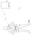
- FIG. 1is a schematic illustration of an example of portions of an implantable system 100 and portions of an environment in which it is used.
- FIG. 2is a schematic/block diagram illustrating one example of portions of a telemetry power management system for an implantable medical device.
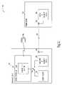
- FIG. 3Ais a schematic/block diagram illustrating one example of portions of a telemetry power management system controlling power-on by using a telemetry activation signal detector including a low power radio receiver.
- FIG. 3Bis a schematic illustrating one example of the low power radio receiver.
- FIG. 4is a flow chart illustrating one example of a method corresponding to the example of FIG. 3A .
- FIG. 5is a schematic/block diagram illustrating one example of portions of a telemetry power management system controlling power-on by detecting a physical activity.
- FIG. 6is a flow chart illustrating one example of a method corresponding to the example of FIG. 5 .
- FIG. 7is a schematic illustration of one example of portions of a telemetry power management system controlling power-on by activating inductive telemetry.
- FIG. 8is a schematic/block diagram illustrating one example of portions of a telemetry power management system corresponding to the example of FIG. 7 .
- FIG. 9is a flow chart illustrating one example of a method corresponding to the example of FIG. 8 .
- FIG. 10is a schematic illustration of one example of portions of a telemetry power management system controlling power-on by creating a magnetic field near the implantable medical device.
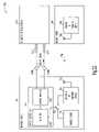
- FIG. 11is a schematic/block diagram illustrating one example of portions of a telemetry power management system corresponding to the example of FIG. 10 .
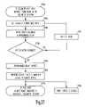
- FIG. 12is a flow chart illustrating one example of a method corresponding to the example of FIG. 11 .
- FIG. 13is a schematic illustration of one example of portions of a telemetry power management system controlling power-on by introducing a signal through an electrocardiograph (ECG) system.
- ECGelectrocardiograph
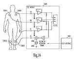
- FIG. 14is a circuit diagram illustrating one example of portions of the telemetry power management system of FIG. 13 .
- FIG. 15is a schematic illustration of another example of portions of a telemetry power management system controlling power-on by introducing a signal through an electrocardiograph (ECG) system.
- ECGelectrocardiograph
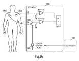
- FIG. 16is a circuit diagram illustrating one example of portions of the telemetry power management system of FIG. 15 .
- FIG. 17is a schematic/block diagram illustrating one example of portions of a telemetry power management system corresponding to the examples of FIGS. 14 and 16 .
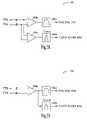
- FIG. 18is a schematic/block diagram illustrating one example of portions of a sensing amplifier.
- FIG. 19is a schematic/block diagram illustrating another example of portions of a sensing amplifier.
- FIG. 20is a flow chart illustrating one example of a method corresponding to the example of FIG. 17 .
- FIG. 21is a schematic illustration of one example of portions of a telemetry power management system controlling power-on by using an external telemetry activation device.
- FIG. 22is a schematic/block diagram illustrating one example of portions of telemetry power management system corresponding to the example of FIGS. 21 .
- FIG. 23is a flow chart illustrating one example of a method corresponding to the example of FIG. 22 .
- FIG. 24is a schematic/block diagram illustrating one example of portions of a telemetry power management system controlling power-off by sending a command via RF telemetry.
- FIG. 25is a flow chart illustrating one example of a method corresponding to the example of FIG. 24 .
- FIG. 26is a schematic/block diagram illustrating one example of portions of a telemetry power management system controlling power-off by using a timer.
- FIG. 27is a flow chart illustrating one example of a method corresponding to the example of FIG. 26 .
- FIG. 28is a flow chart illustrating one example of a method corresponding to one example of a telemetry power management system controlling power-off by using an inductive telemetry.
- This documentdiscusses, among other things, power management of telemetry circuit in an implantable medical device.
- the present methods and apparatuseswill be described in applications involving implantable cardiac rhythm management systems such as pacemakers, CRT devices, cardioverter/defibrillators, and pacer/defibrillators.
- implantable cardiac rhythm management systemssuch as pacemakers, CRT devices, cardioverter/defibrillators, and pacer/defibrillators.
- the present methods and apparatusesmay be employed in other types of implantable medical devices, including, but not being limited to, neurological stimulators, neuromuscular stimulators, drug delivery systems, and various types of physiological signal monitoring devices.
- FIG. 1is a schematic illustration of an example of portions of a medical system 100 and portions of an environment in which it is used.
- system 100is a cardiac rhythm management system including, among other things, an implanted device 110 and a remote external device 140 .
- Implanted device 110is implanted within a patient's body 101 and coupled to the patient's heart 102 by a lead system 105 .
- Examples of implanted device 110include pacemakers, CRT devices, cardioverter/defibrillators, and pacer/defibrillators.
- Remote external device 140provides a user interface for system 100 . The user interface allows a physician or other caregiver to interact with implanted device 110 through a wireless telemetry link.
- FIG. 1is a schematic illustration of an example of portions of a medical system 100 and portions of an environment in which it is used.
- system 100is a cardiac rhythm management system including, among other things, an implanted device 110 and a remote external device 140 .
- Implanted device 110is
- the wireless telemetry linkis a radio-frequency (RF) telemetry link 150 supported by RF transceivers residing in implanted device 110 and external device 140 .
- RF telemetry link 150provides for bi-directional data communication between implanted device 110 and remote device 140 .
- RF telemetry link 150provides for data transmission from implanted device 110 to remote device 140 . This may include, for example, transmitting real-time physiological data acquired by implanted device 110 , extracting physiological data acquired by and stored in implanted device 110 , extracting therapy history data stored in implanted device 110 , and extracting data indicating an operational status of implanted device 110 (e.g., battery status and lead impedance).
- RF telemetry link 150transmits data from remote device 140 to implanted device 110 . This may include, for example, programming implanted device 110 to acquire physiological data, programming implanted device 110 to perform at least one self-diagnostic test (such as for a device operational status), and programming implanted device 110 to deliver at least one therapy.
- RF telemetry link 150is a far-field telemetry link.
- a communication range of RF telemetry link 150(a distance over which data is capable of being wirelessly communicated) is at least six feet but can be as long as allowed by the particular communication technology.
- RF telemetry link 150frees the patient from any physical restraints caused by the wand and the cable.
- the power consumed by implanted device 110 to support a far-field RF telemetrycan be as high as ten thousand times that of inductive telemetry.
- the present inventorshave recognized the need for power management to reduce the energy drawn from implanted device 110 to support the RF telemetry link 150 .
- FIG. 2is a schematic/block diagram illustrating one example of portions of a telemetry power management system for implantable medical device.
- implantable medical system 100includes implanted device 110 , external remote device 140 , and RF telemetry link 150 .
- Remote device 140includes a remote RF telemetry circuit 242 and a remote antenna 243 .
- Implanted device 110includes an energy source 211 , an implanted RF telemetry circuit 212 , an implanted antenna 213 , and a switch controller 214 .
- RF telemetry circuits 212 and 242through antenna 213 and 243 , respectively, communicate using RF telemetry link 150 .
- a power switch 215when closed, connects implanted RF telemetry circuit 212 to energy source 211 to draw energy therefrom.
- RF telemetry circuit 212In many applications of system 100 , data is being transmitted for a small fraction of the time when implanted device 110 is in use. Therefore, RF telemetry circuit 212 only needs to be powered during a data transmission (and for a short preceding power-up period).
- an output of switch controller 214drives power switch 215 .
- Switch controller 214closes power switch 215 when implantable RF telemetry circuit 212 is powered to support the data transmission over RF telemetry link 150 and opens power switch 215 shortly after the data transmission is completed.
- This documentpresents several specific illustrative examples of controlling the power-on and power-off status of RF telemetry circuit 212 , such as by closing and opening power switch 215 , respectively. The examples can be combined in any way.
- power switchrefers generally to any power connection module, not limited to an on/off switch, that, in one example controls an activation (or power-on) and deactivation (or power-off) of the RF telemetry.
- the RF telemetry circuitis powered on, or activated, when it enters an energization state that enables it to perform its intended telemetry function.
- the RF telemetry circuitis powered off, or deactivated, when it enters another energization state that maintains the circuit off or in a “sleep” or “barely awake” mode to conserve energy.
- the power switchconnects/disconnects power from the energy source to one or more portions of the RF telemetry circuit.
- power switch 215connects/disconnects power from energy source 211 to portions of RF telemetry circuit 212 . After the telemetry session is terminated, power switch 215 disconnects power from the portions of RF telemetry circuit 212 but maintains power connection to other portions of RF telemetry circuit 212 , such that RF telemetry circuit 212 may be activated quickly when a new telemetry session is initiated.
- FIG. 3Ais a schematic/block diagram illustrating one example of portions of a telemetry power management system controlling power-on of at least a portion of the telemetry.
- power switch 215is closed to connect power from energy source 211 to implanted RF telemetry circuit 212 when implanted device 110 receives an radio signal.
- Remote device 140includes a telemetry activation signal generator 346 coupled to remote antenna 243 .
- Switch controller 214includes a telemetry activation signal detector 316 coupled to implanted antenna 213 .
- Telemetry activation signal detector 316includes a low power radio receiver 317 . Low power radio receiver 317 is always awake to respond to telemetry activation signals.
- a telemetry activation signalis generated by telemetry activation signal generator 346 and emitted through remote antenna 243 .
- telemetry activation signal detector 316closes power switch 215 to operate implanted RF telemetry circuit 212 .
- the telemetry activation signalis a radio signal having an amplitude and frequency in compliance with applicable government regulations.
- the telemetry activation signalis a high-power RF burst signal.
- FIG. 3Bis a schematic illustrating one example of low power radio receiver 317 .
- Low power radio receiverincludes a tank circuit 318 , a diode 319 , a low-pass filter 320 , and a low-power comparator 321 .
- Tank circuitcoupled to antenna 213 to receive a signal including the telemetry activation signal, includes an inductor and a capacitor to form a high-Q resonant circuit that obtains a gain passively.
- Diode 319is a non-linear element for rectifying the received signal.
- Low pass filter 320includes a resistor and a capacitor to detect an envelope of the rectified signal.
- Low power comparatorgenerates an output indicating a detection of the telemetry activation signal when at least a portion of the envelope exceed a predetermined detection threshold.
- low power radio receiveroperates with a supply current of approximately 100 nA-500 nA.
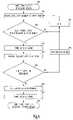
- FIG. 4is a flow chart illustrating one example of a method corresponding to the example of FIG. 3A .
- an RF telemetry sessionis initiated at remote device 140 .
- the RF telemetry sessionis initiated by a physician or other caregiver.
- the RF telemetry sessionis initiated automatically by remote device 140 , e.g., occasionally or periodically.
- the RF telemetry sessionis initiated for a regular check-up of a status of the device and conditions of the patient in whom the device is implanted.
- the RF telemetry sessionis initiated in response to a phone from a person, such as a caregiver or the patient, regarding a condition of the patient that needs immediate attention.
- remote device 140sends out a telemetry activation signal.
- the telemetry activation signalis a radio signal having an amplitude and frequency in compliance with applicable government regulations.
- the telemetry activation signalis an RF burst.
- the RF bursthas a duration of up to five milliseconds and an amplitude sufficient to be received by implanted RF telemetry circuit 212 up to a predetermined distance from remote device 140 .
- the RF burst received at implanted RF telemetry circuit 212has an amplitude of at least 1 mV.
- the RF burst amplitude usedis determined based on an environmental noise and a signal-to-noise ratio that ensures reliable detection by diode detector 317 .
- remote devicesends a digital key that follows the telemetry activation signal.
- the digital keyis a coded signal identifying a particular implantable device 110 . If the telemetry activation signal is received by at least one implanted device 110 within the predetermined distance from remote device 140 , power switch 215 in that particular implanted device 110 is closed at 430 for connecting RF telemetry circuit 212 and energy source 211 of that implanted device 110 .
- telemetry deviceis activated to perform RF telemetry functions.
- the particular implanted device 110receives the digital key matching its identification code, it sends a responsive signal to remote device 140 .
- implanted device 110is prevented from sending out any signal after an end of the RF telemetry session until a matched digital key is received at the beginning of a new RF telemetry session.
- the reception of this responsive signal by remote device 140indicates that RF telemetry has been successfully established, i.e., RF telemetry link 150 is ready for bidirectional data transmission.
- the identification codefails to match the identification of the particular implanted device 110 , its power switch 215 is opened at 455 , and remote device 140 repeats the process at 410 after a predetermined delay 415 .
- RF telemetryAfter the RF telemetry is established at 450 , data is transmitted from remote device 140 to implanted device 110 and/or from implanted device 110 to remote device 140 at 460 .
- the RF telemetryenters an idle state following an end of the RF telemetry session, when RF telemetry circuit 212 is powered but no data is being transmitted between implanted device 110 and remote device 140 .
- power switch 215is opened at 470 to disconnect power to at least a portion of RF telemetry circuit 212 . Examples of methods and apparatus controlling the opening of power switch 215 are described later in this document.
- remote device 140indicates whether the telemetry session was successful, such as by logging or displaying a message.
- FIG. 5is a schematic/block diagram illustrating another example of portions of a telemetry power management system controlling power-on of at least a portion of the telemetry.
- power switch 215is closed to connect power from energy source 211 to RF telemetry circuit 212 when a patient activity (e.g., a body motion) of a predetermined magnitude, duration, and/or pattern is detected.
- switch controller 214includes accelerometer 520 and a sensor signal processing circuit 521 . Accelerometer 520 senses acceleration of implanted device 110 , resulted from body motion of the patient.
- sensor processing circuit 521includes an amplifier and a filter to condition the activity signal sensed by accelerometer 520 and a comparator to compare the conditioned acceleration signal to a predetermined acceleration threshold. If the conditioned acceleration signal exceeds the predetermined acceleration threshold, sensor processing circuit 521 outputs a signal to close power switch 215 .
- sensor processing circuit 521further includes a pattern recognition module to detect a predetermined pattern of acceleration.
- One example of such pattern of accelerationincludes three momentary acceleration impulses that are about one second apart from each other and all exceed the predetermined acceleration threshold.
- FIG. 6is a flow chart illustrating one example of a method corresponding to the example of FIG. 5 .
- a physical movement of the patient in whom implanted device 110 is implantedinitiates an RF telemetry session.
- the patientinitiates an RF telemetry session to inform or alert a physician or caregiver of his recent or present condition.
- the patienttaps on his/her skin over implanted device 110 .
- the movement resulted from the tappingis sensed by accelerometer 520 . If the tapping results in an acceleration that exceeds a predetermined threshold acceleration level at 620 , sensor processing circuit 521 outputs a signal that closes power switch 215 at 625 .
- the tappingdoes not initiate an RF telemetry session.
- the tapping activityin addition to requiring that acceleration exceeds a predetermined threshold acceleration level, the tapping activity must also exhibit a predetermined pattern, and sensor processing circuit 521 outputs a signal to close power switch 215 at 625 .
- One suitable predetermined pattern of movementresults from tapping on the skin over the device three times in approximately one-second intervals.
- RF telemetry circuit 212is activated and ready for bi-directional communication with remote device 140 via RF telemetry link 150 . In one example, RF telemetry circuit 212 sends out a signal to remote device 140 to establish RF telemetry.
- remote device 140If the signal is received by remote device 140 , and remote device 140 is available for communication, remote device 140 sends a response signal back to implanted device 110 , and the RF telemetry is established at 640 . If the RF telemetry cannot be established, because, for example, there is no available remote device 140 within the RF telemetry range, implanted RF telemetry circuit 212 will repeat 630 after a predetermined delay 645 .
- delay 645is a programmable constant. A suitable range of this constant is 0.5 to 2 seconds.
- delay 645is a function of the number of unsuccessful attempts to establish the RF telemetry. This function represents a particular sequence of successive attempts to establish the RF telemetry.
- remote device 140occasionally or periodically sends a signal including a digital key identifying a particular implantable device 110 .
- RF telemetry circuit 212sends out a signal to remote device 140 to establish RF telemetry at 640 .
- implantable device 110is prevented from starting RF telemetry communications without an authorization from remote device 140 .
- implant device 110need not make repeated attempts to establish RF telemetry, thereby saving energy.
- remote device 140indicates whether the telemetry session was successful, such as by logging or displaying a message.
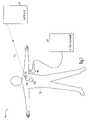
- FIG. 7is a schematic illustration of another example of portions of a telemetry power management system controlling power-on of at least a portion of the telemetry.
- system 100includes an additional remote device, such as an external programmer 745 .
- External programmer 745 and implanted device 110include respective circuits providing an inductive telemetry link 755 .
- Inductive telemetry link 755uses mutual inductance between two closely placed coils, one at implanted device 110 and the other carried by a wand 746 .
- Wand 746is coupled to the external programmer 745 via a cable.
- external programmer 745sends implanted device 110 a synchronization signal to establish inductive telemetry link 755 .
- the establishment of inductive telemetry link 755initiates the process of establishing the RF telemetry session. This process includes that the implanted device 110 powers up its RF telemetry circuit and sends a signal to remote device 140 .
- the RF telemetryis established when implanted device 110 receives a response signal from remote device 140 .
- remote device 140 and programmer 745are physically integrated into one single device.
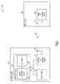
- FIG. 8is a schematic/block diagram illustrating one example of portions of a telemetry power management system corresponding to the example of FIG. 7 .
- system 100includes implanted device 110 , remote device 140 , and external programmer 745 .
- remote device 140 and programmer 745are physically integrated into one single device.
- Implanted device 110communicates with remote device 140 via RF telemetry link 150 , or with external programmer 745 via inductive telemetry link 755 .
- External programmer 745includes an external inductive telemetry circuit 847 .
- Switch controller 214 in implanted device 110includes an implantable inductive telemetry circuit 828 including an output that controls power switch 215 .
- Inductive telemetry link 755uses mutual inductance between coil 829 and another coil in wand 746 .
- the coil in wand 746is electrically connected to external inductive telemetry circuit 847 .
- Switch 215is closed to connect power from energy source 211 to RF telemetry circuit 212 after implanted inductive telemetry circuit 828 becomes active, i.e., after inductive telemetry link 755 is ready for bidirectional data communication.
- the inductive telemetryneed not remain active after the RF telemetry is established.
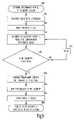
- FIG. 9is a flow chart illustrating one example of a method corresponding to the example of FIG. 8 .
- a physician or other caregiverinitiates an RF telemetry session by placing or waving wand 746 near implanted device 110 .
- the RF telemetry sessionis initiated for evaluating a patient's condition, and RF telemetry provides patient mobility after wand 746 is removed.
- the RF telemetry sessionis initiated just before implanted device 110 is implanted in a patient. The RF telemetry avoids bringing wand 746 into the sterile field of the operation.
- inductive telemetry link 755is established.
- External programmer 745indicates whether inductive telemetry link 755 was successfully established. If establishment of inductive telemetry link 755 was unsuccessful, the physician or other caregiver adjusts the position of wand 746 until such success is obtained. In one example, external programmer 745 sends a synchronization signal to implanted device 110 . Upon receiving the synchronization signal, implanted inductive telemetry circuit 828 sends a return signal back to external programmer 745 , and inductive link 755 is established at 910 when external inductive telemetry circuit 847 receives the return signal. At 920 , power switch 215 is closed to connect power from energy source 211 to implanted RF telemetry circuit 212 .
- RF telemetry circuit 212is activated and ready for bi-directional communication with remote device 140 via RF telemetry link 150 .
- implanted RF telemetry circuit 212sends a signal to remote device 140 . If the signal is received by remote device 140 , and remote device 140 is not busy with ongoing telemetry with other implantable device(s), remote device 140 sends a responsive signal back to implanted device 110 , and the RF telemetry is established at 940 . If the RF telemetry cannot be established at 940 , because, for example, there is no available remote device 140 within the RF telemetry range, RF telemetry circuit 212 will repeat 930 after a delay 945 .
- delay 945is a programmed constant. In another example, delay 945 is a function of the number of unsuccessful attempts to establish the RF telemetry. This function represents a particular sequence of successive attempts to establish the RF telemetry.
- remote device 140periodically sends a signal including a digital key identifying a particular implantable device 110 . Only upon receiving this signal, RF telemetry circuit 212 sends out a signal to remote device 140 to establish RF telemetry at 940 .
- external programmer 745indicates whether RF telemetry link 150 has been established. In one example, the physician or caregiver may then remove wand 746 from near implanted device 110 at 950 , leaving the patient free of cable attachment.
- the physician or caregivermust remove wand 746 from near implanted device 110 at 950 before the RF telemetry can be established because the inductive telemetry is given priority over the RF telemetry.
- datais transmitted from remote device 140 to implanted device 110 and/or from implanted device 110 to remote device 140 .
- power switch 215is opened at 970 to disconnect power from energy source 211 to at least a portion of RF telemetry circuit 212 . Examples of methods and apparatuses controlling the opening of power switch 215 are described later in this document.
- remote device 140indicates whether the telemetry session was successful, such as by logging or displaying a message.
- FIG. 10is a schematic illustration of another example of portions of a telemetry power management system controlling power-on of at least a portion of the telemetry.
- system 100includes a magnetic field provider 1048 .
- the RF telemetry sessionis initiated when implanted device 110 detects a magnet field.
- magnetic field provider 1048includes a permanent magnet.
- magnetic field provider 1048includes a hand-held, battery-powered magnetic field provider, such as a wireless, battery operated inductive wand.
- magnetic field provider 1048is an external programmer including an inductive telemetry circuit or other circuit or other device generating a magnetic field.
- FIG. 11is a schematic/block diagram illustrating one example of portions of a telemetry power management system corresponding to the example of FIG. 10 .
- system 100includes implanted device 110 , remote device 140 , and magnetic field provider 1048 .
- Switch controller 214 in implanted device 110includes a reed switch or other magnetic field detector 1130 that controls power switch 215 .
- Power switch 215is closed to connect power from energy source 211 to RF telemetry circuit 212 when a magnetic field is detected by magnetic field detector 1130 exceeds a threshold.
- FIG. 12is a flow chart illustrating one example of a method corresponding to the example of FIG. 11 .
- a physician or other caregiverinitiates an RF telemetry session by momentarily waving magnetic field provider 1048 near implanted device 110 .
- the RF telemetry sessionallows evaluation of a patient's condition while providing patient mobility.
- the magnetic field from magnetic field provider 1048is detected by magnetic field detector 1130 when the field strength exceeds a threshold level.
- power switch 215is closed to connect power from energy source 211 to implanted RF telemetry circuit 212 .
- RF telemetry circuit 212is activated and ready for bi-directional communication with remote device 140 via RF telemetry link 150 .
- implanted RF telemetry circuit 212sends a signal to remote device 140 . If the signal is received by remote device 140 , and remote device 140 is not busy communicating with other implantable device(s), remote device 140 sends a responsive signal back to implanted device 110 , establishing RF telemetry at 1240 . If the RF telemetry cannot be established at 1240 , because, for example, there is no available remote device 140 within the RF telemetry range, RF telemetry circuit 212 will repeat 1230 after a delay 1245 . In one example, delay 1245 is a programmed constant.
- delay 1245is a function of the number of unsuccessful attempts to establish the RF telemetry. This function represents a particular sequence of successive attempts to establish the RF telemetry.
- remote device 140periodically sends a signal including a digital key identifying a particular implantable device 110 . Only upon receiving this signal, RF telemetry circuit 212 sends out a signal to remote device 140 to establish RF telemetry at 1240 .
- datais transmitted from remote device 140 to implanted device 110 and/or from implanted device 110 to remote device 140 .
- power switch 215is opened at 1260 to disconnect power from energy source 211 to at least a portion of RF telemetry circuit 212 . Examples of methods and apparatus controlling the opening of power switch 215 are described later in this document.
- remote device 140indicates whether the telemetry session was successful, such as by logging or displaying a message.
- FIG. 13is a schematic illustration of another example of portions of a telemetry power management system controlling power-on of at least a portion of the telemetry by using an electrocardiograph (ECG) monitoring or recording system.
- remote device 140includes an ECG monitoring or recording module 1360 .
- ECG module 1360is used for assessing the behavior of implanted device 110 by observing the cardiac signals, such as through surface electrodes 1361 A-D attached to a patient's skin. Once electrodes 1361 A-D are electrically coupled to ECG module 1360 , a low-amplitude electrical current signal is sent to the body from remote device 140 , through two or more of electrodes 1361 .
- This current signalis sensed by implanted device 110 as a telemetry power-on signal.
- the low-amplitude electrical current signalincludes an encoded command that can be easily distinguished from noise that may be present on electrodes 1361 . Once RF telemetry link 150 has been established, electrodes 1361 need not remain attached during the subsequent telemetry session.
- FIG. 14is a circuit diagram illustrating one example of portions of the telemetry power management system of FIG. 13 .
- ECG module 1360is coupled to electrodes 1361 , including three input electrodes 1361 B-D and one right-leg negative feedback electrode 1351 A.
- Right-leg negative feedbackis a technique known in the art of ECG monitoring or recording for reducing noise pickup due to a common-mode voltage on electrodes 1361 B-D while increasing patient safety.
- ECG module 1360includes a telemetry activation signal generator 1465 and a signal summing circuit 1466 .
- a physician or other caregiverinitiates an RF telemetry session by providing an input at a user interface 1467 . This input causes signal generator 1465 to issue a telemetry activation signal.
- signal generator 1465automatically issues a telemetry activation signal upon a predetermined event. This signal is summed into the negative feedback circuit and introduced into the patient's body via electrode 1361 A.
- the telemetry activation signalhas a frequency much greater than 150 Hz. This allows the telemetry activation signal to be filtered out from the monitored ECG signal sensed by electrodes 1361 B-D.
- FIG. 15is a schematic illustration of another example of portions of a telemetry power management system controlling power-on of at least a portion of the telemetry by using an electrocardiograph (ECG) system.
- ECG module 1360is used for assessing the behavior of implanted device 110 by observing the cardiac signals through two input electrodes 1361 C-D attached to the body surface. At least a portion of the telemetry circuit in implanted device 110 is powered on in response to a telemetry activation current signal injected into the body via electrodes 1361 C-D.
- FIG. 16is a circuit diagram illustrating one example of portions of the telemetry power management system of FIG. 15 .
- ECG module 1360is configured to operate using input electrodes 1361 B-D, without right-leg negative feedback electrode 1351 A.
- One of input electrodes 1361 C and 1361 Dis used as an output for telemetry activation signal generator 1465 , such as by using a switch 1667 .
- a physician or other caregiverinitiates an RF telemetry session by providing an input to user interface 1467 . This input causes remote device 140 to inject telemetry activation signal via input electrode 1361 C.
- FIG. 17is a schematic/block diagram illustrating one example of portions of system 100 corresponding in the examples of FIGS. 14 and 16 .
- remote device 140includes ECG module 1360 , which is coupled to electrodes 1361 attached to the patient. Electrodes 1361 include four electrodes, 1361 A-D, or alternatively, two electrodes, 1361 C-D, as respectively discussed above for FIGS. 14 and 16 .
- Switch controller 214includes a sensing amplifier 1731 and detector 1732 . In one example, in addition to sensing the telemetry activation signal, sensing amplifier 1731 is also used to sense a physiological signal. Examples of the sensed physiological signal include a cardiac signal, a respiration signal, and an acceleration signal.
- sensing amplifier 1731is used to sense cardiac signals via electrodes 1733 A and 1733 B. Electrodes 1733 A-B are both electrically coupled to sensing amplifier 1731 , such as through lead wires. In one example, electrodes 1733 A-B are disposed in close proximity to each other in or about a heart chamber. This is referred to as bipolar sensing. In an alternative example, electrode 1733 A is disposed in or about a heart chamber, and electrode 1733 B is located at or near a metal housing of implanted device 110 that houses switch controller 214 , energy source 211 , and implanted RF telemetry circuit 212 . This is referred to as unipolar sensing. Sensing amplifier 1731 typically includes an amplifier and a filter.
- Detector 1732includes a comparator having one input coupled to the output of the sensing amplifier 1731 , another input representative of a predetermined comparison threshold, and an output indicating whether the signal sensed via electrodes 1733 A-B exceeds the threshold.
- the output of detector 1732is coupled to power switch 215 to close power switch 215 when the telemetry activation signal sensed through electrodes 1733 A-B exceeds the threshold. This, in turn, connects power from energy source 211 to implanted RF telemetry circuit 212 .
- detector 1732further includes a binary code detector that detects a digital key, also sensed via electrodes 1733 A-B. In one example, use of the digital key provides added noise immunity.
- the digital keyalso identifies a particular implantable device 110 with which RF telemetry link 150 is to be established.
- Power switch 215is closed when the telemetry activation signal sensed through electrodes 1733 A-B exceeds the threshold and a matching digital key is detected.
- FIG. 18is a schematic/block diagram illustrating one example of portions of sensing amplifier 1731 .
- amplifier 1834 Ais a low-frequency amplifier used to amplify the physiological signal.
- Amplifier 1834 Bis a high-frequency amplifier used to amplify the telemetry activation signal.
- a filter 1835 Aattenuates signals that are not at the physiological signal frequency. This configuration is suitable when a telemetry activation signal has a frequency that is significantly different from the physiological signal frequency, avoiding the use of a wideband amplifier that may expose implantable device 110 to a wide range of noises.
- the physiological signalis a cardiac signal
- filter 1835 Aincludes a bandpass filter having a bandwidth of 150 Hz.
- Filter 1835 Bpasses the telemetry activation signal to detector 1732 , and attenuates signals at other frequencies. This example uses a telemetry activation signal frequency that is different, and therefore distinguishable, from that of the cardiac or other physiological signal.
- FIG. 19is a schematic/block diagram illustrating another example of portions of sensing amplifier 173 1 .
- sensing amplifier 1731includes a shared amplifier 1834 A and two filters 1835 A-B, both coupled to the output of amplifier 1834 A.
- This configurationis alternative implementation to that of FIG. 18 , eliminating components, however, the implementation of FIG. 18 allows more design flexibility in the signal processing.
- the physiological signal sensed during particular time periods and the telemetry activation signalis sensed during other times. For example, a respiration signal is monitored by periodically sensing body impedance. A telemetry activation signal is injected into the body when the body impedance is not being sensed.
- FIG. 20is a flow chart illustrating one example of a method corresponding to the example of FIG. 17 .
- a physician or other caregiverinitiates an RF telemetry session by providing input at a user interface.
- a telemetry activation signalis introduced into a patient's body through ECG electrodes 1361 .
- the telemetry activation signalis a short-duration electrical current signal flowing into the body when a switch in remote device 140 is momentarily closed.
- the telemetry activation signalincludes a digital key identifying a particular implantable device 110 with which RF telemetry link 150 is to be established.
- the RF telemetry sessionis initiated for an evaluation of a patient's conditions.
- the telemetry activation signalis detected by implanted device 110 .
- power switch 215is closed to connect power from energy source 211 to implanted RF telemetry circuit 212 .
- RF telemetry circuit 212is activated and ready for bi-directional communication with remote device 140 via RF telemetry link 150 .
- implanted RF telemetry circuit 212sends a signal to remote device 140 . If the signal is received by remote device 140 , and remote device 140 is not busy communicating with other implantable device(s), remote device 140 sends a responsive signal back to implanted device 110 , and the RF telemetry is established.
- delay 2045is a programmed constant.
- delay 2045is a function of the number of failed attempts to establish the RF telemetry. This function represents a particular sequence of successive attempts to establish the RF telemetry.
- remote device 140periodically sends a signal including a digital key identifying a particular implantable device 110 . Only upon receiving this signal, RF telemetry circuit 212 sends out a signal to remote device 140 to establish RF telemetry at 2040 . At 2050 , remote device 140 indicates that RF telemetry link 150 has been established.
- the physician or caregivermay remove ECG electrodes 1361 so that the patient's mobility is no longer limited by their connecting cable.
- datais transmitted from remote device 140 to implanted device 110 and/or from implanted device 110 to remote device 140 .
- power switch 215is opened at 2070 . This disconnects power from energy source 211 to at least a portion of RF telemetry circuit 212 . Examples of methods and apparatus controlling the opening of power switch 215 are described later in this document.
- remote device 140indicates whether the telemetry session was successful, such as by logging or displaying a message.
- FIG. 21is a schematic illustration of another example of portions of a telemetry power management system controlling power-on of at least a portion of the telemetry by using an external telemetry activation device.
- system 100includes a telemetry activation device 2170 that introduces a telemetry activation signal into a patient's body to be received by implanted device 110 for activating telemetry.
- the telemetry activation signalincludes an encoded command that is distinguishable from noise that may be present on electrodes 2171 .
- device 2170is dedicated to telemetry activation.
- device 2170is a monitoring device, or a therapy device, or any medical device or non-medical device incorporating a telemetry activation system.
- device 2170includes a user input and/or output interface such as to accept commands and display telemetry activity or other status information regarding implanted device 110 .
- Telemetry activation device 2170includes a pair of conductive structures 2171 for contact with the patient. A small electrical current flows into the patient's body when the patient contacts both conductive structures.
- the conductive structuresinclude a pair of conductive joysticks. The patient holds one joystick in each hand to initiate an RF telemetry session for data transmission between implanted device 110 and remote device 140 .
- conductive structure 2171includes two conductive patches incorporated onto a bar, a handle, or any portion of the housing of telemetry activation device 2170 .
- the patientinitiates telemetry sessions periodically to transfer acquired physiological data and/or therapy history to a physician or other caregiver.
- the patientinitiates a telemetry session when attention of the physician or other caregiver is needed.
- FIG. 22is a schematic/block diagram illustrating one example of portions of telemetry power management system corresponding to the example of FIG. 21 .
- system 100includes a telemetry activation device 2170 having conductive structures 2171 .
- Switch controller 214includes sensing amplifier 1731 and detector 1732 .
- sensing amplifier 1731is also used to sense a physiological signal via electrodes 1733 A-B that are electrically coupled to sensing amplifier 1731 .
- the sensed physiological signalis a cardiac signal.
- Electrodes 1733 A-Bare configured for either bipolar sensing or unipolar sensing.
- Power switch 215is closed to connect power from energy source 211 to implanted RF telemetry circuit 212 in response to the telemetry activation signal being sensed by sensing amplifier 1731 and detected by detector 1732 .
- FIG. 23is a flow chart illustrating one example of a method corresponding to the example of FIG. 22 .
- a userinitiates an RF telemetry session as scheduled or needed.
- the useris a patient.
- the useris a physician or other caregiver who is supervising or examining the patient.
- the userselects an operation.
- the usermay elect to transfer data from implanted device 110 to remote device 140 immediately or after a delay. If the user elects to transfer data after a delay, then at 2315 , telemetry activation device 2170 prompts the user to enter a time for the data transfer.
- telemetry activation device 2170prompts the user to contact conductive structures 2171 .
- telemetry activation device 2170prompts the user to grab the conductive joysticks on the device.
- power switch 215is closed to connect power from energy source 211 to implanted RF telemetry circuit 212 .
- RF telemetry circuit 212is activated and ready for bi-directional communication with remote device 140 via RF telemetry link 150 .
- implanted RF telemetry circuit 212sends a signal to remote device 140 .
- remote device 140If the signal is received by remote device 140 , and remote device 140 is available to communicate with an implantable device, remote device 140 sends a responsive signal back to implanted device 110 , and the RF telemetry is established at 2350 . If the RF telemetry cannot be established at 2350 , because of excessive environmental noise or other reasons, RF telemetry circuit 212 will repeat 2340 after a delay 2355 .
- delay 2355is a programmed constant.
- delay 2355is a function of the number of failed attempts to establish the RF telemetry. This function represents a particular sequence of successive attempts to establish the RF telemetry.
- remote device 140periodically sends a signal including a digital key identifying a particular implantable device 110 .
- RF telemetry circuit 212Only upon receiving this signal, RF telemetry circuit 212 sends out a signal to remote device 140 to establish RF telemetry at 2350 .
- remote device 140indicates whether RF telemetry link 150 has been established. If so, the user may then remove hands from conductive structures 1371 .
- datais transmitted from remote device 140 to implanted device 110 and/or from implanted device 110 to remote device 140 . After data communication is complete, the RF telemetry enters an idle state. Power switch 215 is then opened at 2380 to disconnect power from energy source 211 to at least a portion of PF telemetry circuit 212 . Examples of methods and apparatuses controlling the opening of power switch 215 are described later in this document.
- remote device 140indicates whether the telemetry session was successful, such as by logging or displaying a message.
- FIG. 24is a schematic/block diagram illustrating one example of portions of a telemetry power management system controlling power-off of at least a portion of the telemetry.
- a telemetry power-off signalis sent to implanted device 110 via RF telemetry link 150 .
- the telemetry power-off signalis an encoded command, such as a unique digital code.
- switch controller 214includes a power-off signal detector 2480 coupled to antenna 213 . Upon detection of the power-off signal, detector 2480 opens power switch 215 to disconnect the power to at least a portion of implanted RF telemetry circuit 212 from energy source 211 . In a further example, detector 2480 opens power switch 215 upon detection of the power-off signal and determination that RF telemetry has entered an idle state.
- FIG. 25is a flow chart illustrating one example of a method corresponding to the example of FIG. 24 .
- remote device 140sends a power-off signal to implanted device 110 to terminate a previously-established RF telemetry session.
- a physician or other caregiverprovides a user input at a user-interface that triggers the power-off signal.
- remote device 140sends the power-off signal automatically when it determines that an RF telemetry session should end. For example, remote device 140 determines that an RF telemetry session should end when no data is transmitted via RF telemetry link 150 for a predetermined duration, such as ten minutes.
- implanted device 110receives the telemetry power-off signal.
- power-off signal detector 2480determines whether the RF telemetry is in an idle state, in which no data is being transferred between implanted device 110 and remote device 140 . In one example, if data is being transferred, or is about to be transferred, power-off signal detector 2480 repeats a step 2530 of determining whether the RF telemetry is in an idle state after a predetermined delay 2532 . At 2540 , after the RF telemetry is determined to be in an idle state, implanted device 110 sends a termination signal to remote device 140 to inform remote device 140 of the completion of the RF telemetry session.
- power switch 215is opened to disconnect the power to at least a portion of implanted RF telemetry circuit 212 from energy source 211 .
- remote device 140Upon receiving the termination signal from implanted device 110 , remote device 140 indicates a successful completion of the RF telemetry session at 2560 , such as by logging or displaying a message.
- FIG. 26is a schematic/block diagram illustrating another example of portions of a telemetry power management system controlling power-off of at least a portion of the telemetry.
- switch controller 214includes a timer 2682 coupled to implantable RF telemetry circuit 212 .
- Timer 2682starts timing an interval when the RF telemetry enters an idle state. If data transmission via the RF telemetry resumes during the predetermined delay, timer 2682 is reset and does not restart until the RF telemetry enters another idle state. If the delay expires during the idle state, timer 2682 opens power switch 215 to disconnect the power to at least a portion of implanted RF telemetry circuit 212 from energy source 211 .
- FIG. 27is a flow chart illustrating one example of a method corresponding to the example of FIG. 26 .
- an idle state of the RF telemetryterminates RF telemetry session at 2700 .
- timer 2682is then started at 2720 to measure a time spent in the idle state. If data transmission via RF telemetry link 150 resumes at 2730 , before the time value exceeds a predetermined delay, timer 2682 is reset (re-zeroed) and is to be restarted upon reentering the idle state.
- implanted device 110then sends a termination signal to remote device 140 to inform remote device 140 of the completion of the RF telemetry session.
- power switch 215is opened to disconnect the power to at least a portion of implanted RF telemetry circuit 212 from energy source 211 .
- remote device 140indicates a successful completion of the RF telemetry session, such as by logging or displaying a message.
- a physician or other caregiveruses the inductive telemetry link 755 of FIGS. 7 or 8 , to end the RF telemetry session. This allows immediate shutoff of RF telemetry link 150 regardless of whether the RF telemetry is in the idle state.
- An encoded RF telemetry power-off signalis sent from external programmer 745 to implanted device 110 through inductive telemetry link 755 .
- implanted inductive telemetry circuitopens power switch 215 to disconnect the power to at least a portion of implanted RF telemetry circuit 212 from energy source 211 .
- FIG. 28is a flow chart illustrating one example of a method corresponding to this example.
- a physician or other caregiverprovides input to a user interface that causes external programmer 745 to terminate a previously-established RF telemetry session.
- the physician or other caregiverwants to terminate RF telemetry because a check-up, diagnosis, or treatment session has been completed, and the RF telemetry is no longer needed.
- physician or other caregiverwant to establish RF telemetry with a different implanted device.
- external programmer 745Upon receiving the RF telemetry termination command, external programmer 745 sends the encoded RF telemetry power-off signal to implanted device 110 at 2810 .
- implanted device 110receives the RF telemetry power-off signal.
- implanted device 110sends a responsive termination signal to remote device 140 to inform remote device 140 and external programmer 745 of the completion of the RF telemetry session.
- power switch 215is opened to disconnect the power to at least a portion of implanted RF telemetry circuit 212 from energy source 211 .
- external programmer 745indicates termination of the RF telemetry session.
- remote device 140indicates the termination RF telemetry session, such as by logging or displaying a message.
- Power-on by RF burst signalallows an RF telemetry session to be initiated at remote device 140 .
- Thisallows a physician or other caregiver to provide care to a patient from a remote location.
- An examination of the patientmay be performed with or without the patient's knowledge.
- the patient's routine check-upis performed through the RF telemetry and telephone, so that the patient saves a trip to a physician's office.
- the patient who needs close monitoringis frequently checked by the physician or other caregiver through the RF telemetry, so that the patient need not be hospitalized to receive similar care.
- Implanted device 110already includes an accelerometer as an activity or metabolic need sensor employed in a therapy algorithm. The same accelerometer may be used for telemetry power management by modifying only software. Power-on of RF telemetry using inductive telemetry is convenient when implanted device 110 includes an inductive telemetry system. Having external programmer 745 available during an RF telemetry session also provides an alternative communications modality if RF telemetry is lost because of RF interference or other reasons. Power-on by magnetic field allows RF telemetry power management using a magnet or a hand-held device.
- implanted device 110already includes a function activated or suppressed by an external magnet. For example, holding a magnet near implanted device 110 may cause it to pace at a fixed pacing rate, overriding any therapy algorithm that would be otherwise effective.
- Using a magnetic field for RF telemetry power management in this examplemay be implemented by modifying only software. Power-on by introducing a signal via surface ECG electrodes is convenient when remote device 140 includes an ECG module. During a patient's follow-up visit to a physician, the physician typically attaches ECG electrodes to the patient to diagnose the patient's condition.
- telemetryis seamlessly automatically activated without requiring physician intervention.
- using RF telemetryprovides for a higher rate of data transmission as compared with inductive telemetry, reducing the duration of a telemetry session. Power-on by momentarily contacting an external device allows a patient to initiate and/or schedule an RF telemetry session and is convenient for patients who regularly use a medical device such as a monitor.
- the physician or other caregiverterminates an RF telemetry that is accidentally established with an unintended implantable device.
- An inductive telemetryis less likely to be accidentally established because it often requires the wand to be closely (within a few inches) coupled to the implantable device.
- the physician or other caregivermay terminate the RF telemetry by using the inductive telemetry, such as when one or more other power-off methods fail.
- the one or more other power-off methodsfail because of the presence of a noise, such as a cellular phone signal.
- one or more of the power-on methods and one or more of the power-off methods discussed abovemay be included in one implantable device.
- Using more than one method to connect/disconnect power from energy source 211 to implanted RF telemetry circuit 212 , or at least portions thereof,increases the reliability of initiating and terminating the RF telemetry session in a timely manner. This ensures patient safety, conserves energy, and hence increases device longevity. If one method fails, another available method may be automatically or manually applied.
- implanted device 110employs one power-on method but several power-off methods, such as all three discussed above. This decreases energy waste and patient risks by ensuring that implanted RF telemetry circuit 212 is deactivated as soon as the RF telemetry session ends.
- the implantable devicecan be any implantable medical device having an active electronic circuit.
- the implantable deviceshould, therefore, be determined with reference to the appended claims, along with the full scope of equivalents to which such claims are entitled.
- the terms “including” and “in which”are used as the plain-English equivalents of the respective terms “comprising” and “wherein.”
Landscapes
- Health & Medical Sciences (AREA)
- Engineering & Computer Science (AREA)
- Biomedical Technology (AREA)
- General Health & Medical Sciences (AREA)
- Public Health (AREA)
- Cardiology (AREA)
- Veterinary Medicine (AREA)
- Life Sciences & Earth Sciences (AREA)
- Animal Behavior & Ethology (AREA)
- Radiology & Medical Imaging (AREA)
- Nuclear Medicine, Radiotherapy & Molecular Imaging (AREA)
- General Business, Economics & Management (AREA)
- Business, Economics & Management (AREA)
- Heart & Thoracic Surgery (AREA)
- Physics & Mathematics (AREA)
- Epidemiology (AREA)
- Medical Informatics (AREA)
- Primary Health Care (AREA)
- Electromagnetism (AREA)
- Acoustics & Sound (AREA)
- Electrotherapy Devices (AREA)
Abstract
Description
This application is a division of U.S. patent application Ser. No. 10/071,255, filed on Feb. 7, 2002, now U.S. Pat. No. 6,985,773 the specification of which is incorporated herein by reference.
This application is related to, commonly assigned Von Arx et al. U.S. patent application Ser. No. 10/025,223, now U.S. Pat. No. 6,993,393, entitled “A TELEMETRY DUTY CYCLE MANAGEMENT SYSTEM FOR AN IMPLANTABLE MEDICAL DEVICE,” filed Dec. 19, 2001 and Von Arx et al. U.S. patent application Ser. No. 10/025,183, entitled “AN IMPLANTABLE MEDICAL DEVICE WITH TWO OR MORE TELEMETRY SYSTEMS,” filed Dec. 19, 2001, each of which is hereby incorporated by reference.
This document relates generally to implantable medical devices and particularly, but not by way of limitation, to such a device including power management of a telemetry system allowing communication with an external device.
Medical devices are implanted in human bodies for monitoring physiological conditions, diagnosing diseases, treating diseases, or restoring functions of organs or tissues. Examples of such implantable medical devices include cardiac rhythm management systems, neurological stimulators, neuromuscular stimulators, and drug delivery systems. Because such a device may be implanted in a patient for a long time, the size and power consumption of the device are inherently constrained. Consequently, an implantable device may depend on an external system to perform certain functions. Communication between the implantable device and the external system is referred to as telemetry. Examples of specific telemetry functions include programming the implantable device to perform certain monitoring or therapeutic tasks, extracting an operational status of the implantable device, transmitting real-time physiological data acquired by the implantable device, and extracting physiological data acquired by and stored in the implantable device.
One particular example of implantable medical devices is a cardiac rhythm management device implanted in a patient to treat irregular or other abnormal cardiac rhythms by delivering electrical pulses to the patient's heart. Such rhythms result in diminished blood circulation. Implantable cardiac rhythm management devices include, among other things, pacemakers, also referred to as pacers. Pacers are often used to treat patients with bradyarrhythmias, that is, hearts that beat too slowly or irregularly. Such pacers may coordinate atrial and ventricular contractions to improve the heart's pumping efficiency. Implantable cardiac rhythm management devices also include devices providing cardiac resynchronization therapy (CRT), such as for patients with congestive heart failure (CHF). CHF patients have deteriorated heart muscles that display less contractility and cause poorly synchronized heart contraction patterns. By pacing multiple heart chambers or multiple sites within a single heart chamber, the CRT device restores a more synchronized contraction of the weakened heart muscle, thus increasing the heart's efficiency as a pump. Implantable cardiac management devices also include defibrillators that are capable of delivering higher energy electrical stimuli to the heart. Such defibrillators may also include cardioverters, which synchronize the delivery of such stimuli to portions of sensed intrinsic heart activity signals. Defibrillators are often used to treat patients with tachyarrhythmias, that is, hearts that beat too quickly. In addition to pacers, CRT devices, and defibrillators, implantable cardiac rhythm management systems also include, among other things, pacer/defibrillators that combine the functions of pacers and defibrillators, drug delivery devices, and any other implantable systems or devices for diagnosing or treating cardiac arrhythmias.
Typically, an implantable cardiac rhythm management device communicates, via telemetry, with an external device referred to as a programmer. One type of such telemetry is based on inductive coupling between two closely-placed coils using the mutual inductance between these coils. This type of telemetry is referred to as inductive telemetry or near-field telemetry because the coils must typically be closely situated for obtaining inductively coupled communication. One example of such an inductive telemetry is discussed in Brockway et al., U.S. Pat. No. 4,562,841, entitled “PROGRAMMABLE MULTI-MODE CARDIAC PACEMAKER,” assigned to Cardiac Pacemakers, Inc., the disclosure of which is incorporated herein by reference in its entirety.
In one example, an implantable device includes a first coil and a telemetry circuit, both sealed in a metal housing (referred to as a “can”). The external programmer provides a second coil in a wand that is electrically connected to the programmer. During device implantation, a physician evaluates the patient's condition, such as by using the implanted device to acquire real-time physiological data from the patient and communicating the physiological data in real-time to the external programmer for processing and/or display. The physician may also program the implantable device, including selecting a pacing or defibrillation therapy mode, and parameters required by that mode, based on the patient's condition and needs. The data acquisition and device programming are both performed using the inductive telemetry. If the patient's condition is stable after implantation, he or she needs no attention from the physician or other caregiver until a scheduled routine follow-up. During a typical routine follow-up, the physician reviews the patient's history with the implantable device, re-evaluates the patient's condition, and re-programs the implantable device if necessary.
One problem with inductive telemetry is its requirement that the two coils are closely placed. This typically requires placing the wand on the body surface over the implantable device. Because the wand is electrically connected to the programmer using a cable, the inductive telemetry limits the patient's mobility.
To improve communication range and patient mobility, a far-field radio-frequency (RF) telemetry may be used, in which an RF transceiver in the implantable device is used to communicate with an RF transceiver in the external programmer. With a far-field RF telemetry, the patient is typically free of any body surface attachment that limits mobility. However, RF telemetry may consume several thousand times more energy than inductive telemetry.
For these and other reasons, the present inventors have recognized an unmet need for long-range telemetry at reduced energy consumption from the implantable device.
An implantable medical device includes a radio-frequency (RF) telemetry circuit that includes a power switch through which the RF telemetry circuit is connected to an energy source such as a battery. The power switch is closed to connect power from the energy source to the RF telemetry circuit when a user initiates an RF telemetry session. After the RF telemetry session is completed, the power switch is opened to shut off at least a portion of the RF telemetry circuit.
In one example, the RF telemetry circuit is powered on by sending a telemetry activation signal from the remote device to the implantable device. A physician or other caregiver operating the remote device initiates an RF telemetry session. The power switch is closed when the telemetry activation signal is detected by the implantable device.
In another example, the RF telemetry circuit is powered on by a physical movement sensed by an accelerometer and detected by the implantable device. A patient with the implantable device initiates an RF telemetry session by tapping on the skin over the implantable device. The power switch is closed when the implantable device detects an acceleration resulted from the tapping.
In another example, the RF telemetry circuit is powered on by activating an inductive telemetry circuit included in the implantable device. A physician or other caregiver operating an external programmer initiates an inductive telemetry operation in order to initiate an RF telemetry session. The power switch is closed when an inductive telemetry circuit in the implantable device is activated.
In another example, the RF telemetry circuit is powered on by a magnetic field detected by the implantable device. A physician or other caregiver waves a magnet or a hand held device generating a magnetic field to initiate an RF telemetry session. The power switch is closed when the magnetic filed exceeds a predetermined level and is detected by the implantable device.
In another example, the RF telemetry circuit is powered on by introducing a telemetry activation signal into the patient through a surface electrocardiography (ECG) recording system. A physician or other caregiver operating the remote device including an ECG module initiates an RF telemetry session. The power switch is closed when the telemetry activation signal is detected by a biopotential sensing circuit in the implantable device.
In another example, the RF telemetry circuit is powered on by introducing a telemetry activation signal into a patient through contacts between the patient and an external device adopted for telemetry activation. A patient initiates an RF telemetry session by contacting the external device. The power switch is closed when the telemetry activation signal is detected by a biopotential sensing circuit in the implantable device.
In one example, the RF telemetry circuit is shut off when a termination signal sent from the remote device through the RF telemetry is received by the implantable device. A physician or other caregiver operating the remote device may issue the termination signal. Alternatively, the termination signal may be sent when the remote device determines that the RF telemetry session is to be concluded. The power switch is opened when the implantable device receives the termination signal.
In another example, the RF telemetry circuit is shut off after a predetermined delay following an end of a data transmission session. A timer is started when the data transmission stops. The power switch is opened at the end of the predetermined delay if the data transmission has not resumed.
In another example, the RF telemetry circuit is shut off by activating an inductive telemetry circuit included in the implantable device. A physician or other caregiver operating an external programmer terminates an RF telemetry session. The power switch is closed immediately after the inductive telemetry circuit in the implantable device is activated.
Depending on a patient's needs for care and type of implantable device, one or more of the power-on methods and one or more of the power-off methods discussed in this document may be included in one implantable device. Using more than one method to connect/disconnect power from the energy source to the RF telemetry circuit increases the reliability of initiating and terminating the RF telemetry session in a timely manner to ensure patient safety and conserve energy and hence device longevity. Other aspects of the present systems, devices, and methods will become apparent upon reading the following Detailed Description and viewing the drawings that form a part thereof.
In the drawings, which are not necessarily drawn to scale, like numerals describe substantially similar components throughout the several views. Like numerals having different letter suffixes represent different instances of substantially similar components. The drawings illustrate generally, by way of example, but not by way of limitation, various embodiments discussed in the present document.
In the following detailed description, reference is made to the accompanying drawings that form a part hereof, and in which is shown, by way of illustration, specific embodiments in which the invention may be practiced. These embodiments are described in sufficient detail to enable those skilled in the art to practice the invention, and it is to be understood that the embodiments may be combined, or that other embodiments may be utilized and that structural, logical and electrical changes may be made without departing from the scope of the present invention. The following detailed description is, therefore, not to be taken in a limiting sense, and the scope of the present invention is defined by the appended claims and their equivalents.
This document discusses, among other things, power management of telemetry circuit in an implantable medical device. The present methods and apparatuses will be described in applications involving implantable cardiac rhythm management systems such as pacemakers, CRT devices, cardioverter/defibrillators, and pacer/defibrillators. However, it is understood that the present methods and apparatuses may be employed in other types of implantable medical devices, including, but not being limited to, neurological stimulators, neuromuscular stimulators, drug delivery systems, and various types of physiological signal monitoring devices.
In one example,RF telemetry link 150 provides for data transmission from implanteddevice 110 toremote device 140. This may include, for example, transmitting real-time physiological data acquired by implanteddevice 110, extracting physiological data acquired by and stored in implanteddevice 110, extracting therapy history data stored in implanteddevice 110, and extracting data indicating an operational status of implanted device110 (e.g., battery status and lead impedance). In a further example,RF telemetry link 150 transmits data fromremote device 140 to implanteddevice 110. This may include, for example, programming implanteddevice 110 to acquire physiological data, programming implanteddevice 110 to perform at least one self-diagnostic test (such as for a device operational status), and programming implanteddevice 110 to deliver at least one therapy.
In one example,RF telemetry link 150 is a far-field telemetry link. A far-field, also referred to as the Fraunhofer zone, refers to the zone in which a component of an electromagnetic field produced by the transmitting electromagnetic radiation source decays substantially proportionally to 1/r, where r is the distance between an observation point and the radiation source. Accordingly, far-field refers to the zone outside the boundary of r=λ/2π, where λ is the wavelength of the transmitted electromagnetic energy. In one example, a communication range of RF telemetry link150 (a distance over which data is capable of being wirelessly communicated) is at least six feet but can be as long as allowed by the particular communication technology. Unlike an inductive telemetry link using a wand placed near implanteddevice 110, typically attached to the patient, and electrically connected to remoteexternal device 140 with a cable, usingRF telemetry link 150 frees the patient from any physical restraints caused by the wand and the cable. On the other hand, the power consumed by implanteddevice 110 to support a far-field RF telemetry can be as high as ten thousand times that of inductive telemetry. To reduce the energy consumption of implanteddevice 110, the present inventors have recognized the need for power management to reduce the energy drawn from implanteddevice 110 to support theRF telemetry link 150.
In this document, “power switch” refers generally to any power connection module, not limited to an on/off switch, that, in one example controls an activation (or power-on) and deactivation (or power-off) of the RF telemetry. In one example, the RF telemetry circuit is powered on, or activated, when it enters an energization state that enables it to perform its intended telemetry function. In another example, the RF telemetry circuit is powered off, or deactivated, when it enters another energization state that maintains the circuit off or in a “sleep” or “barely awake” mode to conserve energy. In one example, the power switch connects/disconnects power from the energy source to one or more portions of the RF telemetry circuit.
In one example,power switch 215 connects/disconnects power fromenergy source 211 to portions ofRF telemetry circuit 212. After the telemetry session is terminated,power switch 215 disconnects power from the portions ofRF telemetry circuit 212 but maintains power connection to other portions ofRF telemetry circuit 212, such thatRF telemetry circuit 212 may be activated quickly when a new telemetry session is initiated.
Example of Power-On by Using a Low-Power Radio Receiver
Example of Power-On by Physical Motion
Example of Power-On by Activating Inductive Telemetry
Example of Power-On by Magnetic Field
Example of Power-On by Using Signal Introduced Via Surface ECG Electrodes
Example of Power-On by Momentary Contacting an External Device
Example of Power-Off by Sending Command Via RF Telemetry
Example of Power-Off by Timing
Example of Power-Off by Using Inductive Telemetry
In one example, onceRF telemetry link 150 has been established, a physician or other caregiver uses theinductive telemetry link 755 ofFIGS. 7 or8, to end the RF telemetry session. This allows immediate shutoff ofRF telemetry link 150 regardless of whether the RF telemetry is in the idle state. An encoded RF telemetry power-off signal is sent fromexternal programmer 745 to implanteddevice 110 throughinductive telemetry link 755. Upon detection of the RF telemetry power-off signal, implanted inductive telemetry circuit openspower switch 215 to disconnect the power to at least a portion of implantedRF telemetry circuit 212 fromenergy source 211.FIG. 28 is a flow chart illustrating one example of a method corresponding to this example.
In the example ofFIG. 28 , at2800, a physician or other caregiver provides input to a user interface that causesexternal programmer 745 to terminate a previously-established RF telemetry session. In one example, the physician or other caregiver wants to terminate RF telemetry because a check-up, diagnosis, or treatment session has been completed, and the RF telemetry is no longer needed. In another example, physician or other caregiver want to establish RF telemetry with a different implanted device. Upon receiving the RF telemetry termination command,external programmer 745 sends the encoded RF telemetry power-off signal to implanteddevice 110 at2810. At2820, implanteddevice 110 receives the RF telemetry power-off signal. At2830, implanteddevice 110 sends a responsive termination signal toremote device 140 to informremote device 140 andexternal programmer 745 of the completion of the RF telemetry session. At2840,power switch 215 is opened to disconnect the power to at least a portion of implantedRF telemetry circuit 212 fromenergy source 211. At2850, upon receiving the termination signal,external programmer 745 indicates termination of the RF telemetry session. At2860, if the termination signal from implanteddevice 110 is received,remote device 140 indicates the termination RF telemetry session, such as by logging or displaying a message.
Example Choice of Power On/Off Methods
Each power-on or power-off method discussed above offers advantages, which are discussed herein by way as example, and not by way of limitation. Power-on by RF burst signal allows an RF telemetry session to be initiated atremote device 140. This allows a physician or other caregiver to provide care to a patient from a remote location. An examination of the patient may be performed with or without the patient's knowledge. In one example, the patient's routine check-up is performed through the RF telemetry and telephone, so that the patient saves a trip to a physician's office. In another example, the patient who needs close monitoring is frequently checked by the physician or other caregiver through the RF telemetry, so that the patient need not be hospitalized to receive similar care. Power-on by physical activity allows an RF telemetry session to be initiated by a patient or a person with the patient. No additional external device is required. In one example, implanteddevice 110 already includes an accelerometer as an activity or metabolic need sensor employed in a therapy algorithm. The same accelerometer may be used for telemetry power management by modifying only software. Power-on of RF telemetry using inductive telemetry is convenient when implanteddevice 110 includes an inductive telemetry system. Havingexternal programmer 745 available during an RF telemetry session also provides an alternative communications modality if RF telemetry is lost because of RF interference or other reasons. Power-on by magnetic field allows RF telemetry power management using a magnet or a hand-held device. This is likely more convenient to handle thanexternal programmer 745. In one example, implanteddevice 110 already includes a function activated or suppressed by an external magnet. For example, holding a magnet near implanteddevice 110 may cause it to pace at a fixed pacing rate, overriding any therapy algorithm that would be otherwise effective. Using a magnetic field for RF telemetry power management in this example may be implemented by modifying only software. Power-on by introducing a signal via surface ECG electrodes is convenient whenremote device 140 includes an ECG module. During a patient's follow-up visit to a physician, the physician typically attaches ECG electrodes to the patient to diagnose the patient's condition. By automatically detecting when the cables from such ECG electrodes are connected to the programmer, telemetry is seamlessly automatically activated without requiring physician intervention. In another example, using RF telemetry provides for a higher rate of data transmission as compared with inductive telemetry, reducing the duration of a telemetry session. Power-on by momentarily contacting an external device allows a patient to initiate and/or schedule an RF telemetry session and is convenient for patients who regularly use a medical device such as a monitor.
Power-off by sending a command via RF telemetry deactivates implantedRF telemetry circuit 212 without wasting power by keeping the RF telemetry power on longer than necessary. However, under some circumstancesRF telemetry link 150 may be interrupted before the power-off signal is sent to implanteddevice 110. Examples of such circumstances include a strong RF noise or a patient moving beyond a range of the RF telemetry. Under such circumstances, power-off using a timer ensures that implanted RF telemetry circuit is shut off after the RF telemetry has been idle for a predetermined period of time. Power-off using inductive telemetry permits the physician or other caregiver to immediately terminate the RF telemetry at any time. In one example, the physician or other caregiver terminates an RF telemetry that is accidentally established with an unintended implantable device. An inductive telemetry is less likely to be accidentally established because it often requires the wand to be closely (within a few inches) coupled to the implantable device. In another example, the physician or other caregiver may terminate the RF telemetry by using the inductive telemetry, such as when one or more other power-off methods fail. In a further example, the one or more other power-off methods fail because of the presence of a noise, such as a cellular phone signal.
Depending on the patient's needs for care and type of implantable device, one or more of the power-on methods and one or more of the power-off methods discussed above may be included in one implantable device. Using more than one method to connect/disconnect power fromenergy source 211 to implantedRF telemetry circuit 212, or at least portions thereof, increases the reliability of initiating and terminating the RF telemetry session in a timely manner. This ensures patient safety, conserves energy, and hence increases device longevity. If one method fails, another available method may be automatically or manually applied. In one example, implanteddevice 110 employs one power-on method but several power-off methods, such as all three discussed above. This decreases energy waste and patient risks by ensuring that implantedRF telemetry circuit 212 is deactivated as soon as the RF telemetry session ends.
It is to be understood that the above description is intended to be illustrative, and not restrictive. For example, the implantable device can be any implantable medical device having an active electronic circuit. Many other embodiments will be apparent to those of skill in the art upon reviewing the above description. The scope of the invention should, therefore, be determined with reference to the appended claims, along with the full scope of equivalents to which such claims are entitled. In the appended claims, the terms “including” and “in which” are used as the plain-English equivalents of the respective terms “comprising” and “wherein.”
Claims (9)
1. A system comprising:
an implantable medical device, the implantable medical device including:
a far-field radio-frequency (RF) first telemetry circuit;
a power connection module, coupled to the first telemetry circuit, the power connection module including a first conductivity state to connect power to at least a portion of the first telemetry circuit and a second conductivity state to disconnect the power; and
a wireless signal detector including a near-field inductive second telemetry circuit coupled to the power connection module, to control the conductivity state of the power connection module according to information detected in a wireless near-field inductive signal.
2. The system ofclaim 1 , in which the second telemetry circuit includes a receiver adapted to receive the predetermined wireless signal, and in which the predetermined wireless signal includes a command for changing the conductivity state of the power connection module.
3. The system ofclaim 1 , in which the second telemetry circuit includes a receiver adapted to detect a near-field inductive signal having a predetermined frequency and to change the conductivity state of the power connection module when the near-field inductive signal is detected.
4. The system ofclaim 1 , in which the second telemetry circuit includes a receiver adapted to detect a near-field inductive telemetry communication and to change the conductivity state of the power connection module when the near-field inductive telemetry communication is detected.
5. The system ofclaim 1 , further including:
a first remote device, electromagnetically coupled to the first telemetry circuit, the first remote device including a far-field RF third telemetry circuit to provide communication with the implantable medical device for at least a six-foot range; and
a second remote device, inductively coupled to the second telemetry circuit, the second remote device including a near-field inductive fourth telemetry circuit to provide near-field communication with the implantable medical device.
6. The system ofclaim 5 , in which the first and second remote devices are physically integrated.
7. A system comprising:
an implantable medical device, the implantable medical device including:
a far-field radio-frequency (RF) first telemetry circuit;
a power connection module, coupled to the first telemetry circuit, the power connection module including a first conductivity state to connect power to at least a portion of the first telemetry circuit and a second conductivity state to disconnect the power; and
a wireless signal detector including a low power radio detector adapted to detect information included in a predetermined telemetry activation signal to determine a conductivity state of the first telemetry circuit.
8. The system ofclaim 7 , in which the predetermined telemetry activation signal includes an RF burst and a digital key adapted to identify a particular implantable medical device.
9. The system ofclaim 7 , further including a remote device including a telemetry activation signal generator configured to be electromagnetically coupled to the low power radio detector.
Priority Applications (3)
| Application Number | Priority Date | Filing Date | Title |
|---|---|---|---|
| US11/244,273US7668596B2 (en) | 2002-02-07 | 2005-10-05 | Methods and apparatuses for implantable medical device telemetry power management |
| US12/684,303US8538528B2 (en) | 2002-02-07 | 2010-01-08 | Methods and apparatuses for implantable medical device telemetry power management |
| US14/019,830US8792983B2 (en) | 2002-02-07 | 2013-09-06 | Methods and apparatuses for implantable medical device telemetry power management |
Applications Claiming Priority (2)
| Application Number | Priority Date | Filing Date | Title |
|---|---|---|---|
| US10/071,255US6985773B2 (en) | 2002-02-07 | 2002-02-07 | Methods and apparatuses for implantable medical device telemetry power management |
| US11/244,273US7668596B2 (en) | 2002-02-07 | 2005-10-05 | Methods and apparatuses for implantable medical device telemetry power management |
Related Parent Applications (1)
| Application Number | Title | Priority Date | Filing Date |
|---|---|---|---|
| US10/071,255DivisionUS6985773B2 (en) | 2002-02-07 | 2002-02-07 | Methods and apparatuses for implantable medical device telemetry power management |
Related Child Applications (1)
| Application Number | Title | Priority Date | Filing Date |
|---|---|---|---|
| US12/684,303DivisionUS8538528B2 (en) | 2002-02-07 | 2010-01-08 | Methods and apparatuses for implantable medical device telemetry power management |
Publications (2)
| Publication Number | Publication Date |
|---|---|
| US20060025834A1 US20060025834A1 (en) | 2006-02-02 |
| US7668596B2true US7668596B2 (en) | 2010-02-23 |
Family
ID=27659190
Family Applications (4)
| Application Number | Title | Priority Date | Filing Date |
|---|---|---|---|
| US10/071,255Expired - Fee RelatedUS6985773B2 (en) | 2002-02-07 | 2002-02-07 | Methods and apparatuses for implantable medical device telemetry power management |
| US11/244,273Expired - LifetimeUS7668596B2 (en) | 2002-02-07 | 2005-10-05 | Methods and apparatuses for implantable medical device telemetry power management |
| US12/684,303Expired - LifetimeUS8538528B2 (en) | 2002-02-07 | 2010-01-08 | Methods and apparatuses for implantable medical device telemetry power management |
| US14/019,830Expired - Fee RelatedUS8792983B2 (en) | 2002-02-07 | 2013-09-06 | Methods and apparatuses for implantable medical device telemetry power management |
Family Applications Before (1)
| Application Number | Title | Priority Date | Filing Date |
|---|---|---|---|
| US10/071,255Expired - Fee RelatedUS6985773B2 (en) | 2002-02-07 | 2002-02-07 | Methods and apparatuses for implantable medical device telemetry power management |
Family Applications After (2)
| Application Number | Title | Priority Date | Filing Date |
|---|---|---|---|
| US12/684,303Expired - LifetimeUS8538528B2 (en) | 2002-02-07 | 2010-01-08 | Methods and apparatuses for implantable medical device telemetry power management |
| US14/019,830Expired - Fee RelatedUS8792983B2 (en) | 2002-02-07 | 2013-09-06 | Methods and apparatuses for implantable medical device telemetry power management |
Country Status (4)
| Country | Link |
|---|---|
| US (4) | US6985773B2 (en) |
| EP (1) | EP1474204A2 (en) |
| AU (1) | AU2003212959A1 (en) |
| WO (1) | WO2003066163A2 (en) |
Cited By (189)
| Publication number | Priority date | Publication date | Assignee | Title |
|---|---|---|---|---|
| US20050182306A1 (en)* | 2004-02-17 | 2005-08-18 | Therasense, Inc. | Method and system for providing data communication in continuous glucose monitoring and management system |
| US20070260293A1 (en)* | 2006-05-03 | 2007-11-08 | Greg Carpenter | Configurable medical telemetry radio system |
| US20080255808A1 (en)* | 2007-04-14 | 2008-10-16 | Abbott Diabetes Care, Inc. | Method and apparatus for providing data processing and control in medical communication system |
| US20080278332A1 (en)* | 2007-05-08 | 2008-11-13 | Abbott Diabetes Care, Inc. | Analyte monitoring system and methods |
| US20080281179A1 (en)* | 2007-05-08 | 2008-11-13 | Abbott Diabetes Care, Inc. | Analyte monitoring system and methods |
| US20080281171A1 (en)* | 2007-05-08 | 2008-11-13 | Abbott Diabetes Care, Inc. | Analyte monitoring system and methods |
| US20080287761A1 (en)* | 2007-05-14 | 2008-11-20 | Abbott Diabetes Care, Inc. | Method and apparatus for providing data processing and control in a medical communication system |
| US20080319295A1 (en)* | 2007-06-21 | 2008-12-25 | Abbott Diabetes Care, Inc. | Health management devices and methods |
| US20080319296A1 (en)* | 2007-06-21 | 2008-12-25 | Abbott Diabetes Care, Inc. | Health monitor |
| US20090036747A1 (en)* | 2007-07-31 | 2009-02-05 | Abbott Diabetes Care, Inc. | Method and apparatus for providing data processing and control in a medical communication system |
| US20090239478A1 (en)* | 2005-04-27 | 2009-09-24 | Codman Neuro Science Sarl | Power regulation feedback to optimize robustness of wireless transmissions |
| US20100151785A1 (en)* | 2008-12-16 | 2010-06-17 | Drager Medical Ag & Co., Kg | Tube nozzle for a respirator |
| US20100168379A1 (en)* | 2007-06-12 | 2010-07-01 | Solvay (Societe Anonyme) | Epichlorohydrin, manufacturing process and use |
| US20100171610A1 (en)* | 2003-04-28 | 2010-07-08 | Abbott Diabetes Care Inc. | Method and Apparatus for Providing Peak Detection Circuitry for Data Communication Systems |
| US20100274108A1 (en)* | 2005-09-30 | 2010-10-28 | Abbott Diabetes Care Inc. | Method and Apparatus for Providing Rechargeable Power in Data Monitoring and Management Systems |
| US20100309001A1 (en)* | 2003-04-04 | 2010-12-09 | Abbott Diabetes Care Inc. | Method and System for Transferring Analyte Test Data |
| US7890055B1 (en)* | 2007-07-09 | 2011-02-15 | Everlokt Corporation | Touch field compound field detector personal ID |
| US20110044333A1 (en)* | 2008-05-30 | 2011-02-24 | Abbott Diabetes Care Inc. | Close Proximity Communication Device and Methods |
| US20110054282A1 (en)* | 2009-08-31 | 2011-03-03 | Abbott Diabetes Care Inc. | Analyte Monitoring System and Methods for Managing Power and Noise |
| US20110066211A1 (en)* | 2001-12-19 | 2011-03-17 | Von Arx Jeffrey A | Implantable medical device with two or more telemetry systems |
| US20110184268A1 (en)* | 2010-01-22 | 2011-07-28 | Abbott Diabetes Care Inc. | Method, Device and System for Providing Analyte Sensor Calibration |
| US20110224525A1 (en)* | 2005-10-31 | 2011-09-15 | Abbott Diabetes Care Inc. | Method and Apparatus for Providing Data Communication in Data Monitoring and Management Systems |
| US8046080B2 (en) | 2001-12-19 | 2011-10-25 | Cardiac Pacemakers, Inc. | Telemetry duty cycle management system for an implantable medical device |
| US8103471B2 (en) | 2007-05-14 | 2012-01-24 | Abbott Diabetes Care Inc. | Method and apparatus for providing data processing and control in a medical communication system |
| US8115635B2 (en) | 2005-02-08 | 2012-02-14 | Abbott Diabetes Care Inc. | RF tag on test strips, test strip vials and boxes |
| US8123686B2 (en) | 2007-03-01 | 2012-02-28 | Abbott Diabetes Care Inc. | Method and apparatus for providing rolling data in communication systems |
| US20120101848A1 (en)* | 2010-10-22 | 2012-04-26 | National Taiwan University | Portable personal health record data processing system |
| US8239166B2 (en) | 2007-05-14 | 2012-08-07 | Abbott Diabetes Care Inc. | Method and apparatus for providing data processing and control in a medical communication system |
| US8260558B2 (en) | 2007-05-14 | 2012-09-04 | Abbott Diabetes Care Inc. | Method and apparatus for providing data processing and control in a medical communication system |
| US8326424B2 (en) | 2004-04-07 | 2012-12-04 | Cardiac Pacemakers, Inc. | System and method for RF wake-up of implantable medical device |
| US8444560B2 (en) | 2007-05-14 | 2013-05-21 | Abbott Diabetes Care Inc. | Method and apparatus for providing data processing and control in a medical communication system |
| US8456301B2 (en) | 2007-05-08 | 2013-06-04 | Abbott Diabetes Care Inc. | Analyte monitoring system and methods |
| US8461985B2 (en) | 2007-05-08 | 2013-06-11 | Abbott Diabetes Care Inc. | Analyte monitoring system and methods |
| US8471714B2 (en) | 2005-05-17 | 2013-06-25 | Abbott Diabetes Care Inc. | Method and system for providing data management in data monitoring system |
| US20130199534A1 (en)* | 2011-11-02 | 2013-08-08 | Carefusion 303, Inc. | Ventilation system |
| US8538528B2 (en) | 2002-02-07 | 2013-09-17 | Cardiac Pacemakers, Inc. | Methods and apparatuses for implantable medical device telemetry power management |
| US8543183B2 (en) | 2006-03-31 | 2013-09-24 | Abbott Diabetes Care Inc. | Analyte monitoring and management system and methods therefor |
| US8560038B2 (en) | 2007-05-14 | 2013-10-15 | Abbott Diabetes Care Inc. | Method and apparatus for providing data processing and control in a medical communication system |
| US8593109B2 (en) | 2006-03-31 | 2013-11-26 | Abbott Diabetes Care Inc. | Method and system for powering an electronic device |
| US8593287B2 (en) | 2007-05-08 | 2013-11-26 | Abbott Diabetes Care Inc. | Analyte monitoring system and methods |
| US8635046B2 (en) | 2010-06-23 | 2014-01-21 | Abbott Diabetes Care Inc. | Method and system for evaluating analyte sensor response characteristics |
| US20140085055A1 (en)* | 2012-09-27 | 2014-03-27 | Petari USA, Inc. | Pattern recognition based motion detection for asset tracking system |
| US8710993B2 (en) | 2011-11-23 | 2014-04-29 | Abbott Diabetes Care Inc. | Mitigating single point failure of devices in an analyte monitoring system and methods thereof |
| US8712541B2 (en) | 2011-01-28 | 2014-04-29 | Medtronic, Inc. | Far field telemetry operations between an external device and an implantable medical device during recharge of the implantable medical device via a proximity coupling |
| US9008743B2 (en) | 2007-04-14 | 2015-04-14 | Abbott Diabetes Care Inc. | Method and apparatus for providing data processing and control in medical communication system |
| US9069536B2 (en) | 2011-10-31 | 2015-06-30 | Abbott Diabetes Care Inc. | Electronic devices having integrated reset systems and methods thereof |
| US9088452B2 (en) | 2009-04-29 | 2015-07-21 | Abbott Diabetes Care Inc. | Method and system for providing data communication in continuous glucose monitoring and management system |
| US9125548B2 (en) | 2007-05-14 | 2015-09-08 | Abbott Diabetes Care Inc. | Method and apparatus for providing data processing and control in a medical communication system |
| US9204827B2 (en) | 2007-04-14 | 2015-12-08 | Abbott Diabetes Care Inc. | Method and apparatus for providing data processing and control in medical communication system |
| US9226701B2 (en) | 2009-04-28 | 2016-01-05 | Abbott Diabetes Care Inc. | Error detection in critical repeating data in a wireless sensor system |
| US9317656B2 (en) | 2011-11-23 | 2016-04-19 | Abbott Diabetes Care Inc. | Compatibility mechanisms for devices in a continuous analyte monitoring system and methods thereof |
| US9345884B2 (en) | 2012-09-28 | 2016-05-24 | Neuropace, Inc. | Methods and systems for controlling a state of a neurostimulator |
| US9352110B2 (en) | 2012-06-29 | 2016-05-31 | Carefusion 207, Inc. | Ventilator suction management |
| US9474475B1 (en) | 2013-03-15 | 2016-10-25 | Abbott Diabetes Care Inc. | Multi-rate analyte sensor data collection with sample rate configurable signal processing |
| US9526909B2 (en) | 2014-08-28 | 2016-12-27 | Cardiac Pacemakers, Inc. | Medical device with triggered blanking period |
| US9532737B2 (en) | 2011-02-28 | 2017-01-03 | Abbott Diabetes Care Inc. | Devices, systems, and methods associated with analyte monitoring devices and devices incorporating the same |
| US9574914B2 (en) | 2007-05-08 | 2017-02-21 | Abbott Diabetes Care Inc. | Method and device for determining elapsed sensor life |
| US9592391B2 (en) | 2014-01-10 | 2017-03-14 | Cardiac Pacemakers, Inc. | Systems and methods for detecting cardiac arrhythmias |
| US9615780B2 (en) | 2007-04-14 | 2017-04-11 | Abbott Diabetes Care Inc. | Method and apparatus for providing data processing and control in medical communication system |
| US9622691B2 (en) | 2011-10-31 | 2017-04-18 | Abbott Diabetes Care Inc. | Model based variable risk false glucose threshold alarm prevention mechanism |
| US9662056B2 (en) | 2008-09-30 | 2017-05-30 | Abbott Diabetes Care Inc. | Optimizing analyte sensor calibration |
| US9669230B2 (en) | 2015-02-06 | 2017-06-06 | Cardiac Pacemakers, Inc. | Systems and methods for treating cardiac arrhythmias |
| US9694189B2 (en) | 2014-08-06 | 2017-07-04 | Cardiac Pacemakers, Inc. | Method and apparatus for communicating between medical devices |
| US9757570B2 (en) | 2014-08-06 | 2017-09-12 | Cardiac Pacemakers, Inc. | Communications in a medical device system |
| US9808631B2 (en) | 2014-08-06 | 2017-11-07 | Cardiac Pacemakers, Inc. | Communication between a plurality of medical devices using time delays between communication pulses to distinguish between symbols |
| US9821129B2 (en) | 2011-11-02 | 2017-11-21 | Vyaire Medical Capital Llc | Ventilation management system |
| US9853743B2 (en) | 2015-08-20 | 2017-12-26 | Cardiac Pacemakers, Inc. | Systems and methods for communication between medical devices |
| US9867990B2 (en) | 2010-10-29 | 2018-01-16 | Medtronic, Inc. | Determination of dipole for tissue conductance communication |
| US9907492B2 (en) | 2012-09-26 | 2018-03-06 | Abbott Diabetes Care Inc. | Method and apparatus for improving lag correction during in vivo measurement of analyte concentration with analyte concentration variability and range data |
| US9913600B2 (en) | 2007-06-29 | 2018-03-13 | Abbott Diabetes Care Inc. | Analyte monitoring and management device and method to analyze the frequency of user interaction with the device |
| US9936910B2 (en) | 2009-07-31 | 2018-04-10 | Abbott Diabetes Care Inc. | Method and apparatus for providing analyte monitoring and therapy management system accuracy |
| US9956414B2 (en) | 2015-08-27 | 2018-05-01 | Cardiac Pacemakers, Inc. | Temporal configuration of a motion sensor in an implantable medical device |
| US9962091B2 (en) | 2002-12-31 | 2018-05-08 | Abbott Diabetes Care Inc. | Continuous glucose monitoring system and methods of use |
| US9968787B2 (en) | 2015-08-27 | 2018-05-15 | Cardiac Pacemakers, Inc. | Spatial configuration of a motion sensor in an implantable medical device |
| US9968306B2 (en) | 2012-09-17 | 2018-05-15 | Abbott Diabetes Care Inc. | Methods and apparatuses for providing adverse condition notification with enhanced wireless communication range in analyte monitoring systems |
| US9980669B2 (en) | 2011-11-07 | 2018-05-29 | Abbott Diabetes Care Inc. | Analyte monitoring device and methods |
| US10002233B2 (en) | 2007-05-14 | 2018-06-19 | Abbott Diabetes Care Inc. | Method and apparatus for providing data processing and control in a medical communication system |
| US10022499B2 (en) | 2007-02-15 | 2018-07-17 | Abbott Diabetes Care Inc. | Device and method for automatic data acquisition and/or detection |
| US10029107B1 (en) | 2017-01-26 | 2018-07-24 | Cardiac Pacemakers, Inc. | Leadless device with overmolded components |
| US10050700B2 (en) | 2015-03-18 | 2018-08-14 | Cardiac Pacemakers, Inc. | Communications in a medical device system with temporal optimization |
| US10046167B2 (en) | 2015-02-09 | 2018-08-14 | Cardiac Pacemakers, Inc. | Implantable medical device with radiopaque ID tag |
| US10065041B2 (en) | 2015-10-08 | 2018-09-04 | Cardiac Pacemakers, Inc. | Devices and methods for adjusting pacing rates in an implantable medical device |
| US10078380B2 (en) | 2010-03-10 | 2018-09-18 | Abbott Diabetes Care Inc. | Systems, devices and methods for managing glucose levels |
| US10076285B2 (en) | 2013-03-15 | 2018-09-18 | Abbott Diabetes Care Inc. | Sensor fault detection using analyte sensor data pattern comparison |
| US10092760B2 (en) | 2015-09-11 | 2018-10-09 | Cardiac Pacemakers, Inc. | Arrhythmia detection and confirmation |
| US10111608B2 (en) | 2007-04-14 | 2018-10-30 | Abbott Diabetes Care Inc. | Method and apparatus for providing data processing and control in medical communication system |
| US10132793B2 (en) | 2012-08-30 | 2018-11-20 | Abbott Diabetes Care Inc. | Dropout detection in continuous analyte monitoring data during data excursions |
| US10136845B2 (en) | 2011-02-28 | 2018-11-27 | Abbott Diabetes Care Inc. | Devices, systems, and methods associated with analyte monitoring devices and devices incorporating the same |
| US10137305B2 (en) | 2015-08-28 | 2018-11-27 | Cardiac Pacemakers, Inc. | Systems and methods for behaviorally responsive signal detection and therapy delivery |
| US10136816B2 (en) | 2009-08-31 | 2018-11-27 | Abbott Diabetes Care Inc. | Medical devices and methods |
| US10143391B2 (en) | 2012-05-08 | 2018-12-04 | Case Western Reserve University | Implantable pressure sensor |
| US10159842B2 (en) | 2015-08-28 | 2018-12-25 | Cardiac Pacemakers, Inc. | System and method for detecting tamponade |
| US10159433B2 (en) | 2006-02-28 | 2018-12-25 | Abbott Diabetes Care Inc. | Analyte sensor transmitter unit configuration for a data monitoring and management system |
| US10179217B2 (en) | 2012-06-29 | 2019-01-15 | Vyaire Medical Capital Llc | Respiratory knowledge portal |
| US10183170B2 (en) | 2015-12-17 | 2019-01-22 | Cardiac Pacemakers, Inc. | Conducted communication in a medical device system |
| US10188794B2 (en) | 2008-08-31 | 2019-01-29 | Abbott Diabetes Care Inc. | Closed loop control and signal attenuation detection |
| US10194850B2 (en) | 2005-08-31 | 2019-02-05 | Abbott Diabetes Care Inc. | Accuracy of continuous glucose sensors |
| US10213610B2 (en) | 2015-03-18 | 2019-02-26 | Cardiac Pacemakers, Inc. | Communications in a medical device system with link quality assessment |
| US10220213B2 (en) | 2015-02-06 | 2019-03-05 | Cardiac Pacemakers, Inc. | Systems and methods for safe delivery of electrical stimulation therapy |
| US10226631B2 (en) | 2015-08-28 | 2019-03-12 | Cardiac Pacemakers, Inc. | Systems and methods for infarct detection |
| US10328272B2 (en) | 2016-05-10 | 2019-06-25 | Cardiac Pacemakers, Inc. | Retrievability for implantable medical devices |
| US10350423B2 (en) | 2016-02-04 | 2019-07-16 | Cardiac Pacemakers, Inc. | Delivery system with force sensor for leadless cardiac device |
| US10357159B2 (en) | 2015-08-20 | 2019-07-23 | Cardiac Pacemakers, Inc | Systems and methods for communication between medical devices |
| US10391319B2 (en) | 2016-08-19 | 2019-08-27 | Cardiac Pacemakers, Inc. | Trans septal implantable medical device |
| US10413733B2 (en) | 2016-10-27 | 2019-09-17 | Cardiac Pacemakers, Inc. | Implantable medical device with gyroscope |
| US10426962B2 (en) | 2016-07-07 | 2019-10-01 | Cardiac Pacemakers, Inc. | Leadless pacemaker using pressure measurements for pacing capture verification |
| US10434317B2 (en) | 2016-10-31 | 2019-10-08 | Cardiac Pacemakers, Inc. | Systems and methods for activity level pacing |
| US10433773B1 (en) | 2013-03-15 | 2019-10-08 | Abbott Diabetes Care Inc. | Noise rejection methods and apparatus for sparsely sampled analyte sensor data |
| US10434314B2 (en) | 2016-10-27 | 2019-10-08 | Cardiac Pacemakers, Inc. | Use of a separate device in managing the pace pulse energy of a cardiac pacemaker |
| US10463305B2 (en) | 2016-10-27 | 2019-11-05 | Cardiac Pacemakers, Inc. | Multi-device cardiac resynchronization therapy with timing enhancements |
| US10512784B2 (en) | 2016-06-27 | 2019-12-24 | Cardiac Pacemakers, Inc. | Cardiac therapy system using subcutaneously sensed P-waves for resynchronization pacing management |
| US10512782B2 (en) | 2013-06-17 | 2019-12-24 | Nyxoah SA | Remote monitoring and updating of a medical device control unit |
| US10561330B2 (en) | 2016-10-27 | 2020-02-18 | Cardiac Pacemakers, Inc. | Implantable medical device having a sense channel with performance adjustment |
| US10576290B2 (en) | 2016-07-27 | 2020-03-03 | Medtronic, Inc. | Facilitating telemetry data communication security between an implantable device and an external device |
| US10583303B2 (en) | 2016-01-19 | 2020-03-10 | Cardiac Pacemakers, Inc. | Devices and methods for wirelessly recharging a rechargeable battery of an implantable medical device |
| US10583301B2 (en) | 2016-11-08 | 2020-03-10 | Cardiac Pacemakers, Inc. | Implantable medical device for atrial deployment |
| US10617874B2 (en) | 2016-10-31 | 2020-04-14 | Cardiac Pacemakers, Inc. | Systems and methods for activity level pacing |
| US10632313B2 (en) | 2016-11-09 | 2020-04-28 | Cardiac Pacemakers, Inc. | Systems, devices, and methods for setting cardiac pacing pulse parameters for a cardiac pacing device |
| US10639486B2 (en) | 2016-11-21 | 2020-05-05 | Cardiac Pacemakers, Inc. | Implantable medical device with recharge coil |
| US10668294B2 (en) | 2016-05-10 | 2020-06-02 | Cardiac Pacemakers, Inc. | Leadless cardiac pacemaker configured for over the wire delivery |
| US10685749B2 (en) | 2007-12-19 | 2020-06-16 | Abbott Diabetes Care Inc. | Insulin delivery apparatuses capable of bluetooth data transmission |
| US10688304B2 (en) | 2016-07-20 | 2020-06-23 | Cardiac Pacemakers, Inc. | Method and system for utilizing an atrial contraction timing fiducial in a leadless cardiac pacemaker system |
| US10722720B2 (en) | 2014-01-10 | 2020-07-28 | Cardiac Pacemakers, Inc. | Methods and systems for improved communication between medical devices |
| US10737102B2 (en) | 2017-01-26 | 2020-08-11 | Cardiac Pacemakers, Inc. | Leadless implantable device with detachable fixation |
| US10758737B2 (en) | 2016-09-21 | 2020-09-01 | Cardiac Pacemakers, Inc. | Using sensor data from an intracardially implanted medical device to influence operation of an extracardially implantable cardioverter |
| US10758724B2 (en) | 2016-10-27 | 2020-09-01 | Cardiac Pacemakers, Inc. | Implantable medical device delivery system with integrated sensor |
| US10765871B2 (en) | 2016-10-27 | 2020-09-08 | Cardiac Pacemakers, Inc. | Implantable medical device with pressure sensor |
| US10780278B2 (en) | 2016-08-24 | 2020-09-22 | Cardiac Pacemakers, Inc. | Integrated multi-device cardiac resynchronization therapy using P-wave to pace timing |
| US10821288B2 (en) | 2017-04-03 | 2020-11-03 | Cardiac Pacemakers, Inc. | Cardiac pacemaker with pacing pulse energy adjustment based on sensed heart rate |
| US10835753B2 (en) | 2017-01-26 | 2020-11-17 | Cardiac Pacemakers, Inc. | Intra-body device communication with redundant message transmission |
| US10842348B2 (en) | 2016-03-29 | 2020-11-24 | Olympus Corporation | Implantable communication system starter system and methods |
| US10870008B2 (en) | 2016-08-24 | 2020-12-22 | Cardiac Pacemakers, Inc. | Cardiac resynchronization using fusion promotion for timing management |
| US10874861B2 (en) | 2018-01-04 | 2020-12-29 | Cardiac Pacemakers, Inc. | Dual chamber pacing without beat-to-beat communication |
| US10881869B2 (en) | 2016-11-21 | 2021-01-05 | Cardiac Pacemakers, Inc. | Wireless re-charge of an implantable medical device |
| US10881863B2 (en) | 2016-11-21 | 2021-01-05 | Cardiac Pacemakers, Inc. | Leadless cardiac pacemaker with multimode communication |
| US10894163B2 (en) | 2016-11-21 | 2021-01-19 | Cardiac Pacemakers, Inc. | LCP based predictive timing for cardiac resynchronization |
| US10905872B2 (en) | 2017-04-03 | 2021-02-02 | Cardiac Pacemakers, Inc. | Implantable medical device with a movable electrode biased toward an extended position |
| US10905889B2 (en) | 2016-09-21 | 2021-02-02 | Cardiac Pacemakers, Inc. | Leadless stimulation device with a housing that houses internal components of the leadless stimulation device and functions as the battery case and a terminal of an internal battery |
| US10905886B2 (en) | 2015-12-28 | 2021-02-02 | Cardiac Pacemakers, Inc. | Implantable medical device for deployment across the atrioventricular septum |
| US10918875B2 (en) | 2017-08-18 | 2021-02-16 | Cardiac Pacemakers, Inc. | Implantable medical device with a flux concentrator and a receiving coil disposed about the flux concentrator |
| US10956854B2 (en) | 2017-10-20 | 2021-03-23 | BXB Digital Pty Limited | Systems and methods for tracking goods carriers |
| US10963417B2 (en) | 2004-06-04 | 2021-03-30 | Abbott Diabetes Care Inc. | Systems and methods for managing diabetes care data |
| US10977460B2 (en) | 2017-08-21 | 2021-04-13 | BXB Digital Pty Limited | Systems and methods for pallet tracking using hub and spoke architecture |
| US10994145B2 (en) | 2016-09-21 | 2021-05-04 | Cardiac Pacemakers, Inc. | Implantable cardiac monitor |
| US11006871B2 (en) | 2009-02-03 | 2021-05-18 | Abbott Diabetes Care Inc. | Analyte sensor and apparatus for insertion of the sensor |
| US11052258B2 (en) | 2017-12-01 | 2021-07-06 | Cardiac Pacemakers, Inc. | Methods and systems for detecting atrial contraction timing fiducials within a search window from a ventricularly implanted leadless cardiac pacemaker |
| US11062256B2 (en) | 2019-02-25 | 2021-07-13 | BXB Digital Pty Limited | Smart physical closure in supply chain |
| US11058880B2 (en) | 2018-03-23 | 2021-07-13 | Medtronic, Inc. | VFA cardiac therapy for tachycardia |
| US11065459B2 (en) | 2017-08-18 | 2021-07-20 | Cardiac Pacemakers, Inc. | Implantable medical device with pressure sensor |
| US11071870B2 (en) | 2017-12-01 | 2021-07-27 | Cardiac Pacemakers, Inc. | Methods and systems for detecting atrial contraction timing fiducials and determining a cardiac interval from a ventricularly implanted leadless cardiac pacemaker |
| US11116988B2 (en) | 2016-03-31 | 2021-09-14 | Cardiac Pacemakers, Inc. | Implantable medical device with rechargeable battery |
| US11147979B2 (en) | 2016-11-21 | 2021-10-19 | Cardiac Pacemakers, Inc. | Implantable medical device with a magnetically permeable housing and an inductive coil disposed about the housing |
| US11185703B2 (en) | 2017-11-07 | 2021-11-30 | Cardiac Pacemakers, Inc. | Leadless cardiac pacemaker for bundle of his pacing |
| US11207527B2 (en) | 2016-07-06 | 2021-12-28 | Cardiac Pacemakers, Inc. | Method and system for determining an atrial contraction timing fiducial in a leadless cardiac pacemaker system |
| US11207532B2 (en) | 2017-01-04 | 2021-12-28 | Cardiac Pacemakers, Inc. | Dynamic sensing updates using postural input in a multiple device cardiac rhythm management system |
| US11213226B2 (en) | 2010-10-07 | 2022-01-04 | Abbott Diabetes Care Inc. | Analyte monitoring devices and methods |
| US11213676B2 (en) | 2019-04-01 | 2022-01-04 | Medtronic, Inc. | Delivery systems for VfA cardiac therapy |
| US11235161B2 (en) | 2018-09-26 | 2022-02-01 | Medtronic, Inc. | Capture in ventricle-from-atrium cardiac therapy |
| US11235163B2 (en) | 2017-09-20 | 2022-02-01 | Cardiac Pacemakers, Inc. | Implantable medical device with multiple modes of operation |
| US11235159B2 (en) | 2018-03-23 | 2022-02-01 | Medtronic, Inc. | VFA cardiac resynchronization therapy |
| US11244378B2 (en) | 2017-04-07 | 2022-02-08 | BXB Digital Pty Limited | Systems and methods for tracking promotions |
| US11249169B2 (en) | 2018-12-27 | 2022-02-15 | Chep Technology Pty Limited | Site matching for asset tracking |
| US11260216B2 (en) | 2017-12-01 | 2022-03-01 | Cardiac Pacemakers, Inc. | Methods and systems for detecting atrial contraction timing fiducials during ventricular filling from a ventricularly implanted leadless cardiac pacemaker |
| US11285326B2 (en) | 2015-03-04 | 2022-03-29 | Cardiac Pacemakers, Inc. | Systems and methods for treating cardiac arrhythmias |
| US11305127B2 (en) | 2019-08-26 | 2022-04-19 | Medtronic Inc. | VfA delivery and implant region detection |
| US11400296B2 (en) | 2018-03-23 | 2022-08-02 | Medtronic, Inc. | AV synchronous VfA cardiac therapy |
| US11507771B2 (en) | 2017-05-02 | 2022-11-22 | BXB Digital Pty Limited | Systems and methods for pallet identification |
| US11522919B2 (en) | 2019-01-31 | 2022-12-06 | Medtronic, Inc. | Establishing a secure communication link |
| US11529523B2 (en) | 2018-01-04 | 2022-12-20 | Cardiac Pacemakers, Inc. | Handheld bridge device for providing a communication bridge between an implanted medical device and a smartphone |
| US11553883B2 (en) | 2015-07-10 | 2023-01-17 | Abbott Diabetes Care Inc. | System, device and method of dynamic glucose profile response to physiological parameters |
| US11596330B2 (en) | 2017-03-21 | 2023-03-07 | Abbott Diabetes Care Inc. | Methods, devices and system for providing diabetic condition diagnosis and therapy |
| US11663549B2 (en) | 2017-05-02 | 2023-05-30 | BXB Digital Pty Limited | Systems and methods for facility matching and localization |
| US11679265B2 (en) | 2019-02-14 | 2023-06-20 | Medtronic, Inc. | Lead-in-lead systems and methods for cardiac therapy |
| US11697025B2 (en) | 2019-03-29 | 2023-07-11 | Medtronic, Inc. | Cardiac conduction system capture |
| US11712188B2 (en) | 2019-05-07 | 2023-08-01 | Medtronic, Inc. | Posterior left bundle branch engagement |
| US11717225B2 (en) | 2014-03-30 | 2023-08-08 | Abbott Diabetes Care Inc. | Method and apparatus for determining meal start and peak events in analyte monitoring systems |
| US11793936B2 (en) | 2009-05-29 | 2023-10-24 | Abbott Diabetes Care Inc. | Medical device antenna systems having external antenna configurations |
| US11813463B2 (en) | 2017-12-01 | 2023-11-14 | Cardiac Pacemakers, Inc. | Leadless cardiac pacemaker with reversionary behavior |
| US11813464B2 (en) | 2020-07-31 | 2023-11-14 | Medtronic, Inc. | Cardiac conduction system evaluation |
| US11813466B2 (en) | 2020-01-27 | 2023-11-14 | Medtronic, Inc. | Atrioventricular nodal stimulation |
| US11900307B2 (en) | 2017-05-05 | 2024-02-13 | BXB Digital Pty Limited | Placement of tracking devices on pallets |
| US11911168B2 (en) | 2020-04-03 | 2024-02-27 | Medtronic, Inc. | Cardiac conduction system therapy benefit determination |
| US11951313B2 (en) | 2018-11-17 | 2024-04-09 | Medtronic, Inc. | VFA delivery systems and methods |
| US12239463B2 (en) | 2020-08-31 | 2025-03-04 | Abbott Diabetes Care Inc. | Systems, devices, and methods for analyte sensor insertion |
| US12268496B2 (en) | 2017-01-23 | 2025-04-08 | Abbott Diabetes Care Inc. | Systems, devices and methods for analyte sensor insertion |
| US12274548B2 (en) | 2006-10-23 | 2025-04-15 | Abbott Diabetes Care Inc. | Sensor insertion devices and methods of use |
| US12279866B2 (en) | 2012-10-30 | 2025-04-22 | Abbott Diabetes Care Inc. | Sensitivity calibration of in vivo sensors used to measure analyte concentration |
| US12290354B2 (en) | 2011-06-16 | 2025-05-06 | Abbott Diabetes Care Inc. | Temperature-compensated analyte monitoring devices, systems, and methods thereof |
| US12296177B2 (en) | 2018-12-21 | 2025-05-13 | Medtronic, Inc. | Delivery systems and methods for left ventricular pacing |
Families Citing this family (186)
| Publication number | Priority date | Publication date | Assignee | Title |
|---|---|---|---|---|
| US20030036746A1 (en)* | 2001-08-16 | 2003-02-20 | Avi Penner | Devices for intrabody delivery of molecules and systems and methods utilizing same |
| US7198603B2 (en)* | 2003-04-14 | 2007-04-03 | Remon Medical Technologies, Inc. | Apparatus and methods using acoustic telemetry for intrabody communications |
| US6764446B2 (en) | 2000-10-16 | 2004-07-20 | Remon Medical Technologies Ltd | Implantable pressure sensors and methods for making and using them |
| US7024248B2 (en)* | 2000-10-16 | 2006-04-04 | Remon Medical Technologies Ltd | Systems and methods for communicating with implantable devices |
| US7283874B2 (en) | 2000-10-16 | 2007-10-16 | Remon Medical Technologies Ltd. | Acoustically powered implantable stimulating device |
| US6662048B2 (en) | 2001-03-30 | 2003-12-09 | Cardiac Pacemakers, Inc. | Implantable medical device with temperature measuring and storing capability |
| US7903043B2 (en)* | 2003-12-22 | 2011-03-08 | Cardiac Pacemakers, Inc. | Radio frequency antenna in a header of an implantable medical device |
| US7110823B2 (en)* | 2002-06-11 | 2006-09-19 | Advanced Bionics Corporation | RF telemetry link for establishment and maintenance of communications with an implantable device |
| US7069086B2 (en)* | 2002-08-08 | 2006-06-27 | Cardiac Pacemakers, Inc. | Method and system for improved spectral efficiency of far field telemetry in a medical device |
| US20070156197A1 (en)* | 2005-12-15 | 2007-07-05 | Cardiac Pacemakers, Inc. | Method and apparatus for improved medical device profile |
| US20040172084A1 (en) | 2003-02-03 | 2004-09-02 | Knudson Mark B. | Method and apparatus for treatment of gastro-esophageal reflux disease (GERD) |
| US7444183B2 (en) | 2003-02-03 | 2008-10-28 | Enteromedics, Inc. | Intraluminal electrode apparatus and method |
| US7844338B2 (en)* | 2003-02-03 | 2010-11-30 | Enteromedics Inc. | High frequency obesity treatment |
| US7155290B2 (en)* | 2003-06-23 | 2006-12-26 | Cardiac Pacemakers, Inc. | Secure long-range telemetry for implantable medical device |
| US7289761B2 (en)* | 2003-06-23 | 2007-10-30 | Cardiac Pacemakers, Inc. | Systems, devices, and methods for selectively preventing data transfer from a medical device |
| JP4451217B2 (en)* | 2004-06-01 | 2010-04-14 | オリンパス株式会社 | Capsule type communication system, capsule type medical device and biological information receiving device |
| US20050032511A1 (en)* | 2003-08-07 | 2005-02-10 | Cardiac Pacemakers, Inc. | Wireless firmware download to an external device |
| US7571008B2 (en)* | 2003-08-18 | 2009-08-04 | Medtronic, Inc. | System and apparatus for remote activation of implantable medical devices |
| US8014872B2 (en)* | 2003-08-18 | 2011-09-06 | Medtronic, Inc. | System and apparatus for controlled activation of acute use medical devices |
| US7181281B1 (en)* | 2003-10-08 | 2007-02-20 | Pacesetter, Inc. | ICD using MEMS for optimal therapy |
| US7583995B2 (en)* | 2003-10-30 | 2009-09-01 | Cardiac Pacemakers, Inc. | Temporary disablement feature for implantable device with anti-tachyarrhythmia functions |
| US20050113886A1 (en)* | 2003-11-24 | 2005-05-26 | Fischell David R. | Implantable medical system with long range telemetry |
| US8467875B2 (en) | 2004-02-12 | 2013-06-18 | Medtronic, Inc. | Stimulation of dorsal genital nerves to treat urologic dysfunctions |
| US7228182B2 (en)* | 2004-03-15 | 2007-06-05 | Cardiac Pacemakers, Inc. | Cryptographic authentication for telemetry with an implantable medical device |
| US9308382B2 (en) | 2004-06-10 | 2016-04-12 | Medtronic Urinary Solutions, Inc. | Implantable pulse generator systems and methods for providing functional and/or therapeutic stimulation of muscles and/or nerves and/or central nervous system tissue |
| US8165692B2 (en)* | 2004-06-10 | 2012-04-24 | Medtronic Urinary Solutions, Inc. | Implantable pulse generator power management |
| US9205255B2 (en)* | 2004-06-10 | 2015-12-08 | Medtronic Urinary Solutions, Inc. | Implantable pulse generator systems and methods for providing functional and/or therapeutic stimulation of muscles and/or nerves and/or central nervous system tissue |
| US7761167B2 (en) | 2004-06-10 | 2010-07-20 | Medtronic Urinary Solutions, Inc. | Systems and methods for clinician control of stimulation systems |
| US7239918B2 (en)* | 2004-06-10 | 2007-07-03 | Ndi Medical Inc. | Implantable pulse generator for providing functional and/or therapeutic stimulation of muscles and/or nerves and/or central nervous system tissue |
| US8195304B2 (en) | 2004-06-10 | 2012-06-05 | Medtronic Urinary Solutions, Inc. | Implantable systems and methods for acquisition and processing of electrical signals |
| US7457669B2 (en)* | 2004-06-17 | 2008-11-25 | Cardiac Pacemakers, Inc. | On-demand retransmission of data with an implantable medical device |
| US7519430B2 (en)* | 2004-06-17 | 2009-04-14 | Cardiac Pacemakers, Inc. | Dynamic telemetry encoding for an implantable medical device |
| US8428712B2 (en) | 2004-07-20 | 2013-04-23 | Medtronic, Inc. | Concurrent delivery of treatment therapy with telemetry in an implantable medical device |
| US7539541B2 (en)* | 2004-08-09 | 2009-05-26 | Cardiac Pacemakers, Inc. | Automatic power control for a radio frequency transceiver of an implantable device |
| US7881802B2 (en)* | 2004-08-09 | 2011-02-01 | Cardiac Pacemakers, Inc. | Telemetry switchover state machine with firmware priority control |
| US7406349B2 (en)* | 2004-08-09 | 2008-07-29 | Cardiac Pacemakers, Inc. | Dynamic telemetry link selection for an implantable device |
| US7620452B1 (en) | 2004-08-10 | 2009-11-17 | Cardiac Pacemakers, Inc. | Systems and methods for managing the longevity of an implantable medical device battery |
| US20060064134A1 (en)* | 2004-09-17 | 2006-03-23 | Cardiac Pacemakers, Inc. | Systems and methods for deriving relative physiologic measurements |
| US20060064133A1 (en)* | 2004-09-17 | 2006-03-23 | Cardiac Pacemakers, Inc. | System and method for deriving relative physiologic measurements using an external computing device |
| US7720546B2 (en)* | 2004-09-30 | 2010-05-18 | Codman Neuro Sciences Sárl | Dual power supply switching circuitry for use in a closed system |
| US7528094B2 (en)* | 2004-10-25 | 2009-05-05 | Medtronic, Inc. | Method and apparatus for providing safe long-range telemetry with implantable medical devices |
| US7813808B1 (en) | 2004-11-24 | 2010-10-12 | Remon Medical Technologies Ltd | Implanted sensor system with optimized operational and sensing parameters |
| US7237712B2 (en) | 2004-12-01 | 2007-07-03 | Alfred E. Mann Foundation For Scientific Research | Implantable device and communication integrated circuit implementable therein |
| US8374693B2 (en)* | 2004-12-03 | 2013-02-12 | Cardiac Pacemakers, Inc. | Systems and methods for timing-based communication between implantable medical devices |
| US7469161B1 (en)* | 2004-12-16 | 2008-12-23 | Cardiac Pacemakers, Inc. | Systems and methods for monitoring and managing power consumption of an implantable medical device |
| US7561915B1 (en) | 2004-12-17 | 2009-07-14 | Cardiac Pacemakers, Inc. | MRI system having implantable device safety features |
| US8014867B2 (en) | 2004-12-17 | 2011-09-06 | Cardiac Pacemakers, Inc. | MRI operation modes for implantable medical devices |
| US7218969B2 (en)* | 2005-01-19 | 2007-05-15 | Cardiac Pacemakers, Inc. | Dynamic channel selection for RF telemetry with implantable device |
| US7610065B2 (en)* | 2005-02-28 | 2009-10-27 | Cardiac Pacemakers, Inc. | Method and apparatus for antenna selection in a diversity antenna system for communicating with implantable medical device |
| GB0506925D0 (en)* | 2005-04-06 | 2005-05-11 | Zarlink Semiconductor Ab | Ultra low power wake-up solution for implantable RF telemetry devices |
| US7848820B2 (en) | 2005-04-07 | 2010-12-07 | St. Jude Medical Ab | System and method for radio communication between an implantable medical device and an external base unit |
| US7664553B2 (en) | 2005-04-27 | 2010-02-16 | Cardiac Pacemakers, Inc. | System and method for enabling communications with implantable medical devices |
| US8391990B2 (en) | 2005-05-18 | 2013-03-05 | Cardiac Pacemakers, Inc. | Modular antitachyarrhythmia therapy system |
| US8027727B2 (en)* | 2005-08-29 | 2011-09-27 | Cardiac Pacemakers, Inc. | Pacemaker RF telemetry repeater and method |
| US7801620B2 (en)* | 2005-08-29 | 2010-09-21 | Cardiac Pacemakers, Inc. | RF telemetry link quality assessment system and method |
| US7742815B2 (en)* | 2005-09-09 | 2010-06-22 | Cardiac Pacemakers, Inc. | Using implanted sensors for feedback control of implanted medical devices |
| US8160704B2 (en)* | 2005-11-02 | 2012-04-17 | Cardiac Pacemakers, Inc. | System and method for enabling relayed communications by implantable medical devices |
| US7682313B2 (en)* | 2005-11-23 | 2010-03-23 | Vital Sensors Holding Company, Inc. | Implantable pressure monitor |
| US7686768B2 (en)* | 2005-11-23 | 2010-03-30 | Vital Sensors Holding Company, Inc. | Implantable pressure monitor |
| EP1961057B1 (en)* | 2005-12-15 | 2017-03-08 | Cardiac Pacemakers, Inc. | Method and apparatus for flexible battery for implantable device |
| US20070142727A1 (en)* | 2005-12-15 | 2007-06-21 | Cardiac Pacemakers, Inc. | System and method for analyzing cardiovascular pressure measurements made within a human body |
| US7769454B2 (en)* | 2005-12-23 | 2010-08-03 | Cardiac Pacemakers, Inc. | Power management for implantable medical device during RF communications |
| US8301254B2 (en) | 2006-01-09 | 2012-10-30 | Greatbatch Ltd. | Cross-band communications in an implantable device |
| US8660659B2 (en) | 2006-01-09 | 2014-02-25 | Greatbatch Ltd. | Cross-band communications in an implantable device |
| US8078278B2 (en)* | 2006-01-10 | 2011-12-13 | Remon Medical Technologies Ltd. | Body attachable unit in wireless communication with implantable devices |
| US7574266B2 (en)* | 2006-01-19 | 2009-08-11 | Medtronic, Inc. | System and method for telemetry with an implantable medical device |
| US7881295B2 (en) | 2006-03-24 | 2011-02-01 | Scenera Technologies, Llc | Establishing directed communication based upon physical interaction between two devices |
| DE102006015013B4 (en)* | 2006-03-31 | 2010-06-02 | Siemens Ag | Implantable pacemaker |
| US7650185B2 (en) | 2006-04-25 | 2010-01-19 | Cardiac Pacemakers, Inc. | System and method for walking an implantable medical device from a sleep state |
| US9480846B2 (en)* | 2006-05-17 | 2016-11-01 | Medtronic Urinary Solutions, Inc. | Systems and methods for patient control of stimulation systems |
| US20070281614A1 (en)* | 2006-06-01 | 2007-12-06 | Motorola, Inc. | Method and apparatus for dual mode communications |
| US7801612B2 (en)* | 2006-06-05 | 2010-09-21 | Cardiac Pacemakers, Inc. | System and method for managing locally-initiated medical device interrogation |
| US8185204B2 (en)* | 2006-07-12 | 2012-05-22 | Cardiac Pacemakers, Inc. | Implantable medical device telemetry with adaptive frequency hopping |
| US7623922B2 (en)* | 2006-07-12 | 2009-11-24 | Cardiac Pacemakers, Inc. | Implantable medical device telemetry with periodic frequency hopping |
| US7908334B2 (en)* | 2006-07-21 | 2011-03-15 | Cardiac Pacemakers, Inc. | System and method for addressing implantable devices |
| US7955268B2 (en) | 2006-07-21 | 2011-06-07 | Cardiac Pacemakers, Inc. | Multiple sensor deployment |
| US7769456B2 (en)* | 2006-09-01 | 2010-08-03 | Cardiac Pacemakers, Inc. | Frequency-agile system for telemetry with implantable device |
| US20080071328A1 (en)* | 2006-09-06 | 2008-03-20 | Medtronic, Inc. | Initiating medical system communications |
| US20080077440A1 (en)* | 2006-09-26 | 2008-03-27 | Remon Medical Technologies, Ltd | Drug dispenser responsive to physiological parameters |
| US20080171941A1 (en)* | 2007-01-12 | 2008-07-17 | Huelskamp Paul J | Low power methods for pressure waveform signal sampling using implantable medical devices |
| US8068918B2 (en) | 2007-03-09 | 2011-11-29 | Enteromedics Inc. | Remote monitoring and control of implantable devices |
| US8046079B2 (en) | 2007-03-13 | 2011-10-25 | Cardiac Pacemakers, Inc. | Implantable medical device telemetry with hop-on-error frequency hopping |
| JP5231525B2 (en)* | 2007-03-26 | 2013-07-10 | レモン メディカル テクノロジーズ, リミテッド | Biased acoustic switch for implantable medical devices |
| WO2008118045A1 (en)* | 2007-03-27 | 2008-10-02 | St Jude Medical Ab | Method and system for initiating communication between a home monitoring device and an implantable medical device |
| EP2125078A1 (en)* | 2007-03-27 | 2009-12-02 | Koninklijke Philips Electronics N.V. | Automatic drug administration with reduced power consumption |
| US20080319280A1 (en)* | 2007-03-29 | 2008-12-25 | Visible Assets Inc. | Implantable Biotelemetry Device |
| US8295933B2 (en) | 2007-05-30 | 2012-10-23 | Medtronic, Inc. | Implantable medical lead including voiding event sensor |
| US8121691B2 (en) | 2007-05-30 | 2012-02-21 | Medtronic, Inc. | Voiding event identification based on patient input |
| US9185489B2 (en) | 2007-05-30 | 2015-11-10 | Medtronic, Inc. | Automatic voiding diary |
| US8532787B2 (en)* | 2007-05-31 | 2013-09-10 | Enteromedics Inc. | Implantable therapy system having multiple operating modes |
| DE102007037947A1 (en)* | 2007-08-11 | 2009-02-12 | Biotronik Crm Patent Ag | Remote programmable personal device and arrangement and method for remote programming of a personal device |
| US8086321B2 (en) | 2007-12-06 | 2011-12-27 | Cardiac Pacemakers, Inc. | Selectively connecting the tip electrode during therapy for MRI shielding |
| US8032228B2 (en) | 2007-12-06 | 2011-10-04 | Cardiac Pacemakers, Inc. | Method and apparatus for disconnecting the tip electrode during MRI |
| US8509910B2 (en)* | 2007-12-14 | 2013-08-13 | Cardiac Pacemakers, Inc. | Telemetry during safety mode operation |
| US8041431B2 (en)* | 2008-01-07 | 2011-10-18 | Cardiac Pacemakers, Inc. | System and method for in situ trimming of oscillators in a pair of implantable medical devices |
| JP5052679B2 (en)* | 2008-01-15 | 2012-10-17 | カーディアック ペースメイカーズ, インコーポレイテッド | Implantable medical device with antenna |
| US8401659B2 (en)* | 2008-01-15 | 2013-03-19 | Cardiac Pacemakers, Inc. | Implantable medical device with wireless communications |
| US8301262B2 (en)* | 2008-02-06 | 2012-10-30 | Cardiac Pacemakers, Inc. | Direct inductive/acoustic converter for implantable medical device |
| US8311637B2 (en) | 2008-02-11 | 2012-11-13 | Cardiac Pacemakers, Inc. | Magnetic core flux canceling of ferrites in MRI |
| WO2009102613A2 (en)* | 2008-02-11 | 2009-08-20 | Cardiac Pacemakers, Inc. | Methods of monitoring hemodynamic status for ryhthm discrimination within the heart |
| US8369960B2 (en)* | 2008-02-12 | 2013-02-05 | Cardiac Pacemakers, Inc. | Systems and methods for controlling wireless signal transfers between ultrasound-enabled medical devices |
| US8160717B2 (en) | 2008-02-19 | 2012-04-17 | Cardiac Pacemakers, Inc. | Model reference identification and cancellation of magnetically-induced voltages in a gradient magnetic field |
| US8145320B2 (en)* | 2008-03-26 | 2012-03-27 | Medtronic, Inc. | Telemetry control for implantable medical devices |
| US20090270949A1 (en)* | 2008-04-24 | 2009-10-29 | Medtronic, Inc. | External stimulus for establishing communication with implantable medical device |
| US7683709B1 (en) | 2008-06-05 | 2010-03-23 | The United States Of America As Represented By The Secretary Of The Navy | Low frequency power amplifier employing high frequency magnetic components |
| DE102008002369A1 (en)* | 2008-06-11 | 2009-12-17 | Biotronik Crm Patent Ag | Implantable medical device |
| US20090312650A1 (en)* | 2008-06-12 | 2009-12-17 | Cardiac Pacemakers, Inc. | Implantable pressure sensor with automatic measurement and storage capabilities |
| WO2009158062A1 (en)* | 2008-06-27 | 2009-12-30 | Cardiac Pacemakers, Inc. | Systems and methods of monitoring the acoustic coupling of medical devices |
| US20100023091A1 (en)* | 2008-07-24 | 2010-01-28 | Stahmann Jeffrey E | Acoustic communication of implantable device status |
| WO2010019326A1 (en) | 2008-08-14 | 2010-02-18 | Cardiac Pacemakers, Inc. | Performance assessment and adaptation of an acoustic communication link |
| US8571661B2 (en) | 2008-10-02 | 2013-10-29 | Cardiac Pacemakers, Inc. | Implantable medical device responsive to MRI induced capture threshold changes |
| WO2010042291A1 (en)* | 2008-10-10 | 2010-04-15 | Cardiac Pacemakers, Inc. | Systems and methods for determining cardiac output using pulmonary artery pressure measurements |
| US8593107B2 (en)* | 2008-10-27 | 2013-11-26 | Cardiac Pacemakers, Inc. | Methods and systems for recharging an implanted device by delivering a section of a charging device adjacent the implanted device within a body |
| US8632470B2 (en)* | 2008-11-19 | 2014-01-21 | Cardiac Pacemakers, Inc. | Assessment of pulmonary vascular resistance via pulmonary artery pressure |
| US9585562B2 (en)* | 2008-12-03 | 2017-03-07 | Carefusion 303, Inc. | Method and apparatus for automatically integrating a medical device into a medical facility network |
| US20100198279A1 (en)* | 2009-01-30 | 2010-08-05 | Corndorf Eric D | Transceiver duty cycled operational mode |
| US9345892B2 (en)* | 2009-01-30 | 2016-05-24 | Medtronic, Inc. | Transceiver duty cycled operational mode |
| US8335569B2 (en) | 2009-02-10 | 2012-12-18 | Boston Scientific Neuromodulation Corporation | External device for communicating with an implantable medical device having data telemetry and charging integrated in a single housing |
| EP2398553B1 (en) | 2009-02-19 | 2015-07-22 | Cardiac Pacemakers, Inc. | Systems for providing arrhythmia therapy in mri environments |
| US20100222649A1 (en)* | 2009-03-02 | 2010-09-02 | American Well Systems | Remote medical servicing |
| US20100226512A1 (en)* | 2009-03-06 | 2010-09-09 | Mitek Corp. Inc. | Presentation audio system |
| EP2413839B1 (en)* | 2009-04-02 | 2014-05-07 | Cook Medical Technologies LLC | System and method for maintaining patency of a stent using a magnet |
| US20100274323A1 (en)* | 2009-04-28 | 2010-10-28 | Pacesetter, Inc. | Method and system for power management |
| US8351892B2 (en)* | 2009-05-26 | 2013-01-08 | Qualcomm Incorporated | Network detection device power conservation |
| US20100324378A1 (en)* | 2009-06-17 | 2010-12-23 | Tran Binh C | Physiologic signal monitoring using ultrasound signals from implanted devices |
| JP5558583B2 (en) | 2009-12-08 | 2014-07-23 | カーディアック ペースメイカーズ, インコーポレイテッド | Implantable medical device including automatic tachycardia detection and control in an MRI environment |
| US8301110B2 (en)* | 2010-01-13 | 2012-10-30 | Medtronic, Inc. | Proximity based selection of an implantable medical device for far field communication |
| US8432981B1 (en)* | 2010-03-10 | 2013-04-30 | Smsc Holdings S.A.R.L. | High frequency and idle communication signal state detection |
| US9000914B2 (en) | 2010-03-15 | 2015-04-07 | Welch Allyn, Inc. | Personal area network pairing |
| JP2013523256A (en)* | 2010-03-26 | 2013-06-17 | ボストン サイエンティフィック ニューロモデュレイション コーポレイション | Method for controlled stop of an implantable medical device |
| US8957777B2 (en) | 2010-06-30 | 2015-02-17 | Welch Allyn, Inc. | Body area network pairing improvements for clinical workflows |
| US8907782B2 (en)* | 2010-06-30 | 2014-12-09 | Welch Allyn, Inc. | Medical devices with proximity detection |
| US8583954B2 (en) | 2010-09-10 | 2013-11-12 | Medtronic, Inc. | Power source coupling and decoupling in medical device |
| US9113473B2 (en) | 2011-04-06 | 2015-08-18 | Spinal Modulation, Inc. | Power efficient wireless RF communication between a base station and a medical device |
| US10537095B2 (en)* | 2011-10-14 | 2020-01-21 | Pgs Geophysical As | System and method for using an impact-activated device for repelling sharks from marine geophysical survey equipment |
| WO2014018969A2 (en) | 2012-07-27 | 2014-01-30 | Thoratec Corporation | Resonant power transfer system and method of estimating system state |
| WO2014018974A1 (en) | 2012-07-27 | 2014-01-30 | Thoratec Corporation | Magnetic power transmission utilizing phased transmitter coil arrays and phased receiver coil arrays |
| US10383990B2 (en) | 2012-07-27 | 2019-08-20 | Tc1 Llc | Variable capacitor for resonant power transfer systems |
| US9287040B2 (en) | 2012-07-27 | 2016-03-15 | Thoratec Corporation | Self-tuning resonant power transfer systems |
| EP4257174A3 (en) | 2012-07-27 | 2023-12-27 | Tc1 Llc | Thermal management for implantable wireless power transfer systems |
| WO2014018971A1 (en) | 2012-07-27 | 2014-01-30 | Thoratec Corporation | Resonant power transfer systems with protective algorithm |
| US10291067B2 (en) | 2012-07-27 | 2019-05-14 | Tc1 Llc | Computer modeling for resonant power transfer systems |
| WO2014018973A1 (en) | 2012-07-27 | 2014-01-30 | Thoratec Corporation | Resonant power transmission coils and systems |
| US20140122108A1 (en)* | 2012-10-25 | 2014-05-01 | Analyte Health, Inc. | System and Method for Coordinating Payment for Healthcare Services |
| KR101916418B1 (en)* | 2012-11-29 | 2018-11-08 | 삼성전자주식회사 | Method and apparatus for reducing power consumption of receiver |
| DE112014000420T5 (en)* | 2013-01-14 | 2015-10-01 | Cognionics, Inc. | Synchronize wireless data collection of physiological information |
| WO2014145664A1 (en) | 2013-03-15 | 2014-09-18 | Thoratec Corporation | Integrated implantable tets housing including fins and coil loops |
| EP2984731B8 (en) | 2013-03-15 | 2019-06-26 | Tc1 Llc | Malleable tets coil with improved anatomical fit |
| US8983620B2 (en) | 2013-03-15 | 2015-03-17 | Medtronic, Inc. | Systems, apparatus and methods facilitating longevity extension for implantable medical devices |
| US10695476B2 (en) | 2013-11-11 | 2020-06-30 | Tc1 Llc | Resonant power transfer systems with communications |
| EP3072210B1 (en) | 2013-11-11 | 2023-12-20 | Tc1 Llc | Resonant power transfer systems with communications |
| EP3069358B1 (en) | 2013-11-11 | 2019-06-12 | Tc1 Llc | Hinged resonant power transfer coil |
| WO2015134871A1 (en) | 2014-03-06 | 2015-09-11 | Thoratec Corporation | Electrical connectors for implantable devices |
| US9452293B2 (en) | 2014-06-19 | 2016-09-27 | Inspire Medical Systems, Inc. | Hybrid communication channel for communicating with an implantable medical device |
| CN106797368B (en)* | 2014-07-07 | 2022-10-11 | 安晟信医疗科技控股公司 | Improved device pairing in view of at least one condition |
| US20160015992A1 (en)* | 2014-07-18 | 2016-01-21 | Garrick Whitlock | Icd/vad defibrillator electromagnet |
| EP3826104B1 (en) | 2014-09-22 | 2023-05-03 | Tc1 Llc | Antenna designs for communication between a wirelessly powered implant to an external device outside the body |
| WO2016057525A1 (en) | 2014-10-06 | 2016-04-14 | Thoratec Corporation | Multiaxial connector for implantable devices |
| US10315037B2 (en) | 2015-01-23 | 2019-06-11 | Medtronic, Inc. | Adapting to wireless proximal communication signal distortion between devices |
| WO2016133813A1 (en) | 2015-02-19 | 2016-08-25 | The Trustees Of Princeton University | Vibration-based secure side channel for medical devices |
| US10639488B2 (en)* | 2015-02-23 | 2020-05-05 | Cardiac Pacemakers, Inc. | Tap sensor-enabled IMD |
| US9913988B2 (en) | 2015-02-27 | 2018-03-13 | Medtronic, Inc. | Systems, apparatus, methods and computer-readable storage media facilitating telemetry with an implantable device |
| US9288614B1 (en)* | 2015-03-03 | 2016-03-15 | Pacesetter, Inc. | Systems and methods for initiating a communication link between an implantable medical device and an external device |
| US9687658B2 (en)* | 2015-04-01 | 2017-06-27 | Pacesetter, Inc. | Systems and methods for a communication bridge between an implantable medical device and an external device |
| US10910102B2 (en)* | 2015-05-22 | 2021-02-02 | Hill-Rom Services, Inc. | In-bed patient identity verification and data collection |
| US9734120B2 (en) | 2015-07-14 | 2017-08-15 | Medtronic, Inc. | Methods, devices, and systems where an accessory controls power delivery from a host device to the accessory through an accessory port |
| US10148126B2 (en) | 2015-08-31 | 2018-12-04 | Tc1 Llc | Wireless energy transfer system and wearables |
| WO2017062552A1 (en) | 2015-10-07 | 2017-04-13 | Tc1 Llc | Resonant power transfer systems having efficiency optimization based on receiver impedance |
| US11457809B1 (en)* | 2015-12-08 | 2022-10-04 | Verily Life Sciences Llc | NFC beacons for bidirectional communication between an electrochemical sensor and a reader device |
| US10201712B2 (en)* | 2016-01-28 | 2019-02-12 | Medtronic, Inc. | Telemetry overuse reduction in an implantable device |
| US9894691B1 (en)* | 2016-08-10 | 2018-02-13 | Pacesetter, Inc. | Systems and methods for establishing a communication link between an implantable medical device and an external instrument |
| EP4084271A1 (en) | 2016-09-21 | 2022-11-02 | Tc1 Llc | Systems and methods for locating implanted wireless power transmission devices |
| WO2018118292A1 (en)* | 2016-12-22 | 2018-06-28 | Gentex Corporation | Activation of wireless module utilizing magnetic field data |
| WO2018136592A2 (en) | 2017-01-18 | 2018-07-26 | Tc1 Llc | Systems and methods for transcutaneous power transfer using microneedles |
| US11013929B2 (en) | 2017-02-28 | 2021-05-25 | Medtronic, Inc. | Power management for an implantable device |
| US10124182B2 (en)* | 2017-02-28 | 2018-11-13 | Medtronic, Inc. | Mitigating implantable device power drain associated with stalled telemetry sessions |
| US10165125B2 (en)* | 2017-03-02 | 2018-12-25 | Biosense Webster (Israel) Ltd. | Remote control and interaction with implanted devices |
| US20190039466A1 (en)* | 2017-08-07 | 2019-02-07 | Hyundai Motor Company | Charging control method, electric vehicle and charging apparatus using the same |
| WO2019135890A1 (en) | 2018-01-04 | 2019-07-11 | Tc1 Llc | Systems and methods for elastic wireless power transmission devices |
| WO2020092784A1 (en) | 2018-10-31 | 2020-05-07 | Medtronic, Inc. | Facilitating acceleration of advertising rates for medical devices |
| US10933238B2 (en)* | 2019-01-31 | 2021-03-02 | Nevro Corp. | Power control circuit for sterilized devices, and associated systems and methods |
| AU2020323899B2 (en) | 2019-07-26 | 2023-06-01 | Boston Scientific Neuromodulation Corporation | Methods and systems for making electrical stimulation adjustments based on patient-specific factors |
| US11822997B2 (en)* | 2019-12-18 | 2023-11-21 | Zebra Technologies Corporation | Methods and apparatus for multi-stage activation of communication devices |
| EP4196208A1 (en) | 2020-11-11 | 2023-06-21 | Boston Scientific Neuromodulation Corporation | Voice command handler for programming stimulation systems and methods of using |
| WO2023107457A2 (en)* | 2021-12-09 | 2023-06-15 | Boston Scientific Neuromodulation Corparation | Methods and systems for monitoring or assessing movement disorders or other physiological parameters using a stimulation system |
| CN116743225A (en)* | 2022-03-04 | 2023-09-12 | 创领心律管理医疗器械(上海)有限公司 | Relay device for active implanted medical device, and system |
Citations (103)
| Publication number | Priority date | Publication date | Assignee | Title |
|---|---|---|---|---|
| US4341982A (en) | 1980-07-03 | 1982-07-27 | Power Systems, Inc. | Simultaneous independent control system for electric motors |
| US4404972A (en) | 1981-05-18 | 1983-09-20 | Intermedics, Inc. | Implantable device with microprocessor control |
| US4441498A (en) | 1982-05-10 | 1984-04-10 | Cardio-Pace Medical, Inc. | Planar receiver antenna coil for programmable electromedical pulse generator |
| US4519401A (en) | 1983-09-20 | 1985-05-28 | Case Western Reserve University | Pressure telemetry implant |
| US4542535A (en) | 1983-08-08 | 1985-09-17 | U.S. Philips Corporation | R.F. balanced mixer |
| US4562841A (en) | 1982-08-05 | 1986-01-07 | Cardiac Pacemakers, Inc. | Programmable multi-mode cardiac pacemaker |
| EP0168640A2 (en) | 1984-06-13 | 1986-01-22 | Omron Tateisi Electronics Co. | Electronic thermometer detecting and displaying rising; falling, and stable temperature conditions |
| US4634294A (en) | 1979-09-12 | 1987-01-06 | Raytek, Inc. | Hand-held digital temperature measuring instrument |
| US4731814A (en) | 1986-02-21 | 1988-03-15 | AT&T Information Systems Inc. American Telephone & Telegraph Company | Computer-controlled cordless telephone |
| US4803987A (en) | 1986-06-11 | 1989-02-14 | Intermedics, Inc. | Temperature responsive controller for cardiac pacer |
| US4944299A (en) | 1989-08-08 | 1990-07-31 | Siemens-Pacesetter, Inc. | High speed digital telemetry system for implantable device |
| US4987897A (en) | 1989-09-18 | 1991-01-29 | Medtronic, Inc. | Body bus medical device communication system |
| US5025808A (en) | 1990-01-31 | 1991-06-25 | Marquette Electronics, Inc. | Cardiac monitoring method and apparatus |
| US5074308A (en) | 1990-09-26 | 1991-12-24 | Siemens-Pacesetter, Inc. | System and method for recognizing pacemaker-mediated tachycardia |
| US5080096A (en) | 1990-07-06 | 1992-01-14 | Medtronic, Inc. | Method and apparatus for accessing a nonvolatile memory |
| US5089019A (en) | 1989-12-06 | 1992-02-18 | Medtronic, Inc. | Muscle work output monitor by intramuscular temperature variation measurement |
| US5109853A (en) | 1988-05-23 | 1992-05-05 | Zvi Taicher | Remote temperature monitoring apparatus and technique |
| US5113869A (en) | 1990-08-21 | 1992-05-19 | Telectronics Pacing Systems, Inc. | Implantable ambulatory electrocardiogram monitor |
| US5292343A (en) | 1990-01-22 | 1994-03-08 | Medtronic, Inc. | Hand shake for implanted medical device telemetry |
| US5314453A (en) | 1991-12-06 | 1994-05-24 | Spinal Cord Society | Position sensitive power transfer antenna |
| US5342408A (en)* | 1993-01-07 | 1994-08-30 | Incontrol, Inc. | Telemetry system for an implantable cardiac device |
| US5350412A (en) | 1992-05-21 | 1994-09-27 | Siemens Elema Ab | Device for reducing power consumption in medical equipment which is implantable in the human body |
| US5370666A (en) | 1992-06-05 | 1994-12-06 | Siemens-Elema Ab | Pacemaker with power-consuming component inhibited during storage |
| US5466246A (en) | 1994-07-29 | 1995-11-14 | Pacesetter, Inc. | Telemetry receiver for implantable device, incorporating digital signal processing |
| US5476488A (en)* | 1993-12-15 | 1995-12-19 | Pacesetter, Inc. | Telemetry system power control for implantable medical devices |
| US5486200A (en) | 1994-04-28 | 1996-01-23 | Medtronic, Inc. | Automatic postmortem deactivation of implantable device |
| US5516285A (en) | 1993-09-27 | 1996-05-14 | Yacker; Miles J. | Temperature gauge for surgical drills and method employing same |
| US5532708A (en) | 1995-03-03 | 1996-07-02 | Motorola, Inc. | Single compact dual mode antenna |
| US5535752A (en) | 1995-02-27 | 1996-07-16 | Medtronic, Inc. | Implantable capacitive absolute pressure and temperature monitor system |
| US5579876A (en) | 1994-10-15 | 1996-12-03 | August Bilstein Gmbh & Co. Kg | Stopper for a hydraulic dashpot |
| US5593430A (en) | 1995-01-27 | 1997-01-14 | Pacesetter, Inc. | Bus system for interconnecting an implantable medical device with a plurality of sensors |
| US5598847A (en) | 1994-12-28 | 1997-02-04 | Pacesetter, Inc. | Implantable flow sensor apparatus and method |
| US5603331A (en) | 1996-02-12 | 1997-02-18 | Cardiac Pacemakers, Inc. | Data logging system for implantable cardiac device |
| US5630835A (en)* | 1995-07-24 | 1997-05-20 | Cardiac Control Systems, Inc. | Method and apparatus for the suppression of far-field interference signals for implantable device data transmission systems |
| US5650759A (en) | 1995-11-09 | 1997-07-22 | Hittman Materials & Medical Components, Inc. | Filtered feedthrough assembly having a mounted chip capacitor for medical implantable devices and method of manufacture therefor |
| US5694952A (en) | 1994-12-15 | 1997-12-09 | Pacesetter Ab | Magnetic field detector |
| US5697958A (en) | 1995-06-07 | 1997-12-16 | Intermedics, Inc. | Electromagnetic noise detector for implantable medical devices |
| US5733313A (en)* | 1996-08-01 | 1998-03-31 | Exonix Corporation | RF coupled, implantable medical device with rechargeable back-up power source |
| US5752977A (en) | 1997-04-15 | 1998-05-19 | Medtronic, Inc. | Efficient high data rate telemetry format for implanted medical device |
| US5752976A (en) | 1995-06-23 | 1998-05-19 | Medtronic, Inc. | World wide patient location and data telemetry system for implantable medical devices |
| US5759199A (en) | 1995-08-02 | 1998-06-02 | Pacesetter, Inc. | System and method for ambulatory monitoring and programming of an implantable medical device |
| US5766232A (en) | 1996-05-10 | 1998-06-16 | Medtronic, Inc. | Method and apparatus for altering the Q of an implantable medical device telemetry antenna |
| US5807397A (en)* | 1995-01-04 | 1998-09-15 | Plexus, Inc. | Implantable stimulator with replenishable, high value capacitive power source and method therefor |
| US5833603A (en) | 1996-03-13 | 1998-11-10 | Lipomatrix, Inc. | Implantable biosensing transponder |
| US5861019A (en) | 1997-07-25 | 1999-01-19 | Medtronic Inc. | Implantable medical device microstrip telemetry antenna |
| US5904708A (en) | 1998-03-19 | 1999-05-18 | Medtronic, Inc. | System and method for deriving relative physiologic signals |
| US5919210A (en) | 1997-04-10 | 1999-07-06 | Pharmatarget, Inc. | Device and method for detection and treatment of syncope |
| US6009350A (en) | 1998-02-06 | 1999-12-28 | Medtronic, Inc. | Implant device telemetry antenna |
| US6083248A (en) | 1995-06-23 | 2000-07-04 | Medtronic, Inc. | World wide patient location and data telemetry system for implantable medical devices |
| US6115636A (en) | 1998-12-22 | 2000-09-05 | Medtronic, Inc. | Telemetry for implantable devices using the body as an antenna |
| US6115634A (en) | 1997-04-30 | 2000-09-05 | Medtronic, Inc. | Implantable medical device and method of manufacture |
| US6115583A (en) | 1995-09-05 | 2000-09-05 | Siemens Aktiengesellschaft | Device for the contactless transmission of data to mobile data carriers with system for preventing too close an approach |
| US6155208A (en) | 1997-09-22 | 2000-12-05 | Agritech Electronics, Lc | Electronic animal control apparatus |
| US6167312A (en) | 1999-04-30 | 2000-12-26 | Medtronic, Inc. | Telemetry system for implantable medical devices |
| US6169925B1 (en) | 1999-04-30 | 2001-01-02 | Medtronic, Inc. | Telemetry system for implantable medical devices |
| US6200265B1 (en) | 1999-04-16 | 2001-03-13 | Medtronic, Inc. | Peripheral memory patch and access method for use with an implantable medical device |
| US6223083B1 (en) | 1999-04-16 | 2001-04-24 | Medtronic, Inc. | Receiver employing digital filtering for use with an implantable medical device |
| US6240317B1 (en) | 1999-04-30 | 2001-05-29 | Medtronic, Inc. | Telemetry system for implantable medical devices |
| US6263246B1 (en) | 1999-09-14 | 2001-07-17 | Medtronic, Inc. | Method and apparatus for communications with an implantable device |
| US6275737B1 (en) | 1998-10-14 | 2001-08-14 | Advanced Bionics Corporation | Transcutaneous transmission pouch |
| US20010027331A1 (en) | 2000-03-31 | 2001-10-04 | Medtronic, Inc. | Variable encryption scheme for data transfer between medical devices and related data management systems |
| US6309350B1 (en) | 1999-05-03 | 2001-10-30 | Tricardia, L.L.C. | Pressure/temperature/monitor device for heart implantation |
| US20010047125A1 (en) | 1999-12-17 | 2001-11-29 | Quy Roger J. | Method and apparatus for health and disease management combining patient data monitoring with wireless internet connectivity |
| US6329920B1 (en) | 1998-03-09 | 2001-12-11 | Aginfolink Holdings Inc. | Apparatus and method for reading radio frequency identification transponders used for livestock identification and data collection |
| US6336903B1 (en) | 1999-11-16 | 2002-01-08 | Cardiac Intelligence Corp. | Automated collection and analysis patient care system and method for diagnosing and monitoring congestive heart failure and outcomes thereof |
| US20020013614A1 (en) | 2000-06-23 | 2002-01-31 | Thompson David L. | Network compatible RF wireless link for medical device data management |
| US20020019606A1 (en) | 2000-01-21 | 2002-02-14 | Lebel Ronald J. | Microprocessor controlled ambulatory medical apparatus with hand held communication device |
| US6388628B1 (en) | 1998-05-18 | 2002-05-14 | Db Tag, Inc. | Systems and methods for wirelessly projecting power using in-phase current loops |
| US20020062139A1 (en) | 2000-07-13 | 2002-05-23 | Cardiac Pacemakers, Inc. | Ventricular conduction delay trending system and method |
| US20020065539A1 (en) | 2000-11-30 | 2002-05-30 | Von Arx Jeffrey A. | Telemetry apparatus and method for an implantable medical device |
| US6424867B1 (en) | 1999-09-30 | 2002-07-23 | Pacesetter, Inc. | Secure telemetry system and method for an implantable cardiac stimulation device |
| US6434429B1 (en) | 1999-06-25 | 2002-08-13 | Biotronik Mess- Und Therapiegeraete Gmbh & Co. Ingenieurbuero Berlin | Implant with close and long-range telemetry |
| US6443891B1 (en) | 2000-09-20 | 2002-09-03 | Medtronic, Inc. | Telemetry modulation protocol system for medical devices |
| US6456256B1 (en) | 2001-08-03 | 2002-09-24 | Cardiac Pacemakers, Inc. | Circumferential antenna for an implantable medical device |
| US6470215B1 (en) | 1999-06-25 | 2002-10-22 | Biotronik Mess-Und Therapiegeraete Gmbh & Co Ingenieurbuero Berlin | Method of data transmission in implant monitoring |
| US6482154B1 (en) | 2000-08-02 | 2002-11-19 | Medtronic, Inc | Long range implantable medical device telemetry system with positive patient identification |
| US6505072B1 (en) | 2000-11-16 | 2003-01-07 | Cardiac Pacemakers, Inc. | Implantable electronic stimulator having isolation transformer input to telemetry circuits |
| US20030028902A1 (en) | 2001-07-11 | 2003-02-06 | Cubley H. Dean | Set-top box having an improved patch antenna |
| US6527729B1 (en) | 1999-11-10 | 2003-03-04 | Pacesetter, Inc. | Method for monitoring patient using acoustic sensor |
| US20030041866A1 (en) | 1999-12-17 | 2003-03-06 | Medtronic, Inc. | Virtual remote monitor, alert, diagnostics and programming for implantable medical device systems |
| US6531982B1 (en) | 1997-09-30 | 2003-03-11 | Sirf Technology, Inc. | Field unit for use in a GPS system |
| US6535766B1 (en) | 2000-08-26 | 2003-03-18 | Medtronic, Inc. | Implanted medical device telemetry using integrated microelectromechanical filtering |
| US20030083719A1 (en) | 2001-10-26 | 2003-05-01 | Balakrishnan Shankar | Implantable cardiac therapy device with dual chamber can to isolate high-frequency circuitry |
| US6562000B2 (en) | 2001-02-02 | 2003-05-13 | Medtronic, Inc. | Single-use therapeutic substance delivery device with infusion rate control |
| US6564104B2 (en) | 1999-12-24 | 2003-05-13 | Medtronic, Inc. | Dynamic bandwidth monitor and adjuster for remote communications with a medical device |
| US6574509B1 (en) | 1999-06-25 | 2003-06-03 | Biotronik Mass- Und Therapiegerate Gmbh & Co. Ingenieurbuero Berlin | Apparatus for the transmission of data in particular from an electromedical implant |
| US20030114897A1 (en) | 2001-12-19 | 2003-06-19 | Von Arx Jeffrey A. | Implantable medical device with two or more telemetry systems |
| US20030114898A1 (en) | 2001-12-19 | 2003-06-19 | Von Arx Jeffrey A. | Telemetry duty cycle management system for an implantable medical device |
| US20030135246A1 (en) | 2002-01-17 | 2003-07-17 | Mass William R. | User-attachable or detachable telemetry module for medical devices |
| US20030149459A1 (en) | 2002-02-07 | 2003-08-07 | Von Arx Jeffrey A. | Methods and apparatuses for implantable medical device telemetry power management |
| US6609029B1 (en) | 2000-02-04 | 2003-08-19 | Advanced Bionics Corporation | Clip lock mechanism for retaining lead |
| US6622043B1 (en) | 1999-06-25 | 2003-09-16 | Biotronik Mess- Und Therapiegeraete Gmbh & Co. Ingenieurbuero Berlin | Method of data interrogation in implant after-care |
| US20030174069A1 (en) | 2002-03-15 | 2003-09-18 | Medtronic, Inc. | Telemetry module with configurable physical layer for use with an implantable medical device |
| US6624786B2 (en) | 2000-06-01 | 2003-09-23 | Koninklijke Philips Electronics N.V. | Dual band patch antenna |
| US6675045B2 (en) | 2001-01-16 | 2004-01-06 | Cardiac Pacemakers, Inc. | Split-can dipole antenna for an implantable medical device |
| US6708065B2 (en) | 2001-03-02 | 2004-03-16 | Cardiac Pacemakers, Inc. | Antenna for an implantable medical device |
| US6741886B2 (en) | 2001-10-25 | 2004-05-25 | Cardiac Pacemakers, Inc. | ECG system with minute ventilation detector |
| US6804559B1 (en) | 1999-06-25 | 2004-10-12 | Biotronik Mess -Und Therapiegeraete Gmbh & Co. Ingenieurbuero Berlin | Electromedical implant |
| US20040260363A1 (en) | 2003-06-23 | 2004-12-23 | Arx Jeffrey A. Von | Secure long-range telemetry for implantable medical device |
| US6907291B1 (en) | 1999-09-30 | 2005-06-14 | Pacesetter, Inc. | Secure telemetry system and method for an implantable cardiac stimulation device |
| US6985088B2 (en) | 2002-03-15 | 2006-01-10 | Medtronic, Inc. | Telemetry module with configurable data layer for use with an implantable medical device |
| US7047076B1 (en) | 2001-08-03 | 2006-05-16 | Cardiac Pacemakers, Inc. | Inverted-F antenna configuration for an implantable medical device |
| US7107085B2 (en) | 2000-07-14 | 2006-09-12 | Sanyo Electric Co., Ltd | Mobile communication terminal, communication method and program |
Family Cites Families (167)
| Publication number | Priority date | Publication date | Assignee | Title |
|---|---|---|---|---|
| US3914586A (en) | 1973-10-25 | 1975-10-21 | Gen Motors Corp | Data compression method and apparatus |
| US4539992A (en) | 1978-12-22 | 1985-09-10 | Intermedics, Inc. | Method and apparatus for communicating with implanted body function stimulator |
| US4424812A (en) | 1980-10-09 | 1984-01-10 | Cordis Corporation | Implantable externally programmable microprocessor-controlled tissue stimulator |
| US4543954A (en) | 1982-05-19 | 1985-10-01 | Purdue Research Foundation | Exercise responsive cardiac pacemaker |
| US4486739A (en) | 1982-06-30 | 1984-12-04 | International Business Machines Corporation | Byte oriented DC balanced (0,4) 8B/10B partitioned block transmission code |
| US4561443A (en)* | 1983-03-08 | 1985-12-31 | The Johns Hopkins University | Coherent inductive communications link for biomedical applications |
| US4613937A (en) | 1984-02-22 | 1986-09-23 | Cordis Corporation | Method for externally programming a device implanted in a patient |
| US4542532A (en) | 1984-03-09 | 1985-09-17 | Medtronic, Inc. | Dual-antenna transceiver |
| US4799059A (en) | 1986-03-14 | 1989-01-17 | Enscan, Inc. | Automatic/remote RF instrument monitoring system |
| US5230959A (en)* | 1989-03-20 | 1993-07-27 | Weyerhaeuser Company | Coated fiber product with adhered super absorbent particles |
| US4945909A (en) | 1989-06-06 | 1990-08-07 | Cook Pacemaker Corporation | Pacemaker with activity-dependent rate limiting |
| US5171977A (en) | 1990-05-14 | 1992-12-15 | Sunquest Information Systems, Inc. | Portable medical specimen data collection system |
| US5107833A (en)* | 1990-11-02 | 1992-04-28 | Medtronic, Inc. | Telemetry gain adjustment algorithm and signal strength indication in a noisy environment |
| US5230003A (en) | 1991-02-08 | 1993-07-20 | Ericsson-Ge Mobile Communications Holding, Inc. | Decoding system for distinguishing different types of convolutionally-encoded signals |
| JP2776094B2 (en) | 1991-10-31 | 1998-07-16 | 日本電気株式会社 | Variable modulation communication method |
| US5300093A (en) | 1992-09-14 | 1994-04-05 | Telectronics Pacing Systems, Inc. | Apparatus and method for measuring, formatting and transmitting combined intracardiac impedance data and electrograms |
| US5287384A (en) | 1992-10-15 | 1994-02-15 | Lxe Inc. | Frequency hopping spread spectrum data communications system |
| US5394433A (en) | 1993-04-22 | 1995-02-28 | International Business Machines Corporation | Frequency hopping pattern assignment and control in multiple autonomous collocated radio networks |
| US5404877A (en)* | 1993-06-04 | 1995-04-11 | Telectronics Pacing Systems, Inc. | Leadless implantable sensor assembly and a cardiac emergency warning alarm |
| WO1995001020A1 (en) | 1993-06-25 | 1995-01-05 | Xircom, Incorporated | Virtual carrier detection for wireless local area network with distributed control |
| US5350411A (en) | 1993-06-28 | 1994-09-27 | Medtronic, Inc. | Pacemaker telemetry system |
| US5456692A (en) | 1993-09-03 | 1995-10-10 | Pacesetter, Inc. | System and method for noninvasively altering the function of an implanted pacemaker |
| US5381798A (en) | 1993-11-02 | 1995-01-17 | Quinton Instrument Company | Spread spectrum telemetry of physiological signals |
| US5764699A (en) | 1994-03-31 | 1998-06-09 | Motorola, Inc. | Method and apparatus for providing adaptive modulation in a radio communication system |
| US5881101A (en) | 1994-09-01 | 1999-03-09 | Harris Corporation | Burst serial tone waveform signaling method and device for squelch/wake-up control of an HF transceiver |
| US6397098B1 (en) | 1994-09-21 | 2002-05-28 | Medrad, Inc. | Data communication and control for medical imaging systems |
| US5568510A (en) | 1994-09-27 | 1996-10-22 | At&T Ipm Corp. | Apparatus and method for obtaining synchronism between a base station and a portable unit arranged for operation in a frequency hopping system |
| US5737419A (en) | 1994-11-09 | 1998-04-07 | Bell Atlantic Network Services, Inc. | Computer system for securing communications using split private key asymmetric cryptography |
| US5562713A (en) | 1995-01-18 | 1996-10-08 | Pacesetter, Inc. | Bidirectional telemetry apparatus and method for implantable device |
| US5592480A (en) | 1995-03-13 | 1997-01-07 | Carney; Ronald R. | Wideband wireless basestation making use of time division multiple-access bus having selectable number of time slots and frame synchronization to support different modulation standards |
| JP3047767B2 (en) | 1995-03-20 | 2000-06-05 | 株式会社日立製作所 | Wireless LAN system |
| US6246767B1 (en) | 1995-04-03 | 2001-06-12 | Scientific-Atlanta, Inc. | Source authentication of download information in a conditional access system |
| US6219580B1 (en) | 1995-04-26 | 2001-04-17 | Advanced Bionics Corporation | Multichannel cochlear prosthesis with flexible control of stimulus waveforms |
| US5683432A (en) | 1996-01-11 | 1997-11-04 | Medtronic, Inc. | Adaptive, performance-optimizing communication system for communicating with an implanted medical device |
| US5898397A (en) | 1996-01-16 | 1999-04-27 | Stanley Home Automation | Remote control transmitter and method of operation |
| JP3284074B2 (en) | 1996-03-25 | 2002-05-20 | キヤノン株式会社 | Radio communication system and its control method, radio communication device and its control method |
| JPH09284272A (en) | 1996-04-19 | 1997-10-31 | Canon Inc | Encryption method based on entity attribute information, signature method, key sharing method, identity verification method and device for these methods |
| US5725559A (en) | 1996-05-16 | 1998-03-10 | Intermedics Inc. | Programmably upgradable implantable medical device |
| US5887022A (en) | 1996-06-12 | 1999-03-23 | Telecommunications Research Laboratories | Peer-peer frequency hopping spread spectrum wireless system |
| US6130905A (en) | 1996-07-03 | 2000-10-10 | Brother Kogyo Kabushiki Kaisha | Wireless communication system |
| US6028527A (en) | 1996-11-25 | 2000-02-22 | Texas Instruments Incorporated | Decryption and encryption transmitter/receiver with self-test, learn and rolling code |
| US6044485A (en) | 1997-01-03 | 2000-03-28 | Ericsson Inc. | Transmitter method and transmission system using adaptive coding based on channel characteristics |
| US5940438A (en) | 1997-02-18 | 1999-08-17 | Mitsubishi Electric Information Technology Center America, Inc (Ita) | Universal modem for digital video, audio and data communications |
| US5895485A (en) | 1997-02-24 | 1999-04-20 | Eccs, Inc. | Method and device using a redundant cache for preventing the loss of dirty data |
| AUPO799197A0 (en) | 1997-07-15 | 1997-08-07 | Silverbrook Research Pty Ltd | Image processing method and apparatus (ART01) |
| US6249700B1 (en) | 1997-06-12 | 2001-06-19 | Eckhard Alt | Defibrillator with improved hemodynamic response and enhanced myocardial stability |
| US6567793B1 (en) | 1997-12-22 | 2003-05-20 | Christian Bielefeldt Hicks | Remote authorization for unlocking electronic data system and method |
| US6088381A (en) | 1997-12-23 | 2000-07-11 | Ericsson Inc. | System for transporting frequency hopping signals |
| US5978713A (en) | 1998-02-06 | 1999-11-02 | Intermedics Inc. | Implantable device with digital waveform telemetry |
| US6093146A (en) | 1998-06-05 | 2000-07-25 | Matsushita Electric Works, Ltd. | Physiological monitoring |
| US6582365B1 (en) | 1998-07-09 | 2003-06-24 | The United States Of America As Represented By The Administrator Of The National Aeronautics And Space Administration | Advanced sensor systems for biotelemetry |
| JP3657786B2 (en) | 1998-09-10 | 2005-06-08 | 松下電器産業株式会社 | Electronic first aid kit |
| US6141584A (en) | 1998-09-30 | 2000-10-31 | Agilent Technologies, Inc. | Defibrillator with wireless communications |
| CA2345043C (en) | 1998-10-08 | 2009-08-11 | Minimed, Inc. | Telemetered characteristic monitor system |
| US6128528A (en) | 1999-03-18 | 2000-10-03 | Medtronics, Inc. | Error code calculations for data stored in an implantable medical device |
| US6167310A (en) | 1999-03-31 | 2000-12-26 | Medtronic, Inc. | Downlink telemetry system and method for implantable medical device |
| US6336900B1 (en) | 1999-04-12 | 2002-01-08 | Agilent Technologies, Inc. | Home hub for reporting patient health parameters |
| US6416471B1 (en) | 1999-04-15 | 2002-07-09 | Nexan Limited | Portable remote patient telemonitoring system |
| DE19930262A1 (en) | 1999-06-25 | 2000-12-28 | Biotronik Mess & Therapieg | Electromedical implant, especially pacemaker, has telemetry device transmitter containing oscillator with first transistor and resonator, buffer stage, antenna driver with second transistor |
| US6449503B1 (en) | 1999-07-14 | 2002-09-10 | Cardiac Pacemakers, Inc. | Classification of supraventricular and ventricular cardiac rhythms using cross channel timing algorithm |
| US7005985B1 (en) | 1999-07-20 | 2006-02-28 | Axcess, Inc. | Radio frequency identification system and method |
| US6535763B1 (en) | 1999-08-22 | 2003-03-18 | Cardia Pacemakers, Inc. | Event marker alignment by inclusion of event marker transmission latency in the real-time data stream |
| US6687547B2 (en) | 1999-09-14 | 2004-02-03 | Medtronic, Inc. | Method and apparatus for communicating with an implantable medical device with DTMF tones |
| US6456875B1 (en) | 1999-10-12 | 2002-09-24 | Medtronic, Inc. | Cyclic redundancy calculation circuitry for use in medical devices and methods regarding same |
| US6600949B1 (en) | 1999-11-10 | 2003-07-29 | Pacesetter, Inc. | Method for monitoring heart failure via respiratory patterns |
| US6752765B1 (en) | 1999-12-01 | 2004-06-22 | Medtronic, Inc. | Method and apparatus for monitoring heart rate and abnormal respiration |
| US6471645B1 (en) | 1999-12-30 | 2002-10-29 | Medtronic, Inc. | Communications system for an implantable device and a drug dispenser |
| US6400990B1 (en)* | 2000-02-18 | 2002-06-04 | Pacesetter, Inc. | Patient activated telemetry control unit using bidirectional asymmetric dual-mode telemetry link to communicate with an implanted device |
| JP2001251451A (en) | 2000-03-03 | 2001-09-14 | Murata Mach Ltd | Center communication apparatus, communication terminal and repeater device |
| US6631296B1 (en) | 2000-03-17 | 2003-10-07 | Advanced Bionics Corporation | Voltage converter for implantable microstimulator using RF-powering coil |
| JP2001274901A (en) | 2000-03-24 | 2001-10-05 | Toshiba Corp | Switching network system and call transfer control method for switching network system |
| JP2001285337A (en) | 2000-03-30 | 2001-10-12 | Sharp Corp | Information processing device |
| US7038584B2 (en) | 2000-03-31 | 2006-05-02 | Ge Medical Systems Information Technologies, Inc. | Object location monitoring within buildings |
| US6441747B1 (en) | 2000-04-18 | 2002-08-27 | Motorola, Inc. | Wireless system protocol for telemetry monitoring |
| US6574503B2 (en) | 2000-04-26 | 2003-06-03 | Medtronic, Inc. | GUI coding for identification of displayable data quality from medical devices |
| US6453198B1 (en)* | 2000-04-28 | 2002-09-17 | Medtronic, Inc. | Power management for an implantable medical device |
| EP1154609A1 (en) | 2000-05-08 | 2001-11-14 | TELEFONAKTIEBOLAGET LM ERICSSON (publ) | Method for the authorization of transactions |
| IES20010396A2 (en) | 2000-07-06 | 2002-02-06 | Richmount Computers Ltd | Fibre channel diagnostics in a storage enclosure |
| US6463329B1 (en) | 2000-08-01 | 2002-10-08 | Medtronic, Inc. | Null-free antenna array for use in communication with implantable medical devices |
| US6868288B2 (en) | 2000-08-26 | 2005-03-15 | Medtronic, Inc. | Implanted medical device telemetry using integrated thin film bulk acoustic resonator filtering |
| US6366128B1 (en)* | 2000-09-05 | 2002-04-02 | Xilinx, Inc. | Circuit for producing low-voltage differential signals |
| JP3813431B2 (en) | 2000-09-29 | 2006-08-23 | 株式会社東芝 | Wireless terminal device, wireless communication system |
| US7362868B2 (en) | 2000-10-20 | 2008-04-22 | Eruces, Inc. | Hidden link dynamic key manager for use in computer systems with database structure for storage of encrypted data and method for storage and retrieval of encrypted data |
| WO2002034331A2 (en) | 2000-10-26 | 2002-05-02 | Medtronic, Inc. | Externally worn transceiver for use with an implantable medical device |
| JP3972578B2 (en) | 2000-10-27 | 2007-09-05 | 義明 根東 | Hospital medical information system to prevent patient misidentification. |
| CA2330166A1 (en) | 2000-12-29 | 2002-06-29 | Nortel Networks Limited | Data encryption using stateless confusion generators |
| SE0100284D0 (en) | 2001-01-31 | 2001-01-31 | St Jude Medical | Medical communication system |
| US6951596B2 (en) | 2002-01-18 | 2005-10-04 | Avery Dennison Corporation | RFID label technique |
| US6716165B1 (en) | 2001-03-02 | 2004-04-06 | Ge Medical Systems Information Technologies, Inc. | Patient telemetry device and leadset designs for providing antenna diversity |
| US6622045B2 (en) | 2001-03-29 | 2003-09-16 | Pacesetter, Inc. | System and method for remote programming of implantable cardiac stimulation devices |
| US6662048B2 (en) | 2001-03-30 | 2003-12-09 | Cardiac Pacemakers, Inc. | Implantable medical device with temperature measuring and storing capability |
| US6889086B2 (en) | 2001-04-06 | 2005-05-03 | Cardiac Pacemakers, Inc. | Passive telemetry system for implantable medical device |
| US20030065919A1 (en) | 2001-04-18 | 2003-04-03 | Albert Roy David | Method and system for identifying a replay attack by an access device to a computer system |
| US6909758B2 (en) | 2001-04-27 | 2005-06-21 | Telefonaktiebolaget Lm Ericsson (Publ) | Systems and methods for decoding data blocks |
| US6873870B2 (en) | 2001-04-30 | 2005-03-29 | Medtronic, Inc. | Methods for adjusting cardiac detection criteria and implantable medical devices using same |
| US6577900B1 (en) | 2001-05-29 | 2003-06-10 | Pacesetter, Inc. | High speed telemetry system |
| US6647298B2 (en) | 2001-06-04 | 2003-11-11 | St. Jude Medical Ab | Implantable medical device with variable incoming communication signal discrimination, and method for operating same |
| US6472991B1 (en) | 2001-06-15 | 2002-10-29 | Alfred E. Mann Foundation For Scientific Research | Multichannel communication protocol configured to extend the battery life of an implantable device |
| JP2003022008A (en) | 2001-07-05 | 2003-01-24 | Sony Corp | Information processor and method for information processing, recording medium, and program |
| US20030009204A1 (en) | 2001-07-06 | 2003-01-09 | Amundson Mark D. | Adapative telemetry system and method for an implantable medical device |
| US6675049B2 (en) | 2001-07-17 | 2004-01-06 | Medtronic, Inc. | Method and apparatus for automatic implantable medical lead recognition and configuration |
| US7903043B2 (en) | 2003-12-22 | 2011-03-08 | Cardiac Pacemakers, Inc. | Radio frequency antenna in a header of an implantable medical device |
| AU2002341810A1 (en) | 2001-09-14 | 2003-04-01 | Sirf Technology, Inc. | Advanced power management for satellite positioning system |
| US6768730B1 (en) | 2001-10-11 | 2004-07-27 | Meshnetworks, Inc. | System and method for efficiently performing two-way ranging to determine the location of a wireless node in a communications network |
| US6763269B2 (en) | 2001-11-02 | 2004-07-13 | Pacesetter, Inc. | Frequency agile telemetry system for implantable medical device |
| US6745076B2 (en) | 2001-11-16 | 2004-06-01 | Medtronic, Inc. | Implantable medical device with autosensitivity algorithm for controlling sensing of cardiac signals |
| CA2469839A1 (en) | 2001-11-26 | 2003-06-05 | Igt | Pass-through live validation device and method |
| KR20040081709A (en) | 2002-02-20 | 2004-09-22 | 소니 가부시끼 가이샤 | Data recording medium, data recording method and apparatus, data reproducing method and apparatus, data transmitting method, and data receiving method |
| JP2003244139A (en) | 2002-02-20 | 2003-08-29 | Amano Corp | Time stamping system for electronic document and program medium thereof |
| US7228417B2 (en) | 2002-02-26 | 2007-06-05 | America Online, Inc. | Simple secure login with multiple-authentication providers |
| JP2003299150A (en) | 2002-03-29 | 2003-10-17 | Toshiba Corp | Wireless terminal |
| US6788973B2 (en) | 2002-04-02 | 2004-09-07 | Medtronic, Inc. | Apparatus and method to discriminate between telemetry downlink signals and noise in an implanted device |
| US6844854B2 (en) | 2002-04-05 | 2005-01-18 | Myers & Johnson, Inc. | Interferometric antenna array for wireless devices |
| SE0201490D0 (en) | 2002-05-17 | 2002-05-17 | St Jude Medical | Implantable Antenna |
| US7240366B2 (en) | 2002-05-17 | 2007-07-03 | Microsoft Corporation | End-to-end authentication of session initiation protocol messages using certificates |
| GB0211644D0 (en) | 2002-05-21 | 2002-07-03 | Wesby Philip B | System and method for remote asset management |
| US6978181B1 (en) | 2002-05-24 | 2005-12-20 | Pacesetter, Inc. | Inter-programmer communication among programmers of implantable medical devices |
| US20030220673A1 (en) | 2002-05-24 | 2003-11-27 | Snell Jeffrey D. | Multi-device telemetry architecture |
| JP2003348228A (en) | 2002-05-27 | 2003-12-05 | Yozan Inc | Network communication management device, communication device and network communication management system of communication device |
| US7110823B2 (en) | 2002-06-11 | 2006-09-19 | Advanced Bionics Corporation | RF telemetry link for establishment and maintenance of communications with an implantable device |
| US20040009815A1 (en) | 2002-06-26 | 2004-01-15 | Zotto Banjamin O. | Managing access to content |
| US7069086B2 (en) | 2002-08-08 | 2006-06-27 | Cardiac Pacemakers, Inc. | Method and system for improved spectral efficiency of far field telemetry in a medical device |
| KR20050031454A (en) | 2002-08-23 | 2005-04-06 | 마쯔시다덴기산교 가부시키가이샤 | Wireless communication system |
| JP2004104774A (en) | 2002-08-23 | 2004-04-02 | Matsushita Electric Ind Co Ltd | Wireless communication system |
| JP2004094544A (en) | 2002-08-30 | 2004-03-25 | Toshiba Corp | Human support system and body information monitoring system |
| US7430252B2 (en) | 2002-09-10 | 2008-09-30 | Intel Corporation | Apparatus and method for WGIO phase modulation |
| US7013178B2 (en) | 2002-09-25 | 2006-03-14 | Medtronic, Inc. | Implantable medical device communication system |
| US7209790B2 (en) | 2002-09-30 | 2007-04-24 | Medtronic, Inc. | Multi-mode programmer for medical device communication |
| US6870435B2 (en) | 2003-06-30 | 2005-03-22 | Mia-Com, Inc. | Electromagnetic wave transmitter, receiver and transceiver systems, methods and articles of manufacture |
| US6903619B2 (en) | 2003-06-04 | 2005-06-07 | M/A-Com, Inc. | Electromagnetic wave transmitter systems, methods and articles of manufacture |
| US7072718B2 (en) | 2002-12-03 | 2006-07-04 | Cardiac Pacemakers, Inc. | Antenna systems for implantable medical device telemetry |
| US7395117B2 (en) | 2002-12-23 | 2008-07-01 | Cardiac Pacemakers, Inc. | Implantable medical device having long-term wireless capabilities |
| US7539489B1 (en) | 2003-04-04 | 2009-05-26 | Veriwave, Incorporated | Location-based testing for wireless data communication networks |
| US7016733B2 (en) | 2003-04-23 | 2006-03-21 | Medtronic, Inc. | Telemetry antenna for an implantable medical device |
| US7742818B2 (en) | 2003-05-19 | 2010-06-22 | Medtronic, Inc. | Gastro-electric stimulation for increasing the acidity of gastric secretions or increasing the amounts thereof |
| EP1495783B1 (en) | 2003-07-07 | 2013-04-03 | Pacesetter, Inc. | Multi-device telemetry architecture |
| US7289853B1 (en) | 2003-08-28 | 2007-10-30 | David Campbell | High frequency wireless pacemaker |
| US7280872B1 (en) | 2003-10-16 | 2007-10-09 | Transoma Medical, Inc. | Wireless communication with implantable medical device |
| US7228182B2 (en) | 2004-03-15 | 2007-06-05 | Cardiac Pacemakers, Inc. | Cryptographic authentication for telemetry with an implantable medical device |
| US7831828B2 (en) | 2004-03-15 | 2010-11-09 | Cardiac Pacemakers, Inc. | System and method for securely authenticating a data exchange session with an implantable medical device |
| US7475245B1 (en) | 2004-03-15 | 2009-01-06 | Cardiac Pacemakers, Inc. | System and method for providing secure exchange of sensitive information with an implantable medical device |
| JP4448357B2 (en) | 2004-03-29 | 2010-04-07 | 新日本製鐵株式会社 | Oxygen production apparatus and oxygen production method |
| EP1732643B1 (en) | 2004-04-07 | 2013-02-27 | Cardiac Pacemakers, Inc. | System and method for rf transceiver duty cycling in an implantable medical device |
| WO2005099817A1 (en) | 2004-04-07 | 2005-10-27 | Cardiac Pacemakers, Inc. | Rf wake-up of implantable medical device |
| US7324850B2 (en) | 2004-04-29 | 2008-01-29 | Cardiac Pacemakers, Inc. | Method and apparatus for communication between a handheld programmer and an implantable medical device |
| EP1753504B1 (en) | 2004-05-28 | 2012-03-07 | St. Jude Medical AB | Medical transceiver device and method |
| US7801611B2 (en) | 2004-06-03 | 2010-09-21 | Cardiac Pacemakers, Inc. | System and method for providing communications between a physically secure programmer and an external device using a cellular network |
| US7457669B2 (en) | 2004-06-17 | 2008-11-25 | Cardiac Pacemakers, Inc. | On-demand retransmission of data with an implantable medical device |
| US7519430B2 (en) | 2004-06-17 | 2009-04-14 | Cardiac Pacemakers, Inc. | Dynamic telemetry encoding for an implantable medical device |
| US7570591B2 (en) | 2004-08-03 | 2009-08-04 | Hewlett Packard Development Company, L.P. | Method and apparatus for negotiating link speed and configuration |
| US7890180B2 (en) | 2004-08-09 | 2011-02-15 | Cardiac Pacemakers, Inc. | Secure remote access for an implantable medical device |
| US7539541B2 (en) | 2004-08-09 | 2009-05-26 | Cardiac Pacemakers, Inc. | Automatic power control for a radio frequency transceiver of an implantable device |
| US7881802B2 (en) | 2004-08-09 | 2011-02-01 | Cardiac Pacemakers, Inc. | Telemetry switchover state machine with firmware priority control |
| US7406349B2 (en) | 2004-08-09 | 2008-07-29 | Cardiac Pacemakers, Inc. | Dynamic telemetry link selection for an implantable device |
| US20060111054A1 (en) | 2004-11-22 | 2006-05-25 | Interdigital Technology Corporation | Method and system for selecting transmit antennas to reduce antenna correlation |
| US20060161222A1 (en) | 2005-01-15 | 2006-07-20 | Haubrich Gregory J | Multiple band communications for an implantable medical device |
| US7218969B2 (en) | 2005-01-19 | 2007-05-15 | Cardiac Pacemakers, Inc. | Dynamic channel selection for RF telemetry with implantable device |
| US8352040B2 (en) | 2005-02-28 | 2013-01-08 | Cardiac Pacemakers, Inc. | Diversity antenna system for communication with an implantable medical device |
| US7610065B2 (en) | 2005-02-28 | 2009-10-27 | Cardiac Pacemakers, Inc. | Method and apparatus for antenna selection in a diversity antenna system for communicating with implantable medical device |
| US7392092B2 (en) | 2005-02-28 | 2008-06-24 | Cardiac Pacemakers, Inc. | Method and apparatus for operating a diversity antenna system for communicating with implantable medical device |
| US7664553B2 (en) | 2005-04-27 | 2010-02-16 | Cardiac Pacemakers, Inc. | System and method for enabling communications with implantable medical devices |
| US7801620B2 (en) | 2005-08-29 | 2010-09-21 | Cardiac Pacemakers, Inc. | RF telemetry link quality assessment system and method |
| US8160704B2 (en) | 2005-11-02 | 2012-04-17 | Cardiac Pacemakers, Inc. | System and method for enabling relayed communications by implantable medical devices |
| US8805526B2 (en) | 2006-05-03 | 2014-08-12 | Cardiac Pacemakers, Inc. | Configurable medical telemetry radio system |
| US8185204B2 (en) | 2006-07-12 | 2012-05-22 | Cardiac Pacemakers, Inc. | Implantable medical device telemetry with adaptive frequency hopping |
| US7623922B2 (en) | 2006-07-12 | 2009-11-24 | Cardiac Pacemakers, Inc. | Implantable medical device telemetry with periodic frequency hopping |
| US7769456B2 (en) | 2006-09-01 | 2010-08-03 | Cardiac Pacemakers, Inc. | Frequency-agile system for telemetry with implantable device |
- 2002
- 2002-02-07USUS10/071,255patent/US6985773B2/ennot_activeExpired - Fee Related
- 2003
- 2003-02-07EPEP03709003Apatent/EP1474204A2/ennot_activeWithdrawn
- 2003-02-07WOPCT/US2003/003748patent/WO2003066163A2/ennot_activeApplication Discontinuation
- 2003-02-07AUAU2003212959Apatent/AU2003212959A1/ennot_activeAbandoned
- 2005
- 2005-10-05USUS11/244,273patent/US7668596B2/ennot_activeExpired - Lifetime
- 2010
- 2010-01-08USUS12/684,303patent/US8538528B2/ennot_activeExpired - Lifetime
- 2013
- 2013-09-06USUS14/019,830patent/US8792983B2/ennot_activeExpired - Fee Related
Patent Citations (122)
| Publication number | Priority date | Publication date | Assignee | Title |
|---|---|---|---|---|
| US4634294A (en) | 1979-09-12 | 1987-01-06 | Raytek, Inc. | Hand-held digital temperature measuring instrument |
| US4341982A (en) | 1980-07-03 | 1982-07-27 | Power Systems, Inc. | Simultaneous independent control system for electric motors |
| US4404972B1 (en) | 1981-05-18 | 2000-07-11 | Intermedics Inc | Implantable device with microprocessor control |
| US4404972A (en) | 1981-05-18 | 1983-09-20 | Intermedics, Inc. | Implantable device with microprocessor control |
| US4441498A (en) | 1982-05-10 | 1984-04-10 | Cardio-Pace Medical, Inc. | Planar receiver antenna coil for programmable electromedical pulse generator |
| US4562841A (en) | 1982-08-05 | 1986-01-07 | Cardiac Pacemakers, Inc. | Programmable multi-mode cardiac pacemaker |
| US4542535A (en) | 1983-08-08 | 1985-09-17 | U.S. Philips Corporation | R.F. balanced mixer |
| US4519401A (en) | 1983-09-20 | 1985-05-28 | Case Western Reserve University | Pressure telemetry implant |
| EP0168640A2 (en) | 1984-06-13 | 1986-01-22 | Omron Tateisi Electronics Co. | Electronic thermometer detecting and displaying rising; falling, and stable temperature conditions |
| US4731814A (en) | 1986-02-21 | 1988-03-15 | AT&T Information Systems Inc. American Telephone & Telegraph Company | Computer-controlled cordless telephone |
| US4803987A (en) | 1986-06-11 | 1989-02-14 | Intermedics, Inc. | Temperature responsive controller for cardiac pacer |
| US5109853A (en) | 1988-05-23 | 1992-05-05 | Zvi Taicher | Remote temperature monitoring apparatus and technique |
| US4944299A (en) | 1989-08-08 | 1990-07-31 | Siemens-Pacesetter, Inc. | High speed digital telemetry system for implantable device |
| US4987897A (en) | 1989-09-18 | 1991-01-29 | Medtronic, Inc. | Body bus medical device communication system |
| US5089019A (en) | 1989-12-06 | 1992-02-18 | Medtronic, Inc. | Muscle work output monitor by intramuscular temperature variation measurement |
| US5292343A (en) | 1990-01-22 | 1994-03-08 | Medtronic, Inc. | Hand shake for implanted medical device telemetry |
| US5025808A (en) | 1990-01-31 | 1991-06-25 | Marquette Electronics, Inc. | Cardiac monitoring method and apparatus |
| US5080096A (en) | 1990-07-06 | 1992-01-14 | Medtronic, Inc. | Method and apparatus for accessing a nonvolatile memory |
| US5113869A (en) | 1990-08-21 | 1992-05-19 | Telectronics Pacing Systems, Inc. | Implantable ambulatory electrocardiogram monitor |
| US5074308A (en) | 1990-09-26 | 1991-12-24 | Siemens-Pacesetter, Inc. | System and method for recognizing pacemaker-mediated tachycardia |
| US5314453A (en) | 1991-12-06 | 1994-05-24 | Spinal Cord Society | Position sensitive power transfer antenna |
| US5350412A (en) | 1992-05-21 | 1994-09-27 | Siemens Elema Ab | Device for reducing power consumption in medical equipment which is implantable in the human body |
| US5370666A (en) | 1992-06-05 | 1994-12-06 | Siemens-Elema Ab | Pacemaker with power-consuming component inhibited during storage |
| US5342408A (en)* | 1993-01-07 | 1994-08-30 | Incontrol, Inc. | Telemetry system for an implantable cardiac device |
| EP0607638B1 (en) | 1993-01-07 | 2002-05-02 | Cardiac Pacemakers, Inc. | Telemetry system for an implantable cardiac device |
| US5516285A (en) | 1993-09-27 | 1996-05-14 | Yacker; Miles J. | Temperature gauge for surgical drills and method employing same |
| US5476488A (en)* | 1993-12-15 | 1995-12-19 | Pacesetter, Inc. | Telemetry system power control for implantable medical devices |
| US5486200A (en) | 1994-04-28 | 1996-01-23 | Medtronic, Inc. | Automatic postmortem deactivation of implantable device |
| US5466246A (en) | 1994-07-29 | 1995-11-14 | Pacesetter, Inc. | Telemetry receiver for implantable device, incorporating digital signal processing |
| US5579876A (en) | 1994-10-15 | 1996-12-03 | August Bilstein Gmbh & Co. Kg | Stopper for a hydraulic dashpot |
| US5694952A (en) | 1994-12-15 | 1997-12-09 | Pacesetter Ab | Magnetic field detector |
| US5598847A (en) | 1994-12-28 | 1997-02-04 | Pacesetter, Inc. | Implantable flow sensor apparatus and method |
| US5807397A (en)* | 1995-01-04 | 1998-09-15 | Plexus, Inc. | Implantable stimulator with replenishable, high value capacitive power source and method therefor |
| US5593430A (en) | 1995-01-27 | 1997-01-14 | Pacesetter, Inc. | Bus system for interconnecting an implantable medical device with a plurality of sensors |
| US5535752A (en) | 1995-02-27 | 1996-07-16 | Medtronic, Inc. | Implantable capacitive absolute pressure and temperature monitor system |
| US5532708A (en) | 1995-03-03 | 1996-07-02 | Motorola, Inc. | Single compact dual mode antenna |
| US5697958A (en) | 1995-06-07 | 1997-12-16 | Intermedics, Inc. | Electromagnetic noise detector for implantable medical devices |
| US5752976A (en) | 1995-06-23 | 1998-05-19 | Medtronic, Inc. | World wide patient location and data telemetry system for implantable medical devices |
| US6083248A (en) | 1995-06-23 | 2000-07-04 | Medtronic, Inc. | World wide patient location and data telemetry system for implantable medical devices |
| US5630835A (en)* | 1995-07-24 | 1997-05-20 | Cardiac Control Systems, Inc. | Method and apparatus for the suppression of far-field interference signals for implantable device data transmission systems |
| US5759199A (en) | 1995-08-02 | 1998-06-02 | Pacesetter, Inc. | System and method for ambulatory monitoring and programming of an implantable medical device |
| US6115583A (en) | 1995-09-05 | 2000-09-05 | Siemens Aktiengesellschaft | Device for the contactless transmission of data to mobile data carriers with system for preventing too close an approach |
| US5650759A (en) | 1995-11-09 | 1997-07-22 | Hittman Materials & Medical Components, Inc. | Filtered feedthrough assembly having a mounted chip capacitor for medical implantable devices and method of manufacture therefor |
| US5603331A (en) | 1996-02-12 | 1997-02-18 | Cardiac Pacemakers, Inc. | Data logging system for implantable cardiac device |
| US5833603A (en) | 1996-03-13 | 1998-11-10 | Lipomatrix, Inc. | Implantable biosensing transponder |
| US5766232A (en) | 1996-05-10 | 1998-06-16 | Medtronic, Inc. | Method and apparatus for altering the Q of an implantable medical device telemetry antenna |
| US5733313A (en)* | 1996-08-01 | 1998-03-31 | Exonix Corporation | RF coupled, implantable medical device with rechargeable back-up power source |
| US5919210A (en) | 1997-04-10 | 1999-07-06 | Pharmatarget, Inc. | Device and method for detection and treatment of syncope |
| US5752977A (en) | 1997-04-15 | 1998-05-19 | Medtronic, Inc. | Efficient high data rate telemetry format for implanted medical device |
| US6115634A (en) | 1997-04-30 | 2000-09-05 | Medtronic, Inc. | Implantable medical device and method of manufacture |
| US5861019A (en) | 1997-07-25 | 1999-01-19 | Medtronic Inc. | Implantable medical device microstrip telemetry antenna |
| US6155208A (en) | 1997-09-22 | 2000-12-05 | Agritech Electronics, Lc | Electronic animal control apparatus |
| US6531982B1 (en) | 1997-09-30 | 2003-03-11 | Sirf Technology, Inc. | Field unit for use in a GPS system |
| US6009350A (en) | 1998-02-06 | 1999-12-28 | Medtronic, Inc. | Implant device telemetry antenna |
| US6329920B1 (en) | 1998-03-09 | 2001-12-11 | Aginfolink Holdings Inc. | Apparatus and method for reading radio frequency identification transponders used for livestock identification and data collection |
| US5904708A (en) | 1998-03-19 | 1999-05-18 | Medtronic, Inc. | System and method for deriving relative physiologic signals |
| US6388628B1 (en) | 1998-05-18 | 2002-05-14 | Db Tag, Inc. | Systems and methods for wirelessly projecting power using in-phase current loops |
| US6275737B1 (en) | 1998-10-14 | 2001-08-14 | Advanced Bionics Corporation | Transcutaneous transmission pouch |
| US6115636A (en) | 1998-12-22 | 2000-09-05 | Medtronic, Inc. | Telemetry for implantable devices using the body as an antenna |
| US6223083B1 (en) | 1999-04-16 | 2001-04-24 | Medtronic, Inc. | Receiver employing digital filtering for use with an implantable medical device |
| US6200265B1 (en) | 1999-04-16 | 2001-03-13 | Medtronic, Inc. | Peripheral memory patch and access method for use with an implantable medical device |
| US6167312A (en) | 1999-04-30 | 2000-12-26 | Medtronic, Inc. | Telemetry system for implantable medical devices |
| US6240317B1 (en) | 1999-04-30 | 2001-05-29 | Medtronic, Inc. | Telemetry system for implantable medical devices |
| US6169925B1 (en) | 1999-04-30 | 2001-01-02 | Medtronic, Inc. | Telemetry system for implantable medical devices |
| US6309350B1 (en) | 1999-05-03 | 2001-10-30 | Tricardia, L.L.C. | Pressure/temperature/monitor device for heart implantation |
| EP1050265A3 (en) | 1999-05-03 | 2003-11-05 | Tricardia, L.L.C. | Pressure/temperature/flow monitoring device for vascular implantation |
| US6804559B1 (en) | 1999-06-25 | 2004-10-12 | Biotronik Mess -Und Therapiegeraete Gmbh & Co. Ingenieurbuero Berlin | Electromedical implant |
| US6622043B1 (en) | 1999-06-25 | 2003-09-16 | Biotronik Mess- Und Therapiegeraete Gmbh & Co. Ingenieurbuero Berlin | Method of data interrogation in implant after-care |
| US6574509B1 (en) | 1999-06-25 | 2003-06-03 | Biotronik Mass- Und Therapiegerate Gmbh & Co. Ingenieurbuero Berlin | Apparatus for the transmission of data in particular from an electromedical implant |
| US6434429B1 (en) | 1999-06-25 | 2002-08-13 | Biotronik Mess- Und Therapiegeraete Gmbh & Co. Ingenieurbuero Berlin | Implant with close and long-range telemetry |
| US6470215B1 (en) | 1999-06-25 | 2002-10-22 | Biotronik Mess-Und Therapiegeraete Gmbh & Co Ingenieurbuero Berlin | Method of data transmission in implant monitoring |
| US6263246B1 (en) | 1999-09-14 | 2001-07-17 | Medtronic, Inc. | Method and apparatus for communications with an implantable device |
| US6907291B1 (en) | 1999-09-30 | 2005-06-14 | Pacesetter, Inc. | Secure telemetry system and method for an implantable cardiac stimulation device |
| US6424867B1 (en) | 1999-09-30 | 2002-07-23 | Pacesetter, Inc. | Secure telemetry system and method for an implantable cardiac stimulation device |
| US6600952B1 (en) | 1999-09-30 | 2003-07-29 | Pacesetter, Inc. | Secure telemetry system and method for an implantable cardiac stimulation device |
| US6527729B1 (en) | 1999-11-10 | 2003-03-04 | Pacesetter, Inc. | Method for monitoring patient using acoustic sensor |
| US6336903B1 (en) | 1999-11-16 | 2002-01-08 | Cardiac Intelligence Corp. | Automated collection and analysis patient care system and method for diagnosing and monitoring congestive heart failure and outcomes thereof |
| US20010047125A1 (en) | 1999-12-17 | 2001-11-29 | Quy Roger J. | Method and apparatus for health and disease management combining patient data monitoring with wireless internet connectivity |
| US20030041866A1 (en) | 1999-12-17 | 2003-03-06 | Medtronic, Inc. | Virtual remote monitor, alert, diagnostics and programming for implantable medical device systems |
| US6564104B2 (en) | 1999-12-24 | 2003-05-13 | Medtronic, Inc. | Dynamic bandwidth monitor and adjuster for remote communications with a medical device |
| US6585644B2 (en) | 2000-01-21 | 2003-07-01 | Medtronic Minimed, Inc. | Ambulatory medical apparatus and method using a telemetry system with predefined reception listening periods |
| US20020065540A1 (en) | 2000-01-21 | 2002-05-30 | Lebel Ronald J. | Microprocessor controlled ambulatory medical apparatus with hand held communication device |
| US20020049480A1 (en) | 2000-01-21 | 2002-04-25 | Lebel Ronald J. | Microprocessor controlled ambulatory medical apparatus with hand held communication device |
| US20020019606A1 (en) | 2000-01-21 | 2002-02-14 | Lebel Ronald J. | Microprocessor controlled ambulatory medical apparatus with hand held communication device |
| US6687546B2 (en) | 2000-01-21 | 2004-02-03 | Medtronic Minimed, Inc. | Ambulatory medical apparatus and method using a robust communication protocol |
| US6659948B2 (en) | 2000-01-21 | 2003-12-09 | Medtronic Minimed, Inc. | Ambulatory medical apparatus and method using a telemetry system with predefined reception listening periods |
| US6648821B2 (en) | 2000-01-21 | 2003-11-18 | Medtronic Minimed, Inc. | Microprocessor controlled ambulatory medical apparatus with hand held communication device |
| US6427088B1 (en) | 2000-01-21 | 2002-07-30 | Medtronic Minimed, Inc. | Ambulatory medical apparatus and method using telemetry system with predefined reception listening periods |
| US6609029B1 (en) | 2000-02-04 | 2003-08-19 | Advanced Bionics Corporation | Clip lock mechanism for retaining lead |
| US7027872B2 (en) | 2000-03-31 | 2006-04-11 | Medtronic, Inc. | Variable encryption scheme for data transfer between medical devices and related data management systems |
| US20010027331A1 (en) | 2000-03-31 | 2001-10-04 | Medtronic, Inc. | Variable encryption scheme for data transfer between medical devices and related data management systems |
| US6624786B2 (en) | 2000-06-01 | 2003-09-23 | Koninklijke Philips Electronics N.V. | Dual band patch antenna |
| US20020013614A1 (en) | 2000-06-23 | 2002-01-31 | Thompson David L. | Network compatible RF wireless link for medical device data management |
| US6577901B2 (en) | 2000-06-23 | 2003-06-10 | Medtronic, Inc. | Network compatible RF wireless link for medical device data management |
| US20020062139A1 (en) | 2000-07-13 | 2002-05-23 | Cardiac Pacemakers, Inc. | Ventricular conduction delay trending system and method |
| US7107085B2 (en) | 2000-07-14 | 2006-09-12 | Sanyo Electric Co., Ltd | Mobile communication terminal, communication method and program |
| US6482154B1 (en) | 2000-08-02 | 2002-11-19 | Medtronic, Inc | Long range implantable medical device telemetry system with positive patient identification |
| US6535766B1 (en) | 2000-08-26 | 2003-03-18 | Medtronic, Inc. | Implanted medical device telemetry using integrated microelectromechanical filtering |
| US6443891B1 (en) | 2000-09-20 | 2002-09-03 | Medtronic, Inc. | Telemetry modulation protocol system for medical devices |
| US6505072B1 (en) | 2000-11-16 | 2003-01-07 | Cardiac Pacemakers, Inc. | Implantable electronic stimulator having isolation transformer input to telemetry circuits |
| US6574510B2 (en) | 2000-11-30 | 2003-06-03 | Cardiac Pacemakers, Inc. | Telemetry apparatus and method for an implantable medical device |
| US20020065539A1 (en) | 2000-11-30 | 2002-05-30 | Von Arx Jeffrey A. | Telemetry apparatus and method for an implantable medical device |
| US6675045B2 (en) | 2001-01-16 | 2004-01-06 | Cardiac Pacemakers, Inc. | Split-can dipole antenna for an implantable medical device |
| US6562000B2 (en) | 2001-02-02 | 2003-05-13 | Medtronic, Inc. | Single-use therapeutic substance delivery device with infusion rate control |
| US6708065B2 (en) | 2001-03-02 | 2004-03-16 | Cardiac Pacemakers, Inc. | Antenna for an implantable medical device |
| US20030028902A1 (en) | 2001-07-11 | 2003-02-06 | Cubley H. Dean | Set-top box having an improved patch antenna |
| US6614406B2 (en) | 2001-08-03 | 2003-09-02 | Cardiac Pacemakers, Inc. | Circumferential antenna for an implantable medical device |
| US6456256B1 (en) | 2001-08-03 | 2002-09-24 | Cardiac Pacemakers, Inc. | Circumferential antenna for an implantable medical device |
| US6809701B2 (en) | 2001-08-03 | 2004-10-26 | Cardiac Pacemakers, Inc. | Circumferential antenna for an implantable medical device |
| US7047076B1 (en) | 2001-08-03 | 2006-05-16 | Cardiac Pacemakers, Inc. | Inverted-F antenna configuration for an implantable medical device |
| US6741886B2 (en) | 2001-10-25 | 2004-05-25 | Cardiac Pacemakers, Inc. | ECG system with minute ventilation detector |
| US20030083719A1 (en) | 2001-10-26 | 2003-05-01 | Balakrishnan Shankar | Implantable cardiac therapy device with dual chamber can to isolate high-frequency circuitry |
| US20030114898A1 (en) | 2001-12-19 | 2003-06-19 | Von Arx Jeffrey A. | Telemetry duty cycle management system for an implantable medical device |
| US20030114897A1 (en) | 2001-12-19 | 2003-06-19 | Von Arx Jeffrey A. | Implantable medical device with two or more telemetry systems |
| US6993393B2 (en) | 2001-12-19 | 2006-01-31 | Cardiac Pacemakers, Inc. | Telemetry duty cycle management system for an implantable medical device |
| US20030135246A1 (en) | 2002-01-17 | 2003-07-17 | Mass William R. | User-attachable or detachable telemetry module for medical devices |
| US6985773B2 (en) | 2002-02-07 | 2006-01-10 | Cardiac Pacemakers, Inc. | Methods and apparatuses for implantable medical device telemetry power management |
| US20030149459A1 (en) | 2002-02-07 | 2003-08-07 | Von Arx Jeffrey A. | Methods and apparatuses for implantable medical device telemetry power management |
| US6985088B2 (en) | 2002-03-15 | 2006-01-10 | Medtronic, Inc. | Telemetry module with configurable data layer for use with an implantable medical device |
| US20030174069A1 (en) | 2002-03-15 | 2003-09-18 | Medtronic, Inc. | Telemetry module with configurable physical layer for use with an implantable medical device |
| WO2005000397A1 (en) | 2003-06-23 | 2005-01-06 | Cardiac Pacemakers, Inc. | Secure telemetry for implantable medical device |
| US20040260363A1 (en) | 2003-06-23 | 2004-12-23 | Arx Jeffrey A. Von | Secure long-range telemetry for implantable medical device |
Non-Patent Citations (90)
Cited By (379)
| Publication number | Priority date | Publication date | Assignee | Title |
|---|---|---|---|---|
| US8041432B2 (en) | 2001-12-19 | 2011-10-18 | Cardiac Pacemakers, Inc. | Implantable medical device with two or more telemetry systems |
| US8046080B2 (en) | 2001-12-19 | 2011-10-25 | Cardiac Pacemakers, Inc. | Telemetry duty cycle management system for an implantable medical device |
| US20110066211A1 (en)* | 2001-12-19 | 2011-03-17 | Von Arx Jeffrey A | Implantable medical device with two or more telemetry systems |
| US8792983B2 (en) | 2002-02-07 | 2014-07-29 | Cardiac Pacemakers, Inc. | Methods and apparatuses for implantable medical device telemetry power management |
| US8538528B2 (en) | 2002-02-07 | 2013-09-17 | Cardiac Pacemakers, Inc. | Methods and apparatuses for implantable medical device telemetry power management |
| US9962091B2 (en) | 2002-12-31 | 2018-05-08 | Abbott Diabetes Care Inc. | Continuous glucose monitoring system and methods of use |
| US10750952B2 (en) | 2002-12-31 | 2020-08-25 | Abbott Diabetes Care Inc. | Continuous glucose monitoring system and methods of use |
| US10039881B2 (en) | 2002-12-31 | 2018-08-07 | Abbott Diabetes Care Inc. | Method and system for providing data communication in continuous glucose monitoring and management system |
| US8682598B2 (en) | 2003-04-04 | 2014-03-25 | Abbott Laboratories | Method and system for transferring analyte test data |
| US8560250B2 (en) | 2003-04-04 | 2013-10-15 | Abbott Laboratories | Method and system for transferring analyte test data |
| US8437966B2 (en) | 2003-04-04 | 2013-05-07 | Abbott Diabetes Care Inc. | Method and system for transferring analyte test data |
| US8483974B2 (en) | 2003-04-04 | 2013-07-09 | Abbott Diabetes Care Inc. | Method and system for transferring analyte test data |
| US20100309001A1 (en)* | 2003-04-04 | 2010-12-09 | Abbott Diabetes Care Inc. | Method and System for Transferring Analyte Test Data |
| US8512246B2 (en) | 2003-04-28 | 2013-08-20 | Abbott Diabetes Care Inc. | Method and apparatus for providing peak detection circuitry for data communication systems |
| US20100171610A1 (en)* | 2003-04-28 | 2010-07-08 | Abbott Diabetes Care Inc. | Method and Apparatus for Providing Peak Detection Circuitry for Data Communication Systems |
| US8771183B2 (en) | 2004-02-17 | 2014-07-08 | Abbott Diabetes Care Inc. | Method and system for providing data communication in continuous glucose monitoring and management system |
| US20050182306A1 (en)* | 2004-02-17 | 2005-08-18 | Therasense, Inc. | Method and system for providing data communication in continuous glucose monitoring and management system |
| US8326424B2 (en) | 2004-04-07 | 2012-12-04 | Cardiac Pacemakers, Inc. | System and method for RF wake-up of implantable medical device |
| US8639339B2 (en) | 2004-04-07 | 2014-01-28 | Cardiac Pacemakers, Inc. | System and method for RF wake-up of implantable medical device |
| US10963417B2 (en) | 2004-06-04 | 2021-03-30 | Abbott Diabetes Care Inc. | Systems and methods for managing diabetes care data |
| US11507530B2 (en) | 2004-06-04 | 2022-11-22 | Abbott Diabetes Care Inc. | Systems and methods for managing diabetes care data |
| US11182332B2 (en) | 2004-06-04 | 2021-11-23 | Abbott Diabetes Care Inc. | Systems and methods for managing diabetes care data |
| US12056079B2 (en) | 2004-06-04 | 2024-08-06 | Abbott Diabetes Care Inc. | Systems and methods for managing diabetes care data |
| US8115635B2 (en) | 2005-02-08 | 2012-02-14 | Abbott Diabetes Care Inc. | RF tag on test strips, test strip vials and boxes |
| US8542122B2 (en) | 2005-02-08 | 2013-09-24 | Abbott Diabetes Care Inc. | Glucose measurement device and methods using RFID |
| US8358210B2 (en) | 2005-02-08 | 2013-01-22 | Abbott Diabetes Care Inc. | RF tag on test strips, test strip vials and boxes |
| US8223021B2 (en) | 2005-02-08 | 2012-07-17 | Abbott Diabetes Care Inc. | RF tag on test strips, test strip vials and boxes |
| US8390455B2 (en) | 2005-02-08 | 2013-03-05 | Abbott Diabetes Care Inc. | RF tag on test strips, test strip vials and boxes |
| US20090239478A1 (en)* | 2005-04-27 | 2009-09-24 | Codman Neuro Science Sarl | Power regulation feedback to optimize robustness of wireless transmissions |
| US7805112B2 (en)* | 2005-04-27 | 2010-09-28 | Codman Neuro Sciences Sárl | Power regulation feedback to optimize robustness of wireless transmissions |
| US8653977B2 (en) | 2005-05-17 | 2014-02-18 | Abbott Diabetes Care Inc. | Method and system for providing data management in data monitoring system |
| US8471714B2 (en) | 2005-05-17 | 2013-06-25 | Abbott Diabetes Care Inc. | Method and system for providing data management in data monitoring system |
| US9332944B2 (en) | 2005-05-17 | 2016-05-10 | Abbott Diabetes Care Inc. | Method and system for providing data management in data monitoring system |
| US9750440B2 (en) | 2005-05-17 | 2017-09-05 | Abbott Diabetes Care Inc. | Method and system for providing data management in data monitoring system |
| US10206611B2 (en) | 2005-05-17 | 2019-02-19 | Abbott Diabetes Care Inc. | Method and system for providing data management in data monitoring system |
| US11957463B2 (en) | 2005-08-31 | 2024-04-16 | Abbott Diabetes Care Inc. | Accuracy of continuous glucose sensors |
| US10194850B2 (en) | 2005-08-31 | 2019-02-05 | Abbott Diabetes Care Inc. | Accuracy of continuous glucose sensors |
| US20100274108A1 (en)* | 2005-09-30 | 2010-10-28 | Abbott Diabetes Care Inc. | Method and Apparatus for Providing Rechargeable Power in Data Monitoring and Management Systems |
| US8638220B2 (en) | 2005-10-31 | 2014-01-28 | Abbott Diabetes Care Inc. | Method and apparatus for providing data communication in data monitoring and management systems |
| US20110224525A1 (en)* | 2005-10-31 | 2011-09-15 | Abbott Diabetes Care Inc. | Method and Apparatus for Providing Data Communication in Data Monitoring and Management Systems |
| US11064916B2 (en) | 2006-02-28 | 2021-07-20 | Abbott Diabetes Care Inc. | Analyte sensor transmitter unit configuration for a data monitoring and management system |
| US10945647B2 (en) | 2006-02-28 | 2021-03-16 | Abbott Diabetes Care Inc. | Analyte sensor transmitter unit configuration for a data monitoring and management system |
| US11179071B2 (en) | 2006-02-28 | 2021-11-23 | Abbott Diabetes Care Inc | Analyte sensor transmitter unit configuration for a data monitoring and management system |
| US11179072B2 (en) | 2006-02-28 | 2021-11-23 | Abbott Diabetes Care Inc. | Analyte sensor transmitter unit configuration for a data monitoring and management system |
| US10159433B2 (en) | 2006-02-28 | 2018-12-25 | Abbott Diabetes Care Inc. | Analyte sensor transmitter unit configuration for a data monitoring and management system |
| US8543183B2 (en) | 2006-03-31 | 2013-09-24 | Abbott Diabetes Care Inc. | Analyte monitoring and management system and methods therefor |
| US8933664B2 (en) | 2006-03-31 | 2015-01-13 | Abbott Diabetes Care Inc. | Method and system for powering an electronic device |
| US9380971B2 (en) | 2006-03-31 | 2016-07-05 | Abbott Diabetes Care Inc. | Method and system for powering an electronic device |
| US9743863B2 (en) | 2006-03-31 | 2017-08-29 | Abbott Diabetes Care Inc. | Method and system for powering an electronic device |
| US8593109B2 (en) | 2006-03-31 | 2013-11-26 | Abbott Diabetes Care Inc. | Method and system for powering an electronic device |
| US8805526B2 (en) | 2006-05-03 | 2014-08-12 | Cardiac Pacemakers, Inc. | Configurable medical telemetry radio system |
| US20070260293A1 (en)* | 2006-05-03 | 2007-11-08 | Greg Carpenter | Configurable medical telemetry radio system |
| US12274548B2 (en) | 2006-10-23 | 2025-04-15 | Abbott Diabetes Care Inc. | Sensor insertion devices and methods of use |
| US10617823B2 (en) | 2007-02-15 | 2020-04-14 | Abbott Diabetes Care Inc. | Device and method for automatic data acquisition and/or detection |
| US10022499B2 (en) | 2007-02-15 | 2018-07-17 | Abbott Diabetes Care Inc. | Device and method for automatic data acquisition and/or detection |
| US8123686B2 (en) | 2007-03-01 | 2012-02-28 | Abbott Diabetes Care Inc. | Method and apparatus for providing rolling data in communication systems |
| US9095290B2 (en) | 2007-03-01 | 2015-08-04 | Abbott Diabetes Care Inc. | Method and apparatus for providing rolling data in communication systems |
| US9801545B2 (en) | 2007-03-01 | 2017-10-31 | Abbott Diabetes Care Inc. | Method and apparatus for providing rolling data in communication systems |
| US20080255808A1 (en)* | 2007-04-14 | 2008-10-16 | Abbott Diabetes Care, Inc. | Method and apparatus for providing data processing and control in medical communication system |
| US11039767B2 (en) | 2007-04-14 | 2021-06-22 | Abbott Diabetes Care Inc. | Method and apparatus for providing data processing and control in medical communication system |
| US9204827B2 (en) | 2007-04-14 | 2015-12-08 | Abbott Diabetes Care Inc. | Method and apparatus for providing data processing and control in medical communication system |
| US10111608B2 (en) | 2007-04-14 | 2018-10-30 | Abbott Diabetes Care Inc. | Method and apparatus for providing data processing and control in medical communication system |
| US9008743B2 (en) | 2007-04-14 | 2015-04-14 | Abbott Diabetes Care Inc. | Method and apparatus for providing data processing and control in medical communication system |
| US10349877B2 (en) | 2007-04-14 | 2019-07-16 | Abbott Diabetes Care Inc. | Method and apparatus for providing data processing and control in medical communication system |
| US12310721B2 (en) | 2007-04-14 | 2025-05-27 | Abbott Diabetes Care Inc. | Method and apparatus for providing data processing and control in medical communication system |
| US8140142B2 (en) | 2007-04-14 | 2012-03-20 | Abbott Diabetes Care Inc. | Method and apparatus for providing data processing and control in medical communication system |
| US9615780B2 (en) | 2007-04-14 | 2017-04-11 | Abbott Diabetes Care Inc. | Method and apparatus for providing data processing and control in medical communication system |
| US9649057B2 (en) | 2007-05-08 | 2017-05-16 | Abbott Diabetes Care Inc. | Analyte monitoring system and methods |
| US9949678B2 (en) | 2007-05-08 | 2018-04-24 | Abbott Diabetes Care Inc. | Method and device for determining elapsed sensor life |
| US9177456B2 (en) | 2007-05-08 | 2015-11-03 | Abbott Diabetes Care Inc. | Analyte monitoring system and methods |
| US9574914B2 (en) | 2007-05-08 | 2017-02-21 | Abbott Diabetes Care Inc. | Method and device for determining elapsed sensor life |
| US20080281179A1 (en)* | 2007-05-08 | 2008-11-13 | Abbott Diabetes Care, Inc. | Analyte monitoring system and methods |
| US10952611B2 (en) | 2007-05-08 | 2021-03-23 | Abbott Diabetes Care Inc. | Analyte monitoring system and methods |
| US10178954B2 (en) | 2007-05-08 | 2019-01-15 | Abbott Diabetes Care Inc. | Analyte monitoring system and methods |
| US20080281171A1 (en)* | 2007-05-08 | 2008-11-13 | Abbott Diabetes Care, Inc. | Analyte monitoring system and methods |
| US12357180B2 (en) | 2007-05-08 | 2025-07-15 | Abbott Diabetes Care Inc. | Analyte monitoring system and methods |
| US10653317B2 (en) | 2007-05-08 | 2020-05-19 | Abbott Diabetes Care Inc. | Analyte monitoring system and methods |
| US11696684B2 (en) | 2007-05-08 | 2023-07-11 | Abbott Diabetes Care Inc. | Analyte monitoring system and methods |
| US9000929B2 (en) | 2007-05-08 | 2015-04-07 | Abbott Diabetes Care Inc. | Analyte monitoring system and methods |
| US20080278332A1 (en)* | 2007-05-08 | 2008-11-13 | Abbott Diabetes Care, Inc. | Analyte monitoring system and methods |
| US9035767B2 (en) | 2007-05-08 | 2015-05-19 | Abbott Diabetes Care Inc. | Analyte monitoring system and methods |
| US9314198B2 (en) | 2007-05-08 | 2016-04-19 | Abbott Diabetes Care Inc. | Analyte monitoring system and methods |
| US12396645B2 (en) | 2007-05-08 | 2025-08-26 | Abbott Diabetes Care Inc. | Analyte monitoring system and methods |
| US8461985B2 (en) | 2007-05-08 | 2013-06-11 | Abbott Diabetes Care Inc. | Analyte monitoring system and methods |
| US8456301B2 (en) | 2007-05-08 | 2013-06-04 | Abbott Diabetes Care Inc. | Analyte monitoring system and methods |
| US8593287B2 (en) | 2007-05-08 | 2013-11-26 | Abbott Diabetes Care Inc. | Analyte monitoring system and methods |
| US11119090B2 (en) | 2007-05-14 | 2021-09-14 | Abbott Diabetes Care Inc. | Method and apparatus for providing data processing and control in a medical communication system |
| US11300561B2 (en) | 2007-05-14 | 2022-04-12 | Abbott Diabetes Care, Inc. | Method and apparatus for providing data processing and control in a medical communication system |
| US9125548B2 (en) | 2007-05-14 | 2015-09-08 | Abbott Diabetes Care Inc. | Method and apparatus for providing data processing and control in a medical communication system |
| US10261069B2 (en) | 2007-05-14 | 2019-04-16 | Abbott Diabetes Care Inc. | Method and apparatus for providing data processing and control in a medical communication system |
| US10463310B2 (en) | 2007-05-14 | 2019-11-05 | Abbott Diabetes Care Inc. | Method and apparatus for providing data processing and control in a medical communication system |
| US10119956B2 (en) | 2007-05-14 | 2018-11-06 | Abbott Diabetes Care Inc. | Method and apparatus for providing data processing and control in a medical communication system |
| US10143409B2 (en) | 2007-05-14 | 2018-12-04 | Abbott Diabetes Care Inc. | Method and apparatus for providing data processing and control in a medical communication system |
| US9060719B2 (en) | 2007-05-14 | 2015-06-23 | Abbott Diabetes Care Inc. | Method and apparatus for providing data processing and control in a medical communication system |
| US11125592B2 (en) | 2007-05-14 | 2021-09-21 | Abbott Diabetes Care Inc. | Method and apparatus for providing data processing and control in a medical communication system |
| US10634662B2 (en) | 2007-05-14 | 2020-04-28 | Abbott Diabetes Care Inc. | Method and apparatus for providing data processing and control in a medical communication system |
| US11828748B2 (en) | 2007-05-14 | 2023-11-28 | Abbott Diabetes Care Inc. | Method and apparatus for providing data processing and control in a medical communication system |
| US12313622B2 (en) | 2007-05-14 | 2025-05-27 | Abbott Diabetes Care Inc. | Method and apparatus for providing data processing and control in a medical communication system |
| US10045720B2 (en) | 2007-05-14 | 2018-08-14 | Abbott Diabetes Care Inc. | Method and apparatus for providing data processing and control in a medical communication system |
| US10976304B2 (en) | 2007-05-14 | 2021-04-13 | Abbott Diabetes Care Inc. | Method and apparatus for providing data processing and control in a medical communication system |
| US8444560B2 (en) | 2007-05-14 | 2013-05-21 | Abbott Diabetes Care Inc. | Method and apparatus for providing data processing and control in a medical communication system |
| US8239166B2 (en) | 2007-05-14 | 2012-08-07 | Abbott Diabetes Care Inc. | Method and apparatus for providing data processing and control in a medical communication system |
| US9483608B2 (en) | 2007-05-14 | 2016-11-01 | Abbott Diabetes Care Inc. | Method and apparatus for providing data processing and control in a medical communication system |
| US20080287761A1 (en)* | 2007-05-14 | 2008-11-20 | Abbott Diabetes Care, Inc. | Method and apparatus for providing data processing and control in a medical communication system |
| US8103471B2 (en) | 2007-05-14 | 2012-01-24 | Abbott Diabetes Care Inc. | Method and apparatus for providing data processing and control in a medical communication system |
| US12326441B2 (en) | 2007-05-14 | 2025-06-10 | Abbott Diabetes Care Inc. | Method and apparatus for providing data processing and control in a medical communication system |
| US12402813B2 (en) | 2007-05-14 | 2025-09-02 | Abbott Diabetes Care Inc. | Method and apparatus for providing data processing and control in a medical communication system |
| US11076785B2 (en) | 2007-05-14 | 2021-08-03 | Abbott Diabetes Care Inc. | Method and apparatus for providing data processing and control in a medical communication system |
| US8682615B2 (en) | 2007-05-14 | 2014-03-25 | Abbott Diabetes Care Inc. | Method and apparatus for providing data processing and control in a medical communication system |
| US10653344B2 (en) | 2007-05-14 | 2020-05-19 | Abbott Diabetes Care Inc. | Method and apparatus for providing data processing and control in a medical communication system |
| US10820841B2 (en) | 2007-05-14 | 2020-11-03 | Abbot Diabetes Care Inc. | Method and apparatus for providing data processing and control in a medical communication system |
| US12390135B2 (en) | 2007-05-14 | 2025-08-19 | Abbott Diabetes Care Inc. | Method and apparatus for providing data processing and control in a medical communication system |
| US8260558B2 (en) | 2007-05-14 | 2012-09-04 | Abbott Diabetes Care Inc. | Method and apparatus for providing data processing and control in a medical communication system |
| US9801571B2 (en) | 2007-05-14 | 2017-10-31 | Abbott Diabetes Care Inc. | Method and apparatus for providing data processing and control in medical communication system |
| US10031002B2 (en) | 2007-05-14 | 2018-07-24 | Abbott Diabetes Care Inc. | Method and apparatus for providing data processing and control in a medical communication system |
| US8612163B2 (en) | 2007-05-14 | 2013-12-17 | Abbott Diabetes Care Inc. | Method and apparatus for providing data processing and control in a medical communication system |
| US9737249B2 (en) | 2007-05-14 | 2017-08-22 | Abbott Diabetes Care Inc. | Method and apparatus for providing data processing and control in a medical communication system |
| US8600681B2 (en) | 2007-05-14 | 2013-12-03 | Abbott Diabetes Care Inc. | Method and apparatus for providing data processing and control in a medical communication system |
| US9804150B2 (en) | 2007-05-14 | 2017-10-31 | Abbott Diabetes Care Inc. | Method and apparatus for providing data processing and control in a medical communication system |
| US8571808B2 (en) | 2007-05-14 | 2013-10-29 | Abbott Diabetes Care Inc. | Method and apparatus for providing data processing and control in a medical communication system |
| US10002233B2 (en) | 2007-05-14 | 2018-06-19 | Abbott Diabetes Care Inc. | Method and apparatus for providing data processing and control in a medical communication system |
| US9797880B2 (en) | 2007-05-14 | 2017-10-24 | Abbott Diabetes Care Inc. | Method and apparatus for providing data processing and control in a medical communication system |
| US8560038B2 (en) | 2007-05-14 | 2013-10-15 | Abbott Diabetes Care Inc. | Method and apparatus for providing data processing and control in a medical communication system |
| US20100168379A1 (en)* | 2007-06-12 | 2010-07-01 | Solvay (Societe Anonyme) | Epichlorohydrin, manufacturing process and use |
| US8597188B2 (en) | 2007-06-21 | 2013-12-03 | Abbott Diabetes Care Inc. | Health management devices and methods |
| US8617069B2 (en) | 2007-06-21 | 2013-12-31 | Abbott Diabetes Care Inc. | Health monitor |
| US20100076289A1 (en)* | 2007-06-21 | 2010-03-25 | Abbott Diabetes Care Inc. | Health Monitor |
| US11276492B2 (en) | 2007-06-21 | 2022-03-15 | Abbott Diabetes Care Inc. | Health management devices and methods |
| US11264133B2 (en) | 2007-06-21 | 2022-03-01 | Abbott Diabetes Care Inc. | Health management devices and methods |
| US20100076280A1 (en)* | 2007-06-21 | 2010-03-25 | Abbott Diabetes Care Inc. | Health Monitor |
| US20100076291A1 (en)* | 2007-06-21 | 2010-03-25 | Abbott Diabetes Care Inc. | Health Monitor |
| US20080319295A1 (en)* | 2007-06-21 | 2008-12-25 | Abbott Diabetes Care, Inc. | Health management devices and methods |
| US20100076290A1 (en)* | 2007-06-21 | 2010-03-25 | Abbott Diabetes Care Inc. | Health Monitor |
| US20080319296A1 (en)* | 2007-06-21 | 2008-12-25 | Abbott Diabetes Care, Inc. | Health monitor |
| US9913600B2 (en) | 2007-06-29 | 2018-03-13 | Abbott Diabetes Care Inc. | Analyte monitoring and management device and method to analyze the frequency of user interaction with the device |
| US12426812B2 (en) | 2007-06-29 | 2025-09-30 | Abbott Diabetes Care Inc. | Analyte monitoring and management device and method to analyze the frequency of user interaction with the device |
| US11678821B2 (en) | 2007-06-29 | 2023-06-20 | Abbott Diabetes Care Inc. | Analyte monitoring and management device and method to analyze the frequency of user interaction with the device |
| US10856785B2 (en) | 2007-06-29 | 2020-12-08 | Abbott Diabetes Care Inc. | Analyte monitoring and management device and method to analyze the frequency of user interaction with the device |
| US7890055B1 (en)* | 2007-07-09 | 2011-02-15 | Everlokt Corporation | Touch field compound field detector personal ID |
| US20090036747A1 (en)* | 2007-07-31 | 2009-02-05 | Abbott Diabetes Care, Inc. | Method and apparatus for providing data processing and control in a medical communication system |
| US9398872B2 (en) | 2007-07-31 | 2016-07-26 | Abbott Diabetes Care Inc. | Method and apparatus for providing analyte sensor calibration |
| US8834366B2 (en) | 2007-07-31 | 2014-09-16 | Abbott Diabetes Care Inc. | Method and apparatus for providing analyte sensor calibration |
| US10685749B2 (en) | 2007-12-19 | 2020-06-16 | Abbott Diabetes Care Inc. | Insulin delivery apparatuses capable of bluetooth data transmission |
| US11770210B2 (en) | 2008-05-30 | 2023-09-26 | Abbott Diabetes Care Inc. | Close proximity communication device and methods |
| US8737259B2 (en) | 2008-05-30 | 2014-05-27 | Abbott Diabetes Care Inc. | Close proximity communication device and methods |
| US8509107B2 (en) | 2008-05-30 | 2013-08-13 | Abbott Diabetes Care Inc. | Close proximity communication device and methods |
| US9184875B2 (en) | 2008-05-30 | 2015-11-10 | Abbott Diabetes Care, Inc. | Close proximity communication device and methods |
| US20110044333A1 (en)* | 2008-05-30 | 2011-02-24 | Abbott Diabetes Care Inc. | Close Proximity Communication Device and Methods |
| US9831985B2 (en) | 2008-05-30 | 2017-11-28 | Abbott Diabetes Care Inc. | Close proximity communication device and methods |
| US12368529B2 (en) | 2008-05-30 | 2025-07-22 | Abbott Diabetes Care Inc. | Close proximity communication device and methods |
| US10188794B2 (en) | 2008-08-31 | 2019-01-29 | Abbott Diabetes Care Inc. | Closed loop control and signal attenuation detection |
| US11679200B2 (en) | 2008-08-31 | 2023-06-20 | Abbott Diabetes Care Inc. | Closed loop control and signal attenuation detection |
| US9662056B2 (en) | 2008-09-30 | 2017-05-30 | Abbott Diabetes Care Inc. | Optimizing analyte sensor calibration |
| US11202592B2 (en) | 2008-09-30 | 2021-12-21 | Abbott Diabetes Care Inc. | Optimizing analyte sensor calibration |
| US12279868B2 (en) | 2008-09-30 | 2025-04-22 | Abbott Diabetes Care Inc. | Optimizing analyte sensor calibration |
| US12274549B2 (en) | 2008-09-30 | 2025-04-15 | Abbott Diabetes Care Inc. | Optimizing analyte sensor calibration |
| US11013439B2 (en) | 2008-09-30 | 2021-05-25 | Abbott Diabetes Care Inc. | Optimizing analyte sensor calibration |
| US11464434B2 (en) | 2008-09-30 | 2022-10-11 | Abbott Diabetes Care Inc. | Optimizing analyte sensor calibration |
| US11484234B2 (en) | 2008-09-30 | 2022-11-01 | Abbott Diabetes Care Inc. | Optimizing analyte sensor calibration |
| US8265555B2 (en)* | 2008-12-16 | 2012-09-11 | Dräger Medical GmbH | Tube nozzle for a respirator |
| US20100151785A1 (en)* | 2008-12-16 | 2010-06-17 | Drager Medical Ag & Co., Kg | Tube nozzle for a respirator |
| US11006870B2 (en) | 2009-02-03 | 2021-05-18 | Abbott Diabetes Care Inc. | Analyte sensor and apparatus for insertion of the sensor |
| US11006872B2 (en) | 2009-02-03 | 2021-05-18 | Abbott Diabetes Care Inc. | Analyte sensor and apparatus for insertion of the sensor |
| US11213229B2 (en) | 2009-02-03 | 2022-01-04 | Abbott Diabetes Care Inc. | Analyte sensor and apparatus for insertion of the sensor |
| US11202591B2 (en) | 2009-02-03 | 2021-12-21 | Abbott Diabetes Care Inc. | Analyte sensor and apparatus for insertion of the sensor |
| US11006871B2 (en) | 2009-02-03 | 2021-05-18 | Abbott Diabetes Care Inc. | Analyte sensor and apparatus for insertion of the sensor |
| US11166656B2 (en) | 2009-02-03 | 2021-11-09 | Abbott Diabetes Care Inc. | Analyte sensor and apparatus for insertion of the sensor |
| US9226701B2 (en) | 2009-04-28 | 2016-01-05 | Abbott Diabetes Care Inc. | Error detection in critical repeating data in a wireless sensor system |
| US10172518B2 (en) | 2009-04-29 | 2019-01-08 | Abbott Diabetes Care Inc. | Method and system for providing data communication in continuous glucose monitoring and management system |
| US9949639B2 (en) | 2009-04-29 | 2018-04-24 | Abbott Diabetes Care Inc. | Method and system for providing data communication in continuous glucose monitoring and management system |
| US10617296B2 (en) | 2009-04-29 | 2020-04-14 | Abbott Diabetes Care Inc. | Method and system for providing data communication in continuous glucose monitoring and management system |
| US9088452B2 (en) | 2009-04-29 | 2015-07-21 | Abbott Diabetes Care Inc. | Method and system for providing data communication in continuous glucose monitoring and management system |
| US9693688B2 (en) | 2009-04-29 | 2017-07-04 | Abbott Diabetes Care Inc. | Method and system for providing data communication in continuous glucose monitoring and management system |
| US12364815B2 (en) | 2009-05-29 | 2025-07-22 | Abbott Diabetes Care Inc. | Medical device antenna systems having external antenna configurations |
| US11872370B2 (en) | 2009-05-29 | 2024-01-16 | Abbott Diabetes Care Inc. | Medical device antenna systems having external antenna configurations |
| US11793936B2 (en) | 2009-05-29 | 2023-10-24 | Abbott Diabetes Care Inc. | Medical device antenna systems having external antenna configurations |
| US9936910B2 (en) | 2009-07-31 | 2018-04-10 | Abbott Diabetes Care Inc. | Method and apparatus for providing analyte monitoring and therapy management system accuracy |
| US12171556B2 (en) | 2009-07-31 | 2024-12-24 | Abbott Diabetes Care Inc. | Method and devices for analyte monitoring calibration |
| US10660554B2 (en) | 2009-07-31 | 2020-05-26 | Abbott Diabetes Care Inc. | Methods and devices for analyte monitoring calibration |
| US11234625B2 (en) | 2009-07-31 | 2022-02-01 | Abbott Diabetes Care Inc. | Method and apparatus for providing analyte monitoring and therapy management system accuracy |
| US10492685B2 (en) | 2009-08-31 | 2019-12-03 | Abbott Diabetes Care Inc. | Medical devices and methods |
| US20110054282A1 (en)* | 2009-08-31 | 2011-03-03 | Abbott Diabetes Care Inc. | Analyte Monitoring System and Methods for Managing Power and Noise |
| USD1010133S1 (en) | 2009-08-31 | 2024-01-02 | Abbott Diabetes Care Inc. | Analyte sensor assembly |
| US11635332B2 (en) | 2009-08-31 | 2023-04-25 | Abbott Diabetes Care Inc. | Analyte monitoring system and methods for managing power and noise |
| US10136816B2 (en) | 2009-08-31 | 2018-11-27 | Abbott Diabetes Care Inc. | Medical devices and methods |
| US11150145B2 (en) | 2009-08-31 | 2021-10-19 | Abbott Diabetes Care Inc. | Analyte monitoring system and methods for managing power and noise |
| US10429250B2 (en) | 2009-08-31 | 2019-10-01 | Abbott Diabetes Care, Inc. | Analyte monitoring system and methods for managing power and noise |
| US12315630B2 (en) | 2009-08-31 | 2025-05-27 | Abbott Diabetes Care Inc. | Medical devices and methods |
| US8993331B2 (en) | 2009-08-31 | 2015-03-31 | Abbott Diabetes Care Inc. | Analyte monitoring system and methods for managing power and noise |
| US20110184268A1 (en)* | 2010-01-22 | 2011-07-28 | Abbott Diabetes Care Inc. | Method, Device and System for Providing Analyte Sensor Calibration |
| US11061491B2 (en) | 2010-03-10 | 2021-07-13 | Abbott Diabetes Care Inc. | Systems, devices and methods for managing glucose levels |
| US10078380B2 (en) | 2010-03-10 | 2018-09-18 | Abbott Diabetes Care Inc. | Systems, devices and methods for managing glucose levels |
| US11954273B2 (en) | 2010-03-10 | 2024-04-09 | Abbott Diabetes Care Inc. | Systems, devices and methods for managing glucose levels |
| US12346508B2 (en) | 2010-03-10 | 2025-07-01 | Abbott Diabetes Care Inc. | Systems, devices and methods for managing glucose levels |
| US8635046B2 (en) | 2010-06-23 | 2014-01-21 | Abbott Diabetes Care Inc. | Method and system for evaluating analyte sensor response characteristics |
| US11213226B2 (en) | 2010-10-07 | 2022-01-04 | Abbott Diabetes Care Inc. | Analyte monitoring devices and methods |
| US20120101848A1 (en)* | 2010-10-22 | 2012-04-26 | National Taiwan University | Portable personal health record data processing system |
| US9867990B2 (en) | 2010-10-29 | 2018-01-16 | Medtronic, Inc. | Determination of dipole for tissue conductance communication |
| US9318916B2 (en) | 2011-01-28 | 2016-04-19 | Medtronic, Inc. | Far field telemetry operations between an external device and an implantable medical device during recharge of the implantable medical device via a proximity coupling |
| US8712541B2 (en) | 2011-01-28 | 2014-04-29 | Medtronic, Inc. | Far field telemetry operations between an external device and an implantable medical device during recharge of the implantable medical device via a proximity coupling |
| US9532737B2 (en) | 2011-02-28 | 2017-01-03 | Abbott Diabetes Care Inc. | Devices, systems, and methods associated with analyte monitoring devices and devices incorporating the same |
| US11534089B2 (en) | 2011-02-28 | 2022-12-27 | Abbott Diabetes Care Inc. | Devices, systems, and methods associated with analyte monitoring devices and devices incorporating the same |
| US10136845B2 (en) | 2011-02-28 | 2018-11-27 | Abbott Diabetes Care Inc. | Devices, systems, and methods associated with analyte monitoring devices and devices incorporating the same |
| US11627898B2 (en) | 2011-02-28 | 2023-04-18 | Abbott Diabetes Care Inc. | Devices, systems, and methods associated with analyte monitoring devices and devices incorporating the same |
| US12290354B2 (en) | 2011-06-16 | 2025-05-06 | Abbott Diabetes Care Inc. | Temperature-compensated analyte monitoring devices, systems, and methods thereof |
| US9465420B2 (en) | 2011-10-31 | 2016-10-11 | Abbott Diabetes Care Inc. | Electronic devices having integrated reset systems and methods thereof |
| US9622691B2 (en) | 2011-10-31 | 2017-04-18 | Abbott Diabetes Care Inc. | Model based variable risk false glucose threshold alarm prevention mechanism |
| US11406331B2 (en) | 2011-10-31 | 2022-08-09 | Abbott Diabetes Care Inc. | Model based variable risk false glucose threshold alarm prevention mechanism |
| US9069536B2 (en) | 2011-10-31 | 2015-06-30 | Abbott Diabetes Care Inc. | Electronic devices having integrated reset systems and methods thereof |
| US9913619B2 (en) | 2011-10-31 | 2018-03-13 | Abbott Diabetes Care Inc. | Model based variable risk false glucose threshold alarm prevention mechanism |
| US9821129B2 (en) | 2011-11-02 | 2017-11-21 | Vyaire Medical Capital Llc | Ventilation management system |
| US10646673B2 (en) | 2011-11-02 | 2020-05-12 | Vyaire Medical Capital Llc | Ventilation system |
| US11404163B2 (en) | 2011-11-02 | 2022-08-02 | Carefusion 303, Inc. | Ventilation system |
| US12412649B2 (en) | 2011-11-02 | 2025-09-09 | Zoll Medical Corporation | Ventilation management system |
| US20130199534A1 (en)* | 2011-11-02 | 2013-08-08 | Carefusion 303, Inc. | Ventilation system |
| US9737676B2 (en)* | 2011-11-02 | 2017-08-22 | Vyaire Medical Capital Llc | Ventilation system |
| US11842814B2 (en) | 2011-11-02 | 2023-12-12 | Vyaire Medical Capital Llc | Ventilation system |
| US11626199B2 (en) | 2011-11-02 | 2023-04-11 | Vyaire Medical Capital Llc | Ventilation management system |
| US12272457B2 (en) | 2011-11-02 | 2025-04-08 | Zoll Medical Corporation | Ventilation system |
| US10646674B2 (en) | 2011-11-02 | 2020-05-12 | Vyaire Medical Capital Llc | Ventilation management system |
| US9980669B2 (en) | 2011-11-07 | 2018-05-29 | Abbott Diabetes Care Inc. | Analyte monitoring device and methods |
| US8710993B2 (en) | 2011-11-23 | 2014-04-29 | Abbott Diabetes Care Inc. | Mitigating single point failure of devices in an analyte monitoring system and methods thereof |
| US9317656B2 (en) | 2011-11-23 | 2016-04-19 | Abbott Diabetes Care Inc. | Compatibility mechanisms for devices in a continuous analyte monitoring system and methods thereof |
| US12364419B2 (en) | 2011-11-23 | 2025-07-22 | Abbott Diabetes Care Inc. | Mitigating single point failure of devices in an analyte monitoring system and methods thereof |
| US9289179B2 (en) | 2011-11-23 | 2016-03-22 | Abbott Diabetes Care Inc. | Mitigating single point failure of devices in an analyte monitoring system and methods thereof |
| US10939859B2 (en) | 2011-11-23 | 2021-03-09 | Abbott Diabetes Care Inc. | Mitigating single point failure of devices in an analyte monitoring system and methods thereof |
| US9743872B2 (en) | 2011-11-23 | 2017-08-29 | Abbott Diabetes Care Inc. | Mitigating single point failure of devices in an analyte monitoring system and methods thereof |
| US10136847B2 (en) | 2011-11-23 | 2018-11-27 | Abbott Diabetes Care Inc. | Mitigating single point failure of devices in an analyte monitoring system and methods thereof |
| US10143391B2 (en) | 2012-05-08 | 2018-12-04 | Case Western Reserve University | Implantable pressure sensor |
| US11328808B2 (en) | 2012-06-29 | 2022-05-10 | Vyaire Medical Capital Llc | Respiratory knowledge portal |
| US9352110B2 (en) | 2012-06-29 | 2016-05-31 | Carefusion 207, Inc. | Ventilator suction management |
| US10179217B2 (en) | 2012-06-29 | 2019-01-15 | Vyaire Medical Capital Llc | Respiratory knowledge portal |
| US10942164B2 (en) | 2012-08-30 | 2021-03-09 | Abbott Diabetes Care Inc. | Dropout detection in continuous analyte monitoring data during data excursions |
| US10656139B2 (en) | 2012-08-30 | 2020-05-19 | Abbott Diabetes Care Inc. | Dropout detection in continuous analyte monitoring data during data excursions |
| US10132793B2 (en) | 2012-08-30 | 2018-11-20 | Abbott Diabetes Care Inc. | Dropout detection in continuous analyte monitoring data during data excursions |
| US10345291B2 (en) | 2012-08-30 | 2019-07-09 | Abbott Diabetes Care Inc. | Dropout detection in continuous analyte monitoring data during data excursions |
| US11612363B2 (en) | 2012-09-17 | 2023-03-28 | Abbott Diabetes Care Inc. | Methods and apparatuses for providing adverse condition notification with enhanced wireless communication range in analyte monitoring systems |
| US11950936B2 (en) | 2012-09-17 | 2024-04-09 | Abbott Diabetes Care Inc. | Methods and apparatuses for providing adverse condition notification with enhanced wireless communication range in analyte monitoring systems |
| US9968306B2 (en) | 2012-09-17 | 2018-05-15 | Abbott Diabetes Care Inc. | Methods and apparatuses for providing adverse condition notification with enhanced wireless communication range in analyte monitoring systems |
| US12419589B2 (en) | 2012-09-17 | 2025-09-23 | Abbott Diabetes Care Inc. | Methods and apparatuses for providing adverse condition notification with enhanced wireless communication range in analyte monitoring systems |
| US9907492B2 (en) | 2012-09-26 | 2018-03-06 | Abbott Diabetes Care Inc. | Method and apparatus for improving lag correction during in vivo measurement of analyte concentration with analyte concentration variability and range data |
| US10842420B2 (en) | 2012-09-26 | 2020-11-24 | Abbott Diabetes Care Inc. | Method and apparatus for improving lag correction during in vivo measurement of analyte concentration with analyte concentration variability and range data |
| US12343140B2 (en) | 2012-09-26 | 2025-07-01 | Abbott Diabetes Care Inc. | Method and apparatus for improving lag correction during in vivo measurement of analyte concentration with analyte concentration variability and range data |
| US11896371B2 (en) | 2012-09-26 | 2024-02-13 | Abbott Diabetes Care Inc. | Method and apparatus for improving lag correction during in vivo measurement of analyte concentration with analyte concentration variability and range data |
| US9965662B2 (en) | 2012-09-27 | 2018-05-08 | Chep Technology Pty Limited | Pattern recognition based motion detection for asset tracking system |
| US20140085055A1 (en)* | 2012-09-27 | 2014-03-27 | Petari USA, Inc. | Pattern recognition based motion detection for asset tracking system |
| US9613239B2 (en)* | 2012-09-27 | 2017-04-04 | Chep Technology Pty Limited | Pattern recognition based motion detection for asset tracking system |
| US9463322B2 (en) | 2012-09-28 | 2016-10-11 | Neuropace, Inc. | Methods and systems for controlling a state of a neurostimulator |
| US9345884B2 (en) | 2012-09-28 | 2016-05-24 | Neuropace, Inc. | Methods and systems for controlling a state of a neurostimulator |
| US10188862B2 (en) | 2012-09-28 | 2019-01-29 | Neuropace, Inc. | Methods and systems for controlling a state of a neurostimulator |
| US12279866B2 (en) | 2012-10-30 | 2025-04-22 | Abbott Diabetes Care Inc. | Sensitivity calibration of in vivo sensors used to measure analyte concentration |
| US10433773B1 (en) | 2013-03-15 | 2019-10-08 | Abbott Diabetes Care Inc. | Noise rejection methods and apparatus for sparsely sampled analyte sensor data |
| US10076285B2 (en) | 2013-03-15 | 2018-09-18 | Abbott Diabetes Care Inc. | Sensor fault detection using analyte sensor data pattern comparison |
| US10874336B2 (en) | 2013-03-15 | 2020-12-29 | Abbott Diabetes Care Inc. | Multi-rate analyte sensor data collection with sample rate configurable signal processing |
| US12383164B1 (en) | 2013-03-15 | 2025-08-12 | Abbott Diabetes Care Inc. | Noise rejection methods and apparatus for sparsely sampled analyte sensor data |
| US12171548B2 (en) | 2013-03-15 | 2024-12-24 | Abbott Diabetes Care Inc. | Multi-rate analyte sensor data collection with sample rate configurable signal processing |
| US9474475B1 (en) | 2013-03-15 | 2016-10-25 | Abbott Diabetes Care Inc. | Multi-rate analyte sensor data collection with sample rate configurable signal processing |
| US11642534B2 (en) | 2013-06-17 | 2023-05-09 | Nyxoah SA | Programmable external control unit |
| US10512782B2 (en) | 2013-06-17 | 2019-12-24 | Nyxoah SA | Remote monitoring and updating of a medical device control unit |
| US9592391B2 (en) | 2014-01-10 | 2017-03-14 | Cardiac Pacemakers, Inc. | Systems and methods for detecting cardiac arrhythmias |
| US10722720B2 (en) | 2014-01-10 | 2020-07-28 | Cardiac Pacemakers, Inc. | Methods and systems for improved communication between medical devices |
| US11717225B2 (en) | 2014-03-30 | 2023-08-08 | Abbott Diabetes Care Inc. | Method and apparatus for determining meal start and peak events in analyte monitoring systems |
| US10912943B2 (en) | 2014-08-06 | 2021-02-09 | Cardiac Pacemakers, Inc. | Communications between a plurality of medical devices using time delays between communication pulses between symbols |
| US9694189B2 (en) | 2014-08-06 | 2017-07-04 | Cardiac Pacemakers, Inc. | Method and apparatus for communicating between medical devices |
| US9757570B2 (en) | 2014-08-06 | 2017-09-12 | Cardiac Pacemakers, Inc. | Communications in a medical device system |
| US9808631B2 (en) | 2014-08-06 | 2017-11-07 | Cardiac Pacemakers, Inc. | Communication between a plurality of medical devices using time delays between communication pulses to distinguish between symbols |
| US9526909B2 (en) | 2014-08-28 | 2016-12-27 | Cardiac Pacemakers, Inc. | Medical device with triggered blanking period |
| US11224751B2 (en) | 2015-02-06 | 2022-01-18 | Cardiac Pacemakers, Inc. | Systems and methods for safe delivery of electrical stimulation therapy |
| US9669230B2 (en) | 2015-02-06 | 2017-06-06 | Cardiac Pacemakers, Inc. | Systems and methods for treating cardiac arrhythmias |
| US10238882B2 (en) | 2015-02-06 | 2019-03-26 | Cardiac Pacemakers | Systems and methods for treating cardiac arrhythmias |
| US10220213B2 (en) | 2015-02-06 | 2019-03-05 | Cardiac Pacemakers, Inc. | Systems and methods for safe delivery of electrical stimulation therapy |
| US11020595B2 (en) | 2015-02-06 | 2021-06-01 | Cardiac Pacemakers, Inc. | Systems and methods for treating cardiac arrhythmias |
| US10046167B2 (en) | 2015-02-09 | 2018-08-14 | Cardiac Pacemakers, Inc. | Implantable medical device with radiopaque ID tag |
| US11020600B2 (en) | 2015-02-09 | 2021-06-01 | Cardiac Pacemakers, Inc. | Implantable medical device with radiopaque ID tag |
| US11285326B2 (en) | 2015-03-04 | 2022-03-29 | Cardiac Pacemakers, Inc. | Systems and methods for treating cardiac arrhythmias |
| US11476927B2 (en) | 2015-03-18 | 2022-10-18 | Cardiac Pacemakers, Inc. | Communications in a medical device system with temporal optimization |
| US10946202B2 (en) | 2015-03-18 | 2021-03-16 | Cardiac Pacemakers, Inc. | Communications in a medical device system with link quality assessment |
| US10050700B2 (en) | 2015-03-18 | 2018-08-14 | Cardiac Pacemakers, Inc. | Communications in a medical device system with temporal optimization |
| US10213610B2 (en) | 2015-03-18 | 2019-02-26 | Cardiac Pacemakers, Inc. | Communications in a medical device system with link quality assessment |
| US11553883B2 (en) | 2015-07-10 | 2023-01-17 | Abbott Diabetes Care Inc. | System, device and method of dynamic glucose profile response to physiological parameters |
| US12310757B2 (en) | 2015-07-10 | 2025-05-27 | Abbott Diabetes Care Inc. | System, device and method of dynamic glucose profile response to physiological parameters |
| US9853743B2 (en) | 2015-08-20 | 2017-12-26 | Cardiac Pacemakers, Inc. | Systems and methods for communication between medical devices |
| US10357159B2 (en) | 2015-08-20 | 2019-07-23 | Cardiac Pacemakers, Inc | Systems and methods for communication between medical devices |
| US10709892B2 (en) | 2015-08-27 | 2020-07-14 | Cardiac Pacemakers, Inc. | Temporal configuration of a motion sensor in an implantable medical device |
| US9968787B2 (en) | 2015-08-27 | 2018-05-15 | Cardiac Pacemakers, Inc. | Spatial configuration of a motion sensor in an implantable medical device |
| US9956414B2 (en) | 2015-08-27 | 2018-05-01 | Cardiac Pacemakers, Inc. | Temporal configuration of a motion sensor in an implantable medical device |
| US10137305B2 (en) | 2015-08-28 | 2018-11-27 | Cardiac Pacemakers, Inc. | Systems and methods for behaviorally responsive signal detection and therapy delivery |
| US10159842B2 (en) | 2015-08-28 | 2018-12-25 | Cardiac Pacemakers, Inc. | System and method for detecting tamponade |
| US10589101B2 (en) | 2015-08-28 | 2020-03-17 | Cardiac Pacemakers, Inc. | System and method for detecting tamponade |
| US10226631B2 (en) | 2015-08-28 | 2019-03-12 | Cardiac Pacemakers, Inc. | Systems and methods for infarct detection |
| US10092760B2 (en) | 2015-09-11 | 2018-10-09 | Cardiac Pacemakers, Inc. | Arrhythmia detection and confirmation |
| US10065041B2 (en) | 2015-10-08 | 2018-09-04 | Cardiac Pacemakers, Inc. | Devices and methods for adjusting pacing rates in an implantable medical device |
| US10933245B2 (en) | 2015-12-17 | 2021-03-02 | Cardiac Pacemakers, Inc. | Conducted communication in a medical device system |
| US10183170B2 (en) | 2015-12-17 | 2019-01-22 | Cardiac Pacemakers, Inc. | Conducted communication in a medical device system |
| US10905886B2 (en) | 2015-12-28 | 2021-02-02 | Cardiac Pacemakers, Inc. | Implantable medical device for deployment across the atrioventricular septum |
| US10583303B2 (en) | 2016-01-19 | 2020-03-10 | Cardiac Pacemakers, Inc. | Devices and methods for wirelessly recharging a rechargeable battery of an implantable medical device |
| US10350423B2 (en) | 2016-02-04 | 2019-07-16 | Cardiac Pacemakers, Inc. | Delivery system with force sensor for leadless cardiac device |
| US10842348B2 (en) | 2016-03-29 | 2020-11-24 | Olympus Corporation | Implantable communication system starter system and methods |
| US11116988B2 (en) | 2016-03-31 | 2021-09-14 | Cardiac Pacemakers, Inc. | Implantable medical device with rechargeable battery |
| US10328272B2 (en) | 2016-05-10 | 2019-06-25 | Cardiac Pacemakers, Inc. | Retrievability for implantable medical devices |
| US10668294B2 (en) | 2016-05-10 | 2020-06-02 | Cardiac Pacemakers, Inc. | Leadless cardiac pacemaker configured for over the wire delivery |
| US11497921B2 (en) | 2016-06-27 | 2022-11-15 | Cardiac Pacemakers, Inc. | Cardiac therapy system using subcutaneously sensed p-waves for resynchronization pacing management |
| US10512784B2 (en) | 2016-06-27 | 2019-12-24 | Cardiac Pacemakers, Inc. | Cardiac therapy system using subcutaneously sensed P-waves for resynchronization pacing management |
| US11207527B2 (en) | 2016-07-06 | 2021-12-28 | Cardiac Pacemakers, Inc. | Method and system for determining an atrial contraction timing fiducial in a leadless cardiac pacemaker system |
| US10426962B2 (en) | 2016-07-07 | 2019-10-01 | Cardiac Pacemakers, Inc. | Leadless pacemaker using pressure measurements for pacing capture verification |
| US10688304B2 (en) | 2016-07-20 | 2020-06-23 | Cardiac Pacemakers, Inc. | Method and system for utilizing an atrial contraction timing fiducial in a leadless cardiac pacemaker system |
| US10576290B2 (en) | 2016-07-27 | 2020-03-03 | Medtronic, Inc. | Facilitating telemetry data communication security between an implantable device and an external device |
| US11759644B2 (en) | 2016-07-27 | 2023-09-19 | Medtronic, Inc. | Facilitating telemetry data communication security between an implantable device and an external device |
| US10391319B2 (en) | 2016-08-19 | 2019-08-27 | Cardiac Pacemakers, Inc. | Trans septal implantable medical device |
| US10780278B2 (en) | 2016-08-24 | 2020-09-22 | Cardiac Pacemakers, Inc. | Integrated multi-device cardiac resynchronization therapy using P-wave to pace timing |
| US11464982B2 (en) | 2016-08-24 | 2022-10-11 | Cardiac Pacemakers, Inc. | Integrated multi-device cardiac resynchronization therapy using p-wave to pace timing |
| US10870008B2 (en) | 2016-08-24 | 2020-12-22 | Cardiac Pacemakers, Inc. | Cardiac resynchronization using fusion promotion for timing management |
| US10994145B2 (en) | 2016-09-21 | 2021-05-04 | Cardiac Pacemakers, Inc. | Implantable cardiac monitor |
| US10905889B2 (en) | 2016-09-21 | 2021-02-02 | Cardiac Pacemakers, Inc. | Leadless stimulation device with a housing that houses internal components of the leadless stimulation device and functions as the battery case and a terminal of an internal battery |
| US10758737B2 (en) | 2016-09-21 | 2020-09-01 | Cardiac Pacemakers, Inc. | Using sensor data from an intracardially implanted medical device to influence operation of an extracardially implantable cardioverter |
| US10434314B2 (en) | 2016-10-27 | 2019-10-08 | Cardiac Pacemakers, Inc. | Use of a separate device in managing the pace pulse energy of a cardiac pacemaker |
| US11305125B2 (en) | 2016-10-27 | 2022-04-19 | Cardiac Pacemakers, Inc. | Implantable medical device with gyroscope |
| US10463305B2 (en) | 2016-10-27 | 2019-11-05 | Cardiac Pacemakers, Inc. | Multi-device cardiac resynchronization therapy with timing enhancements |
| US10765871B2 (en) | 2016-10-27 | 2020-09-08 | Cardiac Pacemakers, Inc. | Implantable medical device with pressure sensor |
| US10561330B2 (en) | 2016-10-27 | 2020-02-18 | Cardiac Pacemakers, Inc. | Implantable medical device having a sense channel with performance adjustment |
| US10758724B2 (en) | 2016-10-27 | 2020-09-01 | Cardiac Pacemakers, Inc. | Implantable medical device delivery system with integrated sensor |
| US10413733B2 (en) | 2016-10-27 | 2019-09-17 | Cardiac Pacemakers, Inc. | Implantable medical device with gyroscope |
| US10434317B2 (en) | 2016-10-31 | 2019-10-08 | Cardiac Pacemakers, Inc. | Systems and methods for activity level pacing |
| US10617874B2 (en) | 2016-10-31 | 2020-04-14 | Cardiac Pacemakers, Inc. | Systems and methods for activity level pacing |
| US10583301B2 (en) | 2016-11-08 | 2020-03-10 | Cardiac Pacemakers, Inc. | Implantable medical device for atrial deployment |
| US10632313B2 (en) | 2016-11-09 | 2020-04-28 | Cardiac Pacemakers, Inc. | Systems, devices, and methods for setting cardiac pacing pulse parameters for a cardiac pacing device |
| US11147979B2 (en) | 2016-11-21 | 2021-10-19 | Cardiac Pacemakers, Inc. | Implantable medical device with a magnetically permeable housing and an inductive coil disposed about the housing |
| US10881869B2 (en) | 2016-11-21 | 2021-01-05 | Cardiac Pacemakers, Inc. | Wireless re-charge of an implantable medical device |
| US10894163B2 (en) | 2016-11-21 | 2021-01-19 | Cardiac Pacemakers, Inc. | LCP based predictive timing for cardiac resynchronization |
| US10639486B2 (en) | 2016-11-21 | 2020-05-05 | Cardiac Pacemakers, Inc. | Implantable medical device with recharge coil |
| US10881863B2 (en) | 2016-11-21 | 2021-01-05 | Cardiac Pacemakers, Inc. | Leadless cardiac pacemaker with multimode communication |
| US11207532B2 (en) | 2017-01-04 | 2021-12-28 | Cardiac Pacemakers, Inc. | Dynamic sensing updates using postural input in a multiple device cardiac rhythm management system |
| US12268496B2 (en) | 2017-01-23 | 2025-04-08 | Abbott Diabetes Care Inc. | Systems, devices and methods for analyte sensor insertion |
| US10835753B2 (en) | 2017-01-26 | 2020-11-17 | Cardiac Pacemakers, Inc. | Intra-body device communication with redundant message transmission |
| US10029107B1 (en) | 2017-01-26 | 2018-07-24 | Cardiac Pacemakers, Inc. | Leadless device with overmolded components |
| US11590353B2 (en) | 2017-01-26 | 2023-02-28 | Cardiac Pacemakers, Inc. | Intra-body device communication with redundant message transmission |
| US10737102B2 (en) | 2017-01-26 | 2020-08-11 | Cardiac Pacemakers, Inc. | Leadless implantable device with detachable fixation |
| US11596330B2 (en) | 2017-03-21 | 2023-03-07 | Abbott Diabetes Care Inc. | Methods, devices and system for providing diabetic condition diagnosis and therapy |
| US10821288B2 (en) | 2017-04-03 | 2020-11-03 | Cardiac Pacemakers, Inc. | Cardiac pacemaker with pacing pulse energy adjustment based on sensed heart rate |
| US10905872B2 (en) | 2017-04-03 | 2021-02-02 | Cardiac Pacemakers, Inc. | Implantable medical device with a movable electrode biased toward an extended position |
| US11244378B2 (en) | 2017-04-07 | 2022-02-08 | BXB Digital Pty Limited | Systems and methods for tracking promotions |
| US11663549B2 (en) | 2017-05-02 | 2023-05-30 | BXB Digital Pty Limited | Systems and methods for facility matching and localization |
| US11507771B2 (en) | 2017-05-02 | 2022-11-22 | BXB Digital Pty Limited | Systems and methods for pallet identification |
| US11900307B2 (en) | 2017-05-05 | 2024-02-13 | BXB Digital Pty Limited | Placement of tracking devices on pallets |
| US12293324B2 (en) | 2017-05-05 | 2025-05-06 | BXB Digital Pty Limited | Placement of tracking devices on pallets |
| US11065459B2 (en) | 2017-08-18 | 2021-07-20 | Cardiac Pacemakers, Inc. | Implantable medical device with pressure sensor |
| US12151116B2 (en) | 2017-08-18 | 2024-11-26 | Cardiac Pacemakers, Inc. | Implantable medical device with pressure sensor |
| US10918875B2 (en) | 2017-08-18 | 2021-02-16 | Cardiac Pacemakers, Inc. | Implantable medical device with a flux concentrator and a receiving coil disposed about the flux concentrator |
| US10977460B2 (en) | 2017-08-21 | 2021-04-13 | BXB Digital Pty Limited | Systems and methods for pallet tracking using hub and spoke architecture |
| US11235163B2 (en) | 2017-09-20 | 2022-02-01 | Cardiac Pacemakers, Inc. | Implantable medical device with multiple modes of operation |
| US10956854B2 (en) | 2017-10-20 | 2021-03-23 | BXB Digital Pty Limited | Systems and methods for tracking goods carriers |
| US11185703B2 (en) | 2017-11-07 | 2021-11-30 | Cardiac Pacemakers, Inc. | Leadless cardiac pacemaker for bundle of his pacing |
| US11052258B2 (en) | 2017-12-01 | 2021-07-06 | Cardiac Pacemakers, Inc. | Methods and systems for detecting atrial contraction timing fiducials within a search window from a ventricularly implanted leadless cardiac pacemaker |
| US11071870B2 (en) | 2017-12-01 | 2021-07-27 | Cardiac Pacemakers, Inc. | Methods and systems for detecting atrial contraction timing fiducials and determining a cardiac interval from a ventricularly implanted leadless cardiac pacemaker |
| US11260216B2 (en) | 2017-12-01 | 2022-03-01 | Cardiac Pacemakers, Inc. | Methods and systems for detecting atrial contraction timing fiducials during ventricular filling from a ventricularly implanted leadless cardiac pacemaker |
| US11813463B2 (en) | 2017-12-01 | 2023-11-14 | Cardiac Pacemakers, Inc. | Leadless cardiac pacemaker with reversionary behavior |
| US10874861B2 (en) | 2018-01-04 | 2020-12-29 | Cardiac Pacemakers, Inc. | Dual chamber pacing without beat-to-beat communication |
| US11529523B2 (en) | 2018-01-04 | 2022-12-20 | Cardiac Pacemakers, Inc. | Handheld bridge device for providing a communication bridge between an implanted medical device and a smartphone |
| US11819699B2 (en) | 2018-03-23 | 2023-11-21 | Medtronic, Inc. | VfA cardiac resynchronization therapy |
| US11058880B2 (en) | 2018-03-23 | 2021-07-13 | Medtronic, Inc. | VFA cardiac therapy for tachycardia |
| US11400296B2 (en) | 2018-03-23 | 2022-08-02 | Medtronic, Inc. | AV synchronous VfA cardiac therapy |
| US11235159B2 (en) | 2018-03-23 | 2022-02-01 | Medtronic, Inc. | VFA cardiac resynchronization therapy |
| US12172021B2 (en) | 2018-09-26 | 2024-12-24 | Medtronic, Inc. | Capture in ventricle-from-atrium cardiac therapy |
| US11235161B2 (en) | 2018-09-26 | 2022-02-01 | Medtronic, Inc. | Capture in ventricle-from-atrium cardiac therapy |
| US11951313B2 (en) | 2018-11-17 | 2024-04-09 | Medtronic, Inc. | VFA delivery systems and methods |
| US12296177B2 (en) | 2018-12-21 | 2025-05-13 | Medtronic, Inc. | Delivery systems and methods for left ventricular pacing |
| US11249169B2 (en) | 2018-12-27 | 2022-02-15 | Chep Technology Pty Limited | Site matching for asset tracking |
| US11522919B2 (en) | 2019-01-31 | 2022-12-06 | Medtronic, Inc. | Establishing a secure communication link |
| US12088634B2 (en) | 2019-01-31 | 2024-09-10 | Medtronic, Inc. | Establishing a secure communication link |
| US11679265B2 (en) | 2019-02-14 | 2023-06-20 | Medtronic, Inc. | Lead-in-lead systems and methods for cardiac therapy |
| US11062256B2 (en) | 2019-02-25 | 2021-07-13 | BXB Digital Pty Limited | Smart physical closure in supply chain |
| US11697025B2 (en) | 2019-03-29 | 2023-07-11 | Medtronic, Inc. | Cardiac conduction system capture |
| US11213676B2 (en) | 2019-04-01 | 2022-01-04 | Medtronic, Inc. | Delivery systems for VfA cardiac therapy |
| US11712188B2 (en) | 2019-05-07 | 2023-08-01 | Medtronic, Inc. | Posterior left bundle branch engagement |
| US11305127B2 (en) | 2019-08-26 | 2022-04-19 | Medtronic Inc. | VfA delivery and implant region detection |
| US11813466B2 (en) | 2020-01-27 | 2023-11-14 | Medtronic, Inc. | Atrioventricular nodal stimulation |
| US11911168B2 (en) | 2020-04-03 | 2024-02-27 | Medtronic, Inc. | Cardiac conduction system therapy benefit determination |
| US11813464B2 (en) | 2020-07-31 | 2023-11-14 | Medtronic, Inc. | Cardiac conduction system evaluation |
| US12239463B2 (en) | 2020-08-31 | 2025-03-04 | Abbott Diabetes Care Inc. | Systems, devices, and methods for analyte sensor insertion |
Also Published As
| Publication number | Publication date |
|---|---|
| WO2003066163A3 (en) | 2004-04-01 |
| US8792983B2 (en) | 2014-07-29 |
| EP1474204A2 (en) | 2004-11-10 |
| US20060025834A1 (en) | 2006-02-02 |
| US20140012341A1 (en) | 2014-01-09 |
| US8538528B2 (en) | 2013-09-17 |
| AU2003212959A1 (en) | 2003-09-02 |
| US6985773B2 (en) | 2006-01-10 |
| US20100114233A1 (en) | 2010-05-06 |
| US20030149459A1 (en) | 2003-08-07 |
| WO2003066163A2 (en) | 2003-08-14 |
Similar Documents
| Publication | Publication Date | Title |
|---|---|---|
| US7668596B2 (en) | Methods and apparatuses for implantable medical device telemetry power management | |
| US7813801B2 (en) | Implantable medical device powered by rechargeable battery | |
| US8554333B2 (en) | Adaptable communication sensitivity for an implantable medical device | |
| US8543207B2 (en) | MRI operation modes for implantable medical devices | |
| US7561915B1 (en) | MRI system having implantable device safety features | |
| US8977356B2 (en) | Systems and methods for providing arrhythmia therapy in MRI environments | |
| US6752155B2 (en) | Tactile feedback for indicating validity of communication link with an implantable medical device | |
| EP2636426B1 (en) | RF-powered communication for implantable device | |
| US8896462B2 (en) | Methods for low power communication in an implantable medical device | |
| US20060293591A1 (en) | Implantable medical device with MRI and gradient field induced capture detection methods | |
| US20030135246A1 (en) | User-attachable or detachable telemetry module for medical devices | |
| US20050107839A1 (en) | Implantable cardiac monitor upgradeable to pacemaker or cardiac resynchronization device | |
| EP2361654B1 (en) | Wakeup of implantable communication circuitry | |
| US20100106222A1 (en) | Method and system for initiating communication between a home monitoring device and an implantable medical device | |
| US20110196449A1 (en) | Enablement and/or disablement of an exposure mode of an implantable medical device | |
| US11918817B2 (en) | Remote follow-up methods, systems, and devices for leadless pacemaker systems | |
| US20070150028A1 (en) | Power management for implantable medical device during rf communications | |
| CN117881460A (en) | Improved power life of the device |
Legal Events
| Date | Code | Title | Description |
|---|---|---|---|
| FEPP | Fee payment procedure | Free format text:PAYOR NUMBER ASSIGNED (ORIGINAL EVENT CODE: ASPN); ENTITY STATUS OF PATENT OWNER: LARGE ENTITY | |
| STCF | Information on status: patent grant | Free format text:PATENTED CASE | |
| CC | Certificate of correction | ||
| FPAY | Fee payment | Year of fee payment:4 | |
| FPAY | Fee payment | Year of fee payment:8 | |
| MAFP | Maintenance fee payment | Free format text:PAYMENT OF MAINTENANCE FEE, 12TH YEAR, LARGE ENTITY (ORIGINAL EVENT CODE: M1553); ENTITY STATUS OF PATENT OWNER: LARGE ENTITY Year of fee payment:12 |