US7668433B2 - Cable trough system and method - Google Patents
Cable trough system and methodDownload PDFInfo
- Publication number
- US7668433B2 US7668433B2US12/275,979US27597908AUS7668433B2US 7668433 B2US7668433 B2US 7668433B2US 27597908 AUS27597908 AUS 27597908AUS 7668433 B2US7668433 B2US 7668433B2
- Authority
- US
- United States
- Prior art keywords
- component
- quarter
- base element
- view
- snap
- Prior art date
- Legal status (The legal status is an assumption and is not a legal conclusion. Google has not performed a legal analysis and makes no representation as to the accuracy of the status listed.)
- Expired - Fee Related
Links
Images


Classifications
- G—PHYSICS
- G02—OPTICS
- G02B—OPTICAL ELEMENTS, SYSTEMS OR APPARATUS
- G02B6/00—Light guides; Structural details of arrangements comprising light guides and other optical elements, e.g. couplings
- G02B6/46—Processes or apparatus adapted for installing or repairing optical fibres or optical cables
- H—ELECTRICITY
- H02—GENERATION; CONVERSION OR DISTRIBUTION OF ELECTRIC POWER
- H02G—INSTALLATION OF ELECTRIC CABLES OR LINES, OR OF COMBINED OPTICAL AND ELECTRIC CABLES OR LINES
- H02G3/00—Installations of electric cables or lines or protective tubing therefor in or on buildings, equivalent structures or vehicles
- H02G3/02—Details
- H02G3/06—Joints for connecting lengths of protective tubing or channels, to each other or to casings, e.g. to distribution boxes; Ensuring electrical continuity in the joint
- H02G3/0608—Joints for connecting non cylindrical conduits, e.g. channels
- G—PHYSICS
- G02—OPTICS
- G02B—OPTICAL ELEMENTS, SYSTEMS OR APPARATUS
- G02B6/00—Light guides; Structural details of arrangements comprising light guides and other optical elements, e.g. couplings
- G02B6/44—Mechanical structures for providing tensile strength and external protection for fibres, e.g. optical transmission cables
- G02B6/4439—Auxiliary devices
- G02B6/4459—Ducts; Conduits; Hollow tubes for air blown fibres
- H—ELECTRICITY
- H02—GENERATION; CONVERSION OR DISTRIBUTION OF ELECTRIC POWER
- H02G—INSTALLATION OF ELECTRIC CABLES OR LINES, OR OF COMBINED OPTICAL AND ELECTRIC CABLES OR LINES
- H02G3/00—Installations of electric cables or lines or protective tubing therefor in or on buildings, equivalent structures or vehicles
- H02G3/02—Details
- H02G3/04—Protective tubing or conduits, e.g. cable ladders or cable troughs
- H02G3/0437—Channels
- H—ELECTRICITY
- H02—GENERATION; CONVERSION OR DISTRIBUTION OF ELECTRIC POWER
- H02G—INSTALLATION OF ELECTRIC CABLES OR LINES, OR OF COMBINED OPTICAL AND ELECTRIC CABLES OR LINES
- H02G3/00—Installations of electric cables or lines or protective tubing therefor in or on buildings, equivalent structures or vehicles
- H02G3/02—Details
- H02G3/04—Protective tubing or conduits, e.g. cable ladders or cable troughs
- H02G3/0456—Ladders or other supports
- Y—GENERAL TAGGING OF NEW TECHNOLOGICAL DEVELOPMENTS; GENERAL TAGGING OF CROSS-SECTIONAL TECHNOLOGIES SPANNING OVER SEVERAL SECTIONS OF THE IPC; TECHNICAL SUBJECTS COVERED BY FORMER USPC CROSS-REFERENCE ART COLLECTIONS [XRACs] AND DIGESTS
- Y10—TECHNICAL SUBJECTS COVERED BY FORMER USPC
- Y10T—TECHNICAL SUBJECTS COVERED BY FORMER US CLASSIFICATION
- Y10T29/00—Metal working
- Y10T29/49—Method of mechanical manufacture
- Y10T29/49826—Assembling or joining
- Y10T29/49863—Assembling or joining with prestressing of part
- Y10T29/49876—Assembling or joining with prestressing of part by snap fit
Definitions
- This applicationrelates to a system for the management and routing of cables, such as telecommunications cables. More particularly, this invention pertains to troughs, fittings, and couplings for the system.
- optical fibersfor signal transmissions
- optical fiber cable managementrequires industry attention.
- optical fiber managementOne area of optical fiber management that is necessary is the routing of optical fibers from one piece of equipment to another.
- optical fiber cablesmay be routed between fiber distribution equipment and optical line terminating equipment.
- the cable routingcan take place in concealed ceiling areas or in any other manner to route cables from one location to another. Copper cables, hybrid cables or other transmission cables also need proper management and protection.
- routing systemsinclude a plurality of trough members such as troughs and couplings for forming the cable routing paths.
- the trough system membersare joined together by couplings.
- U.S. Pat. No. 5,067,678 to Henneberger et al dated Nov. 26, 1991concerns a cable routing system that includes a plurality of troughs and fittings.
- the '678 patentfurther discloses a coupling (element 250 in FIG. 1 of the '678 patent) for joining trough members and fittings.
- a plurality of hardwareis disclosed for joining the trough members.
- U.S. Pat. Nos. 5,316,243; 5,752,781 and 6,715,719show additional examples of couplings.
- U.S. Pat. No. 6,631,875shows a cable trough system with various separate components joined together to assemble the system.
- a telecommunications cable management systemincludes trough elements including a planar top surface and sides for cable routing and management.
- the trough elementsare made from separate parts assembled together.
- a mating arrangementis used to assemble the parts together. The mating arrangement allows assembly of the system on site, such as by snapping the parts together. The trough elements are then assembled together to form the cable management system.
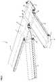
- FIG. 1is a top perspective view of a telecommunications cable management system in accordance with the present invention
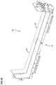
- FIG. 2is a top perspective view of a longitudinal trough member of the system of FIG. 1 ;
- FIG. 3is an end view of the trough member of FIG. 2 ;
- FIG. 4is an enlarged portion of the mating arrangement between sections of the longitudinal trough member of FIGS. 2 and 3 ;
- FIG. 5is a view similar to the view FIG. 4 , showing the sections during the mating operation;
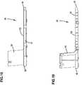
- FIG. 6is a top perspective view of one of the couplers of the system of FIG. 1 ;
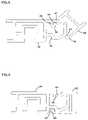
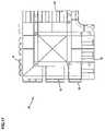
- FIG. 7is a top view of the cross component of the system of FIG. 1 ;
- FIG. 8is a side view of the cross component of FIG. 7 ;
- FIG. 9is a bottom view of the cross component of FIG. 7 ;
- FIG. 10is an enlarged portion of the view of FIG. 9 ;
- FIG. 11is a cross-sectional side view of the mating arrangement between two sections of the cross component
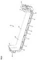
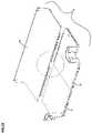
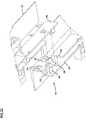
- FIG. 12is a top perspective view of the cross component of FIG. 7 showing two sections separated from the rest;
- FIG. 13is an enlarged portion of the view of FIG. 12 ;
- FIG. 14is a top perspective view of one of the sections of the cross component of FIG. 7 ;
- FIG. 15is a bottom perspective view of the section of FIG. 14 ;
- FIG. 16is a top view of the section of FIG. 14 ;
- FIG. 17is a bottom view of the section of FIG. 14 ;
- FIG. 18is a first side view of the section of FIG. 14 ;
- FIG. 19is a further side view of the section of FIG. 14 ;
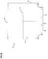
- FIG. 20is a top view of the Tee component of the system of FIG. 1 ;
- FIG. 21is a first side view of the Tee component of FIG. 20 ;
- FIG. 22is a further side view of the Tee component of FIG. 20 ;
- FIG. 23is a top perspective view of the Tee component of FIG. 20 showing one section separated from the rest;
- FIG. 24is an enlarged portion of the view of FIG. 23 ;
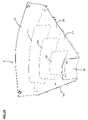
- FIG. 25is a top perspective view of the elbow component of the system of FIG. 1 ;
- FIG. 26is a top view of the elbow component of FIG. 25 ;
- FIG. 27is a side view of the elbow component of FIG. 25 ;
- FIG. 28is a top perspective view of the reducer component of the system of FIG. 1 ;
- FIG. 29is a top perspective view of an alternative embodiment of a coupler
- FIG. 30is a top perspective view of a further alternative embodiment of a coupler
- FIG. 31is a bottom perspective view of the coupler of FIG. 30 ;
- FIG. 32is an exploded perspective view of portions of the coupler FIGS. 30 and 31 ;
- FIG. 33is a first bottom perspective view of one of the sections of the coupler of FIGS. 30 and 31 ;
- FIG. 34is a further bottom perspective view of the section of FIG. 33 .
- the present inventionrelates to a cable management system with improved manufacturability and customization capabilities over prior art cable management systems.
- One aspect of the present inventionis the use of sections which are assembled into trough components which are then assembled together to form the cable management system.
- Various components and configurationsare anticipated in accordance with the present invention.
- Various examples of the components and configurationsare illustrated in FIGS. 1-34 . However, it is to be appreciated that numerous other components and configurations are possible.
- a system 10 for cable managementis positioned over a cabinet, a frame, bay or other equipment (not shown) which may include an array of connectors or other telecommunications equipment for connecting to the cables in system 10 .
- System 10is hung from the ceiling or mounted to the equipment, with various brackets and hardware.
- Example system 10includes various trough elements which together form cable pathways for holding and managing fiber optic cables.
- System 10includes longitudinal trough members 14 , and couplers 16 for joining the longitudinal trough members 14 to other trough elements including a cross component 18 , a Tee component 20 , an elbow component 22 , and a reducer 24 .
- System 10can be expanded in various directions by adding further components 14 , 16 , 18 , 20 , 22 , and 24 .
- Other arrangementsare possible for the noted components including arrangements that use less than all of the noted components, or additional components, as desired.
- a cable exit troughcan be added to allow cables to enter and exit the trough components for downward travel to equipment below trough components.
- U.S. Pat. No. 6,625,373shows an example cable exit trough mountable to lateral trough member 14 .
- longitudinal trough member 14preferably has a continuous cross-section, and can be cut to the desired length L 1 .
- Longitudinal trough member 14is preferably by an extrusion process.
- longitudinal trough member 14is made from separate sections assembled together to form longitudinal trough member 14 .
- a mating arrangement 30mounts the separate sides 32 to middle 34 .
- the mating arrangement 30includes a snap fit.
- FIGS. 4 and 5show the snap fit between one of sides 32 and middle 34 .
- mating arrangement 30includes first and second pockets 38 , 40 , which receive first and second projections 44 , 46 , respectively.
- first projection 44is inserted into first pocket 38 , and the side 32 is pivoted relative to middle 34 until second projection 46 is received in second pocket 40 to hold the side to the middle. (See FIGS. 4 and 5 ).
- First projection 44has a bent shape which fits into first pocket 38 defined by base 39 and tab 41 .
- Second projection 46is flexible outward and includes a shoulder 47 which is positioned against shoulder 43 of second pocket 40 .
- a similar mating arrangement 30mounts the other side 32 to the other side of middle 34 .
- longitudinal trough member 14can be made more easily than might be possible if the whole structure was made in a single extrusion. For example, making longitudinal trough member 14 in sizes over 12 inches across (see dimension W 1 in FIGS. 2 and 3 ), including as much as 24 inches across or more, can be difficult to mold in a single part with an extrusion. Also, different sides 32 can be mated with different middles 34 , as desired.
- Longitudinal trough member 14preferably includes structure on ends 50 for mating with other system components. As shown, longitudinal trough member 14 preferably includes attachment members 52 and pockets 54 , for mating with couplers 16 , as will be described below.
- middle 34 of longitudinal trough member 14is generally a planar shaped element.
- Sides 32have a planar bottom portion 41 , and an upstanding side portion 42 .
- upstanding side portions 42can be separate side elements mounted to planar bottom portion 41 , such as with a snap mount.
- U.S. Pat. No. 6,631,875discloses various arrangements including separate side elements. The disclosure of U.S. Pat. No. 6,631,875 is hereby incorporated by reference.
- longitudinal trough member 14defines a bottom 56 and upstanding side walls 58 for holding cables within an interior. Sufficient numbers of longitudinal trough members 14 are included in system 10 to define the appropriate cable routing pathways.
- Cross components 18 and Tee components 20allow for side exits in a horizontal direction from the longitudinal pathways defined by longitudinal trough members 14 .
- Couplers 16join longitudinal trough members 14 to cross components 18 and Tee components 20 as shown in FIG. 1 .
- Elbows 22can also be used to change the cable pathway direction between two longitudinal trough members 14 , or between a longitudinal trough member 14 and one of the cross components 18 or Tee components 20 .
- coupler 16includes at least one locking element 62 for mating with an attachment member 52 of longitudinal trough member 14 . Further details of locking of coupler 16 to longitudinal trough member 14 are described in U.S. Pat. No. 6,715,719, the disclosure of which is incorporated by reference. Other couplers can be used such as the couplers disclosed in U.S. Pat. No. 5,752,781, the disclosure of which is incorporated by reference. The couplers of U.S. Pat. No. 5,752,781 use fasteners to mount the system components. Still further couplers usable in system 10 are disclosed in U.S. Pat. Nos. 5,067,678 and 5,316,243, the disclosures of which are incorporated by reference. The system components matable with couplers 16 or other couplers may need appropriately configured mating structures, or be capable of attachment by other means to the couplers, such as by springs or fasteners, as in the prior noted patents.
- Coupler 16also includes projections 64 on both ends 66 for receipt in pockets 54 of longitudinal trough members 14 .
- Couplerdefines a bottom 68 and upstanding side walls 70 for holding cables within an interior.
- Cross component 18includes a base 82 , four upstanding side walls 84 , and four ends 86 . Ends are connectable to couplers 16 .
- Base 82 and side walls 84define cable pathways across cross component 18 .
- Side walls 84have a convexly curved shape to provide bend radius protection for the cables that may bend around within cross component 18 from one end 86 to an adjacent end 86 .
- Ends 86are mountable to couplers 16 , or other couplers configured to lock to cross component 18 .
- Cross component 18is preferably assembled from separate parts or sections 88 .
- a mating arrangement 90connects the sections 88 together.
- Each section 88includes edges 92 , 94 , 96 , 98 , a base 100 , and one side wall 84 .
- Mating arrangement 90mates edges 92 to edges 94 of adjacent sections 88 .
- Edges 96 , 98form ends 86 .
- cross component 18is made from four identical sections 88 .
- One advantage of such a constructionis that the mold for making component 18 out of moldable materials does not have to be as large as the mold would need to be to mold component 18 as a single integral part.
- Mating arrangement 90includes a shoulder 102 on edge 92 , and a flexible tab 110 on edge 94 .
- Tab 110includes an edge surface 112 which engages shoulder 102 .
- Tab 110also includes a ramp 114 for allowing tab 110 to clear shoulder 102 , so edge surface 112 can engage shoulder 102 .
- a plurality of mating shoulders 102 and tabs 110are provided along edges 92 , 94 , respectively.
- a u-shaped projection 116surrounds tab 110 .
- An enclosure 104 on edge 92surrounds projection 116 when mated. To mount one section 88 to another section 88 , edge 94 is positioned vertically above edge 92 .
- Tabs 110 and projections 116enter enclosure 104 , until edge 112 engages shoulder 102 .
- two sectionsare mated together, and two further sections are mated together, then the two mated portions are mated together by rotating the two mated portions so that the respective shoulders 102 and tabs 110 are mated between the two mated portions.
- Tee component 20is formed from two sections 88 as described above, and a longitudinal section 150 .
- Sections 88snap together as noted above.
- Sections 88snap to longitudinal section 150 with a mating arrangement 152 , including flexible tabs 110 along edge portion 192 , and shoulders 102 along edge portion 194 , of the types as noted above.
- the mated sections 88are rotated relative to longitudinal section 150 in order for the shoulders 102 and tabs 110 to be mated.
- sections 88can be used to assemble cross component 18 or Tee component 20 .
- Tee component 20has three ends, ends 86 of the type noted above, and opposite ends 154 , all of which are mountable to couplers 16 , or other couplers configured to lock to Tee component 20 .
- Elbow component 22includes a base 200 , and upstanding inner side wall 202 and outer side wall 204 . Edges 212 and 214 connect to couplers 16 . Edges 212 and 214 are at an angle to one another, such as at an angle of about 45 degrees. Such a construction allows for a change of direction of the cable pathway between components connected at each end. Two can be used for a 90 degree elbow. In the illustrated embodiment, curved guide walls or fins 206 , 208 , 210 are positioned in the interior of elbow to help guide the cables and help keep the cables from bunching up against inner side wall 202 .
- reducer component 24is shown reducing the width of the lateral trough section pathway from one dimension W 1 to a smaller dimension W 2 .
- End 220is at the wider dimension W 1 , such as 24 inches, and opposite end 222 is at the narrower dimension W 2 , such as 12 inches.
- Reducer component 24is mountable to couplers 16 , or other couplers configured to lock to cross component 18 .
- FIG. 29and alternative embodiment of a coupler 260 is shown with guide tabs 262 protruding from projections 64 .
- Guide tabs 262assist with locating projections 62 in the pockets of longitudinal trough members 14 during assembly of the system.
- Coupler 360is provided in two sections 362 , 364 , which are preferably identical.
- a mating arrangement 370mounts the two sections 362 , 364 together.
- One preferred embodiment of mating arrangement 370includes snaps.
- Each section 362 , 364includes first and second walls 372 , 374 offset from one another.
- First wall 372includes first tabs 380 with shoulders 382 , and an aperture 384 .
- Second wall 374includes second tabs 390 with shoulders 392 , and an aperture 394 .
- the first tabs 380 of each wall 372fit into the aperture 384 of the other wall 372 of the other section.
- each wall 374fits into the aperture 394 of the other wall 374 of the other section. Further cutouts 396 , 398 are also matable together when mounting the sections together.
Landscapes
- Engineering & Computer Science (AREA)
- Architecture (AREA)
- Civil Engineering (AREA)
- Structural Engineering (AREA)
- Physics & Mathematics (AREA)
- General Physics & Mathematics (AREA)
- Optics & Photonics (AREA)
- Laying Of Electric Cables Or Lines Outside (AREA)
- Installation Of Indoor Wiring (AREA)
- Connector Housings Or Holding Contact Members (AREA)
- Details Of Indoor Wiring (AREA)
Abstract
Description
Claims (8)
Priority Applications (3)
| Application Number | Priority Date | Filing Date | Title |
|---|---|---|---|
| US12/275,979US7668433B2 (en) | 2005-10-07 | 2008-11-21 | Cable trough system and method |
| US12/705,849US8965167B2 (en) | 2005-10-07 | 2010-02-15 | Cable trough system and method |
| US14/601,581US9356436B2 (en) | 2005-10-07 | 2015-01-21 | Cable trough system and method |
Applications Claiming Priority (2)
| Application Number | Priority Date | Filing Date | Title |
|---|---|---|---|
| US11/246,003US7471868B2 (en) | 2005-10-07 | 2005-10-07 | Cable trough system and method |
| US12/275,979US7668433B2 (en) | 2005-10-07 | 2008-11-21 | Cable trough system and method |
Related Parent Applications (1)
| Application Number | Title | Priority Date | Filing Date |
|---|---|---|---|
| US11/246,003ContinuationUS7471868B2 (en) | 2005-10-07 | 2005-10-07 | Cable trough system and method |
Related Child Applications (1)
| Application Number | Title | Priority Date | Filing Date |
|---|---|---|---|
| US12/705,849ContinuationUS8965167B2 (en) | 2005-10-07 | 2010-02-15 | Cable trough system and method |
Publications (2)
| Publication Number | Publication Date |
|---|---|
| US20090158578A1 US20090158578A1 (en) | 2009-06-25 |
| US7668433B2true US7668433B2 (en) | 2010-02-23 |
Family
ID=37631254
Family Applications (5)
| Application Number | Title | Priority Date | Filing Date |
|---|---|---|---|
| US11/246,003Expired - LifetimeUS7471868B2 (en) | 2005-10-07 | 2005-10-07 | Cable trough system and method |
| US29/328,318Expired - LifetimeUSD609192S1 (en) | 2005-10-07 | 2008-11-21 | Fiber trough horizontal cross component |
| US12/275,979Expired - Fee RelatedUS7668433B2 (en) | 2005-10-07 | 2008-11-21 | Cable trough system and method |
| US12/705,849Active2028-11-30US8965167B2 (en) | 2005-10-07 | 2010-02-15 | Cable trough system and method |
| US14/601,581Expired - LifetimeUS9356436B2 (en) | 2005-10-07 | 2015-01-21 | Cable trough system and method |
Family Applications Before (2)
| Application Number | Title | Priority Date | Filing Date |
|---|---|---|---|
| US11/246,003Expired - LifetimeUS7471868B2 (en) | 2005-10-07 | 2005-10-07 | Cable trough system and method |
| US29/328,318Expired - LifetimeUSD609192S1 (en) | 2005-10-07 | 2008-11-21 | Fiber trough horizontal cross component |
Family Applications After (2)
| Application Number | Title | Priority Date | Filing Date |
|---|---|---|---|
| US12/705,849Active2028-11-30US8965167B2 (en) | 2005-10-07 | 2010-02-15 | Cable trough system and method |
| US14/601,581Expired - LifetimeUS9356436B2 (en) | 2005-10-07 | 2015-01-21 | Cable trough system and method |
Country Status (8)
| Country | Link |
|---|---|
| US (5) | US7471868B2 (en) |
| EP (1) | EP1932225A1 (en) |
| KR (1) | KR101280647B1 (en) |
| CN (2) | CN101283494B (en) |
| AU (2) | AU2006302511B2 (en) |
| BR (1) | BRPI0616988A2 (en) |
| CA (1) | CA2620871C (en) |
| WO (1) | WO2007044338A1 (en) |
Cited By (41)
| Publication number | Priority date | Publication date | Assignee | Title |
|---|---|---|---|---|
| US20080203240A1 (en)* | 2007-01-19 | 2008-08-28 | Mark Smrha | Lateral storage spool for overhead cable pathway |
| US20100142911A1 (en)* | 2005-10-07 | 2010-06-10 | Adc Telecommunications, Inc. | Cable Trough System and Method |
| US20100220967A1 (en)* | 2009-02-27 | 2010-09-02 | Cooke Terry L | Hinged Fiber Optic Module Housing and Module |
| US20110268411A1 (en)* | 2010-04-30 | 2011-11-03 | Giraud William J | Fiber optic housings configured for tool-less assembly, and related components and methods |
| US8538226B2 (en) | 2009-05-21 | 2013-09-17 | Corning Cable Systems Llc | Fiber optic equipment guides and rails configured with stopping position(s), and related equipment and methods |
| US8542973B2 (en) | 2010-04-23 | 2013-09-24 | Ccs Technology, Inc. | Fiber optic distribution device |
| US8593828B2 (en) | 2010-02-04 | 2013-11-26 | Corning Cable Systems Llc | Communications equipment housings, assemblies, and related alignment features and methods |
| US8625950B2 (en) | 2009-12-18 | 2014-01-07 | Corning Cable Systems Llc | Rotary locking apparatus for fiber optic equipment trays and related methods |
| US8660397B2 (en) | 2010-04-30 | 2014-02-25 | Corning Cable Systems Llc | Multi-layer module |
| US8662760B2 (en) | 2010-10-29 | 2014-03-04 | Corning Cable Systems Llc | Fiber optic connector employing optical fiber guide member |
| US8699838B2 (en) | 2009-05-14 | 2014-04-15 | Ccs Technology, Inc. | Fiber optic furcation module |
| US8705926B2 (en) | 2010-04-30 | 2014-04-22 | Corning Optical Communications LLC | Fiber optic housings having a removable top, and related components and methods |
| US8712206B2 (en) | 2009-06-19 | 2014-04-29 | Corning Cable Systems Llc | High-density fiber optic modules and module housings and related equipment |
| US8718436B2 (en) | 2010-08-30 | 2014-05-06 | Corning Cable Systems Llc | Methods, apparatuses for providing secure fiber optic connections |
| US8879881B2 (en) | 2010-04-30 | 2014-11-04 | Corning Cable Systems Llc | Rotatable routing guide and assembly |
| US8913866B2 (en) | 2010-03-26 | 2014-12-16 | Corning Cable Systems Llc | Movable adapter panel |
| US8953924B2 (en) | 2011-09-02 | 2015-02-10 | Corning Cable Systems Llc | Removable strain relief brackets for securing fiber optic cables and/or optical fibers to fiber optic equipment, and related assemblies and methods |
| US8965168B2 (en) | 2010-04-30 | 2015-02-24 | Corning Cable Systems Llc | Fiber management devices for fiber optic housings, and related components and methods |
| US8989547B2 (en) | 2011-06-30 | 2015-03-24 | Corning Cable Systems Llc | Fiber optic equipment assemblies employing non-U-width-sized housings and related methods |
| US8985862B2 (en) | 2013-02-28 | 2015-03-24 | Corning Cable Systems Llc | High-density multi-fiber adapter housings |
| US8995812B2 (en) | 2012-10-26 | 2015-03-31 | Ccs Technology, Inc. | Fiber optic management unit and fiber optic distribution device |
| US9008485B2 (en) | 2011-05-09 | 2015-04-14 | Corning Cable Systems Llc | Attachment mechanisms employed to attach a rear housing section to a fiber optic housing, and related assemblies and methods |
| US9020320B2 (en) | 2008-08-29 | 2015-04-28 | Corning Cable Systems Llc | High density and bandwidth fiber optic apparatuses and related equipment and methods |
| US9022814B2 (en) | 2010-04-16 | 2015-05-05 | Ccs Technology, Inc. | Sealing and strain relief device for data cables |
| US9038832B2 (en) | 2011-11-30 | 2015-05-26 | Corning Cable Systems Llc | Adapter panel support assembly |
| US9042702B2 (en) | 2012-09-18 | 2015-05-26 | Corning Cable Systems Llc | Platforms and systems for fiber optic cable attachment |
| US9059578B2 (en) | 2009-02-24 | 2015-06-16 | Ccs Technology, Inc. | Holding device for a cable or an assembly for use with a cable |
| US9075217B2 (en) | 2010-04-30 | 2015-07-07 | Corning Cable Systems Llc | Apparatuses and related components and methods for expanding capacity of fiber optic housings |
| US9116324B2 (en) | 2010-10-29 | 2015-08-25 | Corning Cable Systems Llc | Stacked fiber optic modules and fiber optic equipment configured to support stacked fiber optic modules |
| US9213161B2 (en) | 2010-11-05 | 2015-12-15 | Corning Cable Systems Llc | Fiber body holder and strain relief device |
| US9250409B2 (en) | 2012-07-02 | 2016-02-02 | Corning Cable Systems Llc | Fiber-optic-module trays and drawers for fiber-optic equipment |
| US9279951B2 (en) | 2010-10-27 | 2016-03-08 | Corning Cable Systems Llc | Fiber optic module for limited space applications having a partially sealed module sub-assembly |
| US9519118B2 (en) | 2010-04-30 | 2016-12-13 | Corning Optical Communications LLC | Removable fiber management sections for fiber optic housings, and related components and methods |
| US9645317B2 (en) | 2011-02-02 | 2017-05-09 | Corning Optical Communications LLC | Optical backplane extension modules, and related assemblies suitable for establishing optical connections to information processing modules disposed in equipment racks |
| US9720195B2 (en) | 2010-04-30 | 2017-08-01 | Corning Optical Communications LLC | Apparatuses and related components and methods for attachment and release of fiber optic housings to and from an equipment rack |
| US10094996B2 (en) | 2008-08-29 | 2018-10-09 | Corning Optical Communications, Llc | Independently translatable modules and fiber optic equipment trays in fiber optic equipment |
| USD868004S1 (en) | 2018-04-25 | 2019-11-26 | Telect, Inc. | Cable trough lip |
| USD887992S1 (en) | 2018-04-25 | 2020-06-23 | Telect, Inc. | Cable trough attachment assembly |
| US11294136B2 (en) | 2008-08-29 | 2022-04-05 | Corning Optical Communications LLC | High density and bandwidth fiber optic apparatuses and related equipment and methods |
| US11646556B2 (en) | 2019-10-17 | 2023-05-09 | Panduit Corp. | Raceway system |
| US11784475B2 (en) | 2021-01-12 | 2023-10-10 | Panduit Corp. | Intersection system for overhead cable trays |
Families Citing this family (23)
| Publication number | Priority date | Publication date | Assignee | Title |
|---|---|---|---|---|
| US6631875B1 (en)* | 2000-09-26 | 2003-10-14 | Adc Telecommunications, Inc. | Cable trough with separate side elements |
| USD577684S1 (en) | 2007-01-26 | 2008-09-30 | Adc Telecommunications, Inc. | Fiber trough snaps |
| USD576108S1 (en) | 2007-01-26 | 2008-09-02 | Adc Telecommunications, Inc. | Fiber trough horizontal T component |
| USD576107S1 (en) | 2007-01-26 | 2008-09-02 | Adc Telecommunications, Inc. | Fiber trough lateral component |
| USD576559S1 (en) | 2007-01-26 | 2008-09-09 | Adc Telecommunications, Inc. | Fiber trough horizontal T component |
| USD576106S1 (en) | 2007-01-26 | 2008-09-02 | Adc Telecommunications, Inc. | Fiber trough lateral component |
| USD576109S1 (en) | 2007-01-26 | 2008-09-02 | Adc Telecommunications, Inc. | Fiber trough base |
| USD576560S1 (en) | 2007-01-26 | 2008-09-09 | Adc Telecommunications, Inc. | Fiber trough horizontal T component |
| US7742675B2 (en)* | 2007-01-26 | 2010-06-22 | Adc Telecommunications, Inc. | Cable trough system and method |
| USD576956S1 (en) | 2007-01-26 | 2008-09-16 | Adc Telecommunications, Inc. | Fiber trough base |
| US7627224B1 (en)* | 2008-12-24 | 2009-12-01 | At&T Intellectual Property I, L.P. | Cabinet fiber manager |
| GB0901544D0 (en)* | 2009-01-30 | 2009-03-11 | Trojan Services Ltd | A combined cable trough and walkway |
| DE102009017319A1 (en)* | 2009-04-16 | 2010-10-21 | Airbus Deutschland Gmbh | Cable management device for an electrical wiring harness laid in an aircraft cabin |
| NL1037529C2 (en)* | 2009-12-04 | 2011-06-07 | Arend Jan Vliet | SYSTEM FOR THE REALIZATION OF A CABLE TRAY AND DIVIDING WALLS, COUPLING PLATES AND CLIPS AS PART OF THIS SYSTEM. |
| US8785779B1 (en)* | 2012-02-06 | 2014-07-22 | The Boeing Company | Snap-in raceway |
| TW201434225A (en)* | 2013-02-27 | 2014-09-01 | wen-zhong Zhuang | Easily assembled grooves set |
| DE202014103562U1 (en)* | 2014-07-31 | 2014-09-11 | Igus Gmbh | guide means |
| WO2018081415A1 (en) | 2016-10-27 | 2018-05-03 | Steelcase Inc. | Flip top table |
| US20190331260A1 (en)* | 2018-04-25 | 2019-10-31 | Telect, Inc. | Cable Trough System |
| CN110429535A (en)* | 2019-08-20 | 2019-11-08 | 福建省顺安建筑工程有限公司 | Cabling decorative groove for building and its assembly method |
| BR102020005429A2 (en)* | 2020-03-18 | 2021-09-28 | Flávio Albertini Diaferia | IMPROVEMENTS IN SET OF MODULAR BEDS FOR STRUCTURED FIBER OPTIC WIRING |
| DE102020119796A1 (en) | 2020-07-28 | 2022-02-03 | Frank Beteiligungsgesellschaft Mbh | cable tray element |
| WO2024039695A1 (en)* | 2022-08-16 | 2024-02-22 | Ppc Broadband, Inc. | Modular and scalable optical fiber cable fixation, entry, storage, and splicing system providing expandability on demand |
Citations (53)
| Publication number | Priority date | Publication date | Assignee | Title |
|---|---|---|---|---|
| US799320A (en) | 1904-02-09 | 1905-09-12 | Orrin G Franks | Metal column, girder, and beam. |
| DE1130492B (en) | 1959-07-28 | 1962-05-30 | Ursus Kunststoff G M B H | Conduit |
| US3351699A (en) | 1965-03-19 | 1967-11-07 | Danzer Metal Works Co | Raceway for electrical cables and wires adapted to retain rf energy |
| US3761603A (en) | 1972-11-14 | 1973-09-25 | Amp Inc | Wiring raceway |
| FR2238828A1 (en) | 1973-07-24 | 1975-02-21 | Intermercury Finance Trading C | |
| US4077434A (en) | 1976-05-27 | 1978-03-07 | Federal Cartridge Corporation | Sealed lay-in conduit duct |
| SU1272387A1 (en) | 1979-03-11 | 1986-11-23 | Государственный Проектный Институт "Электропроект" | Collapsible duct for laying wires and cables |
| DE3742448A1 (en) | 1987-12-15 | 1989-06-29 | Philips Patentverwaltung | Cable duct |
| US4907767A (en) | 1988-08-12 | 1990-03-13 | Hubbell Incorporated | Stackable modular duct assemblies |
| US4951716A (en) | 1987-12-17 | 1990-08-28 | Yazaki Corporation | Locking mechanism |
| USD321682S (en) | 1989-07-31 | 1991-11-19 | Roy Henneberger | Guiding through, 90 degree down elbow for optical fibers |
| US5067678A (en) | 1989-07-31 | 1991-11-26 | Adc Telecommunications, Inc. | Optic cable management system |
| USD321862S (en) | 1989-07-31 | 1991-11-26 | Roy Henneberger | Guiding trough, horizontal T for optical fibers |
| US5160811A (en) | 1990-04-27 | 1992-11-03 | Tyton Corporation | Duct transition converter and flexible connectors including same |
| US5161580A (en) | 1990-08-27 | 1992-11-10 | Tyton Corporation | Cable duct fitting with removable cover |
| JPH05172281A (en) | 1991-12-25 | 1993-07-09 | Ee O Y Syst Kenkyusho:Kk | Duct assembling method and seam joint structure of duct |
| US5240209A (en) | 1992-11-17 | 1993-08-31 | Telect, Inc. | Telecommunication multiple cable carrier |
| US5271585A (en) | 1990-10-01 | 1993-12-21 | Zetena Jr Maurice F | Modular fiber optics raceway permitting flexible installation |
| US5316243A (en) | 1989-07-31 | 1994-05-31 | Adc Telecommunications, Inc. | Optic cable management |
| US5335349A (en) | 1992-12-14 | 1994-08-02 | Telect, Inc. | Telecommunication overhead cable distribution assembly |
| US5469893A (en) | 1993-12-21 | 1995-11-28 | Panduit Corp. | Tab and slot fiber optic fitting |
| US5503354A (en) | 1994-01-04 | 1996-04-02 | Telect, Inc. | Telecommunication overhead cable distribution universal support bracket |
| DE29610947U1 (en) | 1996-06-24 | 1996-08-22 | Miranda, Giovanni, 78549 Spaichingen | Cable duct profile |
| FR2735557A1 (en) | 1995-06-14 | 1996-12-20 | Seine Const Elec | Coupling for `U' sections cable troughs |
| US5753855A (en) | 1994-11-17 | 1998-05-19 | Panduit Corp. | Wiring duct fittings |
| US5752781A (en) | 1997-03-14 | 1998-05-19 | Adc Telecommunications, Inc. | Fiber trough coupling |
| EP0863594A2 (en) | 1997-03-06 | 1998-09-09 | Albert Ackermann GmbH & Co. KG | Electrical installation channel |
| US5899025A (en) | 1996-03-22 | 1999-05-04 | Steelcase Inc. | Furniture system (pathways-spaceframe) |
| US5923753A (en) | 1997-11-17 | 1999-07-13 | Adc Telecommunications, Inc. | Optic cable exit trough with bypass |
| EP0933850A1 (en) | 1998-01-27 | 1999-08-04 | Placo S.r.l. | A modular ducting device |
| US5937131A (en) | 1997-11-17 | 1999-08-10 | Adc Telecommunications, Inc. | Optical cable exit trough |
| US5995699A (en) | 1998-01-05 | 1999-11-30 | The Wiremold Company | Fiber optic cable raceway system cross reference to related applications |
| US6037543A (en) | 1994-11-17 | 2000-03-14 | Panduit Corp. | Wiring duct fittings |
| US6037538A (en) | 1997-04-28 | 2000-03-14 | Brooks; Gary Douglas | Cable raceway |
| US6076779A (en) | 1999-08-04 | 2000-06-20 | Adc Telecommunications, Inc. | Cable guiding trough |
| US6198047B1 (en) | 1999-02-08 | 2001-03-06 | Charles Barr | Cable tray with power channel |
| US20020096606A1 (en) | 2000-06-01 | 2002-07-25 | Bernard William A. | Cable duct coupler |
| US6450458B1 (en) | 2000-06-01 | 2002-09-17 | Panduit Corp. | Cable duct coupler with locking clip |
| US6522823B1 (en) | 2000-11-06 | 2003-02-18 | Adc Telecommunications, Inc. | Low profile cable exit trough |
| US20030047343A1 (en) | 2001-09-12 | 2003-03-13 | Ferris Matthew D. | Snap together cable trough system |
| US6535683B1 (en) | 2000-10-06 | 2003-03-18 | Adc Telecommunications, Inc. | Cable exit trough with cover |
| US6559378B1 (en) | 2001-10-31 | 2003-05-06 | Panduit Corp. | Reducer fitting for routing system |
| US6625373B1 (en) | 2000-10-06 | 2003-09-23 | Adc Telecommunications, Inc. | Cable exit trough with insert |
| US6631875B1 (en) | 2000-09-26 | 2003-10-14 | Adc Telecommunications, Inc. | Cable trough with separate side elements |
| US6634805B1 (en) | 2001-10-10 | 2003-10-21 | Advanced Micro Devices, Inc. | Parallel plate development |
| US6709186B2 (en) | 2001-11-16 | 2004-03-23 | Adc Telecommunications, Inc. | Coupler for cable trough |
| US6708918B2 (en) | 2001-03-01 | 2004-03-23 | Adc Telecommunications, Inc. | Cable guiding fins |
| US6715719B2 (en) | 2002-03-27 | 2004-04-06 | Adc Telecommunications, Inc. | Coupler for cable trough |
| US6727434B2 (en) | 2001-07-13 | 2004-04-27 | Legrand | Accessory for trunking comprising lengths of trunking with different heights |
| US6739795B1 (en) | 2000-05-25 | 2004-05-25 | Adc Telecommunications, Inc. | Telescoping trough |
| US7034227B2 (en) | 2002-08-19 | 2006-04-25 | Fox Ron W | Cable trough |
| US7045707B1 (en) | 2005-03-07 | 2006-05-16 | The Wiremold Company | Surface mounted perimeter raceway offset assembly |
| US20080181568A1 (en)* | 2007-01-26 | 2008-07-31 | Derek Sayres | Cable trough system and method |
Family Cites Families (24)
| Publication number | Priority date | Publication date | Assignee | Title |
|---|---|---|---|---|
| US3035800A (en) | 1959-11-24 | 1962-05-22 | Burndy Corp | Cable tray accessories |
| DE2336132A1 (en)* | 1973-07-16 | 1975-02-06 | Siemens Ag | DEVICE FOR PHASE CONTROL |
| US4234760A (en)* | 1978-12-18 | 1980-11-18 | Amp Incorporated | Covering for T-tap terminals |
| USD278229S (en) | 1982-12-17 | 1985-04-02 | Jan Widell | Collector rail |
| USD320782S (en) | 1989-07-31 | 1991-10-15 | Roy Henneberger | Guiding trough downspout for optical fibers |
| USD322596S (en) | 1989-07-31 | 1991-12-24 | Roy Henneberger | Guiding trough for optical fibers |
| USD320976S (en) | 1989-07-31 | 1991-10-22 | Roy Henneberger | Guiding trough, straight reducing adapter for optical fibers |
| JPH06284544A (en)* | 1993-03-31 | 1994-10-07 | Idemitsu Petrochem Co Ltd | Trough made of synthetic resin |
| CN2183625Y (en)* | 1994-01-21 | 1994-11-23 | 曹荣 | Split full-insulation power transmission bustar channel device |
| US5715099A (en) | 1994-04-28 | 1998-02-03 | Ricoh Company, Ltd. | Mounting method and structure for a solid-state image pickup element in an image reading-out apparatus |
| USD415471S (en) | 1998-07-22 | 1999-10-19 | Henry Stephen K | Modular cable protector |
| USD402262S (en) | 1996-12-06 | 1998-12-08 | Panduit Corp. | Straight dual raceway fitting |
| KR19980064789U (en)* | 1997-04-30 | 1998-11-25 | 윤정 | Cable trough |
| CN2307386Y (en)* | 1997-09-10 | 1999-02-10 | 南通金洋兴旺集团有限公司 | Corrosion-resisting steel cable bridge |
| USD413306S (en)* | 1998-06-04 | 1999-08-31 | Panduit Corp. | Right angle single raceway fitting |
| US6284975B1 (en)* | 1999-06-16 | 2001-09-04 | The Wiremold Company | Divider for raceway tee assembly |
| KR200173081Y1 (en) | 1999-09-20 | 2000-03-15 | 전안수 | Cable trough |
| US6437244B1 (en) | 2000-06-05 | 2002-08-20 | Panduit Corp. | Wiring duct system hinge arrangement |
| JP3961234B2 (en)* | 2001-04-27 | 2007-08-22 | 矢崎総業株式会社 | Locking structure |
| JP2003029082A (en)* | 2001-07-13 | 2003-01-29 | Ntt Advanced Technology Corp | Optical fiber coupler storage member |
| US6810191B2 (en)* | 2001-07-20 | 2004-10-26 | Adc Telecommunications, Inc. | Cable trough cover |
| MXPA04009279A (en)* | 2002-03-27 | 2005-01-25 | Adc Telecommunications Inc | Coupler for cable trough. |
| US7471868B2 (en) | 2005-10-07 | 2008-12-30 | Adc Telecommunications, Inc. | Cable trough system and method |
| US7896295B2 (en)* | 2007-02-21 | 2011-03-01 | Adc Telecommunications, Inc. | Coupler for cable trough |
- 2005
- 2005-10-07USUS11/246,003patent/US7471868B2/ennot_activeExpired - Lifetime
- 2006
- 2006-09-29EPEP06816134Apatent/EP1932225A1/ennot_activeWithdrawn
- 2006-09-29WOPCT/US2006/038648patent/WO2007044338A1/enactiveApplication Filing
- 2006-09-29AUAU2006302511Apatent/AU2006302511B2/ennot_activeCeased
- 2006-09-29CNCN2006800371005Apatent/CN101283494B/ennot_activeExpired - Fee Related
- 2006-09-29CACA2620871Apatent/CA2620871C/ennot_activeExpired - Fee Related
- 2006-09-29KRKR1020087011017Apatent/KR101280647B1/ennot_activeExpired - Fee Related
- 2006-09-29BRBRPI0616988-0Apatent/BRPI0616988A2/ennot_activeIP Right Cessation
- 2006-09-29CNCN2011100061425Apatent/CN102163825B/ennot_activeExpired - Fee Related
- 2008
- 2008-11-21USUS29/328,318patent/USD609192S1/ennot_activeExpired - Lifetime
- 2008-11-21USUS12/275,979patent/US7668433B2/ennot_activeExpired - Fee Related
- 2010
- 2010-02-15USUS12/705,849patent/US8965167B2/enactiveActive
- 2010-12-21AUAU2010257337Apatent/AU2010257337B2/ennot_activeCeased
- 2015
- 2015-01-21USUS14/601,581patent/US9356436B2/ennot_activeExpired - Lifetime
Patent Citations (57)
| Publication number | Priority date | Publication date | Assignee | Title |
|---|---|---|---|---|
| US799320A (en) | 1904-02-09 | 1905-09-12 | Orrin G Franks | Metal column, girder, and beam. |
| DE1130492B (en) | 1959-07-28 | 1962-05-30 | Ursus Kunststoff G M B H | Conduit |
| US3351699A (en) | 1965-03-19 | 1967-11-07 | Danzer Metal Works Co | Raceway for electrical cables and wires adapted to retain rf energy |
| US3761603A (en) | 1972-11-14 | 1973-09-25 | Amp Inc | Wiring raceway |
| FR2238828A1 (en) | 1973-07-24 | 1975-02-21 | Intermercury Finance Trading C | |
| US3927698A (en) | 1973-07-24 | 1975-12-23 | Intermercury Finance & Trad | Installation channel |
| US4077434A (en) | 1976-05-27 | 1978-03-07 | Federal Cartridge Corporation | Sealed lay-in conduit duct |
| SU1272387A1 (en) | 1979-03-11 | 1986-11-23 | Государственный Проектный Институт "Электропроект" | Collapsible duct for laying wires and cables |
| DE3742448A1 (en) | 1987-12-15 | 1989-06-29 | Philips Patentverwaltung | Cable duct |
| US4951716A (en) | 1987-12-17 | 1990-08-28 | Yazaki Corporation | Locking mechanism |
| US4907767A (en) | 1988-08-12 | 1990-03-13 | Hubbell Incorporated | Stackable modular duct assemblies |
| USD321682S (en) | 1989-07-31 | 1991-11-19 | Roy Henneberger | Guiding through, 90 degree down elbow for optical fibers |
| US5067678A (en) | 1989-07-31 | 1991-11-26 | Adc Telecommunications, Inc. | Optic cable management system |
| USD321862S (en) | 1989-07-31 | 1991-11-26 | Roy Henneberger | Guiding trough, horizontal T for optical fibers |
| US5316243A (en) | 1989-07-31 | 1994-05-31 | Adc Telecommunications, Inc. | Optic cable management |
| US5160811A (en) | 1990-04-27 | 1992-11-03 | Tyton Corporation | Duct transition converter and flexible connectors including same |
| US5161580A (en) | 1990-08-27 | 1992-11-10 | Tyton Corporation | Cable duct fitting with removable cover |
| US5271585A (en) | 1990-10-01 | 1993-12-21 | Zetena Jr Maurice F | Modular fiber optics raceway permitting flexible installation |
| US5316244A (en) | 1990-10-01 | 1994-05-31 | Zetena Jr Maurice F | Supporting brackets for cable raceways |
| JPH05172281A (en) | 1991-12-25 | 1993-07-09 | Ee O Y Syst Kenkyusho:Kk | Duct assembling method and seam joint structure of duct |
| US5240209A (en) | 1992-11-17 | 1993-08-31 | Telect, Inc. | Telecommunication multiple cable carrier |
| US5335349A (en) | 1992-12-14 | 1994-08-02 | Telect, Inc. | Telecommunication overhead cable distribution assembly |
| US5469893A (en) | 1993-12-21 | 1995-11-28 | Panduit Corp. | Tab and slot fiber optic fitting |
| US5503354A (en) | 1994-01-04 | 1996-04-02 | Telect, Inc. | Telecommunication overhead cable distribution universal support bracket |
| US5753855A (en) | 1994-11-17 | 1998-05-19 | Panduit Corp. | Wiring duct fittings |
| US6037543A (en) | 1994-11-17 | 2000-03-14 | Panduit Corp. | Wiring duct fittings |
| FR2735557A1 (en) | 1995-06-14 | 1996-12-20 | Seine Const Elec | Coupling for `U' sections cable troughs |
| US5899025A (en) | 1996-03-22 | 1999-05-04 | Steelcase Inc. | Furniture system (pathways-spaceframe) |
| DE29610947U1 (en) | 1996-06-24 | 1996-08-22 | Miranda, Giovanni, 78549 Spaichingen | Cable duct profile |
| US6107575A (en) | 1996-06-24 | 2000-08-22 | Hilti Aktiengesellschaft | Cable channel section |
| EP0863594A2 (en) | 1997-03-06 | 1998-09-09 | Albert Ackermann GmbH & Co. KG | Electrical installation channel |
| US5752781A (en) | 1997-03-14 | 1998-05-19 | Adc Telecommunications, Inc. | Fiber trough coupling |
| US6037538A (en) | 1997-04-28 | 2000-03-14 | Brooks; Gary Douglas | Cable raceway |
| US5923753A (en) | 1997-11-17 | 1999-07-13 | Adc Telecommunications, Inc. | Optic cable exit trough with bypass |
| US5937131A (en) | 1997-11-17 | 1999-08-10 | Adc Telecommunications, Inc. | Optical cable exit trough |
| US5995699A (en) | 1998-01-05 | 1999-11-30 | The Wiremold Company | Fiber optic cable raceway system cross reference to related applications |
| EP0933850A1 (en) | 1998-01-27 | 1999-08-04 | Placo S.r.l. | A modular ducting device |
| US6198047B1 (en) | 1999-02-08 | 2001-03-06 | Charles Barr | Cable tray with power channel |
| US6076779A (en) | 1999-08-04 | 2000-06-20 | Adc Telecommunications, Inc. | Cable guiding trough |
| US6739795B1 (en) | 2000-05-25 | 2004-05-25 | Adc Telecommunications, Inc. | Telescoping trough |
| US20020096606A1 (en) | 2000-06-01 | 2002-07-25 | Bernard William A. | Cable duct coupler |
| US6450458B1 (en) | 2000-06-01 | 2002-09-17 | Panduit Corp. | Cable duct coupler with locking clip |
| US6631875B1 (en) | 2000-09-26 | 2003-10-14 | Adc Telecommunications, Inc. | Cable trough with separate side elements |
| US20040124321A1 (en) | 2000-09-26 | 2004-07-01 | Adc Telecommunications Inc. | Cable trough method with separate side elements |
| US6535683B1 (en) | 2000-10-06 | 2003-03-18 | Adc Telecommunications, Inc. | Cable exit trough with cover |
| US6625373B1 (en) | 2000-10-06 | 2003-09-23 | Adc Telecommunications, Inc. | Cable exit trough with insert |
| US6522823B1 (en) | 2000-11-06 | 2003-02-18 | Adc Telecommunications, Inc. | Low profile cable exit trough |
| US6708918B2 (en) | 2001-03-01 | 2004-03-23 | Adc Telecommunications, Inc. | Cable guiding fins |
| US6727434B2 (en) | 2001-07-13 | 2004-04-27 | Legrand | Accessory for trunking comprising lengths of trunking with different heights |
| US20030047343A1 (en) | 2001-09-12 | 2003-03-13 | Ferris Matthew D. | Snap together cable trough system |
| US6634805B1 (en) | 2001-10-10 | 2003-10-21 | Advanced Micro Devices, Inc. | Parallel plate development |
| US6559378B1 (en) | 2001-10-31 | 2003-05-06 | Panduit Corp. | Reducer fitting for routing system |
| US6709186B2 (en) | 2001-11-16 | 2004-03-23 | Adc Telecommunications, Inc. | Coupler for cable trough |
| US6715719B2 (en) | 2002-03-27 | 2004-04-06 | Adc Telecommunications, Inc. | Coupler for cable trough |
| US7034227B2 (en) | 2002-08-19 | 2006-04-25 | Fox Ron W | Cable trough |
| US7045707B1 (en) | 2005-03-07 | 2006-05-16 | The Wiremold Company | Surface mounted perimeter raceway offset assembly |
| US20080181568A1 (en)* | 2007-01-26 | 2008-07-31 | Derek Sayres | Cable trough system and method |
Non-Patent Citations (14)
| Title |
|---|
| ADC Telecommunications brochure entitled "ADC FiberGuide� System Express Exit(TM) 2�2," 2 pages, dated May 1999. |
| ADC Telecommunications brochure entitled "ADC FiberGuide® System Express Exit™ 2×2," 2 pages, dated May 1999. |
| ADC Telecommunications brochure entitled "Fiber Guide(TM) Fiber Management System," 6 pages, dated Jun. 1989. |
| ADC Telecommunications brochure entitled "Fiber Guide™ Fiber Management System," 6 pages, dated Jun. 1989. |
| ADC Telecommunications brochure entitled "FiberGuide� Fiber Management Systems," 33 pages, dated Oct. 1995. |
| ADC Telecommunications brochure entitled "FiberGuide� Fiber Management Systems," 37 pages, dated Jun. 1998. |
| ADC Telecommunications brochure entitled "FiberGuide® Fiber Management Systems," 33 pages, dated Oct. 1995. |
| ADC Telecommunications brochure entitled "FiberGuide® Fiber Management Systems," 37 pages, dated Jun. 1998. |
| ADC Telecommunications brochure entitled FiberGuide� Fiber Management Systems, 56 pages, dated Sep. 2000. |
| ADC Telecommunications brochure entitled FiberGuide� Fiber Management Systems, 90 pages, dated May 2005. |
| ADC Telecommunications brochure entitled FiberGuide® Fiber Management Systems, 56 pages, dated Sep. 2000. |
| ADC Telecommunications brochure entitled FiberGuide® Fiber Management Systems, 90 pages, dated May 2005. |
| International Search Report mailed Jan. 29, 2007 (PCT/US2006/038648). |
| Warren & Brown & Staff brochure pages entitled "lightpaths," Issue 2, 11 pages, dated 1995. |
Cited By (67)
| Publication number | Priority date | Publication date | Assignee | Title |
|---|---|---|---|---|
| US8965167B2 (en)* | 2005-10-07 | 2015-02-24 | Adc Telecommunications, Inc. | Cable trough system and method |
| US20100142911A1 (en)* | 2005-10-07 | 2010-06-10 | Adc Telecommunications, Inc. | Cable Trough System and Method |
| US9356436B2 (en) | 2005-10-07 | 2016-05-31 | Commscope Technologies Llc | Cable trough system and method |
| US20080203240A1 (en)* | 2007-01-19 | 2008-08-28 | Mark Smrha | Lateral storage spool for overhead cable pathway |
| US8070112B2 (en)* | 2007-01-19 | 2011-12-06 | Adc Telecommunications, Inc. | Lateral storage spool for overhead cable pathway |
| US20120032034A1 (en)* | 2007-01-19 | 2012-02-09 | Adc Telecommunications, Inc. | Lateral storage spool for overhead cable pathway |
| US8376288B2 (en)* | 2007-01-19 | 2013-02-19 | Adc Telecommunications, Inc. | Lateral storage spool for overhead cable pathway |
| US11754796B2 (en) | 2008-08-29 | 2023-09-12 | Corning Optical Communications LLC | Independently translatable modules and fiber optic equipment trays in fiber optic equipment |
| US10126514B2 (en) | 2008-08-29 | 2018-11-13 | Corning Optical Communications, Llc | Independently translatable modules and fiber optic equipment trays in fiber optic equipment |
| US11294135B2 (en) | 2008-08-29 | 2022-04-05 | Corning Optical Communications LLC | High density and bandwidth fiber optic apparatuses and related equipment and methods |
| US11294136B2 (en) | 2008-08-29 | 2022-04-05 | Corning Optical Communications LLC | High density and bandwidth fiber optic apparatuses and related equipment and methods |
| US11092767B2 (en) | 2008-08-29 | 2021-08-17 | Corning Optical Communications LLC | High density and bandwidth fiber optic apparatuses and related equipment and methods |
| US11086089B2 (en) | 2008-08-29 | 2021-08-10 | Corning Optical Communications LLC | High density and bandwidth fiber optic apparatuses and related equipment and methods |
| US12072545B2 (en) | 2008-08-29 | 2024-08-27 | Corning Optical Communications LLC | High density and bandwidth fiber optic apparatuses and related equipment and methods |
| US10852499B2 (en) | 2008-08-29 | 2020-12-01 | Corning Optical Communications LLC | High density and bandwidth fiber optic apparatuses and related equipment and methods |
| US10606014B2 (en) | 2008-08-29 | 2020-03-31 | Corning Optical Communications LLC | Independently translatable modules and fiber optic equipment trays in fiber optic equipment |
| US10564378B2 (en) | 2008-08-29 | 2020-02-18 | Corning Optical Communications LLC | High density and bandwidth fiber optic apparatuses and related equipment and methods |
| US10459184B2 (en) | 2008-08-29 | 2019-10-29 | Corning Optical Communications LLC | High density and bandwidth fiber optic apparatuses and related equipment and methods |
| US10444456B2 (en) | 2008-08-29 | 2019-10-15 | Corning Optical Communications LLC | High density and bandwidth fiber optic apparatuses and related equipment and methods |
| US10422971B2 (en) | 2008-08-29 | 2019-09-24 | Corning Optical Communicatinos LLC | High density and bandwidth fiber optic apparatuses and related equipment and methods |
| US10416405B2 (en) | 2008-08-29 | 2019-09-17 | Corning Optical Communications LLC | Independently translatable modules and fiber optic equipment trays in fiber optic equipment |
| US9020320B2 (en) | 2008-08-29 | 2015-04-28 | Corning Cable Systems Llc | High density and bandwidth fiber optic apparatuses and related equipment and methods |
| US10222570B2 (en) | 2008-08-29 | 2019-03-05 | Corning Optical Communications LLC | Independently translatable modules and fiber optic equipment trays in fiber optic equipment |
| US11609396B2 (en) | 2008-08-29 | 2023-03-21 | Corning Optical Communications LLC | High density and bandwidth fiber optic apparatuses and related equipment and methods |
| US10120153B2 (en) | 2008-08-29 | 2018-11-06 | Corning Optical Communications, Llc | Independently translatable modules and fiber optic equipment trays in fiber optic equipment |
| US10094996B2 (en) | 2008-08-29 | 2018-10-09 | Corning Optical Communications, Llc | Independently translatable modules and fiber optic equipment trays in fiber optic equipment |
| US9910236B2 (en) | 2008-08-29 | 2018-03-06 | Corning Optical Communications LLC | High density and bandwidth fiber optic apparatuses and related equipment and methods |
| US9059578B2 (en) | 2009-02-24 | 2015-06-16 | Ccs Technology, Inc. | Holding device for a cable or an assembly for use with a cable |
| US20100220967A1 (en)* | 2009-02-27 | 2010-09-02 | Cooke Terry L | Hinged Fiber Optic Module Housing and Module |
| US8699838B2 (en) | 2009-05-14 | 2014-04-15 | Ccs Technology, Inc. | Fiber optic furcation module |
| US9075216B2 (en) | 2009-05-21 | 2015-07-07 | Corning Cable Systems Llc | Fiber optic housings configured to accommodate fiber optic modules/cassettes and fiber optic panels, and related components and methods |
| US8538226B2 (en) | 2009-05-21 | 2013-09-17 | Corning Cable Systems Llc | Fiber optic equipment guides and rails configured with stopping position(s), and related equipment and methods |
| US8712206B2 (en) | 2009-06-19 | 2014-04-29 | Corning Cable Systems Llc | High-density fiber optic modules and module housings and related equipment |
| US8625950B2 (en) | 2009-12-18 | 2014-01-07 | Corning Cable Systems Llc | Rotary locking apparatus for fiber optic equipment trays and related methods |
| US8992099B2 (en) | 2010-02-04 | 2015-03-31 | Corning Cable Systems Llc | Optical interface cards, assemblies, and related methods, suited for installation and use in antenna system equipment |
| US8593828B2 (en) | 2010-02-04 | 2013-11-26 | Corning Cable Systems Llc | Communications equipment housings, assemblies, and related alignment features and methods |
| US8913866B2 (en) | 2010-03-26 | 2014-12-16 | Corning Cable Systems Llc | Movable adapter panel |
| US9022814B2 (en) | 2010-04-16 | 2015-05-05 | Ccs Technology, Inc. | Sealing and strain relief device for data cables |
| US8542973B2 (en) | 2010-04-23 | 2013-09-24 | Ccs Technology, Inc. | Fiber optic distribution device |
| US9519118B2 (en) | 2010-04-30 | 2016-12-13 | Corning Optical Communications LLC | Removable fiber management sections for fiber optic housings, and related components and methods |
| US9632270B2 (en)* | 2010-04-30 | 2017-04-25 | Corning Optical Communications LLC | Fiber optic housings configured for tool-less assembly, and related components and methods |
| US9720195B2 (en) | 2010-04-30 | 2017-08-01 | Corning Optical Communications LLC | Apparatuses and related components and methods for attachment and release of fiber optic housings to and from an equipment rack |
| US8660397B2 (en) | 2010-04-30 | 2014-02-25 | Corning Cable Systems Llc | Multi-layer module |
| US9075217B2 (en) | 2010-04-30 | 2015-07-07 | Corning Cable Systems Llc | Apparatuses and related components and methods for expanding capacity of fiber optic housings |
| US8705926B2 (en) | 2010-04-30 | 2014-04-22 | Corning Optical Communications LLC | Fiber optic housings having a removable top, and related components and methods |
| US20110268411A1 (en)* | 2010-04-30 | 2011-11-03 | Giraud William J | Fiber optic housings configured for tool-less assembly, and related components and methods |
| US8965168B2 (en) | 2010-04-30 | 2015-02-24 | Corning Cable Systems Llc | Fiber management devices for fiber optic housings, and related components and methods |
| US8879881B2 (en) | 2010-04-30 | 2014-11-04 | Corning Cable Systems Llc | Rotatable routing guide and assembly |
| US8718436B2 (en) | 2010-08-30 | 2014-05-06 | Corning Cable Systems Llc | Methods, apparatuses for providing secure fiber optic connections |
| US9279951B2 (en) | 2010-10-27 | 2016-03-08 | Corning Cable Systems Llc | Fiber optic module for limited space applications having a partially sealed module sub-assembly |
| US8662760B2 (en) | 2010-10-29 | 2014-03-04 | Corning Cable Systems Llc | Fiber optic connector employing optical fiber guide member |
| US9116324B2 (en) | 2010-10-29 | 2015-08-25 | Corning Cable Systems Llc | Stacked fiber optic modules and fiber optic equipment configured to support stacked fiber optic modules |
| US9213161B2 (en) | 2010-11-05 | 2015-12-15 | Corning Cable Systems Llc | Fiber body holder and strain relief device |
| US10481335B2 (en) | 2011-02-02 | 2019-11-19 | Corning Optical Communications, Llc | Dense shuttered fiber optic connectors and assemblies suitable for establishing optical connections for optical backplanes in equipment racks |
| US9645317B2 (en) | 2011-02-02 | 2017-05-09 | Corning Optical Communications LLC | Optical backplane extension modules, and related assemblies suitable for establishing optical connections to information processing modules disposed in equipment racks |
| US9008485B2 (en) | 2011-05-09 | 2015-04-14 | Corning Cable Systems Llc | Attachment mechanisms employed to attach a rear housing section to a fiber optic housing, and related assemblies and methods |
| US8989547B2 (en) | 2011-06-30 | 2015-03-24 | Corning Cable Systems Llc | Fiber optic equipment assemblies employing non-U-width-sized housings and related methods |
| US8953924B2 (en) | 2011-09-02 | 2015-02-10 | Corning Cable Systems Llc | Removable strain relief brackets for securing fiber optic cables and/or optical fibers to fiber optic equipment, and related assemblies and methods |
| US9038832B2 (en) | 2011-11-30 | 2015-05-26 | Corning Cable Systems Llc | Adapter panel support assembly |
| US9250409B2 (en) | 2012-07-02 | 2016-02-02 | Corning Cable Systems Llc | Fiber-optic-module trays and drawers for fiber-optic equipment |
| US9042702B2 (en) | 2012-09-18 | 2015-05-26 | Corning Cable Systems Llc | Platforms and systems for fiber optic cable attachment |
| US8995812B2 (en) | 2012-10-26 | 2015-03-31 | Ccs Technology, Inc. | Fiber optic management unit and fiber optic distribution device |
| US8985862B2 (en) | 2013-02-28 | 2015-03-24 | Corning Cable Systems Llc | High-density multi-fiber adapter housings |
| USD887992S1 (en) | 2018-04-25 | 2020-06-23 | Telect, Inc. | Cable trough attachment assembly |
| USD868004S1 (en) | 2018-04-25 | 2019-11-26 | Telect, Inc. | Cable trough lip |
| US11646556B2 (en) | 2019-10-17 | 2023-05-09 | Panduit Corp. | Raceway system |
| US11784475B2 (en) | 2021-01-12 | 2023-10-10 | Panduit Corp. | Intersection system for overhead cable trays |
Also Published As
| Publication number | Publication date |
|---|---|
| WO2007044338A1 (en) | 2007-04-19 |
| US9356436B2 (en) | 2016-05-31 |
| USD609192S1 (en) | 2010-02-02 |
| EP1932225A1 (en) | 2008-06-18 |
| US20070092196A1 (en) | 2007-04-26 |
| KR20080063497A (en) | 2008-07-04 |
| US8965167B2 (en) | 2015-02-24 |
| CA2620871A1 (en) | 2007-04-19 |
| AU2006302511B2 (en) | 2010-09-23 |
| CN101283494B (en) | 2011-02-23 |
| CA2620871C (en) | 2014-12-09 |
| KR101280647B1 (en) | 2013-07-01 |
| CN101283494A (en) | 2008-10-08 |
| US7471868B2 (en) | 2008-12-30 |
| AU2010257337A1 (en) | 2011-01-20 |
| AU2006302511A1 (en) | 2007-04-19 |
| AU2010257337B2 (en) | 2015-03-12 |
| US20100142911A1 (en) | 2010-06-10 |
| CN102163825B (en) | 2013-03-06 |
| US20090158578A1 (en) | 2009-06-25 |
| US20150200526A1 (en) | 2015-07-16 |
| CN102163825A (en) | 2011-08-24 |
| BRPI0616988A2 (en) | 2011-07-05 |
Similar Documents
| Publication | Publication Date | Title |
|---|---|---|
| US7668433B2 (en) | Cable trough system and method | |
| US8254744B2 (en) | Cable trough system and method | |
| US6631875B1 (en) | Cable trough with separate side elements | |
| CN101473501B (en) | Cable trough system and related accessories and connection method between trough system and accessories | |
| US6739795B1 (en) | Telescoping trough | |
| US20030047343A1 (en) | Snap together cable trough system | |
| US8488936B2 (en) | Fiber retainer for cable trough member | |
| US7584929B2 (en) | Coupler for cable trough | |
| US7493005B2 (en) | Coupler for cable trough | |
| WO2020264021A1 (en) | Apparatus for managing fiber optic cables | |
| HK1108300A (en) | Cable through with separate side elements |
Legal Events
| Date | Code | Title | Description |
|---|---|---|---|
| STCF | Information on status: patent grant | Free format text:PATENTED CASE | |
| FPAY | Fee payment | Year of fee payment:4 | |
| AS | Assignment | Owner name:TYCO ELECTRONICS SERVICES GMBH, SWITZERLAND Free format text:ASSIGNMENT OF ASSIGNORS INTEREST;ASSIGNOR:ADC TELECOMMUNICATIONS, INC.;REEL/FRAME:036060/0174 Effective date:20110930 | |
| AS | Assignment | Owner name:COMMSCOPE EMEA LIMITED, IRELAND Free format text:ASSIGNMENT OF ASSIGNORS INTEREST;ASSIGNOR:TYCO ELECTRONICS SERVICES GMBH;REEL/FRAME:036956/0001 Effective date:20150828 | |
| AS | Assignment | Owner name:COMMSCOPE TECHNOLOGIES LLC, NORTH CAROLINA Free format text:ASSIGNMENT OF ASSIGNORS INTEREST;ASSIGNOR:COMMSCOPE EMEA LIMITED;REEL/FRAME:037012/0001 Effective date:20150828 | |
| AS | Assignment | Owner name:JPMORGAN CHASE BANK, N.A., AS COLLATERAL AGENT, ILLINOIS Free format text:PATENT SECURITY AGREEMENT (TERM);ASSIGNOR:COMMSCOPE TECHNOLOGIES LLC;REEL/FRAME:037513/0709 Effective date:20151220 Owner name:JPMORGAN CHASE BANK, N.A., AS COLLATERAL AGENT, ILLINOIS Free format text:PATENT SECURITY AGREEMENT (ABL);ASSIGNOR:COMMSCOPE TECHNOLOGIES LLC;REEL/FRAME:037514/0196 Effective date:20151220 Owner name:JPMORGAN CHASE BANK, N.A., AS COLLATERAL AGENT, IL Free format text:PATENT SECURITY AGREEMENT (TERM);ASSIGNOR:COMMSCOPE TECHNOLOGIES LLC;REEL/FRAME:037513/0709 Effective date:20151220 Owner name:JPMORGAN CHASE BANK, N.A., AS COLLATERAL AGENT, IL Free format text:PATENT SECURITY AGREEMENT (ABL);ASSIGNOR:COMMSCOPE TECHNOLOGIES LLC;REEL/FRAME:037514/0196 Effective date:20151220 | |
| MAFP | Maintenance fee payment | Free format text:PAYMENT OF MAINTENANCE FEE, 8TH YEAR, LARGE ENTITY (ORIGINAL EVENT CODE: M1552) Year of fee payment:8 | |
| AS | Assignment | Owner name:COMMSCOPE TECHNOLOGIES LLC, NORTH CAROLINA Free format text:RELEASE BY SECURED PARTY;ASSIGNOR:JPMORGAN CHASE BANK, N.A.;REEL/FRAME:048840/0001 Effective date:20190404 Owner name:REDWOOD SYSTEMS, INC., NORTH CAROLINA Free format text:RELEASE BY SECURED PARTY;ASSIGNOR:JPMORGAN CHASE BANK, N.A.;REEL/FRAME:048840/0001 Effective date:20190404 Owner name:ANDREW LLC, NORTH CAROLINA Free format text:RELEASE BY SECURED PARTY;ASSIGNOR:JPMORGAN CHASE BANK, N.A.;REEL/FRAME:048840/0001 Effective date:20190404 Owner name:ALLEN TELECOM LLC, ILLINOIS Free format text:RELEASE BY SECURED PARTY;ASSIGNOR:JPMORGAN CHASE BANK, N.A.;REEL/FRAME:048840/0001 Effective date:20190404 Owner name:COMMSCOPE, INC. OF NORTH CAROLINA, NORTH CAROLINA Free format text:RELEASE BY SECURED PARTY;ASSIGNOR:JPMORGAN CHASE BANK, N.A.;REEL/FRAME:048840/0001 Effective date:20190404 Owner name:ANDREW LLC, NORTH CAROLINA Free format text:RELEASE BY SECURED PARTY;ASSIGNOR:JPMORGAN CHASE BANK, N.A.;REEL/FRAME:049260/0001 Effective date:20190404 Owner name:REDWOOD SYSTEMS, INC., NORTH CAROLINA Free format text:RELEASE BY SECURED PARTY;ASSIGNOR:JPMORGAN CHASE BANK, N.A.;REEL/FRAME:049260/0001 Effective date:20190404 Owner name:COMMSCOPE, INC. OF NORTH CAROLINA, NORTH CAROLINA Free format text:RELEASE BY SECURED PARTY;ASSIGNOR:JPMORGAN CHASE BANK, N.A.;REEL/FRAME:049260/0001 Effective date:20190404 Owner name:COMMSCOPE TECHNOLOGIES LLC, NORTH CAROLINA Free format text:RELEASE BY SECURED PARTY;ASSIGNOR:JPMORGAN CHASE BANK, N.A.;REEL/FRAME:049260/0001 Effective date:20190404 Owner name:ALLEN TELECOM LLC, ILLINOIS Free format text:RELEASE BY SECURED PARTY;ASSIGNOR:JPMORGAN CHASE BANK, N.A.;REEL/FRAME:049260/0001 Effective date:20190404 | |
| AS | Assignment | Owner name:WILMINGTON TRUST, NATIONAL ASSOCIATION, AS COLLATE Free format text:PATENT SECURITY AGREEMENT;ASSIGNOR:COMMSCOPE TECHNOLOGIES LLC;REEL/FRAME:049892/0051 Effective date:20190404 Owner name:JPMORGAN CHASE BANK, N.A., NEW YORK Free format text:TERM LOAN SECURITY AGREEMENT;ASSIGNORS:COMMSCOPE, INC. OF NORTH CAROLINA;COMMSCOPE TECHNOLOGIES LLC;ARRIS ENTERPRISES LLC;AND OTHERS;REEL/FRAME:049905/0504 Effective date:20190404 Owner name:JPMORGAN CHASE BANK, N.A., NEW YORK Free format text:ABL SECURITY AGREEMENT;ASSIGNORS:COMMSCOPE, INC. OF NORTH CAROLINA;COMMSCOPE TECHNOLOGIES LLC;ARRIS ENTERPRISES LLC;AND OTHERS;REEL/FRAME:049892/0396 Effective date:20190404 Owner name:WILMINGTON TRUST, NATIONAL ASSOCIATION, AS COLLATERAL AGENT, CONNECTICUT Free format text:PATENT SECURITY AGREEMENT;ASSIGNOR:COMMSCOPE TECHNOLOGIES LLC;REEL/FRAME:049892/0051 Effective date:20190404 | |
| FEPP | Fee payment procedure | Free format text:MAINTENANCE FEE REMINDER MAILED (ORIGINAL EVENT CODE: REM.); ENTITY STATUS OF PATENT OWNER: LARGE ENTITY | |
| AS | Assignment | Owner name:WILMINGTON TRUST, DELAWARE Free format text:SECURITY INTEREST;ASSIGNORS:ARRIS SOLUTIONS, INC.;ARRIS ENTERPRISES LLC;COMMSCOPE TECHNOLOGIES LLC;AND OTHERS;REEL/FRAME:060752/0001 Effective date:20211115 | |
| LAPS | Lapse for failure to pay maintenance fees | Free format text:PATENT EXPIRED FOR FAILURE TO PAY MAINTENANCE FEES (ORIGINAL EVENT CODE: EXP.); ENTITY STATUS OF PATENT OWNER: LARGE ENTITY | |
| STCH | Information on status: patent discontinuation | Free format text:PATENT EXPIRED DUE TO NONPAYMENT OF MAINTENANCE FEES UNDER 37 CFR 1.362 | |
| FP | Lapsed due to failure to pay maintenance fee | Effective date:20220223 | |
| AS | Assignment | Owner name:RUCKUS WIRELESS, LLC (F/K/A RUCKUS WIRELESS, INC.), NORTH CAROLINA Free format text:RELEASE OF SECURITY INTEREST AT REEL/FRAME 049905/0504;ASSIGNOR:JPMORGAN CHASE BANK, N.A., AS COLLATERAL AGENT;REEL/FRAME:071477/0255 Effective date:20241217 Owner name:COMMSCOPE TECHNOLOGIES LLC, NORTH CAROLINA Free format text:RELEASE OF SECURITY INTEREST AT REEL/FRAME 049905/0504;ASSIGNOR:JPMORGAN CHASE BANK, N.A., AS COLLATERAL AGENT;REEL/FRAME:071477/0255 Effective date:20241217 Owner name:COMMSCOPE, INC. OF NORTH CAROLINA, NORTH CAROLINA Free format text:RELEASE OF SECURITY INTEREST AT REEL/FRAME 049905/0504;ASSIGNOR:JPMORGAN CHASE BANK, N.A., AS COLLATERAL AGENT;REEL/FRAME:071477/0255 Effective date:20241217 Owner name:ARRIS SOLUTIONS, INC., NORTH CAROLINA Free format text:RELEASE OF SECURITY INTEREST AT REEL/FRAME 049905/0504;ASSIGNOR:JPMORGAN CHASE BANK, N.A., AS COLLATERAL AGENT;REEL/FRAME:071477/0255 Effective date:20241217 Owner name:ARRIS TECHNOLOGY, INC., NORTH CAROLINA Free format text:RELEASE OF SECURITY INTEREST AT REEL/FRAME 049905/0504;ASSIGNOR:JPMORGAN CHASE BANK, N.A., AS COLLATERAL AGENT;REEL/FRAME:071477/0255 Effective date:20241217 Owner name:ARRIS ENTERPRISES LLC (F/K/A ARRIS ENTERPRISES, INC.), NORTH CAROLINA Free format text:RELEASE OF SECURITY INTEREST AT REEL/FRAME 049905/0504;ASSIGNOR:JPMORGAN CHASE BANK, N.A., AS COLLATERAL AGENT;REEL/FRAME:071477/0255 Effective date:20241217 |