US7667601B2 - Apparatus for secure display, interactive delivery of product information and charging of battery-operated hand held electronic devices - Google Patents
Apparatus for secure display, interactive delivery of product information and charging of battery-operated hand held electronic devicesDownload PDFInfo
- Publication number
- US7667601B2 US7667601B2US11/708,243US70824307AUS7667601B2US 7667601 B2US7667601 B2US 7667601B2US 70824307 AUS70824307 AUS 70824307AUS 7667601 B2US7667601 B2US 7667601B2
- Authority
- US
- United States
- Prior art keywords
- tether
- display
- recoiler
- response
- cutting
- Prior art date
- Legal status (The legal status is an assumption and is not a legal conclusion. Google has not performed a legal analysis and makes no representation as to the accuracy of the status listed.)
- Expired - Fee Related, expires
Links
- 230000002452interceptive effectEffects0.000title1
- 230000004044responseEffects0.000claimsdescription44
- 238000005520cutting processMethods0.000claimsdescription41
- 230000005540biological transmissionEffects0.000claimsdescription11
- 230000011664signalingEffects0.000claimsdescription10
- 230000008859changeEffects0.000claimsdescription6
- 230000008054signal transmissionEffects0.000claimsdescription3
- 230000006870functionEffects0.000abstractdescription9
- 230000000007visual effectEffects0.000abstractdescription9
- 230000000052comparative effectEffects0.000abstractdescription3
- 230000007246mechanismEffects0.000description11
- 230000004913activationEffects0.000description9
- 238000007726management methodMethods0.000description9
- 239000000463materialSubstances0.000description5
- 238000010586diagramMethods0.000description4
- 239000002184metalSubstances0.000description4
- 229910052751metalInorganic materials0.000description4
- 230000003287optical effectEffects0.000description4
- 230000001413cellular effectEffects0.000description3
- 229920002457flexible plasticPolymers0.000description3
- 238000000034methodMethods0.000description3
- 229920003023plasticPolymers0.000description3
- 239000004033plasticSubstances0.000description3
- 229910000831SteelInorganic materials0.000description2
- 229920000122acrylonitrile butadiene styrenePolymers0.000description2
- 239000004020conductorSubstances0.000description2
- 239000000835fiberSubstances0.000description2
- 238000003754machiningMethods0.000description2
- 238000012986modificationMethods0.000description2
- 230000004048modificationEffects0.000description2
- 230000008569processEffects0.000description2
- 238000011160researchMethods0.000description2
- 230000002441reversible effectEffects0.000description2
- 239000010959steelSubstances0.000description2
- 238000012549trainingMethods0.000description2
- 230000009471actionEffects0.000description1
- 230000003321amplificationEffects0.000description1
- 238000004458analytical methodMethods0.000description1
- 238000013459approachMethods0.000description1
- 230000000295complement effectEffects0.000description1
- 238000004590computer programMethods0.000description1
- 238000010276constructionMethods0.000description1
- 230000008878couplingEffects0.000description1
- 238000010168coupling processMethods0.000description1
- 238000005859coupling reactionMethods0.000description1
- 230000000994depressogenic effectEffects0.000description1
- 238000001514detection methodMethods0.000description1
- 238000011161developmentMethods0.000description1
- 230000007613environmental effectEffects0.000description1
- 238000009472formulationMethods0.000description1
- 230000006872improvementEffects0.000description1
- 238000001746injection mouldingMethods0.000description1
- 238000004519manufacturing processMethods0.000description1
- 230000013011matingEffects0.000description1
- 239000012528membraneSubstances0.000description1
- 150000002739metalsChemical class0.000description1
- 239000000203mixtureSubstances0.000description1
- 238000000465mouldingMethods0.000description1
- 238000003199nucleic acid amplification methodMethods0.000description1
- 230000002093peripheral effectEffects0.000description1
- 229920000642polymerPolymers0.000description1
- 238000012545processingMethods0.000description1
- 230000001737promoting effectEffects0.000description1
- 230000000717retained effectEffects0.000description1
- 230000005236sound signalEffects0.000description1
- 229910001220stainless steelInorganic materials0.000description1
- 239000010935stainless steelSubstances0.000description1
- 238000003856thermoformingMethods0.000description1
Images


Classifications
- G—PHYSICS
- G08—SIGNALLING
- G08B—SIGNALLING OR CALLING SYSTEMS; ORDER TELEGRAPHS; ALARM SYSTEMS
- G08B13/00—Burglar, theft or intruder alarms
- G08B13/18—Actuation by interference with heat, light, or radiation of shorter wavelength; Actuation by intruding sources of heat, light, or radiation of shorter wavelength
- G08B13/189—Actuation by interference with heat, light, or radiation of shorter wavelength; Actuation by intruding sources of heat, light, or radiation of shorter wavelength using passive radiation detection systems
- G08B13/194—Actuation by interference with heat, light, or radiation of shorter wavelength; Actuation by intruding sources of heat, light, or radiation of shorter wavelength using passive radiation detection systems using image scanning and comparing systems
- G08B13/196—Actuation by interference with heat, light, or radiation of shorter wavelength; Actuation by intruding sources of heat, light, or radiation of shorter wavelength using passive radiation detection systems using image scanning and comparing systems using television cameras
- G08B13/19602—Image analysis to detect motion of the intruder, e.g. by frame subtraction
- G08B13/1961—Movement detection not involving frame subtraction, e.g. motion detection on the basis of luminance changes in the image
- G—PHYSICS
- G08—SIGNALLING
- G08B—SIGNALLING OR CALLING SYSTEMS; ORDER TELEGRAPHS; ALARM SYSTEMS
- G08B13/00—Burglar, theft or intruder alarms
- G08B13/02—Mechanical actuation
- G08B13/14—Mechanical actuation by lifting or attempted removal of hand-portable articles
- G08B13/1445—Mechanical actuation by lifting or attempted removal of hand-portable articles with detection of interference with a cable tethering an article, e.g. alarm activated by detecting detachment of article, breaking or stretching of cable
- G08B13/1454—Circuit arrangements thereof
Definitions
- the present inventionrelates to an apparatus for securely displaying, marketing and recharging battery operated, hand-held electronic devices.
- the present inventionrelates to a display apparatus that interactively delivers product information about a device selected by a potential customer from the display, collects and transmits marketing information about the selected device, while allowing the potential customer to hold the device at a limited distance from a display which automatically retracts and correctly positions the hand-held device on the display after its release, and more particularly, to such a display apparatus that is capable of charging the battery of the device while at the same time protecting the device against pilferage with wired and wireless alarms controlled by the display apparatus.
- Such devicesinclude mobile phones, digital cameras, global positioning systems and hand-held computers, as well as music recording/playback units, and are sold to the public in a wide range of retail stores.
- the displayed deviceis attached to a support by a tether such that it can be moved away from the support and held by the potential consumer.
- a positioning systemis provided so that when the hand-held device is retracted, the male component of the clamp that engages the device can be received in the female component on the support in only a single relative orientation. That or a similar positioning system may be used with the present invention, as explained below.
- U.S. Pat. No. 5,246,183 issued on Sep. 21, 1993 to Leydendiscloses a tethering device for use in locations such as motel rooms that allows a remote control to be used but prevents its removal from the room.
- a spring in combination with a spool and cableallows a user to pull the hand-held remote control from a fixed position and automatically returns the hand-held remote control back to its original location.
- the Lyden apparatusis not a display device for marketing. It does not guide the displayed item after release into a desired upright display position.
- U.S. Pat. No. 6,002,921 issued on Dec. 14, 1999 to Pfahlertdiscloses a lockable cradle for holding a radiotelephone for use in vehicles that is released by a radio signal. That vehicle mounted apparatus must be of a special construction and size to mate with the security system having grooves. Moreover, that apparatus is not designed for use in display systems, with existing devices, nor does it include a retracting and positioning system of the present invention.
- the apparatus disclosed in the aforementioned Ryczek patentwas the first apparatus of its type to fulfill the above noted requirements.
- the apparatus disclosed in that patentwas designed specifically for displaying mobile phones and other hand-held devices. It includes three major components: a clamping system, a retracting system and the positioning system briefly described above.
- the clamping systemconsists of two parts which are fastened together around a fitting attached to the end of a cord.
- the fittinghas a hole drilled through it to allow such a fastening.
- a single security screw or boltholds the two parts together with a key required to turn the head of the bolt or screw.
- the clamping systemis locked onto the fitting and cannot be removed without the proper key.
- the clamping systemhas a lip on two opposite sides which prevents a person from removing the hand held device when the clamping system is fastened to the fitting and the hand held device is within the lips of the clamping system and attaches to a cable with a device also having a positioning guide to assure proper orientation of the hand-held device on display.
- the retracting systemincludes a coil spring, a spool and a cord mounted in a common decorative support on which the displayed device rests.
- One end of the coil springconnects to the spool and the other end is attached to the support.
- the cordis wrapped around the spool with one end attached to the spool and the other end attached to the mobile phone.
- the positioning systemis provided to bring the displayed device back to its desired display position.
- the cord attached to the spool and the displayed deviceis made from a relatively stiff material such as braided steel wire or cable. Thus, if the cord is pulled from the display unit and the displayed device is twisted or turned, the cord will develop a counter force to return the displayed device, upon release, to the original, upright position.
- the cordhas on the end that emerges from the support a first half of a positioning system which connects to the clamping system.
- the positioning systemcomprises interlocking or complementary male and female fittings.
- the fitting attached to the end of the cordmay be either male or female with a corresponding mating fitting mounted on the support.
- the cross-section of the male-female fitting pairmay be of any shape other than circular with ovoid shapes preferred and cross-sectional ovoid shapes having guiding ribs contained within the ovoid female cross-section or on the exterior of the male ovoid cross-section most preferred.
- a non-circular shape, such as an ovoid, along with the ribswill assure that when the male fitting enters its female counterpart, the orientation of the fitting at the end of the cord will be the same as when the fitting, clamping system, or any device held within the clamping system, was pulled.
- the ribsassist with the guidance of the male fitting into the female fitting and assure that the fitting will return to its intended display orientation.
- the security display apparatus of the patentmeets the needs of consumers and merchants by enabling a potential purchaser to conveniently examine a hand-held device while preventing its theft and guaranteeing its return to a suitable display position when released after examination.
- the aforementioned display apparatus of the Ryczek patentdoes not address the issue of providing an alarm to alert store and security personnel if a displayed electronic device is removed from the clamping device or if the tether connecting the electronic device to the display apparatus is cut or if the electronic device is removed from the store or display area. Nor does it address the issue of providing an audible alarm if a displayed electronic device is tampered with by removal of the power plug from the device or removal of the device itself from the means used to secure it to the security tether or if the electronic device is removed from the store or display area. It does not have the capability of wirelessly transmitting an alarm signal to security personnel at a location remote from the display or of displaying a visual alert on a video display that forms part of the display apparatus. All of the above are addressed by the apparatus of the instant invention.
- the Rycek display apparatusdoes not provide a means of interactively providing product information relating to a particular device of interest to a potential customer or of interactively providing information for training sales personnel, as is provided by the apparatus of the instant invention.
- It is another object of the present inventionis to provide a display apparatus that can immediately obtain information on customer preferences, for use in marketing the displayed devices, for any one or all of the hand-held consumer electronic devices displayed thereon.
- display apparatusfor a battery operated, hand-held, electronic device.
- the apparatusincludes a support, means for engaging the device, a spring-loaded recoiler situated in the support, and a tether having one end attached to the device engaging means and a second end attached to the recoiler.
- the recoilernormally causes the tether to urge the device towards a given position relative to the support.
- An alarmis provided, as are means for sensing the cutting of the tether and for energizing the alarm in response thereto.
- the apparatusfurther includes a flash media player associated with the video display means.
- the apparatusfurther includes speaker means associated with the display means.
- the apparatusfurther includes indicator means and means for energizing the indicator means.
- the means for energizing the indicator meansis operably connected to the sensing means and is energized thereby in response to the cutting of the tether.
- the apparatusfurther includes a second spring-loaded recoiler and a second tether having one end attached to the device engaging means and a second end attached to the second recoiler.
- the sensing meanspreferably senses the cutting of one or both of the tethers.
- the apparatusfurther includes wireless signaling means actuated by the sensing means for sending a signal to a remote location indicating the cutting of the tether.
- the apparatusfurther includes means for selecting a message corresponding to the displayed device for display on the video display means.
- the apparatusfurther includes means for charging the battery of the displayed device.
- display apparatusfor first and second battery operated, hand-held, electronic devices.
- the apparatusincludes a support, and associated with each of the displayed devices: means for engaging the device, a spring-loaded recoiler situated in the support, a tether having one end attached to the device engaging means for that device and a second end attached to the recoiler.
- the recoilernormally causes the tether to urge the device towards a given position relative to the support.
- An alarmis provided, along with means for sensing the cutting of the tether and for energizing the alarm in response thereto.
- the apparatusfurther includes a flash media player associated with the video display means.
- the apparatusfurther includes speaker means associated with the display means.
- the apparatusfurther includes indicator means and means for energizing the indicator means.
- the means for energizing the indicator meansis operably connected to the sensing means and is energized thereby in response to the cutting of the tether.
- the apparatusfurther includes a second spring-loaded recoiler and a second tether for each displayed device, the second tether having one end attached to the device engaging means for that device and a second end attached to the second recoiler.
- the sensing meanspreferably senses the cutting of one or both of the tethers.
- the apparatusfurther includes wireless signaling means actuated by the sensing means for sending a signal to a remote location indicating the cutting of the tether.
- the apparatusfurther includes means for selecting a message corresponding to the displayed device for display on the video display means.
- the apparatusfurther includes means for charging the battery of the displayed device.
- the apparatusfurther includes counter means associated with the tether attached to each displayed device and means for actuating each of the counter means in response to the movement of the device attached to the tether associated with that counter means.
- the apparatusfurther includes means for selecting a message for display on the video display means in accordance with the displayed device that is moved from its given position relative to the support. Preferably, a different message is associated with each displayed device.
- display apparatusfor a battery operated, hand-held, electronic device.
- the apparatusincludes a support, means for engaging the device, a spring-loaded recoiler situated in the support, and a tether having one end attached to the device engaging means and a second end attached to the recoiler.
- the recoilernormally causes the tether to urge the device towards a given position relative to the support.
- Camera meansare provided.
- Sensing meansare provided for sensing the cutting of the tether and for actuating the camera means in response thereto.
- Video display meansare included, as are means for actuating the video display means in response to the movement of the device away from its given position relative to the support.
- the apparatusfurther includes audible alarm means and means for sensing the cutting of the tether and for actuating the audible alarm means in response thereto.
- the apparatusfurther includes a second spring-loaded recoiler and a second tether having one end attached to the device engaging means and a second end attached to the second recoiler.
- the sensing meanssenses the cutting of one or both of the tethers.
- the apparatusfurther includes wireless signaling means actuated by the sensing means for sending a signal to a remote location indicating the cutting of the tether.
- the apparatusis situated in a room with an exit. Means are associated with the device for actuating an alarm when the device passes through the exit.
- the apparatusfurther includes means for selecting a message for display on the video display means.
- the apparatusfurther includes means for charging the battery of the device.
- the devicefurther includes counter means and means for actuating the counter means in response to the movement of the device from its given position relative to the support.
- the apparatusfurther includes a second device normally situated in a given position relative to the support and means for actuating the video display means in response to the movement of the second device from its given position relative to the support.
- a display apparatusfor a battery operated, hand-held electronic device.
- the apparatusincludes a support, means for engaging the device, a spring-loaded recoiler situated in the support, a tether, one end of the tether being attached to the device engaging means and a second end attached to the recoiler.
- the recoilernormally causes the tether to urge the device towards a given position relative to the support.
- Counter meansare provided as are means for actuating the counter means in response to the movement of the device away from its given position relative to the support.
- the apparatusfurther includes an alarm and means for sensing the cutting of the tether and for energizing the alarm in response thereto.
- the apparatusfurther includes video display means and means for actuating the video display means in response to the movement of the device away from its given position relative to the support.
- the apparatusfurther includes a flash media player associated with the video display means.
- the apparatusfurther includes speaker means associated with the display means.
- the apparatusfurther includes indicator means and means for energizing the indicator means.
- the means for energizing the indicator meansis operably connected to the sensing means and is energized thereby in response to the cutting of the tether.
- the apparatusfurther includes a second spring-loaded recoiler and a second tether having one end attached to the device engaging means and a second end attached to the second recoiler.
- the sensing meanspreferably senses the cutting of one or both of the tethers.
- the apparatusfurther includes wireless signaling means actuated by the sensing means for sending a signal to a remote location indicating the cutting of the tether.
- the apparatusfurther includes means for selecting a message corresponding to the displayed device for display on the video display means.
- the apparatusfurther includes means for charging the battery of the displayed device.
- a display apparatusfor a battery operated, hand-held, electronic device.
- the apparatusincludes a support, means for engaging the device, a spring-loaded recoiler situated in the support, an electrically conductive tether, one end of the tether being attached to the device engaging means and a second end attached to the recoiler.
- the recoilernormally causes the tether to urge the device towards a given position relative to the support.
- the device engaging meanscontains power management means, means to output power to maintain the battery in the displayed device in a charged condition, power output sensing means and alarm signal transmission means.
- the apparatusalso includes means associated with the recoiler for sensing the cutting of the tether, for receiving an alarm signal from the alarm transmission means and for energizing the alarm means in response thereto.
- the devicealso includes power output means associated with the recoiler wherein power is transmitted through the tether to the power management means contained in the device engaging means.
- the apparatusfurther includes camera means, means for actuating the camera means and for transmitting a pixilated image from the camera means to a remote monitor.
- the apparatusfurther includes means for preventing the transmission of DC power of inappropriate polarity to means associated with the recoiler.
- display apparatusfor a battery operated, hand-held, electronic device, the device being of the type being powered by at least one battery.
- the apparatusincludes a support, means for engaging the device, means for providing power to maintain the at least one battery of the device in a charged condition, power level sensing means for detecting a change in the level of power provided by the power providing means and alarm signal transmission means responsive to the power level sensing means for generating an alarm signal when a change in the power level is sensed.
- the apparatusalso includes a spring-loaded recoiler with two separate electrically conductive springs and a tether having two electrically conductive strands.
- One end of the tetheris attached to the device engaging means with the electrically conductive strands of the tether electrically connected to the power level sensing means.
- the second end of the tetheris attached to the recoiler, with each electrically conductive strand connected to a separate one of the electrically conductive springs of the recoiler.
- the power level sensing meanssenses the cutting of at least one of the electrically conductive strands of the tether and generates an alarm signal in response thereto.
- the power providing meansnormally provides DC power having appropriate polarity to the device.
- the DC poweris transmitted through the springs of the recoiler and through the electrically conductive strands of the tether to the device.
- the apparatusfurther includes means for preventing transmission of DC power of inappropriate polarity to the recoiler.
- the apparatusalso has video display means and means for actuating the video display means in response to the movement of the device relative to the support.
- a flash media playerassociated with the video display means.
- the apparatusalso includes speaker means associated with the video display means.
- the apparatusalso includes indicator means.
- the indicator meansis operably connected to the power level sensing means and is activated thereby in response to the cutting of at least one of the electrically conductive strands of the tether.
- the apparatusfurther includes counter means associated with the recoiler and means for actuating the counter means in response to the movement of the device attached to the tether associated with the recoiler.
- the apparatusfurther includes wireless signaling means actuated by the power level sensing means for sending a signal to a remote location indicating the cutting of at least one of the electrically conductive strands of the tether.
- the apparatusmay be used with a second battery operated, hand-held, electronic device. It includes video display means and means for selecting a message for display on the video display means. A different message is associated with each device.
- the apparatusfurther includes camera means and means for actuating the camera means and for transmitting a pixilated image from the camera means to a remote monitor, in response to the power level sensing means sensing the cutting of at least one of the electrically conductive strands of the tether.
- the present inventionrelates to security apparatus for the commercial display and charging of battery powered, hand-held electronic devices, the alarming of such devices against pilferage, and the transmission of information about such devices in a commercial sales setting, as described in detail in the following specification and recited in the annexed claims, taken together with the accompanying drawings, in which like numerals refer to like parts and in which:
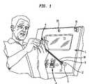
- FIG. 1is an environmental view depicting a man examining a battery operated, hand-held electronic device attached to the security apparatus of present invention
- FIG. 2is an isometric view of the device engaging means of the present invention
- FIG. 2Ais an isometric view showing the tie-box assembly of the present invention.
- FIG. 2Bis a cross-sectional view along line 2 B- 2 B of FIG. 2 showing the daughterboard within the daughterboard support plugged into the tie-box card edge connector;
- FIG. 2Cis a view of the interior and the exterior of the top part of a daughterboard housing containing a daughterboard;
- FIG. 2Dis an exploded view of the top and bottom of the daughterboard housing, the tie-box, tie-box cover and tie-box pad;
- FIG. 2Eis an exploded perspective view of the upper and lower sections of the clamping means used in conjunction with the tie-box assembly;
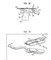
- FIG. 3is partial cut-a-way view of the support of the security display apparatus of the present invention, showing the disposition of the electronic recoiler device;
- FIG. 4is an isometric view of the recoiler exploded from its housing, showing electrical connections to the base of the device engaging means, as well as the electrical cords connecting the device to the alarm system and power source;
- FIG. 5is an exploded isometric view of the recoiler showing the spring-actuated retractor mechanism, daughter printed circuit board, electrical plugs connecting to the daughterboard, electrical connections to the retractor spring and tether mechanism, and electrical leads to a power source and an alarm system;
- FIG. 6is a side cross sectional view of the display apparatus depicting the actuation of alarm systems and security camera when the tethering means that connects to a hand-held device engaging means is severed or disconnected;
- FIG. 7is a block flow diagram depicting the functions of the motherboard which control the display device.
- FIG. 8is a block wiring diagram of the security display apparatus of the present invention.
- the present inventionis a security device for the display of battery operated, hand-held electronic devices, generally designated A.
- Such devicesinclude cell phones, calculators, digital cameras, hand-held computers, portable music playback and/or recording devices or the like.
- the inventionincludes a three-part device engaging means, generally designated B, provided for each device A to be displayed. Devices A (three are shown) are separately mounted on a device support, generally designated C. Device support C supports and houses the apparatus components of the instant invention.
- a tether 10is provided for each displayed device A.
- Each device engaging means Bis adapted to connect the displayed device A carried thereby to one end of the tether 10 associated with that displayed device.
- Each tether 10consists of two electrically conductive metal cables, preferably steel cables, most preferably stainless steel cables.
- each tether 10may comprise a single, coaxial, shielded cable to provide a single sheathed one wire appearance.
- tethers with two visible metal cablesare described and illustrated. It is to be understood that a tether with a coaxial cable will function in the same manner as a tether with the two separate conductive cables.
- Each tether 10extends through a separate opening in the surface of support C. Directly behind each opening is a female positioning component 23 with a uniquely shaped recess 12 , best seen in FIGS. 3 and 4 .
- the end of the tether that is not connected to the displayed device Ais connected to an electronic recoiler device, generally designated D, located within support C, through opening 12 in component 23 .
- FIG. 3shows the general arrangement and mounting of the electronic recoiler D behind the surface of support C.
- Numerals 2 , 3 , 4 , 5 , 6 and 7denote components of support C that hold the mechanism of recoiler D and its housing 13 on the support. Housing 13 encloses the mechanism of the recoiler.
- Cable 17is an optional lead to an external alarm system that extends from motherboard 20 , situated within recoiler housing 13 .
- Cable 18is a lead that extends from motherboard 20 to an external DC power supply means 30 , which provides power to power management circuitry located on the motherboard.
- Tether 10extends from recoiler D, passes through the surface of support C and through opening 12 in female positioning component 23 and enters tie-box 22 , which forms part of the device engaging means B, through male positioning component 24 (shown in FIG. 4 ) where it connects to card edge connector 15 c (see FIG. 2B ).
- Component 24has a shape that corresponds to the shape of opening 12 such that the tethered device A can only mount on support C in a single orientation.
- FIG. 4illustrates the internal components of recoiler D.
- Each recoiler Dincludes a spring-loaded recoiler mechanism 14 and a printed circuit motherboard 20 .
- the motherboardcarries power management circuitry, power level sensing circuitry, alarm circuitry and audible alert or siren means, all of which are known in the art.
- Lead 17feeds the output from motherboard 20 to an optional external alarm system.
- Lead 18with connector 29 at the end thereof, preferably a keyed input connector to avoid tampering, extends from motherboard 20 to the external DC power supply.
- pin connector 37Connecting to motherboard 20 are pin connector 37 which brings power to the motherboard 20 and sends alarm signals out (see FIG. 5 ), and a pin connector 39 which transmits power from motherboard 20 to recoiler springs 21 and 21 a (seen in FIG. 5 ) via wire connectors 41 and 41 a .
- the tie-box 22Also visible in FIG. 5 is the tie-box 22 , having a tie-box cover 22 c (seen in FIG. 4 ) which in turn is covered by a tie-box pad 22 p to which the device engaging means B is attached.
- Alarm and power cable 26emanates from daughterboard 15 (see FIG. 2B ) situated within tie-box 22 . It carries a connector 28 which connects to the display device A. Tether 10 extends from opening 12 in female positioning component 23 into tie-box 22 via male positioning component 24 . Also depicted in FIG. 4 is the off-hook optical sensor 8 located on component 23 .
- the display system of the present inventionpermits a potential customer to approach a display having several devices A mounted thereon, select the device of interest and examine that device.
- the selected device, and the device engaging means B within which it is secured,can then be pulled away from the display support toward the customer, against the spring action of the spring-loaded recoiler mechanism 14 ( FIG. 4 ).
- the recoilerexerts a retracting force on the tether to which the displayed device is attached.
- the customercan hold and handle the selected device to get the feel of the device in his or her hand and examine the device closely to determine if he or she wishes to purchase the product.
- the recoilerwill return the device back to it position on the display support, in the proper orientation.
- the deviceWhile the customer is examining the device, the device cannot be removed from the device engaging means B. Further, it cannot be moved to a position too far away from the display because of tether 10 . Thus, the customer can examine the device conveniently but cannot remove the device from the display apparatus without severing tether 10 , or forcibly removing it from device engaging means B.
- Those measureswill include at least one or all of the following: an audible alarm 16 from the display itself, an external audible alarm from the alarm system of the display area, a radio frequency (RF) alarm signal transmitted to remotely located security personnel, a visual image of the perpetrator taken by a camera 19 mounted in the display apparatus ( FIG. 1 ) transmitted by wire or RF signal to a security office where it is made visible on video display means 80 therein, and/or an alarm message displayed on video display means 11 .
- RFradio frequency
- An additional safeguard against pilferage of devices Ais placing an RFID or electronic article surveillance (EAS) tag within the displayed device and having sensors connected to an alarm system at the exits of the display area or store or both.
- RFID or EAS tagsare commercially available.
- a perpetratorwill set off an alarm when passing through any of the aforesaid exits.
- Motherboard 20is typically situated within recoiler housing 13 and attached to the recoiler mechanism. However, motherboard 20 may instead be situated outside recoiler housing 13 or in a separate housing.
- Each recoiler of the display apparatushas an associated motherboard 20 that is supplied with DC power from an external power supply 30 , as indicated in block wiring diagram, FIG. 8 .
- the power supplydelivers about 12 VDC to motherboard but voltages that fall within the range of about 6 VDC to about 12 VDC can be used.
- the external power supplyis connected to the motherboard via a connecting plug 29 , which is preferably a keyed and locking input connector.
- Electronic circuitry on motherboardsteps the DC voltage supplied by the external power supply down to lower pulsating DC voltages to power the displayed device connected thereto.
- an input voltage of about 12 VDCis converted to about 6 VDC at 1.4 A.
- a range of voltagesmay be provided according to the requirements of the specific device to be displayed.
- each motherboardcontains circuitry, as known in the art, that detects the polarity reversal and shuts recoiler down, thereby protecting it and displayed device A from damage. Such an event might occur if the poles of input connector 29 were reversed as a result of tampering.
- Each motherboardcan be connected to an external alarm system via lead 17 and connector 33 .
- the power signal from external power supply 30enters the motherboard via a connector 37 , typically a pin connector.
- Connector 37also provides connection for the alarm signal output to an external alarm via lead 17 and connector 33 .
- Current fed to recoiler springs 21 and 21 aexits the motherboard via connector 39 , which is also typically a pin connector.
- Wires or other electrically conductive elements 41 , 41 aconnect the power output of the motherboard to recoiler springs 21 and 21 a.
- Each motherboardalso contains circuitry that delivers a light path to off-hook sensor 8 , located on female positioning component 23 , via a fiber-optic tube or a multiplicity of fiber-optic tubes.
- Each motherboardalso has an impedance variance detection circuit that provides an alarm signal to an audible PNP transistor device. The alarm signal can activate an external alarm system, such as a display alarm, when that circuitry senses an alarm condition.
- Each motherboardalso carries an integrated alarm module and siren.
- the alarm modulecan be activated when circuitry on the motherboard senses an alarm condition, when interfacing with an existing external alarm system is not an option due to the absence of such an external alarm system, when cable management to interface with an existing external alarm system is difficult or when simple discrete alarming is required.
- Each motherboardadditionally has circuitry that controls wireless transmission of an alarm signal to a remote location via wireless transmission means.
- the wireless signalmay be used to alert security personnel via visual or audible means as to the location and specific item that is being pilfered.
- Another circuit module on the motherboardis a video capture circuit that stores pixilated images from digital camera 19 mounted on the security display.
- Each motherboardincludes counting circuitry 74 that is advanced each time the associated device is removed from the display.
- the counting circuitry 74can count the occurrence of an event such as the lifting of any device A from the display support, record and store downloadable data in a processor relating to that event, such as the total occurrences of such events, and transmit that data via a USB port or other port means for display on means such as a video monitor or to activate an electromechanical readout counter, for analysis at a remote location.
- Each motherboardalso carries circuitry to deliver output power to daughterboard 15 located in tie-box 22 via electrically conductive recoiler mechanism springs 21 and 21 a , and the electrically conductive two stranded tether 10 (or alternatively via two electrically separate wires within a single strand of coaxial cable).
- the combination of motherboard 20 and daughterboard 15which comprises power management circuitry, deliver power to the displayed device at a level suitable to the requirements of that device.
- Each motherboardhas circuitry to control activation of peripheral devices such as LCD monitors and media players when signals are received from remote sensors.
- each motherboardhas optical sensing circuitry that receives signals from off-hook optical sensor 8 , when a device A is lifted from device support C. That circuitry then transmits signals that actuate components such as media players and processors that provide digitized video and audio signals to video means display 11 and to audio speaker means 16 , wherein product information is visibly displayed and made audible.
- Circuitry on the motherboardenables a user to select which information is displayed on video display 11 , while locking out the display of unselected information.
- a display activation button (or jog button) 9is provided adjacent each device on support C. That button typically comprises a metallic disc that is electrically insulated from the support, when the support is an electrical conductor.
- the metallic discis electrically connected to the input of a PNP transistor on the motherboard associated with the adjacent device, which acts as a switch when a person touches the disc, completing the circuit through ground.
- the output from the transistoractivates a track selector on media player 61 or an equivalent connection on a processor, to display video on video display means 11 and produce audible sound on audio speaker means 16 .
- video display functions and audio amplification and sound productionare combined by use of a monitor.
- the media player 61is a flash card media player wherein the information to be displayed and heard is contained on a flash media card. Track activation and selection is produced by a person touching display activation button (or jog button) 9 as described above.
- Additional circuitry and signal reception means on the motherboardenable the information displayed on video display means 11 and heard on audio speaker means 16 to be driven by wired or wireless broadband transmission or satellite transmission.
- the video and audio information to be conveyed by the displaymay be received by the media player from broadband or satellite transmission means.
- Media player 61 controlled by display activation button (or jog button) 9determine the display, as described above.
- display activation button (or jog button) 9determine the display, as described above.
- the information conveyed by the display apparatusmay be remotely transmitted and modified and conveniently updated.
- the functions of motherboard 20are illustrated in FIG. 7 .
- Each daughterboard 15situated in a tie-box 22 , is a printed circuit (PC) board containing circuitry that provides the logic for device power management.
- the circuitrysupplies the correct voltage and regulates the current delivered to the device A attached thereto.
- the device power management circuitry on the daughterboardcan step down from the voltage delivered to it from the motherboard to accommodate the power needs of the particular device A being displayed.
- the daughterboardalso contains circuitry that provides the logic for the security of device A.
- the circuitryincludes sensing circuitry that monitors the power level from the daughterboard to device A to detect variances or disruptions, such as loss of power, a dead short, a short to ground, an open circuit, and the like. In the event the “electronic fingerprint” of device A in its normal display condition is altered, the daughterboard delivers an “alarm condition” signal to the associated motherboard.
- the daughterboarddelivers power to device A via power delivery cable 26 directly connected between the daughterboard ( FIGS. 2 , 4 ) and a device specific power plug 28 , which fits into the power port of device A. Since current is always delivered to the battery of device A, whether or not device A is in use, the device battery 82 is always kept at its maximum charge state. Therefore, the customer will always examine a fully charged product.
- the daughterboardwith its attached power delivery cable may be produced as a disposable or exchangeable unit that plugs directly into a card edge connector situated in the tie-box, or is placed in housing 15 h which fits into tie-box 22 and then plugs into card edge connector 15 c , as in the version depicted in FIG. 2B .
- the daughterboardcan be easily and conveniently exchanged for another daughterboard having power management circuitry that meets the power requirements of the new device A, when a new device A is mounted on the display.
- FIG. 8is a block diagram illustrating the power and alarm circuitry arrangement of the security display apparatus of the present invention. It can be seen that an AC power source supplies power to the main power supply 30 and (optionally) to an external central alarm control circuit 32 .
- the main power supply 30simultaneously feeds DC power (designated 31 ) to each electronic recoiler device D.
- Each recoileris associated with a motherboard 20 which under the appropriate conditions transmits an alarm signal (designated 35 ) and a power signal (designated 36 ) through the female positioning device 23 to the daughterboard contained in the tie-box 22 which forms part of the associated device engaging means B.
- the daughterboard 15transmits the alarm signal 35 and the power signal 36 , having the appropriate power level for device A, to device A via hard connections.
- the motherboard 20also transmits alarm signal 35 to optional external central alarm control 32 , as well as an alarm module contained on the motherboard 20 .
- a battery backup 34supplies DC power to the electronic recoiler devices D and the external central alarm control 32 in case of power failure.
- off-hook sensor means 8detects same and transmits a signal via motherboard 20 ( FIG. 4 ) which activates video display means 11 .
- Sensor 8is preferably an optical detector, such as an infrared detector, a photo cell detector, a proximity detector or a fiber optic sensor, all of which are known in the art. Most preferably, sensor 8 is a fiber optic sensor.
- Video display means 11can be any a conventional cathode ray tube (CRT) display screen, plasma display screen or LCD display screen. Preferably an LCD display screen is utilized.
- CTRcathode ray tube
- the video displayshows the potential customer video, printed or graphic information promoting the features of the specific device A that the potential customer lifted from the display support. Sound associated with the video display is provided to the potential customer via at least one audio speaker 16 , which is driven by a differential amplifier attached to motherboard 20 ( FIG. 4 ) or the monitor's internal circuitry.
- the potential customertouches display activation means button 9 (also known as a “jog” button) situated on support C adjacent to the selected device. That causes a signal to be transmitted via motherboard 20 ( FIG. 4 ) that first selects the appropriate menu item by jogging down the on screen list, then activates display of a specification comparison chart on video display means 11 via media player or media processor means.
- the display activation meansmay be selected from a membrane switch, capacitance switch or touch screen.
- the display device of the present inventionprovides means to continuously recharge the battery of each of the displayed hand-held electronic devices A while simultaneously providing alarm means to prevent or signal pilferage of displayed devices. This is accomplished by providing a continuous trickle charge circuit on each motherboard.
- the trickle charge from the motherboard 20is sent through recoiler mechanism springs 21 and 21 a ( FIGS. 4 , 5 ) and tether 10 ( FIGS. 1-6 ) to device A.
- recoiler mechanism springs 21 and 21 aFIGS. 4 , 5
- tether 10FIGS. 1-6
- Tether 10exits device support C via female positioning component 23 and enters male positioning component 24 (see U.S. Pat. No. 6,659,382) which forms part of tie-box 22 ( FIG. 2 ).
- the tie-boxis a component of device engaging means B.
- the two electrically conducting cables which comprise tether 10terminate in tie-box 22 where they electrically connect to daughterboard 15 via card edge connector 15 c ( FIG. 2B ) contained therein. Each cable acts as a single electrically conducting wire.
- the same two wires of the tetherpreferably carry both current to charge the associated displayed device A and alarm signals to motherboard 20 , should the connection to device A be disrupted.
- device engaging means Bincludes three main components: (i) a clamping means comprising a hollow top section 38 , and a hollow bottom section 40 which receive and retain the device A to be displayed, (ii) a hollow tie-box 22 containing card edge connector 15 c ( FIG. 2B ) to connect with daughterboard 15 , contained in daughterboard housing 15 h , which comprises daughterboard housing top 15 t and daughterboard housing bottom 15 b ( FIG. 2-FIG . 2 D), and (iii) positioning component 24 attached to tie-box 22 .
- daughterboard housing 15 hprovides convenience in handling daughter board 15 which is electrically connected to cable 26 , in some embodiments of the invention that housing can be omitted, with daughterboard 15 situated directly in tie-box 22 .
- Tie-box 22also comprises tie-box cover 22 c with optional flexible plastic tab 67 which protrudes through opening 68 in tie-box pad 22 p ( FIGS. 2 , 2 B, 2 D).
- Optional flexible plastic tab 67has a metallic strip on its underside (not shown) which is depressed when device A is placed in device engaging means B, and locked onto tie-box 22 . That closes an optional alarm circuit by making contact with optional electrical contacts (not shown) extending from daughterboard 15 , through the top of daughterboard housing 15 t ( FIG. 2D ).
- the foregoing arrangementadds a further degree of protection to device A by tripping an alarm should an attempt be made to remove daughterboard housing 15 h , device engaging means B, or tie-box pad 22 p.
- Another security featuremay be provided by optional flexible plastic transverse spine 15 s on daughterboard housing top 15 t which snaps into optional opening 69 in tie-box pad 22 p thereby locking daughterboard housing 15 h in place within tie-box 22 ( FIGS. 2A , 2 C, 2 D).
- a flat edged toolmay be used to depress spine 15 s when removing housing 15 h from tie-box 22 .
- tie-box cove 22 cmay be readily manufactured without flexible tab 67 , openings 68 and 69 on tie-box pad 22 p may be omitted and spine 15 s on housing top 15 t may be omitted as required.
- tie-box cover 22 csnaps down into tie-box 22 and is held on place by male snap fittings 70 a,b,c,d and female snap fittings 71 a,b,c,d .
- tie-box cover 22 cWith tie-box cover 22 c in place on tie-box 22 , daughterboard housing 15 h containing daughterboard 15 can be inserted into tie-box 22 via tie-box entrance 22 e ( FIGS. 2A , 2 D)
- Tie-box 22also comprises tie-box pad 22 p , which fits on top of tie-box cover 22 c and also fits between top part 38 and bottom part 40 of the clamping means.
- Tie-box pad 22 pis firmly connected to tie-box 22 by any convenient connecting means known in the art, preferably reversible connection means, to facilitate assembly and disassembly.
- That connecting meansmay comprises a “slide on” means 62 illustrated in FIG. 2A (two seen, two at back not seen) wherein rails 62 r integral to tie-box 22 are engaged by couplings 62 c integral to tie-box pad 22 p.
- Tie-box 22 and daughterboard housing 15 hare preferably formed from plastic materials due to their relatively low cost, most preferably ABS, due to its durability and ease of handling, and may be conveniently formed by a variety of processes known in the art such as injection molding, machining or thermoforming where applicable.
- Sections 38 and 40 of the clamping meansmay be formed from any commonly used metal or alternatively from plastic or polymeric materials by conventional processes providing that the clamping means so produced, when used as a component of device engaging means B, has sufficient strength to securely retain device A.
- top section 38 and bottom section 40 of the clamping meansmay be adjusted to tightly fit and securely retain device A or may be custom made to tightly fit around and securely retain device A when used in conjunction with tie-box 22 .
- brackets 63are arranged on top section 38 and bottom section 40 to receive a small electronic device A, such as a cell phone.
- sections 38 and 40 of the clamping deviceare placed on top of tie-box pad 22 p so that top plate 65 and bottom plate 66 are in contact with tie-box pad 22 p and are aligned so that threaded hole 54 in tab 48 and threaded hole 56 in tab 46 line up with through security hole 50 in tie-box 22 ( FIGS. 2 and 2A ) so that security screw 58 ( FIG. 2E ) can be inserted and tightened thereby attaching top section 38 and bottom section 40 to tie-box 22 and clamping device A to tie-box 22 .
- through security hole 50may also be extended to pass through the walls of daughterboard housing 15 h , generally by providing holes 15 g ( FIG. 2D ) in the walls of bottom section 15 b that line up with through hole 50 of tie-box 22 when daughterboard 15 is engaged by card edge connector 15 c.
- FIG. 2EAnother version of the clamping means to be used in conjunction with tie-box 22 is illustrated in FIG. 2E wherein the same numbers are used to describe parts analogous to those in FIG. 2 .
- upper section 38 of the clamping meansis provided with opening 42 designed to accommodate an antenna on device A
- lower section 40is provided with opening 44 which provides access for device power plug 28 ( FIG. 2 ) to a power input port for the particular device to be displayed.
- top section 38 and bottom section 40each have a securely attached tab 46 and 48 located along the central longitudinal axis of their underside and protruding at right angles therefrom.
- Tab 46has centrally located threaded opening 54 (not seen), and tab 48 has centrally located threaded opening 56 , with said openings disposed so that opening 54 of tab 46 aligns with through opening 50 of tie-box 22 ( FIG. 2 ) and opening 56 of tab 48 aligns with the other end (not seen) of through opening 50 of tie-box 22 ( FIG. 2 ) so that a screw 58 ( FIG.
- 2Emay be inserted into opening 54 of tab 46 and screwed in so that it passes through the through opening 50 of tie-box 22 from which it emerges and screws into opening 56 of tab 48 and locks a device A, contained within the hollow of top section 38 and the hollow of bottom section 40 within device engaging means B formed by top section 38 , tie-box 22 with tie-box pad 22 p and bottom section 40 .
- Device Ais securely retained in between the sections and cannot be removed from device engaging means B when sections 38 and 40 are secured to the tie-box.
- Tie-box 22which also contains male positioning component 24 , may be formed from any commercially available workable material such as metals and polymers but is preferably formed from polymeric materials, most preferably ABS plastics due to ease of processing, durability and economy, by molding from commercially available plastic or polymeric formulations or by other methods known in the art or by machining.
- male positioning component 24projects from the underside of tie-box 22 .
- Male positioning component 24has a particular cross sectional shape (ovoid as illustrated) that corresponds to the shape of opening 12 of female positioning component 23 on device support C.
- Male positioning component 24can be received by female positioning component 23 in only one orientation, thereby setting the orientation of device A relative to the support.
- This featurecan be further refined, as explained in the herein incorporated U.S. Pat. No. 6,659,382, through the use of additional correspondingly shaped interlocking features, such as ribs and a rib-receiving channel, permitting the device to be received on the support in only a single orientation.
- Tether 10emerges from male positioning component 24 and extends through opening 12 in female positioning component 23 to the rear of device support C.
- FIG. 5which is an exploded view of electronic recoiler device D
- the two strands of tether 10 that emerge from the backside support Care kept from making electrical contact with each other in order to avoid a short circuit resulting in a false alarm.
- Each of the two strands of tether 10is wound onto a separate spool 45 a and 45 b .
- Spools 45 a and 45 bare electrically insulated from each other.
- Each spoolhas a separator 45 as and 45 bs that separates the spool into two sections 45 a 1 , 45 a 2 and 45 b 1 , 45 b 2 respectively.
- Spool section 45 a 2 of spool 45 areceives one strand of two stranded tether 10 .
- Spool section 45 b 2receives the second strand of two stranded tether 10 .
- Coiled spring 21is wound around section 45 a 1 of spool 45 a .
- Coiled spring 21 ais wound around spool section 45 b 2 of spool 45 b .
- the ends 21 e and 21 ae of coil springs 21 and 21 aare attached to the respective cores 45 ac and 45 bc of spools 45 a and 45 b on which they are wound.
- Coil spring 21 wound on section 45 a 1 of spool 45 ais electrically connected to the strand of tether 10 wound on section 45 a 2 of spool 45 a .
- Coil spring 21 a wound on section 45 b 1 of spool 45 bis electrically connected to the second strand of tether 10 wound on section 45 b 2 of spool 45 .
- Coil spring 21 , and the strand of tether 10 to which it is electrically connected,are electrically insulated from coil spring 21 a , which is electrically connected to the second strand of tether 10 .
- both spools 45 a and 45 bhave a central opening 47 to receive an axle 49 around which spools 45 a and 45 b rotate.
- a similar arrangement to that described abovemay be achieved with two pairs of single sectioned spools, wherein each pair of spools is attached in a side-by-side arrangement and the two pairs of single sectioned spools are combined to form an arrangement similar to that depicted in FIG. 5 .
- the spring loaded recoiler mechanism 14may be used in conjunction with a tether 10 that is a single coaxial cable containing two electrically conductive strands.
- a tether 10that is a single coaxial cable containing two electrically conductive strands.
- three spoolsmay be employed, wherein the coaxial cable is received by a central spool flanked by two spools on which coil springs are wound in the manner described above.
- One of the two electrically conductive strandsis electrically connected to one of the coil springs and the second of the two electrically conductive strands is connected to the second of the two coil springs.
- the customerwhen he or she removes the displayed device A from device support means C, as indicated in FIG. 1 causes spools 45 a and 45 b to rotate in a manner which tightens coil springs 21 and 21 a on spools 45 a and 45 b thereby generating a retracting force which opposes the lifting of device A from device support C and causes device A to be returned to device support C when released by the customer.
- the present inventionis an improvement of the security device for the display of hand-held items of the type disclosed in U.S. Pat. No. 6,659,382.
- the electronic recoiler device of the security display apparatus of the present inventioncombines the function of tethering the displayed devices while at the same time supplying power required by the displayed devices by means of a continuous electrical connection from a power supply to the displayed device while providing wire and wireless alarm functions, as well as visual perpetrator identification and specific product information, and providing product comparisons to the potential customer by visual and audible means.
Landscapes
- Physics & Mathematics (AREA)
- General Physics & Mathematics (AREA)
- Engineering & Computer Science (AREA)
- Computer Vision & Pattern Recognition (AREA)
- Burglar Alarm Systems (AREA)
Abstract
Description
Claims (51)
Priority Applications (1)
| Application Number | Priority Date | Filing Date | Title |
|---|---|---|---|
| US11/708,243US7667601B2 (en) | 2006-02-23 | 2007-02-20 | Apparatus for secure display, interactive delivery of product information and charging of battery-operated hand held electronic devices |
Applications Claiming Priority (2)
| Application Number | Priority Date | Filing Date | Title |
|---|---|---|---|
| US77593506P | 2006-02-23 | 2006-02-23 | |
| US11/708,243US7667601B2 (en) | 2006-02-23 | 2007-02-20 | Apparatus for secure display, interactive delivery of product information and charging of battery-operated hand held electronic devices |
Publications (2)
| Publication Number | Publication Date |
|---|---|
| US20070194918A1 US20070194918A1 (en) | 2007-08-23 |
| US7667601B2true US7667601B2 (en) | 2010-02-23 |
Family
ID=38427603
Family Applications (1)
| Application Number | Title | Priority Date | Filing Date |
|---|---|---|---|
| US11/708,243Expired - Fee RelatedUS7667601B2 (en) | 2006-02-23 | 2007-02-20 | Apparatus for secure display, interactive delivery of product information and charging of battery-operated hand held electronic devices |
Country Status (1)
| Country | Link |
|---|---|
| US (1) | US7667601B2 (en) |
Cited By (48)
| Publication number | Priority date | Publication date | Assignee | Title |
|---|---|---|---|---|
| US20100175438A1 (en)* | 2009-01-13 | 2010-07-15 | Invue Security Products Inc. | Combination non-programmable and programmable key for security device |
| US20110042331A1 (en)* | 2009-08-21 | 2011-02-24 | Target Brands, Inc. | Method and Apparatus for Securely Displaying Media Products |
| US20110084689A1 (en)* | 2009-10-13 | 2011-04-14 | Sennco Solutions, Inc. | Circuit, system and/or method for detecting an electrical connection between an electrical device and a power supply |
| US20110309934A1 (en)* | 2010-06-21 | 2011-12-22 | Merchandising Technologies, Inc. | Display For Hand-Held Electronics |
| US20110309928A1 (en)* | 2010-06-21 | 2011-12-22 | Mti, Inc | Display For Hand-Held Electronics |
| US20120226586A1 (en)* | 2011-03-04 | 2012-09-06 | Tigerdirect, Inc. | Computer systems and methods for interactive shopping experience in retail stores |
| US20130135803A1 (en)* | 2009-09-17 | 2013-05-30 | Target Brands, Inc. | Display apparatus and method |
| WO2014056061A1 (en)* | 2012-10-08 | 2014-04-17 | Jacques Matias | Tether lock for central control unit of a display stand for articles on sale |
| US8710988B1 (en)* | 2011-08-11 | 2014-04-29 | William Lee Foster | Method for detecting motion of an electrical device or apparatus |
| US20140118893A1 (en)* | 2012-10-26 | 2014-05-01 | Marcon International, Inc. | Asset retention device for an asset retention system |
| US20140159898A1 (en)* | 2010-06-21 | 2014-06-12 | Mobile Technologies, Inc. | Display for hand-held electronics |
| US8810437B2 (en)* | 2011-02-02 | 2014-08-19 | Mapquest, Inc. | Systems and methods for generating electronic map displays with points-of-interest information based on reference locations |
| US8878673B2 (en) | 2011-05-19 | 2014-11-04 | Invue Security Products Inc. | Systems and methods for protecting retail display merchandise from theft |
| US20150091729A1 (en)* | 2013-09-29 | 2015-04-02 | Invue Security Products Inc. | Systems and methods for protecting retail display merchandise from theft |
| US9041537B2 (en) | 2012-04-03 | 2015-05-26 | Invue Security Products Inc. | Pre-alarm for abnormal merchandise handling |
| DE102014101501A1 (en)* | 2014-02-06 | 2015-08-06 | Oliver Zander | Line security system for securing goods for goods such as mobile phones, cameras, tablets or the like. |
| US9125501B2 (en)* | 2012-07-25 | 2015-09-08 | Sennco Solutions, Inc. | Fixed display pedestal, system and/or method for securing an article |
| US9152986B2 (en) | 2011-12-07 | 2015-10-06 | Adflow Networks Inc. | Apparatus, method and process of influencing information gathered by a tethered item and computer-readable medium thereof |
| US9443404B2 (en) | 2014-02-14 | 2016-09-13 | Invue Security Products Inc. | Tethered security system with wireless communication |
| TWI556535B (en)* | 2014-04-29 | 2016-11-01 | 移動技術公司 | Display for hand-held electronics |
| US20160335860A1 (en)* | 2014-01-23 | 2016-11-17 | InVue Security Product Inc. | Systems and methods for security sensing in a power cable for an article of merchandise |
| USD773465S1 (en) | 2013-08-22 | 2016-12-06 | Palmer Distributors, Incorporated | Docking station for an electronic device |
| US9805564B1 (en) | 2015-10-12 | 2017-10-31 | Invue Security Products Inc. | Recoiler for a merchandise security system |
| US9818274B2 (en) | 2015-05-28 | 2017-11-14 | Invue Security Products Inc. | Merchandise security system with optical communication |
| US9830787B2 (en) | 2012-08-30 | 2017-11-28 | Invue Security Products Inc. | Merchandise security system including retractable alarming power cord |
| US9892604B2 (en) | 2016-04-15 | 2018-02-13 | Mobile Tech, Inc. | Gateway-based anti-theft security system and method |
| US9911334B2 (en)* | 2016-07-12 | 2018-03-06 | Siemens Industry, Inc. | Connected vehicle traffic safety system and a method of warning drivers of a wrong-way travel |
| US10047904B1 (en) | 2012-08-30 | 2018-08-14 | Sennco Solutions, Inc. | Apparatus, system and method for securing, attaching and/or detaching a device to a fixture |
| US10101770B2 (en) | 2016-07-29 | 2018-10-16 | Mobile Tech, Inc. | Docking system for portable computing device in an enclosure |
| US10198035B2 (en) | 2012-12-05 | 2019-02-05 | Mobile Tech, Inc. | Docking station for tablet device |
| US10223881B2 (en) | 2015-02-18 | 2019-03-05 | Invue Security Products Inc. | System and method for calibrating a wireless security range |
| US10251144B2 (en) | 2015-12-03 | 2019-04-02 | Mobile Tech, Inc. | Location tracking of products and product display assemblies in a wirelessly connected environment |
| US10269202B2 (en) | 2001-12-27 | 2019-04-23 | Mobile Tech, Inc. | Intelligent key system |
| US10373456B2 (en) | 2009-01-10 | 2019-08-06 | Mobile Tech, Inc. | Display for hand-held electronics |
| USD855358S1 (en) | 2017-10-12 | 2019-08-06 | Target Brands, Inc. | Display table |
| US10482739B2 (en) | 2015-06-25 | 2019-11-19 | Invue Security Products Inc. | Wireless merchandise security system |
| US10490040B1 (en) | 2018-11-07 | 2019-11-26 | Vanguard Products Group, Inc. | Anti-theft device utilizing an optical echo chamber for monitoring integrity of a tether cable connection |
| US10517056B2 (en) | 2015-12-03 | 2019-12-24 | Mobile Tech, Inc. | Electronically connected environment |
| US10593443B1 (en) | 2019-01-24 | 2020-03-17 | Mobile Tech, Inc. | Motion sensing cable for intelligent charging of devices |
| US10728868B2 (en) | 2015-12-03 | 2020-07-28 | Mobile Tech, Inc. | Remote monitoring and control over wireless nodes in a wirelessly connected environment |
| US10748363B2 (en) | 2017-03-21 | 2020-08-18 | Marcon International Inc | Key fob for a key management system |
| US11109335B2 (en) | 2015-12-03 | 2021-08-31 | Mobile Tech, Inc. | Wirelessly connected hybrid environment of different types of wireless nodes |
| US20210355713A1 (en)* | 2020-05-14 | 2021-11-18 | Invue Security Products Inc. | System for securing items of merchandise from theft |
| US11270561B1 (en) | 2018-11-07 | 2022-03-08 | Vanguard Products Group, Inc. | Anti-theft device utilizing an optical communication channel to control power output of an inductive charging coil |
| US11344140B2 (en) | 2009-01-10 | 2022-05-31 | Mobile Tech, Inc. | Display for hand-held electronics |
| US11540350B2 (en) | 2018-10-25 | 2022-12-27 | Mobile Tech, Inc. | Proxy nodes for expanding the functionality of nodes in a wirelessly connected environment |
| US20220408943A1 (en)* | 2021-06-28 | 2022-12-29 | Apple Inc. | Display Stand Unit |
| US11804115B1 (en)* | 2021-09-30 | 2023-10-31 | Vanguard Products Group, Inc. | Universal security stand for wearable electronics with wireless charging capability |
Families Citing this family (41)
| Publication number | Priority date | Publication date | Assignee | Title |
|---|---|---|---|---|
| US20110254661A1 (en) | 2005-12-23 | 2011-10-20 | Invue Security Products Inc. | Programmable security system and method for protecting merchandise |
| US7737846B2 (en)* | 2005-12-23 | 2010-06-15 | Invue Security Products Inc. | Security system and method for protecting merchandise |
| US7737843B2 (en)* | 2005-12-23 | 2010-06-15 | Invue Security Products Inc. | Programmable alarm module and system for protecting merchandise |
| US8081075B2 (en) | 2006-03-31 | 2011-12-20 | Checkpoint Systems, Inc. | Tether cord and sensor alarms |
| US7701339B2 (en)* | 2006-03-31 | 2010-04-20 | Checkpoint Systems, Inc. | System and method for securing and displaying items for merchandising |
| US8102262B2 (en) | 2006-03-31 | 2012-01-24 | Checkpoint Systems, Inc. | Charging merchandise items |
| US20080156922A1 (en)* | 2007-01-03 | 2008-07-03 | Vira Manufacturing, Inc. | Apparatus for secure display of small electronic devices having an essential signal or power cord |
| US8122744B2 (en)* | 2007-03-28 | 2012-02-28 | Checkpoint Systems, Inc. | Cable wrap security device |
| US7724135B2 (en)* | 2007-03-29 | 2010-05-25 | Checkpoint Systems, Inc. | Coiled cable display device |
| US20090079566A1 (en)* | 2007-09-24 | 2009-03-26 | Invue Security Products, Inc. | Security device including sensor having an extension |
| EP2210244A1 (en)* | 2007-09-28 | 2010-07-28 | Checkpoint Systems, Inc. | Coiled cable display device |
| US20090223908A1 (en)* | 2008-03-07 | 2009-09-10 | Wal-Mart Stores, Inc. | Device Display Unit |
| US8581985B2 (en)* | 2008-11-10 | 2013-11-12 | Invue Security Products Inc. | Merchandise security system including display stand having video camera |
| US20100176945A1 (en)* | 2009-01-14 | 2010-07-15 | Invue Security Products Inc. | Detachable carriage for merchandise security system |
| CA2664237C (en) | 2009-04-27 | 2016-12-06 | Joel Ferguson | Modular hand-held electronic device charging and monitoring system |
| FR2954558B1 (en)* | 2009-12-18 | 2012-03-23 | Saaa Sas Systemes D Automatismes D Alarmes Automatiques | SILENCED ANTI-THEFT PROTECTION SYSTEM FOR GOODS PRESENTED TO THE PUBLIC |
| EP2339554A1 (en)* | 2009-12-23 | 2011-06-29 | Tag Company (UK) Limited | A system apparatus and method for electronic article surveillance |
| US20120099256A1 (en)* | 2010-10-21 | 2012-04-26 | Invue Security Products Inc. | Sensor including retractable power adapter cord |
| US8847759B2 (en) | 2010-11-16 | 2014-09-30 | Invue Security Products Inc. | Merchandise display security device including means for retaining power adapter cord |
| GB201019736D0 (en)* | 2010-11-22 | 2011-01-05 | Sector Design & Marketing Ltd | Electronic device display unit |
| US20120188082A1 (en)* | 2011-01-26 | 2012-07-26 | Invue Security Products Inc. | Merchandise display security device including removable and movable cable collection tube |
| US8674833B2 (en) | 2011-01-31 | 2014-03-18 | Invue Security Products Inc. | Universal camera sensor having movable mount for retaining power connector |
| EP2673756A4 (en)* | 2011-02-08 | 2014-06-25 | Dci Marketing Inc | Powered security display device |
| US11017656B2 (en) | 2011-06-27 | 2021-05-25 | Invue Security Products Inc. | Programmable security system and method for protecting merchandise |
| US8994798B2 (en) | 2011-11-17 | 2015-03-31 | Target Brands, Inc. | 3D TV display system with sensor detecting an optical tool |
| EP2855803A4 (en) | 2012-05-21 | 2016-09-07 | Invue Security Products Inc | CABINET LOCK KEY WITH SOUND INDICATORS |
| TWM443977U (en)* | 2012-06-18 | 2012-12-21 | Mingood Entpr Ltd | Charging anti-burglar system for electronic product |
| US9402486B2 (en)* | 2012-06-28 | 2016-08-02 | Invue Security Products Inc. | Centering adapter plate for camera sensor |
| US9996173B2 (en)* | 2013-02-12 | 2018-06-12 | Illinois Tool Works, Inc. | Front panel overlay incorporating a logic circuit |
| US9940656B1 (en)* | 2013-09-25 | 2018-04-10 | Amazon Technologies, Inc. | Smart demonstration device |
| DE102013111132B3 (en)* | 2013-10-08 | 2015-03-19 | Rolf Wahlbring | Anti-theft system with power supply for an electrical device |
| CN105723426B (en) | 2013-11-15 | 2018-09-25 | Invue安全产品公司 | Tether Security Device for Electronic Keys |
| WO2015130635A1 (en)* | 2014-02-28 | 2015-09-03 | Apple Inc. | Product demonstration fixture for a portable electronic device |
| WO2016081188A1 (en) | 2014-11-18 | 2016-05-26 | Invue Security Products Inc. | Key and security device |
| CN204315011U (en)* | 2014-12-26 | 2015-05-06 | 杭州朗鸿科技有限公司 | Intelligence wearable display product safety anti-theft device |
| WO2016130762A1 (en) | 2015-02-12 | 2016-08-18 | Invue Security Products Inc. | Systems and methods for acquiring data from articles of merchandise on display |
| DE202015104068U1 (en)* | 2015-08-04 | 2016-08-08 | Oliver Zander | Presentation device with an alarm unit for goods security |
| WO2018089349A1 (en) | 2016-11-08 | 2018-05-17 | Invue Security Products Inc. | Systems and methods for acquiring data from articles of merchandise on display |
| DE102017104420A1 (en) | 2017-03-02 | 2018-09-06 | Oliver Zander | Goods security system with electrical power supply |
| US11176791B2 (en)* | 2018-06-28 | 2021-11-16 | Invue Security Products Inc. | Security systems and methods for consumer products |
| JP7380839B2 (en)* | 2020-03-12 | 2023-11-15 | 日本電気株式会社 | Recognition level estimation device, recognition level estimation method, and program |
Citations (18)
| Publication number | Priority date | Publication date | Assignee | Title |
|---|---|---|---|---|
| US5151684A (en)* | 1991-04-12 | 1992-09-29 | Johnsen Edward L | Electronic inventory label and security apparatus |
| US5246183A (en) | 1991-04-04 | 1993-09-21 | Se-Kure Controls | Security device for a hand-held remote control |
| US5552771A (en) | 1994-06-10 | 1996-09-03 | Leyden; Roger J. | Retractable sensor for an alarm system |
| US5555302A (en) | 1995-07-18 | 1996-09-10 | Wang; Chin-Yang | Mobile telephone holder |
| US5608449A (en)* | 1994-10-31 | 1997-03-04 | Rtc Industries, Inc. | Wireless interactive consumer video system |
| US5903645A (en) | 1996-10-23 | 1999-05-11 | Tsay; Wen-Feng | Clamping device for mobile phones |
| US6002921A (en) | 1997-11-17 | 1999-12-14 | Ericsson Inc. | Lockable radiotelephone cradle |
| US6386906B1 (en)* | 1998-03-16 | 2002-05-14 | Telefonix Inc | Cord management apparatus and method |
| US6476717B2 (en) | 2000-04-12 | 2002-11-05 | Cda Industries, Inc. | Tamper-proof display |
| US6659382B2 (en) | 2001-07-10 | 2003-12-09 | Vira Manufacturing, Inc. | Security device for display of hand held items |
| US6756900B2 (en) | 2002-01-04 | 2004-06-29 | Se-Kure Controls, Inc. | Voltage selectable alarm sensor |
| US20050040949A1 (en) | 2003-08-18 | 2005-02-24 | Se-Kure Controls, Ins. | Security system with mechanism for controlling cord twisting |
| US6903656B1 (en)* | 2003-05-27 | 2005-06-07 | Applied Wireless Identifications Group, Inc. | RFID reader with multiple antenna selection and automated antenna matching |
| US7015596B2 (en)* | 2003-07-03 | 2006-03-21 | Opher Pail | Electronic device display system and method |
| US7053774B2 (en) | 2003-09-12 | 2006-05-30 | Alpha Security Products, Inc. | Alarming merchandise display system |
| US20060208921A1 (en) | 2002-03-08 | 2006-09-21 | Reinhold Ott | Sensor element for a monitoring device |
| US7209038B1 (en)* | 2005-03-17 | 2007-04-24 | Protex International Corporation | Security system for power and display of consumer electronic devices |
| US7403119B2 (en)* | 2004-11-02 | 2008-07-22 | Se-Kure Controls, Inc. | Networked security system and method for monitoring portable consumer articles |
- 2007
- 2007-02-20USUS11/708,243patent/US7667601B2/ennot_activeExpired - Fee Related
Patent Citations (20)
| Publication number | Priority date | Publication date | Assignee | Title |
|---|---|---|---|---|
| US5246183A (en) | 1991-04-04 | 1993-09-21 | Se-Kure Controls | Security device for a hand-held remote control |
| US5246183B1 (en) | 1991-04-04 | 1997-06-03 | Sekure Controls Inc | Security device for a hand-held remote control |
| US5151684A (en)* | 1991-04-12 | 1992-09-29 | Johnsen Edward L | Electronic inventory label and security apparatus |
| US5552771A (en) | 1994-06-10 | 1996-09-03 | Leyden; Roger J. | Retractable sensor for an alarm system |
| US5608449A (en)* | 1994-10-31 | 1997-03-04 | Rtc Industries, Inc. | Wireless interactive consumer video system |
| US5555302A (en) | 1995-07-18 | 1996-09-10 | Wang; Chin-Yang | Mobile telephone holder |
| US5903645A (en) | 1996-10-23 | 1999-05-11 | Tsay; Wen-Feng | Clamping device for mobile phones |
| US6002921A (en) | 1997-11-17 | 1999-12-14 | Ericsson Inc. | Lockable radiotelephone cradle |
| US6386906B1 (en)* | 1998-03-16 | 2002-05-14 | Telefonix Inc | Cord management apparatus and method |
| US6476717B2 (en) | 2000-04-12 | 2002-11-05 | Cda Industries, Inc. | Tamper-proof display |
| US6659382B2 (en) | 2001-07-10 | 2003-12-09 | Vira Manufacturing, Inc. | Security device for display of hand held items |
| US6756900B2 (en) | 2002-01-04 | 2004-06-29 | Se-Kure Controls, Inc. | Voltage selectable alarm sensor |
| US20060208921A1 (en) | 2002-03-08 | 2006-09-21 | Reinhold Ott | Sensor element for a monitoring device |
| US6903656B1 (en)* | 2003-05-27 | 2005-06-07 | Applied Wireless Identifications Group, Inc. | RFID reader with multiple antenna selection and automated antenna matching |
| US7015596B2 (en)* | 2003-07-03 | 2006-03-21 | Opher Pail | Electronic device display system and method |
| US20050040949A1 (en) | 2003-08-18 | 2005-02-24 | Se-Kure Controls, Ins. | Security system with mechanism for controlling cord twisting |
| US6946961B2 (en) | 2003-08-18 | 2005-09-20 | Se-Kure Controls | Security system with mechanism for controlling cord twisting |
| US7053774B2 (en) | 2003-09-12 | 2006-05-30 | Alpha Security Products, Inc. | Alarming merchandise display system |
| US7403119B2 (en)* | 2004-11-02 | 2008-07-22 | Se-Kure Controls, Inc. | Networked security system and method for monitoring portable consumer articles |
| US7209038B1 (en)* | 2005-03-17 | 2007-04-24 | Protex International Corporation | Security system for power and display of consumer electronic devices |
Cited By (136)
| Publication number | Priority date | Publication date | Assignee | Title |
|---|---|---|---|---|
| US10453291B2 (en) | 2001-12-27 | 2019-10-22 | Mobile Tech, Inc. | Intelligent key system |
| US10269202B2 (en) | 2001-12-27 | 2019-04-23 | Mobile Tech, Inc. | Intelligent key system |
| US10984625B2 (en) | 2001-12-27 | 2021-04-20 | Mobile Tech, Inc. | Intelligent key system |
| US11344140B2 (en) | 2009-01-10 | 2022-05-31 | Mobile Tech, Inc. | Display for hand-held electronics |
| US10373456B2 (en) | 2009-01-10 | 2019-08-06 | Mobile Tech, Inc. | Display for hand-held electronics |
| US10977914B2 (en) | 2009-01-10 | 2021-04-13 | Mobile Tech, Inc. | Display for hand-held electronics |
| US10026281B2 (en) | 2009-01-10 | 2018-07-17 | Mobile Tech, Inc. | Display for hand-held electronics |
| US8542119B2 (en)* | 2009-01-13 | 2013-09-24 | Invue Security Products Inc. | Combination non-programmable and programmable key for security device |
| US9305444B2 (en) | 2009-01-13 | 2016-04-05 | Invue Security Products Inc. | Combination non-programmable and programmable key for security device |
| US20100175438A1 (en)* | 2009-01-13 | 2010-07-15 | Invue Security Products Inc. | Combination non-programmable and programmable key for security device |
| US20130328681A1 (en)* | 2009-01-13 | 2013-12-12 | Invue Security Products Inc. | Combination non-programmable and programmable key for security device |
| US10490038B2 (en) | 2009-01-13 | 2019-11-26 | Invue Security Products Inc. | Combination non-programmable and programmable key for security device |
| US9792791B2 (en) | 2009-01-13 | 2017-10-17 | Invue Security Products Inc. | Combination non-programmable and programmable key for security device |
| US8842012B2 (en)* | 2009-01-13 | 2014-09-23 | Invue Security Products Inc. | Combination non-programmable and programmable key for security device |
| US20130227828A1 (en)* | 2009-08-21 | 2013-09-05 | Target Brands, Inc. | Method and apparatus for securely displaying media products |
| US8413821B2 (en)* | 2009-08-21 | 2013-04-09 | Target Brands, Inc. | Method and apparatus for securely displaying media products |
| US9030322B2 (en)* | 2009-08-21 | 2015-05-12 | Target Brands, Inc. | Method and apparatus for securely displaying media products |
| US20110042331A1 (en)* | 2009-08-21 | 2011-02-24 | Target Brands, Inc. | Method and Apparatus for Securely Displaying Media Products |
| US20130135803A1 (en)* | 2009-09-17 | 2013-05-30 | Target Brands, Inc. | Display apparatus and method |
| US8523122B2 (en)* | 2009-09-17 | 2013-09-03 | Target Brands, Inc. | Display apparatus and method |
| US9019113B2 (en)* | 2009-10-13 | 2015-04-28 | Sennco Solutions, Inc. | Circuit, system and/or method for detecting an electrical connection between an electrical device and a power supply |
| US20110084689A1 (en)* | 2009-10-13 | 2011-04-14 | Sennco Solutions, Inc. | Circuit, system and/or method for detecting an electrical connection between an electrical device and a power supply |
| US10083583B2 (en) | 2010-06-21 | 2018-09-25 | Mobile Tech, Inc. | Display for hand-held electronics |
| US20140159898A1 (en)* | 2010-06-21 | 2014-06-12 | Mobile Technologies, Inc. | Display for hand-held electronics |
| US10861300B2 (en) | 2010-06-21 | 2020-12-08 | Mobile Tech, Inc. | Display for hand-held electronics |
| US10217338B2 (en) | 2010-06-21 | 2019-02-26 | Mobile Tech, Inc. | Display for hand-held electronics |
| US8698617B2 (en)* | 2010-06-21 | 2014-04-15 | Mobile Tech, Inc. | Display for hand-held electronics |
| US8698618B2 (en)* | 2010-06-21 | 2014-04-15 | Mobile Tech, Inc. | Display for hand-held electronics |
| US20110309928A1 (en)* | 2010-06-21 | 2011-12-22 | Mti, Inc | Display For Hand-Held Electronics |
| US20110309934A1 (en)* | 2010-06-21 | 2011-12-22 | Merchandising Technologies, Inc. | Display For Hand-Held Electronics |
| US9786140B2 (en) | 2010-06-21 | 2017-10-10 | Mobile Tech, Inc. | Display for hand-held electronics |
| US8810437B2 (en)* | 2011-02-02 | 2014-08-19 | Mapquest, Inc. | Systems and methods for generating electronic map displays with points-of-interest information based on reference locations |
| US9791292B2 (en) | 2011-02-02 | 2017-10-17 | Mapquest, Inc. | Systems and methods for generating electronic map displays with points-of-interest information based on reference locations |
| US9885582B2 (en) | 2011-02-02 | 2018-02-06 | Mapquest, Inc. | Systems and methods for generating electronic map displays with points-of-interest information based on reference locations |
| US20120226586A1 (en)* | 2011-03-04 | 2012-09-06 | Tigerdirect, Inc. | Computer systems and methods for interactive shopping experience in retail stores |
| US11568721B2 (en) | 2011-05-19 | 2023-01-31 | Invue Security Products Inc. | Systems and methods for protecting retail display merchandise from theft |
| US10475307B2 (en) | 2011-05-19 | 2019-11-12 | Invue Security Products Inc. | Systems and methods for protecting retail display merchandise from theft |
| US9928703B2 (en) | 2011-05-19 | 2018-03-27 | Invue Security Products Inc. | Systems and methods for protecting retail display merchandise from theft |
| US9552708B2 (en) | 2011-05-19 | 2017-01-24 | Invue Security Products Inc. | Systems and methods for protecting retail display merchandise from theft |
| US9728054B2 (en) | 2011-05-19 | 2017-08-08 | Invue Security Products Inc. | Systems and methods for protecting retail display merchandise from theft |
| US10002505B1 (en) | 2011-05-19 | 2018-06-19 | Invue Security Products Inc. | Systems and methods for protecting retail display merchandise from theft |
| US8878673B2 (en) | 2011-05-19 | 2014-11-04 | Invue Security Products Inc. | Systems and methods for protecting retail display merchandise from theft |
| US12148273B2 (en) | 2011-05-19 | 2024-11-19 | Invue Security Products Inc. | Systems and methods for protecting retail display merchandise from theft |
| US8710988B1 (en)* | 2011-08-11 | 2014-04-29 | William Lee Foster | Method for detecting motion of an electrical device or apparatus |
| US20140191877A1 (en)* | 2011-08-11 | 2014-07-10 | William Lee Foster | Method for detecting motion of an electrical device or apparatus |
| US9728067B2 (en)* | 2011-08-11 | 2017-08-08 | William Lee Foster | Method for detecting motion of an electrical device or apparatus |
| US9152986B2 (en) | 2011-12-07 | 2015-10-06 | Adflow Networks Inc. | Apparatus, method and process of influencing information gathered by a tethered item and computer-readable medium thereof |
| US9712966B2 (en) | 2011-12-07 | 2017-07-18 | Adflow Networks Inc. | Apparatus, method and process of influencing information gathered by a tethered item and computer-readable medium thereof |
| US9432812B2 (en) | 2011-12-07 | 2016-08-30 | Adflow Networks, Inc. | Apparatus, method and process of influencing information gathered by a tethered item and computer-readable medium thereof |
| US9041537B2 (en) | 2012-04-03 | 2015-05-26 | Invue Security Products Inc. | Pre-alarm for abnormal merchandise handling |
| US9125501B2 (en)* | 2012-07-25 | 2015-09-08 | Sennco Solutions, Inc. | Fixed display pedestal, system and/or method for securing an article |
| US10614681B2 (en) | 2012-08-30 | 2020-04-07 | Invue Security Products Inc. | Merchandise security system including retractable alarming power cord |
| US11835173B1 (en) | 2012-08-30 | 2023-12-05 | Sennco Solutions, Inc. | System for securing, attaching and/or detaching a device to a fixture |
| US10344915B1 (en) | 2012-08-30 | 2019-07-09 | Sennco Solutions, Inc. | System for securing, attaching and/or detaching a device to a fixture |
| US10584825B1 (en) | 2012-08-30 | 2020-03-10 | Sennco Solutions, Inc. | System for securing, attaching and/or detaching a device to a fixture |
| US9830787B2 (en) | 2012-08-30 | 2017-11-28 | Invue Security Products Inc. | Merchandise security system including retractable alarming power cord |
| US11215318B1 (en) | 2012-08-30 | 2022-01-04 | Sennco Solutions, Inc. | System for securing, attaching and/or detaching a device to a fixture |
| US10055954B2 (en) | 2012-08-30 | 2018-08-21 | Invue Security Products Inc. | Merchandise security system including retractable alarming power cord |
| US10047904B1 (en) | 2012-08-30 | 2018-08-14 | Sennco Solutions, Inc. | Apparatus, system and method for securing, attaching and/or detaching a device to a fixture |
| WO2014056061A1 (en)* | 2012-10-08 | 2014-04-17 | Jacques Matias | Tether lock for central control unit of a display stand for articles on sale |
| US20140118893A1 (en)* | 2012-10-26 | 2014-05-01 | Marcon International, Inc. | Asset retention device for an asset retention system |
| US9165442B2 (en)* | 2012-10-26 | 2015-10-20 | Marcon International, Inc. | Asset retention device for an asset retention system |
| US10198036B2 (en) | 2012-12-05 | 2019-02-05 | Mobile Tech, Inc. | Docking station for tablet device |
| US10782735B2 (en) | 2012-12-05 | 2020-09-22 | Mobile Tech, Inc. | Docking station for tablet device |
| US10198035B2 (en) | 2012-12-05 | 2019-02-05 | Mobile Tech, Inc. | Docking station for tablet device |
| USD773465S1 (en) | 2013-08-22 | 2016-12-06 | Palmer Distributors, Incorporated | Docking station for an electronic device |
| US9437088B2 (en)* | 2013-09-29 | 2016-09-06 | Invue Security Products Inc. | Systems and methods for protecting retail display merchandise from theft |
| US20150091729A1 (en)* | 2013-09-29 | 2015-04-02 | Invue Security Products Inc. | Systems and methods for protecting retail display merchandise from theft |
| US11694527B2 (en) | 2013-09-29 | 2023-07-04 | Invue Security Products Inc. | Systems and methods for protecting retail display merchandise from theft |
| US10482734B2 (en) | 2013-09-29 | 2019-11-19 | Invue Security Products Inc. | Systems and methods for protecting retail display merchandise from theft |
| US12165483B2 (en) | 2013-09-29 | 2024-12-10 | Invue Security Products Inc. | Systems and methods for protecting retail display merchandise from theft |
| US10706695B2 (en) | 2014-01-23 | 2020-07-07 | Invue Security Products Inc. | Systems and methods for security sensing in a power cable for an article of merchandise |
| US10043356B2 (en)* | 2014-01-23 | 2018-08-07 | Invue Security Products Inc. | Systems and methods for security sensing in a power cable for an article of merchandise |
| US10223883B2 (en) | 2014-01-23 | 2019-03-05 | Invue Security Products Inc. | Systems and methods for security sensing in a power cable for an article of merchandise |
| US9972178B2 (en) | 2014-01-23 | 2018-05-15 | Invue Security Products Inc. | Systems and methods for security sensing in a power cable for an article of merchandise |
| US20160335860A1 (en)* | 2014-01-23 | 2016-11-17 | InVue Security Product Inc. | Systems and methods for security sensing in a power cable for an article of merchandise |
| DE102014101501A1 (en)* | 2014-02-06 | 2015-08-06 | Oliver Zander | Line security system for securing goods for goods such as mobile phones, cameras, tablets or the like. |
| US9443404B2 (en) | 2014-02-14 | 2016-09-13 | Invue Security Products Inc. | Tethered security system with wireless communication |
| US12347285B2 (en) | 2014-02-14 | 2025-07-01 | Invue Security Products Inc. | Tethered security system with wireless communication |
| US11037417B2 (en) | 2014-02-14 | 2021-06-15 | Invue Security Products Inc. | Tethered security system with wireless communication |
| US11741800B2 (en) | 2014-02-14 | 2023-08-29 | Invue Security Products Inc. | Tethered security system with wireless communication |
| US10290192B2 (en) | 2014-02-14 | 2019-05-14 | Invue Security Products Inc. | Tethered security system with wireless communication |
| US10475308B2 (en) | 2014-02-14 | 2019-11-12 | Invue Security Products Inc. | Tethered security system with wireless communication |
| US10078945B2 (en) | 2014-02-14 | 2018-09-18 | Invue Security Products Inc. | Tethered security system with wireless communication |
| US9811988B2 (en) | 2014-02-14 | 2017-11-07 | Invue Security Products Inc. | Tethered security system with wireless communication |
| US10529201B2 (en) | 2014-02-14 | 2020-01-07 | Invue Security Products Inc. | Tethered security system with wireless communication |
| TWI556535B (en)* | 2014-04-29 | 2016-11-01 | 移動技術公司 | Display for hand-held electronics |
| US10223881B2 (en) | 2015-02-18 | 2019-03-05 | Invue Security Products Inc. | System and method for calibrating a wireless security range |
| US11749076B2 (en) | 2015-02-18 | 2023-09-05 | In Vue Security Products Inc. | System and method for calibrating a wireless security range |
| US12159517B2 (en) | 2015-02-18 | 2024-12-03 | Invue Security Products Inc. | System and method for calibrating a wireless security range |
| US10062253B2 (en) | 2015-05-28 | 2018-08-28 | Invue Security Products Inc. | Merchandise security system with optical communication |
| US10373457B2 (en) | 2015-05-28 | 2019-08-06 | Invue Security Products Inc. | Merchandise security system with optical communication |
| US10535240B2 (en) | 2015-05-28 | 2020-01-14 | Invue Security Products Inc. | Merchandise security system with optical communication |
| US9818274B2 (en) | 2015-05-28 | 2017-11-14 | Invue Security Products Inc. | Merchandise security system with optical communication |
| US10403106B2 (en) | 2015-05-28 | 2019-09-03 | Invue Security Products Inc. | Merchandise security system with optical communication |
| US11113940B2 (en) | 2015-06-25 | 2021-09-07 | Invue Security Products Inc. | Wireless merchandise security system |
| US10482739B2 (en) | 2015-06-25 | 2019-11-19 | Invue Security Products Inc. | Wireless merchandise security system |
| US10559176B2 (en) | 2015-10-12 | 2020-02-11 | Invue Security Products Inc. | Recoiler for a merchandise security system |
| US10068444B1 (en) | 2015-10-12 | 2018-09-04 | Invue Security Products Inc. | Recoiler for a merchandise security system |
| US10403105B2 (en) | 2015-10-12 | 2019-09-03 | Invue Security Products Inc. | Recoiler for a merchandise security system |
| US20220246003A1 (en)* | 2015-10-12 | 2022-08-04 | Invue Security Products, Inc. | Recoiler for a merchandise security system |
| US12236762B2 (en)* | 2015-10-12 | 2025-02-25 | Invue Security Products Inc. | Recoiler for a merchandise security system |
| US11756395B2 (en)* | 2015-10-12 | 2023-09-12 | Invue Security Products Inc. | Recoiler for a merchandise security system |
| US20230377431A1 (en)* | 2015-10-12 | 2023-11-23 | Invue Security Products, Inc. | Recoiler for a merchandise security system |
| US9805564B1 (en) | 2015-10-12 | 2017-10-31 | Invue Security Products Inc. | Recoiler for a merchandise security system |
| US9928704B2 (en) | 2015-10-12 | 2018-03-27 | Invue Security Products Inc. | Recoiler for a merchandise security system |
| US10043358B1 (en) | 2015-10-12 | 2018-08-07 | Invue Security Products Inc. | Recoiler for a merchandise security system |
| US10728868B2 (en) | 2015-12-03 | 2020-07-28 | Mobile Tech, Inc. | Remote monitoring and control over wireless nodes in a wirelessly connected environment |
| US10524220B2 (en) | 2015-12-03 | 2019-12-31 | Mobile Tech, Inc. | Location tracking of products and product display assemblies in a wirelessly connected environment |
| US10251144B2 (en) | 2015-12-03 | 2019-04-02 | Mobile Tech, Inc. | Location tracking of products and product display assemblies in a wirelessly connected environment |
| US10674466B2 (en) | 2015-12-03 | 2020-06-02 | Mobile Tech, Inc. | Location tracking of products and product display assemblies in a wirelessly connected environment |
| US10667227B2 (en) | 2015-12-03 | 2020-05-26 | Mobile Tech, Inc. | Electronically connected environment |
| US11109335B2 (en) | 2015-12-03 | 2021-08-31 | Mobile Tech, Inc. | Wirelessly connected hybrid environment of different types of wireless nodes |
| US10517056B2 (en) | 2015-12-03 | 2019-12-24 | Mobile Tech, Inc. | Electronically connected environment |
| US10776473B2 (en) | 2016-04-15 | 2020-09-15 | Mobile Tech, Inc. | Authorization control for an anti-theft security system |
| US10157522B2 (en) | 2016-04-15 | 2018-12-18 | Mobile Tech, Inc. | Authorization control for an anti-theft security system |
| US11315398B2 (en) | 2016-04-15 | 2022-04-26 | Mobile Tech, Inc. | Gateway-based anti-theft security system and method |
| US9959432B2 (en) | 2016-04-15 | 2018-05-01 | Mobile Tech, Inc. | Authorization control for an anti-theft security system |
| US9892604B2 (en) | 2016-04-15 | 2018-02-13 | Mobile Tech, Inc. | Gateway-based anti-theft security system and method |
| US10540872B2 (en) | 2016-04-15 | 2020-01-21 | Mobile Tech, Inc. | Gateway-based anti-theft security system and method |
| US9911334B2 (en)* | 2016-07-12 | 2018-03-06 | Siemens Industry, Inc. | Connected vehicle traffic safety system and a method of warning drivers of a wrong-way travel |
| US10281955B2 (en) | 2016-07-29 | 2019-05-07 | Mobile Tech, Inc. | Docking system for portable computing device |
| US10754381B2 (en) | 2016-07-29 | 2020-08-25 | Mobile Tech, Inc. | Docking system for portable computing device |
| US10101770B2 (en) | 2016-07-29 | 2018-10-16 | Mobile Tech, Inc. | Docking system for portable computing device in an enclosure |
| US10748363B2 (en) | 2017-03-21 | 2020-08-18 | Marcon International Inc | Key fob for a key management system |
| USD855358S1 (en) | 2017-10-12 | 2019-08-06 | Target Brands, Inc. | Display table |
| US11540350B2 (en) | 2018-10-25 | 2022-12-27 | Mobile Tech, Inc. | Proxy nodes for expanding the functionality of nodes in a wirelessly connected environment |
| US10748396B1 (en) | 2018-11-07 | 2020-08-18 | Vanguard Products Group, Inc. | Anti-theft device utilizing an optical echo chamber for monitoring integrity of a tether cable connection |
| US10490040B1 (en) | 2018-11-07 | 2019-11-26 | Vanguard Products Group, Inc. | Anti-theft device utilizing an optical echo chamber for monitoring integrity of a tether cable connection |
| US11270561B1 (en) | 2018-11-07 | 2022-03-08 | Vanguard Products Group, Inc. | Anti-theft device utilizing an optical communication channel to control power output of an inductive charging coil |
| US10614682B1 (en) | 2019-01-24 | 2020-04-07 | Mobile Tech, Inc. | Motion sensing cable for tracking customer interaction with devices |
| US10593443B1 (en) | 2019-01-24 | 2020-03-17 | Mobile Tech, Inc. | Motion sensing cable for intelligent charging of devices |
| US20210355713A1 (en)* | 2020-05-14 | 2021-11-18 | Invue Security Products Inc. | System for securing items of merchandise from theft |
| US11950713B2 (en)* | 2021-06-28 | 2024-04-09 | Apple Inc. | Display stand unit |
| US20220408943A1 (en)* | 2021-06-28 | 2022-12-29 | Apple Inc. | Display Stand Unit |
| US11804115B1 (en)* | 2021-09-30 | 2023-10-31 | Vanguard Products Group, Inc. | Universal security stand for wearable electronics with wireless charging capability |
Also Published As
| Publication number | Publication date |
|---|---|
| US20070194918A1 (en) | 2007-08-23 |
Similar Documents
| Publication | Publication Date | Title |
|---|---|---|
| US7667601B2 (en) | Apparatus for secure display, interactive delivery of product information and charging of battery-operated hand held electronic devices | |
| US20220277628A1 (en) | Merchandise security system including retractable alarming power cord | |
| US8314699B2 (en) | Charging merchandise items | |
| US7994914B2 (en) | System and method for securing and displaying items for merchandising | |
| US7209038B1 (en) | Security system for power and display of consumer electronic devices | |
| US8106772B2 (en) | Tether cord and sensor alarms | |
| USRE37590E1 (en) | Retractable sensor for an alarm system | |
| AU2011205025A1 (en) | System and Method for Securing and Displaying Items for Merchandising | |
| WO2014172536A1 (en) | Cable collection tube for merchandise display |
Legal Events
| Date | Code | Title | Description |
|---|---|---|---|
| AS | Assignment | Owner name:VIRA MANUFACTURING, INC.,NEW JERSEY Free format text:ASSIGNMENT OF ASSIGNORS INTEREST;ASSIGNORS:RABINOWITZ, ALAN;RYCZEK, RICHARD;REEL/FRAME:019011/0344 Effective date:20070215 Owner name:VIRA MANUFACTURING, INC., NEW JERSEY Free format text:ASSIGNMENT OF ASSIGNORS INTEREST;ASSIGNORS:RABINOWITZ, ALAN;RYCZEK, RICHARD;REEL/FRAME:019011/0344 Effective date:20070215 | |
| FPAY | Fee payment | Year of fee payment:4 | |
| AS | Assignment | Owner name:COLE TAYLOR BANK, ILLINOIS Free format text:SECURITY AGREEMENT;ASSIGNOR:VIRA MANUFACTURING, INC.;REEL/FRAME:031766/0778 Effective date:20131126 | |
| AS | Assignment | Owner name:MB FINANCIAL BANK, N.A.(SUCCESSOR IN INTEREST TO C Free format text:RELEASE;ASSIGNOR:VIRA MANUFACTURING, INC.;REEL/FRAME:034718/0699 Effective date:20141231 | |
| AS | Assignment | Owner name:INSIGHT MERCHANDISING, LLC, TEXAS Free format text:ASSIGNMENT OF ASSIGNORS INTEREST;ASSIGNOR:VIRA MANUFACTURING, INC.;REEL/FRAME:034635/0891 Effective date:20141231 | |
| AS | Assignment | Owner name:VIRA INSIGHT, LLC, TEXAS Free format text:CHANGE OF NAME;ASSIGNOR:INSIGHT MERCHANDISING, LLC;REEL/FRAME:034726/0950 Effective date:20141231 | |
| AS | Assignment | Owner name:VIRA MANUFACTURING, INC., NEW JERSEY Free format text:CORRECTIVE ASSIGNMENT TO CORRECT THE ASSIGNOR/ASSIGNEE PREVIOUSLY RECORDED AT REEL: 034718 FRAME: 0669. ASSIGNOR(S) HEREBY CONFIRMS THE RELEASE;ASSIGNOR:MB FINANCIAL BANK, N.A.(SUCCESSOR IN INTEREST TO COLE TAYLOR BANK);REEL/FRAME:034980/0861 Effective date:20141221 | |
| AS | Assignment | Owner name:INSIGHT MERCHANDISING, LLC, TEXAS Free format text:CORRECTIVE ASSIGNMENT TO CORRECT THE REMOVE INCORRECT PATENT NUMBER 7667681 PREVIOUSLY RECORDED AT REEL: 034635 FRAME: 0691. ASSIGNOR(S) HEREBY CONFIRMS THE ASSIGNMENT;ASSIGNOR:VIRA MANUFACTURING, INC.;REEL/FRAME:035090/0676 Effective date:20141231 Owner name:VIRA INSIGHT, LLC, TEXAS Free format text:CORRECTIVE ASSIGNMENT TO REMOVE INCORRECT PATENT NUMBER 7667681 PREVIOUSLY RECORDED AT REEL: 034726 FRAME: 0950. ASSIGNOR(S) HEREBY CONFIRMS THE CHANGE OF NAME;ASSIGNOR:INSIGHT MERCHANDISING, LLC;REEL/FRAME:035091/0163 Effective date:20141231 | |
| AS | Assignment | Owner name:FIFTH THIRD BANK, OHIO Free format text:SECURITY INTEREST;ASSIGNOR:VIRA INSIGHT, LLC;REEL/FRAME:038843/0967 Effective date:20150209 | |
| AS | Assignment | Owner name:FIFTH THIRD BANK, OHIO Free format text:RELEASE BY SECURED PARTY;ASSIGNOR:VIRA INSIGHT, LLC;REEL/FRAME:043764/0650 Effective date:20170929 | |
| FEPP | Fee payment procedure | Free format text:MAINTENANCE FEE REMINDER MAILED (ORIGINAL EVENT CODE: REM.) | |
| LAPS | Lapse for failure to pay maintenance fees | Free format text:PATENT EXPIRED FOR FAILURE TO PAY MAINTENANCE FEES (ORIGINAL EVENT CODE: EXP.) | |
| STCH | Information on status: patent discontinuation | Free format text:PATENT EXPIRED DUE TO NONPAYMENT OF MAINTENANCE FEES UNDER 37 CFR 1.362 | |
| FP | Lapsed due to failure to pay maintenance fee | Effective date:20180223 |