US7666308B2 - Magnetic separation apparatus and methods - Google Patents
Magnetic separation apparatus and methodsDownload PDFInfo
- Publication number
- US7666308B2 US7666308B2US11/447,562US44756206AUS7666308B2US 7666308 B2US7666308 B2US 7666308B2US 44756206 AUS44756206 AUS 44756206AUS 7666308 B2US7666308 B2US 7666308B2
- Authority
- US
- United States
- Prior art keywords
- specimens
- magnetically
- cells
- optically
- chamber
- Prior art date
- Legal status (The legal status is an assumption and is not a legal conclusion. Google has not performed a legal analysis and makes no representation as to the accuracy of the status listed.)
- Expired - Fee Related, expires
Links
Images


Classifications
- C—CHEMISTRY; METALLURGY
- C12—BIOCHEMISTRY; BEER; SPIRITS; WINE; VINEGAR; MICROBIOLOGY; ENZYMOLOGY; MUTATION OR GENETIC ENGINEERING
- C12M—APPARATUS FOR ENZYMOLOGY OR MICROBIOLOGY; APPARATUS FOR CULTURING MICROORGANISMS FOR PRODUCING BIOMASS, FOR GROWING CELLS OR FOR OBTAINING FERMENTATION OR METABOLIC PRODUCTS, i.e. BIOREACTORS OR FERMENTERS
- C12M33/00—Means for introduction, transport, positioning, extraction, harvesting, peeling or sampling of biological material in or from the apparatus
- Y—GENERAL TAGGING OF NEW TECHNOLOGICAL DEVELOPMENTS; GENERAL TAGGING OF CROSS-SECTIONAL TECHNOLOGIES SPANNING OVER SEVERAL SECTIONS OF THE IPC; TECHNICAL SUBJECTS COVERED BY FORMER USPC CROSS-REFERENCE ART COLLECTIONS [XRACs] AND DIGESTS
- Y10—TECHNICAL SUBJECTS COVERED BY FORMER USPC
- Y10T—TECHNICAL SUBJECTS COVERED BY FORMER US CLASSIFICATION
- Y10T436/00—Chemistry: analytical and immunological testing
- Y10T436/25—Chemistry: analytical and immunological testing including sample preparation
- Y10T436/25375—Liberation or purification of sample or separation of material from a sample [e.g., filtering, centrifuging, etc.]
Definitions
- the present inventionrelates to improved apparatus and methods for performing qualitative and quantitative analysis of microscopic biological specimens.
- the inventionrelates to such apparatus and methods for isolating, collecting, immobilizing, and/or analyzing microscopic biological specimens or substances which are susceptible to immunospecific or non-specific binding with magnetic-responsive particles having a binding agent for producing magnetically-labeled species within a fluid medium.
- magnetic-responsive particleshaving a binding agent for producing magnetically-labeled species within a fluid medium.
- magnetically-labeled specimenshall refer to such biological specimens or substances of investigational interest which are susceptible to such magnetic labeling.
- U.S. Pat. No. 5,985,153describes an apparatus and method wherein an external magnetic gradient is employed to attract magnetically labeled target specimens present in a collection chamber to one of its surfaces, and where an internal magnetic gradient is employed to obtain precise alignment of those specimens on that surface.
- the movement of magnetically labeled biological specimens to the collection surfaceis obtained by applying a vertical magnetic gradient to move the magnetically labeled biological specimens to the collection surface.
- the collection surfaceis provided with a ferromagnetic capture structure, such as plurality of ferromagnetic lines supported on an optically transparent (viewing) face of a sample chamber.
- the magnetically labeled biological specimensare pulled sufficiently close to the surface by the externally applied gradient, they come under the influence of an intense local gradient produced by the ferromagnetic collection structure and are immobilized at positions laterally adjacent thereto.
- the local gradientpreferably exceeds adhesion forces which can hold the biological specimens to the transparent surface after they collide with the surface.
- the adhesiveness of the surfacemust be sufficiently weak to allow the horizontal magnetic force to move the magnetically labeled biological specimens towards the ferromagnetic structures.
- the smoothness and the hydrophobic or hydrophilic nature of the surfaceare factors that can influence the material chosen for the collection surface or the treatment of this surface to obtain a slippery surface.
- U.S. Ser. No. 10/733,829 and U.S. Pat. No. 6,790,366describe methods and apparatus for separating, immobilizing, and quantifying biological substances in a fluid sample, incorporating the principles of the externally applied gradient described above, and further incorporate a high internal gradient magnetic capture structure on the transparent collection wall.
- the capture structureencourages a uniform alignment of caputred biological substances for quantitative analysis with automated enumeration techniques.
- the V-shaped grooveAt the top of the V-shaped groove is a small chimney-shaped component with a width of approximately 2 to 3 ⁇ m which stops the magneticall-labeled specimens and allows the unbound magnetic particles to move further up into the chimney structure and outside the focal plane, used in optical analysis. This allows for alignment of the cell population in a profile that allows easier scanning with minimization of nonhomogenously illuminated cell and provides an image of the cells without the interferring ferrofluid. In the preferred embodiment, the need for internal magnetic capture structures, previously described, is not present, thus reducing the overall manufacturing cost of the viewing chamber.
- FIG. 1Ais a schematic diagram of a magnetic separator.
- FIG. 1Bshows the magnetic field provided in the magnetic separator of FIG. 1A .
- FIGS. 2A-Care microphotographs of specimens collected in a magnetic separator.
- FIGS. 3A and 3Bare alignment lines induced by the extra magnetic field from Ni lines (A) or V-shaped grooves (B), both in the presence of the external magnetic field.
- Values D and Lare the main parameters of the capture structure. L is the length of the flat horizontal area and D is the spacing of the grooves. The angle of 70.5° is described for the V-groove design shown, but it is understood that any angle design may be appropriate.
- FIGS. 4A , 4 B and 4 Care successive schematic views showing a method of measuring particle density in a fluid having an unknown particle density.
- FIG. 5is a schmatic of the proces steps in BHF etching.
- a thin layer of SiO 2500 nm is grown on the wafer by steam oxidation.
- a layer of photoresistis added and then selectively removed at the parts where further etching should occur. This is done with a lithography mask that contains the patterns to be etched.
- the BHFis introduced, removing the SiO 2 at places were there is no etch mask (photoresist).
- the layer of photoresistis removed and only the thin layer of SiO 2 is left.
- FIG. 6is a schematic illustration of PDMS molding.
- FIG. 7is the transmission spectrum of a PDMS slab approximately 1 mm thick. Typical transmission ranges are from 95% to 99% between 400 and 900 nm.
- FIG. 8shows a schematic illustration of V-grooves.
- Lis the width of the horizontal area in the grooves and D is the spacing of the grooves. Cell alignment is shown with the arrow.
- FIG. 9shows a chimney-like design for removing the ferrofluid from the focal plane.
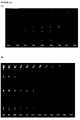
- FIGS. 10A and 10Bshow the image of Hela cells in the V-grooves at several focal planes in DAPI and Cytokeratin-PE treated cells, respectively.
- Panel Ashows several Hela cells aligned vertically for different points of focus within the cell. The numbers represent the values as obtained from imaging, indicating the point of focus in micrometers, using DAPI.
- Panel Bshown the same with the phycoeurthrin (PE) labeled cytokeratin.
- PEphycoeurthrin
- FIGS. 11A and 11Bshows a diagram comparing microstructures.
- Panel Ashows the V-groove structure formed from a PDMS mold.
- Panel Bshows the foxhole structure having an improved image quality by allowing the cells to concentrate at the flat surface.
- Target specimenssuch as cells, cell debris, and cell components are collected against a collection surface of a vessel without subsequent alignment adjacent to a ferromagnetic collection structure.
- These cellsinclude white blood cells, cells of epithelial origin, endothelial cells, fungal cells, and bacterial cells.
- the collection surfaceis oriented perpendicular to a magnetic field gradient produced by external magnets.
- magnetic nanoparticles and magnetically labeled biological specimensare collected in a substantially homogeneous distribution on the optically transparent face of the chamber while non-selected entities remain below in the fluid medium. This result can be accomplished by placing a chamber in a gap between two magnets arranged as shown in FIG.
- the magnets 3have a thickness of 3 mm, and are tapered toward a gap of 3 mm.
- the magnets 3are held in a yoke 1 , which rests atop a housing 2 .
- a vessel support 4holds the vessel 6 in a region between the magnets where the lines of magnetic force are directed substantially perpendicular to the collection surface 5 of the vessel 6 .
- the collection surface of the vesselis preferably formed of a 0.1 mm thick polycarbonate member.
- the collection surfaceis parallel to, and 2 mm below, the upper surface of the external magnets 3 .
- the space between the inner, top surface edges of the magnetsis 3 mm.
- the taper angle of the magnets 3 and the width of the gap between the two magnetsdetermine the magnitude of the applied magnetic field gradient and the preferable position of the collection surface of the vessel.
- the field gradient produced by the magnetscan be characterized as having a substantially uniform region, wherein the gradient field lines are substantially parallel, and fringing regions, wherein the gradient field lines diverge toward the magnets.
- FIG. 1Bshows mathematically approximated magnetic field gradient lines for such a magnet arrangement.
- the magnetic field lines(not shown) are predominantly parallel to the chamber surface while the gradient lines are predominantly perpendicular to it.
- the vesselis positioned to place the chamber in the uniform region such that there are substantially no transverse magnetic gradient components which would cause lateral transport of the magnetically labeled biological specimens to the collection surface.
- a chamber with inner dimensions of 2.5 mm height (z), 3 mm width (x) and 30 mm length (y)was filled with 225 ⁇ l of a solution containing 150 nm diameter magnetic beads and placed in between the magnets as illustrated in FIG. 1A .
- the magnetic beadsmoved to the collection surface and were distributed evenly.
- the surface materialcan be selected or otherwise treated to have an adhesive attraction for the collected species.
- horizontal drifting of the collected species due to any deviations in positioning the chamber of deviations from the desired perpendicular magnetic gradients in the “substantially uniform” regioncan be eliminated.
- FIG. 2illustrates an example of the use of the magnets and the chamber without the influence of a capture structure on the collection surface to localize, differentiate and enumerate peripheral blood selected epithelial derived tumor cells.
- the buffer containing the detergentwas discarded and the vessel was taken out of the separator and the cells collected at the wall were resuspended in 200 ⁇ l of a buffer containing the UV excitable nucleic acid dye DAPI (Molecular Probes) and Cytokeratin monoclonal antibodies (identifying epithelial cells) labeled with the fluorochrome Cy3.
- DAPIUV excitable nucleic acid dye
- Cytokeratin monoclonal antibodiesidentifying epithelial cells labeled with the fluorochrome Cy3.
- the cellswere incubated for 15 minutes after which the vessel was placed in the separator. After 5 minutes the uncollected fraction containing excess reagents was discarded, the vessel was taken out of the separator and the collected cells were resuspended in 200 ⁇ l of an isotonic buffer. This solution was placed into a collection chamber and placed in the magnetic separator shown in FIG. 1A .
- FIG. 2AThe ferrofluid labeled cells and the free ferrofluid particles moved immediately to the collection surface and were evenly distributed along the surface as is shown in FIG. 2A .
- the figureshows a representative area on the collection surface using transmitted light and a 20 ⁇ objective.
- FIG. 2Bthe same field is shown but now a filter cube is used for Cy3 excitation and emission. Two objects can be identified and are indicated with 1 and 2 .
- FIG. 2Cshows the same field but the filter cube is switched to one with an excitation and emission filter cube for DAPI.
- the objects at position 1 and 2both stain with DAPI as indicated at positions 3 and 5 confirm their identity as epithelial cells. Additional non epithelial cells and other cell elements cells are identified by the DAPI stain; an example is indicated by the number 4 .
- V-groovesare long v-shaped grooves, pre-molded into the inner portion of the viewing surface on the imaging chamber. These structures provide an alignment of cells as good as or even better than previously reported Ni lines. Furthermore, V-grooves are made from a highly transparent material, optically suited for imaging the entire cell. A schematic drawing of the V-grooves together with the alignment principle of the Ni lines, for comparison, is shown in FIG. 3 .
- FIG. 3illustrates the principle of cell alignment using V-grooves.
- Magnetically induced cell movement in the chamberis similar to Ni lines, except at the inner surface of the sample chamber.
- the magnetically labeled cellswill either collide with the inclined surface of the V-grooves and slide into the top of the groove (indicated in the above Figure by L), or they will directly hit the top of the V-groove. In either situation, the cells will align in the groove, allowing for subsequent imaging.
- V-groovesetched onto a silicon wafer, are the inverse of the eventual design, and provide the PDMS mold with the correct V-groove shape when poured onto the silicon mold. After curing, this shape is cut into dimensions that would allow replacement of the glass surface of the imaging chamber.
- the height of the chamber in concert with the concentration of the target entitydetermines the density of the distribution of target specimens collected at the collection surface of a vessel such as described above.
- concentrationmay vary widely.
- FIG. 4Aa cross section of a chamber is shown with a collection surface 1 , and six compartments having different heights. Target cells are randomly positioned in the chamber.
- FIG. 4Bthe same cross section is shown but now the cells have moved to the collection surface under the influence of the magnetic gradient.
- Etchingcan be accomplished on any optically transparent material that can be used in the manufacture of the chamber.
- silicon waferscan be used in etching because of the ease of precision, fine detail, and reproducability. Any material with similar characteristics and known in the art is considered in the present invention.
- Etching of the V-groove shapesuses two common etching techniques. First an etch mask that is needed to etch the grooves is created. This mask is created using BHF (Buffered Hydrofluoric acid) etching. The process of BHF etching is explained in FIG. 5 . Once BHF etching is complete, thin layers of SiO 2 are left on the silicon wafer at places where no V-groove should be etched.
- BHFBand Hydrofluoric acid
- Anisotropic etchingis also used to etch the V-grooves.
- KOHis used as etchant.
- etchantused as etchant.
- a highly reproducible and constant etch angleis produced. The angle depends on the wafer orientation with one embodiment at a constant 35.26 degrees.
- DRIEDeep Reactive Ion Etching
- PDMS moldingis used to obtain a positive imprint on the fabricated wafer.
- PDMS or Polydimethylsiloxane(Dow Corning (Sylgard 184, Dow Corning, Midland, Mich., USA) is a polymer containing the siloxane bond between Si (Silicon) and O (Oxygen). The polymers molecules are linked together to form longer polymers with an average number around 50 to 100.
- the final PDMSis obtained with the addition of a cross-linker.
- the cross-linkerconnects with the polymers to form long networks of polymers, resulting in a clear, elastic, chemically inert, thermally stable material.
- the PDMSforms a clear flexible substance which adheres to very few materials and is not hygroscopic, thus preventing any sticking of cells to the sides due to the fact that PDMS adheres to very few materials.
- itis thermally stable and transparent from approximately 300 to 900 nm. These characteristics are all important for its use in a fluorescent imaging system and the transmission of visible light.
- FIG. 6illustrates the relationship between the wafer, PDMS mold and the formation of the V-grooves. After formation the V-grooves are cut into the dimensions of the viewing face of the chamber.
- FIG. 7depicts the transmission spectrum through the viewing surface.
- VParameters of the V-Groove Viewing Surface and Examples of Use
- Lis the width of the flat horizontal area and D is the spacing of the grooves. Varying L will influence the alignment of the cells in the groove. If L is too big, cells may overlap or may be not perfectly aligned in the center. Misalignment influences scanning and imaging, complicating subsequent image analysis. As a consequence, the size of the laser spot has to be increased so as to match the increased area that has to be illuminated.
- the spacing of the groovesis controlled by D. This influences the maximum cell size and the number of cells that can be accommodated.
- FIG. 9One possible example of a wafer design incorporates a chimney-like design ( FIG. 9 ). This design accommodates the excess ferrofluid in solution to a position away from the cells. This design were fabricated using DRIE high aspect ratio etching. The width of the chimneys should be smaller than the smallest diameter of an interested cell.
- Hela cellsare labeled with Cytokeratin-PE ( FIG. 10A ) and DAPI ( FIG. 10B ) to fluorescently stain the nucleus and the cytoskeleton. These cells were tested in a chamber fitted with a V-groove structure on the viewing surface. Cells labeled with both cytokeratin-PE and DAPI were imaged at several focal points along the V-groove. At 200 ⁇ m, the top of the V-groove is in focus. Lower values indicate a lower point of focus.
- PDMSpoly-dimethyl siloxane
- These microstructuresare produced by making PDMS molds of etched silicon wafers.
- the unique properties of PDMSmake it an excellent material to use for these microstructures. It is optically transparent down to 300 nm, can easily be glued to supporting structures and is cost effective. Furthermore, structures can be replicated with sub-micron accuracy and adhesion of cells to the material is low.
- a forceis needed; e.g. gravity or a magnetic force.
- the latteris used in the CellTracks® system, a Circulating Tumor Cell analysis system, to align cells in the microstructures. Characterization of these cells is done by scanning them with 4 homogenized laserspots. Essential properties of two microstructures like alignment and image quality were investigated using SKBR3 cells. They were immuno-magnetically labeled and aligned in the structures by a magnetic field. FIG. 11 gives an overview drawing of the two microstructures.
- the first structurearranges the cells in a long line, like in Flow Cytometry, and is suited for cell counting.
- Cellsare illuminated and imaged from the top of the structures shown in the figure.
- Image quality in the V-Grooveis reduced by light diffraction at the tip of the V-Groove.
- the image qualityis improved in the Foxhole structure were the cells are concentrated at a flat surface. Alignment efficiency of both structures is greater than 97%.
- Array orientation (2D grid)is also possible (not shown in figure) in square and hexagonal packing.
- the V-Grooveoffers excellent alignment and good quantitative properties.
- the Foxhole microstructureoffers good alignment and excellent image quality. It allows the illumination area to be matched to the channel width in the CellTracks system, thereby reducing scanning times by a factor of 3.
Landscapes
- Health & Medical Sciences (AREA)
- Life Sciences & Earth Sciences (AREA)
- Organic Chemistry (AREA)
- Engineering & Computer Science (AREA)
- Bioinformatics & Cheminformatics (AREA)
- Chemical & Material Sciences (AREA)
- Zoology (AREA)
- Wood Science & Technology (AREA)
- Sustainable Development (AREA)
- Microbiology (AREA)
- Biotechnology (AREA)
- Biomedical Technology (AREA)
- Biochemistry (AREA)
- General Engineering & Computer Science (AREA)
- General Health & Medical Sciences (AREA)
- Genetics & Genomics (AREA)
- Molecular Biology (AREA)
- Apparatus Associated With Microorganisms And Enzymes (AREA)
Abstract
Description
Claims (14)
Priority Applications (1)
| Application Number | Priority Date | Filing Date | Title |
|---|---|---|---|
| US11/447,562US7666308B2 (en) | 1996-06-07 | 2006-06-06 | Magnetic separation apparatus and methods |
Applications Claiming Priority (7)
| Application Number | Priority Date | Filing Date | Title |
|---|---|---|---|
| US1928296P | 1996-06-07 | 1996-06-07 | |
| US3043696P | 1996-11-05 | 1996-11-05 | |
| US08/867,009US5985153A (en) | 1996-06-07 | 1997-06-02 | Magnetic separation apparatus and methods employing an internal magnetic capture gradient and an external transport force |
| US09/201,603US6136182A (en) | 1996-06-07 | 1998-11-30 | Magnetic devices and sample chambers for examination and manipulation of cells |
| US10/602,979US6790366B2 (en) | 1996-06-07 | 2003-06-24 | Magnetic separation apparatus and methods |
| US10/733,829US6890426B2 (en) | 1996-06-07 | 2003-12-10 | Magnetic separation apparatus and methods |
| US11/447,562US7666308B2 (en) | 1996-06-07 | 2006-06-06 | Magnetic separation apparatus and methods |
Related Parent Applications (1)
| Application Number | Title | Priority Date | Filing Date |
|---|---|---|---|
| US10/733,829Continuation-In-PartUS6890426B2 (en) | 1996-06-07 | 2003-12-10 | Magnetic separation apparatus and methods |
Publications (2)
| Publication Number | Publication Date |
|---|---|
| US20060257847A1 US20060257847A1 (en) | 2006-11-16 |
| US7666308B2true US7666308B2 (en) | 2010-02-23 |
Family
ID=37419561
Family Applications (1)
| Application Number | Title | Priority Date | Filing Date |
|---|---|---|---|
| US11/447,562Expired - Fee RelatedUS7666308B2 (en) | 1996-06-07 | 2006-06-06 | Magnetic separation apparatus and methods |
Country Status (1)
| Country | Link |
|---|---|
| US (1) | US7666308B2 (en) |
Cited By (16)
| Publication number | Priority date | Publication date | Assignee | Title |
|---|---|---|---|---|
| US20110059468A1 (en)* | 2009-09-09 | 2011-03-10 | Earhart Christopher M | Magnetic separation device for cell sorting and analysis |
| US8710836B2 (en) | 2008-12-10 | 2014-04-29 | Nanomr, Inc. | NMR, instrumentation, and flow meter/controller continuously detecting MR signals, from continuously flowing sample material |
| US8790916B2 (en) | 2009-05-14 | 2014-07-29 | Genestream, Inc. | Microfluidic method and system for isolating particles from biological fluid |
| US8841104B2 (en) | 2010-04-21 | 2014-09-23 | Nanomr, Inc. | Methods for isolating a target analyte from a heterogeneous sample |
| US8956536B2 (en) | 2012-10-26 | 2015-02-17 | Becton, Dickinson And Company | Devices and methods for manipulating components in a fluid sample |
| US9389225B2 (en) | 2010-04-21 | 2016-07-12 | Dna Electronics, Inc. | Separating target analytes using alternating magnetic fields |
| US9428547B2 (en) | 2010-04-21 | 2016-08-30 | Dna Electronics, Inc. | Compositions for isolating a target analyte from a heterogeneous sample |
| US9476812B2 (en) | 2010-04-21 | 2016-10-25 | Dna Electronics, Inc. | Methods for isolating a target analyte from a heterogeneous sample |
| US9551704B2 (en) | 2012-12-19 | 2017-01-24 | Dna Electronics, Inc. | Target detection |
| US9599610B2 (en) | 2012-12-19 | 2017-03-21 | Dnae Group Holdings Limited | Target capture system |
| US9804069B2 (en) | 2012-12-19 | 2017-10-31 | Dnae Group Holdings Limited | Methods for degrading nucleic acid |
| US9885642B2 (en) | 2011-04-27 | 2018-02-06 | Becton, Dickinson And Company | Devices and methods for separating magnetically labeled moieties in a sample |
| US9902949B2 (en) | 2012-12-19 | 2018-02-27 | Dnae Group Holdings Limited | Methods for universal target capture |
| US9995742B2 (en) | 2012-12-19 | 2018-06-12 | Dnae Group Holdings Limited | Sample entry |
| US10000557B2 (en) | 2012-12-19 | 2018-06-19 | Dnae Group Holdings Limited | Methods for raising antibodies |
| US12133327B2 (en) | 2019-05-06 | 2024-10-29 | 3M Innovative Properties Company | Patterned article including electrically conductive elements |
Families Citing this family (6)
| Publication number | Priority date | Publication date | Assignee | Title |
|---|---|---|---|---|
| US7479123B2 (en) | 2002-03-04 | 2009-01-20 | Therakos, Inc. | Method for collecting a desired blood component and performing a photopheresis treatment |
| CN202011883U (en)* | 2007-12-12 | 2011-10-19 | 里兰斯坦福初级大学理事会 | Device for capturing and separating target cell |
| US20110127222A1 (en)* | 2008-03-19 | 2011-06-02 | Cynvenio Biosystems, Inc. | Trapping magnetic cell sorting system |
| EP2271919A1 (en)* | 2008-04-16 | 2011-01-12 | Cynvenio Biosystems, Inc. | Magnetic separation system with pre and post processing modules |
| US8569077B2 (en)* | 2008-05-19 | 2013-10-29 | Veridex, Llc | Imaging of immunomagnetically enriched rare cells |
| EP2440941B1 (en)* | 2009-06-10 | 2017-05-31 | Cynvenio Biosystems, Inc. | Sheath flow devices and methods |
Citations (20)
| Publication number | Priority date | Publication date | Assignee | Title |
|---|---|---|---|---|
| US4729949A (en) | 1982-05-10 | 1988-03-08 | Bar-Ilan University | System and methods for cell selection |
| US4735504A (en) | 1983-10-31 | 1988-04-05 | Technicon Instruments Corporation | Method and apparatus for determining the volume & index of refraction of particles |
| US4989978A (en) | 1986-04-04 | 1991-02-05 | Technicon Instruments Corporation | Method and apparatus for determining the count per unit volume of particles |
| US5030560A (en) | 1988-11-04 | 1991-07-09 | Immucor, Inc. | Method for drying mammalian cells for use in solid phase immunoassays and articles incorporating same |
| US5053344A (en) | 1987-08-04 | 1991-10-01 | Cleveland Clinic Foundation | Magnetic field separation and analysis system |
| US5200084A (en) | 1990-09-26 | 1993-04-06 | Immunicon Corporation | Apparatus and methods for magnetic separation |
| WO1994011078A1 (en)* | 1992-11-16 | 1994-05-26 | Immunivest Corporation | Magnetic immobilization and manipulation of biological entities |
| US5340749A (en) | 1988-04-26 | 1994-08-23 | Nippon Telegraph And Telephone Corporation | Method for collecting and preparing specimens for immune reactions |
| US5375606A (en) | 1990-02-28 | 1994-12-27 | Zynaxis, Inc. | Bio-analytical separation method |
| US5411863A (en) | 1988-12-28 | 1995-05-02 | S. Miltenyi | Methods and materials for improved high gradient magnetic separation of biological materials |
| US5428451A (en) | 1989-12-07 | 1995-06-27 | Diatec Instruments A/S | Process and apparatus for counting particles |
| US5451525A (en) | 1992-02-14 | 1995-09-19 | Coulter Corporation | Method and materials for determining particle count in a flow cytometer |
| US5466574A (en) | 1991-03-25 | 1995-11-14 | Immunivest Corporation | Apparatus and methods for magnetic separation featuring external magnetic means |
| US5494831A (en) | 1993-08-30 | 1996-02-27 | Hughes Aircraft Company | Electrochemical immunosensor system and methods |
| US5541072A (en) | 1994-04-18 | 1996-07-30 | Immunivest Corporation | Method for magnetic separation featuring magnetic particles in a multi-phase system |
| US5646001A (en) | 1991-03-25 | 1997-07-08 | Immunivest Corporation | Affinity-binding separation and release of one or more selected subset of biological entities from a mixed population thereof |
| US5985153A (en) | 1996-06-07 | 1999-11-16 | Immunivest Corporation | Magnetic separation apparatus and methods employing an internal magnetic capture gradient and an external transport force |
| US6013532A (en) | 1990-09-26 | 2000-01-11 | Immunivest Corporation | Methods for magnetic immobilization and manipulation of cells |
| US6790366B2 (en)* | 1996-06-07 | 2004-09-14 | Immunivest Corporation | Magnetic separation apparatus and methods |
| US6890426B2 (en)* | 1996-06-07 | 2005-05-10 | Immunivest Corporation | Magnetic separation apparatus and methods |
Family Cites Families (2)
| Publication number | Priority date | Publication date | Assignee | Title |
|---|---|---|---|---|
| JP2001043231A (en)* | 1999-07-29 | 2001-02-16 | Toshiba Corp | File management system, electronic filing system and file hierarchical structure display method |
| US7412433B2 (en)* | 2002-11-19 | 2008-08-12 | International Business Machines Corporation | Hierarchical storage management using dynamic tables of contents and sets of tables of contents |
- 2006
- 2006-06-06USUS11/447,562patent/US7666308B2/ennot_activeExpired - Fee Related
Patent Citations (21)
| Publication number | Priority date | Publication date | Assignee | Title |
|---|---|---|---|---|
| US4729949A (en) | 1982-05-10 | 1988-03-08 | Bar-Ilan University | System and methods for cell selection |
| US4735504A (en) | 1983-10-31 | 1988-04-05 | Technicon Instruments Corporation | Method and apparatus for determining the volume & index of refraction of particles |
| US4989978A (en) | 1986-04-04 | 1991-02-05 | Technicon Instruments Corporation | Method and apparatus for determining the count per unit volume of particles |
| US5053344A (en) | 1987-08-04 | 1991-10-01 | Cleveland Clinic Foundation | Magnetic field separation and analysis system |
| US5498550A (en) | 1988-04-26 | 1996-03-12 | Nippon Telegraph & Telephone Corporation | Device for collecting or preparing specimens using magnetic micro-particles |
| US5340749A (en) | 1988-04-26 | 1994-08-23 | Nippon Telegraph And Telephone Corporation | Method for collecting and preparing specimens for immune reactions |
| US5030560A (en) | 1988-11-04 | 1991-07-09 | Immucor, Inc. | Method for drying mammalian cells for use in solid phase immunoassays and articles incorporating same |
| US5411863A (en) | 1988-12-28 | 1995-05-02 | S. Miltenyi | Methods and materials for improved high gradient magnetic separation of biological materials |
| US5428451A (en) | 1989-12-07 | 1995-06-27 | Diatec Instruments A/S | Process and apparatus for counting particles |
| US5375606A (en) | 1990-02-28 | 1994-12-27 | Zynaxis, Inc. | Bio-analytical separation method |
| US5200084A (en) | 1990-09-26 | 1993-04-06 | Immunicon Corporation | Apparatus and methods for magnetic separation |
| US6013532A (en) | 1990-09-26 | 2000-01-11 | Immunivest Corporation | Methods for magnetic immobilization and manipulation of cells |
| US5466574A (en) | 1991-03-25 | 1995-11-14 | Immunivest Corporation | Apparatus and methods for magnetic separation featuring external magnetic means |
| US5646001A (en) | 1991-03-25 | 1997-07-08 | Immunivest Corporation | Affinity-binding separation and release of one or more selected subset of biological entities from a mixed population thereof |
| US5451525A (en) | 1992-02-14 | 1995-09-19 | Coulter Corporation | Method and materials for determining particle count in a flow cytometer |
| WO1994011078A1 (en)* | 1992-11-16 | 1994-05-26 | Immunivest Corporation | Magnetic immobilization and manipulation of biological entities |
| US5494831A (en) | 1993-08-30 | 1996-02-27 | Hughes Aircraft Company | Electrochemical immunosensor system and methods |
| US5541072A (en) | 1994-04-18 | 1996-07-30 | Immunivest Corporation | Method for magnetic separation featuring magnetic particles in a multi-phase system |
| US5985153A (en) | 1996-06-07 | 1999-11-16 | Immunivest Corporation | Magnetic separation apparatus and methods employing an internal magnetic capture gradient and an external transport force |
| US6790366B2 (en)* | 1996-06-07 | 2004-09-14 | Immunivest Corporation | Magnetic separation apparatus and methods |
| US6890426B2 (en)* | 1996-06-07 | 2005-05-10 | Immunivest Corporation | Magnetic separation apparatus and methods |
Cited By (33)
| Publication number | Priority date | Publication date | Assignee | Title |
|---|---|---|---|---|
| US8710836B2 (en) | 2008-12-10 | 2014-04-29 | Nanomr, Inc. | NMR, instrumentation, and flow meter/controller continuously detecting MR signals, from continuously flowing sample material |
| US8790916B2 (en) | 2009-05-14 | 2014-07-29 | Genestream, Inc. | Microfluidic method and system for isolating particles from biological fluid |
| US20110059468A1 (en)* | 2009-09-09 | 2011-03-10 | Earhart Christopher M | Magnetic separation device for cell sorting and analysis |
| US8481336B2 (en) | 2009-09-09 | 2013-07-09 | The Board Of Trustees Of The Leland Stanford Junior University | Magnetic separation device for cell sorting and analysis |
| US8841104B2 (en) | 2010-04-21 | 2014-09-23 | Nanomr, Inc. | Methods for isolating a target analyte from a heterogeneous sample |
| US11448646B2 (en) | 2010-04-21 | 2022-09-20 | Dnae Group Holdings Limited | Isolating a target analyte from a body fluid |
| US9389225B2 (en) | 2010-04-21 | 2016-07-12 | Dna Electronics, Inc. | Separating target analytes using alternating magnetic fields |
| US9428547B2 (en) | 2010-04-21 | 2016-08-30 | Dna Electronics, Inc. | Compositions for isolating a target analyte from a heterogeneous sample |
| US9476812B2 (en) | 2010-04-21 | 2016-10-25 | Dna Electronics, Inc. | Methods for isolating a target analyte from a heterogeneous sample |
| US11073513B2 (en) | 2010-04-21 | 2021-07-27 | Dnae Group Holdings Limited | Separating target analytes using alternating magnetic fields |
| US10677789B2 (en) | 2010-04-21 | 2020-06-09 | Dnae Group Holdings Limited | Analyzing bacteria without culturing |
| US9562896B2 (en) | 2010-04-21 | 2017-02-07 | Dnae Group Holdings Limited | Extracting low concentrations of bacteria from a sample |
| US9869671B2 (en) | 2010-04-21 | 2018-01-16 | Dnae Group Holdings Limited | Analyzing bacteria without culturing |
| US9671395B2 (en) | 2010-04-21 | 2017-06-06 | Dnae Group Holdings Limited | Analyzing bacteria without culturing |
| US9696302B2 (en) | 2010-04-21 | 2017-07-04 | Dnae Group Holdings Limited | Methods for isolating a target analyte from a heterogeneous sample |
| US9970931B2 (en) | 2010-04-21 | 2018-05-15 | Dnae Group Holdings Limited | Methods for isolating a target analyte from a heterogenous sample |
| US10444125B2 (en) | 2011-04-27 | 2019-10-15 | Becton, Dickinson And Company | Devices and methods for separating magnetically labeled moieties in a sample |
| US9885642B2 (en) | 2011-04-27 | 2018-02-06 | Becton, Dickinson And Company | Devices and methods for separating magnetically labeled moieties in a sample |
| US9835540B2 (en) | 2012-10-26 | 2017-12-05 | Becton, Dickinson And Company | Devices and methods for manipulating components in a fluid sample |
| US8956536B2 (en) | 2012-10-26 | 2015-02-17 | Becton, Dickinson And Company | Devices and methods for manipulating components in a fluid sample |
| US9513205B2 (en) | 2012-10-26 | 2016-12-06 | Becton, Dickinson And Company | Devices and methods for manipulating components in a fluid sample |
| US9995742B2 (en) | 2012-12-19 | 2018-06-12 | Dnae Group Holdings Limited | Sample entry |
| US10000557B2 (en) | 2012-12-19 | 2018-06-19 | Dnae Group Holdings Limited | Methods for raising antibodies |
| US10379113B2 (en) | 2012-12-19 | 2019-08-13 | Dnae Group Holdings Limited | Target detection |
| US9599610B2 (en) | 2012-12-19 | 2017-03-21 | Dnae Group Holdings Limited | Target capture system |
| US10584329B2 (en) | 2012-12-19 | 2020-03-10 | Dnae Group Holdings Limited | Methods for universal target capture |
| US9551704B2 (en) | 2012-12-19 | 2017-01-24 | Dna Electronics, Inc. | Target detection |
| US10745763B2 (en) | 2012-12-19 | 2020-08-18 | Dnae Group Holdings Limited | Target capture system |
| US11016086B2 (en) | 2012-12-19 | 2021-05-25 | Dnae Group Holdings Limited | Sample entry |
| US9804069B2 (en) | 2012-12-19 | 2017-10-31 | Dnae Group Holdings Limited | Methods for degrading nucleic acid |
| US9902949B2 (en) | 2012-12-19 | 2018-02-27 | Dnae Group Holdings Limited | Methods for universal target capture |
| US11603400B2 (en) | 2012-12-19 | 2023-03-14 | Dnae Group Holdings Limited | Methods for raising antibodies |
| US12133327B2 (en) | 2019-05-06 | 2024-10-29 | 3M Innovative Properties Company | Patterned article including electrically conductive elements |
Also Published As
| Publication number | Publication date |
|---|---|
| US20060257847A1 (en) | 2006-11-16 |
Similar Documents
| Publication | Publication Date | Title |
|---|---|---|
| US7666308B2 (en) | Magnetic separation apparatus and methods | |
| WO2005061075A1 (en) | Magnetic separation apparatus and methods | |
| US8569077B2 (en) | Imaging of immunomagnetically enriched rare cells | |
| US6790366B2 (en) | Magnetic separation apparatus and methods | |
| US6660159B1 (en) | Magnetic separation apparatus and methods | |
| JP2011521262A5 (en) | ||
| US6623983B1 (en) | Apparatus and methods for capture and analysis of particulate entities | |
| US8189899B2 (en) | Methods and algorithms for cell enumeration in a low-cost cytometer | |
| US8481336B2 (en) | Magnetic separation device for cell sorting and analysis | |
| JP2000513437A (en) | Magnetic separation with external and internal gradients | |
| KR20140004207A (en) | Particle processing | |
| US10032615B2 (en) | Systems and methods for single cell culture and analysis by microscopy and MALDI mass spectrometry | |
| CA2352064C (en) | Magnetic separation apparatus and methods | |
| US20070199901A1 (en) | Method And Device For Division Of A Biological Sample By Magnetic Effect | |
| CA2533683C (en) | Magnetic separation apparatus and methods | |
| JP4593672B2 (en) | Magnetic separator and method thereof | |
| Cai | A single-cell assay and a biosample enrichment method for analyzing single cell secretion | |
| WO1996007913A1 (en) | Diagnostic apparatus | |
| Gach | Capturing, analyzing and collecting adherent cells using microarray technologies |
Legal Events
| Date | Code | Title | Description |
|---|---|---|---|
| AS | Assignment | Owner name:VERIDEX, LLC, NEW JERSEY Free format text:ASSIGNMENT OF ASSIGNORS INTEREST;ASSIGNOR:IMMUNICON CORP.;REEL/FRAME:021334/0454 Effective date:20080731 Owner name:VERIDEX, LLC,NEW JERSEY Free format text:ASSIGNMENT OF ASSIGNORS INTEREST;ASSIGNOR:IMMUNICON CORP.;REEL/FRAME:021334/0454 Effective date:20080731 | |
| AS | Assignment | Owner name:VERIDEX, LLC, NEW JERSEY Free format text:ASSIGNMENT OF ASSIGNORS INTEREST;ASSIGNORS:SCHOLTENS, TYCHO M.;TERSTAPPEN, LEON W.M.M.;TIBBE, ARJAN G.J.;REEL/FRAME:022481/0335 Effective date:20090120 Owner name:VERIDEX, LLC,NEW JERSEY Free format text:ASSIGNMENT OF ASSIGNORS INTEREST;ASSIGNORS:SCHOLTENS, TYCHO M.;TERSTAPPEN, LEON W.M.M.;TIBBE, ARJAN G.J.;REEL/FRAME:022481/0335 Effective date:20090120 | |
| STCF | Information on status: patent grant | Free format text:PATENTED CASE | |
| CC | Certificate of correction | ||
| FPAY | Fee payment | Year of fee payment:4 | |
| AS | Assignment | Owner name:JANSSEN DIAGNOSTICS, LLC, NEW JERSEY Free format text:CHANGE OF NAME;ASSIGNOR:VERIDEX, LLC;REEL/FRAME:031970/0554 Effective date:20130528 | |
| FEPP | Fee payment procedure | Free format text:MAINTENANCE FEE REMINDER MAILED (ORIGINAL EVENT CODE: REM.) | |
| FEPP | Fee payment procedure | Free format text:7.5 YR SURCHARGE - LATE PMT W/IN 6 MO, LARGE ENTITY (ORIGINAL EVENT CODE: M1555) | |
| MAFP | Maintenance fee payment | Free format text:PAYMENT OF MAINTENANCE FEE, 8TH YEAR, LARGE ENTITY (ORIGINAL EVENT CODE: M1552) Year of fee payment:8 | |
| AS | Assignment | Owner name:MENARINI SILICON BIOSYSTEMS, INC., CALIFORNIA Free format text:ASSIGNMENT OF ASSIGNORS INTEREST;ASSIGNOR:JANSSEN DIAGNOSTICS, LLC;REEL/FRAME:045238/0050 Effective date:20171026 | |
| AS | Assignment | Owner name:MENARINI SILICON BIOSYSTEMS S.P.A., ITALY Free format text:NUNC PRO TUNC ASSIGNMENT;ASSIGNOR:MENARINI SILICON BIOSYSTEMS, INC.;REEL/FRAME:049631/0823 Effective date:20181219 | |
| FEPP | Fee payment procedure | Free format text:MAINTENANCE FEE REMINDER MAILED (ORIGINAL EVENT CODE: REM.); ENTITY STATUS OF PATENT OWNER: LARGE ENTITY | |
| LAPS | Lapse for failure to pay maintenance fees | Free format text:PATENT EXPIRED FOR FAILURE TO PAY MAINTENANCE FEES (ORIGINAL EVENT CODE: EXP.); ENTITY STATUS OF PATENT OWNER: LARGE ENTITY | |
| STCH | Information on status: patent discontinuation | Free format text:PATENT EXPIRED DUE TO NONPAYMENT OF MAINTENANCE FEES UNDER 37 CFR 1.362 | |
| FP | Lapsed due to failure to pay maintenance fee | Effective date:20220223 |