US7666208B1 - Posterior cervical vertebral stabilizing system - Google Patents
Posterior cervical vertebral stabilizing systemDownload PDFInfo
- Publication number
- US7666208B1 US7666208B1US11/120,522US12052205AUS7666208B1US 7666208 B1US7666208 B1US 7666208B1US 12052205 AUS12052205 AUS 12052205AUS 7666208 B1US7666208 B1US 7666208B1
- Authority
- US
- United States
- Prior art keywords
- vertebra
- posterior
- lower portion
- upper portion
- legs
- Prior art date
- Legal status (The legal status is an assumption and is not a legal conclusion. Google has not performed a legal analysis and makes no representation as to the accuracy of the status listed.)
- Expired - Lifetime, expires
Links
Images


Classifications
- A—HUMAN NECESSITIES
- A61—MEDICAL OR VETERINARY SCIENCE; HYGIENE
- A61B—DIAGNOSIS; SURGERY; IDENTIFICATION
- A61B17/00—Surgical instruments, devices or methods
- A61B17/56—Surgical instruments or methods for treatment of bones or joints; Devices specially adapted therefor
- A61B17/58—Surgical instruments or methods for treatment of bones or joints; Devices specially adapted therefor for osteosynthesis, e.g. bone plates, screws or setting implements
- A61B17/68—Internal fixation devices, including fasteners and spinal fixators, even if a part thereof projects from the skin
- A61B17/70—Spinal positioners or stabilisers, e.g. stabilisers comprising fluid filler in an implant
- A61B17/7062—Devices acting on, attached to, or simulating the effect of, vertebral processes, vertebral facets or ribs ; Tools for such devices
- A61B17/7067—Devices bearing against one or more spinous processes and also attached to another part of the spine; Tools therefor
- A—HUMAN NECESSITIES
- A61—MEDICAL OR VETERINARY SCIENCE; HYGIENE
- A61B—DIAGNOSIS; SURGERY; IDENTIFICATION
- A61B17/00—Surgical instruments, devices or methods
- A61B17/56—Surgical instruments or methods for treatment of bones or joints; Devices specially adapted therefor
- A61B17/58—Surgical instruments or methods for treatment of bones or joints; Devices specially adapted therefor for osteosynthesis, e.g. bone plates, screws or setting implements
- A61B17/68—Internal fixation devices, including fasteners and spinal fixators, even if a part thereof projects from the skin
- A61B17/70—Spinal positioners or stabilisers, e.g. stabilisers comprising fluid filler in an implant
- A61B17/7053—Spinal positioners or stabilisers, e.g. stabilisers comprising fluid filler in an implant with parts attached to bones or to each other by flexible wires, straps, sutures or cables
Definitions
- the present inventionrelates to spinal stabilization systems and more particularly pertains to a new posterior cervical vertebral stabilizing system including an apparatus and a method of employing the apparatus for not only stabilizing adjacent vertebrae with respect to each other, but also optionally facilitating fusion of the adjacent vertebrae.
- Serious types of fractures of the vertebra of the spinal column of the human bodyinclude a fracture at the interface between the first cervical (C 1 ) vertebra, or “atlas”, and the second cervical (C 2 ) vertebra, or “axis”.
- the C 2 vertebraincludes an upstanding protrusion referred to as the odontoid process, or dens, about which the generally annular C 1 vertebra extends.
- a fracture of the odontoid process, and especially a type two fracture of the odontoid processis often treated by posterior atlanto-axial arthrodesis, which generally is intended to stabilize the C 1 and C 2 vertebrae with respect to each other and promote fusion of the vertebrae.
- Known techniques for treating such fracturesinclude internal stabilization of the C 1 and C 2 vertebra with respect to each other, using posterior C 1 -C 2 transarticular facet screw fixation, which carries with it the risk of injury to the vertebral artery or the spinal cord.
- Another approach for treating such fracturesis through interspinous wiring with interposition of a bone graft, which carries with it a high incidence of pseudoarthrosis, or non-healing of the bone employed for fusion.
- the posterior cervical vertebral stabilizing systemsubstantially departs from the conventional concepts and designs and techniques of the prior art.
- the present inventionprovides a new posterior cervical vertebral stabilizing system that can be utilized not only for stabilizing adjacent vertebrae with respect to each other, but also for facilitating fusion of the adjacent vertebrae.
- a posterior cervical vertebral stabilizing devicecomprises an upper portion for positioning adjacent to a relatively superior vertebra of a patient's spine and a lower portion for positioning adjacent to a relatively inferior vertebra of the patient's spine.
- the upper portionforms a support for abutting the posterior surface of the superior vertebra and the lower portion forms a saddle for engaging a spinous process of the inferior vertebra.
- the devicehas an anterior face that, at each of the upper and lower portions, has a radius of curvature about an axis. In one highly preferred embodiment of the device, the radius of curvature of the anterior face at the upper portion is larger than the radius of curvature of the anterior face at the lower portion.
- the deviceis affixed to a spine of a patient by positioning the device posteriorly of the relatively superior and relatively inferior vertebrae, and looping cable about the device and the lamina of the vertebrae.
- the methodmay also include promoting fusion of the vertebrae together by harvesting cancellous bone from the patient's body, applying the harvested cancellous bone over the exposed lateral masses of the relatively superior and relatively inferior vertebrae, placing the harvested cancellous bone between the spinous processes and lamina of the inferior vertebra and the posterior arch of the superior vertebra, and placing the harvested cancellous bone in the aperture of the device.
- One significant advantage of the present inventionis the intimate relationship that is possible between the device and the surfaces of the vertebrae to thereby form a very stable construct on the vertebrae, so that cancellous bone placed on and about the vertebrae and the device has a high likelihood of forming a successful fusion of the vertebrae.
- FIG. 1is a schematic perspective view of the new posterior cervical vertebral stabilizing device according to the present invention.
- FIG. 2is a schematic side view of posterior cervical vertebral stabilizing device of the present invention.
- FIG. 3is a schematic bottom end view of posterior cervical vertebral stabilizing device of the present invention.
- FIG. 4is a schematic top end view of posterior cervical vertebral stabilizing device of the present invention.
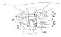
- FIG. 5is a schematic posterior view of the device of the present invention shown mounted on the superior and inferior vertebrae of the spine.
- FIG. 6is a schematic lateral view of the device of the present invention shown mounted on the superior and inferior vertebrae of the spine.
- FIGS. 1 through 6With reference now to the drawings, and in particular to FIGS. 1 through 6 thereof, a new posterior cervical vertebral stabilizing system embodying the principles and concepts of the present invention will be described.
- the posterior cervical vertebral stabilizing system of the inventionincludes a posterior cervical vertebral stabilizing device 10 for mounting on adjacent vertebrae of the spine of the patient, and the system of the invention also includes a method of utilizing the device 10 to stabilize the adjacent vertebrae with respect to each other.
- the posterior cervical vertebral stabilizing device 10 of the inventionis highly suitable for stabilizing adjacent vertebrae with respect to each other.
- the device 10comprises an upper portion 12 which may be positioned adjacent to a relatively superior vertebra 2 of a patient's spine 1 , and also includes a lower portion 14 which may be positioned adjacent to a relatively inferior vertebra 4 of the patient's spine (see FIGS. 5 and 6 ).
- the device 10has a posterior face 16 for positioning away from the spine of the patient, and an anterior face 18 for positioning toward and adjacent to the patient's spine.
- the anterior face 18 of the device 10may be curved or generally concave in shape for following, to a significant degree, the curvature of the superior 2 and inferior 4 vertebrae.
- the anterior face 18 at the upper portion 12 of the devicehas a greater or more severe curvature than the anterior face at the lower portion 14 of the device.
- the anterior face 18has a radius of curvature at each of the upper 12 and lower 14 portions.
- the radius of curvature of the upper portion 12may be greater, or relatively longer, than the radius of curvature of the lower portion 14 (see FIG.
- the concavity or relative curvature of the upper portion 12may be of a relatively lesser or smaller degree in order to conform better and more intimately to the posterior arch of the C 1 vertebra, and the concavity or relative curvature of the lower portion 14 may be of a relatively greater degree in order to conform better and more intimately to the lamina of the C 2 vertebra.
- the device 10 of the inventionhas a top 20 for orienting upwardly on the patient and a bottom 22 for orienting downwardly on the patient.
- the device 10also has lateral sides 24 , 25 that extend between the top 20 and bottom 22 , and the lateral sides may be oriented substantially parallel to each other.
- the upper portion 12 of the device 10may form a support 26 for abutting or resting against the posterior surface 3 of the relatively superior vertebra 2
- the lower portion 14may form a saddle 28 for positioning adjacent to, and optionally engaging, the spinous process 6 or posterior protrusion of the relatively inferior vertebra 4 .
- the lower portion 14 of the device 10may form an arch 30 for positioning substantially superiorly to and about a portion of the spinous process 6 of the relatively inferior vertebra.
- the lower portion 14may include a pair of legs 32 , 34 for positioning on opposite sides of the spinous process 6 of the relatively inferior vertebra, and the arch 30 may extend substantially transversely between the respective upper sections 36 , 38 of the legs 32 , 34 .
- the arch 30may have an inferior surface 40 , and each of the legs 32 , 34 may have a respective inner edge 42 , 44 .
- the inner edges 42 , 44 of the legsmay converge toward each other in a superior or upward direction when positioned for implantation in the body, and may diverge away from each other in an inferior or downward direction.
- Each of the legs 32 , 34may have a respective distal tip section 46 , 48 .
- the curvature of the anterior face 18 of the device 10 described abovemay be such that a portion of the anterior face on the leg 32 is oriented at an angle to a portion of the anterior face on the of the leg 34 (see, e.g., FIG. 3 ).
- the anglemay be in the range of approximately 80 degrees to approximately 120 degrees, and in one embodiment measures approximately 90 degrees
- the upper portion 12 of the device 10may have a bridge 54 that extends between the lateral sides 24 , 25 .
- the upper portion 12may also have a pair of lateral side extents 60 , 62 , with each of the lateral side extents extending between one of the legs 32 , 34 and the bridge 54 .
- the bridge 54 , the arch 30 , and the lateral side extents 60 , 62may define an interior aperture 64 therebetween.
- a number of grooves or notchesmay be provided on the device 10 .
- the bridge 54may have a cable-receiving groove, and may have a pair of grooves 56 , 58 , that extend from the anterior face 18 to the posterior face 16 of the device 10 .
- each distal tip section 46 , 48 of a respective legmay have a respective cable-receiving groove 50 , 52 formed therein that extends from the anterior face 18 to the posterior face 16 .
- the lower portion 14may have a notch 66 , 68 positioned in an upper section of each of the respective legs 32 , 34 , and each of the notches may be in communication with the aperture 64 .
- the device 10 of the inventionmay be relatively elongated from top 20 to bottom 22 to a greater degree to permit extension of the device between three, four, or even more vertebrae of the spinal column for stabilizing three, four, or more vertebrae with respect to each other, and optionally for fusion of the three, four, or more vertebrae.
- Another aspect of the system of the inventionis a method of performing a posterior atlanto-axial arthrodesis that may most suitably be performed using the posterior vertebral stabilizing device of the system.
- the posterior cervical vertebral stabilizing device 10is affixed to the spine 1 of a patient.
- the device 10may be positioned posteriorly of the relatively superior vertebra 2 and the relatively inferior vertebra 4 of the spine 1 , and may be abutted against the posterior surfaces of the relatively superior and relatively inferior vertebra.
- the deviceis attached to the first cervical (C 1 ) vertebra, or atlas, and the second cervical (C 2 ) vertebra, or axis, for stabilizing, and preferably fusing, these vertebrae with respect to each other.
- the bridge 54 of the device 10is positioned posteriorly of the posterior arch of the C 1 vertebra, and may extend about the posterior tubercle of the C 1 vertebra.
- the lower portion 14 of the device 10is positioned posteriorly of the lamina of the C 2 vertebra, with the legs being positioned on either side of the spinous process 6 .
- the arch 30 and legs 32 , 34 of the devicemay embrace and surround a significant portion of the spinous process of the C 2 vertebra, and the bridge 54 extends along (in a generally parallel fashion) a portion of the posterior arch of the C 1 vertebra.
- the curvature of the anterior face 18 of the device 10facilitates the positioning and the abutment of the device in a close and intimate relationship with the posterior surfaces of the vertebrae.
- the affixation of the device to the vertebrae of the spinal columnmay be performed by looping an elongate flexible member, such as stainless steel or titanium cable, about portions of the device and portions of lamina of the vertebrae 2 , 4 (see FIG. 5 ).
- an elongate flexible membersuch as stainless steel or titanium cable
- four lengths 70 , 72 , 74 , 76 of cableare looped about portions of the device and portions of the vertebra.
- a first length 70 of cablemay be looped about the device 10 and the lamina of the relatively inferior vertebra 4 , and the first length may be extended through the cable-receiving groove 50 and the notch 66 of the first leg 32 .
- a second length 72 of cablemay be looped about the device 10 and the relatively inferior vertebra 4 with the second length being extended through the cable-receiving groove 52 and the notch 68 of the second leg 34 .
- a third length 74 of cablemay be looped about the device 10 and the lamina of the relatively superior vertebra 2 , and the third length may be extended through the cable-receiving groove 56 of the bridge 54 of the device.
- a fourth length 76 of cablemay be looped about the device 10 and the lamina of the relatively superior vertebra 2 with the third length extended through the cable-receiving groove 58 of the bridge 54 of the device.
- the method of the systemmay also include the promotion of fusion of the relatively superior vertebra 2 to the relatively inferior vertebra 4 .
- Bone materialmay be harvested from the patient's body, such as cancellous bone taken from the iliac crest of the patient.
- the harvested cancellous bonemay be applied over the exposed lateral masses of the relatively superior and relatively inferior vertebrae, and may also be placed between the spinous processes and lamina of the inferior vertebra 4 and the posterior arch of the superior vertebra 6 .
- the harvested cancellous bonemay also be placed in the aperture 64 of the device 10 mounted on the vertebral column.
Landscapes
- Health & Medical Sciences (AREA)
- Orthopedic Medicine & Surgery (AREA)
- Life Sciences & Earth Sciences (AREA)
- Neurology (AREA)
- Surgery (AREA)
- Heart & Thoracic Surgery (AREA)
- Engineering & Computer Science (AREA)
- Biomedical Technology (AREA)
- Nuclear Medicine, Radiotherapy & Molecular Imaging (AREA)
- Medical Informatics (AREA)
- Molecular Biology (AREA)
- Animal Behavior & Ethology (AREA)
- General Health & Medical Sciences (AREA)
- Public Health (AREA)
- Veterinary Medicine (AREA)
- Surgical Instruments (AREA)
- Prostheses (AREA)
Abstract
Description
Claims (21)
Priority Applications (1)
| Application Number | Priority Date | Filing Date | Title |
|---|---|---|---|
| US11/120,522US7666208B1 (en) | 2005-04-29 | 2005-04-29 | Posterior cervical vertebral stabilizing system |
Applications Claiming Priority (1)
| Application Number | Priority Date | Filing Date | Title |
|---|---|---|---|
| US11/120,522US7666208B1 (en) | 2005-04-29 | 2005-04-29 | Posterior cervical vertebral stabilizing system |
Publications (1)
| Publication Number | Publication Date |
|---|---|
| US7666208B1true US7666208B1 (en) | 2010-02-23 |
Family
ID=41692143
Family Applications (1)
| Application Number | Title | Priority Date | Filing Date |
|---|---|---|---|
| US11/120,522Expired - LifetimeUS7666208B1 (en) | 2005-04-29 | 2005-04-29 | Posterior cervical vertebral stabilizing system |
Country Status (1)
| Country | Link |
|---|---|
| US (1) | US7666208B1 (en) |
Cited By (14)
| Publication number | Priority date | Publication date | Assignee | Title |
|---|---|---|---|---|
| US20090240283A1 (en)* | 2008-03-18 | 2009-09-24 | Warsaw Orthopedic, Inc. | Implants and methods for inter-spinous process dynamic stabilization of a spinal motion segment |
| US20110106163A1 (en)* | 2006-01-23 | 2011-05-05 | Hochschuler Stephen H | Interlaminar Stabilizing System |
| US8262697B2 (en) | 2010-01-14 | 2012-09-11 | X-Spine Systems, Inc. | Modular interspinous fixation system and method |
| WO2012145971A1 (en)* | 2011-04-26 | 2012-11-01 | 西安交通大学 | Artificial atlanto-odontoid joint |
| US8764830B2 (en)* | 2009-09-11 | 2014-07-01 | Articulinx, Inc. | Disc-shaped orthopedic devices |
| US9592083B2 (en) | 2013-08-30 | 2017-03-14 | New South Innovations Pty Limited | Spine stabilization device |
| CN106510821A (en)* | 2014-10-24 | 2017-03-22 | 邹玉华 | Orthopedic fixing support and use method thereof |
| US9931143B2 (en) | 2012-08-31 | 2018-04-03 | New South Innovations Pty Limited | Bone stabilization device and methods of use |
| US9987052B2 (en) | 2015-02-24 | 2018-06-05 | X-Spine Systems, Inc. | Modular interspinous fixation system with threaded component |
| US10034693B2 (en) | 2016-07-07 | 2018-07-31 | Mark S. Stern | Spinous laminar clamp assembly |
| US10456174B2 (en) | 2017-07-31 | 2019-10-29 | Medos International Sarl | Connectors for use in systems and methods for reducing the risk of proximal junctional kyphosis |
| US10463403B2 (en) | 2017-07-31 | 2019-11-05 | Medos International Sarl | Systems and methods for reducing the risk of proximal junctional kyphosis using a bone anchor or other attachment point |
| US11389209B2 (en) | 2019-07-19 | 2022-07-19 | Medos International Sarl | Surgical plating systems, devices, and related methods |
| US20240307129A1 (en)* | 2021-08-04 | 2024-09-19 | University Of Florida Research Foundation, Incorporated | Neurosurgical navigation system reference array apparatus |
Citations (18)
| Publication number | Priority date | Publication date | Assignee | Title |
|---|---|---|---|---|
| US4369769A (en) | 1980-06-13 | 1983-01-25 | Edwards Charles C | Spinal fixation device and method |
| EP0140790A2 (en) | 1983-10-28 | 1985-05-08 | William Peze | Apparatus for the dynamic correction of rachidian deformations |
| US4570618A (en) | 1983-11-23 | 1986-02-18 | Henry Ford Hospital | Intervertebral body wire stabilization |
| US4604995A (en) | 1984-03-30 | 1986-08-12 | Stephens David C | Spinal stabilizer |
| US4836193A (en)* | 1986-11-05 | 1989-06-06 | A. W. Showell (Surgicraft) Limited | Skull to spine fixation device |
| EP0322334A1 (en) | 1987-12-23 | 1989-06-28 | Cremascoli France | Prosthesis implanted between vertebral spinous processes |
| WO1991016018A1 (en) | 1989-02-03 | 1991-10-31 | Francis Henri Breard | Flexible intervertebral stabilizer, and method and apparatus for determining or controlling its tension before it is placed on the back bone |
| US5306275A (en) | 1992-12-31 | 1994-04-26 | Bryan Donald W | Lumbar spine fixation apparatus and method |
| US5413576A (en) | 1993-02-10 | 1995-05-09 | Rivard; Charles-Hilaire | Apparatus for treating spinal disorder |
| US5725582A (en) | 1992-08-19 | 1998-03-10 | Surgicraft Limited | Surgical implants |
| US5733284A (en) | 1993-08-27 | 1998-03-31 | Paulette Fairant | Device for anchoring spinal instrumentation on a vertebra |
| US5879385A (en)* | 1993-06-11 | 1999-03-09 | Hillway Surgical Limited | Surgical implant |
| USRE36221E (en) | 1989-02-03 | 1999-06-01 | Breard; Francis Henri | Flexible inter-vertebral stabilizer as well as process and apparatus for determining or verifying its tension before installation on the spinal column |
| US5928232A (en) | 1994-11-16 | 1999-07-27 | Advanced Spine Fixation Systems, Incorporated | Spinal fixation system |
| EP1046347A1 (en) | 1998-01-08 | 2000-10-25 | Otsuka Foods Co., Ltd. | Gelled foods and process for producing the same |
| US6190387B1 (en) | 1997-01-02 | 2001-02-20 | St. Francis Medical Technologies, Inc. | Spine distraction implant |
| US20060241610A1 (en)* | 2005-04-08 | 2006-10-26 | Sdgi Holdings, Inc. | Interspinous process spacer |
| US20060241757A1 (en)* | 2005-03-31 | 2006-10-26 | Sdgi Holdings, Inc. | Intervertebral prosthetic device for spinal stabilization and method of manufacturing same |
- 2005
- 2005-04-29USUS11/120,522patent/US7666208B1/ennot_activeExpired - Lifetime
Patent Citations (18)
| Publication number | Priority date | Publication date | Assignee | Title |
|---|---|---|---|---|
| US4369769A (en) | 1980-06-13 | 1983-01-25 | Edwards Charles C | Spinal fixation device and method |
| EP0140790A2 (en) | 1983-10-28 | 1985-05-08 | William Peze | Apparatus for the dynamic correction of rachidian deformations |
| US4570618A (en) | 1983-11-23 | 1986-02-18 | Henry Ford Hospital | Intervertebral body wire stabilization |
| US4604995A (en) | 1984-03-30 | 1986-08-12 | Stephens David C | Spinal stabilizer |
| US4836193A (en)* | 1986-11-05 | 1989-06-06 | A. W. Showell (Surgicraft) Limited | Skull to spine fixation device |
| EP0322334A1 (en) | 1987-12-23 | 1989-06-28 | Cremascoli France | Prosthesis implanted between vertebral spinous processes |
| USRE36221E (en) | 1989-02-03 | 1999-06-01 | Breard; Francis Henri | Flexible inter-vertebral stabilizer as well as process and apparatus for determining or verifying its tension before installation on the spinal column |
| WO1991016018A1 (en) | 1989-02-03 | 1991-10-31 | Francis Henri Breard | Flexible intervertebral stabilizer, and method and apparatus for determining or controlling its tension before it is placed on the back bone |
| US5725582A (en) | 1992-08-19 | 1998-03-10 | Surgicraft Limited | Surgical implants |
| US5306275A (en) | 1992-12-31 | 1994-04-26 | Bryan Donald W | Lumbar spine fixation apparatus and method |
| US5413576A (en) | 1993-02-10 | 1995-05-09 | Rivard; Charles-Hilaire | Apparatus for treating spinal disorder |
| US5879385A (en)* | 1993-06-11 | 1999-03-09 | Hillway Surgical Limited | Surgical implant |
| US5733284A (en) | 1993-08-27 | 1998-03-31 | Paulette Fairant | Device for anchoring spinal instrumentation on a vertebra |
| US5928232A (en) | 1994-11-16 | 1999-07-27 | Advanced Spine Fixation Systems, Incorporated | Spinal fixation system |
| US6190387B1 (en) | 1997-01-02 | 2001-02-20 | St. Francis Medical Technologies, Inc. | Spine distraction implant |
| EP1046347A1 (en) | 1998-01-08 | 2000-10-25 | Otsuka Foods Co., Ltd. | Gelled foods and process for producing the same |
| US20060241757A1 (en)* | 2005-03-31 | 2006-10-26 | Sdgi Holdings, Inc. | Intervertebral prosthetic device for spinal stabilization and method of manufacturing same |
| US20060241610A1 (en)* | 2005-04-08 | 2006-10-26 | Sdgi Holdings, Inc. | Interspinous process spacer |
Non-Patent Citations (5)
| Title |
|---|
| Johnson & Johnson, Codman TI-FRAME Posterior Cervical Stabilization System Technique Guide (15 pgs). |
| Johnson &Johnson, Codman TI-FRAME For Posterior Cervical Stabilization (1 pg). |
| Wheeles Textbook of Orthopaedics , Posterior Atlanto-Axial Arthrodesis Oct. 17, 2002 (1 pg). |
| Wheeles Textbook of Orthopaedics, Dens Fracture Oct. 17, 2002 (2pgs). |
| Wheeles Textbook of Orthopaedics, Type 2 Dens Frx Oct. 17, 2002 (2pgs). |
Cited By (31)
| Publication number | Priority date | Publication date | Assignee | Title |
|---|---|---|---|---|
| US20110106163A1 (en)* | 2006-01-23 | 2011-05-05 | Hochschuler Stephen H | Interlaminar Stabilizing System |
| US8758409B2 (en)* | 2006-01-23 | 2014-06-24 | Pioneer Surgical Technology, Inc. | Interlaminar stabilizing system |
| US20090240283A1 (en)* | 2008-03-18 | 2009-09-24 | Warsaw Orthopedic, Inc. | Implants and methods for inter-spinous process dynamic stabilization of a spinal motion segment |
| US8764830B2 (en)* | 2009-09-11 | 2014-07-01 | Articulinx, Inc. | Disc-shaped orthopedic devices |
| US8262697B2 (en) | 2010-01-14 | 2012-09-11 | X-Spine Systems, Inc. | Modular interspinous fixation system and method |
| US8932333B2 (en) | 2010-01-14 | 2015-01-13 | X-Spine Systems, Inc. | Modular interspinous fixation system and method |
| US9439689B2 (en) | 2010-01-14 | 2016-09-13 | X-Spine Systems, Inc. | Modular interspinous fixation system and method |
| WO2012145971A1 (en)* | 2011-04-26 | 2012-11-01 | 西安交通大学 | Artificial atlanto-odontoid joint |
| US9931143B2 (en) | 2012-08-31 | 2018-04-03 | New South Innovations Pty Limited | Bone stabilization device and methods of use |
| US9592083B2 (en) | 2013-08-30 | 2017-03-14 | New South Innovations Pty Limited | Spine stabilization device |
| US11413075B2 (en) | 2013-08-30 | 2022-08-16 | New South Innovations Pty Limited | Spine stabilization device |
| US10441323B2 (en) | 2013-08-30 | 2019-10-15 | New South Innovations Pty Limited | Spine stabilization device |
| CN106510820B (en)* | 2014-10-24 | 2019-06-18 | 刘扬 | Orthopedic fixing support |
| CN106510820A (en)* | 2014-10-24 | 2017-03-22 | 邹玉华 | Fixing support used in department of orthopedics |
| CN106725781A (en)* | 2014-10-24 | 2017-05-31 | 邹玉华 | A kind of vertebra bone anchor and its application method |
| CN106510819A (en)* | 2014-10-24 | 2017-03-22 | 邹玉华 | Using method for orthopaedic fixing bracket |
| CN106725779A (en)* | 2014-10-24 | 2017-05-31 | 邹玉华 | Vertebra bone anchor |
| CN106725781B (en)* | 2014-10-24 | 2019-02-01 | 江苏艾迪尔医疗科技股份有限公司 | A kind of vertebra bone anchor and its application method |
| CN106725779B (en)* | 2014-10-24 | 2019-03-05 | 苏州苏南捷迈得医疗器械有限公司 | Vertebra bone anchor |
| CN106510821A (en)* | 2014-10-24 | 2017-03-22 | 邹玉华 | Orthopedic fixing support and use method thereof |
| CN106510819B (en)* | 2014-10-24 | 2019-06-21 | 张秀静 | The application method of Orthopedic fixing support |
| US9987052B2 (en) | 2015-02-24 | 2018-06-05 | X-Spine Systems, Inc. | Modular interspinous fixation system with threaded component |
| US10034693B2 (en) | 2016-07-07 | 2018-07-31 | Mark S. Stern | Spinous laminar clamp assembly |
| US10456174B2 (en) | 2017-07-31 | 2019-10-29 | Medos International Sarl | Connectors for use in systems and methods for reducing the risk of proximal junctional kyphosis |
| US10463403B2 (en) | 2017-07-31 | 2019-11-05 | Medos International Sarl | Systems and methods for reducing the risk of proximal junctional kyphosis using a bone anchor or other attachment point |
| US11207107B2 (en) | 2017-07-31 | 2021-12-28 | Medos International Sarl | Systems and methods for reducing the risk of proximal junctional kyphosis using a bone anchor or other attachment point |
| US11298158B2 (en) | 2017-07-31 | 2022-04-12 | Medos International Sarl | Connectors for use in systems and methods for reducing the risk of proximal junctional kyphosis |
| US12336740B2 (en) | 2017-07-31 | 2025-06-24 | Medos International Sárl | Systems and methods for reducing the risk of proximal junctional kyphosis using a bone anchor or other attachment point |
| US12349943B2 (en) | 2017-07-31 | 2025-07-08 | Medos International Sàrl | Connectors for use in systems and methods for reducing the risk of proximal junctional kyphosis |
| US11389209B2 (en) | 2019-07-19 | 2022-07-19 | Medos International Sarl | Surgical plating systems, devices, and related methods |
| US20240307129A1 (en)* | 2021-08-04 | 2024-09-19 | University Of Florida Research Foundation, Incorporated | Neurosurgical navigation system reference array apparatus |
Similar Documents
| Publication | Publication Date | Title |
|---|---|---|
| US11826080B2 (en) | Occipital plate systems | |
| US5562662A (en) | Spinal fixation system and method | |
| US7666208B1 (en) | Posterior cervical vertebral stabilizing system | |
| US11690654B2 (en) | Adjustable fixation device | |
| US8636771B2 (en) | Spinal implants for lumbar vertebra to sacrum fixation | |
| EP1729664B1 (en) | Head-to-head connector spinal fixation system | |
| US20050080415A1 (en) | Polyaxial bone anchor and method of spinal fixation | |
| US20110106168A1 (en) | Laminoplasty Rod System | |
| US9492206B2 (en) | Interspinous ligament transverse connector | |
| US10667852B2 (en) | Laminar fixation clamp and method | |
| KR101643961B1 (en) | Pedicle screw devices | |
| US7947063B2 (en) | Posterior-medial facet support assembly | |
| US20110245879A1 (en) | Method of connecting transverse beam at triangular position of vertebral lamina |
Legal Events
| Date | Code | Title | Description |
|---|---|---|---|
| AS | Assignment | Owner name:ASFORA IP, LLC,SOUTH DAKOTA Free format text:ASSIGNMENT OF ASSIGNORS INTEREST;ASSIGNOR:ASFORA, WILSON T.;REEL/FRAME:018797/0539 Effective date:20061227 | |
| FPAY | Fee payment | Year of fee payment:4 | |
| FEPP | Fee payment procedure | Free format text:MAINTENANCE FEE REMINDER MAILED (ORIGINAL EVENT CODE: REM.) | |
| LAPS | Lapse for failure to pay maintenance fees | Free format text:PATENT EXPIRED FOR FAILURE TO PAY MAINTENANCE FEES (ORIGINAL EVENT CODE: EXP.) | |
| PRDP | Patent reinstated due to the acceptance of a late maintenance fee | Effective date:20180417 | |
| FEPP | Fee payment procedure | Free format text:SURCHARGE, PETITION TO ACCEPT PYMT AFTER EXP, UNINTENTIONAL. (ORIGINAL EVENT CODE: M2558); ENTITY STATUS OF PATENT OWNER: SMALL ENTITY Free format text:PETITION RELATED TO MAINTENANCE FEES GRANTED (ORIGINAL EVENT CODE: PMFG) Free format text:PETITION RELATED TO MAINTENANCE FEES FILED (ORIGINAL EVENT CODE: PMFP) | |
| FP | Lapsed due to failure to pay maintenance fee | Effective date:20180223 | |
| MAFP | Maintenance fee payment | Free format text:PAYMENT OF MAINTENANCE FEE, 8TH YR, SMALL ENTITY (ORIGINAL EVENT CODE: M2552) Year of fee payment:8 | |
| STCF | Information on status: patent grant | Free format text:PATENTED CASE | |
| MAFP | Maintenance fee payment | Free format text:PAYMENT OF MAINTENANCE FEE, 12TH YR, SMALL ENTITY (ORIGINAL EVENT CODE: M2553); ENTITY STATUS OF PATENT OWNER: SMALL ENTITY Year of fee payment:12 |