US7665972B2 - Apparatus and method for controlling operation of reciprocating compressor - Google Patents
Apparatus and method for controlling operation of reciprocating compressorDownload PDFInfo
- Publication number
- US7665972B2 US7665972B2US11/019,287US1928704AUS7665972B2US 7665972 B2US7665972 B2US 7665972B2US 1928704 AUS1928704 AUS 1928704AUS 7665972 B2US7665972 B2US 7665972B2
- Authority
- US
- United States
- Prior art keywords
- operating frequency
- reciprocating compressor
- reference value
- current
- compressor
- Prior art date
- Legal status (The legal status is an assumption and is not a legal conclusion. Google has not performed a legal analysis and makes no representation as to the accuracy of the status listed.)
- Expired - Fee Related, expires
Links
Images


Classifications
- F—MECHANICAL ENGINEERING; LIGHTING; HEATING; WEAPONS; BLASTING
- F04—POSITIVE - DISPLACEMENT MACHINES FOR LIQUIDS; PUMPS FOR LIQUIDS OR ELASTIC FLUIDS
- F04B—POSITIVE-DISPLACEMENT MACHINES FOR LIQUIDS; PUMPS
- F04B49/00—Control, e.g. of pump delivery, or pump pressure of, or safety measures for, machines, pumps, or pumping installations, not otherwise provided for, or of interest apart from, groups F04B1/00 - F04B47/00
- F04B49/06—Control using electricity
- F04B49/065—Control using electricity and making use of computers
- F—MECHANICAL ENGINEERING; LIGHTING; HEATING; WEAPONS; BLASTING
- F04—POSITIVE - DISPLACEMENT MACHINES FOR LIQUIDS; PUMPS FOR LIQUIDS OR ELASTIC FLUIDS
- F04B—POSITIVE-DISPLACEMENT MACHINES FOR LIQUIDS; PUMPS
- F04B35/00—Piston pumps specially adapted for elastic fluids and characterised by the driving means to their working members, or by combination with, or adaptation to, specific driving engines or motors, not otherwise provided for
- F04B35/04—Piston pumps specially adapted for elastic fluids and characterised by the driving means to their working members, or by combination with, or adaptation to, specific driving engines or motors, not otherwise provided for the means being electric
- F—MECHANICAL ENGINEERING; LIGHTING; HEATING; WEAPONS; BLASTING
- F04—POSITIVE - DISPLACEMENT MACHINES FOR LIQUIDS; PUMPS FOR LIQUIDS OR ELASTIC FLUIDS
- F04B—POSITIVE-DISPLACEMENT MACHINES FOR LIQUIDS; PUMPS
- F04B49/00—Control, e.g. of pump delivery, or pump pressure of, or safety measures for, machines, pumps, or pumping installations, not otherwise provided for, or of interest apart from, groups F04B1/00 - F04B47/00
- F04B49/12—Control, e.g. of pump delivery, or pump pressure of, or safety measures for, machines, pumps, or pumping installations, not otherwise provided for, or of interest apart from, groups F04B1/00 - F04B47/00 by varying the length of stroke of the working members
- F—MECHANICAL ENGINEERING; LIGHTING; HEATING; WEAPONS; BLASTING
- F25—REFRIGERATION OR COOLING; COMBINED HEATING AND REFRIGERATION SYSTEMS; HEAT PUMP SYSTEMS; MANUFACTURE OR STORAGE OF ICE; LIQUEFACTION SOLIDIFICATION OF GASES
- F25B—REFRIGERATION MACHINES, PLANTS OR SYSTEMS; COMBINED HEATING AND REFRIGERATION SYSTEMS; HEAT PUMP SYSTEMS
- F25B31/00—Compressor arrangements
- F25B31/02—Compressor arrangements of motor-compressor units
- F25B31/023—Compressor arrangements of motor-compressor units with compressor of reciprocating-piston type
- F—MECHANICAL ENGINEERING; LIGHTING; HEATING; WEAPONS; BLASTING
- F25—REFRIGERATION OR COOLING; COMBINED HEATING AND REFRIGERATION SYSTEMS; HEAT PUMP SYSTEMS; MANUFACTURE OR STORAGE OF ICE; LIQUEFACTION SOLIDIFICATION OF GASES
- F25B—REFRIGERATION MACHINES, PLANTS OR SYSTEMS; COMBINED HEATING AND REFRIGERATION SYSTEMS; HEAT PUMP SYSTEMS
- F25B49/00—Arrangement or mounting of control or safety devices
- F25B49/02—Arrangement or mounting of control or safety devices for compression type machines, plants or systems
- F25B49/022—Compressor control arrangements
- F—MECHANICAL ENGINEERING; LIGHTING; HEATING; WEAPONS; BLASTING
- F25—REFRIGERATION OR COOLING; COMBINED HEATING AND REFRIGERATION SYSTEMS; HEAT PUMP SYSTEMS; MANUFACTURE OR STORAGE OF ICE; LIQUEFACTION SOLIDIFICATION OF GASES
- F25B—REFRIGERATION MACHINES, PLANTS OR SYSTEMS; COMBINED HEATING AND REFRIGERATION SYSTEMS; HEAT PUMP SYSTEMS
- F25B49/00—Arrangement or mounting of control or safety devices
- F25B49/02—Arrangement or mounting of control or safety devices for compression type machines, plants or systems
- F25B49/025—Motor control arrangements
- H—ELECTRICITY
- H02—GENERATION; CONVERSION OR DISTRIBUTION OF ELECTRIC POWER
- H02P—CONTROL OR REGULATION OF ELECTRIC MOTORS, ELECTRIC GENERATORS OR DYNAMO-ELECTRIC CONVERTERS; CONTROLLING TRANSFORMERS, REACTORS OR CHOKE COILS
- H02P25/00—Arrangements or methods for the control of AC motors characterised by the kind of AC motor or by structural details
- H02P25/02—Arrangements or methods for the control of AC motors characterised by the kind of AC motor or by structural details characterised by the kind of motor
- H02P25/032—Reciprocating, oscillating or vibrating motors
- F—MECHANICAL ENGINEERING; LIGHTING; HEATING; WEAPONS; BLASTING
- F04—POSITIVE - DISPLACEMENT MACHINES FOR LIQUIDS; PUMPS FOR LIQUIDS OR ELASTIC FLUIDS
- F04B—POSITIVE-DISPLACEMENT MACHINES FOR LIQUIDS; PUMPS
- F04B2201/00—Pump parameters
- F04B2201/02—Piston parameters
- F04B2201/0206—Length of piston stroke
- F—MECHANICAL ENGINEERING; LIGHTING; HEATING; WEAPONS; BLASTING
- F04—POSITIVE - DISPLACEMENT MACHINES FOR LIQUIDS; PUMPS FOR LIQUIDS OR ELASTIC FLUIDS
- F04B—POSITIVE-DISPLACEMENT MACHINES FOR LIQUIDS; PUMPS
- F04B2203/00—Motor parameters
- F04B2203/04—Motor parameters of linear electric motors
- F04B2203/0401—Current
- F—MECHANICAL ENGINEERING; LIGHTING; HEATING; WEAPONS; BLASTING
- F04—POSITIVE - DISPLACEMENT MACHINES FOR LIQUIDS; PUMPS FOR LIQUIDS OR ELASTIC FLUIDS
- F04B—POSITIVE-DISPLACEMENT MACHINES FOR LIQUIDS; PUMPS
- F04B2203/00—Motor parameters
- F04B2203/04—Motor parameters of linear electric motors
- F04B2203/0402—Voltage
- F—MECHANICAL ENGINEERING; LIGHTING; HEATING; WEAPONS; BLASTING
- F04—POSITIVE - DISPLACEMENT MACHINES FOR LIQUIDS; PUMPS FOR LIQUIDS OR ELASTIC FLUIDS
- F04B—POSITIVE-DISPLACEMENT MACHINES FOR LIQUIDS; PUMPS
- F04B2207/00—External parameters
- F04B2207/04—Settings
- F04B2207/045—Settings of the resonant frequency of the unit motor-pump
Definitions
- the present inventionrelates to a reciprocating compressor, and more particularly to, an apparatus and a method for controlling an operation of a reciprocating compressor.
- a reciprocating compressorcompresses a refrigerant gas in a cylinder by linearly reciprocating a piston of the reciprocating compressor in the cylinder.
- the reciprocating compressoris classified into a rotary type reciprocating compressor and a linear type reciprocating compressor according to a method for driving a piston.
- a rotary motion of a rotary motoris transformed into a linear reciprocating motion of a piston by coupling a crank shaft to the rotary motor and coupling the piston to the crank shaft.
- a pistonis coupled directly to a mover of a linear motor, for linearly reciprocating on the basis of a linear reciprocating motion of the mover.
- the linear type reciprocating compressordoes not have a crank shaft for transforming a rotary motion into a linear reciprocating motion, and thus reduces a friction loss. Therefore, the linear type reciprocating compressor shows higher operational efficiency than the rotary type reciprocating compressor.
- the linear type reciprocating compressor(hereinafter, referred to as ‘compressor’) controls a stroke by controlling a voltage applied to a linear motor (hereinafter, referred to as ‘motor’) of the compressor according to a stroke reference value.
- a compression ratio of the compressorcan be adjusted.
- FIG. 1A conventional apparatus for controlling an operation of a compressor will now be explained with reference to FIG. 1 .
- FIG. 1is a block diagram illustrating the conventional apparatus for controlling the operation of the compressor.
- the conventional apparatus for controlling the operation of the compressorincludes: a voltage detection unit 140 for detecting a voltage applied to a motor; a current detection unit 150 for detecting a current applied to the motor; a stroke operator 160 for operating a stroke on the basis of the detected current value, the detected voltage value and parameters of the motor; a comparator 110 for comparing the operated stroke value with a stroke reference value, and outputting a difference value according to the comparison result; and a controller 120 for adjusting a compression ratio of the compressor 130 by controlling the stroke of the compressor 130 by controlling the voltage applied to the motor on the basis of the difference value.
- FIG. 2is a flowchart showing sequential steps of the conventional method for controlling the operation of the compressor.
- the conventional method for controlling the operation of the compressorincludes the steps of: detecting the voltage applied to the motor (S 201 ); detecting the current applied to the motor (S 202 ); operating the stroke on the basis of the detected current value, the detected voltage value and the parameters of the motor (S 203 ); comparing the operated stroke value with the stroke reference value, and outputting the comparison result (S 204 ); and controlling the stroke of the compressor by controlling the voltage applied to the motor according to the comparison result (S 205 and S 206 ).
- the voltage detection unit 140detects the voltage applied to the motor, and outputs the detected voltage value to the stroke operator 160 (S 201 ).
- the current detection unit 150detects the current applied to the motor, and outputs the detected current value to the stroke operator 160 (S 202 ).
- the stroke operator 160operates the stroke X by following formula 1 on the basis of the inputted current value, the inputted voltage value and the parameters of the motor (motor constant, resistance and inductance), and outputs the operation result to the comparator 110 (S 203 ).
- ⁇represents the motor constant
- V Mrepresents the voltage value detected in the motor
- irepresents the current value detected in the motor
- Rrepresents the resistance value of the motor
- Lrepresents the inductance value of the motor.
- the comparator 110compares the inputted stroke value with the stroke reference value, and outputs the comparison result to the controller 120 (S 204 ).
- the controller 120controls the voltage applied to the motor according to the inputted comparison result. That is, when the operated stroke value is smaller than the stroke reference value, the controller 120 increases the voltage applied to the motor (S 205 ), and when the operated stroke value is larger than the stroke reference value, the controller 120 decreases the voltage applied to the motor (S 206 ), thereby controlling the stroke of the compressor.
- the compressorhas a unique mechanical resonance frequency.
- FIG. 3is a graph showing the operational efficiency of the conventional compressor.
- an object of the present inventionis to provide an apparatus and a method for controlling an operation of a compressor which can improve operational efficiency of the compressor, by calculating a mechanical resonance frequency of the compressor whenever a load of the compressor is varied, generating an operating frequency reference value of the compressor on the basis of the calculated mechanical resonance frequency, and controlling an operating frequency of the compressor on the basis of the generated operating frequency reference value.
- an apparatus for controlling an operation of a compressorincluding: a resonance frequency calculating unit for calculating a mechanical resonance frequency of the compressor; an operating frequency reference value generation unit for comparing the calculated mechanical resonance frequency with a current operating frequency of the compressor, and generating an operating frequency reference value according to the comparison result; and a controller for controlling an operating frequency of the compressor according to the generated operating frequency reference value.
- a method for controlling an operation of a compressorincludes the steps of: calculating a mechanical resonance frequency of the compressor; comparing the calculated mechanical resonance frequency with a current operating frequency of the compressor, and generating an operating frequency reference value according to the comparison result; and controlling a current operating frequency according to the generated operating frequency reference value.
- FIG. 1is a block diagram illustrating a conventional apparatus for controlling an operation of a compressor
- FIG. 2is a flowchart showing sequential steps of a conventional method for controlling an operation of a compressor
- FIG. 3is a graph showing operational efficiency of the conventional compressor
- FIG. 4is a block diagram illustrating an apparatus for controlling an operation of a compressor in accordance with a first embodiment of the present invention
- FIGS. 5A and 5Bare flowcharts showing sequential steps of a method for controlling an operation of a compressor in accordance with the first embodiment of the present invention
- FIG. 6is a graph showing operational efficiency of the apparatus for controlling the operation of the compressor in accordance with the present invention.
- FIG. 7is a block diagram illustrating an apparatus for controlling an operation of a compressor in accordance with a second embodiment of the present invention.
- An apparatus and a method for controlling an operation of a compressorwhich can improve operational efficiency of the compressor by calculating a mechanical resonance frequency of the compressor whenever a load of the compressor is varied, generating an operating frequency reference value of the compressor on the basis of the calculated mechanical resonance frequency, and controlling a current operating frequency of the compressor on the basis of the generated operating frequency reference value will now be described in detail with reference to FIGS. 4 to 7 .
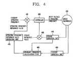
- FIG. 4is a block diagram illustrating an apparatus for controlling an operation of a compressor in accordance with a first embodiment of the present invention.
- the apparatus for controlling the operation of the compressorincludes: a stroke detection unit 440 for detecting a stroke of the compressor 430 ; a current detection unit 450 for detecting a current applied to a motor of the compressor 430 ; a resonance frequency calculating unit 460 for calculating a gas spring constant on the basis of the detected current value and the detected stroke value, and calculating a mechanical resonance frequency on the basis of the operated gas spring constant; an operating frequency reference value generation unit 470 for generating an operating frequency reference value on the basis of a difference value between the calculated mechanical resonance frequency and a current operating frequency of the compressor 430 ; a first comparator 410 for comparing the generated operating frequency reference value with the current operating frequency of the compressor 430 , and outputting a difference value according to the comparison result; a second comparator 480 for comparing the detected stroke value with a stroke reference value, and outputting a difference value according to the comparison result; and a controller 420 for controlling the stroke by controlling a voltage applied to the compressor 430
- FIGS. 5A and 5Bare flowcharts showing sequential steps of a method for controlling an operation of a compressor in accordance with the first embodiment of the present invention.
- the method for controlling the operation of the compressorincludes the steps of: detecting the current applied to the motor of the compressor 430 at an interval of a preset period (S 501 ); detecting the stroke of the compressor 430 at the interval of the preset period (S 502 ); calculating the gas spring constant k g on the basis of the detected stroke value and the detected current value (S 503 ); calculating the mechanical resonance frequency f m on the basis of the calculated gas spring constant k g (S 504 ); comparing the difference value between the current operating frequency f c of the compressor 430 and the calculated mechanical resonance frequency f m with a preset high efficiency operating frequency domain, and generating the operating frequency reference value according to the comparison result (S 505 to S 509 ); and controlling the current operating frequency according to the generated operating frequency reference value (S 510 to S 513 ).
- the current detection unit 450detects the current applied to the motor of the compressor 430 at the interval of the preset period, and outputs the detected current value to the resonance frequency operation unit 460 (S 501 ).
- the stroke detection unit 440detects the stroke of the compressor 430 at the interval of the preset period, and outputs the detected stroke value to the second comparator 480 and the resonance frequency operation unit 460 (S 502 ).
- the second comparator 480compares the inputted stroke value with the stroke reference value, and outputs the difference value to the controller 420 according to the comparison result.
- the controller 420controls the stroke by controlling the voltage applied the compressor 430 according to the inputted difference value.
- the resonance frequency calculating unit 460calculates the gas spring constant k g on the basis of the detected stroke value from the stroke detection unit 440 and the detected current value from the current detection unit 450 (S 503 ), calculates the mechanical resonance frequency f m on the basis of the calculated gas spring constant k g , and outputs the mechanical resonance frequency f m to the operating frequency reference value generation unit 470 (S 504 ).
- the gas spring constant k gis calculated by following formula 2
- the mechanical resonance frequency f mis calculated by following formula 3:
- ⁇represents the motor constant
- I(j ⁇ )represents the current value detected in the motor of the compressor
- X(j ⁇ )represents the stroke value detected in the compressor
- ⁇ i,xrepresents a phase difference between the current applied to the motor and the stroke detected in the compressor
- mrepresents a moving mass
- ⁇represents 2 ⁇ f c (f c is the current operating frequency of the compressor)
- k mrepresents a mechanical spring constant of the compressor.
- the operating frequency reference value generation unit 470compares the inputted mechanical resonance frequency f m with the current operating frequency f c , compares the resultant difference value with the preset high efficiency operating frequency domain, generates the operating frequency reference value according to the comparison result, and outputs the generated operating frequency reference value to the controller 420 (S 505 to S 509 ).
- the controller 420controls the compressor 430 by adjusting the operating frequency of the compressor 430 according to the inputted operating frequency reference value (S 510 to S 513 ).
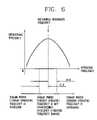
- FIG. 6is a graph showing operational efficiency of the apparatus for controlling the operation of the compressor in accordance with the present invention.
- the operating frequency reference value generation unit 470when the difference value obtained by subtracting the calculated mechanical resonance frequency f m from the current operating frequency f c exists within the preset high efficiency operating frequency domain 0 ⁇ , the operating frequency reference value generation unit 470 generates the current operating frequency f c as the operating frequency reference value as it is, and outputs the value to the controller 420 (S 505 , S 506 and S 509 ).
- the operating frequency reference value generation unit 470decreases the current operating frequency f c by a first preset level (S 505 and S 507 ), and when the difference value obtained by subtracting the calculated mechanical resonance frequency f m from the current operating frequency f c is smaller than a lower limit value 0 ⁇ of the preset high efficiency operating frequency domain, the operating frequency reference value generation unit 470 increases the current operating frequency f c by the first preset level (S 505 , S 506 and S 508 ).
- the operating frequency reference value generation unit 470controls the current operating frequency f c until the difference value obtained by subtracting the calculated mechanical resonance frequency f m from the current operating frequency f c exists within the preset high efficiency operating frequency domain 0+ ⁇ , generates the controlled value as the operating frequency reference value, and outputs the generated value to the controller 420 (S 509 ).
- the controller 420increases the current operating frequency by a second preset level (S 510 and S 512 ), and when the operating frequency reference value is smaller than the current operating frequency, the controller 420 decreases the current operating frequency by the second preset level (S 511 and S 513 ). Accordingly, the controller 420 controls the compressor 430 to maximize operational efficiency by equalizing the current operating frequency to the operating frequency reference value.
- the preset high efficiency operating frequency domainranges from 59.5 Hz to 60.5 Hz.
- the operating frequency reference value generation unit 470generates the current operating frequency as the operating frequency reference value.
- the operating frequency reference value generation unit 470increases the current operating frequency by the first preset level (for example, 0.5 Hz) until the value exists within the domain between 59.5 Hz and 60.5 Hz (58.7 Hz ⁇ 59.2 Hz ⁇ 59.7 Hz), and generates the increased value, 59.7 Hz as the operating frequency reference value.
- the first preset levelfor example, 0.5 Hz
- the controller 420increases the current operating frequency (58.7 Hz) by the second preset level (for example, 0.1 Hz) until the value reaches 59.7 Hz (58.7 Hz ⁇ 58.8 Hz ⁇ 58.9 Hz ⁇ . . . ⁇ 59.6 Hz ⁇ 59.7 Hz).
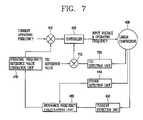
- FIG. 7is a block diagram illustrating the apparatus for controlling the operation of the compressor in accordance with the second embodiment of the present invention.
- the apparatus for controlling the operation of the compressorincludes: a stroke detection unit 440 for detecting a stroke of the compressor 430 ; a current detection unit 450 for detecting a current applied to a motor of the compressor 430 ; a resonance frequency calculating unit 460 for calculating a mechanical resonance frequency on the basis of the detected current value and the detected stroke value; an operating frequency reference value generation unit 470 for generating an operating frequency reference value on the basis of a difference value between the calculated mechanical resonance frequency and a current operating frequency of the compressor 430 ; a first comparator 410 for comparing the generated operating frequency reference value with the current operating frequency of the compressor 430 , and outputting a difference value according to the comparison result; a top dead center (TDC) detection unit 720 for detecting a TDC of the compressor 430 ; a third comparator 710 for comparing the detected TDC value with a TDC reference value, and outputting a difference value according to the comparison result; and a controller 420 for controlling the TDC by
- the current detection unit 450detects the current applied to the motor of the compressor 430 at the interval of the preset period, and outputs the detected current value to the resonance frequency operation unit 460 .
- the stroke detection unit 440detects the stroke of the compressor 430 at the interval of the preset period, and outputs the detected stroke value to the resonance frequency operation unit 460 .
- the TDC detection unit 720detects the TDC of the compressor 430 , and outputs the detected TDC value to the third comparator 710 .
- the third comparator 710compares the inputted TDC value with the TDC reference value, and outputs the difference value to the controller 420 according to the comparison result.
- the controller 420controls the TDC by controlling the voltage applied the compressor 430 according to the inputted difference value.
- the method for operating the operating frequency reference value, comparing the calculated operating frequency reference value with the current operating frequency, generating the operating frequency reference value according to the comparison result, and controlling the compressor on the basis of the generated operating frequency reference valueis identical to that of the first embodiment of the present invention, and thus detailed explanations thereof are omitted.
- the apparatus and the method for controlling the operation of the compressorcan improve operational efficiency of the compressor by calculating the mechanical resonance frequency of the compressor, and controlling the operating frequency so that the current operating frequency of the compressor can be equalized to the calculated mechanical resonance frequency.
Landscapes
- Engineering & Computer Science (AREA)
- Mechanical Engineering (AREA)
- General Engineering & Computer Science (AREA)
- Computer Hardware Design (AREA)
- Physics & Mathematics (AREA)
- Thermal Sciences (AREA)
- Power Engineering (AREA)
- Compressors, Vaccum Pumps And Other Relevant Systems (AREA)
- Control Of Positive-Displacement Pumps (AREA)
Abstract
Description
Claims (15)
Applications Claiming Priority (3)
| Application Number | Priority Date | Filing Date | Title |
|---|---|---|---|
| KR11481/2004 | 2004-01-20 | ||
| KR20040011481AKR100533041B1 (en) | 2004-02-20 | 2004-02-20 | Driving control apparatus and method for reciprocating compressor |
| KR10-2004-0011481 | 2004-02-20 |
Publications (2)
| Publication Number | Publication Date |
|---|---|
| US20050158178A1 US20050158178A1 (en) | 2005-07-21 |
| US7665972B2true US7665972B2 (en) | 2010-02-23 |
Family
ID=34747930
Family Applications (1)
| Application Number | Title | Priority Date | Filing Date |
|---|---|---|---|
| US11/019,287Expired - Fee RelatedUS7665972B2 (en) | 2004-02-20 | 2004-12-23 | Apparatus and method for controlling operation of reciprocating compressor |
Country Status (6)
| Country | Link |
|---|---|
| US (1) | US7665972B2 (en) |
| JP (1) | JP4081093B2 (en) |
| KR (1) | KR100533041B1 (en) |
| CN (1) | CN100417812C (en) |
| BR (1) | BRPI0405840A (en) |
| DE (1) | DE102004062665B4 (en) |
Cited By (3)
| Publication number | Priority date | Publication date | Assignee | Title |
|---|---|---|---|---|
| US20090202360A1 (en)* | 2004-10-07 | 2009-08-13 | Voelker Karl-Heinrich | High rotational speed vacuum pump |
| US20140186194A1 (en)* | 2011-03-15 | 2014-07-03 | Whirlpool S.A. | Actuation system for a resonant linear compressor, method for actuating a resonant linear compressor, and resonant linear compressor |
| US20160053754A1 (en)* | 2014-08-25 | 2016-02-25 | Lg Electronics Inc. | Linear compressor, and apparatus and method for controlling a linear compressor |
Families Citing this family (21)
| Publication number | Priority date | Publication date | Assignee | Title |
|---|---|---|---|---|
| US6921456B2 (en) | 2000-07-26 | 2005-07-26 | Tokyo Electron Limited | High pressure processing chamber for semiconductor substrate |
| US7387868B2 (en) | 2002-03-04 | 2008-06-17 | Tokyo Electron Limited | Treatment of a dielectric layer using supercritical CO2 |
| US7225820B2 (en) | 2003-02-10 | 2007-06-05 | Tokyo Electron Limited | High-pressure processing chamber for a semiconductor wafer |
| US7270137B2 (en) | 2003-04-28 | 2007-09-18 | Tokyo Electron Limited | Apparatus and method of securing a workpiece during high-pressure processing |
| US7163380B2 (en)* | 2003-07-29 | 2007-01-16 | Tokyo Electron Limited | Control of fluid flow in the processing of an object with a fluid |
| US7186093B2 (en) | 2004-10-05 | 2007-03-06 | Tokyo Electron Limited | Method and apparatus for cooling motor bearings of a high pressure pump |
| DE102004054690B4 (en)* | 2003-11-26 | 2013-08-14 | Lg Electronics Inc. | Apparatus and method for controlling the operation of a reciprocating compressor |
| KR100556776B1 (en)* | 2003-11-26 | 2006-03-10 | 엘지전자 주식회사 | Operation Control System and Method of Reciprocating Compressor |
| US7380984B2 (en) | 2005-03-28 | 2008-06-03 | Tokyo Electron Limited | Process flow thermocouple |
| US7767145B2 (en)* | 2005-03-28 | 2010-08-03 | Toyko Electron Limited | High pressure fourier transform infrared cell |
| US7494107B2 (en) | 2005-03-30 | 2009-02-24 | Supercritical Systems, Inc. | Gate valve for plus-atmospheric pressure semiconductor process vessels |
| BRPI0504989A (en)* | 2005-05-06 | 2006-12-19 | Lg Electronics Inc | apparatus and method for controlling toggle compressor operation |
| KR101234825B1 (en)* | 2005-05-13 | 2013-02-20 | 삼성전자주식회사 | Apparatus and method for controlling linear compressor |
| KR100652607B1 (en) | 2005-10-24 | 2006-12-01 | 엘지전자 주식회사 | Operation control apparatus and method of reciprocating compressor |
| KR100739165B1 (en)* | 2006-04-13 | 2007-07-13 | 엘지전자 주식회사 | Operation control device and method of linear compressor |
| KR100806099B1 (en)* | 2006-04-14 | 2008-02-21 | 엘지전자 주식회사 | Operation control device and method of linear compressor |
| KR100819609B1 (en)* | 2006-12-08 | 2008-04-04 | 엘지전자 주식회사 | Linear compressor |
| KR100963742B1 (en)* | 2007-10-24 | 2010-06-14 | 엘지전자 주식회사 | Reciprocating compressor |
| KR101495185B1 (en)* | 2009-02-24 | 2015-03-02 | 엘지전자 주식회사 | Control device and control method of linear compressor |
| KR101698100B1 (en)* | 2014-11-27 | 2017-01-19 | 엘지전자 주식회사 | Apparatus and method for controlling a linear compressor, and compressor comprising the same |
| US10697698B2 (en) | 2016-12-23 | 2020-06-30 | Whirlpool Corporation | Vacuum insulated panel for counteracting vacuum bow induced deformations |
Citations (17)
| Publication number | Priority date | Publication date | Assignee | Title |
|---|---|---|---|---|
| JPH09137781A (en) | 1995-11-15 | 1997-05-27 | Matsushita Refrig Co Ltd | Vibration type compressor |
| US5980211A (en)* | 1996-04-22 | 1999-11-09 | Sanyo Electric Co., Ltd. | Circuit arrangement for driving a reciprocating piston in a cylinder of a linear compressor for generating compressed gas with a linear motor |
| JPH11336661A (en) | 1998-05-22 | 1999-12-07 | Sanyo Electric Co Ltd | Control unit for liner motor driven reciprocating mechanism |
| JP2001165059A (en) | 1999-12-10 | 2001-06-19 | Matsushita Refrig Co Ltd | Vibrating compressor |
| JP2002161863A (en) | 2000-11-30 | 2002-06-07 | Matsushita Electric Ind Co Ltd | Piston collision prevention control method for linear compressor |
| JP2002354864A (en) | 2001-05-18 | 2002-12-06 | Matsushita Electric Ind Co Ltd | Linear compressor drive |
| US6514047B2 (en) | 2001-05-04 | 2003-02-04 | Macrosonix Corporation | Linear resonance pump and methods for compressing fluid |
| US20030026702A1 (en)* | 2001-07-31 | 2003-02-06 | Jae-Yoo Yoo | Stroke control apparatus of reciprocating compressor and method thereof |
| CN1400389A (en) | 2001-08-01 | 2003-03-05 | Lg电子株式会社 | Control mechanism and method for reciprocating compressor |
| US20030108430A1 (en)* | 2001-12-10 | 2003-06-12 | Matsushita Electric Industrial Co., Ltd. | Driving apparatus of a linear compressor |
| US20030175125A1 (en)* | 2002-03-16 | 2003-09-18 | Kye-Si Kwon | Operation control method of reciprocating compressor |
| US20030180151A1 (en)* | 2001-06-21 | 2003-09-25 | Young-Hwan Jeun | Apparatus and method for controlling reciprocating compressor |
| CN1459921A (en) | 2002-05-21 | 2003-12-03 | 松下电器产业株式会社 | Driving device for linear motor |
| WO2004094826A1 (en)* | 2003-04-23 | 2004-11-04 | Empresa Brasileira De Compressores S.A. - Embraco | System for adjusting resonance frequencies in a linear compressor |
| DE10361021A1 (en) | 2003-05-26 | 2005-01-05 | Lg Electronics Inc. | Reciprocating compressor`s operation controlling apparatus for e.g. refrigerator, has controller variably controlling operation frequency of compressor based on comparison of determined and current operation frequencies |
| US20050111987A1 (en)* | 2003-11-26 | 2005-05-26 | Lg Electronics Inc. | Apparatus and method for controlling operation of reciprocating compressor |
| US6977474B2 (en)* | 2002-07-16 | 2005-12-20 | Matsushita Electric Industrial Co., Ltd. | Control system for a linear vibration motor |
Family Cites Families (11)
| Publication number | Priority date | Publication date | Assignee | Title |
|---|---|---|---|---|
| JPS6138177A (en)* | 1984-07-30 | 1986-02-24 | Hitachi Ltd | vibratory compressor |
| JP3177443B2 (en)* | 1996-04-22 | 2001-06-18 | 三洋電機株式会社 | Drive unit for linear compressor |
| JP2001073944A (en)* | 1999-09-07 | 2001-03-21 | Matsushita Electric Ind Co Ltd | Drive unit for linear compressor |
| JP3554269B2 (en)* | 1999-11-30 | 2004-08-18 | 松下電器産業株式会社 | Linear motor drive, medium, and information aggregate |
| JP2001200787A (en)* | 2000-01-18 | 2001-07-27 | Matsushita Refrig Co Ltd | Vibration type compressor |
| JP3768064B2 (en)* | 2000-03-31 | 2006-04-19 | 三洋電機株式会社 | Linear compressor drive unit |
| JP2002005035A (en)* | 2000-06-20 | 2002-01-09 | Matsushita Electric Ind Co Ltd | Drive unit for linear compressor |
| JP3869632B2 (en)* | 2000-06-30 | 2007-01-17 | 三洋電機株式会社 | Linear compressor drive controller |
| KR100367604B1 (en)* | 2000-11-28 | 2003-01-10 | 엘지전자 주식회사 | Stroke control method for linear compressor |
| JP4149147B2 (en)* | 2001-07-19 | 2008-09-10 | 松下電器産業株式会社 | Linear compressor |
| JP2003309994A (en)* | 2002-04-12 | 2003-10-31 | Daikin Ind Ltd | Linear compressor drive |
- 2004
- 2004-02-20KRKR20040011481Apatent/KR100533041B1/ennot_activeExpired - Fee Related
- 2004-12-23BRBR0405840-2Apatent/BRPI0405840A/ennot_activeApplication Discontinuation
- 2004-12-23USUS11/019,287patent/US7665972B2/ennot_activeExpired - Fee Related
- 2004-12-24DEDE102004062665Apatent/DE102004062665B4/ennot_activeExpired - Fee Related
- 2005
- 2005-01-10CNCNB2005100036911Apatent/CN100417812C/ennot_activeExpired - Fee Related
- 2005-01-24JPJP2005015231Apatent/JP4081093B2/ennot_activeExpired - Fee Related
Patent Citations (23)
| Publication number | Priority date | Publication date | Assignee | Title |
|---|---|---|---|---|
| JPH09137781A (en) | 1995-11-15 | 1997-05-27 | Matsushita Refrig Co Ltd | Vibration type compressor |
| US5980211A (en)* | 1996-04-22 | 1999-11-09 | Sanyo Electric Co., Ltd. | Circuit arrangement for driving a reciprocating piston in a cylinder of a linear compressor for generating compressed gas with a linear motor |
| JPH11336661A (en) | 1998-05-22 | 1999-12-07 | Sanyo Electric Co Ltd | Control unit for liner motor driven reciprocating mechanism |
| JP2001165059A (en) | 1999-12-10 | 2001-06-19 | Matsushita Refrig Co Ltd | Vibrating compressor |
| JP2002161863A (en) | 2000-11-30 | 2002-06-07 | Matsushita Electric Ind Co Ltd | Piston collision prevention control method for linear compressor |
| US6514047B2 (en) | 2001-05-04 | 2003-02-04 | Macrosonix Corporation | Linear resonance pump and methods for compressing fluid |
| US20030164691A1 (en)* | 2001-05-18 | 2003-09-04 | Mitsuo Ueda | Linear compressor drive device |
| JP2002354864A (en) | 2001-05-18 | 2002-12-06 | Matsushita Electric Ind Co Ltd | Linear compressor drive |
| US20030180151A1 (en)* | 2001-06-21 | 2003-09-25 | Young-Hwan Jeun | Apparatus and method for controlling reciprocating compressor |
| US20030026702A1 (en)* | 2001-07-31 | 2003-02-06 | Jae-Yoo Yoo | Stroke control apparatus of reciprocating compressor and method thereof |
| CN1400388A (en) | 2001-07-31 | 2003-03-05 | Lg电子株式会社 | Stroke control mechanism and method for reciprocating compressor |
| DE10226491A1 (en) | 2001-07-31 | 2003-02-27 | Lg Electronics Inc | Stroke control device of a piston compressor and method therefor |
| JP2003056470A (en) | 2001-07-31 | 2003-02-26 | Lg Electronics Inc | Stroke control device and method for reciprocating compressor |
| CN1400389A (en) | 2001-08-01 | 2003-03-05 | Lg电子株式会社 | Control mechanism and method for reciprocating compressor |
| US20030108430A1 (en)* | 2001-12-10 | 2003-06-12 | Matsushita Electric Industrial Co., Ltd. | Driving apparatus of a linear compressor |
| US20030175125A1 (en)* | 2002-03-16 | 2003-09-18 | Kye-Si Kwon | Operation control method of reciprocating compressor |
| US6746211B2 (en)* | 2002-03-16 | 2004-06-08 | Lg Electronics Inc. | Operation control method utilizing resonance frequency of reciprocating compressor |
| CN1459921A (en) | 2002-05-21 | 2003-12-03 | 松下电器产业株式会社 | Driving device for linear motor |
| US20040005222A1 (en)* | 2002-05-21 | 2004-01-08 | Makoto Yoshida | Driving apparatus of a linear motor |
| US6977474B2 (en)* | 2002-07-16 | 2005-12-20 | Matsushita Electric Industrial Co., Ltd. | Control system for a linear vibration motor |
| WO2004094826A1 (en)* | 2003-04-23 | 2004-11-04 | Empresa Brasileira De Compressores S.A. - Embraco | System for adjusting resonance frequencies in a linear compressor |
| DE10361021A1 (en) | 2003-05-26 | 2005-01-05 | Lg Electronics Inc. | Reciprocating compressor`s operation controlling apparatus for e.g. refrigerator, has controller variably controlling operation frequency of compressor based on comparison of determined and current operation frequencies |
| US20050111987A1 (en)* | 2003-11-26 | 2005-05-26 | Lg Electronics Inc. | Apparatus and method for controlling operation of reciprocating compressor |
Cited By (6)
| Publication number | Priority date | Publication date | Assignee | Title |
|---|---|---|---|---|
| US20090202360A1 (en)* | 2004-10-07 | 2009-08-13 | Voelker Karl-Heinrich | High rotational speed vacuum pump |
| US20140186194A1 (en)* | 2011-03-15 | 2014-07-03 | Whirlpool S.A. | Actuation system for a resonant linear compressor, method for actuating a resonant linear compressor, and resonant linear compressor |
| US10697444B2 (en) | 2011-03-15 | 2020-06-30 | Embraco Indústria De Compressores E Soluções Em Refrigeração Ltda. | Actuation system for a resonant linear compressor, method for actuating a resonant linear compressor, and resonant linear compressor |
| US11187221B2 (en)* | 2011-03-15 | 2021-11-30 | Embraco—Indústria De Compressores E Soluçôes Em Refrigeraçâo Ltda. | Actuation system for a resonant linear compressor, method for actuating a resonant linear compressor, and resonant linear compressor |
| US20160053754A1 (en)* | 2014-08-25 | 2016-02-25 | Lg Electronics Inc. | Linear compressor, and apparatus and method for controlling a linear compressor |
| US10598175B2 (en)* | 2014-08-25 | 2020-03-24 | Lg Electronics Inc. | Linear compressor, and apparatus and method for controlling a linear compressor |
Also Published As
| Publication number | Publication date |
|---|---|
| JP4081093B2 (en) | 2008-04-23 |
| KR100533041B1 (en) | 2005-12-05 |
| JP2005233181A (en) | 2005-09-02 |
| DE102004062665B4 (en) | 2013-09-05 |
| CN1657778A (en) | 2005-08-24 |
| US20050158178A1 (en) | 2005-07-21 |
| KR20050082877A (en) | 2005-08-24 |
| BRPI0405840A (en) | 2005-11-01 |
| CN100417812C (en) | 2008-09-10 |
| DE102004062665A1 (en) | 2005-09-15 |
Similar Documents
| Publication | Publication Date | Title |
|---|---|---|
| US7665972B2 (en) | Apparatus and method for controlling operation of reciprocating compressor | |
| US7468588B2 (en) | Apparatus and method for controlling operation of reciprocating compressor | |
| US7335001B2 (en) | Apparatus and method for controlling operation of a reciprocating compressor | |
| US8197220B2 (en) | Driving control apparatus and method for linear compressor | |
| US8100668B2 (en) | Apparatus and method for controlling operation of a linear compressor using a detected inflection point | |
| US7547197B2 (en) | Driving controlling apparatus for linear compressor and method thereof | |
| US7271563B2 (en) | Apparatus for controlling operation of reciprocating compressor, and method therefor | |
| US6685438B2 (en) | Apparatus and method for controlling operation of reciprocating compressor | |
| US6851934B2 (en) | Stroke control apparatus of reciprocating compressor and method thereof | |
| US7453229B2 (en) | Apparatus and method for controlling operation of reciprocating compressor | |
| US8894380B2 (en) | Reciprocating compressor | |
| US8277199B2 (en) | Apparatus and method for controlling operation of linear compressor | |
| US7628591B2 (en) | Apparatus and method for controlling operation of compressor | |
| US7456592B2 (en) | Apparatus and method for controlling operation of reciprocating compressor | |
| US8109736B2 (en) | Apparatus and method for controlling operation of a linear compressor using a phase difference inflection point detecting unit | |
| US7520730B2 (en) | Apparatus and method for controlling operation of compressor | |
| US8371824B2 (en) | Apparatus and method for controlling linear compressor with inverter unit | |
| US6779982B2 (en) | Apparatus for controlling driving of reciprocating compressor and method thereof | |
| US7459868B2 (en) | Apparatus for controlling operation of reciprocating compressor and method thereof | |
| US8221090B2 (en) | Reciprocating compressor stroke control by compensating motor inductance influences | |
| US7402977B2 (en) | Apparatus and method for controlling operation of reciprocating motor compressor | |
| JP3869632B2 (en) | Linear compressor drive controller | |
| US20060228226A1 (en) | Apparatus and method for controlling stroke of reciprocating compressor |
Legal Events
| Date | Code | Title | Description |
|---|---|---|---|
| AS | Assignment | Owner name:ADVANCED SEMICONDUCTOR ENGINEERING, INC., TAIWAN Free format text:ASSIGNMENT OF ASSIGNORS INTEREST;ASSIGNOR:HUANG, HONG-YUAN;REEL/FRAME:016124/0045 Effective date:20040927 | |
| XAS | Not any more in us assignment database | Free format text:ASSIGNMENT OF ASSIGNORS INTEREST;ASSIGNOR:HUANG, HONG-YUAN;REEL/FRAME:016124/0045 | |
| AS | Assignment | Owner name:LG ELECTRONICS INC., KOREA, REPUBLIC OF Free format text:ASSIGNMENT OF ASSIGNORS INTEREST;ASSIGNORS:YOO, JAE-YOO;LEE, CHEL-WOONG;SUNG, JI-WON;AND OTHERS;REEL/FRAME:023201/0112;SIGNING DATES FROM 20041029 TO 20041101 Owner name:LG ELECTRONICS INC.,KOREA, REPUBLIC OF Free format text:ASSIGNMENT OF ASSIGNORS INTEREST;ASSIGNORS:YOO, JAE-YOO;LEE, CHEL-WOONG;SUNG, JI-WON;AND OTHERS;SIGNING DATES FROM 20041029 TO 20041101;REEL/FRAME:023201/0112 | |
| FEPP | Fee payment procedure | Free format text:PAYOR NUMBER ASSIGNED (ORIGINAL EVENT CODE: ASPN); ENTITY STATUS OF PATENT OWNER: LARGE ENTITY | |
| STCF | Information on status: patent grant | Free format text:PATENTED CASE | |
| FPAY | Fee payment | Year of fee payment:4 | |
| FPAY | Fee payment | Year of fee payment:8 | |
| FEPP | Fee payment procedure | Free format text:MAINTENANCE FEE REMINDER MAILED (ORIGINAL EVENT CODE: REM.); ENTITY STATUS OF PATENT OWNER: LARGE ENTITY | |
| LAPS | Lapse for failure to pay maintenance fees | Free format text:PATENT EXPIRED FOR FAILURE TO PAY MAINTENANCE FEES (ORIGINAL EVENT CODE: EXP.); ENTITY STATUS OF PATENT OWNER: LARGE ENTITY | |
| STCH | Information on status: patent discontinuation | Free format text:PATENT EXPIRED DUE TO NONPAYMENT OF MAINTENANCE FEES UNDER 37 CFR 1.362 | |
| FP | Lapsed due to failure to pay maintenance fee | Effective date:20220223 |