US7665309B2 - Secondary fuel delivery system - Google Patents
Secondary fuel delivery systemDownload PDFInfo
- Publication number
- US7665309B2 US7665309B2US12/210,356US21035608AUS7665309B2US 7665309 B2US7665309 B2US 7665309B2US 21035608 AUS21035608 AUS 21035608AUS 7665309 B2US7665309 B2US 7665309B2
- Authority
- US
- United States
- Prior art keywords
- manifold
- radially
- flow
- fuel
- nozzles
- Prior art date
- Legal status (The legal status is an assumption and is not a legal conclusion. Google has not performed a legal analysis and makes no representation as to the accuracy of the status listed.)
- Active
Links
- 239000000446fuelSubstances0.000titleclaimsabstractdescription58
- 238000002485combustion reactionMethods0.000claimsabstractdescription43
- 230000007704transitionEffects0.000claimsabstractdescription38
- 239000003085diluting agentSubstances0.000claimsabstractdescription26
- 238000001816coolingMethods0.000claimsabstractdescription21
- 230000017525heat dissipationEffects0.000claimsabstractdescription13
- 230000008646thermal stressEffects0.000claimsabstractdescription6
- 239000012530fluidSubstances0.000claimsdescription11
- 230000000903blocking effectEffects0.000claimsdescription7
- 230000008859changeEffects0.000claimsdescription2
- 239000011261inert gasSubstances0.000claimsdescription2
- 230000001133accelerationEffects0.000claims9
- 238000002347injectionMethods0.000abstractdescription7
- 239000007924injectionSubstances0.000abstractdescription7
- 238000000034methodMethods0.000abstractdescription7
- 239000000203mixtureSubstances0.000abstractdescription3
- 230000009467reductionEffects0.000abstractdescription3
- 230000000153supplemental effectEffects0.000abstractdescription3
- 238000009825accumulationMethods0.000abstractdescription2
- IJGRMHOSHXDMSA-UHFFFAOYSA-NAtomic nitrogenChemical compoundN#NIJGRMHOSHXDMSA-UHFFFAOYSA-N0.000description6
- 238000013461designMethods0.000description5
- 239000000463materialSubstances0.000description4
- 125000004122cyclic groupChemical group0.000description3
- 238000002156mixingMethods0.000description3
- 229910052757nitrogenInorganic materials0.000description3
- 238000005520cutting processMethods0.000description2
- 238000011161developmentMethods0.000description2
- 230000005611electricityEffects0.000description2
- 239000007789gasSubstances0.000description2
- 238000004519manufacturing processMethods0.000description2
- 230000035882stressEffects0.000description2
- 230000000930thermomechanical effectEffects0.000description2
- 238000012546transferMethods0.000description2
- UGFAIRIUMAVXCW-UHFFFAOYSA-NCarbon monoxideChemical compound[O+]#[C-]UGFAIRIUMAVXCW-UHFFFAOYSA-N0.000description1
- 229910001182Mo alloyInorganic materials0.000description1
- VZUPOJJVIYVMIT-UHFFFAOYSA-N[Mo].[Ni].[Cr].[Fe]Chemical compound[Mo].[Ni].[Cr].[Fe]VZUPOJJVIYVMIT-UHFFFAOYSA-N0.000description1
- 239000000809air pollutantSubstances0.000description1
- 231100001243air pollutantToxicity0.000description1
- 238000005219brazingMethods0.000description1
- 229910002091carbon monoxideInorganic materials0.000description1
- 238000006243chemical reactionMethods0.000description1
- 239000002826coolantSubstances0.000description1
- 238000009792diffusion processMethods0.000description1
- 230000005284excitationEffects0.000description1
- 229930195733hydrocarbonNatural products0.000description1
- 150000002430hydrocarbonsChemical class0.000description1
- 229910001092metal group alloyInorganic materials0.000description1
- 238000012986modificationMethods0.000description1
- 230000004048modificationEffects0.000description1
- 230000002028prematureEffects0.000description1
- 230000008569processEffects0.000description1
- 230000008707rearrangementEffects0.000description1
- 238000004904shorteningMethods0.000description1
- 239000000126substanceSubstances0.000description1
- 238000006467substitution reactionMethods0.000description1
- 238000003466weldingMethods0.000description1
Images

Classifications
- F—MECHANICAL ENGINEERING; LIGHTING; HEATING; WEAPONS; BLASTING
- F23—COMBUSTION APPARATUS; COMBUSTION PROCESSES
- F23R—GENERATING COMBUSTION PRODUCTS OF HIGH PRESSURE OR HIGH VELOCITY, e.g. GAS-TURBINE COMBUSTION CHAMBERS
- F23R3/00—Continuous combustion chambers using liquid or gaseous fuel
- F23R3/28—Continuous combustion chambers using liquid or gaseous fuel characterised by the fuel supply
- F23R3/36—Supply of different fuels
- F—MECHANICAL ENGINEERING; LIGHTING; HEATING; WEAPONS; BLASTING
- F23—COMBUSTION APPARATUS; COMBUSTION PROCESSES
- F23R—GENERATING COMBUSTION PRODUCTS OF HIGH PRESSURE OR HIGH VELOCITY, e.g. GAS-TURBINE COMBUSTION CHAMBERS
- F23R3/00—Continuous combustion chambers using liquid or gaseous fuel
- F23R3/28—Continuous combustion chambers using liquid or gaseous fuel characterised by the fuel supply
- F23R3/34—Feeding into different combustion zones
- F23R3/346—Feeding into different combustion zones for staged combustion
Definitions
- This inventionrelates generally to the field of axially-staged combustors and, more particularly, to a secondary fuel delivery system having improved vibration attenuation and cooling features.
- Combustion enginesare machines that convert chemical energy stored in fuel into mechanical energy useful for generating electricity, producing thrust, or otherwise doing work. These engines typically include several cooperative sections that contribute in some way to this energy conversion process.
- gas turbine enginesair discharged from a compressor section and fuel introduced from a fuel supply are mixed together and burned in a combustion section. The products of combustion are harnessed and directed through a turbine section, where they expand and turn a central rotor.
- One combustor designincludes a centralized pilot nozzle and several main fuel injector nozzles, not shown, arranged circumferentially around the pilot nozzle. With that design, the nozzles are arranged to form a pilot flame zone and a mixing region.
- the pilot nozzleselectively produces a stable flame which is anchored in the pilot flame zone, while the main nozzles produce a mixed stream of fuel and air in the above-referenced mixing region. The stream of mixed fuel and air flows out of the mixing region, past the pilot flame zone, and into a main combustion zone, where additional combustion occurs. Energy released during combustion is captured by the downstream components to produce electricity or otherwise do work.
- the primary air pollutants produced by gas turbinesare oxides of nitrogen, carbon monoxide and unburned hydrocarbons.
- the typical combustorhas included a primary injection system at a front end thereof to introduce fuel into the combustion chamber along with compressed air from compressor section.
- the fuel and airare premixed and then introduced into an igniter to produce a flowing combustion stream that travels along a length of the combustion chamber and through the transition piece to the first row of turbine blades.
- One challenge in such single site injection systemsis there is always a balance to be obtained between the combustion temperature and the efficiency of the combustor.
- the amount of energy released during combustionis a product of many factors, including the temperature at which the combustion takes place, with increases in combustion temperature generally resulting in increased energy release.
- combustion temperaturecan produce increased energy levels, it can also have negative results, including increased production of unwanted emissions, such as oxides of nitrogen (NOx), for which overall levels are directly related to the length of time spent at elevated temperatures. While high temperatures generally provide greater combustion efficiency, the high temperatures also produce higher levels of NOx.
- NOxoxides of nitrogen
- the transition piececan, for example, be a difficult place in which to mount a secondary fuel delivery system, because it is prone to especially-high levels of vibration, and placing known secondary fuel delivery systems there will subject them to forces which, if not addressed, can lead to excessive wear and can cause premature failure.
- the instant inventionis a secondary fuel/diluent delivery system having vibration-attenuation and heat dissipation features suitable for delivery of fuel to a secondary combustion zone downstream of a primary combustion zone within a combustion engine.
- the systemincludes a transition piece having an integrated fuel/diluent manifold section, along with a fuel/diluent input port and secondary fuel/diluent dispensing injectors.
- the manifold sectionincludes active heat dissipation features that work with flow-velocity-augmenting elements to cooperatively cool the system.
- the manifoldmay also include passive cooling elements that provide supplemental heat dissipation in key areas, along with thermal-stress-dissipating gaps that resist thermal stress accumulation tendencies associated with cyclic loading during operation.
- This arrangementadvantageously delivers a secondary fuel/diluent mixture to a secondary combustion zone located along the length of the transition piece, while reducing the impact of elevated vibration levels found within the transition piece and avoiding the heat dissipation difficulties often associated with traditional vibration reduction methods.
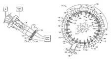
- FIG. 1is schematic representation of a combustion engine in which the secondary fuel delivery system of the present invention may be used;
- FIG. 2is a side, partial cutaway view of a combustor employing the secondary fuel delivery system of the present invention
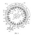
- FIG. 3is a cross-section view of the manifold of the present invention taken along cutting line 3 - 3 in FIG. 2 ;
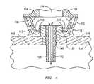
- FIG. 4is a cross-section view of the manifold of the present invention taken along cutting line 4 - 4 in FIG. 3
- the fuel delivery system 110is especially-suited for providing a secondary stream 112 of fuel and/or diluent to a secondary combustion zone 114 , located within the transition piece 116 , downstream of the primary combustion zone 48 , as a way of, among other things, reducing NOx emissions levels during operation of the associated turbine engine, not shown.
- a secondary combustion zone 114located within the transition piece 116 , downstream of the primary combustion zone 48 , as a way of, among other things, reducing NOx emissions levels during operation of the associated turbine engine, not shown.
- the secondary fuel delivery system 110includes a manifold 122 disposed circumferentially around the transition piece 116 , a manifold inlet port 134 through which a secondary supply of fuel 128 and/or diluent 130 enters the manifold main cavity 136 , and a plurality of long and short injector nozzles 124 , 126 for distributing fuel and/or diluent into a secondary combustion zone 114 located in the interior region 132 of the transition piece 116 .
- a strategically-positioned flowsleeve 146ensures fuel/diluent flow velocity in the manifold 122 at key locations away from the inlet 134 is maintained at levels effective to provide adequate transition piece cooling.
- the manifold 122is formed integral to the boundary wall 123 of the transition piece 116 .
- the transition of the present inventionis easy to manufacture and is resistant to modal excitation generated by combustor acoustics and mechanical vibration. It is noted, however, that the manifold 122 and transition piece 116 need not be integral to provide vibration attenuation—arrangements in which the manifold radially-inward boundary 138 is a discrete element would also suffice, as long as the manifold 122 and transition piece 116 have contact sufficient to generate substantially the same the level of stiffness in the manifold as is found in the portion of the transition piece surrounding the secondary combustion region 114 .
- the radially-inward wall or boundary 138 of the manifold 122is characterized by a series of mounting holes 140 through which the injector nozzles 124 , 26 are inserted.
- the injector nozzles 124 , 126may be spaced apart from one another as desired. In one embodiment, the secondary injectors are spaced apart equidistant from one another.
- the radially-outward boundary or cover 142 of the manifold 122includes access ports 144 which, when removed, provide access to the nozzles 124 , 126 as needed.
- the nozzles 124 , 126 and mounting holes 140also include matching threads to allow for screw-in type mounting of the nozzles.
- the nozzlesmay be replaced or moved as needed to accommodate a variety of circumferentially-varied flow profiles or engine operating conditions.
- Other mounting methods, such as welding or brazingwould also suffice in applications where easily-removable mounting is not needed or desired.
- the access ports 144are formed into groups that help reduce thermal stress induced by differential thermal expansion between the inner and outer regions of manifold 138 , 142 .
- the temperature difference between the region inside 132 the transition piece and outside 148 the transition piecemay be significant during operation and may cause a significant thermal stress to the body of manifold 22 .
- the temperature within secondary combustion zone 114 of transition piece 116may be in the range of between about 1500° F. and about 1800° F. while the temperature outside of transition piece 116 may be between about 700° F. and 900° F., and typically about 800° F.
- the portsare arranged in groups of three, with the groups being spaced apart by heat dissipation gaps 150 .
- the inclusion of these heat dissipation gaps 150helps the secondary fuel delivery system 110 tolerate extended periods of cyclic thermal loading during operation.
- the heat dissipation gaps 150may be formed in several ways, for example, the manifold outer cover 142 may include a plurality of segments 152 , with each segment 152 adapted for placement over a plurality of injectors, and wherein a gap 150 is defined between each adjacent segment 152 of the manifold cover 142 .
- the gaps 150may also be directly machined into the manifold 122 when the manifold is formed.
- the injectors 124 , 126 and manifold 122may be made from Hastelloy-X, a nickel-chromium-iron-molybdenum alloy, or any other suitable high temperature material or metallic alloy. It is noted that the access ports 144 need not be arranged in groups of three, and the heat dissipation gaps 150 need not be uniformly distributed about the manifold, and may be left out altogether depending on the cooling requirements of a particular engine design.
- the manifold inlet port 134is configured to receive a stream 112 of secondary fuel 128 and/or diluent 130 and to provide the stream to the injectors 124 , 126 .
- the secondary fuel 112may be delivered by a line stemming from any suitable source, not shown, which may be the same as, or independent from, the primary fuel source, not shown.
- the diluent 130may be a variety of materials, including air, steam, or an inert gas, such as nitrogen, for the reasons set forth below.
- the secondary fuel 128 and any additional material 130may be premixed before entry into inlet 134 by passing the streams through a mixer or swirling vane, not shown, or may be introduced independently and mixed within manifold 122 .
- a flow-accelerating flowsleeve 146is strategically located within the manifold 122 , at a region 156 , located generally opposite the manifold inlet port 134 , to ensure that flow velocity is maintained at a level effective to provide transition cooling.
- the flowsleeve 146preferably resembles a circumferentially-arcuate trough having opposite side panels 158 spaced apart by a blocking band 160 oriented generally-parallel to the radially-inward wall 138 of the manifold 122 .
- the stream of fuel and/or diluentflows between the manifold radially-inward boundary 138 and the blocking band 160 .
- the injector nozzles 124 , 126extend through passthrough apertures 166 located in the flowsleeve blocking band 160 , and the pass-through apertures 166 are sized to allow the secondary fuel/diluent stream 112 to flow radially outward, away from the manifold radially-inward boundary 138 and the blocking band 160 , along the nozzle 124 , 126 exteriors and then change direction to enter and flow through the nozzles, before exiting the manifold and travelling into the secondary combustion zone 114 .
- the consequent increase in convection heat transfer in the area occupied by the flow sleeve 146reduces the thermal gradients in this region, thereby reducing thermo-mechanical stresses.
- the increase in velocity of the fluids moving through the region occupied by the flowsleeve 146improves the heat transfer characteristics of the region and ensures adequate cooling. Without the flowsleeve 146 the portion of manifold 122 opposite the manifold inlet would likely experience thermo-mechanical stresses because the fuel-diluent mass flow is at a minimum in this region 156 , it is also likely that without sufficient cooling, the material limits of the components would be reached or exceeded and failure could occur.
- the region 156 occupied by the flowsleeveis centered approximately 180 degrees circumferentially-away from the manifold inlet port 134 , extending along an arc about 120 degrees in length, but could be as narrow as about 10 degrees.
- the flared, or trough-like, flowsleeve shape described aboveprovides increased flowsleeve volume, while maintaining a relatively-low manifold profile, thereby increasing the flow-accelerating efficiency of the manifold.
- Other arrangements, such as contoured or radially-aligned flowsleeve side panels 158could also be used, depending on the degree of flow blockage desired along the circumferential span of the manifold.
- the flowsleeve 146is shown as circumferentially arcuate, but may be of any shape that allows the flowsleeve to fit within the manifold and which provides a volume sufficient to accelerate the secondary stream 112 of fuel and/or diluent as desired.
- the volume occupied by the flowsleeve 146need not be uniform, but generally increases as a function of flow distance away from the inlet port 134 to compensate for flow velocity loss tendencies that increase in relation to this distance.
- the volume occupied by the flowsleeve 146is proportional to the amount of flow rate increase desired in order to provide adequate cooling in regions where non-accelerated flow does not naturally provide sufficient cooling.
- the flow sleeve 182may be installed in a variety of circumferential positions within manifold 152 , and the desired location of the flowsleeve may vary from application to application, but a flow sleeve 146 is appropriate when flow velocity in a region is less than about 60% of the nominal flow velocity (Vn) found immediately proximate the manifold inlet port 134 , and the optimal dimensions of the flow sleeve side panels 158 , blocking band 160 , and pass-through apertures 166 is such that the resultant flow volume in the region occupied by the flowsleeve 146 is approximately 65% to 120% the nominal flow velocity Vn found in the vicinity of the inlet port.
- Vnnominal flow velocity
- Accelerating to above the nominal velocity Vnis useful in applications of particularly-long flow distance, where temperature gradients between the transition interior are higher than average, or other settings in which the secondary fuel/diluent stream 112 exhibits a reduced ability to dissipate heat; as highly-accelerated flow in these regions can further increase flow turbulence and provide an increase in cooling.
- the transition piece 116may have a plurality of effusion cooling holes 168 disposed therein for allowing air to flow about and into the secondary combustion zone 114 , thereby cooling the body of the transition piece.
- Diffusion holes 168may be disposed at an angle from about 5 to about 45 degrees, and in one embodiment about 10 degrees, or may be any other suitable angle for enabling the cooling of the transition body.
Landscapes
- Engineering & Computer Science (AREA)
- Chemical & Material Sciences (AREA)
- Combustion & Propulsion (AREA)
- Mechanical Engineering (AREA)
- General Engineering & Computer Science (AREA)
- Fuel-Injection Apparatus (AREA)
Abstract
Description
Claims (10)
Priority Applications (1)
| Application Number | Priority Date | Filing Date | Title |
|---|---|---|---|
| US12/210,356US7665309B2 (en) | 2007-09-14 | 2008-09-15 | Secondary fuel delivery system |
Applications Claiming Priority (4)
| Application Number | Priority Date | Filing Date | Title |
|---|---|---|---|
| US97240507P | 2007-09-14 | 2007-09-14 | |
| US97239507P | 2007-09-14 | 2007-09-14 | |
| US12/194,611US8387398B2 (en) | 2007-09-14 | 2008-08-20 | Apparatus and method for controlling the secondary injection of fuel |
| US12/210,356US7665309B2 (en) | 2007-09-14 | 2008-09-15 | Secondary fuel delivery system |
Related Parent Applications (1)
| Application Number | Title | Priority Date | Filing Date |
|---|---|---|---|
| US12/194,611Continuation-In-PartUS8387398B2 (en) | 2007-09-14 | 2008-08-20 | Apparatus and method for controlling the secondary injection of fuel |
Publications (2)
| Publication Number | Publication Date |
|---|---|
| US20090071159A1 US20090071159A1 (en) | 2009-03-19 |
| US7665309B2true US7665309B2 (en) | 2010-02-23 |
Family
ID=40453034
Family Applications (1)
| Application Number | Title | Priority Date | Filing Date |
|---|---|---|---|
| US12/210,356ActiveUS7665309B2 (en) | 2007-09-14 | 2008-09-15 | Secondary fuel delivery system |
Country Status (1)
| Country | Link |
|---|---|
| US (1) | US7665309B2 (en) |
Cited By (49)
| Publication number | Priority date | Publication date | Assignee | Title |
|---|---|---|---|---|
| US20100064692A1 (en)* | 2007-03-15 | 2010-03-18 | Kam-Kei Lam | Burner fuel staging |
| US20100115953A1 (en)* | 2008-11-12 | 2010-05-13 | Davis Jr Lewis Berkley | Integrated Combustor and Stage 1 Nozzle in a Gas Turbine and Method |
| US20110162375A1 (en)* | 2010-01-05 | 2011-07-07 | General Electric Company | Secondary Combustion Fuel Supply Systems |
| US8429915B1 (en)* | 2011-10-17 | 2013-04-30 | General Electric Company | Injector having multiple fuel pegs |
| US20130104553A1 (en)* | 2011-11-01 | 2013-05-02 | General Electric Company | Injection apparatus |
| CN103090417A (en)* | 2011-11-07 | 2013-05-08 | 通用电气公司 | Transition piece aft frame |
| US8479518B1 (en) | 2012-07-11 | 2013-07-09 | General Electric Company | System for supplying a working fluid to a combustor |
| US20130283804A1 (en)* | 2012-04-30 | 2013-10-31 | General Electric Company | Transition duct with late injection in turbine system |
| US8677753B2 (en) | 2012-05-08 | 2014-03-25 | General Electric Company | System for supplying a working fluid to a combustor |
| US20140238034A1 (en)* | 2011-11-17 | 2014-08-28 | General Electric Company | Turbomachine combustor assembly and method of operating a turbomachine |
| US9052115B2 (en) | 2012-04-25 | 2015-06-09 | General Electric Company | System and method for supplying a working fluid to a combustor |
| US20150159877A1 (en)* | 2013-12-06 | 2015-06-11 | General Electric Company | Late lean injection manifold mixing system |
| US20150176495A1 (en)* | 2013-12-20 | 2015-06-25 | Pratt & Whitney Canada Crop. | Fluid manifold for gas turbine engine and method for delivering fuel to a combustor using same |
| US9097424B2 (en) | 2012-03-12 | 2015-08-04 | General Electric Company | System for supplying a fuel and working fluid mixture to a combustor |
| US9151500B2 (en) | 2012-03-15 | 2015-10-06 | General Electric Company | System for supplying a fuel and a working fluid through a liner to a combustion chamber |
| US9170024B2 (en) | 2012-01-06 | 2015-10-27 | General Electric Company | System and method for supplying a working fluid to a combustor |
| US9188337B2 (en) | 2012-01-13 | 2015-11-17 | General Electric Company | System and method for supplying a working fluid to a combustor via a non-uniform distribution manifold |
| US9228499B2 (en) | 2011-08-11 | 2016-01-05 | General Electric Company | System for secondary fuel injection in a gas turbine engine |
| US9284888B2 (en) | 2012-04-25 | 2016-03-15 | General Electric Company | System for supplying fuel to late-lean fuel injectors of a combustor |
| US20160178200A1 (en)* | 2014-12-22 | 2016-06-23 | General Electric Technology Gmbh | Separate feedings of cooling and dilution air |
| US9388987B2 (en) | 2011-09-22 | 2016-07-12 | General Electric Company | Combustor and method for supplying fuel to a combustor |
| US20160245523A1 (en)* | 2015-02-20 | 2016-08-25 | United Technologies Corporation | Angled main mixer for axially controlled stoichiometry combustor |
| US9429325B2 (en) | 2011-06-30 | 2016-08-30 | General Electric Company | Combustor and method of supplying fuel to the combustor |
| US9528705B2 (en) | 2014-04-08 | 2016-12-27 | General Electric Company | Trapped vortex fuel injector and method for manufacture |
| US9551490B2 (en) | 2014-04-08 | 2017-01-24 | General Electric Company | System for cooling a fuel injector extending into a combustion gas flow field and method for manufacture |
| US9593851B2 (en) | 2011-06-30 | 2017-03-14 | General Electric Company | Combustor and method of supplying fuel to the combustor |
| US20170227225A1 (en)* | 2016-02-09 | 2017-08-10 | General Electric Company | Fuel injectors and methods of fabricating same |
| US20180202662A1 (en)* | 2015-07-07 | 2018-07-19 | Hanwha Techwin Co., Ltd. | Combustor |
| US10520194B2 (en) | 2016-03-25 | 2019-12-31 | General Electric Company | Radially stacked fuel injection module for a segmented annular combustion system |
| US10533750B2 (en) | 2014-09-05 | 2020-01-14 | Siemens Aktiengesellschaft | Cross ignition flame duct |
| US10563869B2 (en) | 2016-03-25 | 2020-02-18 | General Electric Company | Operation and turndown of a segmented annular combustion system |
| US10584880B2 (en) | 2016-03-25 | 2020-03-10 | General Electric Company | Mounting of integrated combustor nozzles in a segmented annular combustion system |
| US10584638B2 (en) | 2016-03-25 | 2020-03-10 | General Electric Company | Turbine nozzle cooling with panel fuel injector |
| US10584876B2 (en) | 2016-03-25 | 2020-03-10 | General Electric Company | Micro-channel cooling of integrated combustor nozzle of a segmented annular combustion system |
| US10605459B2 (en) | 2016-03-25 | 2020-03-31 | General Electric Company | Integrated combustor nozzle for a segmented annular combustion system |
| US10641491B2 (en) | 2016-03-25 | 2020-05-05 | General Electric Company | Cooling of integrated combustor nozzle of segmented annular combustion system |
| US10690350B2 (en) | 2016-11-28 | 2020-06-23 | General Electric Company | Combustor with axially staged fuel injection |
| US10718523B2 (en) | 2017-05-12 | 2020-07-21 | General Electric Company | Fuel injectors with multiple outlet slots for use in gas turbine combustor |
| US10830442B2 (en) | 2016-03-25 | 2020-11-10 | General Electric Company | Segmented annular combustion system with dual fuel capability |
| US11156362B2 (en) | 2016-11-28 | 2021-10-26 | General Electric Company | Combustor with axially staged fuel injection |
| US11255545B1 (en) | 2020-10-26 | 2022-02-22 | General Electric Company | Integrated combustion nozzle having a unified head end |
| US11371702B2 (en) | 2020-08-31 | 2022-06-28 | General Electric Company | Impingement panel for a turbomachine |
| US11371709B2 (en) | 2020-06-30 | 2022-06-28 | General Electric Company | Combustor air flow path |
| US11428413B2 (en) | 2016-03-25 | 2022-08-30 | General Electric Company | Fuel injection module for segmented annular combustion system |
| US11460191B2 (en) | 2020-08-31 | 2022-10-04 | General Electric Company | Cooling insert for a turbomachine |
| US11614233B2 (en) | 2020-08-31 | 2023-03-28 | General Electric Company | Impingement panel support structure and method of manufacture |
| US11767766B1 (en) | 2022-07-29 | 2023-09-26 | General Electric Company | Turbomachine airfoil having impingement cooling passages |
| US11994292B2 (en) | 2020-08-31 | 2024-05-28 | General Electric Company | Impingement cooling apparatus for turbomachine |
| US11994293B2 (en) | 2020-08-31 | 2024-05-28 | General Electric Company | Impingement cooling apparatus support structure and method of manufacture |
Families Citing this family (15)
| Publication number | Priority date | Publication date | Assignee | Title |
|---|---|---|---|---|
| US8281594B2 (en)* | 2009-09-08 | 2012-10-09 | Siemens Energy, Inc. | Fuel injector for use in a gas turbine engine |
| US8991192B2 (en)* | 2009-09-24 | 2015-03-31 | Siemens Energy, Inc. | Fuel nozzle assembly for use as structural support for a duct structure in a combustor of a gas turbine engine |
| US8082739B2 (en)* | 2010-04-12 | 2011-12-27 | General Electric Company | Combustor exit temperature profile control via fuel staging and related method |
| US9297534B2 (en) | 2011-07-29 | 2016-03-29 | General Electric Company | Combustor portion for a turbomachine and method of operating a turbomachine |
| US9182122B2 (en)* | 2011-10-05 | 2015-11-10 | General Electric Company | Combustor and method for supplying flow to a combustor |
| US9243507B2 (en)* | 2012-01-09 | 2016-01-26 | General Electric Company | Late lean injection system transition piece |
| US8683805B2 (en)* | 2012-08-06 | 2014-04-01 | General Electric Company | Injector seal for a gas turbomachine |
| US9423131B2 (en)* | 2012-10-10 | 2016-08-23 | General Electric Company | Air management arrangement for a late lean injection combustor system and method of routing an airflow |
| US9383104B2 (en)* | 2013-03-18 | 2016-07-05 | General Electric Company | Continuous combustion liner for a combustor of a gas turbine |
| US20150167980A1 (en)* | 2013-12-18 | 2015-06-18 | Jared M. Pent | Axial stage injection dual frequency resonator for a combustor of a gas turbine engine |
| US10480792B2 (en)* | 2015-03-06 | 2019-11-19 | General Electric Company | Fuel staging in a gas turbine engine |
| US11156164B2 (en) | 2019-05-21 | 2021-10-26 | General Electric Company | System and method for high frequency accoustic dampers with caps |
| US11174792B2 (en) | 2019-05-21 | 2021-11-16 | General Electric Company | System and method for high frequency acoustic dampers with baffles |
| CN110489863B (en)* | 2019-08-20 | 2023-05-26 | 成立航空技术(成都)有限公司 | Method for determining temperature field index of main combustion chamber outlet of aero-engine |
| CN114719291B (en)* | 2022-06-08 | 2022-08-26 | 中国航发四川燃气涡轮研究院 | Engine outlet temperature field control method |
Citations (35)
| Publication number | Priority date | Publication date | Assignee | Title |
|---|---|---|---|---|
| US3055179A (en) | 1958-03-05 | 1962-09-25 | Rolls Royce | Gas turbine engine combustion equipment including multiple air inlets and fuel injection means |
| US3099134A (en) | 1959-12-24 | 1963-07-30 | Havilland Engine Co Ltd | Combustion chambers |
| US3872664A (en) | 1973-10-15 | 1975-03-25 | United Aircraft Corp | Swirl combustor with vortex burning and mixing |
| US3934409A (en) | 1973-03-13 | 1976-01-27 | Societe Nationale D'etude Et De Construction De Moteurs D'aviation | Gas turbine combustion chambers |
| US4028888A (en) | 1974-05-03 | 1977-06-14 | Norwalk-Turbo Inc. | Fuel distribution manifold to an annular combustion chamber |
| US4192139A (en) | 1976-07-02 | 1980-03-11 | Volkswagenwerk Aktiengesellschaft | Combustion chamber for gas turbines |
| US4265615A (en) | 1978-12-11 | 1981-05-05 | United Technologies Corporation | Fuel injection system for low emission burners |
| US4420929A (en) | 1979-01-12 | 1983-12-20 | General Electric Company | Dual stage-dual mode low emission gas turbine combustion system |
| US4590769A (en) | 1981-01-12 | 1986-05-27 | United Technologies Corporation | High-performance burner construction |
| US4928481A (en)* | 1988-07-13 | 1990-05-29 | Prutech Ii | Staged low NOx premix gas turbine combustor |
| US5274991A (en)* | 1992-03-30 | 1994-01-04 | General Electric Company | Dry low NOx multi-nozzle combustion liner cap assembly |
| US5394688A (en) | 1993-10-27 | 1995-03-07 | Westinghouse Electric Corporation | Gas turbine combustor swirl vane arrangement |
| US5408825A (en) | 1993-12-03 | 1995-04-25 | Westinghouse Electric Corporation | Dual fuel gas turbine combustor |
| US5623819A (en) | 1994-06-07 | 1997-04-29 | Westinghouse Electric Corporation | Method and apparatus for sequentially staged combustion using a catalyst |
| US5640851A (en) | 1993-05-24 | 1997-06-24 | Rolls-Royce Plc | Gas turbine engine combustion chamber |
| US5647215A (en) | 1995-11-07 | 1997-07-15 | Westinghouse Electric Corporation | Gas turbine combustor with turbulence enhanced mixing fuel injectors |
| US5657632A (en) | 1994-11-10 | 1997-08-19 | Westinghouse Electric Corporation | Dual fuel gas turbine combustor |
| US5687571A (en) | 1995-02-20 | 1997-11-18 | Asea Brown Boveri Ag | Combustion chamber with two-stage combustion |
| US5749219A (en) | 1989-11-30 | 1998-05-12 | United Technologies Corporation | Combustor with first and second zones |
| US5802854A (en) | 1994-02-24 | 1998-09-08 | Kabushiki Kaisha Toshiba | Gas turbine multi-stage combustion system |
| US5826429A (en) | 1995-12-22 | 1998-10-27 | General Electric Co. | Catalytic combustor with lean direct injection of gas fuel for low emissions combustion and methods of operation |
| US6047550A (en) | 1996-05-02 | 2000-04-11 | General Electric Co. | Premixing dry low NOx emissions combustor with lean direct injection of gas fuel |
| US6092363A (en) | 1998-06-19 | 2000-07-25 | Siemens Westinghouse Power Corporation | Low Nox combustor having dual fuel injection system |
| US20010049932A1 (en) | 1996-05-02 | 2001-12-13 | Beebe Kenneth W. | Premixing dry low NOx emissions combustor with lean direct injection of gas fuel |
| US6343462B1 (en)* | 1998-11-13 | 2002-02-05 | Praxair Technology, Inc. | Gas turbine power augmentation by the addition of nitrogen and moisture to the fuel gas |
| US20030010035A1 (en)* | 2001-07-13 | 2003-01-16 | Gilbert Farmer | Method for thermal barrier coating and a liner made using said method |
| US6513334B2 (en) | 2000-08-10 | 2003-02-04 | Rolls-Royce Plc | Combustion chamber |
| US20030024234A1 (en) | 2001-08-02 | 2003-02-06 | Siemens Westinghouse Power Corporation | Secondary combustor for low NOx gas combustion turbine |
| US6868676B1 (en) | 2002-12-20 | 2005-03-22 | General Electric Company | Turbine containing system and an injector therefor |
| US7082770B2 (en) | 2003-12-24 | 2006-08-01 | Martling Vincent C | Flow sleeve for a low NOx combustor |
| US7198483B2 (en) | 2001-01-30 | 2007-04-03 | Alstom Technology Ltd. | Burner unit and method for operation thereof |
| US20070234733A1 (en) | 2005-09-12 | 2007-10-11 | Harris Mark M | Small gas turbine engine with multiple burn zones |
| US7303388B2 (en) | 2004-07-01 | 2007-12-04 | Air Products And Chemicals, Inc. | Staged combustion system with ignition-assisted fuel lances |
| US7302801B2 (en) | 2004-04-19 | 2007-12-04 | Hamilton Sundstrand Corporation | Lean-staged pyrospin combustor |
| US20080072599A1 (en)* | 2006-09-26 | 2008-03-27 | Oleg Morenko | Heat shield for a fuel manifold |
- 2008
- 2008-09-15USUS12/210,356patent/US7665309B2/enactiveActive
Patent Citations (39)
| Publication number | Priority date | Publication date | Assignee | Title |
|---|---|---|---|---|
| US3055179A (en) | 1958-03-05 | 1962-09-25 | Rolls Royce | Gas turbine engine combustion equipment including multiple air inlets and fuel injection means |
| US3099134A (en) | 1959-12-24 | 1963-07-30 | Havilland Engine Co Ltd | Combustion chambers |
| US3934409A (en) | 1973-03-13 | 1976-01-27 | Societe Nationale D'etude Et De Construction De Moteurs D'aviation | Gas turbine combustion chambers |
| US3872664A (en) | 1973-10-15 | 1975-03-25 | United Aircraft Corp | Swirl combustor with vortex burning and mixing |
| US4028888A (en) | 1974-05-03 | 1977-06-14 | Norwalk-Turbo Inc. | Fuel distribution manifold to an annular combustion chamber |
| US4192139A (en) | 1976-07-02 | 1980-03-11 | Volkswagenwerk Aktiengesellschaft | Combustion chamber for gas turbines |
| US4265615A (en) | 1978-12-11 | 1981-05-05 | United Technologies Corporation | Fuel injection system for low emission burners |
| US4420929A (en) | 1979-01-12 | 1983-12-20 | General Electric Company | Dual stage-dual mode low emission gas turbine combustion system |
| US4590769A (en) | 1981-01-12 | 1986-05-27 | United Technologies Corporation | High-performance burner construction |
| US4928481A (en)* | 1988-07-13 | 1990-05-29 | Prutech Ii | Staged low NOx premix gas turbine combustor |
| US5749219A (en) | 1989-11-30 | 1998-05-12 | United Technologies Corporation | Combustor with first and second zones |
| US5274991A (en)* | 1992-03-30 | 1994-01-04 | General Electric Company | Dry low NOx multi-nozzle combustion liner cap assembly |
| US5640851A (en) | 1993-05-24 | 1997-06-24 | Rolls-Royce Plc | Gas turbine engine combustion chamber |
| US5479782A (en) | 1993-10-27 | 1996-01-02 | Westinghouse Electric Corporation | Gas turbine combustor |
| US5394688A (en) | 1993-10-27 | 1995-03-07 | Westinghouse Electric Corporation | Gas turbine combustor swirl vane arrangement |
| US5408825A (en) | 1993-12-03 | 1995-04-25 | Westinghouse Electric Corporation | Dual fuel gas turbine combustor |
| US6418725B1 (en) | 1994-02-24 | 2002-07-16 | Kabushiki Kaisha Toshiba | Gas turbine staged control method |
| US5802854A (en) | 1994-02-24 | 1998-09-08 | Kabushiki Kaisha Toshiba | Gas turbine multi-stage combustion system |
| US5623819A (en) | 1994-06-07 | 1997-04-29 | Westinghouse Electric Corporation | Method and apparatus for sequentially staged combustion using a catalyst |
| US5657632A (en) | 1994-11-10 | 1997-08-19 | Westinghouse Electric Corporation | Dual fuel gas turbine combustor |
| US5687571A (en) | 1995-02-20 | 1997-11-18 | Asea Brown Boveri Ag | Combustion chamber with two-stage combustion |
| US5647215A (en) | 1995-11-07 | 1997-07-15 | Westinghouse Electric Corporation | Gas turbine combustor with turbulence enhanced mixing fuel injectors |
| US5850731A (en) | 1995-12-22 | 1998-12-22 | General Electric Co. | Catalytic combustor with lean direct injection of gas fuel for low emissions combustion and methods of operation |
| US5826429A (en) | 1995-12-22 | 1998-10-27 | General Electric Co. | Catalytic combustor with lean direct injection of gas fuel for low emissions combustion and methods of operation |
| US6047550A (en) | 1996-05-02 | 2000-04-11 | General Electric Co. | Premixing dry low NOx emissions combustor with lean direct injection of gas fuel |
| US6192688B1 (en) | 1996-05-02 | 2001-02-27 | General Electric Co. | Premixing dry low nox emissions combustor with lean direct injection of gas fule |
| US20010049932A1 (en) | 1996-05-02 | 2001-12-13 | Beebe Kenneth W. | Premixing dry low NOx emissions combustor with lean direct injection of gas fuel |
| US6092363A (en) | 1998-06-19 | 2000-07-25 | Siemens Westinghouse Power Corporation | Low Nox combustor having dual fuel injection system |
| US6343462B1 (en)* | 1998-11-13 | 2002-02-05 | Praxair Technology, Inc. | Gas turbine power augmentation by the addition of nitrogen and moisture to the fuel gas |
| US6513334B2 (en) | 2000-08-10 | 2003-02-04 | Rolls-Royce Plc | Combustion chamber |
| US7198483B2 (en) | 2001-01-30 | 2007-04-03 | Alstom Technology Ltd. | Burner unit and method for operation thereof |
| US20030010035A1 (en)* | 2001-07-13 | 2003-01-16 | Gilbert Farmer | Method for thermal barrier coating and a liner made using said method |
| US20030024234A1 (en) | 2001-08-02 | 2003-02-06 | Siemens Westinghouse Power Corporation | Secondary combustor for low NOx gas combustion turbine |
| US6868676B1 (en) | 2002-12-20 | 2005-03-22 | General Electric Company | Turbine containing system and an injector therefor |
| US7082770B2 (en) | 2003-12-24 | 2006-08-01 | Martling Vincent C | Flow sleeve for a low NOx combustor |
| US7302801B2 (en) | 2004-04-19 | 2007-12-04 | Hamilton Sundstrand Corporation | Lean-staged pyrospin combustor |
| US7303388B2 (en) | 2004-07-01 | 2007-12-04 | Air Products And Chemicals, Inc. | Staged combustion system with ignition-assisted fuel lances |
| US20070234733A1 (en) | 2005-09-12 | 2007-10-11 | Harris Mark M | Small gas turbine engine with multiple burn zones |
| US20080072599A1 (en)* | 2006-09-26 | 2008-03-27 | Oleg Morenko | Heat shield for a fuel manifold |
Cited By (67)
| Publication number | Priority date | Publication date | Assignee | Title |
|---|---|---|---|---|
| US20100064692A1 (en)* | 2007-03-15 | 2010-03-18 | Kam-Kei Lam | Burner fuel staging |
| US8484979B2 (en)* | 2007-03-15 | 2013-07-16 | Siemens Aktiengesellschaft | Burner fuel staging |
| US9822649B2 (en)* | 2008-11-12 | 2017-11-21 | General Electric Company | Integrated combustor and stage 1 nozzle in a gas turbine and method |
| US20100115953A1 (en)* | 2008-11-12 | 2010-05-13 | Davis Jr Lewis Berkley | Integrated Combustor and Stage 1 Nozzle in a Gas Turbine and Method |
| US20110162375A1 (en)* | 2010-01-05 | 2011-07-07 | General Electric Company | Secondary Combustion Fuel Supply Systems |
| US9429325B2 (en) | 2011-06-30 | 2016-08-30 | General Electric Company | Combustor and method of supplying fuel to the combustor |
| US9593851B2 (en) | 2011-06-30 | 2017-03-14 | General Electric Company | Combustor and method of supplying fuel to the combustor |
| US9228499B2 (en) | 2011-08-11 | 2016-01-05 | General Electric Company | System for secondary fuel injection in a gas turbine engine |
| US9388987B2 (en) | 2011-09-22 | 2016-07-12 | General Electric Company | Combustor and method for supplying fuel to a combustor |
| US8429915B1 (en)* | 2011-10-17 | 2013-04-30 | General Electric Company | Injector having multiple fuel pegs |
| US20130104553A1 (en)* | 2011-11-01 | 2013-05-02 | General Electric Company | Injection apparatus |
| US20130111910A1 (en)* | 2011-11-07 | 2013-05-09 | General Electric Company | Transition piece aft frame |
| CN103090417A (en)* | 2011-11-07 | 2013-05-08 | 通用电气公司 | Transition piece aft frame |
| CN103090417B (en)* | 2011-11-07 | 2016-10-05 | 通用电气公司 | Transition Piece Aft Frame |
| US9127552B2 (en)* | 2011-11-07 | 2015-09-08 | General Electric Company | Transition piece aft frame with fuel injection apertures |
| US20140238034A1 (en)* | 2011-11-17 | 2014-08-28 | General Electric Company | Turbomachine combustor assembly and method of operating a turbomachine |
| US9170024B2 (en) | 2012-01-06 | 2015-10-27 | General Electric Company | System and method for supplying a working fluid to a combustor |
| US9188337B2 (en) | 2012-01-13 | 2015-11-17 | General Electric Company | System and method for supplying a working fluid to a combustor via a non-uniform distribution manifold |
| US9097424B2 (en) | 2012-03-12 | 2015-08-04 | General Electric Company | System for supplying a fuel and working fluid mixture to a combustor |
| US9151500B2 (en) | 2012-03-15 | 2015-10-06 | General Electric Company | System for supplying a fuel and a working fluid through a liner to a combustion chamber |
| US9284888B2 (en) | 2012-04-25 | 2016-03-15 | General Electric Company | System for supplying fuel to late-lean fuel injectors of a combustor |
| US9052115B2 (en) | 2012-04-25 | 2015-06-09 | General Electric Company | System and method for supplying a working fluid to a combustor |
| US20130283804A1 (en)* | 2012-04-30 | 2013-10-31 | General Electric Company | Transition duct with late injection in turbine system |
| US9133722B2 (en)* | 2012-04-30 | 2015-09-15 | General Electric Company | Transition duct with late injection in turbine system |
| US8677753B2 (en) | 2012-05-08 | 2014-03-25 | General Electric Company | System for supplying a working fluid to a combustor |
| US8863523B2 (en) | 2012-07-11 | 2014-10-21 | General Electric Company | System for supplying a working fluid to a combustor |
| US8479518B1 (en) | 2012-07-11 | 2013-07-09 | General Electric Company | System for supplying a working fluid to a combustor |
| US20150159877A1 (en)* | 2013-12-06 | 2015-06-11 | General Electric Company | Late lean injection manifold mixing system |
| US20150176495A1 (en)* | 2013-12-20 | 2015-06-25 | Pratt & Whitney Canada Crop. | Fluid manifold for gas turbine engine and method for delivering fuel to a combustor using same |
| US10760495B2 (en) | 2013-12-20 | 2020-09-01 | Pratt & Whitney Canada Corp. | Fluid manifold for gas turbine engine and method for delivering fuel to a combustor using same |
| US9995220B2 (en)* | 2013-12-20 | 2018-06-12 | Pratt & Whitney Canada Corp. | Fluid manifold for gas turbine engine and method for delivering fuel to a combustor using same |
| US9528705B2 (en) | 2014-04-08 | 2016-12-27 | General Electric Company | Trapped vortex fuel injector and method for manufacture |
| US9551490B2 (en) | 2014-04-08 | 2017-01-24 | General Electric Company | System for cooling a fuel injector extending into a combustion gas flow field and method for manufacture |
| US10533750B2 (en) | 2014-09-05 | 2020-01-14 | Siemens Aktiengesellschaft | Cross ignition flame duct |
| US10443849B2 (en)* | 2014-12-22 | 2019-10-15 | Ansaldo Energia Switzerland AG | Separate feedings of cooling and dilution air |
| US20160178200A1 (en)* | 2014-12-22 | 2016-06-23 | General Electric Technology Gmbh | Separate feedings of cooling and dilution air |
| US20160245523A1 (en)* | 2015-02-20 | 2016-08-25 | United Technologies Corporation | Angled main mixer for axially controlled stoichiometry combustor |
| US10060629B2 (en)* | 2015-02-20 | 2018-08-28 | United Technologies Corporation | Angled radial fuel/air delivery system for combustor |
| US20180202662A1 (en)* | 2015-07-07 | 2018-07-19 | Hanwha Techwin Co., Ltd. | Combustor |
| US10648673B2 (en)* | 2015-07-07 | 2020-05-12 | Hanwha Aerospace Co., Ltd. | Combustor |
| US20170227225A1 (en)* | 2016-02-09 | 2017-08-10 | General Electric Company | Fuel injectors and methods of fabricating same |
| US10584876B2 (en) | 2016-03-25 | 2020-03-10 | General Electric Company | Micro-channel cooling of integrated combustor nozzle of a segmented annular combustion system |
| US10520194B2 (en) | 2016-03-25 | 2019-12-31 | General Electric Company | Radially stacked fuel injection module for a segmented annular combustion system |
| US10584880B2 (en) | 2016-03-25 | 2020-03-10 | General Electric Company | Mounting of integrated combustor nozzles in a segmented annular combustion system |
| US10605459B2 (en) | 2016-03-25 | 2020-03-31 | General Electric Company | Integrated combustor nozzle for a segmented annular combustion system |
| US10641175B2 (en) | 2016-03-25 | 2020-05-05 | General Electric Company | Panel fuel injector |
| US10641176B2 (en) | 2016-03-25 | 2020-05-05 | General Electric Company | Combustion system with panel fuel injector |
| US10641491B2 (en) | 2016-03-25 | 2020-05-05 | General Electric Company | Cooling of integrated combustor nozzle of segmented annular combustion system |
| US10563869B2 (en) | 2016-03-25 | 2020-02-18 | General Electric Company | Operation and turndown of a segmented annular combustion system |
| US10655541B2 (en) | 2016-03-25 | 2020-05-19 | General Electric Company | Segmented annular combustion system |
| US10690056B2 (en) | 2016-03-25 | 2020-06-23 | General Electric Company | Segmented annular combustion system with axial fuel staging |
| US11428413B2 (en) | 2016-03-25 | 2022-08-30 | General Electric Company | Fuel injection module for segmented annular combustion system |
| US11002190B2 (en) | 2016-03-25 | 2021-05-11 | General Electric Company | Segmented annular combustion system |
| US10724441B2 (en) | 2016-03-25 | 2020-07-28 | General Electric Company | Segmented annular combustion system |
| US10584638B2 (en) | 2016-03-25 | 2020-03-10 | General Electric Company | Turbine nozzle cooling with panel fuel injector |
| US10830442B2 (en) | 2016-03-25 | 2020-11-10 | General Electric Company | Segmented annular combustion system with dual fuel capability |
| US11156362B2 (en) | 2016-11-28 | 2021-10-26 | General Electric Company | Combustor with axially staged fuel injection |
| US10690350B2 (en) | 2016-11-28 | 2020-06-23 | General Electric Company | Combustor with axially staged fuel injection |
| US10718523B2 (en) | 2017-05-12 | 2020-07-21 | General Electric Company | Fuel injectors with multiple outlet slots for use in gas turbine combustor |
| US11371709B2 (en) | 2020-06-30 | 2022-06-28 | General Electric Company | Combustor air flow path |
| US11371702B2 (en) | 2020-08-31 | 2022-06-28 | General Electric Company | Impingement panel for a turbomachine |
| US11460191B2 (en) | 2020-08-31 | 2022-10-04 | General Electric Company | Cooling insert for a turbomachine |
| US11614233B2 (en) | 2020-08-31 | 2023-03-28 | General Electric Company | Impingement panel support structure and method of manufacture |
| US11994292B2 (en) | 2020-08-31 | 2024-05-28 | General Electric Company | Impingement cooling apparatus for turbomachine |
| US11994293B2 (en) | 2020-08-31 | 2024-05-28 | General Electric Company | Impingement cooling apparatus support structure and method of manufacture |
| US11255545B1 (en) | 2020-10-26 | 2022-02-22 | General Electric Company | Integrated combustion nozzle having a unified head end |
| US11767766B1 (en) | 2022-07-29 | 2023-09-26 | General Electric Company | Turbomachine airfoil having impingement cooling passages |
Also Published As
| Publication number | Publication date |
|---|---|
| US20090071159A1 (en) | 2009-03-19 |
Similar Documents
| Publication | Publication Date | Title |
|---|---|---|
| US7665309B2 (en) | Secondary fuel delivery system | |
| EP2185870B1 (en) | Secondary fuel delivery system | |
| KR102325910B1 (en) | Split Annular Combustion System Using Axial Fuel Staging | |
| CN108885005B (en) | Integrated combustor nozzle for segmented annular combustion system | |
| EP2559946B1 (en) | System and method for reducing combustion dynamics in a combustor | |
| US11428413B2 (en) | Fuel injection module for segmented annular combustion system | |
| US10584880B2 (en) | Mounting of integrated combustor nozzles in a segmented annular combustion system | |
| US10584876B2 (en) | Micro-channel cooling of integrated combustor nozzle of a segmented annular combustion system | |
| US10563869B2 (en) | Operation and turndown of a segmented annular combustion system | |
| US10520194B2 (en) | Radially stacked fuel injection module for a segmented annular combustion system | |
| US8813473B2 (en) | Steam injected gas turbine engine | |
| US10641491B2 (en) | Cooling of integrated combustor nozzle of segmented annular combustion system | |
| EP3290805B1 (en) | Fuel nozzle assembly with resonator | |
| EP2481983A2 (en) | Turbulated Aft-End liner assembly and cooling method for gas turbine combustor | |
| JP2017116250A (en) | Fuel injectors and staged fuel injection systems in gas turbines | |
| JP2016042014A (en) | Systems and apparatus related to gas turbine combustors | |
| EP3220049B1 (en) | Gas turbine combustor having liner cooling guide vanes | |
| US11215072B2 (en) | Aft frame assembly for gas turbine transition piece | |
| US20190112936A1 (en) | Aft frame assembly for gas turbine transition piece | |
| CN105371303A (en) | Combustor cap assembly and corresponding combustor and gas generator turbine | |
| EP2771554B1 (en) | Gas turbine and method for guiding compressed fluid in a gas turbine | |
| CN105531543A (en) | Tubular combustors and gas turbines with flame tube end regions | |
| Parker et al. | Secondary fuel delivery system |
Legal Events
| Date | Code | Title | Description |
|---|---|---|---|
| AS | Assignment | Owner name:SIEMENS POWER GENERATION, INC., FLORIDA Free format text:ASSIGNMENT OF ASSIGNORS INTEREST;ASSIGNORS:PARKER, DAVID M.;CAI, WEIDONG;GARAN, DANIEL W.;AND OTHERS;REEL/FRAME:021557/0212 Effective date:20080919 Owner name:SIEMENS POWER GENERATION, INC.,FLORIDA Free format text:ASSIGNMENT OF ASSIGNORS INTEREST;ASSIGNORS:PARKER, DAVID M.;CAI, WEIDONG;GARAN, DANIEL W.;AND OTHERS;REEL/FRAME:021557/0212 Effective date:20080919 | |
| AS | Assignment | Owner name:SIEMENS ENERGY, INC., FLORIDA Free format text:CHANGE OF NAME;ASSIGNOR:SIEMENS POWER GENERATION, INC.;REEL/FRAME:022488/0630 Effective date:20081001 Owner name:SIEMENS ENERGY, INC.,FLORIDA Free format text:CHANGE OF NAME;ASSIGNOR:SIEMENS POWER GENERATION, INC.;REEL/FRAME:022488/0630 Effective date:20081001 | |
| STCF | Information on status: patent grant | Free format text:PATENTED CASE | |
| FPAY | Fee payment | Year of fee payment:4 | |
| FPAY | Fee payment | Year of fee payment:8 | |
| MAFP | Maintenance fee payment | Free format text:PAYMENT OF MAINTENANCE FEE, 12TH YEAR, LARGE ENTITY (ORIGINAL EVENT CODE: M1553); ENTITY STATUS OF PATENT OWNER: LARGE ENTITY Year of fee payment:12 | |
| AS | Assignment | Owner name:UNITED STATES DEPARTMENT OF ENERGY, DISTRICT OF COLUMBIA Free format text:CONFIRMATORY LICENSE;ASSIGNOR:SIEMENS ENERGY, INC.;REEL/FRAME:066817/0178 Effective date:20231207 |