US7665226B2 - Method for drying under reduced pressure using microwaves - Google Patents
Method for drying under reduced pressure using microwavesDownload PDFInfo
- Publication number
- US7665226B2 US7665226B2US11/547,915US54791505AUS7665226B2US 7665226 B2US7665226 B2US 7665226B2US 54791505 AUS54791505 AUS 54791505AUS 7665226 B2US7665226 B2US 7665226B2
- Authority
- US
- United States
- Prior art keywords
- chamber
- microwaves
- temperature
- under reduced
- reduced pressure
- Prior art date
- Legal status (The legal status is an assumption and is not a legal conclusion. Google has not performed a legal analysis and makes no representation as to the accuracy of the status listed.)
- Expired - Fee Related, expires
Links
Images


Classifications
- F—MECHANICAL ENGINEERING; LIGHTING; HEATING; WEAPONS; BLASTING
- F26—DRYING
- F26B—DRYING SOLID MATERIALS OR OBJECTS BY REMOVING LIQUID THEREFROM
- F26B3/00—Drying solid materials or objects by processes involving the application of heat
- F26B3/32—Drying solid materials or objects by processes involving the application of heat by development of heat within the materials or objects to be dried, e.g. by fermentation or other microbiological action
- F26B3/34—Drying solid materials or objects by processes involving the application of heat by development of heat within the materials or objects to be dried, e.g. by fermentation or other microbiological action by using electrical effects
- F26B3/347—Electromagnetic heating, e.g. induction heating or heating using microwave energy
- A—HUMAN NECESSITIES
- A23—FOODS OR FOODSTUFFS; TREATMENT THEREOF, NOT COVERED BY OTHER CLASSES
- A23B—PRESERVATION OF FOODS, FOODSTUFFS OR NON-ALCOHOLIC BEVERAGES; CHEMICAL RIPENING OF FRUIT OR VEGETABLES
- A23B2/00—Preservation of foods or foodstuffs, in general
- A23B2/90—Preservation of foods or foodstuffs, in general by drying or kilning; Subsequent reconstitution
- A23B2/97—Preservation of foods or foodstuffs, in general by drying or kilning; Subsequent reconstitution using irradiation or electric treatment, e.g. ultrasonic waves
- A—HUMAN NECESSITIES
- A23—FOODS OR FOODSTUFFS; TREATMENT THEREOF, NOT COVERED BY OTHER CLASSES
- A23B—PRESERVATION OF FOODS, FOODSTUFFS OR NON-ALCOHOLIC BEVERAGES; CHEMICAL RIPENING OF FRUIT OR VEGETABLES
- A23B2/00—Preservation of foods or foodstuffs, in general
- A23B2/90—Preservation of foods or foodstuffs, in general by drying or kilning; Subsequent reconstitution
- A—HUMAN NECESSITIES
- A23—FOODS OR FOODSTUFFS; TREATMENT THEREOF, NOT COVERED BY OTHER CLASSES
- A23B—PRESERVATION OF FOODS, FOODSTUFFS OR NON-ALCOHOLIC BEVERAGES; CHEMICAL RIPENING OF FRUIT OR VEGETABLES
- A23B4/00—Preservation of meat, sausages, fish or fish products
- A23B4/015—Preserving by irradiation or electric treatment without heating effect
- A—HUMAN NECESSITIES
- A23—FOODS OR FOODSTUFFS; TREATMENT THEREOF, NOT COVERED BY OTHER CLASSES
- A23B—PRESERVATION OF FOODS, FOODSTUFFS OR NON-ALCOHOLIC BEVERAGES; CHEMICAL RIPENING OF FRUIT OR VEGETABLES
- A23B4/00—Preservation of meat, sausages, fish or fish products
- A23B4/03—Drying; Subsequent reconstitution
- A—HUMAN NECESSITIES
- A23—FOODS OR FOODSTUFFS; TREATMENT THEREOF, NOT COVERED BY OTHER CLASSES
- A23B—PRESERVATION OF FOODS, FOODSTUFFS OR NON-ALCOHOLIC BEVERAGES; CHEMICAL RIPENING OF FRUIT OR VEGETABLES
- A23B7/00—Preservation of fruit or vegetables; Chemical ripening of fruit or vegetables
- A23B7/015—Preserving by irradiation or electric treatment without heating effect
- A—HUMAN NECESSITIES
- A23—FOODS OR FOODSTUFFS; TREATMENT THEREOF, NOT COVERED BY OTHER CLASSES
- A23L—FOODS, FOODSTUFFS OR NON-ALCOHOLIC BEVERAGES, NOT OTHERWISE PROVIDED FOR; PREPARATION OR TREATMENT THEREOF
- A23L17/00—Food-from-the-sea products; Fish products; Fish meal; Fish-egg substitutes; Preparation or treatment thereof
- F—MECHANICAL ENGINEERING; LIGHTING; HEATING; WEAPONS; BLASTING
- F26—DRYING
- F26B—DRYING SOLID MATERIALS OR OBJECTS BY REMOVING LIQUID THEREFROM
- F26B11/00—Machines or apparatus for drying solid materials or objects with movement which is non-progressive
- F26B11/02—Machines or apparatus for drying solid materials or objects with movement which is non-progressive in moving drums or other mainly-closed receptacles
- F—MECHANICAL ENGINEERING; LIGHTING; HEATING; WEAPONS; BLASTING
- F26—DRYING
- F26B—DRYING SOLID MATERIALS OR OBJECTS BY REMOVING LIQUID THEREFROM
- F26B15/00—Machines or apparatus for drying objects with progressive movement; Machines or apparatus with progressive movement for drying batches of material in compact form
- F26B15/02—Machines or apparatus for drying objects with progressive movement; Machines or apparatus with progressive movement for drying batches of material in compact form with movement in the whole or part of a circle
- F26B15/04—Machines or apparatus for drying objects with progressive movement; Machines or apparatus with progressive movement for drying batches of material in compact form with movement in the whole or part of a circle in a horizontal plane
- F—MECHANICAL ENGINEERING; LIGHTING; HEATING; WEAPONS; BLASTING
- F26—DRYING
- F26B—DRYING SOLID MATERIALS OR OBJECTS BY REMOVING LIQUID THEREFROM
- F26B15/00—Machines or apparatus for drying objects with progressive movement; Machines or apparatus with progressive movement for drying batches of material in compact form
- F26B15/10—Machines or apparatus for drying objects with progressive movement; Machines or apparatus with progressive movement for drying batches of material in compact form with movement in a path composed of one or more straight lines, e.g. compound, the movement being in alternate horizontal and vertical directions
- F26B15/12—Machines or apparatus for drying objects with progressive movement; Machines or apparatus with progressive movement for drying batches of material in compact form with movement in a path composed of one or more straight lines, e.g. compound, the movement being in alternate horizontal and vertical directions the lines being all horizontal or slightly inclined
- F26B15/14—Machines or apparatus for drying objects with progressive movement; Machines or apparatus with progressive movement for drying batches of material in compact form with movement in a path composed of one or more straight lines, e.g. compound, the movement being in alternate horizontal and vertical directions the lines being all horizontal or slightly inclined the objects or batches of materials being carried by trays or racks or receptacles, which may be connected to endless chains or belts
- F—MECHANICAL ENGINEERING; LIGHTING; HEATING; WEAPONS; BLASTING
- F26—DRYING
- F26B—DRYING SOLID MATERIALS OR OBJECTS BY REMOVING LIQUID THEREFROM
- F26B3/00—Drying solid materials or objects by processes involving the application of heat
- F26B3/32—Drying solid materials or objects by processes involving the application of heat by development of heat within the materials or objects to be dried, e.g. by fermentation or other microbiological action
- F26B3/34—Drying solid materials or objects by processes involving the application of heat by development of heat within the materials or objects to be dried, e.g. by fermentation or other microbiological action by using electrical effects
- F26B3/343—Drying solid materials or objects by processes involving the application of heat by development of heat within the materials or objects to be dried, e.g. by fermentation or other microbiological action by using electrical effects in combination with convection
- F—MECHANICAL ENGINEERING; LIGHTING; HEATING; WEAPONS; BLASTING
- F26—DRYING
- F26B—DRYING SOLID MATERIALS OR OBJECTS BY REMOVING LIQUID THEREFROM
- F26B5/00—Drying solid materials or objects by processes not involving the application of heat
- F26B5/04—Drying solid materials or objects by processes not involving the application of heat by evaporation or sublimation of moisture under reduced pressure, e.g. in a vacuum
- F26B5/048—Drying solid materials or objects by processes not involving the application of heat by evaporation or sublimation of moisture under reduced pressure, e.g. in a vacuum in combination with heat developed by electro-magnetic means, e.g. microwave energy
Definitions
- the present inventionrelates to a method and an apparatus for reduced pressure drying an object which is deteriorated depending on temperature using microwave irradiation.
- the deterioration of the objectmeans substantial change in its constituents, deformation, etc.
- Foodstuffssuch as scallop adductor muscles and abalones are conventionally dried by being exposed to the sun for about three months.
- Dried vegetables used in health foods and instant foodsare produced by crushing raw vegetables and then drying the vegetable pieces alone or the vegetable pieces mixed with water in a temperature range of 100 to 200° C.
- Japanese Patent Application Publication No. 7-208862discloses a vacuum electromagnetic heating dryer. According to the invention disclosed in the publication, an article to be dried (an object) is placed in a pressure-resistant container, the inside of the pressure-resistant container is depressurized, and microwaves are irradiated to the object to heat water molecules therein, thereby drying the object.
- microwavesallow the drying to be completed in a short time.
- protein and starchare deteriorated by heating even at relatively low temperatures, resulting in changes in constituents of the food.
- the temperature thereofbecomes excessively high, thereby damaging cloth of the laundry or causing the laundry to shrink.
- inner celluloseis deteriorated, which may hinder the natural properties of the lumber.
- elements and materials thereofare deteriorated or deformed depending on the heating temperature, which may result in damage of the equipment itself.
- the present inventionhas been made to overcome the above disadvantages of the prior arts and aims to provide a method and an apparatus for drying an object under reduced pressure using microwaves, operable to dry the object in a short period of time at low temperatures at which the object does not deteriorate.
- the present inventionprovides a method for drying under reduced pressure using microwaves, comprising: placing an object in a chamber connected to a depressurizing pump; and irradiating the microwaves to the object while maintaining an inside of the chamber under reduced pressure, wherein a) the inside of the chamber is depressurized to or below a saturated vapor pressure corresponding to a deterioration temperature of the object; b) a gas is supplied from an outside to the inside of the chamber; and c) the object is dried while a temperature of the object is maintained below the deterioration temperature of the object by intermittent irradiation of the microwaves.
- the present inventionalso provides an apparatus for drying under reduced pressure using microwaves, comprising: a chamber for housing an object; a depressurizing pump connected to the chamber and provided for depressurizing an inside of the chamber; a microwave irradiating device for irradiating the microwaves to the object in the chamber; an airflow generating device for generating an airflow in the chamber by supplying a gas from an outside to the inside of the chamber; and a control device for controlling intermittent irradiation of the microwaves in a manner that the microwaves are irradiated to the object from the microwave irradiating device in a predetermined cycle, thereby maintaining a temperature of the object below a deterioration temperature of the object.
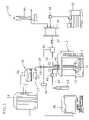
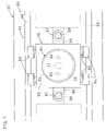
- FIG. 1is an explanatory diagram of an apparatus for drying under reduced pressure using microwaves according to a first embodiment of the present invention.
- FIG. 2is an explanatory diagram of a main part of the apparatus.
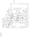
- FIG. 3is an explanatory diagram of an apparatus for drying under reduced pressure using microwaves according to a second embodiment of the present invention.
- FIG. 4is an explanatory diagram of an apparatus for drying under reduced pressure using microwaves according to a modification of the second embodiment of the present invention.
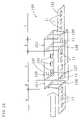
- FIG. 5is an explanatory diagram of an apparatus for drying under reduced pressure using microwaves according to a third embodiment of the present invention.
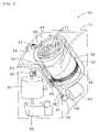
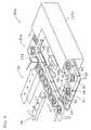
- FIG. 6is a cross-sectional view showing equipment arrangement around lidded trays at a depressurization start station, a microwave heating station and a pressure recovery station.
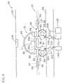
- FIG. 7is a partial plan sectional view of the lidded tray.
- FIG. 8is an arrangement diagram of the lidded trays of the apparatus according to the third embodiment of the present invention.
- FIG. 9is an explanatory diagram of an apparatus for drying under reduced pressure using microwaves according to a modification of the third embodiment of the present invention.
- FIGS. 10 (A) and 10 (B)are a front sectional view and a side sectional view, respectively, of equipment arrangement around the lidded trays at a depressurization start station, a microwave heating station and a pressure recovery station.
- FIG. 11is an explanatory diagram of an apparatus for drying under reduced pressure using microwaves according to another modification of the third embodiment of the present invention.
- FIG. 12is an explanatory diagram of an apparatus for drying under reduced pressure using microwaves according to a fourth embodiment of the present invention.
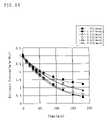
- FIG. 13is a graph showing the relationship between drying time and moisture contents of objects when a chamber of the apparatus for drying under reduced pressure using microwaves is maintained at different pressures.
- FIG. 14is a graph showing the relationship between the drying time and the moisture contents of the objects when a gas is supplied to the chamber at different flow rates.
- FIG. 15is a graph showing the relationship between the drying time and the moisture contents of the objects when different microwave irradiation methods are employed.
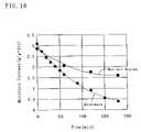
- FIG. 16is a graph showing the relationship between the drying time and the moisture contents of the objects for microwave drying and hot-air drying.
- FIGS. 17 (A) and 17 (B)are graphs showing moisture content distributions from the surfaces to inner parts of the objects dried in an empirical example (microwave drying) and in a comparative example (hot-air drying), respectively.
- FIGS. 18 (A), 18 (B) and 18 (C)are explanatory diagrams illustrating surface tissue of the object before drying with microwaves, the surface tissue of the object after drying with microwaves, and the surface tissue of the object after drying in a comparative example, respectively.
- FIGS. 1 and 2an apparatus 10 for drying under reduced pressure using microwaves according to a first embodiment of the present invention will be described.
- the apparatus 10includes a microwave oven 12 , an example of a microwave irradiating device for irradiating microwaves to an object (e.g., a scallop adductor muscle) 11 .
- a chamber 13is disposed for housing the object 11 .
- the chamber 13is formed by a plate glass 14 and a bell-shaped glass container 15 mounted on the plate glass 14 .
- the chamber 13is hermetically sealed when the inside thereof is reduced in pressure.
- food as the objectmay be selected from, e.g., raw materials for dried goods comprising one or more of abalones, fishes, shiitake mushrooms, etc.; fruits as raw materials for dried fruits; vegetables used in health foods, instant foods, etc.; and food waste used as livestock feed, such as vegetable and fish scraps discharged from markets or the like.
- a deterioration temperature for drying the foodis a denaturation temperature (or a decomposition temperature) of constituents of the food, e.g., proteins, starches, vitamins, etc.
- the object to be driedmay be selected from heat-deformable articles such as washed clothes, lumber, glass whereon a liquid crystal film is deposited, rinsed electronic boards whereon electronic components are mounted, and paper used as an insulator in electronic components such as capacitors.
- the deterioration temperature of clothesis a temperature at which cloth of the clothes is damaged or shrinks.
- the deterioration temperature of lumber or glassis a temperature at which a crack or a warp occurs on the lumber or the glass.
- the deterioration temperature of electronic boardsis a temperature at which electronic components thereof are damaged or deformed.
- the deterioration temperature of paperis a temperature at which the paper deforms.
- the use of the apparatus 10also allows dehydration of sludge such as sewage sludge, livestock excreta, etc., and drying of applied coating materials without causing deterioration (destruction of the composition and burning) and deformations.
- sludgesuch as sewage sludge, livestock excreta, etc.
- the microwave oven 12generates microwaves having a frequency of 2450 MHz (2.45 GHz) by a magnetron not shown, an example of a microwave generating unit provided in the microwave oven 12 .
- the “microwaves”is a generic term to represent electromagnetic waves having a wavelength of about 1 to 30 cm and a frequency in a range of 1000 MHz to 30 GHz.
- the microwavesare used in radars, telephones, telecasts, etc., and serve an important role in studies of molecular structures of substances.
- the microwavespenetrate glass, paper, etc., and are reflected by metals but easily absorbed by water.
- the microwave oven 12By the microwave oven 12 , the microwaves generated from the magnetron are applied to the object 11 , thereby vibrating water molecules in the object 11 . Consequently, only the water in the object 11 is heated and evaporated, whereby the object 11 is dried. Microwave drying allows traveling directions of both the water and heat to be directed from the interior to the exterior of the object 11 , and thus drying efficiency is improved.
- the microwave irradiating (radiating) devicemay be a waveguide, an antenna, or the like.
- thermometers 16 and 17capable of measuring temperature under high-frequency or high-voltage conditions are preferably used. Temperatures on the surface and inside the object 11 are measured by the thermometers 16 and 17 , respectively.
- the glass container 15has through-holes 20 , 21 , a gas outlet 24 , and a gas intake 25 at an upper portion thereof. Sensors 18 and 19 of the thermometers 16 and 17 are inserted in the chamber 13 through the through-holes 20 and 21 , respectively.
- Attached to the gas outlet 24is an exhaust pipe 23 connected to a depressurizing pump (e.g., vacuum pump) 22 for depressurizing the inside of the chamber 13 .
- the gas intake 25is provided for introducing air (an example of a gas) into the chamber 13 .
- the gas (carrier gas) supplied through the gas intake 25may be air, nitrogen, or the like, and the carrier gas allows water evaporated by microwave irradiation to be discharged out of the chamber 13 . The removal of water in the chamber 13 in this way reduces humidity inside the chamber 13 , thereby promoting dehydration of the object 11 .
- the thermometers 16 and 17respectively have thermometer controllers 26 and 27 disposed outside the microwave oven 12 .
- the sensors 18 and 19 for directly measuring the temperatures of the object 11are connected to the thermometer controllers 26 and 27 , respectively.
- the sensors 18 and 19respectively include sensor portions 28 and 29 , and coated fiber-optic cables (hereafter referred to as cables) 30 and 31 .
- the sensor portions 28 and 29have fiber optics inside and distal ends thereof are applied with thin film of a fluorescent material (e.g., magnesium-based phosphor) not shown.
- the cables 30 and 31connect the thermometer controllers 26 , 27 to the sensors 28 , 29 , respectively.
- the microwave oven 12is provided with through-holes 32 and 33 through which the cables 30 and 31 pass, respectively, so that the cables 30 and 31 are connected respectively to the thermometer controllers 26 and 27 disposed outside the microwave oven 12 .
- the temperatures of the object 11are measured by flashing a flashlight on the fluorescent material on the sensor portions 28 and 29 respectively from the thermometer controllers 26 and 27 via the fiber optics, and then measuring decay of fluorescent brightness that changes with temperature (i.e., fluorescent decay time).
- the sensor portions 28 and 29 in a needle-like formare employed so that they can be placed on the surface and inside the object 11 , respectively.
- the thermometer controllers 26 and 27are connected to a measurement station 34 which stores measured data.
- a computer 35is connected to the measurement station 34 .
- the computer 35is an example of a control device for analyzing the data stored on the measurement station 34 and turning on and off the microwave irradiation by the microwave oven 12 based on the analysis of the measured values of the thermometers 16 and 17 .
- the computer 35performs temperature control in the following manner.
- the computer 35stops the microwave irradiation by controlling the microwave oven 12 when the analyzed data reaches a specific temperature “A”, which is below a denaturation temperature of the object 11 .
- the computer 35After the suspension of the microwave irradiation, when the analyzed data reaches a specific temperature “B” (e.g., 30° C.), which is in the vicinity of or higher than a saturation temperature corresponding to a pressure in the chamber, the computer 35 resumes the microwave irradiation to the object 11 by controlling the microwave oven 12 . Since the object 11 is the scallop adductor muscle in this embodiment, the specific temperature “A” was set to 40° C., which is below the denaturation temperature of the scallop adductor muscle, i.e., about 42° C.
- the pipe 23connects the inside of the chamber 13 to the depressurizing pump 22 .
- a pressure sensor 36 , an open/close valve 37 , a vacuum tank 38 , and a pressure-regulating valve 39are attached to the pipe 23 between the microwave oven 12 and the depressurizing pump 22 in order from the upstream (from the microwave oven side).
- the pressure sensor 36is connected to the measurement station 34 via an amplifier 40 , and pressure values measured by the pressure sensor 36 at predetermined time intervals are stored on the measurement station 34 .
- a mercury manometer 41 for measuring the pressure in the vacuum tank 38is connected to the vacuum tank 38 .
- the microwave oven 12is formed with a through-hole 42 through which the exhaust pipe 23 passes.
- a suction pipe 43is connected for supplying air outside the microwave oven 12 into the chamber 13 .
- a flowmeter 44 disposed outside the microwave oven 12is connected to the other end of the suction pipe 43 .
- the microwave oven 12is formed with a through-hole 45 through which the suction pipe 43 passes, and the suction pipe 43 is provided with a flow-regulating valve 46 . Because the inside of the chamber 13 is depressurized by the depressurizing pump 22 , opening the flow-regulating valve 46 allows the air outside the microwave oven 12 to be supplied into the chamber 13 through the suction pipe 43 . The supplied air forms a current around the object 11 , thereby promoting dehydration of the object 11 .
- the suction pipe 43 , the flowmeter 44 , the flow-regulating valve 46 with an inlet open to the outside air and the depressurizing pump 22form an airflow generating device, and depressurization of the inside of the chamber 13 by the depressurizing pump 22 allows the outside air passing through the flowmeter 44 and the flow-regulating valve 46 to be admitted into the chamber 13 .
- the flow-regulating valve 46is regulated considering performance of the depressurizing pump 22 so that the pressure in the chamber 13 is maintained at or below the saturated vapor pressure corresponding to the specific temperature “A”. (This operation is also conducted in embodiments described below.)
- the air evacuated from the chamber 13 by the depressurizing pump 22 and the air supplied to the chamber 13 through the suction pipe 43are regulated by the pressure-regulating valve 39 and the flow-regulating valve 46 , respectively.
- the water in the chamber 13 evaporated by the microwave irradiationis discharged from the chamber 13 through the gas outlet 24 and the exhaust pipe 23 . Removal of the water in the chamber 13 in this way reduces humidity in the chamber 13 and further promotes dehydration of the object 11 .
- the through-holes 20 , 21 , the gas outlet 24 , and the gas intake 25 formed on the glass container 15 , and the through-holes 32 , 33 , 42 , 45 formed on the microwave oven 12are sealed up by O-rings, sealing resin, or the like not shown. Because the through-holes 20 , 21 , the gas outlet 24 , and the gas intake 25 are sealed, depressurization of the inside of the chamber 13 brings the plate glass 14 and the glass container 15 in close contact, whereby the inside of the chamber 13 is hermetically sealed. Grease may be applied on contact surfaces of the plate glass 14 and the glass container 15 before bringing them into close contact.
- the sensor portion 28 of the thermometer 16 and the sensor portion 29 of the thermometer 17are respectively placed on the surface and inside the object 11 , and the object 11 is placed in the chamber 13 .
- the air in the chamber 13is evacuated by the depressurizing pump 22 .
- the air in the chamber 13is evacuated by the depressurizing pump 22 with the flow-regulating valve 46 opened, so that the external air is supplied into the chamber 13 through the gas intake 25 .
- the inside of the chamber 13is maintained at or below the saturated vapor pressure at the specific temperature “A”, e.g., maintained at a reduced pressure of 50 to 150 mmHg (6.7 to 20.0 kPa). Because the inside of the chamber 13 is reduced in pressure, evaporation temperature of water decreases.
- the object 11can be dried at low temperatures.
- the object 11is the scallop adductor muscle and the specific temperature “A” is set to 40° C., which is below the denaturation temperature (about 42° C.) of the object 11 , i.e., the scallop adductor muscle.
- the chamber 13is depressurized by the depressurizing pump to or below 7.376 kPa, which is the saturated vapor pressure at the specific temperature “A”.
- the microwavesare generated and applied to the object 11 by the microwave-generating unit of the microwave oven 12 to heat the object 11 .
- the microwave irradiation to the object 11the water molecules in the object 11 are made to vibrate and produce heat. Because of the heat, the water in the object 11 evaporates.
- the microwave irradiation by the microwave oven 12is stopped by a signal from the computer 35 . This prevents the object 11 from being heated to or above its denaturation temperature and the object 11 can be dried without being deteriorated.
- the object 11is cooled and the temperature thereof is reduced by latent heat of the water evaporated by the microwave irradiation.
- a specific temperature “B”e.g., 30° C.
- the microwave oven 12is turned on by a signal from the computer 35 . Thereby, microwave irradiation to the object 11 is resumed to heat the object 11 .
- the object 11is dried by the temperature control through intermittent irradiation of the microwaves.
- the intermittent irradiation of the microwavesis to repeat a step of suspending the microwave irradiation when the temperature of the object 11 increases to the specific temperature “A” by the microwave irradiation, and a step of resuming the microwave irradiation when the temperature of the object 11 lowers to the specific temperature “B” by the latent heat of water evaporated by the microwave irradiation.
- the airis supplied into the chamber 13 through the gas intake 25 by opening the flow-regulating valve 46 , generating the airflow around the object 11 . Consequently, dehydration of the object 11 is promoted. Furthermore, the water evaporated from the object 11 and released in the chamber 13 is discharged out of the chamber 13 through the gas outlet 24 . At this time, the humidity in the chamber 13 is reduced, which further promotes dehydration of the object 11 .
- the temperature of the gas supplied from the chamber 13 to the depressurizing pump 22is also not increased. Furthermore, the gas is admitted into the chamber by the airflow generating device. Thereby, relative humidity of the exhaust gas is maintained at or below 95% and the life of the depressurizing pump 22 can be extended.
- FIG. 3an apparatus 50 for drying under reduced pressure using microwaves according to a second embodiment of the present invention will be described.
- the same components as those of the apparatus 10are represented by the same reference numerals and the detailed description thereof is omitted (the same is also true in the following embodiments).
- the apparatus 50includes a hermetically sealable, cylindrical chamber 52 disposed in a casing 51 .
- the chamber 52is provided with a microwave generating unit 53 , an example of a microwave irradiating device for irradiating microwaves toward the interior of the chamber 52 .
- the apparatus 50further includes a computer not shown, an example of a control device.
- the computercontrols microwave irradiation time in a manner that the microwaves are irradiated from the microwave generating unit 53 to the objects (scallop adductor muscles) 11 in a predetermined cycle so that the temperature of the objects does not exceed the specific temperature “A” (40° C.), which is below the denaturation temperature (deterioration temperature) of the object 11 .
- the chamber 52is disposed in a manner that the central axis thereof is tilted at e.g. 30 degrees to the vertical axis so that the objects 11 in the chamber 52 are stirred appropriately.
- the casing 51is open at the top thereof, and a door 54 through which the objects 11 are supplied to the chamber 52 is provided at the top of the casing 51 .
- the chamber 52is provided with a lid (not shown) for sealing the chamber 52 .
- a lid portion which hermetically seals the chamber 52 when the door 54 is closedmay be formed inside the door 54 .
- a cylindrical drying container 55 for housing one or more of the objects 11is provided in the chamber 52 .
- the drying container 55is open at the top thereof and is disposed in a manner that the central axis thereof is aligned with that of the chamber 52 .
- a lateral side of the drying container 55is formed with meshes having openings in a size that does not allow the object 11 to pass through.
- the drying container 55has a large-diameter gear 56 on an outer circumferential surface of a lower portion thereof.
- the gear 56is provided with a small-diameter drive gear 57 engaging therewith.
- the drive gear 57is connected to a motor 59 via a rotating shaft 58 .
- the rotating shaft 58 and a motor rotating shaft 60 of the motor 59are arranged orthogonal to each other.
- Spiral gears 61 and 62are mounted on a proximal end of the rotating shaft 58 and a distal end of the motor rotating shaft 60 , respectively. Because of such structure, rotational drive of the motor 59 causes low-speed rotation of the drying container 55 .
- the chamber 52has a gas outlet 63 at a lower portion thereof.
- the gas outlet 63is connected to a depressurizing pump (e.g., a vacuum pump) 65 for depressurizing the inside of the chamber 52 via an exhaust pipe 64 .
- a pressure-regulating valve 66 and a condenser 67are connected to the exhaust pipe 64 from the upstream side (from a side of the chamber 52 ).
- the condenser 67is provided for condensing moisture generated in the chamber 52 and storing the condensed moisture, thereby preventing the water from entering the depressurizing pump 65 .
- the chamber 52is provided with a gas intake 69 at an upper portion thereof.
- a suction pipe 68 for introducing the air (an example of the gas) from the outside of the casing 51 to the inside of the chamber 52is connected to the gas intake 69 .
- a flow-regulating valve 70 for regulating the airflow admitted into the chamber 52is provided in the middle of the suction pipe 68 .
- a downstream end portion of the suction pipe 68is fixed to the cylindrical chamber 52 in a direction tangential to an outer circumference thereof.
- the air from the gas intake 69flows into the chamber 52 in a direction substantially tangential to a sidewall of the chamber 52 and forms a swirling flow “a” (i.e., airflow) around the exterior of the drying container 55 housing the objects 11 .
- the suction pipe 68 and the flow-regulating valve 70are included in an airflow generating device.
- the swirling flow “a” generated by the airflow generating deviceenters the drying container 55 through the meshes thereof and comes into contact with the objects 11 , thereby accelerating dehydration of the objects 11 .
- the water evaporated from the objects 11 in the chamber 52is exhausted out of the chamber 52 from the gas outlet 63 together with the swirling flow “a”. At this time, humidity in the chamber 52 is reduced, which further promotes dehydration of the objects 11 .
- a plurality of the objects 11are placed in the drying container 55 .
- the lid of the chamber 52is closed to hermetically seal the chamber 52 and the door 54 is closed.
- the flow-regulating valve 70is opened to supply the outside air into the chamber 52 through the gas intake 69 , and the inside of the chamber is depressurized, e.g. to 50 to 150 mmHg (6.7 to 20.0 kPa, more specifically to 7.376 kPa).
- the amount of the air evacuated by the depressurizing pump 65is regulated by the pressure-regulating valve 66
- the amount of the air introduced into the chamber 52is regulated by the flow-regulating valve 70 .
- microwave generating unit 53is controlled by the computer so that the microwaves are irradiated intermittently from the microwave generating unit 53 in a cycle, thereby rapidly heating the objects 11 in the pulsing manner.
- the specific temperature “A” for drying the objects 11is set below about 42° C., which is a denaturation temperature of protein, e.g., to 40° C.
- the cycle of intermittent irradiation of the microwavesincludes microwave irradiation time “a” (ON) and microwave non-irradiation time “b” (OFF).
- the irradiation time “a” and the suspension time “b” for maintaining the temperatures of the objects 11 at or below the specific temperature “A”are determined beforehand through experiments. Accordingly, the objects 11 are heated at temperatures lower than the denaturation temperature thereof, and thus the objects 11 can be dried without being denatured.
- the objects 11are cooled and the temperatures thereof are lowered by latent heat of the water in the objects 11 .
- the latent heatis generated through evaporation of the water by heating the objects 11 to the specific temperature “A” with the microwave irradiation.
- the microwavesare irradiated to the objects 11 again to heat the objects 11 to the specific temperature “A” for drying the objects 11 .
- the irradiation time “a”is, e.g., 0.5 sec. to several minutes, preferably one to several sec. although the time varies depending on the object.
- the suspension time “b”may be equal to or different from the irradiation time “a”. Rapid heating of the objects 11 in the pulsing manner causes the water in the objects 11 to move toward the surfaces of the objects 11 after the moisture on the surfaces of the objects 11 is evaporated. As a result, drying efficiency is improved.
- the wateris exhausted from the gas outlet 63 along with the swirling flow “a” having passed through the chamber 52 , and then the water is condensed by the condenser 67 . Therefore, the water does not enter the depressurizing pump 65 , whereby the life of the depressurizing pump 65 can be extended. Moreover, because the objects 11 are rotated by the motor 59 , drying efficiency is improved. It is preferable to rotate the drying container 55 in a direction opposite to a swirling direction of the swirling flow “a” so that the objects 11 can be easily brought into contact with the air.
- FIG. 4an apparatus 71 for drying under reduced pressure using microwaves according to a modification of the second embodiment of the present invention will be described.
- the apparatus 71includes a hermetically sealed cylindrical chamber 72 .
- a microwave generating mechanism 74 having a microwave generating unit not shownis attached to the chamber 72 via a waveguide 73 .
- the microwave generating mechanism 74 and the waveguide 73form a microwave irradiating device.
- the chamber 72has a sealing lid not shown at an upper portion thereof through which objects to be dried are supplied into the chamber 72 and dried objects are discharged from the chamber 72 . It is optional to provide the chamber 72 with a tray or the like for carrying the objects.
- the chamber 72forms a part of an airflow generating device.
- the chamber 72is provided with a gas intake 75 (preferably having a flow regulating valve) for introducing the gas from the outside to the inside of the chamber 72 , and a depressurizing pump 77 for reducing the pressure in the chamber 72 to a range of e.g. 50 to 150 mmHg through a vent tube 76 .
- the chamber 72is provided with a manometer 78 and a thermometer 79 for respectively measuring pressure and temperature in the chamber 72 .
- the apparatus 71includes a control device 79 a .
- the control device 79 aperforms on/off control of the microwave generating unit and the depressurizing pump 77 while maintaining the temperature in the chamber 72 , namely the temperature of the objects in the chamber 72 , below the denaturation temperature of the object by analyzing data from the manometer 78 and the thermometer 79 . Because of such structure, the objects are heated below the denaturation temperature thereof, and accordingly the objects can be dried without being denatured.
- FIGS. 5 to 8an apparatus 80 for drying under reduced pressure using microwaves according to a third embodiment of the present invention will be described.
- the apparatus 80includes a plurality of (e.g., 18) lidded trays 81 , examples of chambers for housing the objects 11 .
- each of the trays 81is made of a material that reflects microwaves, for example, a metal (specifically, stainless steel).
- the tray 81has a tray body 82 for carrying the object 11 and a hemispheric lid 83 for covering the top of the tray body 82 .
- the lid 83is made of a microwave permeable material, e.g., quartz glass.
- the tray 81is designed such that the lid 83 is openable and closable by an opening and closing mechanism not shown.
- the tray body 82is formed on a bottom thereof with an exhaust pipe connecting port 84 and a gas induction pipe connecting port 85 .
- the connecting ports 84 and 85are provided with female couplers (pipe coupling devices) 86 and 87 , respectively. Each of the couplers 86 and 87 has an open/close valve that is usually closed.
- the apparatus 80includes a pair of endless rails (hereafter simply referred to as rails) 88 and 89 disposed with a constant distance therebetween, and a conveyor 91 having eighteen carriages 90 .
- the linked carriages 90are disposed over the rails 88 , 89 and are arranged throughout the lengths of the rails 88 and 89 .
- the trays 81are respectively fixed on the carriages 90 , and the trays 81 are conveyed intermittently by a certain distance (the number of the carriages/a length of a rail path) by the conveyor 91 .
- the conveyor 91has eighteen stop positions and the trays 81 are stopped sequentially at the respective stop positions.
- Each of the carriages 90comprises four wheels 94 and a plate-shaped carriage body 92 for carrying the tray 81 .
- the wheels 94are disposed at both ends of two shafts 93 mounted at front and rear of the carriage body 92 , and run on the rails 88 and 89 .
- the carriage body 92has links 95 and 96 at the front and rear thereof for connecting adjacent carriages 90 .
- Each of the links 95 and 96is formed with a shaft hole 98 in which a connecting pin 97 is fitted so that the carriages 90 can travel smoothly on the rails 88 and 89 .
- the conveyor 91is provided with a drive unit not shown for intermittently conveying the carriages 90 .
- the drive unitmay be mounted on each of the carriages 90 or the drive unit may be a conveying unit that conveys the carriages 90 by a predetermined distance through actuation of a cylinder.
- the conveyor 91has a feed station “A” where the object 11 is supplied from a feed conveyor 99 onto the tray 81 .
- the object 11 conveyed by the feed conveyor 99is placed on the tray body 82 with the lid 83 opened.
- a sealing station “B”is provided downstream of the feed station “A” in a traveling direction.
- the sealing station “B”has four stop positions where the lid is covered on the tray body 82 . Although four stop positions are employed in this embodiment, one or two stop positions may be used to conduct entire lid closing operation.
- a depressurization start station “C”is provided downstream of the sealing station “B” in the traveling direction.
- male couplers 102 and 105are provided beneath the conveyor 91 as illustrated in FIG. 6 (a microwave generating unit 106 is not provided at the station “C”).
- the male coupler 102is connected to the depressurizing pump 100 and is moved up and down by an elevating mechanism 101 .
- the male coupler 105is connected to a flow-regulating valve 103 provided for introducing the outside air, and is moved up and down by an elevating mechanism 104 .
- the couplers 102 and 105are united with the female couplers 86 and 87 , respectively.
- the couplers 102 and 105When the male couplers 102 and 105 are lowered by the elevating mechanisms 101 and 104 , respectively, the couplers 102 and 105 are detached from the female couplers 86 and 87 , respectively. At this time, passages in the female couplers 86 and 87 are closed. Because of such structure, the tray 81 is depressurized when the tray 81 is temporarily stopped at the station “C”. At this time, if necessary, an airflow may be generated in the tray 81 by opening the flow-regulating valve 103 .
- the flow-regulating valve 103 , the female coupler 87 , the male coupler 105 , the gas induction pipe connecting port 85 and the depressurizing pump 100form an airflow generating device.
- reference numerals 84 a and 84 bdenote exhaust pipes
- reference numerals 85 a and 85 bdenote blast pipes.
- the couplers with shutoff valves(the female and male couplers 86 , 102 ) are provided between the exhaust pipes 84 a and 84 b
- the couplers with shutoff valvesare provided between the blast pipes 85 a and 85 b . Since the respective pairs of the couplers are connected to or detached from each other by the elevating mechanisms 101 and 104 , respectively, it is preferable to use couplers without retaining rings.
- a microwave heating station “D” having seven stop positionsis provided downstream of the depressurization start station “C.” in the traveling direction.
- the tray 81is depressurized to a certain extent and then the male couplers 102 and 105 are lowered to detach the couplers 102 and 105 from the female couplers 86 and 87 . Subsequently the tray 81 is conveyed to the station “D”.
- the male coupler 102 and the female coupler 105are provided beneath each of the seven stop positions.
- the male coupler 102is connected to the depressurizing pump 100 and is moved up and down by the elevating mechanism 101 .
- the male coupler 105is connected to the flow-regulating valve 103 for introducing outside air and is moved up and down by the elevating mechanism 104 .
- the airflow generating deviceis operated to generate the airflow around the object 11 while the inside of the tray 81 is depressurized.
- the elevating mechanisms 101 and 104are operated to connect the male couplers 102 , 103 to the female couplers 86 , 87 , respectively, or to detach the male couplers 102 , 103 from the female couplers 86 , 87 , respectively.
- the microwave generating unit 106At each stop position in the station “D”, the microwave generating unit 106 , an example of a microwave generating device, is provided above the tray 81 . Furthermore, at the station “D”, a casing 107 is provided for preventing a leakage of the microwaves generated from the microwave generating unit 106 to the outside.
- the microwavesare irradiated intermittently in a predetermined cycle so that the temperature of the object 11 in the tray 81 is maintained below the deterioration temperature of the object 11 .
- experimentsare conducted for the objects 11 to determine the intermittent irradiation cycle and power of the microwaves which maintain the temperature of the object 11 within a prescribed range (e.g., between the specific temperatures A and B). The experiments are performed under the same conditions (the same or improved apparatus of the first embodiment may be used), and temperatures of the objects 11 irradiated with the microwaves are measured.
- the tray 81 housing the object 11 that was subjected to a predetermined drying treatment at the station “D”is conveyed to a pressure recovery station “E”.
- the male coupler 105 provided with the flow-regulating valve 103 and the elevating mechanism 104 for elevating and lowering the coupler 105are provided below the station “E” as illustrated in FIG. 6 .
- the microwave generating unit 106 , the depressurizing pump 100 , the elevating mechanism 101 and the male coupler 102are not provided at the station “E”. Air is introduced from the outside to the inside of the tray 81 via the flow-regulating valve 103 .
- the tray 81is subsequently conveyed to an opening station “F”, where the lid 83 is opened.
- the tray 81is then conveyed intermittently to a discharge station “G”, where the dried object 11 on the tray body 82 is discharged from the tray body 82 via a discharge conveyor 108 .
- a guide 109may be provided for guiding the object 11 to the outside in accordance with the movement of the carriages 90 .
- the tray 81is emptied by the above operation and is conveyed to a feed preparation station “H”, where the tray body 82 is cleaned, and then the tray 81 is conveyed to the station “A”.
- the intermittent conveying operation of the carriages 90 as described aboveare repeated to continuously dry a multiplicity of the objects 11 .
- FIGS. 9 , 10 (A), and 10 (B)an apparatus 80 a for drying under reduced pressure using microwaves according to a modification of the third embodiment of the present invention will be described.
- the apparatus 80 aincludes the lidded trays 81 each having the tray body 82 and the lid 83 .
- the tray body 82is provided with the exhaust pipe connecting port 84 and the gas induction pipe connecting port 85 at the bottom portion thereof.
- the eighteen trays 81are mounted on a chain conveyor 91 a (an example of a conveyor).
- the apparatus 80 ahas the feed station “A”, sealing station “B”, depressurization start station “C”, microwave heating station “D”, pressure recovery station “E”, opening station “F”, discharge station “G”, and feed preparation station “H”.
- the blast pipe 85 a having a flow-regulating valve 87 a at a distal portion thereofis connected to the gas induction pipe connecting port 85 .
- the exhaust pipe 84 a having an open/close valve (an electromagnetic valve) 86 ais connected to the exhaust pipe connecting port 84 .
- An endless flexible tube 95 ais connected to a distal portion of the exhaust pipe 84 a provided to the tray body 82 of each of the eighteen trays 81 .
- the flexible tube 95 ais connected to a depressurizing pump 100 a via a pump tube 96 a and a rotary joint not shown. The rotary joint prevents the tube 96 a from being tangled when the trays 81 are rotationally conveyed.
- a signal line (not shown) for opening and closing the valve 86 a provided to each of the tray bodies 82is disposed along the tube 96 a .
- the signal lineis connected via the rotary joint to a control device 100 b provided adjacent to the depressurizing pump 100 a .
- Signals from the control device 100 bopen the valves 86 a connected to the trays 81 located at the depressurization start station C and the microwave heating station D, depressurize the inside of the trays 81 , and furthermore, supply the outside air into the trays 81 through the ports 85 .
- a casing 107 a of the discharge station Ddiffers from the casing 107 of the apparatus 80 in the following point.
- the casing 107 ais open at inner lower sides thereof so as to allow smooth movements of the pump tube 96 a connected to the trays 81 conveyed by the chain conveyor 91 and the signal line provided along the tube 96 a.
- the control device 100 bgenerates signals for, besides opening/closing control of the valves 86 a , drive of the chain conveyor 91 a , opening/closing of the lids 83 of the trays 81 , and on/off control of the microwave generating unit 106 according to a program.
- Operations at the respective stations A through H of the apparatus 80 aare basically the same as those of the apparatus 80 , and thus detailed explanation on the operations are omitted.
- FIG. 11an apparatus 110 for drying under reduced pressure using microwaves according to another modification of the third embodiment of the present invention will be described.
- a carriage 112 of a conveyor 111is a doughnut-shaped plate. On the carriage 112 , there are mounted a plurality of, e.g. eight, trays 81 at predetermined intervals.
- the apparatus 110are divided sequentially into a feed station “a”, a sealing and depressurizing station “b”, a microwave heating station “c”, a pressure recovery station “d”, an opening station “e”, and a discharge station “f” where the object 11 is discharged.
- the object 11is fed onto the tray 81 from the feed conveyor 99 .
- the lid 83 of the tray 81is closed, and then air in the hermetically sealed tray 81 is evacuated by the depressurizing pump 100 (see FIG. 6 ).
- the microwave heating station “c”the tray 81 that has been depressurized is conveyed into a casing 113 having a microwave generating unit (not shown) inside. While the inside of the tray 81 is depressurized and the airflow is generated, the microwaves are irradiated to the object 11 from the microwave generating unit not shown to dry the object 11 .
- the pressure in the tray 81 came out of the casing 113is returned to atmospheric pressure.
- the lid 83 of the tray 81is opened, and then at the discharge station “f”, the dried object 11 in the tray 81 is discharged onto the conveyor 108 .
- three of the trays 81are located at the microwave heating station and one of the tray 81 is located at each of the other stations.
- FIG. 12an apparatus 120 for drying under reduced pressure using microwaves according to a fourth embodiment of the present invention will be described.
- the apparatus 120has a roller conveyor (hereafter simply referred to as a conveyor) 121 for conveying the objects 11 , a microwave drying chamber (an example of a chamber) 123 , a preliminary decompression chamber 124 positioned upstream of the drying chamber 123 , and a pressure recovery chamber 125 positioned downstream of the drying chamber 123 .
- the drying chamber 123is provided with microwave generating units 122 for irradiating the microwaves to the objects 11 conveyed via the conveyor 121 in a reduced-pressure state.
- the decompression chamber 124 , the drying chamber 123 , and the pressure recovery chamber 125 connected in succession from the upstream of the conveyor 121have doors 126 to 129 .
- the doors 126 to 129are provided at an inlet on the upstream side of the decompression chamber 124 , between the decompression chamber 124 and the drying chamber 123 , between the drying chamber 123 and the pressure recovery chamber 125 , and at an inlet on the downstream side of the pressure recovery chamber 125 , respectively.
- the doors 126 to 129allow passage of the objects 11 and hermetically seal the chambers 124 , 123 , and 125 .
- Sections of the conveyor 121 at the chambers 124 , 123 and 125are respectively designed to have lengths in the traveling direction for placing, e.g., one object 11 , three objects 11 , and one object 11 , on the conveyor 121 at predetermined intervals.
- a depressurizing pump not shownis connected to each of the chambers 124 , 123 and 125 .
- the drying chamber 123has a plurality of (e.g., three) microwave generating units 122 at predetermined intervals, a gas intake not shown for introducing a gas (e.g., air) from the outside to the inside of the drying chamber 123 , and a fan 130 for generating airflow around the objects 11 by stirring the gas in the chamber 123 .
- a gase.g., air
- the apparatus 120performs the intermittent irradiation of the microwaves by a computer not shown, an example of a control device. Namely, the microwaves are irradiated to the objects 11 from the microwave generating units 122 in a predetermined cycle so that the temperatures of the objects 11 are maintained lower than the deterioration temperature of the object 11 . Besides the intermittent irradiation of the microwaves, the computer also controls conveying speed of the conveyor 121 , opening and closing of the doors 126 to 129 , operation of the fan 130 and operation of the depressurizing pumps.
- the conveyor 121is divided sequentially from the upstream side into the feed station “A” on an upstream side of the door 126 , a depressurizing station “B” in the chamber 124 , a heating station “C” in the chamber 123 , a pressure recovery station “D” in the chamber 125 , and a discharge station “E” on a downstream side of the door 129 .
- the sections of the conveyor 121 at the respective stationsare operable separately.
- the doors 127 and 128are closed and the microwave drying chamber 123 is depressurized by the depressurizing pump. It is preferable that the chamber 123 is always maintained under reduced pressure. Then, the door 126 is opened, and the sections of the conveyor 121 at the stations “A” and “B” are operated to convey the object 11 to the chamber 124 . Subsequently, the door 126 is closed and the inside of the chamber 124 is depressurized by the depressurizing pump.
- the door 127is opened and the sections of the conveyor 121 at the stations “B” and “C” are operated to convey the object 11 into the chamber 123 .
- the door 127is closed and the drying chamber 123 is hermetically sealed. While the microwaves are irradiated to the object 11 from the microwave generating units 122 , the gas is introduced from the outside into the chamber 123 via the gas intake and the fan 130 is operated to generate the airflow around the object 11 , thereby drying the object 11 .
- the inside of the pressure recovery chamber 125is depressurized to a predetermined pressure by the depressurizing pump with the door 129 closed.
- the door 128is opened, the sections of the conveyor 121 at the stations “C” and “D” are operated to convey the object 11 to the chamber 125 , and the door 128 is closed. Then, the operation of the depressurizing pump of the chamber 125 is stopped and the pressure in the chamber 125 is returned to near normal pressure (atmospheric pressure).
- the door 129is opened and the sections of the conveyor 121 at the stations “D” and “E” are operated to discharge the object 11 to the station “E”. After the object 11 is discharged from the chamber 125 , it is preferable to depressurize the chamber 125 with the door 129 closed.
- the objects 11can be dried by the apparatus 120 .
- a plurality of the objects 11can be dried by continuously conveying the objects 11 at predetermined intervals by the conveyor 121 .
- the roller conveyoris used as the conveyor in the above embodiment, however, a belt conveyor or a chain conveyor capable of conveying the objects while sealing the chambers 123 , 124 and 125 may be employed.
- the objects 11were dried by microwave irradiation using the apparatus 10 to which the method for drying under reduced pressure according to the first embodiment is applied.
- the flow-regulating valve 46 of the apparatus 10was closed, and the open/close valve 37 and the pressure-regulating valve 39 were opened.
- the inside of the chamber 13was depressurized to 50, 100 and 150 mmHg by the depressurizing pump 22 .
- the specific temperatures “A” and “B”were set to 40° C. and 30° C., respectively.
- the objects 11were heated and dried in the pulsing manner at respective pressures, and the moisture contents thereof were measured at predetermined times.
- the moisture contentis a value calculated by dividing weight (g) of the water in the object by weight (g-dry) of the thoroughly dried object (the same is true in the following examples). As shown in FIG. 13 , the lower the pressure in the chamber 13 was (50 mmHg), the larger the water reducing rate of the object became.
- the objects 11were dried by microwave irradiation using the apparatus 10 .
- the flow-regulating valve 46 of the apparatus 10was opened, and the open/close valve 37 and the pressure-regulating valve 39 were opened.
- the inside of the chamber 13was depressurized to 50 mmHg by the depressurizing pump 22 .
- Flow rates of the air (an example of the gas) supplied into the chamber 13were set to 0, 1.0, 1.5, 2.0, 2.5, and 3.0 L/min., and the specific temperatures “A” and “B” were set to 40° C. and 30° C., respectively.
- the objects 11were heated and dried in the pulsing manner at respective air flow rates, and the moisture contents thereof were measured at predetermined times.
- the moisture content at the air flow rate of 0 L/minis the same as that in the Empirical Example 1. As shown in FIG. 14 , the air supply into the chamber 13 improved drying efficiency. Furthermore, drying with the air supplied into the chamber 13 at the flow rates of 1.0 and 1.5 L/min showed better results.
- the object 11was dried by microwave irradiation using the apparatus 10 .
- the flow-regulating valve 46 of the apparatus 10was opened, and the open/close valve 37 and the pressure-regulating valve 39 were opened.
- the inside of the chamber 13was depressurized to 50 mmHg by the depressurizing pump 22 .
- the flow rate of the air supplied into the chamber 13was set to 1.0 L/min, and the object 11 was heated and dried in the pulsing manner (same as in the case of air flow rate of 1.0 L/min in the Empirical Example 2).
- the objectwas dried under the same conditions except that the microwaves were irradiated continuously, and the moisture content of the object was measured at predetermined times. As shown in FIG.
- the drying timewas longer and more electric power was used compared with the case where the microwaves were irradiated in the pulsing manner. Furthermore, because of the continuous microwave irradiation, the temperature of the object was elevated as high as 80 to 150° C., and the object turned black in some cases.
- the object 11was dried by microwave irradiation using the apparatus 10 .
- the flow-regulating valve 46 of the apparatus 10was opened and the open/close valve 37 and the pressure-regulating valve 39 were opened.
- the inside of the chamber 13was depressurized to 50 mmHg by the depressurizing pump 22 .
- the flow rate of the air supplied into the chamber 13was set to 1.0 L/min.
- the object 11was heated and dried in the pulsing manner (same as in the case of the air flow rate of 1.0 L/min in the Empirical Example 2).
- the objectwas dried using a dryer operable to dry the object by blowing hot air into a chamber housing the object.
- the temperature and the flow rate of the hot airwere set to 40° C. and 1.0 L/min, respectively.
- the chamberwas open to the atmosphere and the inside of the chamber was at atmospheric pressure.
- the drying method of the present inventionachieved a faster drying speed compared with the drying method using hot air.
- FIGS. 18 (A) and 18 (B)respectively show tissue of the surface-layer cross-section of the object before and after drying.
- the surface tissue of the object 11did not substantially change before and after drying, and even after drying, the surface tissue of the object 11 did not shrink and moisture passages thereof were maintained. Based on this result, it is understood that the apparatus and method of the present invention achieved a faster drying speed. In the drying method using hot air as the comparative example, however, it was found that the surface tissue of the object 11 was shrunk and dense, and moisture passages were not maintained, inhibiting removal of water in the object 11 and slowing down the drying speed.
- the present inventionis not limited to these embodiments, and changes and modifications may be made without departing from the gist of the present invention.
- the present inventionincludes a case where a part of or all of the embodiments or modifications are combined.
- a fanmay be provided in the chamber for stirring the internal gas.
- the microwavesmay be irradiated by a microwave irradiating device such as a waveguide or an antenna.
- the objectis dried by rapid heating in the pulsing manner by intermittently irradiating the microwaves to the object in a predetermined cycle while the upper limit temperature of the object in the depressurized chamber connected to the depressurizing pump is maintained at or below the specific temperature “A”.
- the objectcan be dried in a short time at temperatures below the deterioration temperature of the object.
- the objectcan be rapidly dried without being deteriorated, and dried food can be produced with ease from shellfish, vegetables, fruits, meat, fish, etc.
- dryingcan be done in a short time without the cloth being damaged.
- rapid drying treatmentcan be conducted without damaging the inner part of the object.
Landscapes
- Engineering & Computer Science (AREA)
- Life Sciences & Earth Sciences (AREA)
- General Engineering & Computer Science (AREA)
- Mechanical Engineering (AREA)
- Chemical & Material Sciences (AREA)
- Food Science & Technology (AREA)
- Polymers & Plastics (AREA)
- Zoology (AREA)
- Wood Science & Technology (AREA)
- Health & Medical Sciences (AREA)
- Molecular Biology (AREA)
- Microbiology (AREA)
- Biomedical Technology (AREA)
- Biotechnology (AREA)
- General Chemical & Material Sciences (AREA)
- Chemical Kinetics & Catalysis (AREA)
- Physics & Mathematics (AREA)
- Electromagnetism (AREA)
- Marine Sciences & Fisheries (AREA)
- Nutrition Science (AREA)
- Drying Of Solid Materials (AREA)
Abstract
Description
Claims (7)
Applications Claiming Priority (3)
| Application Number | Priority Date | Filing Date | Title |
|---|---|---|---|
| JP2004117116 | 2004-04-12 | ||
| JP2004-117116 | 2004-04-12 | ||
| PCT/JP2005/007042WO2005100891A1 (en) | 2004-04-12 | 2005-04-11 | Method and apparatus for reduced pressure drying using microwave |
Publications (2)
| Publication Number | Publication Date |
|---|---|
| US20070271811A1 US20070271811A1 (en) | 2007-11-29 |
| US7665226B2true US7665226B2 (en) | 2010-02-23 |
Family
ID=35150091
Family Applications (1)
| Application Number | Title | Priority Date | Filing Date |
|---|---|---|---|
| US11/547,915Expired - Fee RelatedUS7665226B2 (en) | 2004-04-12 | 2005-04-11 | Method for drying under reduced pressure using microwaves |
Country Status (5)
| Country | Link |
|---|---|
| US (1) | US7665226B2 (en) |
| JP (1) | JP4474506B2 (en) |
| KR (2) | KR100928275B1 (en) |
| CN (1) | CN100562700C (en) |
| WO (1) | WO2005100891A1 (en) |
Cited By (35)
| Publication number | Priority date | Publication date | Assignee | Title |
|---|---|---|---|---|
| US20060288605A1 (en)* | 2005-06-23 | 2006-12-28 | Carow James P | Automatic Clothes Dryer |
| US20070151129A1 (en)* | 2005-12-30 | 2007-07-05 | Mcallister Karl D | Nebulizer system for a fabric treatment appliance |
| US20090064533A1 (en)* | 2005-06-28 | 2009-03-12 | Kazutoshi Nakiri | Washer-dryer |
| US20100132210A1 (en)* | 2007-01-25 | 2010-06-03 | Inotec Gmbh Co. Holding Und Handels-Kg | Installation for drying organic matter |
| US20100171513A1 (en)* | 2006-12-29 | 2010-07-08 | Signature Control Systems, Inc. | Wood kiln moisture measurement calibration and metering methods |
| US7941937B2 (en)* | 2002-11-26 | 2011-05-17 | Lg Electronics Inc. | Laundry dryer control method |
| US20110224474A1 (en)* | 2010-03-09 | 2011-09-15 | Kurion, Inc. | Advanced Microwave System for Treating Radioactive Waste |
| US20120086153A1 (en)* | 2010-10-06 | 2012-04-12 | Ibiden Co., Ltd. | Manufacturing methods of ceramic fired body, honeycomb structure, and exhaust gas converting device, and drying apparatus |
| US20120204440A1 (en)* | 2008-09-17 | 2012-08-16 | Slack Howard C | Method for reconditioning or processing a FCR APG-68 tactical radar unit |
| US20120304482A1 (en)* | 2010-02-10 | 2012-12-06 | Casetech Gmbh | Method for drying flexible tubular casings by microwaves |
| US20130102804A1 (en)* | 2002-12-23 | 2013-04-25 | Aldivia Sa | Chemical synthesis comprising heat treatment by intermittent dielectric heating, combined with a recycling system |
| US20150020404A1 (en)* | 2013-07-19 | 2015-01-22 | Tae Hyung Kim | Multifunctional microwave oven |
| US20150052774A1 (en)* | 2013-08-20 | 2015-02-26 | Whirlpool Corporation | Method for drying articles |
| US8991067B2 (en) | 2012-02-01 | 2015-03-31 | Revive Electronics, LLC | Methods and apparatuses for drying electronic devices |
| US20150101207A1 (en)* | 2013-10-14 | 2015-04-16 | Whirlpool Corporation | Method and apparatus for drying articles |
| US20150201651A1 (en)* | 2012-07-27 | 2015-07-23 | Buehler Gmbh | Method and apparatus for kiln drying of material for kiln drying |
| US9488564B2 (en) | 2012-11-14 | 2016-11-08 | Revive Electronics, LLC | Methods and apparatuses for detecting moisture |
| US9513053B2 (en) | 2013-03-14 | 2016-12-06 | Revive Electronics, LLC | Methods and apparatuses for drying electronic devices |
| US20160363369A1 (en)* | 2015-06-12 | 2016-12-15 | Targeted Microwave Solutions Inc. | Methods and apparatus for electromagnetic processing of phyllosilicate minerals |
| US9644891B2 (en) | 2012-02-01 | 2017-05-09 | Revive Electronics, LLC | Methods and apparatuses for drying electronic devices |
| US20170225094A1 (en)* | 2015-04-29 | 2017-08-10 | Kunming University Of Science And Technology | Microwave flash evaporation process and apparatus and use thereof |
| US20170342641A1 (en)* | 2016-05-31 | 2017-11-30 | Wuxi Little Swan Co., Ltd. | Heat Pump Mounting Box And Heat Pump Drier Or Heat Pump Washer-Drier |
| US20180112915A1 (en)* | 2016-10-25 | 2018-04-26 | NDT Engineering & Aerospace CO., LTD | Food waste dryer utilizing waste heat |
| US9970708B2 (en) | 2012-02-01 | 2018-05-15 | Revive Electronics, LLC | Methods and apparatuses for drying electronic devices |
| US20180320966A1 (en)* | 2015-11-05 | 2018-11-08 | Murat TÜRKYILMAZ | Drier with solar radiation simulation |
| US10240867B2 (en) | 2012-02-01 | 2019-03-26 | Revive Electronics, LLC | Methods and apparatuses for drying electronic devices |
| US20190161906A1 (en)* | 2017-11-28 | 2019-05-30 | Elberto Berdut-Teruel | Magnetic Induction Heating System and Dehydrator |
| US10309722B1 (en)* | 2013-03-14 | 2019-06-04 | International Research Institute Inc. | Microwave and vacuum drying device, system, and related methods |
| US10651643B2 (en) | 2013-07-10 | 2020-05-12 | Revive Electronics, LLC | Apparatuses and methods for controlling power to electronic devices |
| US10690413B2 (en) | 2012-02-01 | 2020-06-23 | Revive Electronics, LLC | Methods and apparatuses for drying electronic devices |
| US10876792B2 (en) | 2012-02-01 | 2020-12-29 | Revive Electronics, LLC | Methods and apparatuses for drying electronic devices |
| US11713924B2 (en) | 2012-02-01 | 2023-08-01 | Revive Electronics, LLC | Methods and apparatuses for drying electronic devices |
| US12215925B2 (en) | 2020-04-21 | 2025-02-04 | Revive Electronics, LLC | Methods and apparatuses for drying electronic devices |
| US12276454B2 (en) | 2020-04-21 | 2025-04-15 | Revive Electronics, LLC | Methods and apparatuses for drying electronic devices |
| US12281847B2 (en) | 2020-04-21 | 2025-04-22 | Revive Electronics, LLC | Methods and apparatuses for drying electronic devices |
Families Citing this family (44)
| Publication number | Priority date | Publication date | Assignee | Title |
|---|---|---|---|---|
| SE527166C2 (en)* | 2003-08-21 | 2006-01-10 | Kerttu Eriksson | Method and apparatus for dehumidification |
| WO2005100891A1 (en)* | 2004-04-12 | 2005-10-27 | Kitakyushu Foundation For The Advancement Of Industry, Science And Technology | Method and apparatus for reduced pressure drying using microwave |
| JP5039972B2 (en)* | 2006-03-30 | 2012-10-03 | 国立大学法人九州工業大学 | Cryopreservation method of cells or tissues |
| KR100731904B1 (en)* | 2006-08-30 | 2007-06-28 | 김순봉 | Food Waste Dryer |
| US8956673B2 (en) | 2007-08-28 | 2015-02-17 | Texas Tech University System | Method and system for preserving food |
| DK2200458T3 (en)* | 2007-10-15 | 2019-11-04 | Enwave Corp | DEVICE AND PROCEDURE FOR MICROWAVE VACUUM DRYING OF ORGANIC MATERIALS |
| KR100882298B1 (en)* | 2008-02-05 | 2009-02-10 | 이인구 | Decompression Dryer |
| US8729436B2 (en)* | 2008-05-30 | 2014-05-20 | Corning Incorporated | Drying process and apparatus for ceramic greenware |
| WO2010013583A1 (en)* | 2008-07-30 | 2010-02-04 | 国立大学法人九州工業大学 | Method for producing dry article and apparatus therefor |
| CN102149813B (en) | 2008-09-12 | 2015-05-27 | 能波公司 | Apparatus and method for dehydrating biological materials with freezing and microwaving |
| US8586899B2 (en)* | 2008-11-24 | 2013-11-19 | Jeffrey H. Mackay | Apparatus and method for mass sterilization and pasteurization of food products |
| JP5371498B2 (en)* | 2009-03-11 | 2013-12-18 | 株式会社フリーザーシステム | Continuous predrying method and freezing method, continuous predrying device and freezing device |
| JP5713596B2 (en)* | 2009-09-29 | 2015-05-07 | キヤノン株式会社 | Method for producing electrophotographic photosensitive member |
| EP2525675B1 (en) | 2010-01-18 | 2015-04-15 | Enwave Corporation | Microwave vacuum-drying of organic materials |
| JP5335724B2 (en)* | 2010-03-26 | 2013-11-06 | エスペック株式会社 | Drying processing equipment |
| JP5335725B2 (en)* | 2010-03-26 | 2013-11-06 | エスペック株式会社 | Sealed container and drying processing equipment |
| BRPI1002602A2 (en)* | 2010-05-21 | 2012-02-07 | Vieira Francisco Jose Duarte | process and equipment for sterilizing and withdrawing oxygen from liquid foods at low temperature by decompression and / or large linear or rotary accelerations |
| JP5854729B2 (en)* | 2010-10-06 | 2016-02-09 | イビデン株式会社 | Method for manufacturing ceramic fired body and method for manufacturing honeycomb structure |
| JP2012150064A (en)* | 2011-01-21 | 2012-08-09 | Hitachi-Ge Nuclear Energy Ltd | Treatment system of spent iron-exchange resin and filter sludge in nuclear power plant |
| WO2013036209A1 (en)* | 2011-09-09 | 2013-03-14 | Thailand Research Fund | System and method for cooking seafood products |
| KR101381196B1 (en)* | 2012-05-09 | 2014-04-04 | 한국에너지기술연구원 | Control system of dryer using of heat pump high frequence with vacuum |
| WO2014025328A2 (en)* | 2012-08-08 | 2014-02-13 | Nuh'un Ankara Makarnasi San. Ve Tic. A.Ş. | A manufacturing method that can be used for the production of stuffed pasta |
| JP6086421B2 (en)* | 2012-10-13 | 2017-03-01 | 西光エンジニアリング株式会社 | Low temperature vacuum stirring dryer and method for drying an object to be dried containing a low melting point material |
| US11679937B2 (en) | 2012-11-02 | 2023-06-20 | Smithfield Foods, Inc. | Multi-tier and spiral microwave oven dryers for rapid preparation of dry sausage |
| JP2014141438A (en)* | 2013-01-24 | 2014-08-07 | Sankyo:Kk | Formulation, food and drink containing novel madeira vine product |
| JP6062317B2 (en)* | 2013-04-26 | 2017-01-18 | 恵子 河▲崎▼ | Food vacuum drying method and apparatus |
| JP6116410B2 (en)* | 2013-07-04 | 2017-04-19 | 大陽日酸株式会社 | Biological material dehydration apparatus and method |
| WO2015171967A1 (en)* | 2014-05-07 | 2015-11-12 | Dry Ventures, Inc. | Self-service rescue of inundated cellphones |
| CN104236279A (en)* | 2014-08-13 | 2014-12-24 | 湖南有色新田岭钨业有限公司 | Dehydrating and drying method for scheelite concentrate and device thereof |
| CN106403514B (en)* | 2015-07-29 | 2019-03-05 | 广西梧州制药(集团)股份有限公司 | Application of convection heat transfer mode in material decompression drying process |
| KR20170020131A (en) | 2015-08-13 | 2017-02-22 | 황현태 | drying machine |
| KR20170021684A (en) | 2015-08-18 | 2017-02-28 | 황현태 | Low temperature and vaccum dryer |
| CN106766688A (en)* | 2016-12-28 | 2017-05-31 | 贵州大学 | A kind of broken microwave drying all-in-one of circulating cigarette stalk |
| JP6496797B1 (en)* | 2017-10-31 | 2019-04-10 | アリアケジャパン株式会社 | Dashi-no-moto solid seasoning and method for producing the same |
| CN107965992A (en)* | 2017-12-29 | 2018-04-27 | 天津莱沃真空干燥设备制造有限公司 | The device and application method of a kind of superfines of dried recovered containing volatile solvent |
| IT201900007389A1 (en)* | 2019-05-28 | 2020-11-28 | Alessandro Pizzuti | "EQUIPMENT AND PROCEDURE FOR CONSERVATIVE INTERVENTIONS ALSO ON SITE, ON WATERPROOF BULK MATERIALS THAT COME IN CONTACT WITH WATER, FOLLOWING CASUAL EVENTS OR NATURAL DISASTERS" |
| JP6956966B2 (en)* | 2019-08-30 | 2021-11-02 | マイクロ波化学株式会社 | How to roast roasted cocoa beans and raw cocoa beans |
| JPWO2021066108A1 (en)* | 2019-10-01 | 2021-04-08 | ||
| WO2021186887A1 (en)* | 2020-03-16 | 2021-09-23 | パナソニックIpマネジメント株式会社 | Dryer |
| JP7627476B2 (en) | 2020-09-03 | 2025-02-06 | 不二商事株式会社 | Drying method |
| CN112856956A (en)* | 2021-01-10 | 2021-05-28 | 朱明花 | Vacuum heating and crushing system for medical medicament |
| WO2022234644A1 (en)* | 2021-05-07 | 2022-11-10 | 株式会社アムノス | Amnion drying device, amnion drying method, and dry amnion |
| JP7458664B1 (en) | 2022-09-28 | 2024-04-01 | 兼松エンジニアリング株式会社 | Reduced pressure microwave drying device and reduced pressure microwave drying method |
| KR102735794B1 (en)* | 2023-12-12 | 2024-11-29 | 주식회사 켐블리 | Molecular sieve regeneration device using microwave |
Citations (73)
| Publication number | Priority date | Publication date | Assignee | Title |
|---|---|---|---|---|
| US3474209A (en)* | 1967-04-10 | 1969-10-21 | Rca Corp | Dielectric heating |
| US3753651A (en)* | 1970-08-27 | 1973-08-21 | Wave Energy Systems | Method and apparatus for surface sterilization |
| US3839616A (en)* | 1972-02-14 | 1974-10-01 | Husqvarna Vapenfabriks Ab | Method and device for producing heating of moisture-containing objects |
| US4250628A (en)* | 1979-06-21 | 1981-02-17 | Smith Richard D | Microwave fabric dryer method and apparatus |
| US4313786A (en)* | 1979-07-23 | 1982-02-02 | Smith Jerold B | Magnetron solvent recovery system |
| US4330946A (en)* | 1980-09-23 | 1982-05-25 | Ralph S. Tillitt | High efficiency material drying |
| US4510169A (en)* | 1983-08-23 | 1985-04-09 | The Board Of Regents, The University Of Texas | Method and apparatus for cryopreparing biological tissue for ultrastructural analysis |
| US4567847A (en)* | 1983-08-23 | 1986-02-04 | Board Of Regents, The University Of Texas System | Apparatus and method for cryopreparing biological tissue for ultrastructural analysis |
| US4640020A (en)* | 1985-11-27 | 1987-02-03 | Mcdonnell Douglas Corporation | Zoned microwave drying apparatus and process |
| US4676070A (en)* | 1984-11-30 | 1987-06-30 | The Board Of Regents, The University Of Texas | Apparatus and method for cryopreparing biological tissue |
| US4742690A (en)* | 1983-08-23 | 1988-05-10 | Board Of Regents, The University Of Texas System | Apparatus and method for cryopreparing biological tissue for ultrastructural analysis |
| US4745771A (en)* | 1983-08-23 | 1988-05-24 | Board Of Regents, The University Of Texas System | Apparatus and method for cryopreparing biological tissue for ultrastructural analysis |
| US4799361A (en)* | 1983-08-23 | 1989-01-24 | Board Of Regents, The University Of Texas System | Method for cryopreparing biological tissue for ultrastructural analysis |
| US4856203A (en)* | 1988-01-15 | 1989-08-15 | The Fitzpatrick Company | Microwave vacuum dryer |
| US4865871A (en)* | 1983-08-23 | 1989-09-12 | Board Of Regents The University Of Texas System | Method for cryopreparing biological tissue |
| US4911805A (en)* | 1985-03-26 | 1990-03-27 | Canon Kabushiki Kaisha | Apparatus and process for producing a stable beam of fine particles |
| US4950642A (en)* | 1987-08-07 | 1990-08-21 | Hitachi, Ltd. | Method for fabricating superconducting oxide thin films by activated reactive evaporation |
| US5020237A (en)* | 1989-01-03 | 1991-06-04 | The J. M. Smucker Company | Method and apparatus for dehydrating fruit |
| US5024830A (en)* | 1983-08-23 | 1991-06-18 | The Board Of Regents, The University Of Texas | Method for cryopreparing biological tissue for ultrastructural analysis |
| JPH0483573A (en) | 1990-07-25 | 1992-03-17 | Matsushita Electric Ind Co Ltd | Garbage disposal apparatus |
| US5135122A (en)* | 1989-01-03 | 1992-08-04 | The J. M. Smucker Company | Method and apparatus for dehydrating fruit |
| US5174042A (en)* | 1990-08-20 | 1992-12-29 | Matsushita Electric Industrial Co., Ltd. | Garbage disposer utilizing microwave heating |
| US5191182A (en)* | 1990-07-11 | 1993-03-02 | International Business Machines Corporation | Tuneable apparatus for microwave processing |
| US5294763A (en)* | 1989-04-07 | 1994-03-15 | Minnesota Mining And Manufacturing Company | Microwave heatable composites |
| US5341576A (en)* | 1990-06-29 | 1994-08-30 | Matsui Manufacturing Co., Ltd. | Method and apparatus for drying granular materials |
| US5357086A (en)* | 1992-03-16 | 1994-10-18 | Golden Valley Microwave Foods Inc. | Microwave corn popping package |
| KR950003630U (en) | 1993-07-09 | 1995-02-17 | 장육현 | Packing material |
| US5396715A (en)* | 1994-06-09 | 1995-03-14 | Electric Power Research Institute | Microwave clothes dryer and method with fire protection |
| US5407641A (en)* | 1990-10-25 | 1995-04-18 | Helmut Katschnig | Microwave apparatus, and container for use in a microwave apparatus |
| US5411592A (en)* | 1994-06-06 | 1995-05-02 | Ovonic Battery Company, Inc. | Apparatus for deposition of thin-film, solid state batteries |
| JPH07208862A (en) | 1994-01-19 | 1995-08-11 | Shigeki Nakagawa | Vacuum electromagnetic heating type dryer |
| CN1121580A (en) | 1994-10-26 | 1996-05-01 | 清川晋 | System for drying articles |
| US5534998A (en)* | 1992-02-19 | 1996-07-09 | Fisons Plc | Sample nebulizer and evaporation chamber for ICP and MIP emission or mass spectrometry and spectrometers comprising the same |
| US5555642A (en)* | 1993-01-08 | 1996-09-17 | Shell Oil Company | Process for upgrading low-quality wood |
| US5609830A (en)* | 1989-07-26 | 1997-03-11 | Nordpunkt Ag | Method and apparatus for the sterilization of refuse, in particular hospital refuse |
| US5675909A (en)* | 1992-02-10 | 1997-10-14 | Her Majesty The Queen In Right Of Canada, As Represented By The Minister Of Environment | Microwave-assisted separations using volatiles |
| US5732476A (en)* | 1992-02-10 | 1998-03-31 | Pare; J.R. Jocelyn | Microwave-assisted separations using volatiles, and apparatus therefor |
| US5763877A (en)* | 1995-09-29 | 1998-06-09 | Hitachi, Ltd. | Analyzer using plasma and analysis method using plasma, interface used for the same and sample introducing component used for the same |
| US5837978A (en)* | 1990-07-11 | 1998-11-17 | International Business Machines Corporation | Radiation control system |
| US5858178A (en)* | 1994-03-22 | 1999-01-12 | Lautenschlaeger; Werner | Process and device for preparing and/or extracting samples using a vaporizable agent at high temperature |
| US5884417A (en)* | 1992-02-10 | 1999-03-23 | Her Majesty The Queen In Right Of Canada, As Represented By The Minister Of The Environment | Microwave-assisted separations using volatiles |
| US5886326A (en)* | 1996-01-19 | 1999-03-23 | Thermotrex Corporation | Microwave waste incinerator |
| JPH1183311A (en) | 1997-08-29 | 1999-03-26 | Toyo Plant:Kk | Method and apparatus for drying sludge |
| US5904553A (en)* | 1997-08-25 | 1999-05-18 | Motorola, Inc. | Fabrication method for a gate quality oxide-compound semiconductor structure |
| US5974687A (en)* | 1997-05-22 | 1999-11-02 | Daimlerchrysler Aerospace | Method for drying lacquers and other coatings on metal or non-metal individual components or assemblies using microwaves |
| US5980962A (en)* | 1994-07-11 | 1999-11-09 | Microwave Processing Technologies Pty. Limited | Process of and apparatus for providing at least a partial barrier to moisture vapor transfer through the surface of a material and/or for removing moisture from a material |
| DE19848558A1 (en) | 1998-10-21 | 2000-04-27 | Mikrowellen Systeme Mws Gmbh K | Process to terminate a drying process within a microwave oven by measurement of relative humidity of exhausted air from the interior of the microwave |
| US6097019A (en)* | 1990-07-11 | 2000-08-01 | International Business Machines Corporation | Radiation control system |
| US6128831A (en)* | 1999-06-03 | 2000-10-10 | Durance; Timothy Douglas | Process for drying medicinal plants |
| US6150645A (en)* | 1990-07-11 | 2000-11-21 | International Business Machines Corporation | Radiation control system |
| US6225611B1 (en)* | 1999-11-15 | 2001-05-01 | Hull Corporation | Microwave lyophilizer having corona discharge control |
| US20020152630A1 (en)* | 2001-04-20 | 2002-10-24 | Lindsay Jeffrey Dean | Systems for tissue dried with metal bands |
| US6534420B2 (en)* | 2001-07-18 | 2003-03-18 | Micron Technology, Inc. | Methods for forming dielectric materials and methods for forming semiconductor devices |
| JP2003265896A (en) | 2002-03-14 | 2003-09-24 | Musashino Eng:Kk | Microwave drier and method of using the same |
| US6635124B1 (en)* | 2002-08-29 | 2003-10-21 | General Electric Company | Method of depositing a thermal barrier coating |
| US6646241B1 (en)* | 2002-02-08 | 2003-11-11 | Ecofriend Technologies, Inc. | Microwave-assisted steam sterilization of dental and surgical instruments |
| US6756085B2 (en)* | 2001-09-14 | 2004-06-29 | Axcelis Technologies, Inc. | Ultraviolet curing processes for advanced low-k materials |
| US6889447B2 (en)* | 2002-06-20 | 2005-05-10 | Samsung Electronics Co., Ltd. | Method for drying a wafer and apparatus for performing the same |
| US6900421B2 (en)* | 2002-02-08 | 2005-05-31 | Ecofriend Technologies, Inc. | Microwave-assisted steam sterilization of dental and surgical instruments |
| US20050242091A1 (en)* | 2000-06-28 | 2005-11-03 | 3M Innovative Properties Company | Enhanced sample processing devices, systems and methods |
| US6967315B2 (en)* | 2002-06-12 | 2005-11-22 | Steris Inc. | Method for vaporizing a fluid using an electromagnetically responsive heating apparatus |
| US20060081624A1 (en)* | 2004-10-01 | 2006-04-20 | Yutaka Takada | High-frequency heating device, semiconductor manufacturing device, and light source device |
| US20060150436A1 (en)* | 2002-12-20 | 2006-07-13 | Ksbushikikaisha Matsui Seisakusho | Drying-storing apparatus for powder material and feeding system for powder material |
| US7191547B2 (en)* | 2002-11-12 | 2007-03-20 | Alfred Freh | Installation for drying or dehydrating goods |
| US20070095823A1 (en)* | 2005-10-27 | 2007-05-03 | Sedlmayr Steven R | Microwave nucleon-electron-bonding spin alignment and alteration of materials |
| US20070215611A1 (en)* | 2006-03-10 | 2007-09-20 | Graphic Packaging International, Inc. | Container with microwave interactive web |
| US20070271811A1 (en)* | 2004-04-12 | 2007-11-29 | Takaharu Tsuruta | Method And Apparatus For Drying Under Reduced Pressure Using Microwaves |
| US20080000892A1 (en)* | 2006-06-26 | 2008-01-03 | Applera Corporation | Heated cover methods and technology |
| US20080041925A1 (en)* | 2006-08-11 | 2008-02-21 | Jean-Michel Cambay | Construct for heating multiple food items in a microwave oven |
| US7445671B2 (en)* | 2000-06-29 | 2008-11-04 | University Of Louisville | Formation of metal oxide nanowire networks (nanowebs) of low-melting metals |
| US7454893B2 (en)* | 2004-03-23 | 2008-11-25 | Bossmann Stefan H | Electro-thermal nanoparticle generator |
| US7488683B2 (en)* | 2003-03-28 | 2009-02-10 | Toyo Seikan Kaisha, Ltd. | Chemical vapor deposited film based on a plasma CVD method and method of forming the film |
| US20090077825A1 (en)* | 2007-07-17 | 2009-03-26 | Semiconductor Analytical Services, Inc. (Sas Inc.) | Apparatus and method for cleaning and drying solid objects |
Family Cites Families (2)
| Publication number | Priority date | Publication date | Assignee | Title |
|---|---|---|---|---|
| JPS5135155A (en)* | 1974-09-19 | 1976-03-25 | Tokyo Shibaura Electric Co | |
| JPH0374081A (en)* | 1989-08-12 | 1991-03-28 | Mitsubishi Agricult Mach Co Ltd | Microwave control irradiation device |
- 2005
- 2005-04-11WOPCT/JP2005/007042patent/WO2005100891A1/enactiveApplication Filing
- 2005-04-11JPJP2006512332Apatent/JP4474506B2/ennot_activeExpired - Lifetime
- 2005-04-11CNCNB2005800139865Apatent/CN100562700C/ennot_activeExpired - Fee Related
- 2005-04-11KRKR1020087025258Apatent/KR100928275B1/ennot_activeExpired - Fee Related
- 2005-04-11USUS11/547,915patent/US7665226B2/ennot_activeExpired - Fee Related
- 2005-04-11KRKR1020067023329Apatent/KR20070008688A/ennot_activeCeased
Patent Citations (82)
| Publication number | Priority date | Publication date | Assignee | Title |
|---|---|---|---|---|
| US3474209A (en)* | 1967-04-10 | 1969-10-21 | Rca Corp | Dielectric heating |
| US3753651A (en)* | 1970-08-27 | 1973-08-21 | Wave Energy Systems | Method and apparatus for surface sterilization |
| US3839616A (en)* | 1972-02-14 | 1974-10-01 | Husqvarna Vapenfabriks Ab | Method and device for producing heating of moisture-containing objects |
| US4250628A (en)* | 1979-06-21 | 1981-02-17 | Smith Richard D | Microwave fabric dryer method and apparatus |
| US4313786A (en)* | 1979-07-23 | 1982-02-02 | Smith Jerold B | Magnetron solvent recovery system |
| US4330946A (en)* | 1980-09-23 | 1982-05-25 | Ralph S. Tillitt | High efficiency material drying |
| US4510169A (en)* | 1983-08-23 | 1985-04-09 | The Board Of Regents, The University Of Texas | Method and apparatus for cryopreparing biological tissue for ultrastructural analysis |
| US4567847A (en)* | 1983-08-23 | 1986-02-04 | Board Of Regents, The University Of Texas System | Apparatus and method for cryopreparing biological tissue for ultrastructural analysis |
| US4865871A (en)* | 1983-08-23 | 1989-09-12 | Board Of Regents The University Of Texas System | Method for cryopreparing biological tissue |
| US5024830A (en)* | 1983-08-23 | 1991-06-18 | The Board Of Regents, The University Of Texas | Method for cryopreparing biological tissue for ultrastructural analysis |
| US4742690A (en)* | 1983-08-23 | 1988-05-10 | Board Of Regents, The University Of Texas System | Apparatus and method for cryopreparing biological tissue for ultrastructural analysis |
| US4745771A (en)* | 1983-08-23 | 1988-05-24 | Board Of Regents, The University Of Texas System | Apparatus and method for cryopreparing biological tissue for ultrastructural analysis |
| US4799361A (en)* | 1983-08-23 | 1989-01-24 | Board Of Regents, The University Of Texas System | Method for cryopreparing biological tissue for ultrastructural analysis |
| US4676070A (en)* | 1984-11-30 | 1987-06-30 | The Board Of Regents, The University Of Texas | Apparatus and method for cryopreparing biological tissue |
| US4911805A (en)* | 1985-03-26 | 1990-03-27 | Canon Kabushiki Kaisha | Apparatus and process for producing a stable beam of fine particles |
| US4640020A (en)* | 1985-11-27 | 1987-02-03 | Mcdonnell Douglas Corporation | Zoned microwave drying apparatus and process |
| US4950642A (en)* | 1987-08-07 | 1990-08-21 | Hitachi, Ltd. | Method for fabricating superconducting oxide thin films by activated reactive evaporation |
| US4856203A (en)* | 1988-01-15 | 1989-08-15 | The Fitzpatrick Company | Microwave vacuum dryer |
| US5020237A (en)* | 1989-01-03 | 1991-06-04 | The J. M. Smucker Company | Method and apparatus for dehydrating fruit |
| US5135122A (en)* | 1989-01-03 | 1992-08-04 | The J. M. Smucker Company | Method and apparatus for dehydrating fruit |
| US5446270A (en)* | 1989-04-07 | 1995-08-29 | Minnesota Mining And Manufacturing Company | Microwave heatable composites |
| US5294763A (en)* | 1989-04-07 | 1994-03-15 | Minnesota Mining And Manufacturing Company | Microwave heatable composites |
| US5609830A (en)* | 1989-07-26 | 1997-03-11 | Nordpunkt Ag | Method and apparatus for the sterilization of refuse, in particular hospital refuse |
| US5341576A (en)* | 1990-06-29 | 1994-08-30 | Matsui Manufacturing Co., Ltd. | Method and apparatus for drying granular materials |
| US5837978A (en)* | 1990-07-11 | 1998-11-17 | International Business Machines Corporation | Radiation control system |
| US5191182A (en)* | 1990-07-11 | 1993-03-02 | International Business Machines Corporation | Tuneable apparatus for microwave processing |
| US6150645A (en)* | 1990-07-11 | 2000-11-21 | International Business Machines Corporation | Radiation control system |
| US6097019A (en)* | 1990-07-11 | 2000-08-01 | International Business Machines Corporation | Radiation control system |
| JPH0483573A (en) | 1990-07-25 | 1992-03-17 | Matsushita Electric Ind Co Ltd | Garbage disposal apparatus |
| US5174042A (en)* | 1990-08-20 | 1992-12-29 | Matsushita Electric Industrial Co., Ltd. | Garbage disposer utilizing microwave heating |
| US5407641A (en)* | 1990-10-25 | 1995-04-18 | Helmut Katschnig | Microwave apparatus, and container for use in a microwave apparatus |
| US5884417A (en)* | 1992-02-10 | 1999-03-23 | Her Majesty The Queen In Right Of Canada, As Represented By The Minister Of The Environment | Microwave-assisted separations using volatiles |
| US5675909A (en)* | 1992-02-10 | 1997-10-14 | Her Majesty The Queen In Right Of Canada, As Represented By The Minister Of Environment | Microwave-assisted separations using volatiles |
| US5732476A (en)* | 1992-02-10 | 1998-03-31 | Pare; J.R. Jocelyn | Microwave-assisted separations using volatiles, and apparatus therefor |
| US5534998A (en)* | 1992-02-19 | 1996-07-09 | Fisons Plc | Sample nebulizer and evaporation chamber for ICP and MIP emission or mass spectrometry and spectrometers comprising the same |
| US5357086A (en)* | 1992-03-16 | 1994-10-18 | Golden Valley Microwave Foods Inc. | Microwave corn popping package |
| US5555642A (en)* | 1993-01-08 | 1996-09-17 | Shell Oil Company | Process for upgrading low-quality wood |
| KR950003630U (en) | 1993-07-09 | 1995-02-17 | 장육현 | Packing material |
| JPH07208862A (en) | 1994-01-19 | 1995-08-11 | Shigeki Nakagawa | Vacuum electromagnetic heating type dryer |
| US5858178A (en)* | 1994-03-22 | 1999-01-12 | Lautenschlaeger; Werner | Process and device for preparing and/or extracting samples using a vaporizable agent at high temperature |
| US5411592A (en)* | 1994-06-06 | 1995-05-02 | Ovonic Battery Company, Inc. | Apparatus for deposition of thin-film, solid state batteries |
| US5396715A (en)* | 1994-06-09 | 1995-03-14 | Electric Power Research Institute | Microwave clothes dryer and method with fire protection |
| US5980962A (en)* | 1994-07-11 | 1999-11-09 | Microwave Processing Technologies Pty. Limited | Process of and apparatus for providing at least a partial barrier to moisture vapor transfer through the surface of a material and/or for removing moisture from a material |
| US5680712A (en) | 1994-10-26 | 1997-10-28 | Shin Kiyokawa | System for drying objects to be dried |
| CN1121580A (en) | 1994-10-26 | 1996-05-01 | 清川晋 | System for drying articles |
| US5763877A (en)* | 1995-09-29 | 1998-06-09 | Hitachi, Ltd. | Analyzer using plasma and analysis method using plasma, interface used for the same and sample introducing component used for the same |
| US5886326A (en)* | 1996-01-19 | 1999-03-23 | Thermotrex Corporation | Microwave waste incinerator |
| US5974687A (en)* | 1997-05-22 | 1999-11-02 | Daimlerchrysler Aerospace | Method for drying lacquers and other coatings on metal or non-metal individual components or assemblies using microwaves |
| US5904553A (en)* | 1997-08-25 | 1999-05-18 | Motorola, Inc. | Fabrication method for a gate quality oxide-compound semiconductor structure |
| JPH1183311A (en) | 1997-08-29 | 1999-03-26 | Toyo Plant:Kk | Method and apparatus for drying sludge |
| DE19848558A1 (en) | 1998-10-21 | 2000-04-27 | Mikrowellen Systeme Mws Gmbh K | Process to terminate a drying process within a microwave oven by measurement of relative humidity of exhausted air from the interior of the microwave |
| US6128831A (en)* | 1999-06-03 | 2000-10-10 | Durance; Timothy Douglas | Process for drying medicinal plants |
| US6225611B1 (en)* | 1999-11-15 | 2001-05-01 | Hull Corporation | Microwave lyophilizer having corona discharge control |
| US20070114229A1 (en)* | 2000-06-28 | 2007-05-24 | 3M Innovative Properties Company | Enhanced sample processing devices, systems and methods |
| US7164107B2 (en)* | 2000-06-28 | 2007-01-16 | 3M Innovative Properties Company | Enhanced sample processing devices, systems and methods |
| US20080314895A1 (en)* | 2000-06-28 | 2008-12-25 | 3M Innovative Properties Company | Enhanced sample processing devices, systems and methods |
| US7435933B2 (en)* | 2000-06-28 | 2008-10-14 | 3M Innovative Properties Company | Enhanced sample processing devices, systems and methods |
| US6987253B2 (en)* | 2000-06-28 | 2006-01-17 | 3M Innovative Properties Company | Enhanced sample processing devices, systems and methods |
| US20060076346A1 (en)* | 2000-06-28 | 2006-04-13 | 3M Innovative Properties Company | Enhanced sample processing devices, systems and methods |
| US20050242091A1 (en)* | 2000-06-28 | 2005-11-03 | 3M Innovative Properties Company | Enhanced sample processing devices, systems and methods |
| US7445671B2 (en)* | 2000-06-29 | 2008-11-04 | University Of Louisville | Formation of metal oxide nanowire networks (nanowebs) of low-melting metals |
| US20020152630A1 (en)* | 2001-04-20 | 2002-10-24 | Lindsay Jeffrey Dean | Systems for tissue dried with metal bands |
| US6701637B2 (en)* | 2001-04-20 | 2004-03-09 | Kimberly-Clark Worldwide, Inc. | Systems for tissue dried with metal bands |
| US6534420B2 (en)* | 2001-07-18 | 2003-03-18 | Micron Technology, Inc. | Methods for forming dielectric materials and methods for forming semiconductor devices |
| US6756085B2 (en)* | 2001-09-14 | 2004-06-29 | Axcelis Technologies, Inc. | Ultraviolet curing processes for advanced low-k materials |
| US6900421B2 (en)* | 2002-02-08 | 2005-05-31 | Ecofriend Technologies, Inc. | Microwave-assisted steam sterilization of dental and surgical instruments |
| US6646241B1 (en)* | 2002-02-08 | 2003-11-11 | Ecofriend Technologies, Inc. | Microwave-assisted steam sterilization of dental and surgical instruments |
| JP2003265896A (en) | 2002-03-14 | 2003-09-24 | Musashino Eng:Kk | Microwave drier and method of using the same |
| US6967315B2 (en)* | 2002-06-12 | 2005-11-22 | Steris Inc. | Method for vaporizing a fluid using an electromagnetically responsive heating apparatus |
| US6889447B2 (en)* | 2002-06-20 | 2005-05-10 | Samsung Electronics Co., Ltd. | Method for drying a wafer and apparatus for performing the same |
| US6635124B1 (en)* | 2002-08-29 | 2003-10-21 | General Electric Company | Method of depositing a thermal barrier coating |
| US7191547B2 (en)* | 2002-11-12 | 2007-03-20 | Alfred Freh | Installation for drying or dehydrating goods |
| US20060150436A1 (en)* | 2002-12-20 | 2006-07-13 | Ksbushikikaisha Matsui Seisakusho | Drying-storing apparatus for powder material and feeding system for powder material |
| US7488683B2 (en)* | 2003-03-28 | 2009-02-10 | Toyo Seikan Kaisha, Ltd. | Chemical vapor deposited film based on a plasma CVD method and method of forming the film |
| US7454893B2 (en)* | 2004-03-23 | 2008-11-25 | Bossmann Stefan H | Electro-thermal nanoparticle generator |
| US20070271811A1 (en)* | 2004-04-12 | 2007-11-29 | Takaharu Tsuruta | Method And Apparatus For Drying Under Reduced Pressure Using Microwaves |
| US20060081624A1 (en)* | 2004-10-01 | 2006-04-20 | Yutaka Takada | High-frequency heating device, semiconductor manufacturing device, and light source device |
| US20070095823A1 (en)* | 2005-10-27 | 2007-05-03 | Sedlmayr Steven R | Microwave nucleon-electron-bonding spin alignment and alteration of materials |
| US20070215611A1 (en)* | 2006-03-10 | 2007-09-20 | Graphic Packaging International, Inc. | Container with microwave interactive web |
| US20080000892A1 (en)* | 2006-06-26 | 2008-01-03 | Applera Corporation | Heated cover methods and technology |
| US20080041925A1 (en)* | 2006-08-11 | 2008-02-21 | Jean-Michel Cambay | Construct for heating multiple food items in a microwave oven |
| US20090077825A1 (en)* | 2007-07-17 | 2009-03-26 | Semiconductor Analytical Services, Inc. (Sas Inc.) | Apparatus and method for cleaning and drying solid objects |
Non-Patent Citations (2)
| Title |
|---|
| Chinese Office Action dated Jul. 11, 2008, issued in corresponding Chinese Patent Application No. 200580013986.5. |
| International Search Report of PCT/JP2005/007042, date of mailing Jun. 21, 2005. |
Cited By (62)
| Publication number | Priority date | Publication date | Assignee | Title |
|---|---|---|---|---|
| US7941937B2 (en)* | 2002-11-26 | 2011-05-17 | Lg Electronics Inc. | Laundry dryer control method |
| US20130102804A1 (en)* | 2002-12-23 | 2013-04-25 | Aldivia Sa | Chemical synthesis comprising heat treatment by intermittent dielectric heating, combined with a recycling system |
| US9756687B2 (en) | 2002-12-23 | 2017-09-05 | Aldivia Sas | Chemical synthesis comprising heat treatment by intermittent dielectric heating combined with a recycling system |
| US8015726B2 (en)* | 2005-06-23 | 2011-09-13 | Whirlpool Corporation | Automatic clothes dryer |
| US20060288605A1 (en)* | 2005-06-23 | 2006-12-28 | Carow James P | Automatic Clothes Dryer |
| US8042283B2 (en)* | 2005-06-28 | 2011-10-25 | Sharp Kabushiki Kaisha | Washer-dryer |
| US20090064533A1 (en)* | 2005-06-28 | 2009-03-12 | Kazutoshi Nakiri | Washer-dryer |
| US20070151129A1 (en)* | 2005-12-30 | 2007-07-05 | Mcallister Karl D | Nebulizer system for a fabric treatment appliance |
| US7921578B2 (en)* | 2005-12-30 | 2011-04-12 | Whirlpool Corporation | Nebulizer system for a fabric treatment appliance |
| US20100171513A1 (en)* | 2006-12-29 | 2010-07-08 | Signature Control Systems, Inc. | Wood kiln moisture measurement calibration and metering methods |
| US8104190B2 (en) | 2006-12-29 | 2012-01-31 | Signature Control Systems, Inc. | Wood kiln moisture measurement calibration and metering methods |
| US8561314B2 (en)* | 2007-01-25 | 2013-10-22 | Inotec Gmbh Co. Holding Und Handels-Kg | Installation for drying organic matter |
| US20100132210A1 (en)* | 2007-01-25 | 2010-06-03 | Inotec Gmbh Co. Holding Und Handels-Kg | Installation for drying organic matter |
| US8505212B2 (en)* | 2008-09-17 | 2013-08-13 | Slack Associates, Inc. | Method for reconditioning or processing a FCR APG-68 tactical radar unit |
| US20120204440A1 (en)* | 2008-09-17 | 2012-08-16 | Slack Howard C | Method for reconditioning or processing a FCR APG-68 tactical radar unit |
| US20120304482A1 (en)* | 2010-02-10 | 2012-12-06 | Casetech Gmbh | Method for drying flexible tubular casings by microwaves |
| US20110224474A1 (en)* | 2010-03-09 | 2011-09-15 | Kurion, Inc. | Advanced Microwave System for Treating Radioactive Waste |
| WO2011152907A1 (en)* | 2010-03-09 | 2011-12-08 | Kurion, Inc. | Advanced microwave system for treating radioactive waste |
| US20120086153A1 (en)* | 2010-10-06 | 2012-04-12 | Ibiden Co., Ltd. | Manufacturing methods of ceramic fired body, honeycomb structure, and exhaust gas converting device, and drying apparatus |
| US12173962B2 (en) | 2012-02-01 | 2024-12-24 | Revive Electronics, LLC | Methods and apparatuses for drying electronic devices |
| US9683780B2 (en)* | 2012-02-01 | 2017-06-20 | Revive Electronics, LLC | Methods and apparatuses for drying electronic devices |
| US10928135B2 (en) | 2012-02-01 | 2021-02-23 | Revive Electronics, LLC | Methods and apparatuses for drying electronic devices |
| US20150192362A1 (en)* | 2012-02-01 | 2015-07-09 | Revive Electronics, LLC | Methods and apparatuses for drying electronic devices |
| US9816757B1 (en) | 2012-02-01 | 2017-11-14 | Revive Electronics, LLC | Methods and apparatuses for drying electronic devices |
| US10876792B2 (en) | 2012-02-01 | 2020-12-29 | Revive Electronics, LLC | Methods and apparatuses for drying electronic devices |
| US10690413B2 (en) | 2012-02-01 | 2020-06-23 | Revive Electronics, LLC | Methods and apparatuses for drying electronic devices |
| US9746241B2 (en) | 2012-02-01 | 2017-08-29 | Revive Electronics, LLC | Methods and apparatuses for drying electronic devices |
| US9970708B2 (en) | 2012-02-01 | 2018-05-15 | Revive Electronics, LLC | Methods and apparatuses for drying electronic devices |
| US8991067B2 (en) | 2012-02-01 | 2015-03-31 | Revive Electronics, LLC | Methods and apparatuses for drying electronic devices |
| US11713924B2 (en) | 2012-02-01 | 2023-08-01 | Revive Electronics, LLC | Methods and apparatuses for drying electronic devices |
| US10240867B2 (en) | 2012-02-01 | 2019-03-26 | Revive Electronics, LLC | Methods and apparatuses for drying electronic devices |
| US9644891B2 (en) | 2012-02-01 | 2017-05-09 | Revive Electronics, LLC | Methods and apparatuses for drying electronic devices |
| US9456623B2 (en)* | 2012-07-27 | 2016-10-04 | Buehler Gmbh | Method and apparatus for kiln drying of material for kiln drying |
| US20150201651A1 (en)* | 2012-07-27 | 2015-07-23 | Buehler Gmbh | Method and apparatus for kiln drying of material for kiln drying |
| US9488565B2 (en) | 2012-11-14 | 2016-11-08 | Revive Electronics, LLC | Method and apparatus for detecting moisture in portable electronic devices |
| US9488564B2 (en) | 2012-11-14 | 2016-11-08 | Revive Electronics, LLC | Methods and apparatuses for detecting moisture |
| US9513053B2 (en) | 2013-03-14 | 2016-12-06 | Revive Electronics, LLC | Methods and apparatuses for drying electronic devices |
| US10309722B1 (en)* | 2013-03-14 | 2019-06-04 | International Research Institute Inc. | Microwave and vacuum drying device, system, and related methods |
| US12044474B1 (en) | 2013-03-14 | 2024-07-23 | International Research Institute (IRI) | Microwave and vacuum drying device, system, and related methods |
| US11549750B1 (en) | 2013-03-14 | 2023-01-10 | International Research Institute Inc. | Microwave and vacuum drying device, system, and related methods |
| US11035612B1 (en)* | 2013-03-14 | 2021-06-15 | International Research Institute Inc. | Microwave and vacuum drying device, system, and related methods |
| US10651643B2 (en) | 2013-07-10 | 2020-05-12 | Revive Electronics, LLC | Apparatuses and methods for controlling power to electronic devices |
| US20150020404A1 (en)* | 2013-07-19 | 2015-01-22 | Tae Hyung Kim | Multifunctional microwave oven |
| US20150052774A1 (en)* | 2013-08-20 | 2015-02-26 | Whirlpool Corporation | Method for drying articles |
| US9194625B2 (en)* | 2013-08-20 | 2015-11-24 | Whirlpool Corporation | Method for drying articles |
| US20150101207A1 (en)* | 2013-10-14 | 2015-04-16 | Whirlpool Corporation | Method and apparatus for drying articles |
| US9127400B2 (en)* | 2013-10-14 | 2015-09-08 | Whirlpool Corporation | Method and apparatus for drying articles |
| US20170225094A1 (en)* | 2015-04-29 | 2017-08-10 | Kunming University Of Science And Technology | Microwave flash evaporation process and apparatus and use thereof |
| US10632396B2 (en)* | 2015-04-29 | 2020-04-28 | Kunming University Of Science And Technology | Microwave flash evaporation process and apparatus and use thereof |
| US20160363369A1 (en)* | 2015-06-12 | 2016-12-15 | Targeted Microwave Solutions Inc. | Methods and apparatus for electromagnetic processing of phyllosilicate minerals |
| US9810480B2 (en)* | 2015-06-12 | 2017-11-07 | Targeted Microwave Solutions Inc. | Methods and apparatus for electromagnetic processing of phyllosilicate minerals |
| US20180320966A1 (en)* | 2015-11-05 | 2018-11-08 | Murat TÜRKYILMAZ | Drier with solar radiation simulation |
| US10837701B2 (en)* | 2015-11-05 | 2020-11-17 | Visys Makine Sanayi Ve Dis Ticaret Limited Sirketi | Drier with solar radiation simulation |
| US20170342641A1 (en)* | 2016-05-31 | 2017-11-30 | Wuxi Little Swan Co., Ltd. | Heat Pump Mounting Box And Heat Pump Drier Or Heat Pump Washer-Drier |
| US9863086B2 (en)* | 2016-05-31 | 2018-01-09 | Wuxi Little Swan Co., Ltd. | Heat pump mounting box and heat pump drier or heat pump washer-drier |
| US20180112915A1 (en)* | 2016-10-25 | 2018-04-26 | NDT Engineering & Aerospace CO., LTD | Food waste dryer utilizing waste heat |
| US10247476B2 (en)* | 2016-10-25 | 2019-04-02 | Ndt Engineering & Aerospace Co., Ltd. | Food waste dryer utilizing waste heat |
| US10590594B2 (en)* | 2017-11-28 | 2020-03-17 | Elberto Berdut-Teruel | Magnetic induction heating system and dehydrator |
| US20190161906A1 (en)* | 2017-11-28 | 2019-05-30 | Elberto Berdut-Teruel | Magnetic Induction Heating System and Dehydrator |
| US12215925B2 (en) | 2020-04-21 | 2025-02-04 | Revive Electronics, LLC | Methods and apparatuses for drying electronic devices |
| US12276454B2 (en) | 2020-04-21 | 2025-04-15 | Revive Electronics, LLC | Methods and apparatuses for drying electronic devices |
| US12281847B2 (en) | 2020-04-21 | 2025-04-22 | Revive Electronics, LLC | Methods and apparatuses for drying electronic devices |
Also Published As
| Publication number | Publication date |
|---|---|
| CN1950658A (en) | 2007-04-18 |
| JPWO2005100891A1 (en) | 2008-07-31 |
| KR20080096608A (en) | 2008-10-30 |
| JP4474506B2 (en) | 2010-06-09 |
| US20070271811A1 (en) | 2007-11-29 |
| KR100928275B1 (en) | 2009-11-24 |
| CN100562700C (en) | 2009-11-25 |
| KR20070008688A (en) | 2007-01-17 |
| WO2005100891A1 (en) | 2005-10-27 |
Similar Documents
| Publication | Publication Date | Title |
|---|---|---|
| US7665226B2 (en) | Method for drying under reduced pressure using microwaves | |
| CA2508338A1 (en) | Tunnel for conditioning of products, especially for sterilization of food in prepackaged containers | |
| KR100755384B1 (en) | Continuous Agriculture & Livestock Drying System | |
| WO2002014764A3 (en) | Method and apparatus for microwave utilization | |
| CN105285774B (en) | Shellfish Processing Line | |
| JPWO2014030625A1 (en) | Microwave heating device and baking equipment | |
| CN207881443U (en) | A kind of efficient microwave drying unit with heat reclamation device | |
| MX2011005441A (en) | APPARATUS AND METHOD FOR STERILIZATION AND PASTEURIZATION IN MASS OF FOOD PRODUCTS. | |
| JP5480874B2 (en) | Microwave vacuum dryer and drying method using microwave vacuum dryer | |
| CN101836674B (en) | Microwave-assisted heating combined belt type drier | |
| CA2495595A1 (en) | Method and apparatus for surface crust freezing of food product | |
| CN108020061A (en) | A kind of energy-saving mushroom crushes drying device | |
| KR101768494B1 (en) | Foods sterilizer | |
| JP2020038021A (en) | Microwave vacuum dryer, and method of producing dried food product or the like | |
| CN204313626U (en) | The complementary convection current heating drier of a kind of hot wind and microwave | |
| CN111551008B (en) | A microwave vacuum drying equipment | |
| CN215766192U (en) | Rotary roller dryer with uniform heating | |
| CN212778485U (en) | Microwave drying device | |
| CN108131929A (en) | Refractory material soaks salt drying means and equipment | |
| KR20010000177A (en) | Continuity type drying apparatus using micro wave | |
| CN112006089A (en) | Microwave sterilization device for dried loquat | |
| CN104188071B (en) | Tunnel-type vegetable microwave dryer and its automatic anti-no-load method | |
| CN205816134U (en) | A kind of drying system in spraying aluminum profile workshop | |
| RU214723U1 (en) | Device for combined microwave-IR drying of cereals | |
| JPS608710Y2 (en) | Microwave heat sterilizer |
Legal Events
| Date | Code | Title | Description |
|---|---|---|---|
| AS | Assignment | Owner name:KITAKYUSHU FOUNDATION FOR THE ADVANCEMENT OF INDUS Free format text:ASSIGNMENT OF ASSIGNORS INTEREST;ASSIGNORS:TSURUTA, TAKAHARU;HAYASHI, TADAHISA;REEL/FRAME:018437/0194;SIGNING DATES FROM 20060925 TO 20060928 Owner name:FUKUOKA PREFECTURAL GOVERNMENT, JAPAN Free format text:ASSIGNMENT OF ASSIGNORS INTEREST;ASSIGNORS:TSURUTA, TAKAHARU;HAYASHI, TADAHISA;REEL/FRAME:018437/0194;SIGNING DATES FROM 20060925 TO 20060928 Owner name:KITAKYUSHU FOUNDATION FOR THE ADVANCEMENT OF INDUS Free format text:ASSIGNMENT OF ASSIGNORS INTEREST;ASSIGNORS:TSURUTA, TAKAHARU;HAYASHI, TADAHISA;SIGNING DATES FROM 20060925 TO 20060928;REEL/FRAME:018437/0194 Owner name:FUKUOKA PREFECTURAL GOVERNMENT,JAPAN Free format text:ASSIGNMENT OF ASSIGNORS INTEREST;ASSIGNORS:TSURUTA, TAKAHARU;HAYASHI, TADAHISA;SIGNING DATES FROM 20060925 TO 20060928;REEL/FRAME:018437/0194 | |
| AS | Assignment | Owner name:KITAKYUSHU FOUNDATION FOR THE ADVANCEMENT OF INDUS Free format text:TO CORRECT THE FIRST ASSIGNEE'S ADDRESS PREVIOUSLY RECORDED ON OCTOBER 10, 2006; REEL 018437 FRAME 0194;ASSIGNORS:TSURUTA, TAKAHARU;HAYASHI, TADAHISA;REEL/FRAME:018872/0043;SIGNING DATES FROM 20060925 TO 20060928 Owner name:FUKUOKA PREFECTURAL GOVERNMENT, JAPAN Free format text:TO CORRECT THE FIRST ASSIGNEE'S ADDRESS PREVIOUSLY RECORDED ON OCTOBER 10, 2006; REEL 018437 FRAME 0194;ASSIGNORS:TSURUTA, TAKAHARU;HAYASHI, TADAHISA;REEL/FRAME:018872/0043;SIGNING DATES FROM 20060925 TO 20060928 Owner name:KITAKYUSHU FOUNDATION FOR THE ADVANCEMENT OF INDUS Free format text:TO CORRECT THE FIRST ASSIGNEE'S ADDRESS PREVIOUSLY RECORDED ON OCTOBER 10, 2006; REEL 018437 FRAME 0194;ASSIGNORS:TSURUTA, TAKAHARU;HAYASHI, TADAHISA;SIGNING DATES FROM 20060925 TO 20060928;REEL/FRAME:018872/0043 Owner name:FUKUOKA PREFECTURAL GOVERNMENT,JAPAN Free format text:TO CORRECT THE FIRST ASSIGNEE'S ADDRESS PREVIOUSLY RECORDED ON OCTOBER 10, 2006; REEL 018437 FRAME 0194;ASSIGNORS:TSURUTA, TAKAHARU;HAYASHI, TADAHISA;SIGNING DATES FROM 20060925 TO 20060928;REEL/FRAME:018872/0043 | |
| STCF | Information on status: patent grant | Free format text:PATENTED CASE | |
| FEPP | Fee payment procedure | Free format text:PAYOR NUMBER ASSIGNED (ORIGINAL EVENT CODE: ASPN); ENTITY STATUS OF PATENT OWNER: LARGE ENTITY | |
| FPAY | Fee payment | Year of fee payment:4 | |
| FPAY | Fee payment | Year of fee payment:8 | |
| FEPP | Fee payment procedure | Free format text:MAINTENANCE FEE REMINDER MAILED (ORIGINAL EVENT CODE: REM.); ENTITY STATUS OF PATENT OWNER: LARGE ENTITY | |
| LAPS | Lapse for failure to pay maintenance fees | Free format text:PATENT EXPIRED FOR FAILURE TO PAY MAINTENANCE FEES (ORIGINAL EVENT CODE: EXP.); ENTITY STATUS OF PATENT OWNER: LARGE ENTITY | |
| STCH | Information on status: patent discontinuation | Free format text:PATENT EXPIRED DUE TO NONPAYMENT OF MAINTENANCE FEES UNDER 37 CFR 1.362 | |
| FP | Lapsed due to failure to pay maintenance fee | Effective date:20220223 |