US7664530B2 - Method and system for automated planning using geographical data - Google Patents
Method and system for automated planning using geographical dataDownload PDFInfo
- Publication number
- US7664530B2 US7664530B2US11/449,825US44982506AUS7664530B2US 7664530 B2US7664530 B2US 7664530B2US 44982506 AUS44982506 AUS 44982506AUS 7664530 B2US7664530 B2US 7664530B2
- Authority
- US
- United States
- Prior art keywords
- data
- geographic
- location
- sdid
- preliminary
- Prior art date
- Legal status (The legal status is an assumption and is not a legal conclusion. Google has not performed a legal analysis and makes no representation as to the accuracy of the status listed.)
- Active, expires
Links
Images


Classifications
- G—PHYSICS
- G01—MEASURING; TESTING
- G01C—MEASURING DISTANCES, LEVELS OR BEARINGS; SURVEYING; NAVIGATION; GYROSCOPIC INSTRUMENTS; PHOTOGRAMMETRY OR VIDEOGRAMMETRY
- G01C15/00—Surveying instruments or accessories not provided for in groups G01C1/00 - G01C13/00
- G—PHYSICS
- G06—COMPUTING OR CALCULATING; COUNTING
- G06F—ELECTRIC DIGITAL DATA PROCESSING
- G06F16/00—Information retrieval; Database structures therefor; File system structures therefor
- G06F16/20—Information retrieval; Database structures therefor; File system structures therefor of structured data, e.g. relational data
- G06F16/29—Geographical information databases
- G—PHYSICS
- G01—MEASURING; TESTING
- G01S—RADIO DIRECTION-FINDING; RADIO NAVIGATION; DETERMINING DISTANCE OR VELOCITY BY USE OF RADIO WAVES; LOCATING OR PRESENCE-DETECTING BY USE OF THE REFLECTION OR RERADIATION OF RADIO WAVES; ANALOGOUS ARRANGEMENTS USING OTHER WAVES
- G01S19/00—Satellite radio beacon positioning systems; Determining position, velocity or attitude using signals transmitted by such systems
- G01S19/01—Satellite radio beacon positioning systems transmitting time-stamped messages, e.g. GPS [Global Positioning System], GLONASS [Global Orbiting Navigation Satellite System] or GALILEO
- G01S19/13—Receivers
- G01S19/14—Receivers specially adapted for specific applications
Definitions
- the present disclosurerelates to the field of engineering. More particularly, the present disclosure relates to gathering, managing and outputting site specific planning or other such location specific information correlating to geographical data.
- a field engineertypically may carry, for example, a preliminary work print, a notebook, a cellular telephone, a camera, and the like. Once at the work site, the engineer may use a measuring wheel to measure and record geographic information. The engineer takes separate notes on such observations as field hazards, placement of items such as culverts, and fence lines, and required work such as boring, tree trimming, bonding and grounding, to name a few.
- the field engineerthen returns to the office and manually records the various field notes on a work type print.
- the printis then given to a draftsman to create an actual work print. This process includes accessing and reviewing data on the availability and pricing of items to be included in the planned work. Then, the completed work print is returned to the engineer for review and approval. If the work print is approved, the print is forwarded to a construction engineer for implementation.
- the field engineermay use a Global Positioning System (GPS) unit at the work site to determine geographic information, thus simplifying certain surveying steps, but the field engineer still separately records associated site observations and/or corresponding work requirements. Also, the engineer must still transcribe field notes (including the geographic information) into a final work print or the like.
- GPSGlobal Positioning System
- FIG. 1illustrates a generic embodiment of a general computer system, according to an aspect of the present disclosure
- FIG. 2illustrates an exemplary block diagram showing a generic system architecture, according to an aspect of the present disclosure
- FIG. 3is an exemplary survey site, according to an aspect of the present disclosure
- FIGS. 4A and 4Bare flow diagrams showing exemplary on-site survey process, according to an aspect of the present disclosure
- FIG. 5illustrates an exemplary smart data input device, according to an aspect of the present disclosure
- FIG. 6illustrates a flow diagram of exemplary processes performed upon activation of a QUICK key on the smart data input device, according to an aspect of the present disclosure
- FIG. 7is a flow diagram of an exemplary process performed upon activation of a key on the smart data input device, according to an aspect of the present disclosure
- FIG. 8is a flow diagram of an exemplary task menu displayed on the smart data input device, according to an aspect of the present disclosure.
- FIGS. 9A and 9Bare flow diagrams of exemplary task menus displayed on the smart data input device, according to an aspect of the present disclosure.
- FIG. 10is a flow diagram of an exemplary task menu displayed on the smart data input device, according to an aspect of the present disclosure.
- a portable smart data input devicewhich is connectable to a work management system (WMS), includes the capability to determine geographic position information in real time, e.g., through a GPS receiver.
- WMSwork management system
- a work printis a two-dimensional plat, including geographically specific site information such as road boundaries, building structures, manholes, fire hydrants, and telephone poles.
- the exemplary system of the present disclosureallows the user to visit a specific geographic location, such as a proposed work site, with the SDID.
- the SDIDis able to download data in real time from the WMS, or to retrieve previously stored data from a memory device.
- the SDIDenables the user to input field notes corresponding to exact geographic locations provided by an integrated GPS receiver or other associated geographic positioning system.
- the field notesmay be overlaid in real time onto a work print, for example, that has been downloaded from the WMS or previously stored in the memory of the SDID, which may be internal or external to the SDID.
- the SDIDenables the user to create station markers and to plot locations directly onto the work print.
- the field notesmay be stored and later overlaid onto the work print.
- the work printmay have been generated on the SDID.
- the SDIDmay automatically download information to the WMS when connected.
- the WMSthen processes the downloaded information to generate a work order, for example, including information such as terminals, closures, poles, cables, etc. for the project, as well as the geographic locations of each, as determined on-site.
- the WMSmay use artificial intelligence such as, for example, fuzzy logic, adaptive neural processing or rules-based expert systems.
- the downloaded informationwill include input notes, such as field hazards, placement issues such as culvert locations, boring, tree trimming, fence lines, bonding and grounding, and the like. Additionally, the WMS and/or the SDID provide access to standard nomenclature, such as of construction materials.
- the WMSforwards the work order and/or work print to a construction manager, or other entity for ultimate implementation.
- the construction managermay be a machine system, which uses artificial intelligence such as, for example, fuzzy logic, adaptive neural processing or rules-based expert systems.
- a portable devicefor collecting data at a geographic location comprising site information.
- the exemplary portable devicecomprises: a receiver that receives geographic position data of at least one point at the location; an interface that enables a user to input data corresponding to the at least one point; a processor that automatically supplements the site information with the received geographic position data and the corresponding input data of the at least one point; and a memory that may store the geographic position data and the corresponding input data of the at least one point, and the supplemented site information.
- the exemplary portable devicemay comprise a GPS receiver and the site information may comprise a work print indicating at least one action to be performed at the location. Alternatively and/or additionally, the site information may comprise a topographical plat or a warehouse plan including inventory information.
- the exemplary portable devicemay comprise at least one input/output port configured to be coupled to at least one supplemental device, which may be any one of, or combination of, a satellite signal receiver, a radio frequency signal receiver, a memory card, a range finder, a telephone, and a camera.
- the exemplary devicemay also comprise a transceiver configured to communicate with a remote work station, the supplemented site information being downloadable to the work station through the transceiver.
- the exemplary interfacemay comprise at least one function activation key configured to execute a predetermined function that provides at least one user selectable choice for the input data.
- the exemplary portable devicemay also comprise a range finder and/or a camera.
- the exemplary range findermay be configured to determine a distance to a remote object and the processor may be configured to determine a geographic position of the remote object based on the received geographic position data and the determined distance to the remote object.
- the exemplary cameramay be configured to capture a still or moving image that may be displayed on a display of the interface, and the memory may be configured to store the image in association with at least one of the geographic position data and the corresponding input data of the at least one point.
- a work management methodcomprising: connecting a first device to a second device, the first device being portable; receiving a preliminary plan for at least one planned location at a work site from the second device; receiving actual geographical data associated with the at least one planned location at the work site; inputting additional data associated with the received geographic data; and supplementing the preliminary plan with the geographic data and the associated additional data.
- the process of supplementing the preliminary planmay comprise overlaying the geographic data and the associated additional data on the preliminary plan.
- inputting the additional datamay comprise retrieving predetermined data from at least one of the first device and the second device.
- the exemplary methodmay further comprise: sending the supplemented preliminary plan to the second device; automatically finalizing the preliminary plan; generating an order based on the finalized plan; and forwarding the order to a project manager for implementation.
- the exemplary process of generating the ordermay comprise identifying at least one item to be placed at the at least one planned location based on the geographic data; and determining an availability of the at least one item from a database.
- a method for surveying a locationcomprises: receiving, at a first device, position data from a geographic position determining system, the position data corresponding to at least one geographic point at the location; entering notes in the first device corresponding to the received position data; storing the notes and the position data corresponding to the at least one geographic point in a first memory of the first device; and generating a plan from the stored notes and position data.
- the process of generating the planmay comprise: connecting the first device to a second device; synchronizing the first device to the second device; downloading the stored notes and position data to the second device; associating the downloaded notes and position data with a preliminary plan; and overlaying the associated notes and position data on the associated preliminary plan.
- the process of entering notesmay comprise completing predetermined fields provided on a displayed preliminary plan and/or selecting at least one element from a plurality of predetermined descriptive elements displayed at the first device.
- the computer system 100can include a set of instructions that can be executed to cause the computer system 100 to perform any one or more of the methods or computer based functions disclosed herein.
- the computer system 100may operate as a standalone device or may be connected, e.g., using a network 101 , to other computer systems or peripheral devices.
- the computer systemmay operate in the capacity of a server or as a client user computer in a server-client user network environment, or as a peer computer system in a peer-to-peer (or distributed) network environment.
- the computer system 100can also be implemented as or incorporated into various devices, such as a personal computer (PC), a tablet PC, a set-top box (STB), a personal digital assistant (PDA), a mobile device, a palmtop computer, a laptop computer, a desktop computer, a communications device, a wireless telephone, a land-line telephone, a control system, a camera, a scanner, a facsimile machine, a printer, a pager, a personal trusted device, a web appliance, a network router, switch or bridge, or any other machine capable of executing a set of instructions (sequential or otherwise) that specify actions to be taken by that machine.
- the computer system 100can be implemented using electronic devices that provide voice, video or data communication.
- the term “system”shall also be taken to include any collection of systems or sub-systems that individually or jointly execute a set, or multiple sets, of instructions to perform one or more computer functions.
- the computer system 100may include a processor 110 , e.g., a central processing unit (CPU), a graphics processing unit (GPU), or both. Moreover, the computer system 100 can include a main memory 120 and a static memory 130 that can communicate with each other via a bus 108 . As shown, the computer system 100 may further include a video display unit 150 , such as a liquid crystal display (LCD), an organic light emitting diode (OLED), a flat panel display, a solid state display, or a cathode ray tube (CRT). Additionally, the computer system 100 may include an input device 160 , such as a keyboard, and a cursor control device 170 , such as a mouse. The computer system 100 can also include a disk drive unit 180 , a signal generation device 190 , such as a speaker or remote control, and a network interface device 140 .
- a processor 110e.g., a central processing unit (CPU), a graphics processing unit (GPU), or both.
- the disk drive unit 180may include a computer-readable medium 182 in which one or more sets of instructions 184 , e.g., software, can be embedded. Further, the instructions 184 may embody one or more of the methods or logic as described herein. In a particular embodiment, the instructions 184 may reside completely, or at least partially, within the main memory 120 , the static memory 130 , and/or within the processor 110 during execution by the computer system 100 . The main memory 120 and the processor 110 also may include computer-readable media.
- dedicated hardware implementationssuch as application specific integrated circuits, programmable logic arrays and other hardware devices, can be constructed to implement one or more of the methods described herein.
- Applicationsthat may include the apparatus and systems of various embodiments can broadly include a variety of electronic and computer systems.
- One or more embodiments described hereinmay implement functions using two or more specific interconnected hardware modules or devices with related control and data signals that can be communicated between and through the modules, or as portions of an application-specific integrated circuit. Accordingly, the present system encompasses software, firmware, and hardware implementations.
- the methods described hereinmay be implemented by software programs executable by a computer system.
- implementationscan include distributed processing, component/object distributed processing, and parallel processing.
- virtual computer system processingcan be constructed to implement one or more of the methods or functionality as described herein.
- the present disclosurecontemplates a computer-readable medium 182 that includes instructions 184 or receives and executes instructions 184 responsive to a propagated signal, so that a device connected to a network 101 can communicate voice, video or data over the network 101 . Further, the instructions 184 may be transmitted or received over the network 101 via the network interface device 140 .
- While the computer-readable mediumis shown to be a single medium, the term “computer-readable medium” includes a single medium or multiple media, such as a centralized or distributed database, and/or associated caches and servers that store one or more sets of instructions.
- the term “computer-readable medium”shall also include any medium that is capable of storing, encoding or carrying a set of instructions for execution by a processor or that cause a computer system to perform any one or more of the methods or operations disclosed herein.
- the computer-readable mediumcan include a solid-state memory such as a memory card or other package that houses one or more non-volatile read-only memories. Further, the computer-readable medium can be a random access memory or other volatile re-writable memory. Additionally, the computer-readable medium can include a magneto-optical or optical medium, such as a disk or tapes or other storage device to capture carrier wave signals such as a signal communicated over a transmission medium. A digital file attachment to an e-mail or other self-contained information archive or set of archives may be considered a distribution medium that is equivalent to a tangible storage medium. Accordingly, the disclosure is considered to include any one or more of a computer-readable medium or a distribution medium and other equivalents and successor media, in which data or instructions may be stored.
- FIG. 1Using a general computer system as shown in FIG. 1 , a process for automated planning using geographical data may be provided.
- the system of FIG. 1can also operate as various elements within the system.
- a program implementing the disclosuremay be loaded and executed on one or more computers.
- FIG. 2is an exemplary illustration of the data management system according to an embodiment of the present disclosure.
- a smart data input device (SDID) 210is connectable to a work management station (WMS) 220 .
- the WMSis connectable to a database (DB) 230 and a peripheral device (PD) 240 .
- the SDID 210 , WMS 220 , PD 240 and DB 230are connectable to each other through any known medium, including cable, radio frequency transmission, infrared beam signaling, laser signaling, or any other means capable of transmitting information.
- the SDID 210may be a handheld computer device, for example, and include the structure illustrated in FIG. 1 , denoted as 100 , without deviating from the spirit and scope of the disclosure.
- the SDID 210has a plurality of interface ports (not shown) for receiving supplemental devices.
- the exemplary user interface of the SDID 210will be described in greater detail below, with reference to FIG. 5 .
- the SDID 210includes the capability to determine geographical position information.
- the SDID 210may include an integral GPS receiver that receives radio signals from a constellation of GPS satellites, which broadcast precise timing signals, to accurately determine geographic position information (including longitude, latitude, and altitude).
- the SDID 210may collect geographical position information from any space or terrestrial based positioning system, without departing from the spirit and scope of the present disclosure.
- Exemplary, supplemental devicesthat are useable with the SDID 210 , and that form another aspect of the disclosure include: a laser rangefinder module for optically determining distances to targets; a satellite signal transceiver module for enabling communication between the SDID 210 and a satellite, or remote base stations via satellite uplink; a memory card module for increasing memory capacity of the SDID, or for enabling secure, physical transfer of data; a telephone transceiver to enable mobile or landline telephone communication between the SDID user and remote parties; a radio frequency transceiver module for enabling two-way radio frequency communication or remote control of peripheral devices such as surveying robotic machines; a digital camera device module for enabling recording of still or moving picture images; a bar code scanner module for enabling machine retrieval of data recorded on bar codes; a simulator module that provides computer based tutorials for training the user of the SDID; a gas sensing module; a volt/ohm/amp/inductance meter module for measuring voltage, resistance, current and/or magnetic fields; an infrare
- the WMS 220in one embodiment may be any general purpose computer that is capable of supporting computer aided design and drafting (CADD) processing software, for example, or any smart technology that is capable of performing the requisite functions.
- the WMS 220may include the structure illustrated in FIG. 1 , for example, without deviating from the spirit and scope of the disclosure.
- the WMS 220may be a virtual computer that is essentially a network of remotely located computers, processing in parallel to provide a user with the perception of a single, standalone computer, but offering much greater speed and memory capacity.
- the WMS 220may include an expert system, for example.
- the exemplary expert systemuses an adaptive neural processing system to provide an adaptive, self-learning system.
- the expert systemis capable of generating draft work prints (including topographic survey plats where available), actual work prints, and/or work order prints.
- draft work printsincluding topographic survey plats where available
- actual work printsincluding topographic survey plats where available
- work order printsincluding topographic survey plats where available
- any other management system softwaremay be used without deviating from the spirit and scope of the disclosure.
- the WMS 220is connectable to a peripheral device (PD) 240 , which may be, for example, a printer.
- the PD 240may include at least one other computer, a database, a local area network, a wide area network, a satellite signal transceiver, a database, a wireless transceiver, a display (including holographic, projection, micromirror device, light emitting diode, or the like), facsimile machine, camera device, satellite transceiver, or any of the supplemental devices described above that may be used with the SDID 210 .
- the PD 240may also be connected to WMS 220 through a network 250 . Once connected to the network 250 , the PD 240 is configured to communicate with any other compatible device, or devices that are also in communication with the network 250 . In the exemplary embodiment, the PD 240 is connectable to both the WMS 220 and the network 250 .
- the WMS 220is also connectable to a database (DB) 230 for retrieving and storing data.
- the WMS 220is connectable directly to DB 230 , or indirectly through a network 250 , as shown in FIG. 2 .
- the network 250may include, for example, an Ethernet, a private intranet, the public Internet, or a wireless local area network (LAN), or any combination thereof.
- DB 230may be located on site as a stand alone unit, or as an integral part of the WMS 220 ; or, the DB 230 may be located remotely. If located remotely, the DB 230 may be provided by a vendor.
- a vendorThe skilled artisan would readily appreciate that any large data store with data management functions may be used for the DB without deviating from the spirit and scope of the disclosure.
- the SDID 210 , WMS 220 , PD 240 , DB 230 and network 250are connectable by any known medium.
- the four systemsare connected using a high bandwidth, low resistance cable.
- the systemsmay be coupled using wireless linkage such as radio frequency, infrared, or laser-optic, or any combination thereof.
- wireless linkagesuch as radio frequency, infrared, or laser-optic, or any combination thereof.
- any communication mediumthat is capable of transmitting analog and/or digital signals may be used to connect the SDID 210 , WMS 220 , PD 240 , DB 230 and network 250 , without departing from the spirit and scope of the disclosure.
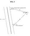
- FIG. 3illustrates an exemplary site which is to be surveyed using the SDID 210 to collect data of a field site.
- the site surveywill be described below in conjunction with the flow charts illustrated in FIGS. 4A and 4B .
- the WMS 220receives a job request at step S 410 .
- the job requestmay be generated at the WMS 220 , or it may be generated at some other location and transmitted to the WMS 220 .
- the job requestincludes, for example, a project site address and preliminary instructions.
- the preliminary instructionsmay include a description of the project site, including the type of site (e.g., building site), the nature of work that should be performed on or with respect to the site, and any other relevant instructions necessary to communicate the information to complete the work on the project site.
- the requestmay, for example, be generated by an user on the SDID 210 and downloaded to the WMS 220 . Alternatively, the request may have been generated directly on the WMS 220 , or it may have been generated remotely and communicated to the WMS 220 by email, facsimile, instant messaging commands or any other known communication technology.
- the WMS 220Upon receiving the job request, the WMS 220 creates a project folder at step S 415 .
- the project folderprovides an easily retrievable location for accessing and managing necessary data and programs for accomplishing a given project. WMS 220 may also generate links to other data and programs that will likely interface with the newly created folder. For example, once the address is provided, WMS 220 may establish communication, e.g., over the Internet, with vendors to retrieve current inventory and pricing information that is typically needed for the project for which it has received instructions at step S 410 .
- the WMS 220uses the smart technology discussed above, builds project data into the project folder.
- the WMS 220may use the address it received at step S 410 to retrieve survey plats for the address location, as well as survey plats for adjoining locations.
- WMS 220may retrieve the plats from the database DB 230 , which in this case may be a public records database managed by the County, a vendor that is able to provide the necessary plats, an historical internal database of previous projects, or the like. WMS 220 then retrieves any data associated with the address it finds and loads the information into a newly created project file.
- WMS 220may retrieve data it has located regarding pre-installed telephone poles, electrical power lines, fences, underground fiber optic lines, distribution boxes, hazardous conditions, etc.
- WMS 220loads all of the relevant data for the project into the project file.
- the WMS 220uses the up-to-date data, proceeds to process the information to generate a draft work print.
- the exemplary draft work printwill include a topographical survey plat with locations and annotations overlaid onto the plat.
- the annotationsmay include descriptions and locations of various known site features, such as the above mentioned telephone poles, electrical power lines, fences, hazards, etc.
- the survey platmay be a two-dimensional plat with appropriate demarcations. However, where topographical information is critical, a three-dimensional (or greater) plat may be used in order to convey a more accurate, real-world plat to the field engineer.
- the SDID 210is coupled to the WMS 220 to upload the draft work print. This may be accomplished by implementing a dedicated SDID cradle (not shown) and locating it on premises with WMS 220 .
- the dedicated cradlewould provide an interface whereby the information on the SDID 210 would be synchronized with corresponding information on the WMS 220 in order to ensure that each system has the most up to date information. Any known synchronization methodology may be used, including time stamp comparison, version control, or any other scheme that works within the spirit and scope of the disclosure.
- SDID 210may upload the information from the WMS 220 from a remote location over a satellite link, telephone line, Internet connection, radio frequency connection, optical signal connection, or any other transmission medium that can facilitate transmission of digital or analog information between two locations.
- any or all of steps S 410 through S 435may be performed on the SDID 210 instead of the WMS 220 without departing from the spirit and scope of the present disclosure. Further, these steps may have been performed on another WMS device and made available to the WMS and/or the SDID 210 in real time or through a data store.
- the SDID 210is taken to a project site to carry out the necessary survey steps, as illustrated in FIG. 4B , for example.
- the usermay physically go to the project site and retrieve the draft work print on the SDID 210 .
- the usermay choose to send a robot to gather the necessary information.
- the robotmay be a land, water, or air-traversing machine, which may be equipped with artificial intelligence and may be configured to receive instructions from the field engineer.
- FIG. 3shows an example of a draft work print of the type retrieved at step S 450 .
- the exemplary draft work print shown in FIG. 3includes a roadway 310 and a preloaded geographic point P 1 , with a notation, e.g., “Telephone Pole, Installed Apr. 5, 1976.”
- the userthen, for example, walks to point P 2 .
- the usermay select the point (using the SDID 210 , as described below) as a geographic point.
- the SDID 210automatically reads the geographic data from the GPS receiver, for example, corresponding to the geographic location of P 2 .
- the SDID 210stores the geographic location data in association with P 2 , including longitude, latitude and altitude.
- a GPS devicewhich may be used in conjunction with the present disclosure is the MobileMapperTM CE, which provides for real-time GPS performance, integrated BluetoothTM wireless technology, field-replaceable SD card memory and Li-ion battery, alphanumeric keypad, touch-screen, all enclosed in a waterproof casing.
- the SDID 210may be configured to include an auto-check function that allows the user to obtain updates for selected geographic points. For example, the desired location or intended purpose of P 2 may have changed.
- the SDID 210may check for updates by performing a data check on data stored in the SDID 210 . However, the update check may be performed by sending a call signal to the WMS 220 to check for status updates, and if any are found, to upload the updated information to SDID 210 by any one of the communication medium described above.
- the SDID 210overlays the input geographic positions and location specific notes on to the draft work print so that the user may see the progress as he or she proceeds to survey the project site.
- the useris queried as to whether he or she wishes to select another geographic point, enter additional notes or other information, or finalize the draft work print. In the example of FIG. 3 , the user elects to proceed from P 2 (e.g., where the draft work print indicates a request for a “New Pole” to be installed) to point P 3 .
- P 2e.g., where the draft work print indicates a request for a “New Pole” to be installed
- the userselects the point as a geographic point at step S 455 and receives the corresponding location data, and enters a note, e.g., “Pole to be Removed,” at step S 460 .
- the SDID 210may display respective distances D 1 , D 2 , D 3 and D 4 for the distances from the roadway 310 to pole P 1 , from pole P 1 to pole P 2 , from pole P 2 to pole P 3 , and from pole P 3 to roadway 310 , respectively.
- step S 470the user elects to finalize and the subroutine of FIG. 4B ends.
- the SDID 210is again connected to the WMS 220 , either by hard wire or wireless, and the finalized draft work print is downloaded to the WMS 220 at step S 440 .
- the WMS 220generates a final work print and a work order based on the down-loaded information.
- the final work printwill be a final version of the draft work print, including all site specific data collected by the user, that has been approved by the field engineer or any other necessary party.
- the actual work print and the work ordermay be stored (and a backup copy may be archived) by the WMS 220 into, for example, the database DB 230 or in a local memory at step S 446 .
- the work ordermay be forwarded to an entity charged with physically completing the project.
- the work ordermay include, for example: a project identification; a project location; specific material necessary for the project; specific tasks that must performed at the project; an estimation of the time necessary to complete each of the tasks; and/or a cost associated with each of the tasks and the specific material to be used.
- the work ordermay also include detailed information, such as: cable type; cable size; cable length; terminal type; terminal count; terminal size; splice points; closures; poles and the like, which are necessary to carry out a project to completion.
- the work ordermay also include a job budget based on pricing and inventory information, job management time codes for specific tasks enumerated in the work order, and any other information that affects the overall project budget.
- the WMS 220in generating the job budget, will access the most up to date cost and inventory data for supplies from vendors as discussed above. The WMS 220 will then compile and generate the work order with the most current information, including a job budget. If it is determined that inventories are insufficient to support the needs of a specific work order, the WMS 220 can send requests for vendors to replenish stock, to stock certain new items, or any other similar request. In an embodiment, the WMS 220 automatically generates the information detailed in the work order, by accessing various databases and calculating cost, budgets and the like.
- the work orderis forwarded to a general contractor that has been delegated the responsibility of overseeing construction of the project in accordance with the work order and actual work print.
- the general contractorthen dispatches a crew to the project site to complete the project in accordance with the work order and actual work print.
- the present disclosureis not limited to surveying and documenting potential work sites, and that the charged entity may be any entity assigned the task of completing the project in accordance with the work order and actual work print without departing from the spirit and scope of the disclosure.
- the disclosuremay be equally used in any environment requiring determination of specific geographic locations and association of various notes readily associated with those locations, including relationships with other specific geographic locations.
- the disclosed system and processmay be used with respect to construction sites, retail or wholesale stores, real estate, hydrographic survey sites, offshore and land core drilling sites, dredge sites, law firms, and the like.
- the disclosuremay be used by law firms in order to inventory files that are spread across the law firm building(s); by libraries to inventory books and their respective locations; by census poll takers to collect census data; by freight and shipping entities to track specific container inventories and locations.
- the disclosuremay likewise be used in the retail and wholesale industries to manage inventory.
- a store clerkmay use the SDID 210 to inventory stock that is located on premises in a store, including its specific location and quantity, and any notes that the clerk may decide to include with respect to the location and items.
- the SDID 210may be fitted with the scanning device module discussed above to enable the clerk to scan universal product code (UPC) labels printed on the items.
- UPCuniversal product code
- the exemplary SDID 210includes a display 501 , an embedded digital compass (not shown), QUICK keys 502 - 507 , numeric keypad 508 , RANGE key 509 , CAMERA key 510 , FUNCTION keys (F 1 -F 5 ) 511 , MAIN MENU key 512 , BEGIN/END TRACKING key 513 , directional keys 514 , and pivotal member 515 .
- the exemplary SDID 210may be enclosed in ambient-proof casing that is water proof, drop resistant and temperature resistant.
- FIG. 5is an exemplary embodiment of the SDID 210 , but the skilled artisan will readily recognize that the disclosure is not limiting to the exemplary embodiment, modifications and/or replacements may be made without departing from the spirit and scope of the disclosure.
- the MAIN MENU key 512when activated, triggers the SDID 210 to display a main menu on display 501 .
- the useris then able to select a wide variety of functions from displayed items, including configuration and control of various supplemental devices.
- the useris also able to control most of the SDID 210 processes by initiating the MAIN MENU and maneuvering through its contents using the directional keys 514 and/or the pivotal member 515 .
- the directional keys 514 and pivotal member 515are provided to enable the user of the SDID 210 to manipulate a cursor on the display 501 through a graphic user interface (GUI) (not shown). Keys 514 and 515 provide a user-friendly interface, enabling the user to mimic the functionality of a multidimensional computer mouse.
- the directional keys 514for example, allow the user to manipulate a cursor on a draft work print displayed on the display 501 to modify objects and their locations.
- the pivotal member 515allows for further manipulation of the same cursor, or an additional cursor for multidimensional manipulation of displayed data on display 501 .
- the pivotal memberin an exemplary embodiment, is a pivotal joystick that operates in 360 degrees, with a push down to select feature.
- any functionality enabling manipulation of a cursor on the display 501such as a touch pad, may be included on the SDID 210 without departing from the spirit and scope of the present disclosure.
- the useris able to record a continuous line of geographic points by depressing the button BEGIN/END TRACKING 513 once to start tracking and a second time to stop the tracking.
- This function keyallows the SDID 210 to record a line of geographical points that a user traverses while moving from an initial point (when the key 513 was depressed a first time) to an ending point (when the key 513 was depressed a second time) using GPS data.
- This function keyis practical in enabling the user to record fence lines or power lines, for example, on a draft work print.
- Selection of the CAMERA key 510will activate digital camera functionality (not shown), which may be integral to the SDID 210 or connectable through one of the interface ports of the SDID 210 .
- the display 501Upon activation of this key, the display 501 will display the optical field that may be captured by the digital camera. Control of the digital camera is facilitated through touch screen soft keys that are displayed to the user along the lower most region of the display 501 (not shown), and/or through pivotal member 515 .
- the RANGE key 509enables the user to select geographic points from a distance using an optical range finder (i.e., when the SDID 210 is equipped with a supplemental range finder module) and the digital camera discussed above, without having to physically stand at the point which is to be selected as a geographic point.
- activation of RANGE key 509activates the supplemental range finder module and the internal digital camera to display a field of view on to the display 501 , as well as obtain measured distances to an object selected on the display 501 and display such distances.
- the objectmay be targeted by overlaying a cross-hair or cursor on the displayed image field, enabling the user to select an object using either of keys 514 or 515 .
- the useris able to manipulate the cross-hair or cursor to overlay a selected target object and to select it as a geographic point, along with its positional information.
- the positional informationis automatically determined using the known geographic position where the user is standing (e.g., through receipt of GPS information) and the range to the target object. This feature allows the user to obtain geographic points that may otherwise be practically unattainable.
- the range findermay be used to target the object without use of the camera device.
- Function keys F 1 to F 5are programmable keys that are programmable through manipulation of the MAIN MENU key 512 and/or an ADD TASK key 507 .
- the function keys F 1 to F 5may thus be programmed to serve as extra QUICK keys, in addition to QUICK keys 502 - 507 , or they may be programmed to serve as activation keys for supplemental devices that may be later coupled to the SDID 210 .
- the key F 1may be programmed to activate a simulation module or a computer based training module, which can be used to train new users on the use of the SDID unit and/or surveying methodology.
- FIG. 6shows an exemplary embodiment of the QUICK key features. Selection of any one of the QUICK keys 502 to 506 will cause the SDID 210 , at step S 605 , to set the QUICK key mode to the mode selected. The SDID 210 is then ready for the first selection of a geographic point (i.e., a GP point). At a first selection of a geographic point, as described above, the SDID 210 determines that a selection has been made and proceeds to record the corresponding coordinates at step S 610 . At step S 620 , the SDID then prompts the user to enter notes for the corresponding geographic point. The default input data entry mode is set to the QUICK key mode, described later in greater detail with respect to FIGS. 7 and 8 .
- the SDID 210also checks for updated information for the corresponding geographic point; and if any is found to exist, the SDID 210 displays the new information at step S 625 before overlaying the information onto the draft work print at step S 626 . Then, at step S 630 , the user is prompted as to whether data entry has been completed. If it has, then the routine ends, otherwise it loops to step S 610 to receive geographic position information for another point.
- the SDID 210when the user activates the TEXT key 502 , the QUICK default entry mode is overridden and the SDID 210 proceeds to the data entry mode selection process shown in FIG. 7 .
- activation of the TEXT key 502will open up a scroll menu on display 501 offering the options of text entry, numeric entry or quick entry at step S 730 .
- the SDID 210Upon selecting one of the input modes at step S 730 , the SDID 210 will proceed to the corresponding one of steps S 720 , S 740 , or S 750 .
- the SDID 210When the text mode has been selected at step S 730 , the SDID 210 will set the input mode to text at step S 720 .
- the SDID 210will enable numeric entry at step S 740 .
- the SDID 210will enable quick entry at step S 750 , which may display additional predetermined or preprogrammed quick entry options for which no QUICK key presently exists.
- the TEXT modeenables a user, e.g., to type in information using an attachable keypad or an integral iTAP feature.
- a hierarchical listing of termsmay appear in display 501 as illustrated in FIG. 8 .
- the usermay maneuver through different commonly used terms by using keys 514 and/or 515 , which he or she may want to include in the notes associated with a particular geographic position.
- the commonly used terms, displayed in FIG. 8are hierarchically displayed in multi-tiers. For example, SIGN, HYDRANT and MAILBOX are single tiered. Selection of any of these three terms, for example, will only insert the term into the draft work print at the corresponding geographic point.
- the descriptors CULVERT, HAZARD and CAUTIONare predefined as two-tiered and FENCE and DRIVE are predefined as three-tiered.
- a selection of CULVERTwill open up the options of AROUND or BORE for selection, describing two common types of culverts that may be present on site.
- a selection of HAZARDwill open up the options of ELECTRIC FENCE or MEAN DOG for selection.
- a selection of CAUTIONwill open up the options of GAS, WATER, SEWER, COSTLY LANDSCAPE or VOLTAGE for selection.
- a selection of FENCEwill open up the options of CORNER, PERPENDICULAR OR PARALLEL, with a further selection of PARALLEL, for example, opening up further options of BEGIN or END for selection. This then prompts the user to enter geographic position data corresponding to the beginning or the end of a fence line.
- a selection of DRIVEwill open up the options of GRAVEL or PAVED, likewise followed by a further selection option of BEGIN or END.
- the quick entrymay also include, for example, the “iTap” technology used by MOTOROLATM for quick entry of commonly used characters and words. Further, the quick entry may also include preprogrammed lines of text that the user would expect to enter on site, allowing the user to avoid excessive text entry for predictable items.
- step S 605 of FIG. 6activation of the STATION MARK key 503 will set the Mode to STATION MARK at step S 605 of FIG. 6 .
- the SDID 210prompts the user to record the GPS location data associated with the selected location (e.g., the location at which the user is presently standing or a remote location identified through use of the RANGE key 509 ) as a GP point, i.e., at step S 610 .
- step S 620the SDID 210 prompts the user for data entry notes.
- quick entry modediscussed above, is set by default.
- the menu of FIG. 8for example is automatically displayed, showing common terms in a hierarchical format on display 501 .
- the usermay then maneuver through the displayed menu, e.g., using keys 514 and/or 515 , to select the desired notes.
- the SDID 210also displays new information at step S 625 and overlays the information collected at steps S 610 , S 620 and S 625 onto the draft work print at step S 626 .
- the SDID 210Upon completing data entry for the respective GP point, the SDID 210 will prompt the user at step S 630 whether the survey project is complete.
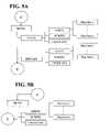
- Activation of the EXISTING PLANT key 504 or PLACE NEW PLANT key 505will cause the SDID 210 to go through the same steps as described above with respect to selection of the STATION MARKER key 503 , except that instead of displaying the quick entry menu illustrated in FIG. 8 at the data entry step S 630 in FIG. 6 , the SDID will display the quick entry menus shown in FIGS. 9A and 9B , respectively, at data entry step S 630 .
- activation of key 504will present the user with menu selection options TRACK and REPLACE on display 501 , which may refer to some element of the physical plant, such as a power line or cable.
- TRACKmenu selection options
- REPLACEsome element of the physical plant
- the userUpon selecting TRACK, for example, the user will be presented with three further selection options, i.e., AERIAL, BURIED, and UNDERGROUND, the selection of which indicates the status (or anticipated status) of the element.
- the AERIAL optioncorresponds to anything that is aerial by nature, including cables, power lines, branches, etc.
- the BURIED optioncorresponds to anything that is buried in the ground and that is in direct contact with the environment (e.g., soil, moisture, etc.).
- the UNDERGROUND optionon the other hand, corresponds to anything that is underground and protected from the environment.
- the userUpon selecting one of the three further selection options, the user will be given a predefined number of options for PLANT types for any one of the three further selection options. For example, the user may be given an n number of plant options (where n is a positive integer that represents the number of predetermined plant options), such as cable, cable size, cable gauge, etc.
- the TRACK selection optionautomatically places the SDID 210 _into a multi-GP point record mode so that the SDID 210 will track a geographical line that tracks and records the user's movement from initiation of the TRACK mode to its termination, similar to the functionality described above with respect to the BEGIN/END TRACKING key 513 . It performs the tracking operation by regularly recording GPS positions at predetermined periods of time that are sufficient to generate an accurate representation of the item tracked (e.g., a power line) and its relationship to the project plat.
- the REPLACE selection optionautomatically places the SDID 210 into a “replacement” mode.
- the usermay select whether the structure to be replaced is AERIAL, BURIED, or UNDERGROUND, as discussed above. If the user chooses AERIAL, for example, then the user may select the PLANT ITEM that needs to be replaced (e.g., a telephone pole).
- the SDID 210then automatically annotates the GP point with a notation that the telephone pole located at that GP point needs to be replaced.
- FIG. 9Bdepicts activation of the PLACE NEW PLANT key 505 , which presents the user with menu selection options, such as AERIAL, BURIED, and UNDERGROUND, as described above.
- menu selection optionssuch as AERIAL, BURIED, and UNDERGROUND, as described above.
- Activation of key 505enables the user to automatically record the GP position at which a new plant is to be placed, as well as enable the user to identify the specific plant item using the QUICK mode entry option. Selection of one of these three options will then present the user with a plurality of predetermined PLANT ITEM selection options, e.g., cable, cable size, cable gauge, etc.
- Activation of the TRANSITION ENVIRONMENT key 506 in FIG. 5will trigger recall and display of exemplary, predetermined, commonly used descriptors as illustrated in FIG. 10 , for example.
- activation of key 506will prompt the user to select, for example, one of six predefined transitions.
- the usermay select any one of the following transitions: UNDERGROUND to BURIED; UNDERGROUND to AERIAL; BURIED to UNDERGROUND; AERIAL to UNDERGROUND; BURIED to AERIAL; or AERIAL to BURIED.
- a selection of any one of the six options, for example,will cause the SDID 210 to further display the options of generating a split (i.e., GENERATE SPLIT) or replacing a stub (i.e., REPLACE STUB) at the respective GP point. If the user selects the option REPLACE STUB, the SDID 210 presents the further options of selecting a manufactured stub (i.e., MANUFACTURED) or a cable stub (i.e., CABLE). Selection of either MANUFACTURED or CABLE, will cause the SDID 210 to present a series of predetermined sizes, SIZE 1 to SIZE n, where n is a positive integer.
- the SDID 210Upon selecting one of the SIZE options, the user is presented with a predetermined number m of types (m is a positive integer that represents the number of predetermined sizes, where the size may be any real value), TYPE 1 to TYPE m. Finally, upon selecting one of the TYPE options, the SDID 210 generates a split (GENERATE SPLIT) at the respective GP point and annotates the draft work print accordingly.
- mis a positive integer that represents the number of predetermined sizes, where the size may be any real value
- Selection of the ADD TASK key 507will display on the display 501 a plurality of predefined, additional functions that the user may wish to add to any of the above tasks associated with the above described functions.
- Common exemplary tasks that may be includedare: PLOWING; TRENCH MECHANICAL; TRENCH BY HAND; TRENCH MISCELLANEOUS; SPLICE PIT; TRENCH EXPOSE LOWER CABLE; BORING UNDER ROAD; RESTORATION OF PROPERTY; HAND HOLE/MAN HOLE; RODING OF DUCTS; UNDERGROUND REMOVAL; MISCELLANEOUS UNDERGROUND; BUILDING/STRUCTURE; AERIAL PLACE/REMOVAL; AERIAL MISCELLANEOUS; POLES; POLES MISCELLANEOUS; ANCHORS; TRANSFER OF ARIAL PLANT; TREE TRIM; BURIED SERVICE WIRE WORK; LINEMEN HOURLY; CREW RATE; EQUIPMENT; and SPLICING
- the useris able to receive specific, geographic location data, collected on-site by a GPS receiver or the like, and efficiently input contemporaneous notes and other associated data.
- the usermay build a previously generated draft plan, such as a preliminary work print, and subsequently download the collected data and observations for automatic production of a final work order and/or final work print.
- the exemplary SDID 210 of FIG. 5depicts the various functions and capabilities to maximize efficiency for the user.
- inventions of the disclosuremay be referred to herein, individually and/or collectively, by the term “invention” merely for convenience and without intending to voluntarily limit the scope of this application to any particular invention or inventive concept.
- inventionsmerely for convenience and without intending to voluntarily limit the scope of this application to any particular invention or inventive concept.
- specific embodimentshave been illustrated and described herein, it should be appreciated that any subsequent arrangement designed to achieve the same or similar purpose may be substituted for the specific embodiments shown.
- This disclosureis intended to cover any and all subsequent adaptations or variations of various embodiments. Combinations of the above embodiments, and other embodiments not specifically described herein, will be apparent to those of skill in the art upon reviewing the description.
Landscapes
- Engineering & Computer Science (AREA)
- Databases & Information Systems (AREA)
- Remote Sensing (AREA)
- Physics & Mathematics (AREA)
- General Physics & Mathematics (AREA)
- Theoretical Computer Science (AREA)
- Data Mining & Analysis (AREA)
- General Engineering & Computer Science (AREA)
- Radar, Positioning & Navigation (AREA)
- Management, Administration, Business Operations System, And Electronic Commerce (AREA)
- Position Fixing By Use Of Radio Waves (AREA)
Abstract
Description
Claims (20)
Priority Applications (2)
| Application Number | Priority Date | Filing Date | Title |
|---|---|---|---|
| US11/449,825US7664530B2 (en) | 2006-06-09 | 2006-06-09 | Method and system for automated planning using geographical data |
| US12/646,209US7904114B2 (en) | 2006-06-09 | 2009-12-23 | Method and system for automated planning using geographical data |
Applications Claiming Priority (1)
| Application Number | Priority Date | Filing Date | Title |
|---|---|---|---|
| US11/449,825US7664530B2 (en) | 2006-06-09 | 2006-06-09 | Method and system for automated planning using geographical data |
Related Child Applications (1)
| Application Number | Title | Priority Date | Filing Date |
|---|---|---|---|
| US12/646,209ContinuationUS7904114B2 (en) | 2006-06-09 | 2009-12-23 | Method and system for automated planning using geographical data |
Publications (2)
| Publication Number | Publication Date |
|---|---|
| US20070288159A1 US20070288159A1 (en) | 2007-12-13 |
| US7664530B2true US7664530B2 (en) | 2010-02-16 |
Family
ID=38822934
Family Applications (2)
| Application Number | Title | Priority Date | Filing Date |
|---|---|---|---|
| US11/449,825Active2028-01-17US7664530B2 (en) | 2006-06-09 | 2006-06-09 | Method and system for automated planning using geographical data |
| US12/646,209ActiveUS7904114B2 (en) | 2006-06-09 | 2009-12-23 | Method and system for automated planning using geographical data |
Family Applications After (1)
| Application Number | Title | Priority Date | Filing Date |
|---|---|---|---|
| US12/646,209ActiveUS7904114B2 (en) | 2006-06-09 | 2009-12-23 | Method and system for automated planning using geographical data |
Country Status (1)
| Country | Link |
|---|---|
| US (2) | US7664530B2 (en) |
Cited By (41)
| Publication number | Priority date | Publication date | Assignee | Title |
|---|---|---|---|---|
| US20090013928A1 (en)* | 2007-04-04 | 2009-01-15 | Certusview Technologies, Llc | Marking system and method |
| US20090076726A1 (en)* | 2007-07-25 | 2009-03-19 | Gemignani Jr Joseph A | Transmission line data acquisition system |
| US20090202110A1 (en)* | 2008-02-12 | 2009-08-13 | Steven Nielsen | Electronic manifest of underground facility locate marks |
| US20090204238A1 (en)* | 2007-03-13 | 2009-08-13 | Nielsen Steven E | Electronically controlled marking apparatus and methods |
| US20090201178A1 (en)* | 2007-03-13 | 2009-08-13 | Nielsen Steven E | Methods for evaluating operation of marking apparatus |
| US20100088031A1 (en)* | 2008-10-02 | 2010-04-08 | Certusview Technologies, Llc | Methods and apparatus for generating an electronic record of environmental landmarks based on marking device actuations |
| US20100085185A1 (en)* | 2008-10-02 | 2010-04-08 | Certusview Technologies, Llc | Methods and apparatus for generating electronic records of locate operations |
| US20100084532A1 (en)* | 2008-10-02 | 2010-04-08 | Certusview Technologies, Llc | Marking device docking stations having mechanical docking and methods of using same |
| US20100085376A1 (en)* | 2008-10-02 | 2010-04-08 | Certusview Technologies, Llc | Methods and apparatus for displaying an electronic rendering of a marking operation based on an electronic record of marking information |
| US20100088164A1 (en)* | 2008-10-02 | 2010-04-08 | Certusview Technologies, Llc | Methods and apparatus for analyzing locate and marking operations with respect to facilities maps |
| US20100188215A1 (en)* | 2008-10-02 | 2010-07-29 | Certusview Technologies, Llc | Methods and apparatus for generating alerts on a marking device, based on comparing electronic marking information to facilities map information and/or other image information |
| US20100189312A1 (en)* | 2008-10-02 | 2010-07-29 | Certusview Technologies, Llc | Methods and apparatus for overlaying electronic locate information on facilities map information and/or other image information displayed on a locate device |
| US20100188407A1 (en)* | 2008-10-02 | 2010-07-29 | Certusview Technologies, Llc | Methods and apparatus for displaying and processing facilities map information and/or other image information on a marking device |
| US20100189887A1 (en)* | 2008-10-02 | 2010-07-29 | Certusview Technologies, Llc | Marking apparatus having enhanced features for underground facility marking operations, and associated methods and systems |
| US20100188088A1 (en)* | 2008-10-02 | 2010-07-29 | Certusview Technologies, Llc | Methods and apparatus for displaying and processing facilities map information and/or other image information on a locate device |
| US20100188245A1 (en)* | 2008-10-02 | 2010-07-29 | Certusview Technologies, Llc | Locate apparatus having enhanced features for underground facility locate operations, and associated methods and systems |
| US20100198663A1 (en)* | 2008-10-02 | 2010-08-05 | Certusview Technologies, Llc | Methods and apparatus for overlaying electronic marking information on facilities map information and/or other image information displayed on a marking device |
| US20100317407A1 (en)* | 2009-06-16 | 2010-12-16 | Bran Ferren | Secondary display device |
| US20100325604A1 (en)* | 2009-06-22 | 2010-12-23 | Embarq Holdings Company, Llc | System and method for performing cost estimation in a service provider environment |
| US20110010093A1 (en)* | 2009-07-09 | 2011-01-13 | Palo Alto Research Center Incorporated | Method for encouraging location and activity labeling |
| US20110007076A1 (en)* | 2009-07-07 | 2011-01-13 | Certusview Technologies, Llc | Methods, apparatus and systems for generating searchable electronic records of underground facility locate and/or marking operations |
| US20110060549A1 (en)* | 2009-08-20 | 2011-03-10 | Certusview Technologies, Llc | Methods and apparatus for assessing marking operations based on acceleration information |
| US20110117272A1 (en)* | 2009-08-20 | 2011-05-19 | Certusview Technologies, Llc | Marking device with transmitter for triangulating location during locate operations |
| US20110131081A1 (en)* | 2009-02-10 | 2011-06-02 | Certusview Technologies, Llc | Methods, apparatus, and systems for providing an enhanced positive response in underground facility locate and marking operations |
| US20110191058A1 (en)* | 2009-08-11 | 2011-08-04 | Certusview Technologies, Llc | Locating equipment communicatively coupled to or equipped with a mobile/portable device |
| US20110236588A1 (en)* | 2009-12-07 | 2011-09-29 | CertusView Techonologies, LLC | Methods, apparatus, and systems for facilitating compliance with marking specifications for dispensing marking material |
| US8413039B2 (en) | 2011-02-23 | 2013-04-02 | Io Services, Inc. | Computer-implemented system and method for conducting field inspections and generating reports |
| US8473209B2 (en) | 2007-03-13 | 2013-06-25 | Certusview Technologies, Llc | Marking apparatus and marking methods using marking dispenser with machine-readable ID mechanism |
| US20130162431A1 (en)* | 2008-10-02 | 2013-06-27 | Steven Nielsen | Methods and apparatus for generating alerts on a locate device, based on comparing electronic locate information to facilities map information and/or other image information |
| US8532341B2 (en)* | 2008-02-12 | 2013-09-10 | Certusview Technologies, Llc | Electronically documenting locate operations for underground utilities |
| US20130241698A1 (en)* | 2012-03-14 | 2013-09-19 | Trimble Navigation Ltd | Application of low power rfid tags to data collection devices and receivers/instruments to speed setup |
| US8861795B2 (en) | 2008-03-18 | 2014-10-14 | Certusview Technologies, Llc | Virtual white lines for delimiting planned excavation sites |
| US8902251B2 (en) | 2009-02-10 | 2014-12-02 | Certusview Technologies, Llc | Methods, apparatus and systems for generating limited access files for searchable electronic records of underground facility locate and/or marking operations |
| US8977558B2 (en) | 2010-08-11 | 2015-03-10 | Certusview Technologies, Llc | Methods, apparatus and systems for facilitating generation and assessment of engineering plans |
| US8990100B2 (en) | 2008-10-02 | 2015-03-24 | Certusview Technologies, Llc | Methods and apparatus for analyzing locate and marking operations with respect to environmental landmarks |
| US9004004B2 (en) | 2008-07-10 | 2015-04-14 | Certusview Technologies, Llc | Optical sensing methods and apparatus for detecting a color of a marking substance |
| US9097522B2 (en) | 2009-08-20 | 2015-08-04 | Certusview Technologies, Llc | Methods and marking devices with mechanisms for indicating and/or detecting marking material color |
| US9265458B2 (en) | 2012-12-04 | 2016-02-23 | Sync-Think, Inc. | Application of smooth pursuit cognitive testing paradigms to clinical drug development |
| US9280269B2 (en) | 2008-02-12 | 2016-03-08 | Certusview Technologies, Llc | Electronic manifest of underground facility locate marks |
| US9380976B2 (en) | 2013-03-11 | 2016-07-05 | Sync-Think, Inc. | Optical neuroinformatics |
| US9904450B2 (en) | 2014-12-19 | 2018-02-27 | At&T Intellectual Property I, L.P. | System and method for creating and sharing plans through multimodal dialog |
Families Citing this family (22)
| Publication number | Priority date | Publication date | Assignee | Title |
|---|---|---|---|---|
| TWI330325B (en)* | 2007-03-14 | 2010-09-11 | Mitac Int Corp | Regional message reminder apparatus and method, intergration message reminder apparatus and method |
| US9659268B2 (en) | 2008-02-12 | 2017-05-23 | CertusVies Technologies, LLC | Ticket approval system for and method of performing quality control in field service applications |
| US20090327024A1 (en)* | 2008-06-27 | 2009-12-31 | Certusview Technologies, Llc | Methods and apparatus for quality assessment of a field service operation |
| US9208464B2 (en) | 2008-10-02 | 2015-12-08 | Certusview Technologies, Llc | Methods and apparatus for analyzing locate and marking operations with respect to historical information |
| WO2010039262A2 (en)* | 2008-10-02 | 2010-04-08 | Certusview Technologies, Llc | Methods and apparatus for analyzing locate and marking operations with respect to environmental landmarks |
| US8620726B2 (en) | 2008-10-02 | 2013-12-31 | Certusview Technologies, Llc | Methods and apparatus for analyzing locate and marking operations by comparing locate information and marking information |
| CA2691780C (en) | 2009-02-11 | 2015-09-22 | Certusview Technologies, Llc | Management system, and associated methods and apparatus, for providing automatic assesment of a locate operation |
| US8489545B2 (en)* | 2009-03-18 | 2013-07-16 | Norman Ritchie | System and method for creating and maintaining pre-task planning documents |
| US8918898B2 (en)* | 2010-07-30 | 2014-12-23 | Certusview Technologies, Llc | Methods, apparatus and systems for onsite linking to location-specific electronic records of locate operations |
| US9210049B2 (en) | 2011-11-22 | 2015-12-08 | Adc Telecommunications, Inc. | Intelligent infrastructure management user device |
| WO2013192533A2 (en)* | 2012-06-22 | 2013-12-27 | Google, Inc. | Contextual traffic or transit alerts |
| CN104396284B (en) | 2012-06-22 | 2016-09-07 | 谷歌公司 | Present information specific to the current location or time |
| US20140089835A1 (en)* | 2012-09-21 | 2014-03-27 | EVCO Plastics | Application for Core Drilling |
| US20140278660A1 (en)* | 2013-03-15 | 2014-09-18 | Profit Strategies, Inc. | Methods for generating a work-order in real time and devices thereof |
| US9183222B2 (en) | 2014-01-28 | 2015-11-10 | Gas Technology Institute | Mapping and asset lifecycle tracking system |
| US9503516B2 (en) | 2014-08-06 | 2016-11-22 | Google Technology Holdings LLC | Context-based contact notification |
| EP3054404A1 (en)* | 2015-02-04 | 2016-08-10 | Hexagon Technology Center GmbH | Work information modelling |
| US9870196B2 (en)* | 2015-05-27 | 2018-01-16 | Google Llc | Selective aborting of online processing of voice inputs in a voice-enabled electronic device |
| US10083697B2 (en)* | 2015-05-27 | 2018-09-25 | Google Llc | Local persisting of data for selectively offline capable voice action in a voice-enabled electronic device |
| US9966073B2 (en) | 2015-05-27 | 2018-05-08 | Google Llc | Context-sensitive dynamic update of voice to text model in a voice-enabled electronic device |
| TR201619806A2 (en)* | 2016-12-28 | 2018-07-23 | Turkcell Teknoloji Arastirma Ve Gelistirme Anonim Sirketi | AN INTERNET INFRASTRUCTURE COST CALCULATION SYSTEM |
| US11507902B2 (en)* | 2020-02-10 | 2022-11-22 | Caterpillar Paving Products Inc. | System and method for vehicle project tracking |
Citations (28)
| Publication number | Priority date | Publication date | Assignee | Title |
|---|---|---|---|---|
| US5023900A (en)* | 1989-12-07 | 1991-06-11 | Tayloe Daniel R | Cellular radiotelephone diagnostic system |
| US5404661A (en)* | 1994-05-10 | 1995-04-11 | Caterpillar Inc. | Method and apparatus for determining the location of a work implement |
| US5606604A (en)* | 1993-12-13 | 1997-02-25 | Lucent Technologies Inc. | System and method for preventing fraud upon PBX through a remote maintenance or administration port |
| US5809415A (en)* | 1995-12-11 | 1998-09-15 | Unwired Planet, Inc. | Method and architecture for an interactive two-way data communication network |
| US5842210A (en)* | 1996-10-30 | 1998-11-24 | Motorola, Inc. | Method and apparatus for selectively retrieving data from a database in a data communication system |
| US5990932A (en)* | 1997-12-22 | 1999-11-23 | Northern Telecom, Limited | Collaborative shared space |
| US6083353A (en)* | 1996-09-06 | 2000-07-04 | University Of Florida | Handheld portable digital geographic data manager |
| US6336035B1 (en)* | 1998-11-19 | 2002-01-01 | Nortel Networks Limited | Tools for wireless network planning |
| US20020123338A1 (en)* | 2000-12-29 | 2002-09-05 | Iyer Gopal N. | Method for reverse path mapping in a wireless network using Xtel and lucent telecommunications equipment |
| US20020136374A1 (en) | 2001-01-17 | 2002-09-26 | Sbc Technology Resources, Inc. | Dialing plan service including outgoing call screening, remote tie-line routing, call data reporting and billing |
| US6662193B1 (en)* | 2000-06-02 | 2003-12-09 | Cg4 Solutions, Inc. | Methods and systems for manipulating a database through portable data entry devices |
| US6751553B2 (en) | 2000-06-14 | 2004-06-15 | Vermeer Manufacturing Company | Utility mapping and data distribution system and method |
| US20040128313A1 (en) | 2002-12-13 | 2004-07-01 | Whyman Wynne J. | Database system for outdoor property management and maintenance |
| US6771956B1 (en)* | 2000-11-08 | 2004-08-03 | Bellsouth Intellectual Property Corporation | Real time call data analysis and display |
| US6792269B2 (en)* | 2000-12-22 | 2004-09-14 | Bellsouth Intellectual Property Corporation | System, method and apparatus for tracking deployment of cellular telephone network sites |
| US20040192329A1 (en)* | 2000-06-27 | 2004-09-30 | Barbosa Frank A. | Field assessments using handheld data management devices |
| US6826385B2 (en)* | 2002-02-22 | 2004-11-30 | Nokia Corporation | Method and system for distributing geographical addresses across the surface of the earth |
| US20050186915A1 (en)* | 2002-08-08 | 2005-08-25 | Williams Douglas M. | Interactive graphical user interface for an internet site providing data related to radio frequency emmitters |
| US6985941B2 (en)* | 1997-11-20 | 2006-01-10 | Xacct Technologies, Ltd. | Database management and recovery in a network-based filtering and aggregating platform |
| US7003284B2 (en)* | 1995-12-11 | 2006-02-21 | Openwave Systems Inc. | Method and architecture for interactive two-way communication devices to interact with a network |
| US7035642B2 (en)* | 1999-05-26 | 2006-04-25 | Wireless Valley Communications, Inc. | Method and system for analysis, design, and optimization of communication networks |
| US7139564B2 (en)* | 2000-08-08 | 2006-11-21 | Hebert Thomas H | Wireless communication device for field personnel |
| US7155167B1 (en)* | 2001-07-24 | 2006-12-26 | Cisco Technology, Inc. | Wireless LAN monitoring device |
| US20070037570A1 (en)* | 2005-08-15 | 2007-02-15 | Incode Telecom Group, Inc. | Embedded wireless benchmarking systems and methods |
| US7283810B1 (en)* | 1999-03-17 | 2007-10-16 | Komatsu Ltd. | Communication device of mobile unit |
| US20080086391A1 (en)* | 2006-10-05 | 2008-04-10 | Kurt Maynard | Impromptu asset tracking |
| US7463884B2 (en)* | 2002-07-23 | 2008-12-09 | At&T Labs, Inc. | System and method for updating data in remote devices |
| US7596386B2 (en)* | 2001-03-09 | 2009-09-29 | Research In Motion Limited | Advanced voice and data operations in a dual-mode mobile data communication device |
Family Cites Families (8)
| Publication number | Priority date | Publication date | Assignee | Title |
|---|---|---|---|---|
| ZA948824B (en)* | 1993-12-08 | 1995-07-11 | Caterpillar Inc | Method and apparatus for operating geography altering machinery relative to a work site |
| US5742915A (en)* | 1995-12-13 | 1998-04-21 | Caterpillar Inc. | Position referenced data for monitoring and controlling |
| US5935183A (en)* | 1996-05-20 | 1999-08-10 | Caterpillar Inc. | Method and system for determining the relationship between a laser plane and an external coordinate system |
| US6069885A (en)* | 1996-12-30 | 2000-05-30 | At&T Corp | Method and apparatus for providing high speed services using a wireless communications system |
| US6198922B1 (en)* | 1998-09-22 | 2001-03-06 | Iridium Ip Llc | Method and system for locating subscribers in a global telecommunications network |
| US6898435B2 (en)* | 2002-07-16 | 2005-05-24 | David A Milman | Method of processing and billing work orders |
| US6862521B1 (en)* | 2003-01-29 | 2005-03-01 | Trimble Navigation Limited | Method for inferring useful information from position-related vehicular events |
| US7739138B2 (en)* | 2003-05-19 | 2010-06-15 | Trimble Navigation Limited | Automated utility supply management system integrating data sources including geographic information systems (GIS) data |
- 2006
- 2006-06-09USUS11/449,825patent/US7664530B2/enactiveActive
- 2009
- 2009-12-23USUS12/646,209patent/US7904114B2/enactiveActive
Patent Citations (29)
| Publication number | Priority date | Publication date | Assignee | Title |
|---|---|---|---|---|
| US5023900A (en)* | 1989-12-07 | 1991-06-11 | Tayloe Daniel R | Cellular radiotelephone diagnostic system |
| US5606604A (en)* | 1993-12-13 | 1997-02-25 | Lucent Technologies Inc. | System and method for preventing fraud upon PBX through a remote maintenance or administration port |
| US5404661A (en)* | 1994-05-10 | 1995-04-11 | Caterpillar Inc. | Method and apparatus for determining the location of a work implement |
| US5809415A (en)* | 1995-12-11 | 1998-09-15 | Unwired Planet, Inc. | Method and architecture for an interactive two-way data communication network |
| US7003284B2 (en)* | 1995-12-11 | 2006-02-21 | Openwave Systems Inc. | Method and architecture for interactive two-way communication devices to interact with a network |
| US6083353A (en)* | 1996-09-06 | 2000-07-04 | University Of Florida | Handheld portable digital geographic data manager |
| US5842210A (en)* | 1996-10-30 | 1998-11-24 | Motorola, Inc. | Method and apparatus for selectively retrieving data from a database in a data communication system |
| US6985941B2 (en)* | 1997-11-20 | 2006-01-10 | Xacct Technologies, Ltd. | Database management and recovery in a network-based filtering and aggregating platform |
| US5990932A (en)* | 1997-12-22 | 1999-11-23 | Northern Telecom, Limited | Collaborative shared space |
| US6336035B1 (en)* | 1998-11-19 | 2002-01-01 | Nortel Networks Limited | Tools for wireless network planning |
| US7283810B1 (en)* | 1999-03-17 | 2007-10-16 | Komatsu Ltd. | Communication device of mobile unit |
| US7035642B2 (en)* | 1999-05-26 | 2006-04-25 | Wireless Valley Communications, Inc. | Method and system for analysis, design, and optimization of communication networks |
| US6662193B1 (en)* | 2000-06-02 | 2003-12-09 | Cg4 Solutions, Inc. | Methods and systems for manipulating a database through portable data entry devices |
| US6751553B2 (en) | 2000-06-14 | 2004-06-15 | Vermeer Manufacturing Company | Utility mapping and data distribution system and method |
| US20040192329A1 (en)* | 2000-06-27 | 2004-09-30 | Barbosa Frank A. | Field assessments using handheld data management devices |
| US6961586B2 (en) | 2000-06-27 | 2005-11-01 | Field Data Management Solutions, Llc | Field assessments using handheld data management devices |
| US7139564B2 (en)* | 2000-08-08 | 2006-11-21 | Hebert Thomas H | Wireless communication device for field personnel |
| US6771956B1 (en)* | 2000-11-08 | 2004-08-03 | Bellsouth Intellectual Property Corporation | Real time call data analysis and display |
| US6792269B2 (en)* | 2000-12-22 | 2004-09-14 | Bellsouth Intellectual Property Corporation | System, method and apparatus for tracking deployment of cellular telephone network sites |
| US20020123338A1 (en)* | 2000-12-29 | 2002-09-05 | Iyer Gopal N. | Method for reverse path mapping in a wireless network using Xtel and lucent telecommunications equipment |
| US20020136374A1 (en) | 2001-01-17 | 2002-09-26 | Sbc Technology Resources, Inc. | Dialing plan service including outgoing call screening, remote tie-line routing, call data reporting and billing |
| US7596386B2 (en)* | 2001-03-09 | 2009-09-29 | Research In Motion Limited | Advanced voice and data operations in a dual-mode mobile data communication device |
| US7155167B1 (en)* | 2001-07-24 | 2006-12-26 | Cisco Technology, Inc. | Wireless LAN monitoring device |
| US6826385B2 (en)* | 2002-02-22 | 2004-11-30 | Nokia Corporation | Method and system for distributing geographical addresses across the surface of the earth |
| US7463884B2 (en)* | 2002-07-23 | 2008-12-09 | At&T Labs, Inc. | System and method for updating data in remote devices |
| US20050186915A1 (en)* | 2002-08-08 | 2005-08-25 | Williams Douglas M. | Interactive graphical user interface for an internet site providing data related to radio frequency emmitters |
| US20040128313A1 (en) | 2002-12-13 | 2004-07-01 | Whyman Wynne J. | Database system for outdoor property management and maintenance |
| US20070037570A1 (en)* | 2005-08-15 | 2007-02-15 | Incode Telecom Group, Inc. | Embedded wireless benchmarking systems and methods |
| US20080086391A1 (en)* | 2006-10-05 | 2008-04-10 | Kurt Maynard | Impromptu asset tracking |
Non-Patent Citations (4)
| Title |
|---|
| "Ares download in File Sharing & Peer to Peer downloads," http://www.yankeedownload,com/free-download/7080/ares.html, pp. 1, 6-8, downloaded Apr. 20, 2006. |
| "GPS Handheld enables high-accuracy mapping, Trimble Navigation Limited," http://news.thomasnet.com/fullstory/471719, pp. 1-4, downloaded Apr. 20, 2006. |
| "LME-Utility Mapping, Mapping Utility Company Facilities with GPS," http://www.landandmapping.com/util-map.html, pp. 1-5, downloaded Apr. 20, 2006. |
| Department of the Army, US Army Corps of Engineers, Manual No. 1110-1-1003, "Engineering and Design, Navstar Global Positioning System Surveying" (Publication No. EM 1110-1-1003; Publication Date: Jul. 1, 2003), Chapter 9: "Conducting GPS Field Surveys," pp. from 9-1 to 9-36. |
Cited By (123)
| Publication number | Priority date | Publication date | Assignee | Title |
|---|---|---|---|---|
| US20100094553A1 (en)* | 2007-03-13 | 2010-04-15 | Certusview Technologies, Llc | Systems and methods for using location data and/or time data to electronically display dispensing of markers by a marking system or marking tool |
| US20090208642A1 (en)* | 2007-03-13 | 2009-08-20 | Nielsen Steven E | Marking apparatus and methods for creating an electronic record of marking operations |
| US9086277B2 (en) | 2007-03-13 | 2015-07-21 | Certusview Technologies, Llc | Electronically controlled marking apparatus and methods |
| US8903643B2 (en) | 2007-03-13 | 2014-12-02 | Certusview Technologies, Llc | Hand-held marking apparatus with location tracking system and methods for logging geographic location of same |
| US8401791B2 (en) | 2007-03-13 | 2013-03-19 | Certusview Technologies, Llc | Methods for evaluating operation of marking apparatus |
| US20090204238A1 (en)* | 2007-03-13 | 2009-08-13 | Nielsen Steven E | Electronically controlled marking apparatus and methods |
| US20090201178A1 (en)* | 2007-03-13 | 2009-08-13 | Nielsen Steven E | Methods for evaluating operation of marking apparatus |
| US8407001B2 (en) | 2007-03-13 | 2013-03-26 | Certusview Technologies, Llc | Systems and methods for using location data to electronically display dispensing of markers by a marking system or marking tool |
| US20090210098A1 (en)* | 2007-03-13 | 2009-08-20 | Nielsen Steven E | Marking apparatus and methods for creating an electronic record of marking apparatus operations |
| US8775077B2 (en) | 2007-03-13 | 2014-07-08 | Certusview Technologies, Llc | Systems and methods for using location data to electronically display dispensing of markers by a marking system or marking tool |
| US8473209B2 (en) | 2007-03-13 | 2013-06-25 | Certusview Technologies, Llc | Marking apparatus and marking methods using marking dispenser with machine-readable ID mechanism |
| US8700325B2 (en) | 2007-03-13 | 2014-04-15 | Certusview Technologies, Llc | Marking apparatus and methods for creating an electronic record of marking operations |
| US8478523B2 (en) | 2007-03-13 | 2013-07-02 | Certusview Technologies, Llc | Marking apparatus and methods for creating an electronic record of marking apparatus operations |
| US20090013928A1 (en)* | 2007-04-04 | 2009-01-15 | Certusview Technologies, Llc | Marking system and method |
| US8386178B2 (en) | 2007-04-04 | 2013-02-26 | Certusview Technologies, Llc | Marking system and method |
| US8374789B2 (en) | 2007-04-04 | 2013-02-12 | Certusview Technologies, Llc | Systems and methods for using marking information to electronically display dispensing of markers by a marking system or marking tool |
| US20100090858A1 (en)* | 2007-04-04 | 2010-04-15 | Certusview Technologies, Llc | Systems and methods for using marking information to electronically display dispensing of markers by a marking system or marking tool |
| US20090076726A1 (en)* | 2007-07-25 | 2009-03-19 | Gemignani Jr Joseph A | Transmission line data acquisition system |
| US8543937B2 (en) | 2008-02-12 | 2013-09-24 | Certusview Technologies, Llc | Methods and apparatus employing a reference grid for generating electronic manifests of underground facility marking operations |
| US8416995B2 (en) | 2008-02-12 | 2013-04-09 | Certusview Technologies, Llc | Electronic manifest of underground facility locate marks |
| US20090202110A1 (en)* | 2008-02-12 | 2009-08-13 | Steven Nielsen | Electronic manifest of underground facility locate marks |
| US8994749B2 (en) | 2008-02-12 | 2015-03-31 | Certusview Technologies, Llc | Methods, apparatus and systems for generating searchable electronic records of underground facility locate and/or marking operations |
| US8907978B2 (en) | 2008-02-12 | 2014-12-09 | Certusview Technologies, Llc | Methods, apparatus and systems for generating searchable electronic records of underground facility locate and/or marking operations |
| US20090202111A1 (en)* | 2008-02-12 | 2009-08-13 | Steven Nielsen | Electronic manifest of underground facility locate marks |
| US20090201311A1 (en)* | 2008-02-12 | 2009-08-13 | Steven Nielsen | Electronic manifest of underground facility locate marks |
| US9256964B2 (en) | 2008-02-12 | 2016-02-09 | Certusview Technologies, Llc | Electronically documenting locate operations for underground utilities |
| US9280269B2 (en) | 2008-02-12 | 2016-03-08 | Certusview Technologies, Llc | Electronic manifest of underground facility locate marks |
| US8630463B2 (en) | 2008-02-12 | 2014-01-14 | Certusview Technologies, Llc | Searchable electronic records of underground facility locate marking operations |
| US8340359B2 (en) | 2008-02-12 | 2012-12-25 | Certusview Technologies, Llc | Electronic manifest of underground facility locate marks |
| US8532341B2 (en)* | 2008-02-12 | 2013-09-10 | Certusview Technologies, Llc | Electronically documenting locate operations for underground utilities |
| US8532342B2 (en) | 2008-02-12 | 2013-09-10 | Certusview Technologies, Llc | Electronic manifest of underground facility locate marks |
| US20090202101A1 (en)* | 2008-02-12 | 2009-08-13 | Dycom Technology, Llc | Electronic manifest of underground facility locate marks |
| US9471835B2 (en) | 2008-02-12 | 2016-10-18 | Certusview Technologies, Llc | Electronic manifest of underground facility locate marks |
| US9183646B2 (en) | 2008-02-12 | 2015-11-10 | Certusview Technologies, Llc | Apparatus, systems and methods to generate electronic records of underground facility marking operations performed with GPS-enabled marking devices |
| US8861795B2 (en) | 2008-03-18 | 2014-10-14 | Certusview Technologies, Llc | Virtual white lines for delimiting planned excavation sites |
| US9578678B2 (en) | 2008-06-27 | 2017-02-21 | Certusview Technologies, Llc | Methods and apparatus for facilitating locate and marking operations |
| US9317830B2 (en) | 2008-06-27 | 2016-04-19 | Certusview Technologies, Llc | Methods and apparatus for analyzing locate and marking operations |
| US9256849B2 (en) | 2008-06-27 | 2016-02-09 | Certusview Technologies, Llc | Apparatus and methods for evaluating a quality of a locate operation for underground utility |
| US9004004B2 (en) | 2008-07-10 | 2015-04-14 | Certusview Technologies, Llc | Optical sensing methods and apparatus for detecting a color of a marking substance |
| US8478524B2 (en) | 2008-10-02 | 2013-07-02 | Certusview Technologies, Llc | Methods and apparatus for dispensing marking material in connection with underground facility marking operations based on environmental information and/or operational information |
| US8731830B2 (en) | 2008-10-02 | 2014-05-20 | Certusview Technologies, Llc | Marking apparatus for receiving environmental information regarding underground facility marking operations, and associated methods and systems |
| US20100088031A1 (en)* | 2008-10-02 | 2010-04-08 | Certusview Technologies, Llc | Methods and apparatus for generating an electronic record of environmental landmarks based on marking device actuations |
| US9542863B2 (en) | 2008-10-02 | 2017-01-10 | Certusview Technologies, Llc | Methods and apparatus for generating output data streams relating to underground utility marking operations |
| US20100085185A1 (en)* | 2008-10-02 | 2010-04-08 | Certusview Technologies, Llc | Methods and apparatus for generating electronic records of locate operations |
| US8361543B2 (en) | 2008-10-02 | 2013-01-29 | Certusview Technologies, Llc | Methods and apparatus for displaying an electronic rendering of a marking operation based on an electronic record of marking information |
| US20100084532A1 (en)* | 2008-10-02 | 2010-04-08 | Certusview Technologies, Llc | Marking device docking stations having mechanical docking and methods of using same |
| US20110095885A9 (en)* | 2008-10-02 | 2011-04-28 | Certusview Technologies, Llc | Methods and apparatus for generating electronic records of locate operations |
| US20100085376A1 (en)* | 2008-10-02 | 2010-04-08 | Certusview Technologies, Llc | Methods and apparatus for displaying an electronic rendering of a marking operation based on an electronic record of marking information |
| US8400155B2 (en) | 2008-10-02 | 2013-03-19 | Certusview Technologies, Llc | Methods and apparatus for displaying an electronic rendering of a locate operation based on an electronic record of locate information |
| US20100085694A1 (en)* | 2008-10-02 | 2010-04-08 | Certusview Technologies, Llc | Marking device docking stations and methods of using same |
| US20100088164A1 (en)* | 2008-10-02 | 2010-04-08 | Certusview Technologies, Llc | Methods and apparatus for analyzing locate and marking operations with respect to facilities maps |
| US9208458B2 (en) | 2008-10-02 | 2015-12-08 | Certusview Technologies, Llc | Methods and apparatus for analyzing locate and marking operations with respect to facilities maps |
| US8442766B2 (en) | 2008-10-02 | 2013-05-14 | Certusview Technologies, Llc | Marking apparatus having enhanced features for underground facility marking operations, and associated methods and systems |
| US8457893B2 (en) | 2008-10-02 | 2013-06-04 | Certusview Technologies, Llc | Methods and apparatus for generating an electronic record of a marking operation including service-related information and/or ticket information |
| US8467969B2 (en) | 2008-10-02 | 2013-06-18 | Certusview Technologies, Llc | Marking apparatus having operational sensors for underground facility marking operations, and associated methods and systems |
| US20100090700A1 (en)* | 2008-10-02 | 2010-04-15 | Certusview Technologies, Llc | Methods and apparatus for displaying an electronic rendering of a locate operation based on an electronic record of locate information |
| US20130162431A1 (en)* | 2008-10-02 | 2013-06-27 | Steven Nielsen | Methods and apparatus for generating alerts on a locate device, based on comparing electronic locate information to facilities map information and/or other image information |
| US8478525B2 (en) | 2008-10-02 | 2013-07-02 | Certusview Technologies, Llc | Methods, apparatus, and systems for analyzing use of a marking device by a technician to perform an underground facility marking operation |
| US8478617B2 (en) | 2008-10-02 | 2013-07-02 | Certusview Technologies, Llc | Methods and apparatus for generating alerts on a locate device, based on comparing electronic locate information to facilities map information and/or other image information |
| US9177403B2 (en) | 2008-10-02 | 2015-11-03 | Certusview Technologies, Llc | Methods and apparatus for overlaying electronic marking information on facilities map information and/or other image information displayed on a marking device |
| US20100263591A1 (en)* | 2008-10-02 | 2010-10-21 | Certusview Technologies, Llc | Marking apparatus having environmental sensors and operations sensors for underground facility marking operations, and associated methods and systems |
| US8476906B2 (en) | 2008-10-02 | 2013-07-02 | Certusview Technologies, Llc | Methods and apparatus for generating electronic records of locate operations |
| US8510141B2 (en) | 2008-10-02 | 2013-08-13 | Certusview Technologies, Llc | Methods and apparatus for generating alerts on a marking device, based on comparing electronic marking information to facilities map information and/or other image information |
| US8527308B2 (en)* | 2008-10-02 | 2013-09-03 | Certusview Technologies, Llc | Methods and apparatus for overlaying electronic locate information on facilities map information and/or other image information displayed on a locate device |
| US20100262470A1 (en)* | 2008-10-02 | 2010-10-14 | Certusview Technologies, Llc | Methods, apparatus, and systems for analyzing use of a marking device by a technician to perform an underground facility marking operation |
| US20100257029A1 (en)* | 2008-10-02 | 2010-10-07 | Certusview Technologies, Llc | Methods, apparatus, and systems for analyzing use of a locate device by a technician to perform an underground facility locate operation |
| US20100188215A1 (en)* | 2008-10-02 | 2010-07-29 | Certusview Technologies, Llc | Methods and apparatus for generating alerts on a marking device, based on comparing electronic marking information to facilities map information and/or other image information |
| US20100253511A1 (en)* | 2008-10-02 | 2010-10-07 | Certusview Technologies, Llc | Locate apparatus configured to detect out-of-tolerance conditions in connection with underground facility locate operations, and associated methods and systems |
| US9069094B2 (en) | 2008-10-02 | 2015-06-30 | Certusview Technologies, Llc | Locate transmitter configured to detect out-of-tolerance conditions in connection with underground facility locate operations, and associated methods and systems |
| US8577707B2 (en) | 2008-10-02 | 2013-11-05 | Certusview Technologies, Llc | Methods and apparatus for overlaying electronic locate information on facilities map information and/or other image information displayed on a locate device |
| US8583264B2 (en) | 2008-10-02 | 2013-11-12 | Certusview Technologies, Llc | Marking device docking stations and methods of using same |
| US9046621B2 (en) | 2008-10-02 | 2015-06-02 | Certusview Technologies, Llc | Locate apparatus configured to detect out-of-tolerance conditions in connection with underground facility locate operations, and associated methods and systems |
| US8589201B2 (en)* | 2008-10-02 | 2013-11-19 | Certusview Technologies, Llc | Methods and apparatus for generating alerts on a locate device, based on comparing electronic locate information to facilities map information and/or other image information |
| US8589202B2 (en) | 2008-10-02 | 2013-11-19 | Certusview Technologies, Llc | Methods and apparatus for displaying and processing facilities map information and/or other image information on a marking device |
| US8600526B2 (en) | 2008-10-02 | 2013-12-03 | Certusview Technologies, Llc | Marking device docking stations having mechanical docking and methods of using same |
| US8612148B2 (en) | 2008-10-02 | 2013-12-17 | Certusview Technologies, Llc | Marking apparatus configured to detect out-of-tolerance conditions in connection with underground facility marking operations, and associated methods and systems |
| US20100189312A1 (en)* | 2008-10-02 | 2010-07-29 | Certusview Technologies, Llc | Methods and apparatus for overlaying electronic locate information on facilities map information and/or other image information displayed on a locate device |
| US20100188407A1 (en)* | 2008-10-02 | 2010-07-29 | Certusview Technologies, Llc | Methods and apparatus for displaying and processing facilities map information and/or other image information on a marking device |
| US20100247754A1 (en)* | 2008-10-02 | 2010-09-30 | Certusview Technologies, Llc | Methods and apparatus for dispensing marking material in connection with underground facility marking operations based on environmental information and/or operational information |
| US20100245086A1 (en)* | 2008-10-02 | 2010-09-30 | Certusview Technologies, Llc | Marking apparatus configured to detect out-of-tolerance conditions in connection with underground facility marking operations, and associated methods and systems |
| US8990100B2 (en) | 2008-10-02 | 2015-03-24 | Certusview Technologies, Llc | Methods and apparatus for analyzing locate and marking operations with respect to environmental landmarks |
| US8749239B2 (en) | 2008-10-02 | 2014-06-10 | Certusview Technologies, Llc | Locate apparatus having enhanced features for underground facility locate operations, and associated methods and systems |
| US8766638B2 (en) | 2008-10-02 | 2014-07-01 | Certusview Technologies, Llc | Locate apparatus with location tracking system for receiving environmental information regarding underground facility marking operations, and associated methods and systems |
| US8770140B2 (en) | 2008-10-02 | 2014-07-08 | Certusview Technologies, Llc | Marking apparatus having environmental sensors and operations sensors for underground facility marking operations, and associated methods and systems |
| US20100198663A1 (en)* | 2008-10-02 | 2010-08-05 | Certusview Technologies, Llc | Methods and apparatus for overlaying electronic marking information on facilities map information and/or other image information displayed on a marking device |
| US8965700B2 (en) | 2008-10-02 | 2015-02-24 | Certusview Technologies, Llc | Methods and apparatus for generating an electronic record of environmental landmarks based on marking device actuations |
| US20100188245A1 (en)* | 2008-10-02 | 2010-07-29 | Certusview Technologies, Llc | Locate apparatus having enhanced features for underground facility locate operations, and associated methods and systems |
| US20100189887A1 (en)* | 2008-10-02 | 2010-07-29 | Certusview Technologies, Llc | Marking apparatus having enhanced features for underground facility marking operations, and associated methods and systems |
| US20100188088A1 (en)* | 2008-10-02 | 2010-07-29 | Certusview Technologies, Llc | Methods and apparatus for displaying and processing facilities map information and/or other image information on a locate device |
| US20110131081A1 (en)* | 2009-02-10 | 2011-06-02 | Certusview Technologies, Llc | Methods, apparatus, and systems for providing an enhanced positive response in underground facility locate and marking operations |
| US8902251B2 (en) | 2009-02-10 | 2014-12-02 | Certusview Technologies, Llc | Methods, apparatus and systems for generating limited access files for searchable electronic records of underground facility locate and/or marking operations |
| US9177280B2 (en) | 2009-02-10 | 2015-11-03 | Certusview Technologies, Llc | Methods, apparatus, and systems for acquiring an enhanced positive response for underground facility locate and marking operations based on an electronic manifest documenting physical locate marks on ground, pavement, or other surface |
| US9773217B2 (en) | 2009-02-10 | 2017-09-26 | Certusview Technologies, Llc | Methods, apparatus, and systems for acquiring an enhanced positive response for underground facility locate and marking operations |
| US9235821B2 (en) | 2009-02-10 | 2016-01-12 | Certusview Technologies, Llc | Methods, apparatus, and systems for providing an enhanced positive response for underground facility locate and marking operations based on an electronic manifest documenting physical locate marks on ground, pavement or other surface |
| US8572193B2 (en) | 2009-02-10 | 2013-10-29 | Certusview Technologies, Llc | Methods, apparatus, and systems for providing an enhanced positive response in underground facility locate and marking operations |
| US20100317407A1 (en)* | 2009-06-16 | 2010-12-16 | Bran Ferren | Secondary display device |
| US20100325604A1 (en)* | 2009-06-22 | 2010-12-23 | Embarq Holdings Company, Llc | System and method for performing cost estimation in a service provider environment |
| US8830265B2 (en) | 2009-07-07 | 2014-09-09 | Certusview Technologies, Llc | Methods, apparatus and systems for generating searchable electronic records of underground facility marking operations and assessing aspects of same |
| US8907980B2 (en) | 2009-07-07 | 2014-12-09 | Certus View Technologies, LLC | Methods, apparatus and systems for generating searchable electronic records of underground facility locate and/or marking operations |
| US20110007076A1 (en)* | 2009-07-07 | 2011-01-13 | Certusview Technologies, Llc | Methods, apparatus and systems for generating searchable electronic records of underground facility locate and/or marking operations |
| US9159107B2 (en) | 2009-07-07 | 2015-10-13 | Certusview Technologies, Llc | Methods, apparatus and systems for generating location-corrected searchable electronic records of underground facility locate and/or marking operations |
| US9165331B2 (en) | 2009-07-07 | 2015-10-20 | Certusview Technologies, Llc | Methods, apparatus and systems for generating searchable electronic records of underground facility locate and/or marking operations and assessing aspects of same |
| US8928693B2 (en) | 2009-07-07 | 2015-01-06 | Certusview Technologies, Llc | Methods, apparatus and systems for generating image-processed searchable electronic records of underground facility locate and/or marking operations |
| US8917288B2 (en) | 2009-07-07 | 2014-12-23 | Certusview Technologies, Llc | Methods, apparatus and systems for generating accuracy-annotated searchable electronic records of underground facility locate and/or marking operations |
| US9189821B2 (en) | 2009-07-07 | 2015-11-17 | Certusview Technologies, Llc | Methods, apparatus and systems for generating digital-media-enhanced searchable electronic records of underground facility locate and/or marking operations |
| US20110010093A1 (en)* | 2009-07-09 | 2011-01-13 | Palo Alto Research Center Incorporated | Method for encouraging location and activity labeling |
| US8311765B2 (en) | 2009-08-11 | 2012-11-13 | Certusview Technologies, Llc | Locating equipment communicatively coupled to or equipped with a mobile/portable device |
| US20110191058A1 (en)* | 2009-08-11 | 2011-08-04 | Certusview Technologies, Llc | Locating equipment communicatively coupled to or equipped with a mobile/portable device |
| US8620616B2 (en) | 2009-08-20 | 2013-12-31 | Certusview Technologies, Llc | Methods and apparatus for assessing marking operations based on acceleration information |
| US8620572B2 (en) | 2009-08-20 | 2013-12-31 | Certusview Technologies, Llc | Marking device with transmitter for triangulating location during locate operations |
| US9097522B2 (en) | 2009-08-20 | 2015-08-04 | Certusview Technologies, Llc | Methods and marking devices with mechanisms for indicating and/or detecting marking material color |
| US20110117272A1 (en)* | 2009-08-20 | 2011-05-19 | Certusview Technologies, Llc | Marking device with transmitter for triangulating location during locate operations |
| US20110060549A1 (en)* | 2009-08-20 | 2011-03-10 | Certusview Technologies, Llc | Methods and apparatus for assessing marking operations based on acceleration information |
| US8583372B2 (en) | 2009-12-07 | 2013-11-12 | Certusview Technologies, Llc | Methods, apparatus, and systems for facilitating compliance with marking specifications for dispensing marking material |
| US20110236588A1 (en)* | 2009-12-07 | 2011-09-29 | CertusView Techonologies, LLC | Methods, apparatus, and systems for facilitating compliance with marking specifications for dispensing marking material |
| US8977558B2 (en) | 2010-08-11 | 2015-03-10 | Certusview Technologies, Llc | Methods, apparatus and systems for facilitating generation and assessment of engineering plans |
| US8413039B2 (en) | 2011-02-23 | 2013-04-02 | Io Services, Inc. | Computer-implemented system and method for conducting field inspections and generating reports |
| US9299019B2 (en)* | 2012-03-14 | 2016-03-29 | Trimble Navigation Limited | Systems for data collection |
| US20130241698A1 (en)* | 2012-03-14 | 2013-09-19 | Trimble Navigation Ltd | Application of low power rfid tags to data collection devices and receivers/instruments to speed setup |
| US9265458B2 (en) | 2012-12-04 | 2016-02-23 | Sync-Think, Inc. | Application of smooth pursuit cognitive testing paradigms to clinical drug development |
| US9380976B2 (en) | 2013-03-11 | 2016-07-05 | Sync-Think, Inc. | Optical neuroinformatics |
| US9904450B2 (en) | 2014-12-19 | 2018-02-27 | At&T Intellectual Property I, L.P. | System and method for creating and sharing plans through multimodal dialog |
| US10739976B2 (en)* | 2014-12-19 | 2020-08-11 | At&T Intellectual Property I, L.P. | System and method for creating and sharing plans through multimodal dialog |
Also Published As
| Publication number | Publication date |
|---|---|
| US20100099460A1 (en) | 2010-04-22 |
| US7904114B2 (en) | 2011-03-08 |
| US20070288159A1 (en) | 2007-12-13 |
Similar Documents
| Publication | Publication Date | Title |
|---|---|---|
| US7664530B2 (en) | Method and system for automated planning using geographical data | |
| CA3114919C (en) | System and method for collecting and updating geographical data | |
| CN102792322B (en) | Utilize the Visual Information Organization & of the geographical spatial data be associated | |
| US9279900B2 (en) | Systems and methods for generating electronic records of locate and marking operations | |
| US8311765B2 (en) | Locating equipment communicatively coupled to or equipped with a mobile/portable device | |
| US8620587B2 (en) | Methods, apparatus, and systems for generating electronic records of locate and marking operations, and combined locate and marking apparatus for same | |
| US8476906B2 (en) | Methods and apparatus for generating electronic records of locate operations | |
| US8589202B2 (en) | Methods and apparatus for displaying and processing facilities map information and/or other image information on a marking device | |
| CA2691780C (en) | Management system, and associated methods and apparatus, for providing automatic assesment of a locate operation | |
| US7482973B2 (en) | Precision GPS driven utility asset management and utility damage prevention system and method | |
| CN101167092A (en) | Engineering data transmission system for building | |
| US20120330849A1 (en) | Methods, apparatus, and systems for performing installations of engineered systems and generating site visit manifests for same | |
| US20110035328A1 (en) | Methods, apparatus, and systems for generating technician checklists for locate and/or marking operations | |
| CN101124524A (en) | Construction machine having location based auto-start | |
| US9759833B2 (en) | Buried asset detection including portable transmitter hookup logging | |
| Hansen et al. | Towards ar-enabled informed decision-making in subsurface utility projects through visualising 3d capture data of as-built utilities | |
| WO2021074632A2 (en) | Methods and systems for managing infrastructure networks | |
| KR20090021420A (en) | Navigation system that can provide real estate zone information and method of providing real estate zone information using it |
Legal Events
| Date | Code | Title | Description |
|---|---|---|---|
| AS | Assignment | Owner name:SBC KNOWLEDGE VENTURES, L.P., NEVADA Free format text:ASSIGNMENT OF ASSIGNORS INTEREST;ASSIGNOR:SKELTON, CHRISTOPHER;REEL/FRAME:018166/0453 Effective date:20060621 Owner name:SBC KNOWLEDGE VENTURES, L.P.,NEVADA Free format text:ASSIGNMENT OF ASSIGNORS INTEREST;ASSIGNOR:SKELTON, CHRISTOPHER;REEL/FRAME:018166/0453 Effective date:20060621 | |
| FEPP | Fee payment procedure | Free format text:PAYOR NUMBER ASSIGNED (ORIGINAL EVENT CODE: ASPN); ENTITY STATUS OF PATENT OWNER: LARGE ENTITY | |
| STCF | Information on status: patent grant | Free format text:PATENTED CASE | |
| FPAY | Fee payment | Year of fee payment:4 | |
| FPAY | Fee payment | Year of fee payment:8 | |
| MAFP | Maintenance fee payment | Free format text:PAYMENT OF MAINTENANCE FEE, 12TH YEAR, LARGE ENTITY (ORIGINAL EVENT CODE: M1553); ENTITY STATUS OF PATENT OWNER: LARGE ENTITY Year of fee payment:12 | |
| AS | Assignment | Owner name:AT&T INTELLECTUAL PROPERTY I, L.P., GEORGIA Free format text:CHANGE OF NAME;ASSIGNOR:AT&T KNOWLEDGE VENTURES, L.P.;REEL/FRAME:058961/0539 Effective date:20071001 Owner name:AT&T KNOWLEDGE VENTURES, L.P., NEVADA Free format text:CHANGE OF NAME;ASSIGNOR:SBC KNOWLEDGE VENTURES, L.P.;REEL/FRAME:058961/0537 Effective date:20060224 |