US7664117B2 - Last leg utility grid high-speed data communication network having virtual local area network functionality - Google Patents
Last leg utility grid high-speed data communication network having virtual local area network functionalityDownload PDFInfo
- Publication number
- US7664117B2 US7664117B2US11/669,340US66934007AUS7664117B2US 7664117 B2US7664117 B2US 7664117B2US 66934007 AUS66934007 AUS 66934007AUS 7664117 B2US7664117 B2US 7664117B2
- Authority
- US
- United States
- Prior art keywords
- power line
- data
- vlan
- subscriber
- subscriber interface
- Prior art date
- Legal status (The legal status is an assumption and is not a legal conclusion. Google has not performed a legal analysis and makes no representation as to the accuracy of the status listed.)
- Expired - Fee Related, expires
Links
Images


Classifications
- H—ELECTRICITY
- H04—ELECTRIC COMMUNICATION TECHNIQUE
- H04L—TRANSMISSION OF DIGITAL INFORMATION, e.g. TELEGRAPHIC COMMUNICATION
- H04L12/00—Data switching networks
- H04L12/28—Data switching networks characterised by path configuration, e.g. LAN [Local Area Networks] or WAN [Wide Area Networks]
- H04L12/46—Interconnection of networks
- H04L12/4641—Virtual LANs, VLANs, e.g. virtual private networks [VPN]
- H04L12/467—Arrangements for supporting untagged frames, e.g. port-based VLANs
- H—ELECTRICITY
- H04—ELECTRIC COMMUNICATION TECHNIQUE
- H04B—TRANSMISSION
- H04B3/00—Line transmission systems
- H04B3/54—Systems for transmission via power distribution lines
- H04B3/542—Systems for transmission via power distribution lines the information being in digital form
- H—ELECTRICITY
- H04—ELECTRIC COMMUNICATION TECHNIQUE
- H04B—TRANSMISSION
- H04B2203/00—Indexing scheme relating to line transmission systems
- H04B2203/54—Aspects of powerline communications not already covered by H04B3/54 and its subgroups
- H04B2203/5404—Methods of transmitting or receiving signals via power distribution lines
- H04B2203/5408—Methods of transmitting or receiving signals via power distribution lines using protocols
- H—ELECTRICITY
- H04—ELECTRIC COMMUNICATION TECHNIQUE
- H04B—TRANSMISSION
- H04B2203/00—Indexing scheme relating to line transmission systems
- H04B2203/54—Aspects of powerline communications not already covered by H04B3/54 and its subgroups
- H04B2203/5404—Methods of transmitting or receiving signals via power distribution lines
- H04B2203/5416—Methods of transmitting or receiving signals via power distribution lines by adding signals to the wave form of the power source
- H—ELECTRICITY
- H04—ELECTRIC COMMUNICATION TECHNIQUE
- H04B—TRANSMISSION
- H04B2203/00—Indexing scheme relating to line transmission systems
- H04B2203/54—Aspects of powerline communications not already covered by H04B3/54 and its subgroups
- H04B2203/5404—Methods of transmitting or receiving signals via power distribution lines
- H04B2203/5425—Methods of transmitting or receiving signals via power distribution lines improving S/N by matching impedance, noise reduction, gain control
- H—ELECTRICITY
- H04—ELECTRIC COMMUNICATION TECHNIQUE
- H04B—TRANSMISSION
- H04B2203/00—Indexing scheme relating to line transmission systems
- H04B2203/54—Aspects of powerline communications not already covered by H04B3/54 and its subgroups
- H04B2203/5429—Applications for powerline communications
- H04B2203/5437—Wired telephone
- H—ELECTRICITY
- H04—ELECTRIC COMMUNICATION TECHNIQUE
- H04B—TRANSMISSION
- H04B2203/00—Indexing scheme relating to line transmission systems
- H04B2203/54—Aspects of powerline communications not already covered by H04B3/54 and its subgroups
- H04B2203/5429—Applications for powerline communications
- H04B2203/5441—Wireless systems or telephone
- H—ELECTRICITY
- H04—ELECTRIC COMMUNICATION TECHNIQUE
- H04B—TRANSMISSION
- H04B2203/00—Indexing scheme relating to line transmission systems
- H04B2203/54—Aspects of powerline communications not already covered by H04B3/54 and its subgroups
- H04B2203/5429—Applications for powerline communications
- H04B2203/5445—Local network
- H—ELECTRICITY
- H04—ELECTRIC COMMUNICATION TECHNIQUE
- H04B—TRANSMISSION
- H04B2203/00—Indexing scheme relating to line transmission systems
- H04B2203/54—Aspects of powerline communications not already covered by H04B3/54 and its subgroups
- H04B2203/5429—Applications for powerline communications
- H04B2203/545—Audio/video application, e.g. interphone
- H—ELECTRICITY
- H04—ELECTRIC COMMUNICATION TECHNIQUE
- H04B—TRANSMISSION
- H04B2203/00—Indexing scheme relating to line transmission systems
- H04B2203/54—Aspects of powerline communications not already covered by H04B3/54 and its subgroups
- H04B2203/5462—Systems for power line communications
- H04B2203/5466—Systems for power line communications using three phases conductors
- H—ELECTRICITY
- H04—ELECTRIC COMMUNICATION TECHNIQUE
- H04B—TRANSMISSION
- H04B2203/00—Indexing scheme relating to line transmission systems
- H04B2203/54—Aspects of powerline communications not already covered by H04B3/54 and its subgroups
- H04B2203/5462—Systems for power line communications
- H04B2203/5479—Systems for power line communications using repeaters
- H—ELECTRICITY
- H04—ELECTRIC COMMUNICATION TECHNIQUE
- H04B—TRANSMISSION
- H04B2203/00—Indexing scheme relating to line transmission systems
- H04B2203/54—Aspects of powerline communications not already covered by H04B3/54 and its subgroups
- H04B2203/5462—Systems for power line communications
- H04B2203/5483—Systems for power line communications using coupling circuits
Definitions
- the present inventionrelates generally to communication systems; and more particularly to high data rate communication systems being partially serviced across a utility grid.
- datamay be communicated from one entity (e.g., end user's computer, server, facsimile machine, web browser, et cetera) to another entity via a communication infrastructure.
- the communication infrastructuremay include a public switched telephone network (PSTN), the Internet, wireless communication networks, Local Area Networks (LAN), Wide Area Networks (WAN) and/or any combination thereof.
- PSTNpublic switched telephone network
- LANLocal Area Networks
- WANWide Area Networks
- Such communication networksare constantly evolving to provide end users with greater bandwidth such that the user may receive and/or transmit greater amounts of data in shorter times with greater reliability.
- Wireless communication pathsinclude radio frequency paths and infrared paths
- wire line communication pathsinclude telephone lines, Ethernet connections, fiber optic connections, and/or in-home networks using power outlets.
- Such in-home networksutilize a home's existing power wiring, which typically carries a 120 VAC or 240 VAC, 60 Hz signal, to carry high frequency signals that represent data.
- HomePlug Alliance and other home networking committeesare attempting to standardize in-home networking over power lines such that any end user device (e.g., personal computer, laptop, facsimile machine, printer, audio/video receiver, audio equipment, video equipment, et cetera) within the home, when plugged into an electrical outlet, is coupled to the home's power line network.
- any end user devicee.g., personal computer, laptop, facsimile machine, printer, audio/video receiver, audio equipment, video equipment, et cetera
- the in-home networkingis utilized once the data reaches the home, which may be done using a 56K modem, DSL modem, cable modem, etc.
- the last hundred feet of a communication systemi.e., the connection to each individual user, is the most costly and most difficult to install.
- the Telephone Company, cable company, etc.incurs a truck roll for in-person installation of the wiring, optics, coaxial cable, splitters, specialized modems, etc.
- many homesare very difficult to physically access, making the installation of the local connection even more difficult and more costly.
- Power, or utility, companiesare currently installing, in ground, fiber optic lines in parallel with the installation and/or repair of, power lines into neighborhoods. Such fiber optics may be used for transceiving high-speed data for users within the neighborhoods.
- the power companieshave similar physical constraints in installing fiber optics to each home as the telephone companies and cable companies, in that many homes are physically difficult to access and/or costly to access. Further, the power companies have been unable to easily complete these high-speed data communication paths to the end user's homes.
- Such a power line based communication systemutilizes the power lines of at least one local distribution transformer, and/or substation transformer, to carry broadband data for a plurality of users that receive power from the at least one local distribution transformer, and/or substation transformer.
- the power line based communication systemincludes a power line termination module, a plurality of power line gateways, and a plurality of power line nodes.
- a power line local area network (LAN, referred to herein as either LAN or power line LAN) of the power line based communication systemincludes a set of power line gateways and a respective portion of a utility grid over which a set of power line gateways receives communication services.
- LANlocal area network
- each of the power line gatewaysis associated with a respective home.
- a single power line nodetypically services each LAN, although a backup power line node may be used for redundancy purposes.
- the power line nodeis physically co-located with a local distribution transformer that services the respective portion of the utility grid, at one of the homes in the LAN, or at any convenient location there between.
- Each power line node of each LANis operably coupled to the power line termination module via a high-speed communication path.
- the power line termination modulemanages the broadband data for a plurality of associated LANs
- the power line termination moduleincludes routing, networking, and switching functions to facilitate the conveyance of data between users of the local area networks and between users of the local area networks and other entities via a communication network or a plurality of communication networks.
- a plurality of power line nodesis associated with a power line termination module accumulator that couples the plurality of power line nodes to the power line termination module.
- a single power line nodeincludes a plurality of ports, each of which services a plurality of power line gateways coupled to a particular segment of the utility grid.
- the single power line nodeservices a plurality of segments of the LAN, each of the plurality of segments being substantially communicatively isolated from each other of the plurality of segments.
- the power line node in a LANis operably coupled to the power line gateways within the LAN via the power lines (serviced by the respective segment of the utility grid).
- the power line nodeis operably coupled to the power line termination module, or switching hub, via a high-speed communication path, such as a fiber optic cable, fixed wireless connection, free space optics, et cetera.
- the power line node of a LANgenerally acts as the conduit to the more global communication system for the LAN.
- the power line nodereceives LAN data from the global communication system via the power line termination module, or the like, and provides it to the power line gateways of the LAN.
- the power line nodereceives data from the power line gateways of the LAN and provides the data to the global communication system via the power line termination module, or the like.
- the data communication within the LANwill be accomplished via IP routing at layer 3 and VLAN switching at layer 2 .
- Over all system Quality of Service (QoS) supportwill also be included with both inbound and outbound operations (via IEEE 802.1 p to IP DiffServ QoS mapping).
- QoSQuality of Service
- each of the power line nodes and power line gatewaysincludes an AC coupling module, a power line modem module, a VLAN switch module, and CPU module referred to as a power line LAN interface.
- each of the power line nodes and power line gatewaysincludes a splitter to split the transmit data from the receive data. Accordingly, a broadband communication system may now readily be supported via power lines within neighborhoods where only a single fiber optic or other high-speed communication path, or few such connections, are provided to a neighborhood via a power line node, which transceives data via the power lines to other homes within the local are network.
- VLANVirtual Local Area Network
- the number of power line gateways servicedis segregated into a plurality of groups of power line gateways.
- Each group of power line gateways of the plurality of groups of power line gatewaysreceives high-speed data communication services via a respective utility grid segment.
- a respective port of a power line termination moduleservices the group of power line gateways.
- a VLANis set up between the power line gateway and a respective port of the power line termination module.
- the power line termination moduleincludes a plurality of ports. Each of this plurality of ports services a VLAN domain. Each VLAN domain has a group ID and includes a particular number of VLAN IDs, e.g., 4,096 VLAN IDs according to limitations defined in IEEE 802.1Q. Because each power line gateway may service a plurality of devices, e.g., digital computer, telephone, set top box, etc., each power line gateway may be assigned a multiple number of VLAN IDs, each VLAN ID corresponding to a unique port of the power line gateway. Because traffic on each of the plurality of ports of the power line termination module is segregated, VLAN IDs may be re-used for each port of the power line termination module.
- VLAN IDsmay be re-used for each port of the power line termination module.
- a VLAN ID associated with one port of the power line termination modulemay be the same VLAN ID associated with another port of the power line termination module. Because the VLAN domains of the various ports are segregated, however, power line gateway port communications are uniquely identifiable based upon a combination of VLAN ID and power line termination module port.
- VLAN ID overlaysmay be used to service broadcast and multicast high-speed data communications to a plurality of power line gateways serviced by a single port of the power line termination module.
- a QoS levelmay be defined for each VLAN ID at each port of the power line gateway. Limited bandwidth may be apportioned to various data communications based upon their respective QoS level.
- the servicing power line nodesalso support these QoS operations.
- VLAN IDsmay be related to QoS at the power line gateway.
- the power line gatewayWhen the power line gateway accesses the last-leg utility grid high-speed data communication network, typically in a multicast environment (or voice telephony use), the power line gateway will use an appropriate level of bandwidth serviced by the network to support a respective QoS of a serviced device.
- the power line termination module, power line node, and power line gatewaysinteract via an administrative VLAN.
- a power line gatewayqueries the power line termination module using the administrative VLAN.
- the power line termination moduleconfigures the power line gateway and the power line node for servicing the operations of the power line gateway.
- the administrative VLANmay also be employed for service provisioning updates, software updates, and other administrative operations.
- the power line termination modulereceives an incoming data packet on a particular port.
- the incoming data packetincludes an address corresponding to a device serviced by a power line gateway, e.g., MAC address, IP address, etc., as well as a VLAN ID corresponding to the servicing port of the power line gateway.
- the power line termination modulerelates the IP address (or MAC address) to the VLAN ID in a routing table, removes the VLAN ID from the communication, and forwards the data packet on the coupled data network.
- the power line termination moduleWhen the power line termination module receives a response, e.g., from a web server, that includes the IP address (or MAC address) of the power line gateway, the power line termination module determines the VLAN ID for the communication based upon the IP address (or the MAC address), appends the VLAN ID to the data communication, and forwards the data communication to the power line gateway.
- a responsee.g., from a web server
- the power line termination moduledetermines the VLAN ID for the communication based upon the IP address (or the MAC address), appends the VLAN ID to the data communication, and forwards the data communication to the power line gateway.
- the present inventionprovides a low cost solution for many issues with the open access of a high-speed LAN. These issues include privacy and QoS of each user on an open power line LAN. This invention also retains the nature of effective broadcast and multi-cast capabilities when the needs came from some (multimedia) applications. Other features and advantages of the present invention will become apparent from the following detailed description of the invention made with reference to the accompanying drawings.
- FIG. 1illustrates a schematic block diagram of a power line based communication system in accordance with the present invention
- FIG. 2illustrates a schematic block diagram of an alternate power line based communication system in accordance with the present invention
- FIG. 3illustrates a schematic block diagram of another power line based communication system in accordance with the present invention
- FIG. 4illustrates a schematic block diagram of a power line node and power line gateway in accordance with the present invention
- FIG. 5illustrates a schematic block diagram of an alternate power line node and power line gateway in accordance with the present invention
- FIG. 6illustrates a more detailed schematic block diagram of a power line node in accordance with the present invention
- FIG. 7illustrates a detailed schematic block diagram of a portion of the power line node of FIG. 6 ;
- FIGS. 8 and 9illustrate a graphical representation of the general operation of the power line node in accordance with the present invention
- FIG. 10illustrates a schematic block diagram of a power line gateway in accordance with the present invention
- FIG. 11illustrates a more detailed schematic block diagram of a portion of the power line gateway of FIG. 10 ;
- FIG. 12illustrates a schematic block diagram of an alternate power line node in accordance with the present invention
- FIG. 13illustrates a distributed power line based communication system in accordance with the present invention
- FIG. 14illustrates a graphical representation of processing inbound local area network data in accordance with the present invention
- FIG. 15illustrates a graphical representation of processing outbound local area network data in accordance with the present invention
- FIG. 16illustrates a graphical representation of processing inbound local area network data in accordance with the present invention
- FIG. 17illustrates an alternate graphical representation of processing outbound local area network data in accordance with the present invention
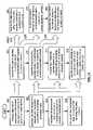
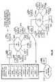
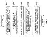
- FIG. 18illustrates a logic diagram of a method for providing broadband communication over power lines in accordance with the present invention
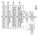
- FIG. 19illustrates a logic diagram of further processing of the data of Step 362 of FIG. 18 ;
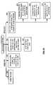
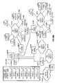
- FIG. 20illustrates a logic diagram of a method for providing broadband communication over power lines in accordance with the present invention
- FIG. 21Ais a block diagram illustrating various system configurations of the present invention in which one or more transformers reside within signal paths between power line nodes and power line gateways;
- FIG. 21Bis a block diagram illustrating another system configuration of the present invention in which one or more transformers reside within signal paths between power line nodes and power line gateways;
- FIG. 22is a system diagram illustrating at a high level a power line termination module and a plurality of power line local area networks serviced according to the present invention
- FIG. 23is a partial system diagram illustrating in more detail the system of FIG. 22 ;
- FIG. 24Ais a system diagram illustrating a first alternate embodiment of the last-leg utility grid high-speed data communication network previously illustrated in FIGS. 22 and 23 ;
- FIG. 24Bis a system diagram illustrating a second alternate embodiment of the last-leg utility grid high-speed data communication network previously illustrated in FIGS. 22 and 23 ;
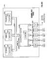
- FIG. 25Ais a block diagram illustrating a power line termination module constructed according to the present invention.
- FIG. 25Bis a partial system diagram illustrating the manner in which a power line gateway services a plurality of devices
- FIG. 25Cis a block diagram illustrating a power line node constructed according to the present invention.
- FIG. 25Dis a block diagram illustrating a power line gateway constructed according to the present invention.
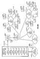
- FIG. 26is a logic diagram illustrating operation according to the present invention in enabling operation of a power line gateway
- FIG. 27is a logic diagram illustrating one manner for power line gateway authentication according to the present invention.
- FIG. 28is a logic diagram illustrating various operations of the power line termination module according to the present invention.
- FIG. 29is a logic diagram illustrating various operations of a power line gateway according to the present invention.
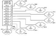
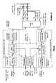
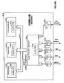
- FIG. 1illustrates a schematic block diagram of a power line based communication system 10 .
- the system 10includes a plurality of substation transformers 12 and 14 , a plurality of local transformers 30 , 32 , 18 , and 20 , a plurality of power line nodes 34 , 36 , 22 , and 24 , a plurality of local area networks 26 , 28 , 38 , and 40 , and a power line termination module 16 .
- more or less substation transformers, local transformers, power line nodes, power line termination modules, and local area networksmay be included in a communication system that provides similar communication services as that of the power line base communication system 10 . Accordingly, the elements illustrated, and the quantities thereof, are in no way to be construed as to limit the number of elements that may be included in the communication system 10 but are shown to illustrate the concepts of the present invention. The same applies to each figure of the present patent application.
- the substation transformers 12 and 14are coupled to high voltage power lines.
- the high voltage power linesprovide a 3-phase high voltage signal to each of the substation transformers.
- the voltage of the high voltage signalmay be 69 kilovolts AC (KVAC), 138 KVAC, 345 KVAC, etc.
- KVAC69 kilovolts AC
- the substation transformers 12 and 14convert the 3-phase high voltage signal into a lower voltage 3-phase signal.
- the output voltage of each substation transformer 12 and 14may be 12.5 KVAC, 13.8 KVAC, or 25 KVAC.
- Each of the local distribution transformers 18 , 20 , 30 and 32receives the 3 phase 12.5, 13.8 KVAC, or 25 KVAC signal from the respective substation transformer 12 or 14 and produces a single-phase 120 volt AC (VAC) or 240 VAC output. Accordingly, the single-phase 120 VAC or 240 VAC output is provided to a plurality of homes 60 - 62 , 68 - 70 , 76 - 78 , and 84 - 86 within each local area network 26 , 28 , 38 and 40 via power lines 46 , 48 , 42 , and 44 . Accordingly, each home within a local area network is coupled to each other home in the LAN via power lines of its local transformer. As such, the power lines 42 , 44 , 46 or 48 , carry the single phase 120 VAC or 240 VAC signal to each of the homes to supply the home with its requisite energy needs.
- Each local area network 26 , 28 , 38 and 40has a power line node 22 , 24 , 34 and 36 operably coupled to it. As shown, each power line node 22 , 24 , 34 and 36 is operably coupled to the local area network 26 , 28 , 38 and 40 via power lines 42 , 44 , 46 and 48 and also to a power line termination module 16 via a high-speed communication path 50 , 52 , 54 and 56 . As configured, the power line nodes 22 , 24 , 34 and 36 provide the last 100 feet, or so, of broadband coupling for the local area networks 26 , 28 , 38 and 40 . As is known, the last 100 feet, or so, of a communication path is one of the most financially significant portion of the communication network.
- the power line nodes 22 , 24 , 34 and 36 in combination with the power line gateways 64 , 66 , 72 , 74 , 80 , 82 , 88 and 90provide an economical and reliable communication network for the last 100 feet, or so, of a communication system.
- the power line nodes 22 , 24 , 34 and 36transceive data via the high-speed communication paths 50 , 52 , 54 and 56 with the power line termination module 16 for their respective local area networks.
- the power line termination module 16is operably coupled to a communication network 58 , which may be the Internet, public switched telephone network (PSTN), wireless network, Ethernet network, public wide area network, private wide area network, and/or any other network that routes data amongst a plurality of users as electrical signals and/or as light waves.
- PSTNpublic switched telephone network
- Ethernet networkpublic wide area network
- private wide area networkprivate wide area network
- any other networkthat routes data amongst a plurality of users as electrical signals and/or as light waves.
- the power line termination module 16acts as a local switch for the power line nodes 22 , 24 , 34 and 36 and their respective local area networks.
- Each of the power line nodes 22 , 24 , 34 and 36transceives data via the high-speed communication path 50 , 52 , 54 and 56 .
- the inbound data received by the power line node 22 , 24 , 34 or 36is destined for one or more of the users (i.e., homes, within the respective local area network).
- the inbound local area network datais processed then and modulated onto the power lines 42 , 44 , 46 or 48 .
- Each of the power line gateways 64 , 66 , 72 , 74 , 80 , 82 , 88 and 90include AC coupling to receive the modulated signal from the power lines.
- the power line gateways 64 , 66 , 72 , 74 , 80 , 82 , 88 and 90demodulate the data, process the data and retrieve the local area data for its respective home, (i.e., user).
- a usermay be a personal computer, printer, facsimile machine, audio equipment, video equipment, in-home network, and/or any device that can receive and/or transmit digital information.
- each of the power line gateways 64 , 66 , 72 , 74 , 80 , 82 , 88 and 90receives data from a user within the respective home, processes the data and modulates it onto the respective power lines.
- the respective power line nodereceives the modulated data, demodulates it, processes it, and places it on the high-speed communication path for transmission to the power line termination module 16 .
- the power line termination module 16then processes the data and routes it either to another user within one of the other local area networks or to the communication network 58 .
- FIG. 2illustrates a schematic block diagram of another power line base communication system 100 .
- the system 100includes four local area networks 26 , 28 , 38 and 40 , a pair of substation transformers 12 and 14 , a plurality of local distribution transformers 18 , 20 , 30 and 32 and a pair of power line nodes 24 and 36 .
- Each of the local area networks 26 , 28 , 38 and 40include a plurality of homes 76 - 78 , 84 - 86 , 60 - 62 , and 68 - 70 , respectively.
- Associated with each home in each local area networkis a power line gateway.
- power line gateway 64is associated with home 60 ;
- power line gateway 66is associated with home 62 , et cetera.
- Local distribution transformer 30is shown to include a high voltage capacitor 102 coupled in parallel with its primary and secondary windings.
- local distribution transformer 32also includes a high voltage capacitor 104 coupled in parallel with its primary and secondary windings.
- the high voltage capacitors 102 and 104provide a low impedance path for the modulated data produced by the power line gateways 64 , 66 , 72 and 74 to the power line node 36 .
- power line node 36may act as the conduit with the power line termination module 16 for both LAN 39 and LAN 40 .
- the high voltage capacitors 102 and 104may be a single high voltage capacitor having a capacitance of 100 pF to 10 ⁇ F and have a voltage rating in excess of 240 VAC.
- the high voltage capacitors 102 and 104may include multiple capacitors coupled in series and/or in parallel to achieve a desired capacitance and voltage rating.
- multiple capacitorsmay be used to coupled multiple taps, or nodes, of the primary winding to multiple taps, or nodes, of the secondary winding, and are coupled to the same phases of the primary and secondary winding for multiple phase transformers.
- Local distribution transformers 18 and 20have their secondary windings operably coupled together via high voltage capacitor 106 .
- the modulated data produced by the power line gateways within local area networks 26 and 28are readily coupled to the power line node 24 .
- power line node 24supports both local area networks 26 and 28 .
- power line node 24acts as the conduit to the power line termination module 16 , and hence the communication network, for all users within local area network 26 and 28 .
- the local transformers 32 and 30will have sufficiently low series impedance in a frequency of interest so that the modulated data will pass through the transformers 30 and 32 substantially or fully unattenuated. In this case, coupling capacitors 102 and 104 are not required.
- repeaters 75may be required to boost the signal strength of the modulated data. Whether repeaters 75 will be required, placement of the repeaters 75 , and the gain required for the repeaters 75 will typically be unique to each installation. A repeater 75 was shown in FIG. 1 and other repeaters 75 are shown in the subsequent Figures.
- the system 100 of FIG. 2provides the last 100 feet, or so, of a communication network (i.e., the individual coupling to each home within each LAN, or neighborhood) is provided via the power line nodes 24 and 36 , the power line gateways 64 , 66 , 72 , 74 , 80 , 82 , 88 and 90 and the existing power lines associated with the local distribution transformers.
- a communication networki.e., the individual coupling to each home within each LAN, or neighborhood
- the power line gateways 64 , 66 , 72 , 74 , 80 , 82 , 88 and 90and the existing power lines associated with the local distribution transformers.
- the power line nodes 22 , 24 , 34 and 36may be mounted near the local distribution transformers (i.e., on the same pole), incorporated into the local distribution transformer box, mounted at one of the homes within the local area network, or any convenient location between the transformer and the homes of the LAN.
- a local area networkmay generally be viewed as the homes within a neighborhood wherein each home within the neighborhood is powered by the same local distribution transformer.
- each LAN networkmay include 1-500 homes, small businesses, or other structures.
- each of the local distribution transformersmay include a modified fuse to have a desired frequency response.
- the modified fusemay have a predetermined inductance that provides high-frequency isolation to upstream data and filtering for down-stream data.
- the fusemay include a desired resistance and/or a desired capacitance to provide a more complex frequency response.
- FIG. 3illustrates a schematic block diagram of another power line base communication system 110 .
- the system 110includes a plurality of substation transformers (only one shown), a plurality of local distribution transformers 30 and 32 , and a plurality of local area networks 38 and 40 .
- power line nodes 112 and 114are associated with an individual home 62 and 68 , respectively, within the LAN they support.
- each of the power line nodes 112 and 114include a power line gateway 116 and 118 to facilitate transceiving data for the individual home 62 or 68 .
- Each of the power line nodes 112are operably coupled to the power line termination module 116 via a high-speed communication path 120 or 122 , which may be a fiber optic cable, wireless communication path, and/or any communication medium that allows 2 devices to transmit analog and/or digital information there between.
- a high-speed communication path 120 or 122which may be a fiber optic cable, wireless communication path, and/or any communication medium that allows 2 devices to transmit analog and/or digital information there between.
- the power line termination module 16includes a communication network interface 126 and a utility network interface 128 .
- the communication network interface 126allows the power line termination module 16 to be operably coupled to a communication network 58 .
- the communication network interface 126includes the multiplexing and de-multiplexing, switching, routing and/or other interconnections required to interface a plurality of local users with the communication network 58 .
- the utility network interface 128provides a similar function but with respect to a utility network 130 .
- Most power companieshave their own network to allow communication with substations, local distribution transformers, etc.
- the utility network 130may be utilized as at least a portion of the switching fabric to couple multiple local area networks associated with various substations together.
- the utility networkwill run on a given VLAN, which is totally separated with other users to ensure the security, privacy and QoS of the operation.
- the power line termination module 16also includes a user database 124 , which includes a listing of each user associated with each of the local area networks serviced by the power line termination module 16 . Such information includes, but is not limited to, user identification code, user access code, type of use, type of service, access information, access privileges, et cetera.
- the power line termination module 16provides the platform for system management and controls the high-speed data paths.
- the power line termination moduleincludes a fully redundant architecture that provides fault protection for the control of the system and for the connection to the communication network 58 .
- the power termination module 16provides platform interfaces for element management to support customers, or users on the network.
- the power line nodes of FIGS. 1 , 2 and 3generally provide the platform for a conversion of the high-speed electrical of light signals, which may be carried via wires, radio frequencies, and/or fiber optics, from the network into electrical signals that are transmitted over the power line infrastructure to the users of the LANs.
- the power line nodesmay physically reside at a location that provides the best intersection of the signal to the power network. Such possible locations include at the customer side of the substation transformer, at the customer side of the local distribution transformer, or at a home within the neighborhood serviced by the local distribution transformer.
- each of the power line nodesshould be weather proof such that no additional environment protection is needed.
- each of the substation transformersproduces a 3-phase high voltage signal.
- each phase produced by the substation transformermay carry separate modulated data for a local area network or a plurality of local area networks.
- a power line nodemay be located at the substation transformer on a one per phase basis (i.e., line to ground) to provide services such as meter reading, turn on-off electrical equipment within the home, burglar alarm activation/deactivation, et cetera.
- low speed signalingmay be used to test particular power networks to verify bandwidth capabilities.
- a power line nodewould typically serve in the range of 1-15 homes. In an area where more than 15 homes are supported by a local distribution transformer, a plurality of power line nodes may be utilized. To provide isolation on the power lines from power line node to power line node, and from local area network to local area network, different modulation frequencies may be utilized, the power lines may be frequency division multiplex, time division multiplex, and/or any other mechanism for isolating multiple signals on a single transmission path.
- the power line nodes and power line gatewaysmay include a battery backup, generator, and/or a fuel cell to power respective portions of the local area network as well as provide in home power when local services have been disrupted.
- a power line base communication systemmay be configured in accordance with FIGS. 1 , 2 and/or 3 .
- one local area networkmay include a power line node that is affiliated with a particular home
- one local area networkmay be supported by a power line node that is physically co-located with the local distribution transformer
- multiple local area networksmay be supported by a single power line node wherein AC coupling provides connectivity between local area networks.
- the substation transformermay include the power line node that provides communication to the entire network affiliated with that particular substation.
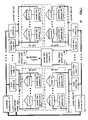
- FIG. 4illustrates a schematic block diagram of a representative local area network wherein the power line nodes 22 , 24 , 34 and 36 are shown in greater detail as well as the power line gateways 64 , 66 , 72 , 74 , 80 , 82 , 88 and 90 .
- the power line node, 22 , 24 , 34 or 36includes an AC coupling module 152 , a power amplifier 154 , a splitter 156 , a power line node inbound section 158 and a power line node outbound section 160 .
- the inbound and outbound sections 158 and 160are operably coupled to the high-speed communication path 50 through 56 .
- the power line node 22 , 24 , 34 or 36process inbound local area network data 140 and outbound local area network data 142 .
- inbound section 158 of the power line node 22 , 24 , 34 or 36processes the inbound local area network data 140 based on a desired communication convention. As such, the inbound local area network data 140 is received via the high-speed communication path 50 through 56 in accordance with a particular communication convention.
- the inbound section 158deciphers the local area network data 140 to identify the individual addressees, i.e., the individual users within the local area network it supports.
- the processed datais then modulated in accordance with a modulation protocol of the LAN and provided to splitter 156 .
- the power line gateways 64 , 66 , 72 , 74 , 80 , 82 , 88 and 90 , the power line nodes 22 , 24 , 34 , or 36 , and the power line termination module 16(as shown in FIGS. 1-3 ) each include one or more VLAN Switch modules.
- the VLAN operations of the present inventionwill be described further with reference to FIGS. 21-29 .
- Each of the power line gateways, 64 , 66 , 72 , 74 , 80 , 82 , 88 and 90are operably coupled to the power lines at the respective homes.
- Each of the power line gatewaysincludes an AC coupling module 162 , a power amplifier 164 , a splitter 166 , a power line gateway inbound section 168 and a power line gateway outbound section 170 .
- the modulated data that has been placed on the power lines by the AC coupling module 152 of the power line nodeis received via the AC coupling module 162 of the power line gateways.
- the received modulated signalsare provided to power amplifier 164 , which also may be of a conventional modem construct, amplifies the signals and provides the amplified signals to splitter 166 .
- the splitter 166which may be of conventional construct, separates the outbound signals, (i.e., the modulated signals received from the power line node) from the inbound signals (i.e., the received signals from the user that are to be modulated and provided to the power line node).
- the inbound datawill be modulated at a different frequency than the outbound data.
- the transmit pathi.e., from the power line node to the power line gateways
- receive pathi.e., from the power line gateways to the power line node
- the same frequencymay be used for transmit and receive paths.
- the communication pathwill be used for data transmission, i.e., from the power line node to the power line gateways, or data reception, i.e., from the power line gateways to the power line node.
- the power line gateway outbound section 170demodulates the data in accordance with the modulation/demodulation protocol of the LAN.
- the outbound section 170then processes the demodulated data in accordance with the LAN communication convention to produce retrieved data.
- the outbound section 170then provides the retrieved data to the home as user outbound data 146 .
- Each power line gatewaywill perform a similar function with respect to modulated inbound data on the power lines.
- the coupling of the power line gateway to the homemay be done through a modem, a direction connection, a connection into an in-home network, or any other means for provided data to a user.
- Each of the users within the homes 60 , 62 , 68 , 70 , 76 , 78 , 84 or 80also produce user inbound data 144 or 148 .
- the user inbound data 144 or 148is data generated by a user who desires to transmit it to the communication network to another user via the power line node. Note that if the user is communicating from home to home within the local area network, the power line node may facilitate the switching of the data such that the data is not provided on the high-speed communication path 50 or 56 . Similarly, if the initiating user and target user are supported by the same power line termination module, the power line termination module may provide the appropriate switching, and/or routing, to facilitate the communication.
- the power line gateway inbound section 168processes the data in accordance with the desired communication convention of the LAN and then modulates the process data in accordance with the modulation protocol of the LAN.
- the modulated datais provided to splitter 166 and then amplified by power amplifier 164 .
- the amplified signalis placed on the power lines via the AC coupling module 162 , which includes a pair of high voltage capacitors.
- the power line nodereceives the user inbound modulated user data via the power lines and the AC coupling module 152 , which provides the received signals to the power amplifier 154 .
- the power amplifier 154amplifies the received inbound modulated user data and provides the amplified data signals to the splitter 156 .
- the splitter 156separates the user inbound modulated data 144 or 148 from the inbound local area network data 140 .
- the power line node outbound section 160receives the modulated user data, demodulates it based on the modulation/demodulation protocol of the LAN to produce demodulated data.
- the outbound sectionthen processes the demodulated data from the plurality of power line gateways based on the communication convention of the high-speed communication path 50 - 56 .
- the outbound section 160places the data on the high-speed communication path 50 - 56 such that the power line termination module 16 subsequently receives it.
- the power line nodemay be coupled via the high-speed communication path to the communication network, such that the processed data is directly routed to the communication network.
- the communication convention used to transceive data via the high-speed communication path 50 - 56 between the power line nodes and the communication network and/or the power line termination module 16may be a different communication convention from the one used within each of the local area networks.
- the transmission of user inbound data 144may utilize a CSMA type process while the data on the high-speed communication path 50 - 56 may utilize a frame relay communication convention, ATM communication convention, other data packetized communication convention, or a frame based communication convention.
- each local area network with the power line based communication systemmay use a different communication convention, however, the communication convention between the power line nodes and the power line termination module will be the same.
- the modulation/demodulation protocolwhich may be amplitude modulation, frequency modulation, frequency shift keying, phase shift keying, quadrature amplitude modulation, discrete multi-tone, orthogonal frequency division multiplexing, and code division multiple access, used in each LAN may be the same or varying from LAN to LAN.
- FIG. 5illustrates a schematic block diagram of the local area network 38 or 40 of FIG. 3 .
- power line node 112includes a power line gateway 116 or 118 and is associated with home 62 or 68 .
- the power line node 112includes the AC coupling module 152 , the power amplifier 154 , the splitter 156 , a power line node inbound section 182 and a power line node outbound section 180 .
- the power line node inbound section 182is operably coupled to the high-speed communication path 50 - 56 to receive inbound local area network data 140 .
- the power line node inbound section 182interprets the inbound local area network data 140 to determine whether any of the data is destined for a user within home 62 or 68 . If so, the home's data is separated from the remainder of the LAN data and provided to the power line gateway 116 .
- the power line gateway outbound section 186processes the local area data for the user within home 60 or 62 and provides the user outbound data 146 to the home.
- the remainder of the inbound local area network data 140is processed by the power line node inbound section 182 in a similar fashion as the inbound local area network data was processed by power line node inbound section 158 of FIG. 4 .
- the user at home 62 or 68generates user inbound data 144 .
- the power line gateway inbound section 184 of power line gateway 116 or 118receives the user inbound data 144 , processes it in accordance with the communication convention and provides it to the power line node outbound section 180 .
- the power line gateway inbound section 184passes the user outbound data 146 directly to the power line node outbound section 180 .
- the power line node outbound section 180processes the received user outbound data 146 with the other data it receives via the power lines, the AC coupling module 152 , and the splitter 156 .
- the functionality of the power line node output section 180is similar to the functionality of the power line node output section 160 of FIG. 4 .
- the power line gateway 64 or 74 as shown in FIG. 5functions in a similar way as the power line gateways discussed with reference to FIG. 4 .
- the power line node 112 or 114is mounted to an individual home wherein the high-speed communication path 120 or 122 is provided directly to the home.
- power companiesmay provide a single fiber optic line, or other high-speed communication link, to one home within a neighborhood supporting a power line node as opposed to running such high-speed communication links to each home in the neighborhood.
- the one high-speed communication link, via the power line nodesupports the data needs of the entire neighborhood. By having one home directly coupled to a high-speed communication path as opposed to many, there is substantial installation cost savings.
- the cost savings in each neighborhoodis achieved by having the power line node 112 or 114 and a plurality of power line gateways providing the final 100 feet, or so, of a communication system.
- many homes that are physically inaccessible, or physically difficult to reach,can now receive broadband communication services.
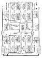
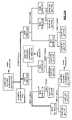
- FIG. 6illustrates a more detailed schematic block diagram of power line nodes 22 , 24 , 34 or 36 .
- the AC coupling module 152includes a pair of high voltage capacitors, which have a capacitance value depending on the frequency of the modulated data. For example, frequencies in the kilohertz range may require a relatively large capacitor, in the range of 10 to 100 ⁇ F (micro Farads), whereas modulated data in the megahertz range would require capacitors in the nF (nano Farad) range.
- Each of the capacitorsshould have a sufficient voltage rating to withstand a voltage differential supported by the power lines. For example, if the power lines are supporting 240 volts, the voltage rating of the capacitor should be in excess of 240 volts.
- the high voltage capacitors of the AC coupling module 152directly couple the power lines 42 , 44 , 46 , and 48 , to the differential output of a transmit power amplifier 154 T and to the inputs of a receiving power amplifier 154 R.
- the receiving power amplifier 154 Rprovides a differential output to the splitter 156 .
- the splitter 156also provides a differential input to the transmit power amplifier 154 T.
- the splitter 156outputs the received differential signal as the received output modulated data 208 to the power line node outbound section 160 .
- the power line node output section 160includes a demodulation module 202 , a data processing module 204 , and a transmitting module 206 .
- the demodulation module 202receives the outbound modulated data 208 , demodulates it to produce demodulated data 210 .
- the demodulation module 202uses a demodulation scheme that is dependent on the modulation scheme used to produce the modulated data 208 .
- the modulationand hence the corresponding demodulation scheme, may be amplitude modulation, frequency modulation, frequency shift keying, phase shift keying, quadrature amplitude modulation, discrete multi-tone encoding, orthogonal frequency division multiplexing, spread spectrum modulation, and/or any technique for transmitting and/or receiving data using a carrier frequency or plurality of carrier frequencies.
- the data processing module 204receives the demodulated data 210 and processes it in accordance with the desired communication convention to produce retrieved local area network data 212 .
- the communication conventionmay be time division multiplexing, frequency division multiplexing, CSMA, CSMA with collision avoidance, CSMA with collision detection, decryption, buffering, frame processing, data packetized information processing, and/or any other convention for conveying data through a switching fabric between users.
- the transmitting module 206receives the retrieved local area network data 212 and provides it as outbound local area network data 142 on the high-speed communication path.
- the transmit module 206may include an electrical interface such as a connector, may include an electrical to an optical interface, may include buffering, and/or any means for transmitting optical and/or electrical signals.
- the power line node inbound section 158includes a receiving module 190 , a data processing module 192 , and a modulation module 194 .
- the receiving module 190is operably coupled to receive inbound local area network data 140 via the high-speed communication path 50 - 56 .
- the receiving module 190may include an electrical interface, an optical to an electrical interface, buffering, and/or any means for receiving optical and/or electrical signals.
- the data processing module 192receives the inbound local area network data 196 and processes it in accordance with the communication convention to produce process data 198 .
- the communication conventionmay be in accordance with frame relay processing, time division multiplexing, ATM data packetizing data, other data packetizing conventions, label switched networks, multiple protocol label switching, CSMA, CSMA with collision avoidance, CSMA with collision detection, encryption, and/or buffering.
- the modulation module 194receives the processed data 198 and produces there from modulated data 200 .
- the modulation module 194modulates the processed data in accordance with the modulation protocol used within the LAN.
- a modulation protocolincludes amplitude modulation, frequency modulation, frequency shift keying, phase shift keying, quadrature amplitude modulation, discrete multi-tone modulation, orthogonal frequency division multiplexing, spread spectrum encoding, and/or any other modulation technique for placing a data signal onto a carrier frequency or a plurality of carrier frequencies.
- the splitter 156receives the modulated data 200 and provides it to the transmit power amplifier 154 T.
- the power amplifier 154 Tproduces a differential output that is provided to the AC coupling module 152 .
- the amplified modulated data 200is then placed on power lines 42 , 44 , 46 or 48 , which may be received by one or more of the power line gateways coupled to the respective power lines.
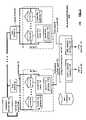
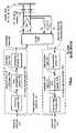
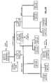
- FIG. 7illustrates a more detailed schematic block diagram of an embodiment of the power line node inbound section 158 and power line node outbound section 160 of FIG. 6 .
- the data processing module 192 of the inbound section 158includes a multiplexer 228 , a channel response determination module 226 and a mapping module 220 .
- the multiplexer 228is controlled by the channel response determination module 226 to output either received inbound local area network data 196 or test pattern data 230 . In normal operation, the multiplexer 228 will output the received inbound local area network data 196 .
- the channel response determination module 226produces test patterns 230 (i.e., known signals), which are outputted by multiplexer 228 .
- the test patternsare generated to enable the channel response determination module 226 to determine the frequency characteristics of the power lines within the local area network.
- the mapping module 220receives the inbound LAN data 196 or the test pattern 230 and maps the data into frequency bins based on the channel response 222 of the power lines.
- the mapped, or processed, data 198is then provided to the modulation module 194 .
- the functionality of the data processing module 192will be described in greater detail with reference to FIGS. 8 and 9 .
- the modulation module 194includes a modulator 232 , a digital to analog converter 234 , and a filter 236 .
- the modulator 232modulates the processed data 198 in accordance with the modulation protocol incorporated by the local area network.
- the modulated datais then converted to an analog signal via the digital to analog converter 234 .
- the analog signalis then filtered via filter 236 and provided as modulated data 200 .
- the output of modulator 232is also provided to an echo cancellation module 240 of the demodulation module 210 .
- the demodulation module 210includes a filter 238 , a summing module 242 , the echo cancellation module 240 , an equalizer 244 , a ranging module 246 , a multipath module 248 , an analog to digital converter 250 , and a demodulator 252 .
- the data processing module 204includes a demapping module 254 .
- the demodulation module 210may further include an error correction module that provides CRC verification, forward error correction, and/or any other type of conventional error correction to compensate for impulse noise, line variations, etc.
- the filter 238is operably coupled to filter the outbound modulated data 208 .
- the summing module 242subtracts the modulated data 200 via the echo cancellation module 240 from the filtered outbound modulated data 208 .
- the magnitude of the modulated data 200will in many cases be substantially greater than the magnitude of the outbound modulated data 208 .
- echo cancellationis required to accurately interpret the outbound modulated data 208 .
- the equalizer 244is operably coupled to receive the output of summing module 242 and is programmed by the channel response determination module 226 via a channel control signal 256 to equalize the magnitude of the signals in the frequency bins across the frequency of interest.
- carrier frequencies having lower frequenciestypically have a greater magnitude when transmitted over a distance than carrier frequencies having higher frequencies.
- environmental conditionscause variations in the performance of the power lines such that such frequency bins may have varying amplitudes.
- the equalizer 244is programmed based on the channel response determination module to equalize the energies within the frequency bins across the frequencies of interest.
- the channel response determination module 226determines the channel control signal 256 for the equalizer based on the processing of the test patterns 230 when received via the demodulation module 210 .
- the ranging module 246is programmed via the channel response determination module 226 via the channel control signal 256 to account for impedance variations of the loading on the power line.
- the multipath module 248is operably coupled to receive the output of the ranging module 246 to provide for compensation for multipath errors on the power lines.
- the level of error correctionis based on a channel control signal 256 as determined by the channel response determination module 226 .
- the demodulation module 210may include one or more of the equalizer, ranging module 246 and multipath module 248 . If the demodulation module 210 includes each of these elements, the control channel signal 256 will include separate signaling for each of these modules such that each module may be separately programmed.
- the correction for multipath error, ranging, and equalization of signalsis known, thus no further discussion will be presented except to facilitate the understanding of the present invention.
- the power linesmay be pre-tested (i.e., prior to the installation of the power line node and associated power line gateways), using a device that includes the channel response module 226 , the equalizer 244 , the ranging module 246 , and/or the multi-path module 248 .
- the elements of the power line node and power line gatewaysmay be tuned to provide more reliable initial operation.
- the analog to digital converter 250receives the output of the multipath module 248 and produces a digital representation thereof.
- the digital representationis provided to the channel response determination module 226 and to demodulator 252 .
- the demodulator 252demodulates the digital signal based on a demodulation protocol, which corresponds to the modulation protocol utilized to produce the modulated data 200 , to retrieve the data.
- the demodulated datais provided to the demapping module 254 , which, based on the channel response 222 , produces the retrieved local area network data 212 .
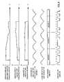
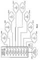
- FIGS. 8 and 9illustrate a graphical representation of the operation of the circuit of FIG. 7 .
- a test pattern 230is generated to include a series of bits, which may be representative of a pulse tone similar to the training sequences used in DSL modem-central office interaction.
- the mapping module 220based on the channel response 222 , produces processed data 198 .
- the mapping module 220maps the data of the test pattern 230 into test symbols identified by test symbol 1 , test symbol 2 , through test symbol n.
- the test symbolsmay be formatted in accordance with frame relay transmissions, data packetized transmissions, and/or label switching data packets.
- the processed data 198is modulated into an analog signal via the modulation module 194 .
- the modulated data 200is shown in the time domain for a single carrier frequency. If the modulation scheme utilizes a plurality of frequency bins, each frequency bin would have its own analog signal having a unique frequency. This is shown as the time domain representation of the modulated data 200 .
- the modulated data 200is also shown in the frequency domain.
- the 1 st representation of the frequency domainillustrates the modulated data 200 spanning a multitude of frequencies (e.g., 1 MHz to 10 MHz).
- the range of frequenciesincludes a plurality of frequency bins for transporting the processed data 198 once modulated.
- the frequency domain representation of the modulated data 200is shown in the right portion of the figure.
- the mapping moduleprocesses the received inbound local area network data 196
- the processed data 198will include symbols representing the inbound local area network data 196 as opposed to the test symbols representing the test pattern 230 .
- the representation of the modulated data in the time and frequency domainwill be similar.
- the plurality of power line gatewaysmay echo back the test patterns received from the power line node, or may generate their own test patterns to transmit to the power line node.
- the demodulation module 210receives the outbound modulated data 208 .
- the outbound modulated data 208is shown in both the time and frequency domains. As shown in the time domain, the triangular waveform of the modulated data 200 has been distorted into a triangle-like shape signal due to distortion caused by the characteristics of the power line.
- the frequency domain representation of the modulated data 208has the amplitude, or available bits per carrier frequency, vary with respect to the frequency. If the modulation, and corresponding demodulation technique utilizes a single carrier frequency, the frequency domain representation of the output modulated data 208 would appear on the right and have some corresponding phase shifting.
- the channel response determination module 226receives the outbound modulated data 208 via the analog to digital converter. Based on the difference between the modulated data 200 and the received outbound modulated data 208 during the test condition, the channel response determination module 206 generates the channel control signal 256 for the equalizer 244 , the ranging module 246 and/or the multipath module 248 . In addition, the channel response determination module 226 , based on the frequency domain of the output modulated data, generates the channel response information 222 that is used by the mapping module 220 . For instance, as shown in FIG. 8 with respect to the frequency domain representation of the outbound modulated data 208 , the amplitude of the signal drops dramatically as the frequency increases such that the bit capacity with bins in that frequency range may be unusable. As such, the channel response information provided to mapping module 220 would indicate that the bins in this frequency range would not carry data or would carry a minimal amount of data.
- FIG. 9illustrates a portion of the demodulation module 210 after the equalizer 244 , ranging module 246 , and multipath module 248 have been programmed via the channel response determination module 226 .
- the received outbound modulated data in the frequency domainis represented.
- the channel response determination module 226determines the response 260 of the equalizer 244 . This is shown in the frequency domain.
- the output 262 of equalizer 244is more linear. This is represented as the output 262 of equalizer 244 .
- the output 262 of equalizer 244is shown in the time domain.
- the output of equalizer 262is more representative of a triangular waveform, which corresponds to the modulated data 200 .
- the ranging module 246adjusts the reflected impedance of the demodulation module 210 based on the impedance of the power line.
- the multipath module 248corrects for multipath error, which distorts the signal. As such, the multipath modulator 248 corrects for phase shifting irregularities and distortion due to multipath error.
- the single carrier time domain representation of the output of multipath module 248is shown as output 264 .
- the analog signals, or signals of the modulated data 208after being processed by the equalizer 244 , the ranging module 246 and/or the multipath module 248 , are converted into a digital signal via the analog to digital converter 250 .
- the demodulator 252demodulates the digital signals to produce the demodulated data 210 .
- the demodulated datais represented by symbols 1 , 2 , 3 , et cetera.
- the demapping module 254receives the demodulated data 210 represented by symbols to produce the retrieved local area network data 212 .
- FIG. 10illustrates a graphical representation of the power line gateways 64 , 66 , 72 , 74 , 80 , 82 , 88 or 90 .
- the gatewayincludes a power line gateway inbound section 168 , a power line gateway outbound section 170 , a splitter 166 , Tx and Rx power amplifiers 164 T and 164 R, and an AC coupling module 162 .
- the power line gateway inbound section 168includes a receiving module 272 , a data processing module 274 , and a modulation module 276 .
- the receiving module 272which may be an electrical interface, an optical to electrical interface, and/or a buffer, receives the user inbound data 144 or 148 via a user communication path 270 .
- the user communication pathmay be an in-home system, phone lines, Ethernet connection, direct connect, wireless connection, and/or any mechanism within a home to couple data to a device outside of the home.
- the data processing module 274receives the inbound user data 278 and processes it in accordance with the desired communication convention to produce the processed data 280 .
- This moduleis a VLAN Switch, with a subset protocol defined in the IEEE 802.1Q and IEEE 802.1P.
- the modulation module 276receives the processed data 280 and produces there from modulated data 282 .
- the modulation module 276utilizes a modulation protocol to produce the modulation data.
- the modulation protocolis as previously discussed which may be, but is not limited to, amplitude modulation, frequency modulation, frequency shift keying, phase shift keying, quadrature amplitude modulation, discrete multi-tone modulation, orthogonal frequency division multiplexing, spread spectrum encoding, and/or any other technique for modulating data on a carrier frequency or a plurality of carrier frequencies.
- the splitter 166receives the modulated data 282 and provides it to the transmit power amplifying 164 T.
- the power amplifier 164 Tproduces a differential output that is provided to the AC coupling module 162 .
- the AC coupling module 162includes a pair of high voltage capacitors that provide AC coupling of the output of the power amplifier 164 T to power lines 42 , 44 , 46 or 48 .
- the AC coupling module 162provides AC coupling of modulated data on power lines 42 , 44 , 46 and 48 to the inputs of the receive power amplifier 164 R.
- the differential output of received power amplifier 164 Ris provided to splitter 166 .
- the splitter 166provides the received outbound modulated data 284 to the power line gateway outbound section 170 .
- the power line gateway outbound section 170includes a demodulation module 286 , a data processing module 290 , and a transmitting module 292 .
- the demodulation module 286receives the received outbound modulated data 284 and demodulates it based on the modulation/demodulation protocol.
- the data processing module 290receives the demodulated data 294 and processes it in accordance with the desired communication convention to produce retrieved user data 296 .
- the transmitting module 292provides the retrieved user data 296 as user outbound data 146 or 150 to the user via the user communication path 270 .
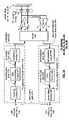
- FIG. 11illustrates a more detailed schematic block diagram of the power line gateway inbound section 168 and power line gateway outbound section 170 of FIG. 10 .
- the data processing module 274includes a multiplexer 301 and a formatting module 300 .
- the multiplexer 301is operably coupled to receive either received inbound user data 278 or test pattern data 279 . The selection is based on an input received via the channel response module 326 .
- the channel response module 326functions in a similar manner as the channel determination module 226 of FIG. 7 .
- the multiplexer 301outputs the received inbound user data 278 .
- test modei.e., in a mode to determine the characteristics of the power lines
- the multiplexer 301outputs the test patterns 279 .
- the formatting module 300is operably coupled to receive the output of multiplexer 301 and format the data to produce processed data 280 .
- the formatting of the datais in accordance with the communication convention used within the local area network.
- the formattingmay be data packetizing the data, placing the data in a corresponding time frame, and/or any other communication convention for relaying data via a switching fabric.
- the modulation module 276includes a modulator 302 , a digital to analog converter 304 and a filter 306 .
- the modulator 302is operably coupled to receive the processed data 280 and produce there from modulated data.
- the digital to analog converter 304converts the modulated data into an analog signal that is filtered and outputted as the modulated data 282 .
- the demodulation module 286includes a filter 308 , an echo cancellation module 310 , a summing module 312 , an equalizer 314 , a ranging module 316 , a multipath module 318 , an analog to digital converter 320 , and a demodulator 322 .
- the functionality of these elements, as well as the functionality of the channel response module 326is similar to the functionality of corresponding elements of the demodulation module 210 as shown in FIG. 7 . While the functionalities are similar, each power line gateway will determine its own channel response characteristics to provide the necessary equalization for equalizer 314 as well as separate multipath error correction and ranging functions.
- the data processing module 290includes a deformatting module 324 that deformats the data to produce the retrieved user data 296 .
- the deformatting used by deformatting module 324is the inverse of the protocol used by formatting module 300 .
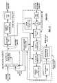
- FIG. 12illustrates a schematic block diagram of the power line node 112 of FIG. 5 .
- the power line node 112includes a power line node inbound section 158 , a power line gateway 116 , a power line node outbound section 160 , splitter 156 , transmit and receive power amplifiers 154 T and 154 R, and an AC coupling module 152 .
- splitter 156 , power amplifiers 154 and AC coupling module 152are as previously described.
- the power line node inbound section 158includes a receiving module 190 , data processing module 330 , and modulation module 194 .
- the receiving module 190 and the modulation module 194functions in a similar manner as the same reference numbered modules of FIG. 6 .
- the data processing module 330is included within the power line node inbound section 158 as well as within the power line gateway 116 . In operation, the data processing module 330 will identify the user inbound data 144 contained within the inbound local area network data 140 . When the data processing module 330 recognizes the user inbound data 144 , it provides the data to the transmitting module 292 . As such, the user inbound data 144 is not modulated nor is it propagated onto the power lines.
- the remainder of the inbound local area network data 140is processed to produce the processed data 198 and propagated via the modulation module 194 , splitter 156 , power amplifier 154 T and AC coupling module 152 onto the power lines.
- the power line node outbound section 160includes a demodulation module 202 , a data processing module 332 , and a transmitting module 206 .
- the transmitting module 206 and demodulation moduleperform in a similar fashion as like referenced elements of FIG. 6 .
- the data processing module 332is operably coupled to receive demodulated data 210 via the demodulation module 202 and user outbound data 146 via the receiving module 272 .
- the data processing module 332processes the user outbound data 146 and the demodulated data 210 to produce retrieved local area network data 212 .
- the retrieved local area network data 212is outputted via transmitting module 206 as output local area network data 142 .
- the transmitting module 292 and receiving module 272communicate via the user communication path 270 with the affiliated user of the power line node 112 .
- the power line node 112may be mounted at the home of a user.
- fiber, or other high-speed communication pathis routed to one individual home within a local area network, or neighborhood, where the power line node 112 provides the conduit for high-speed communications for other homes within the neighborhood via the power lines without the need for installation of high-speed communication paths to each of the homes in the local area network. Since a substantial portion of the cost of installing a communication system is the equipment of the last 100 feet, the power line node and power line gateways of the present invention substantially reduce the cost of bringing broadband communications to users that already have electricity.
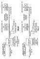
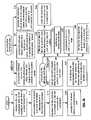
- FIG. 13illustrates a schematic block diagram of a distributed power line base communication system.
- the power line base communication systemincludes a communication network 340 , a utility network 342 , a central office 352 , a plurality of power line termination modules 16 and 354 , a plurality of power line nodes 34 , 22 , 24 and 36 , a plurality of local distribution transformers 18 , 20 , 30 and 32 , and a plurality of power line gateways 64 , 66 , 72 , 74 , 80 , 82 , 88 and 90 .
- the power line nodes 22 , 24 , 36 , 34 and 36are coupled via a high-speed communication path to the communication network 340 and/or the utility network 342 .
- the communication network 340may be the Internet, wide area network, wireless communication system, public switch telephone network, Ethernet network, and/or any other type of networking system.
- the utility network 342is a communication network private to a utility company or power company used to communicate with substations, local distribution transformers, and other nodes within a power system throughout a geographic region.
- the central office 352coordinates the communication throughout the communication system of FIG. 13 .
- Each of the power line termination modules 16 and 354supports a portion of the system of FIG. 13 .
- Each of the power line nodesincludes a processing module 344 and memory 346 .
- the processing module 344may be a single processing device or a plurality of processing devices. Such a processing device may be a microprocessor, micro controller, digital signal processor, state machine, logic circuitry, programmable gate array, analog circuitry, and/or any device that manipulates signals (analog or digital) based on operational instructions.
- the memory 346may be a single memory device or a plurality of memory devices. Such a memory device may be a read only memory, random access memory, re-programmable memory, system memory, magnetic tape memory, and/or any device that stores digital information.
- processing moduleimplements one or more of its functions via a state machine, logic circuitry, and/or analog circuitry
- the memory storing the corresponding instructionsis embedded within the circuitry comprising the state machine, logic circuitry, and/or analog circuitry.
- the operational instructions stored in memory 346 and performed by processing module 344are discussed in greater detail with reference to FIGS. 18 through 20 .
- Each of the power line gatewaysincludes a processing module 348 and memory 350 .
- the processing module 348may be a single processing device or a plurality of processing devices. Such a processing device may be a microprocessor, micro controller, digital signal processor, state machine, logic circuitry, programmable gate array, analog circuitry, and/or any device that manipulates signals (analog or digital) based on operational instructions.
- the memory 350may be a single memory device or a plurality of memory devices. Such a memory device may be a read only memory, random access memory, re-programmable memory, system memory, magnetic tape memory, and/or any device that stores digital information.
- processing moduleimplements one or more of its functions via a state machine, logic circuitry, and/or analog circuitry
- the memory storing the corresponding instructionsis embedded within the circuitry comprising the state machine, logic circuitry, and/or analog circuitry.
- the operational instructions stored in memory 350 and performed by processing module 348are discussed in greater detail with reference to FIGS. 18 through 20 .
- a power line nodemay have a high-speed communication path to the communication network 340 and/or to the utility network 342 .
- the power line termination module 16 and/or 354coordinates the communication via local area networks utilizing networks 340 and/or 342 .
- FIG. 14illustrates a graphical representation of processing of inbound local area network data 140 when the data is formatted in accordance with IEEE 802.1Q VLAN.
- the inbound local area network data 140includes frame sync information and data within a frame.
- the power line node 34receives the inbound local area network data 140 via the high-speed communication path 50 .
- the power line node 34identifies the users, and/or addressees, within the frame of information based on time slot allocations within the frame. Having identified each user and its corresponding data, the power line node 34 uniquely encodes the data based on the users individual encoding and/or encryption mechanism.
- the datais then time and/or frequency division multiplexed and transmitted as modulated data 200 via the power lines 46 to the power line gateways 66 and 64 .
- the modulated datawill have a varying bit per carrier ratio over the frequency range of interest. This is illustrated as the modulated data 200 .
- Each of the gateways 64 and 66will demodulate the modulated data 200 and identify its corresponding timeslot for its respective user. Having done this, the data is decoded and/or decrypted based on the individual encoding and/or encryption of the individual user to retrieve the data contained within the user's timeslot or slots. Such data is then presented as user outbound data 146 or 150 to the respective user.
- FIG. 15illustrates a graphical representation of processing outbound local area network data 142 by power line node 34 .
- the outbound local area network data 142is organized as frames of data. Each frame is separated by frame syncing information such that the alignment of frames can be readily obtained to ensure proper transmission of data.
- the outbound local area network data 142is transmitted via the high-speed communication path 50 .
- each of the power line gateway 64 and 66receive user inbound data 144 or 148 .
- the user inbound datais encoded utilizing a unique encoding and/or encryption scheme for the individual users.
- the encrypted datais then placed in a corresponding timeslot or slots for the individual user and the data is modulated to produce the modulated data 200 .
- each power line gateway 66may have a corresponding frequency bin or plurality of frequency bins to provide its modulated data to the power line node 34 .
- each of the power line gateways 64will transmit its data in a particular time increment utilizing the entire frequency spectrum allocated for demodulated data 200 .
- the power line node 34identifies the users by the carrier frequencies, and/or the time of the data being received.
- the datais then decoded utilizing the unique decoding scheme and/or decryption scheme for the individual users.
- the user datais then placed into frames according to timeslot allocations and provided as the output local area network data 142 .
- FIG. 16illustrates a graphical representation of the power line node 34 processing inbound local area network data 140 when the data 140 is data packetized data.
- the power line node 34receives the data packets of data via the high-speed communication path 50 using orthogonal frequency division multiplexing (OFDM).
- OFDMorthogonal frequency division multiplexing
- the power line node 34separates the data packets to identify the individual addressees of the data. Utilizing a unique encoding and/or encryption scheme for each user, the separated data is encoded.
- the encoded data packet for each useris then tagged and modulated.
- the modulated data 200is provided on power lines 46 to power line gateways 64 and 66 .
- Each of the power line gateways 64 and 66demodulates the received modulated data 200 to retrieve the data packets of data.
- the data packets of dataare then identified to determine whether they are addressed for the individual user associated with the power line gateway. If so, the corresponding data packets are decoded and/or decrypted to retrieve the user outbound data 146 or 150 .
- FIG. 17illustrates a graphical representation of producing outbound local area network data 142 in a data packetized format.
- each of the power line gateways 64 and 66receive user inbound data 144 or 148 via its corresponding user.
- Each power line gateway 64encodes the corresponding data, packetizes it and then modulates it onto power lines 46 .
- the transmission of the modulated data onto the power lines 46may be done in a CSMA manner, and/or time allocated manner.
- the power line node 34receives the outbound modulated data 208 and identifies the particular users. Having identified the particular users, the data is decoded and/or decrypted based on the individual encoding and/or encryption scheme for the corresponding user. The data for the local area network is then data packetized and placed on the high-speed communication path 50 as the outbound local area network data 142 .
- FIG. 18illustrates a logic diagram of a method for providing broadband communication over power lines.
- the processbegins at Step 360 where data that is associated with at least one user of a plurality of users in an area network (e.g., wide area network or local area network) is received.
- the datamay be received in a variety of manners, which will be subsequently described.
- the processthen proceeds to Step 362 where the data is processed based on a desired communication convention to produce process data.
- the desired communication conventionis IEEE 802.1Q VLAN. A more detailed discussion of the processing of the data in accordance with the desired communication convention will be subsequently described.
- Step 364the processed data is modulated based on a modulation protocol.
- the modulation protocolmay be amplitude modulation, frequency modulation, frequency shift keying, phase shift keying, quadrature amplitude modulation, discrete multi-tone modulation, orthogonal frequency division multiplexing, and/or spread spectrum modulation.
- the processthen proceeds to Step 366 where the modulated data is AC coupled to the power lines servicing the area network. This was graphically illustrated with reference to FIGS. 1 through 7 .
- the receiving of datamay be done in a variety of ways.
- the datamay be received in data packets via a high-speed communication path that is coupled to a communication network.
- the processing of the datacorresponds to Steps 372 through Step 376 .
- the datais logically separated based on addresses of the plurality of users to produce separated data packets of data.
- the processthen proceeds to Step 374 where the separate data packets of data are encoded based on a corresponding encoding process of the user. Note that each user of the local area network has an individual encoding scheme and/or encryption scheme.
- Step 376the encoded data packets are tagged in accordance with CSMA, CSMA with collision avoidance, and/or CSMA with collision detection.
- the datamay be received as shown at Step 368 where it is received via a utility network.
- the utility networkcouples a plurality of substations to a control center.
- the datais relatively low speed to provide the control central office with remote metering, enabling/disabling of electronic devices within a home, and/or other functions to control the transient use of power within a given area supported by a local distribution transformer and/or substation.
- the datamay be received as shown at Step 378 where it is received in frames via a high-speed communication path coupled to a communication network. If the data is received in this manner, the processing is done as shown in Step 380 .
- the datais multiplexed within the frames based on division multiplexing (e.g., time division multiplexing and/or frequency division multiplexing) of the frames among the plurality of users. This was graphically illustrated in FIGS. 14 and 15 .
- FIG. 19illustrates a logic diagram of further processing options of the data of Step 362 of FIG. 18 .
- Each of these pathsprovides alternate and/or cumulative processing of the data.
- the datamay be buffered.
- the datamay be encrypted based on an encryption protocol that is unique to each user within the system.
- local datamay be identified wherein the local data addresses a user affiliated with the power line node. The process then proceeds to Step 396 where the local data is routed to the local user without further processing.
- the processingmay include determining the channel response of the power lines over a frequency range of interest. For example, if the data is being transmitted via a plurality of carrier frequencies in the range of 100 kilohertz to 5 megahertz, the channel response in this frequency range is of interest.
- the processthen proceeds to one or more of Steps 400 through 404 .
- the datais mapped into frequency bins based on the channel response of the power lines.
- variations in the line impedance of the power linesare compensated for based on the response of the power lines.
- multipath errorsare compensated for of the power line in response to determining the power line frequency performance response.
- FIG. 20illustrates a logic diagram of a method for providing broadband communications over power lines.
- the processbegins at Step 410 where outbound modulated data is received via AC coupling to power lines of a local transformer.
- the processthen proceeds to Step 412 where the received outbound modulated data is demodulated based on a demodulation protocol.
- the particular demodulation protocolwill be the inverse of the modulation protocol used to modulate the data.
- the processthen proceeds to Step 414 where the demodulated data is processed based on the desired communication convention.
- the processing of the datawill be further discussed with reference to Steps 424 through 436 .
- the processthen proceeds to Step 416 where the retrieved data is provided to a communication path.
- the providing of the retrieved datawill be further discussed with reference to Steps 418 through 422 .
- the providing of the retrieved datamay include one or more of the processing steps shown in Steps 418 through 422 .
- the retrieved datais provided in frames via a high-speed communication path to a communication network.
- the retrieved datais provided in data packets via a high-speed communication path to a communication network.
- the retrieved datais provided via a communication path to a utility network that couples a plurality of substations to a control center.
- the retrieved datamay be user data and is provided to a user via a user communication path.
- the processing of the demodulated datamay be done utilizing one or more of the steps represented by Steps 424 through 436 .
- Step 424local data of the demodulated data is identified based on the address of a local user of the plurality of users. Once the local data is identified, the process proceeds to Step 426 where the local data is routed to the local user via a local communication path.
- the demodulated datamay be decrypted based on a decryption protocol of the at least one user wherein the decryption protocol corresponds to the modulation protocol.
- the demodulated datamay be buffered for controlling the timing of processing the data.
- the demodulated datamay be processed to compensate for multipath errors of the power lines.
- the demodulated datamay be demultiplexed within the frames based on division demultiplexing (time and/or frequency) of the frames amongst the plurality of users.
- the demodulated datamay be demapped from the frequency bins based on a channel response of the power lines.
- FIG. 21Ais a block diagram illustrating various system configurations of the present invention in which one or more transformers reside within signal paths between power line nodes and power line gateways.
- Three separate power line termination modules/power line nodes 2102 , 2152 , and 2154are shown in FIG. 21A , any of which could service the high-speed communication requirements of each of the power line gateways 2122 , 2124 , 2126 , 2128 , 2130 , 2132 , 2134 , 2136 , and 2138 .
- each of the power line termination modules/power line nodes 2102 , 2152 , and 2154couple to the utility grid at different locations.
- each of the power line termination modules/power line nodes 2102 , 2152 , and 2154will use different signal paths through the utility grid.
- the utility grid of FIG. 21 Aincludes a substation transformer 2100 that couples on its high side to a high voltage 3 phase power line, e.g., 138 KV, and services a 12.5 KV/3 phase distribution line on its low side.
- Distribution transformers 2104 and 2106couple to the 12.5KV/3 phase distribution line on their high side and service 480V/3 phase lines on their low sides.
- a plurality of business transformers 2110 , 2112 , 2114 , 2116 , 2118 , and 2120couple on their high sides to the 480V/3 phase lines and provide service to businesses at 240V/1 phase voltage levels.
- Each of the business transformers 2110 - 2120services at least one, and at most a few, businesses.
- Each of the power line gateways 2122 - 2138is shown as coupling to the 240V/1 phase portion of the utility grid. However, in other embodiments, some or all of the power line gateways 2122 - 2138 could couple to other portions of the utility grid.
- the transformers and conductors of the utility gridare designed to service the low frequency, e.g., 50 Hz, 60 Hz, power signal that is employed to provide electrical utility service to the business customers of the utility grid.
- the operating characteristics of the substation transformer 2100 , distribution transformers 2104 and 2106 , business transformers 2110 - 2120 , and power lines of the utility gridare well understood within this frequency band.
- the high-speed communication system of the present inventionoperates in a much higher frequency band, e.g., 3-30 MHz.
- the operational characteristics of the utility grid components within this frequency bandare not well understood.
- each of the transformersintroduces signal attenuation for data communication signals passing through the transformers, e.g., 20-30 dB.
- the utility gridincludes a plurality of conductive paths required to service the electrical utility needs of the customer. However, these conductive paths produce significant reflections when the utility grid is used to service high-speed data communications. Further, the various utility grid components that provide benefit for power factor correction, e.g., capacitor banks, may significantly affect the ability to use the utility grid to service high-speed data communications.
- the input impedance seen by the power line nodes and the power line gatewaysmay be such as to limit the ability of the devices to transmit signals within the utility grid. Further, the utility grid itself may offer varying impedance to the devices and cause frequency selective amplitude and phase distortion.
- FIG. 21Bis a block diagram illustrating another system configuration of the present invention in which one or more transformers reside within signal paths between power line nodes and power line gateways.
- the structure of FIG. 21Bincludes only the 12.5KV/3 phase and 240V/1 phase lines of the utility grid.
- distribution transformers 2156 and 2158couple on their high sides to the 12.5KV/3 phase voltage and couple on their low sides to the 240V/1 phase lines.
- Each of the power line gateways 2122 - 2138couple to the 240V/1 phase lines and corresponding homes are serviced at this same voltage.
- power line node 2102couples to the 12.5KV/3 phase line while power line nodes 2152 and 2154 couple to the 240V/1 phase lines.
- FIG. 21BThe structure of FIG. 21B is typically more common in a residential area while the structure of FIG. 21B is more typical in a commercial/industrial area.
- teachings of the present inventionapply equally as well to commercial/industrial areas as well as to strictly residential area.
- the system of the present inventionmay be employed to service a mixed commercial/industrial and residential neighborhood.
- FIG. 22is a system diagram that illustrates at a high level a power line termination module and a plurality of power line local area networks (LANs) serviced according to the present invention.
- Power line termination module 2202includes a plurality of ports, port 0 through port 7 . Each of this plurality of ports services a respective power line LAN.
- port 0services power line LAN 2206
- port 1services power line LAN 2208
- port 2services power line LAN 2210
- port 3services power line LAN 2212
- port 4services power line LAN 2214
- port 5services power line LAN 2216
- port 6services power line LAN 2218
- port 7services power line LAN 2220 .
- the power line termination module 2202also couples to data network 2204 , e.g., high-speed data networks such as the Internet.
- the power line termination module 2202serves as a Layer 3 edge router that connects the power line LANs to the data packet data network 2104 , e.g., IP network and provides Wide Area Network (WAN) access for a plurality of serviced power line gateways.
- the power line termination module 2202supports network security operations, Quality of Service (QoS) operations, and Privacy operations, among other operations.
- QoSQuality of Service
- Privacy operationsamong other operations.
- Each port of the power line termination module 2202supports a VLAN domain and has assigned thereto a VLAN group ID. Such VLAN domains may operate consistently with IEEE 802.1Q. In IEEE 802.1Q, a VLAN domain allows the addressing of 4,096 particular VLAN IDs. Thus, each port may service 4,096 individual VLANs according to the present invention.
- the power line termination module 2202performs VLAN-based traffic control, data packet data translations, and additional functions in servicing a plurality of respective power line gateways. In other embodiments, each port of the power line termination module 2202 may address a differing number of VLAN IDs. In any case, VLAN IDs may be reused at each port of the power line termination module 2202 because the ports of the power line termination module 2202 are physically isolated from one another and service differing power line LANs that are communicatively isolated from one another.
- each VLAN domainis on a subnet since the power line termination module 2202 is also an Edge Router that links the VLANs and data network 2204 in providing QoS WAN services.
- a Configuration Management Server (CMS) 2390couples to the power line termination module 2202 via the data network 2204 .
- the CMS 2390couples directly to the power line termination module.
- the CMS 2390is more readily able to service a plurality of power line termination modules.
- the CMS 2390services service provisioning operations, service updating operations, and other administrative functions required to service the system. These operations will be described further with reference to FIGS. 26-29 .
- FIG. 23is a partial system diagram illustrating in more detail the system of FIG. 22 .
- power line termination module 2202includes eight ports, port 0 through port 7 , each of which is capable of servicing a respective group of power line gateways coupled to the power line termination module 2202 via a power line LAN.
- power line nodes 2302 and 2304couple between the ports of the power line termination module 2202 and the respective serviced power line LANs.
- port 0 of power line termination module 2202couples to power line node 2302 , which services power line LAN 2206 .
- the structure of the power line nodeshas been previously described herein in detail and will be further described with reference to FIG. 25C .
- Power line LAN 2206services a plurality of power line gateways that are coupled to a respective utility grid segment. These power line gateways include power line gateways 2306 , 2308 , 2310 , 2312 , 2314 , 2316 , 2318 , and 2320 .
- each of these power line gateways 2306 - 2320has at least one VLAN ID therewith associated.
- Power line gatewaysare also referred to herein and otherwise as customer premises equipment (CPE).
- CPEcustomer premises equipment
- the power line gatewaysare referred to as CPEs because the power line gateways will be resident at the customer premises and will typically serve at least one device.
- Port 7 of the power line termination module 2202couples to power line node 2304 and services power line LAN 2220 .
- Power line LAN 2220corresponds to a respective utility grid segment.
- Serviced by power line LAN 2220are power line gateways 2322 - 2336 .
- each power line gateway 2322 - 2336includes a unique VLAN ID.
- each power line gatewaymay be assigned multiple VLAN IDs, each of which corresponds to a device serviced by the power line gateway.
- VLAN IDsmay be reused for each port such that power line gateways serviced by differing ports may have the same VLAN ID.
- This operationis possible because the power line termination module 2202 performs translation operations between VLAN IDs and data packet addresses, e.g., MAC address, IP address, etc.
- VLAN ID and data packet address translationis based upon the identity of devices coupled to serviced ports of the power line gateways. Because the VLAN domains serviced by the ports of the powerline terminal module 2202 are physically isolated, the use of the same VLAN IDs on differing ports does not cause address conflicts within the power line termination module 2202 .
- each power line LANaccesses the power line termination module 2202 via a unique servicing port.
- each power line gateway serviced by the power line LANoperates in a multiple access arrangement with each other power line gateway serviced by the power line LAN.
- the power line gateways 2322 - 2336 of power line LAN 2220operate in a multiple access arrangement with collision avoidance mechanisms in place.
- each power line gatewaymay receive transmissions from each other of the power line gateways.
- the VLAN operations of the present inventionserve to privatize communications on the power line LAN 2220 thus precluding power line gateways that share the power line LAN 2220 from receiving each other's communications.
- the VLAN operations of the present inventionalso support QoS operations on the power line LAN 2220 and support a number of other operations that provide significant benefits in the operation of the power line LAN 2220 and other power line LANs.
- FIG. 24Ais a system diagram illustrating a first alternate embodiment of the last-leg utility grid high-speed data communication network previously illustrated in FIGS. 22 and 23 .
- the power line termination module 2202couples to data network 2104 and includes a plurality of ports, i.e., port 0 through port 7 .
- the power line LAN 0has a plurality of unique segments, segments 1 - 4 .
- a power line termination module accumulator 2402couples to port 0 of power line termination module 2202 via a 1 GB optical link.
- the power line termination module accumulator 2402couples to power line nodes 2404 , 2406 , 2408 , and 2410 that service power line power line LAN 0 segments 2412 , 2414 , 2416 , and 2418 , respectively.
- the coupling between power line termination module accumulator 2402 and power line nodes 2404 - 2410is serviced via respective 100 MB optical links. Coupling at the lower capacity 100 MB links allows less expensive optical ports to be employed to service the same subscriber base. Such is the case because the higher rate 1 GB link is significantly more expensive than are 100 MB optical links.
- the 1 GB linkis serviced according to the 1 Gig-E optical standard, while the 100 MB links are serviced according to the 100 FX optical standard.
- the power line termination module accumulator 2402operates as an ISO Layer 2 aggregation switch.
- An advantage of the structure of FIG. 24Ais that a single power line termination module 2202 may service in excess of 25,000 power line gateways. These power line gateways may be disbursed over a relatively large geographic area.
- the power line termination module accumulator 2402may be located geographically closer to serviced power line gateways than is the power line termination module 2202 .
- each power line node 2404 - 2410may be located geographically close to its serviced power line LAN 0 segment 2412 - 2418 , respectively. In such case, significant advantages are obtained not only in bandwidth throughput and reduced device costs, but reduced deployment costs as well.
- the power line termination module 2202Because footprint requirements for the power line termination module 2202 can be great, it is advantageous to locate the power line termination module 2202 at a geographic location having minimal cost. In such case, the 1 GB link and 100 MB links, or such other links as appropriate, may be run between the power line termination module 2202 , power line termination module accumulator 2402 , and the power line nodes 2404 - 2410 . Not only can the power line termination module, power line termination module accumulator 2402 and power line nodes 2404 - 2410 be economically placed, but they can be placed such that they are optimally located with respect to their serviced power line gateways.
- each power line node 2404 , 2406 , 2408 , and 2410services a respective set of power line gateways coupled to corresponding LAN 0 segment 2412 , 2414 , 2416 , and 2418 , respectively.
- power line node 2404services power line gateways 2420 - 2434 .
- Each of these power line gateways 2420 - 2434has at least one unique VLAN ID associated therewith.
- power line node 2406services power line gateways 2436 - 2450 .
- each of the power line gateways 2436 - 2450has associated therewith at least one unique VLAN ID.
- power line node 2408servicing power line LAN segment 2416 and power line node 2410 servicing power line LAN segment 2418 .
- power line gatewaysserviced by each of these power line LAN segments 2416 and 2418 .
- each port of the power line termination module 2202services its own VLAN domain. Because only a single VLAN domain is serviced by port 0 , each VLAN ID may be used only a single time within the combined segments of power line LAN 0 (including LAN 0 segments 2412 , 2414 , 2416 , and 2418 ).
- the power line termination module accumulator 2402may simply be a data packet switch, which performs no operations relevant to the VLAN system of the present invention. However, in another embodiment, the power line termination module accumulator 2402 may perform some of the VLAN operations of the present invention.
- FIG. 24Bis a system diagram illustrating a second alternate embodiment of the last-leg utility grid high-speed data communication network previously illustrated in FIGS. 22 and 23 .
- a single power line node 2450includes a plurality of ports, each of which services a particular power line LAN, 241 , 2414 , 2416 , and 2418 .
- a structure of the power line node 2450 that supports this architectureis described in detail with reference to FIG. 25C .
- FIG. 25Ais a block diagram illustrating a power line termination module 2202 constructed according to the present invention.
- the structure illustrated in FIG. 25Ais a diagrammatic representation of the structure of the power line termination module 2202 with minimal detail. As the reader will appreciate, many various other structures may perform operations according to the present invention in servicing a last-leg utility grid high-speed data communication network.
- the power line termination module 2202includes a processor 2502 , memory 2504 , storage 2506 , a high speed interface 2508 , and a port interface 2512 , all of which couple via a system bus 2514 .
- Also contained within the power line termination module 2202is a data packet switch 2510 that couples to high-speed interface 2508 , a port interface 2512 , and the system bus 2514 .
- the high-speed interface 2508couples to either a plurality of data networks or couples redundantly to a single data network.
- Such data networkis referred to as “2204” in FIGS. 22 , 23 , 24 A, and 24 B.
- This data networkmay be an Internet, an Intranet, or another high-speed data packetized data network.
- the port interface 2512supports the eight ports of the power line termination module 2202 and couples to a respective power line node or power line termination module accumulator via an interface, e.g., FX fiber interface. Other embodiments of the power line termination module may include a greater number, or a lesser number of ports. Each port of the port interface 2512 implements a particular VLAN domain. VLAN operations and administrative operations are enabled by a plurality of software instructions that are executed by the power line termination module 2202 . Further, various other modifications of the power line termination module 2202 may be required to implement VLAN operations of the present invention. Software instructions that cause the VLAN operations upon execution, referred to as VLAN operations, are initially stored as VLAN operations 2516 in storage 2506 .
- the storage 2506may be an optical media, a hard drive, or other substantially static storage device.
- Memory 2504may include dynamic random access memory, read-only memory, or another type of memory that is known in the arts to facilitate the storage of instructions and data and that may be accessed by processor 2502 .
- Processor 2502may be a single microprocessor, multiple microprocessors, a processing module, or another processing device that is capable of executing software instructions and controlling the operation of other components coupled via system bus 2514 .
- the VLAN operations 2516are copied from storage 2506 to memory 2504 as VLAN operations 2518 and then read by the processor 2502 from memory 2504 as VLAN operations 2520 .
- the execution of these software instructions by the processor 2502causes the processor to program/control the operation of the port interface 2512 to perform VLAN operations 2522 according to the present invention.
- the VLAN operations 2520 performed by the processor and the VLAN operations 2522 performed by the port interface 2512enable the power line termination module 2202 to execute the VLAN operations of the present invention.
- the data packet switch 2510is generally known in the art to switch data packet data between coupled devices, e.g., between the high-speed interface 2508 and the port interface 2512 .
- the processor 2502controls the operation of the data packet switch 2510 to operate upon data packet data according to the present invention.
- the processor 2502programs the data packet switch 2510 to operate according to the present invention. With these operations, for example, when data packet data is received via the high-speed interface 2508 and is intended for a power line gateway coupled to one of the ports of the port interface 2512 , the data packet switch 2510 will perform data packet identification and may perform data packet modification to support the VLAN operations of the preset invention.
- the data packet switch 2510may modify the received data packet prior to passing the data packet to the high-speed interface 2508 .
- the VLAN operations 2520 executed by processor 2502will cause the processor 2502 to interface with the data packet switch 2510 across system bus 2514 to enable these operations.
- FIG. 25Bis a partial system diagram illustrating the manner in which a power line gateway services a plurality of devices.
- Power line gateway 2532couples to power line LAN 0 segment 1 2412 , which was previously illustrated in FIGS. 24A and 24B .
- the power line gateway 2532services digital computer 2534 , set top box 2536 , which couples to television 2538 , and telephone 2540 .
- the power line gateway 2532provides data service to computer 2534 , provides digital television service to set top box 2536 , and provides voice service to telephone 2540 .
- the power line termination module 2202enables at least three VLAN IDs within the power line gateway 2532 .
- the VLAN IDsare illustrated to be 1254 , 1255 , and 1256 .
- VLAN ID 1254is associated with computer 2534 such that data communications between the power line termination module 2202 and computer 2534 are all associated with VLAN ID 1254 .
- Communications between set top box 2536 and power line termination module 2202are each associated with VLAN ID 1255 .
- all communications between telephone 2540 and power line termination module 2202are associated with VLAN ID 1256 .
- VLAN operationsmay define a QoS for each serviced device.
- telephone 2540services voice communications.
- VLAN ID 1256 associated with telephone 2540must receive a sufficient QoS to service voice communications.
- set top box 2536receives digitized audio/video information from the power line termination module 2202 .
- a quality of service associated with VLAN ID 1255must be sufficient to service the audio/visual requirements of the set top box 2536 .
- the power line gateway 2532may service multiple VLAN IDs for each of its serviced ports. For example, in one operation, the power line gateway 2532 services both a dedicated VLAN ID and a multicast/broadcast VLAN ID for the set top box 2506 , e.g., for pay-per-view events, premium services, etc.
- FIG. 25Cis a block diagram illustrating a power line node 2450 constructed according to the present invention.
- the power line node 2450includes a processor 2552 , memory 2554 , optional storage 2556 , and a VLAN data packet switch 2562 , these components coupled via a host interface 2564 .
- the VLAN data packet switch 2562couples to a plurality of power line LAN segments via respective power line LAN interfaces 2576 , 2578 , 2580 , and 2582 at respective ports.
- the power line node 2450also couples to a power line termination module (or a power line termination module accumulator) via a power line termination module interface, e.g., a FX fiber interface, and a respective port.
- a power line termination moduleor a power line termination module accumulator
- An administrative port of the VLAN data packet switch 2562couples to the host interface 2562 and allows the processor 2552 to service administrative functions.
- Software that enables the VLAN operations 2566is initially stored in storage 2556 (when present) as VLAN operations 2566 , loaded into memory 2554 as VLAN operations 2568 , and executed by the processor 2552 as VLAN operations 2570 .
- the execution of this software by the processor 2552causes the processor to program/control the operation of the VLAN data packet switch 2562 .
- the VLAN data packet switch 2562performs VLAN operations 2572 according to the present invention.
- All data packet data communications that are incoming on the Administrative VLANare forwarded for servicing by the processor 2552 .
- Operations that access the Administrative VLANinclude gateway service provisioning, gateway service updating, gateway software updating, and other administrative functions.
- the power line node 2450 , the power line termination module 2202 , and the serviced power line gatewayinteract on the Administrative VLAN during these operations.
- FIG. 25Dis a block diagram illustrating a power line gateway 2532 constructed according to the present invention.
- the power line gateway 2532has a structure that is similar to the power line node 2450 .
- the power line gatewayincludes a processor 2552 , memory 2554 , optional storage 2556 , and a VLAN data packet switch 2562 , these components coupled via a host interface 2564 .
- the VLAN data packet switch 2562couples to a plurality of serviced devices, e.g., computer, set top box, telephone, etc., via respective device interfaces 2586 , 2588 , 2590 , and 2592 at respective ports.
- the power line gateway 2532also couples to a servicing power line node via a power line LAN interface 2594 .
- An administrative port of the VLAN data packet switch 2562couples to the host interface 2562 and allows the processor 2552 to service administrative functions.
- Software that enables the VLAN operations 2566is initially stored in storage 2556 (when present) as VLAN operations 2566 , loaded into memory 2554 as VLAN operations 2568 , and executed by the processor 2552 as VLAN operations 2570 .
- the execution of this software by the processor 2552causes the processor to program/control the operation of the VLAN data packet switch 2562 to perform VLAN operations 2596 according to the present invention. While the VLAN operations 2566 , 2568 , 2570 , and 2596 are similar to those performed by the power line node 2450 , they are unique to the function of the power line gateway as has been, and will be described further herein.
- FIG. 26is a logic diagram illustrating operation according to the present invention in enabling operation of a power line gateway. Operation commences when the power line gateway powers up, accesses its coupled power line LAN, and queries the power line termination module (step 2602 ). In one operation according to the present invention, the power line gateway queries the power line termination module via an Administrative LAN.
- the Administrative LANis accessible only by the processor of the power line gateway, by the power line nodes, and by the power line termination module. Thus, a subscriber does not have access to the Administrative LAN.
- the power line termination moduleidentifies the power line gateway, validates the power line and retrieves a subscriber profile for the power line gateway (step 2604 ). Validation of the power line gateway may be performed according to operations further described with reference to FIG. 27 .
- the subscriber profilewill be contained in a database coupled either directly to the power line termination module or that is remotely contained at a separate location such as at the CMS 2390 that is described with reference to FIG. 22 .
- the power line termination moduleAfter the power line termination module has validated the power line gateway, it allocates at least one VLAN ID to the power line gateway (step 2606 ).
- the power line gatewaymay service a plurality of devices.
- a plurality of VLAN IDsis allocated to the power line gateway, one per serviced port. In some allocations, a plurality of VLAN IDs is assigned to a single serviced port, as was described with reference to FIG. 25B .
- the power line termination moduleAfter successful validation of the power line gateway and allocation of at least one VLAN for the power line gateway, the power line termination module programs the power line gateway with the VLAN IDs, security information, quality of service settings for each VLAN ID, and additional information relating to the services that will be provided to the power line gateway (step 2608 ). Finally, the power line termination module sets up its routing tables, quality of service tables, and other internal components that will enable it to service the power line gateway (step 2610 ). Also, the power line termination module sets up a servicing power line node, and a servicing power line termination module accumulator when employed, so that it/they will adequately service the power line gateway. From step 2610 , operation ends for setting up the particular power line gateway.
- the power line termination moduleprovides a public key to the power line gateway (step 2702 ).
- the power line gatewaythen computes a secret word based upon a locally stored private key and the public key provided by the power line termination module.
- the power line gatewaytransmits the secret word to the power line termination module (step 2704 ).
- the power line termination moduleaccesses a stored private key of the power line gateway from a database such as the CMS 2390 (step 2706 ).
- the power line termination modulethen computes another copy of the secret word based upon the public key and the retrieved private key.
- the power line termination modulecompares the secret word received from the power line gateway with the locally determined secret word (step 2708 ).
- the power line gatewayis validated (step 2714 ). However, if the secret words do not match, as determined at step 2710 , the power line gateway is deemed to be invalid (step 2712 ) and no service is provided to the power line gateway.
- FIG. 28is a logic diagram illustrating various operations of the power line termination module according to the present invention. The operations described with reference to FIG. 28 are a subset of the complete set of operations that are performed by the power line termination module. Additional operations are also performed by the power line termination module but not described with reference to FIG. 28 . At step 2800 the power line termination module remains idle with respect to data packet processing for the power line gateways.
- the power line termination modulereceives a data packet (or voice packet) from the coupled data network that is intended for a serviced power line gateway.
- the power line termination moduledetermines a VLAN ID based upon an IP address (or MAC address) contained in the data packet and reformats the data packet to include the VLAN ID (step 2804 ).
- the power line termination moduledetermines a servicing port (step 2806 ).
- the power line termination moduledetermines a QoS to be employed for transmission of the data packet (step 2808 ).
- the power line termination moduletransmits the data packet on the servicing port (step 2810 ).
- the QoS for each data packetwill determine when the data packet will be transmitted from the port of the power line termination module. From step 2810 , operation returns to step 2802 .
- the power line termination modulereceives a data packet (or voice packet) on a particular port (step 2812 ). Upon receipt of this data packet, based upon the VLAN ID of the data packet, the power line termination module validates whether the transmitting power line gateway (based upon the VLAN ID) has access to the services provided by the power line termination module (step 2814 ). Such validation may require the lookup within a VLAN ID table. Then, based upon the VLAN ID associated with the data packet and the IP address (or MAC address) contained in the data packet, the power line termination module creates an entry in a routing table that associates the IP address (or MAC address) with the VLAN ID and the servicing port (step 2816 ).
- the power line termination modulereformats the data packet if required (step 2818 ). For example, reformatting will remove the VLAN ID from the data packet and may include other formatting operations. Then, the data packet is transmitted on the coupled data network (step 2820 ). From step 2820 operation proceeds again to step 2802 .
- the VLAN functionalityis also used for broadcast and multicast operations. Broadcast and multicast operations are performed when multiple power line gateways receive a television program, for example, such as a pay-per-view program or premium channels.
- the power line termination modulereceives a broadcast or multicast data packet (step 2822 ).
- the power line termination modulethen translates the IP address contained in the broadcast/multicast data packet to VLAN ID(s) and port ID(s) for each power line gateway port that will receive the broadcast/multicast data packet (step 2824 ).
- the power line termination moduledetermines at least one servicing port upon which to broadcast/multicast a data packet (step 2826 ).
- the power line termination moduledetermines a QoS required for the broadcast/multicast data packet (step 2828 ). Then, based upon the QoS, the power line termination module transmits the broadcast/multicast data packet on at least one servicing port (step 2830 ). From step 2830 operation returns to step 2802 .
- the power line termination moduleupdates power line gateway software in/or updates a power line gateway profile (step 2832 ).
- the power line termination moduledetermines the VLAN ID of the effected power line gateway (step 2834 ).
- the power line termination modulewill then determine the port that services the power line gateway (step 2836 ).
- the power line termination modulewill create data packets that will initiate the update (step 2838 ).
- the power line termination modulewill transmit the data packets to the power line gateway on a servicing port (step 2840 ).
- FIG. 29is a logic diagram illustrating power line gateway operations according to the present invention.
- the power line gatewayAfter powering up and provisioning, the power line gateway remains in a data packet idle state (step 2902 ). However, provisioning operations are initially required and are also required when the power line gateway loses its provisioned information (step 2904 ).
- the power line gatewayfirst sends a query on a coupled power line LAN that is intended for a servicing power line termination module (step 2906 ).
- the queriesare transmitted on an Administrative VLAN.
- the power line termination modulevalidates the power line gateway based upon input from the CMS 2390 (step 2908 ).
- One set of validation operationswas described with reference to FIG. 27 .
- the power line gatewayreceives service profile information from the power line termination module (step 2910 ).
- This service profile informationwill include at least one VLAN ID that has been assigned to the power line gateway, quality of service information for each VLAN ID, and additional information as may be required. From step 2910 , operation proceeds to step 2902 .
- the operations of steps 2904 - 2910are similar to the operations described with reference to FIG. 26 .
- the power line gatewayreceives a data packet from a service device, e.g., computer, telephone, set top box, etc.
- the power line gatewayupon receipt of the data packet, determines a VLAN ID based upon the port on which the data packet was received (step 2914 ). Then, the power line gateway modifies the data packet to include the VLAN ID (step 2916 ), determines a QoS for the data packet (step 2918 ), and accesses the power line LAN to transmit the data packet with the appropriate QoS (step 2920 ). From step 2920 , operation returns to step 2902 .
- a service devicee.g., computer, telephone, set top box, etc.
- the power line gatewayreceives data packets from the power line LAN (step 2922 ). Upon receipt of a data packet from the power line LAN, based upon a VLAN ID of the data packet, the power line gateway determines a corresponding port (step 2924 ). Then, the power line gateway modifies the data packet to remove the VLAN ID (step 2926 ) and transmits the data packet to a serviced device on the corresponding port (step 2928 ). From step 2928 , operation returns to step 2902 .
- the power line termination moduleupdates the service profile and/or updates the software of the power line gateway.
- the power line gatewayreceives an update request from the power line termination module (step 2930 ).
- the power line gatewayvalidates the power line termination module (step 2932 ). Validation of the power line termination module by the power line gateway is preferable in this situation to preclude the invalid tampering with the power line gateway.
- the power line gatewayreceives data packets from the power line termination module that will be used to update the power line gateway (step 2934 ).
- the power line gatewayupdates its VLAN IDs, software, subscriber profile, QoS, etc., according to the information contained in the data packets (step 2936 ). From step 2936 , operation proceeds to step 2902 .
Landscapes
- Engineering & Computer Science (AREA)
- Computer Networks & Wireless Communication (AREA)
- Signal Processing (AREA)
- Computer Security & Cryptography (AREA)
- Power Engineering (AREA)
- Cable Transmission Systems, Equalization Of Radio And Reduction Of Echo (AREA)
- Small-Scale Networks (AREA)
Abstract
Description
Claims (52)
Priority Applications (2)
| Application Number | Priority Date | Filing Date | Title |
|---|---|---|---|
| US11/669,340US7664117B2 (en) | 2002-06-07 | 2007-01-31 | Last leg utility grid high-speed data communication network having virtual local area network functionality |
| US12/642,078US20100102987A1 (en) | 2001-05-18 | 2009-12-18 | Power Line Communication Device having Virtual Local Area Network Functionality |
Applications Claiming Priority (2)
| Application Number | Priority Date | Filing Date | Title |
|---|---|---|---|
| US10/165,451US7173935B2 (en) | 2002-06-07 | 2002-06-07 | Last leg utility grid high-speed data communication network having virtual local area network functionality |
| US11/669,340US7664117B2 (en) | 2002-06-07 | 2007-01-31 | Last leg utility grid high-speed data communication network having virtual local area network functionality |
Related Parent Applications (1)
| Application Number | Title | Priority Date | Filing Date |
|---|---|---|---|
| US10/165,451ContinuationUS7173935B2 (en) | 2001-05-18 | 2002-06-07 | Last leg utility grid high-speed data communication network having virtual local area network functionality |
Related Child Applications (1)
| Application Number | Title | Priority Date | Filing Date |
|---|---|---|---|
| US12/642,078ContinuationUS20100102987A1 (en) | 2001-05-18 | 2009-12-18 | Power Line Communication Device having Virtual Local Area Network Functionality |
Publications (2)
| Publication Number | Publication Date |
|---|---|
| US20070201494A1 US20070201494A1 (en) | 2007-08-30 |
| US7664117B2true US7664117B2 (en) | 2010-02-16 |
Family
ID=29710439
Family Applications (3)
| Application Number | Title | Priority Date | Filing Date |
|---|---|---|---|
| US10/165,451Expired - LifetimeUS7173935B2 (en) | 2001-05-18 | 2002-06-07 | Last leg utility grid high-speed data communication network having virtual local area network functionality |
| US11/669,340Expired - Fee RelatedUS7664117B2 (en) | 2001-05-18 | 2007-01-31 | Last leg utility grid high-speed data communication network having virtual local area network functionality |
| US12/642,078AbandonedUS20100102987A1 (en) | 2001-05-18 | 2009-12-18 | Power Line Communication Device having Virtual Local Area Network Functionality |
Family Applications Before (1)
| Application Number | Title | Priority Date | Filing Date |
|---|---|---|---|
| US10/165,451Expired - LifetimeUS7173935B2 (en) | 2001-05-18 | 2002-06-07 | Last leg utility grid high-speed data communication network having virtual local area network functionality |
Family Applications After (1)
| Application Number | Title | Priority Date | Filing Date |
|---|---|---|---|
| US12/642,078AbandonedUS20100102987A1 (en) | 2001-05-18 | 2009-12-18 | Power Line Communication Device having Virtual Local Area Network Functionality |
Country Status (1)
| Country | Link |
|---|---|
| US (3) | US7173935B2 (en) |
Cited By (167)
| Publication number | Priority date | Publication date | Assignee | Title |
|---|---|---|---|---|
| US20080295091A1 (en)* | 2007-05-21 | 2008-11-27 | Peter Shintani | Broadcast download system via broadband power line communication |
| US20090175291A1 (en)* | 2008-01-04 | 2009-07-09 | Panasonic Corporation | Method, system, integrated circuit, communication module, and computer-readable medium for achieving resource sharing including space and time reuse within a power line communication system |
| US20090316703A1 (en)* | 2008-06-19 | 2009-12-24 | Hong Fu Jin Precision Industry (Shenzhen) Co., Ltd | Modem system and method |
| US20110032863A1 (en)* | 2009-08-04 | 2011-02-10 | Clear Wireless Llc | Systems and Methods of Supporting Powerline Communications |
| US20110208367A1 (en)* | 2010-02-19 | 2011-08-25 | The Boeing Company | Controlling Virtual Power Circuits |
| US9154966B2 (en) | 2013-11-06 | 2015-10-06 | At&T Intellectual Property I, Lp | Surface-wave communications and methods thereof |
| US9209902B2 (en) | 2013-12-10 | 2015-12-08 | At&T Intellectual Property I, L.P. | Quasi-optical coupler |
| US9312919B1 (en) | 2014-10-21 | 2016-04-12 | At&T Intellectual Property I, Lp | Transmission device with impairment compensation and methods for use therewith |
| US20160197647A1 (en)* | 2011-08-01 | 2016-07-07 | Texas Instruments Incorporated | Communications device for multi-tone mask mode operation |
| US9461706B1 (en) | 2015-07-31 | 2016-10-04 | At&T Intellectual Property I, Lp | Method and apparatus for exchanging communication signals |
| US9490869B1 (en) | 2015-05-14 | 2016-11-08 | At&T Intellectual Property I, L.P. | Transmission medium having multiple cores and methods for use therewith |
| US9503189B2 (en) | 2014-10-10 | 2016-11-22 | At&T Intellectual Property I, L.P. | Method and apparatus for arranging communication sessions in a communication system |
| US9509415B1 (en) | 2015-06-25 | 2016-11-29 | At&T Intellectual Property I, L.P. | Methods and apparatus for inducing a fundamental wave mode on a transmission medium |
| US9520945B2 (en) | 2014-10-21 | 2016-12-13 | At&T Intellectual Property I, L.P. | Apparatus for providing communication services and methods thereof |
| US9525210B2 (en) | 2014-10-21 | 2016-12-20 | At&T Intellectual Property I, L.P. | Guided-wave transmission device with non-fundamental mode propagation and methods for use therewith |
| US9525524B2 (en) | 2013-05-31 | 2016-12-20 | At&T Intellectual Property I, L.P. | Remote distributed antenna system |
| US9531427B2 (en) | 2014-11-20 | 2016-12-27 | At&T Intellectual Property I, L.P. | Transmission device with mode division multiplexing and methods for use therewith |
| US9564947B2 (en) | 2014-10-21 | 2017-02-07 | At&T Intellectual Property I, L.P. | Guided-wave transmission device with diversity and methods for use therewith |
| US9577307B2 (en) | 2014-10-21 | 2017-02-21 | At&T Intellectual Property I, L.P. | Guided-wave transmission device and methods for use therewith |
| US9608692B2 (en) | 2015-06-11 | 2017-03-28 | At&T Intellectual Property I, L.P. | Repeater and methods for use therewith |
| US9608740B2 (en) | 2015-07-15 | 2017-03-28 | At&T Intellectual Property I, L.P. | Method and apparatus for launching a wave mode that mitigates interference |
| US9615269B2 (en) | 2014-10-02 | 2017-04-04 | At&T Intellectual Property I, L.P. | Method and apparatus that provides fault tolerance in a communication network |
| US9628854B2 (en) | 2014-09-29 | 2017-04-18 | At&T Intellectual Property I, L.P. | Method and apparatus for distributing content in a communication network |
| US9628116B2 (en) | 2015-07-14 | 2017-04-18 | At&T Intellectual Property I, L.P. | Apparatus and methods for transmitting wireless signals |
| US9640850B2 (en) | 2015-06-25 | 2017-05-02 | At&T Intellectual Property I, L.P. | Methods and apparatus for inducing a non-fundamental wave mode on a transmission medium |
| US9653770B2 (en) | 2014-10-21 | 2017-05-16 | At&T Intellectual Property I, L.P. | Guided wave coupler, coupling module and methods for use therewith |
| US9654173B2 (en) | 2014-11-20 | 2017-05-16 | At&T Intellectual Property I, L.P. | Apparatus for powering a communication device and methods thereof |
| US9667317B2 (en) | 2015-06-15 | 2017-05-30 | At&T Intellectual Property I, L.P. | Method and apparatus for providing security using network traffic adjustments |
| US9680670B2 (en) | 2014-11-20 | 2017-06-13 | At&T Intellectual Property I, L.P. | Transmission device with channel equalization and control and methods for use therewith |
| US9685992B2 (en) | 2014-10-03 | 2017-06-20 | At&T Intellectual Property I, L.P. | Circuit panel network and methods thereof |
| US9692101B2 (en) | 2014-08-26 | 2017-06-27 | At&T Intellectual Property I, L.P. | Guided wave couplers for coupling electromagnetic waves between a waveguide surface and a surface of a wire |
| US9699785B2 (en) | 2012-12-05 | 2017-07-04 | At&T Intellectual Property I, L.P. | Backhaul link for distributed antenna system |
| US9705571B2 (en) | 2015-09-16 | 2017-07-11 | At&T Intellectual Property I, L.P. | Method and apparatus for use with a radio distributed antenna system |
| US9705561B2 (en) | 2015-04-24 | 2017-07-11 | At&T Intellectual Property I, L.P. | Directional coupling device and methods for use therewith |
| US9722318B2 (en) | 2015-07-14 | 2017-08-01 | At&T Intellectual Property I, L.P. | Method and apparatus for coupling an antenna to a device |
| US9729197B2 (en) | 2015-10-01 | 2017-08-08 | At&T Intellectual Property I, L.P. | Method and apparatus for communicating network management traffic over a network |
| US9735833B2 (en) | 2015-07-31 | 2017-08-15 | At&T Intellectual Property I, L.P. | Method and apparatus for communications management in a neighborhood network |
| US9742462B2 (en) | 2014-12-04 | 2017-08-22 | At&T Intellectual Property I, L.P. | Transmission medium and communication interfaces and methods for use therewith |
| US9749053B2 (en) | 2015-07-23 | 2017-08-29 | At&T Intellectual Property I, L.P. | Node device, repeater and methods for use therewith |
| US9749013B2 (en) | 2015-03-17 | 2017-08-29 | At&T Intellectual Property I, L.P. | Method and apparatus for reducing attenuation of electromagnetic waves guided by a transmission medium |
| US9748626B2 (en) | 2015-05-14 | 2017-08-29 | At&T Intellectual Property I, L.P. | Plurality of cables having different cross-sectional shapes which are bundled together to form a transmission medium |
| US9755697B2 (en) | 2014-09-15 | 2017-09-05 | At&T Intellectual Property I, L.P. | Method and apparatus for sensing a condition in a transmission medium of electromagnetic waves |
| US9762289B2 (en) | 2014-10-14 | 2017-09-12 | At&T Intellectual Property I, L.P. | Method and apparatus for transmitting or receiving signals in a transportation system |
| US9769128B2 (en) | 2015-09-28 | 2017-09-19 | At&T Intellectual Property I, L.P. | Method and apparatus for encryption of communications over a network |
| US9769020B2 (en) | 2014-10-21 | 2017-09-19 | At&T Intellectual Property I, L.P. | Method and apparatus for responding to events affecting communications in a communication network |
| US9780834B2 (en) | 2014-10-21 | 2017-10-03 | At&T Intellectual Property I, L.P. | Method and apparatus for transmitting electromagnetic waves |
| US9793954B2 (en) | 2015-04-28 | 2017-10-17 | At&T Intellectual Property I, L.P. | Magnetic coupling device and methods for use therewith |
| US9793955B2 (en) | 2015-04-24 | 2017-10-17 | At&T Intellectual Property I, Lp | Passive electrical coupling device and methods for use therewith |
| US9793951B2 (en) | 2015-07-15 | 2017-10-17 | At&T Intellectual Property I, L.P. | Method and apparatus for launching a wave mode that mitigates interference |
| US9800327B2 (en) | 2014-11-20 | 2017-10-24 | At&T Intellectual Property I, L.P. | Apparatus for controlling operations of a communication device and methods thereof |
| US9820146B2 (en) | 2015-06-12 | 2017-11-14 | At&T Intellectual Property I, L.P. | Method and apparatus for authentication and identity management of communicating devices |
| US9838896B1 (en) | 2016-12-09 | 2017-12-05 | At&T Intellectual Property I, L.P. | Method and apparatus for assessing network coverage |
| US9836957B2 (en) | 2015-07-14 | 2017-12-05 | At&T Intellectual Property I, L.P. | Method and apparatus for communicating with premises equipment |
| US9847850B2 (en) | 2014-10-14 | 2017-12-19 | At&T Intellectual Property I, L.P. | Method and apparatus for adjusting a mode of communication in a communication network |
| US9847566B2 (en) | 2015-07-14 | 2017-12-19 | At&T Intellectual Property I, L.P. | Method and apparatus for adjusting a field of a signal to mitigate interference |
| US9853342B2 (en) | 2015-07-14 | 2017-12-26 | At&T Intellectual Property I, L.P. | Dielectric transmission medium connector and methods for use therewith |
| US9860075B1 (en) | 2016-08-26 | 2018-01-02 | At&T Intellectual Property I, L.P. | Method and communication node for broadband distribution |
| US9865911B2 (en) | 2015-06-25 | 2018-01-09 | At&T Intellectual Property I, L.P. | Waveguide system for slot radiating first electromagnetic waves that are combined into a non-fundamental wave mode second electromagnetic wave on a transmission medium |
| US9866309B2 (en) | 2015-06-03 | 2018-01-09 | At&T Intellectual Property I, Lp | Host node device and methods for use therewith |
| US9871283B2 (en) | 2015-07-23 | 2018-01-16 | At&T Intellectual Property I, Lp | Transmission medium having a dielectric core comprised of plural members connected by a ball and socket configuration |
| US9871282B2 (en) | 2015-05-14 | 2018-01-16 | At&T Intellectual Property I, L.P. | At least one transmission medium having a dielectric surface that is covered at least in part by a second dielectric |
| US9876571B2 (en) | 2015-02-20 | 2018-01-23 | At&T Intellectual Property I, Lp | Guided-wave transmission device with non-fundamental mode propagation and methods for use therewith |
| US9876264B2 (en) | 2015-10-02 | 2018-01-23 | At&T Intellectual Property I, Lp | Communication system, guided wave switch and methods for use therewith |
| US9876605B1 (en) | 2016-10-21 | 2018-01-23 | At&T Intellectual Property I, L.P. | Launcher and coupling system to support desired guided wave mode |
| US9882257B2 (en) | 2015-07-14 | 2018-01-30 | At&T Intellectual Property I, L.P. | Method and apparatus for launching a wave mode that mitigates interference |
| US9882277B2 (en) | 2015-10-02 | 2018-01-30 | At&T Intellectual Property I, Lp | Communication device and antenna assembly with actuated gimbal mount |
| US9893795B1 (en) | 2016-12-07 | 2018-02-13 | At&T Intellectual Property I, Lp | Method and repeater for broadband distribution |
| US9904535B2 (en) | 2015-09-14 | 2018-02-27 | At&T Intellectual Property I, L.P. | Method and apparatus for distributing software |
| US9906269B2 (en) | 2014-09-17 | 2018-02-27 | At&T Intellectual Property I, L.P. | Monitoring and mitigating conditions in a communication network |
| US9912027B2 (en) | 2015-07-23 | 2018-03-06 | At&T Intellectual Property I, L.P. | Method and apparatus for exchanging communication signals |
| US9912419B1 (en) | 2016-08-24 | 2018-03-06 | At&T Intellectual Property I, L.P. | Method and apparatus for managing a fault in a distributed antenna system |
| US9911020B1 (en) | 2016-12-08 | 2018-03-06 | At&T Intellectual Property I, L.P. | Method and apparatus for tracking via a radio frequency identification device |
| US9912381B2 (en) | 2015-06-03 | 2018-03-06 | At&T Intellectual Property I, Lp | Network termination and methods for use therewith |
| US9913139B2 (en) | 2015-06-09 | 2018-03-06 | At&T Intellectual Property I, L.P. | Signal fingerprinting for authentication of communicating devices |
| US9917341B2 (en) | 2015-05-27 | 2018-03-13 | At&T Intellectual Property I, L.P. | Apparatus and method for launching electromagnetic waves and for modifying radial dimensions of the propagating electromagnetic waves |
| US9927517B1 (en) | 2016-12-06 | 2018-03-27 | At&T Intellectual Property I, L.P. | Apparatus and methods for sensing rainfall |
| US9948333B2 (en) | 2015-07-23 | 2018-04-17 | At&T Intellectual Property I, L.P. | Method and apparatus for wireless communications to mitigate interference |
| US9948354B2 (en) | 2015-04-28 | 2018-04-17 | At&T Intellectual Property I, L.P. | Magnetic coupling device with reflective plate and methods for use therewith |
| US9954287B2 (en) | 2014-11-20 | 2018-04-24 | At&T Intellectual Property I, L.P. | Apparatus for converting wireless signals and electromagnetic waves and methods thereof |
| US9967173B2 (en) | 2015-07-31 | 2018-05-08 | At&T Intellectual Property I, L.P. | Method and apparatus for authentication and identity management of communicating devices |
| US9973940B1 (en) | 2017-02-27 | 2018-05-15 | At&T Intellectual Property I, L.P. | Apparatus and methods for dynamic impedance matching of a guided wave launcher |
| US9991580B2 (en) | 2016-10-21 | 2018-06-05 | At&T Intellectual Property I, L.P. | Launcher and coupling system for guided wave mode cancellation |
| US9999038B2 (en) | 2013-05-31 | 2018-06-12 | At&T Intellectual Property I, L.P. | Remote distributed antenna system |
| US9997819B2 (en) | 2015-06-09 | 2018-06-12 | At&T Intellectual Property I, L.P. | Transmission medium and method for facilitating propagation of electromagnetic waves via a core |
| US9998870B1 (en) | 2016-12-08 | 2018-06-12 | At&T Intellectual Property I, L.P. | Method and apparatus for proximity sensing |
| US10009067B2 (en) | 2014-12-04 | 2018-06-26 | At&T Intellectual Property I, L.P. | Method and apparatus for configuring a communication interface |
| US10009901B2 (en) | 2015-09-16 | 2018-06-26 | At&T Intellectual Property I, L.P. | Method, apparatus, and computer-readable storage medium for managing utilization of wireless resources between base stations |
| US10009065B2 (en) | 2012-12-05 | 2018-06-26 | At&T Intellectual Property I, L.P. | Backhaul link for distributed antenna system |
| US10009063B2 (en) | 2015-09-16 | 2018-06-26 | At&T Intellectual Property I, L.P. | Method and apparatus for use with a radio distributed antenna system having an out-of-band reference signal |
| US10020587B2 (en) | 2015-07-31 | 2018-07-10 | At&T Intellectual Property I, L.P. | Radial antenna and methods for use therewith |
| US10020844B2 (en) | 2016-12-06 | 2018-07-10 | T&T Intellectual Property I, L.P. | Method and apparatus for broadcast communication via guided waves |
| US10027397B2 (en) | 2016-12-07 | 2018-07-17 | At&T Intellectual Property I, L.P. | Distributed antenna system and methods for use therewith |
| US10033107B2 (en) | 2015-07-14 | 2018-07-24 | At&T Intellectual Property I, L.P. | Method and apparatus for coupling an antenna to a device |
| US10033108B2 (en) | 2015-07-14 | 2018-07-24 | At&T Intellectual Property I, L.P. | Apparatus and methods for generating an electromagnetic wave having a wave mode that mitigates interference |
| US10044409B2 (en) | 2015-07-14 | 2018-08-07 | At&T Intellectual Property I, L.P. | Transmission medium and methods for use therewith |
| US10051629B2 (en) | 2015-09-16 | 2018-08-14 | At&T Intellectual Property I, L.P. | Method and apparatus for use with a radio distributed antenna system having an in-band reference signal |
| US10051483B2 (en) | 2015-10-16 | 2018-08-14 | At&T Intellectual Property I, L.P. | Method and apparatus for directing wireless signals |
| US10069535B2 (en) | 2016-12-08 | 2018-09-04 | At&T Intellectual Property I, L.P. | Apparatus and methods for launching electromagnetic waves having a certain electric field structure |
| US10074890B2 (en) | 2015-10-02 | 2018-09-11 | At&T Intellectual Property I, L.P. | Communication device and antenna with integrated light assembly |
| US10079661B2 (en) | 2015-09-16 | 2018-09-18 | At&T Intellectual Property I, L.P. | Method and apparatus for use with a radio distributed antenna system having a clock reference |
| US10090606B2 (en) | 2015-07-15 | 2018-10-02 | At&T Intellectual Property I, L.P. | Antenna system with dielectric array and methods for use therewith |
| US10090594B2 (en) | 2016-11-23 | 2018-10-02 | At&T Intellectual Property I, L.P. | Antenna system having structural configurations for assembly |
| US10103801B2 (en) | 2015-06-03 | 2018-10-16 | At&T Intellectual Property I, L.P. | Host node device and methods for use therewith |
| US10103422B2 (en) | 2016-12-08 | 2018-10-16 | At&T Intellectual Property I, L.P. | Method and apparatus for mounting network devices |
| US10135145B2 (en) | 2016-12-06 | 2018-11-20 | At&T Intellectual Property I, L.P. | Apparatus and methods for generating an electromagnetic wave along a transmission medium |
| US10135146B2 (en) | 2016-10-18 | 2018-11-20 | At&T Intellectual Property I, L.P. | Apparatus and methods for launching guided waves via circuits |
| US10135147B2 (en) | 2016-10-18 | 2018-11-20 | At&T Intellectual Property I, L.P. | Apparatus and methods for launching guided waves via an antenna |
| US10136434B2 (en) | 2015-09-16 | 2018-11-20 | At&T Intellectual Property I, L.P. | Method and apparatus for use with a radio distributed antenna system having an ultra-wideband control channel |
| US10142086B2 (en) | 2015-06-11 | 2018-11-27 | At&T Intellectual Property I, L.P. | Repeater and methods for use therewith |
| US10139820B2 (en) | 2016-12-07 | 2018-11-27 | At&T Intellectual Property I, L.P. | Method and apparatus for deploying equipment of a communication system |
| US10144036B2 (en) | 2015-01-30 | 2018-12-04 | At&T Intellectual Property I, L.P. | Method and apparatus for mitigating interference affecting a propagation of electromagnetic waves guided by a transmission medium |
| US10148016B2 (en) | 2015-07-14 | 2018-12-04 | At&T Intellectual Property I, L.P. | Apparatus and methods for communicating utilizing an antenna array |
| US10154493B2 (en) | 2015-06-03 | 2018-12-11 | At&T Intellectual Property I, L.P. | Network termination and methods for use therewith |
| US10170840B2 (en) | 2015-07-14 | 2019-01-01 | At&T Intellectual Property I, L.P. | Apparatus and methods for sending or receiving electromagnetic signals |
| US10168695B2 (en) | 2016-12-07 | 2019-01-01 | At&T Intellectual Property I, L.P. | Method and apparatus for controlling an unmanned aircraft |
| US10178445B2 (en) | 2016-11-23 | 2019-01-08 | At&T Intellectual Property I, L.P. | Methods, devices, and systems for load balancing between a plurality of waveguides |
| US10205655B2 (en) | 2015-07-14 | 2019-02-12 | At&T Intellectual Property I, L.P. | Apparatus and methods for communicating utilizing an antenna array and multiple communication paths |
| US10225025B2 (en) | 2016-11-03 | 2019-03-05 | At&T Intellectual Property I, L.P. | Method and apparatus for detecting a fault in a communication system |
| US10224634B2 (en) | 2016-11-03 | 2019-03-05 | At&T Intellectual Property I, L.P. | Methods and apparatus for adjusting an operational characteristic of an antenna |
| US10243270B2 (en) | 2016-12-07 | 2019-03-26 | At&T Intellectual Property I, L.P. | Beam adaptive multi-feed dielectric antenna system and methods for use therewith |
| US10243784B2 (en) | 2014-11-20 | 2019-03-26 | At&T Intellectual Property I, L.P. | System for generating topology information and methods thereof |
| US10264586B2 (en) | 2016-12-09 | 2019-04-16 | At&T Mobility Ii Llc | Cloud-based packet controller and methods for use therewith |
| US10291311B2 (en) | 2016-09-09 | 2019-05-14 | At&T Intellectual Property I, L.P. | Method and apparatus for mitigating a fault in a distributed antenna system |
| US10291334B2 (en) | 2016-11-03 | 2019-05-14 | At&T Intellectual Property I, L.P. | System for detecting a fault in a communication system |
| US10298293B2 (en) | 2017-03-13 | 2019-05-21 | At&T Intellectual Property I, L.P. | Apparatus of communication utilizing wireless network devices |
| US10305190B2 (en) | 2016-12-01 | 2019-05-28 | At&T Intellectual Property I, L.P. | Reflecting dielectric antenna system and methods for use therewith |
| US10312567B2 (en) | 2016-10-26 | 2019-06-04 | At&T Intellectual Property I, L.P. | Launcher with planar strip antenna and methods for use therewith |
| US10320586B2 (en) | 2015-07-14 | 2019-06-11 | At&T Intellectual Property I, L.P. | Apparatus and methods for generating non-interfering electromagnetic waves on an insulated transmission medium |
| US10326689B2 (en) | 2016-12-08 | 2019-06-18 | At&T Intellectual Property I, L.P. | Method and system for providing alternative communication paths |
| US10326494B2 (en) | 2016-12-06 | 2019-06-18 | At&T Intellectual Property I, L.P. | Apparatus for measurement de-embedding and methods for use therewith |
| US10340601B2 (en) | 2016-11-23 | 2019-07-02 | At&T Intellectual Property I, L.P. | Multi-antenna system and methods for use therewith |
| US10340573B2 (en) | 2016-10-26 | 2019-07-02 | At&T Intellectual Property I, L.P. | Launcher with cylindrical coupling device and methods for use therewith |
| US10340600B2 (en) | 2016-10-18 | 2019-07-02 | At&T Intellectual Property I, L.P. | Apparatus and methods for launching guided waves via plural waveguide systems |
| US10340983B2 (en) | 2016-12-09 | 2019-07-02 | At&T Intellectual Property I, L.P. | Method and apparatus for surveying remote sites via guided wave communications |
| US10340603B2 (en) | 2016-11-23 | 2019-07-02 | At&T Intellectual Property I, L.P. | Antenna system having shielded structural configurations for assembly |
| US10341142B2 (en) | 2015-07-14 | 2019-07-02 | At&T Intellectual Property I, L.P. | Apparatus and methods for generating non-interfering electromagnetic waves on an uninsulated conductor |
| US10348391B2 (en) | 2015-06-03 | 2019-07-09 | At&T Intellectual Property I, L.P. | Client node device with frequency conversion and methods for use therewith |
| US10355367B2 (en) | 2015-10-16 | 2019-07-16 | At&T Intellectual Property I, L.P. | Antenna structure for exchanging wireless signals |
| US10359749B2 (en) | 2016-12-07 | 2019-07-23 | At&T Intellectual Property I, L.P. | Method and apparatus for utilities management via guided wave communication |
| US10361489B2 (en) | 2016-12-01 | 2019-07-23 | At&T Intellectual Property I, L.P. | Dielectric dish antenna system and methods for use therewith |
| US10374316B2 (en) | 2016-10-21 | 2019-08-06 | At&T Intellectual Property I, L.P. | System and dielectric antenna with non-uniform dielectric |
| US10382976B2 (en) | 2016-12-06 | 2019-08-13 | At&T Intellectual Property I, L.P. | Method and apparatus for managing wireless communications based on communication paths and network device positions |
| US10389037B2 (en) | 2016-12-08 | 2019-08-20 | At&T Intellectual Property I, L.P. | Apparatus and methods for selecting sections of an antenna array and use therewith |
| US10389029B2 (en) | 2016-12-07 | 2019-08-20 | At&T Intellectual Property I, L.P. | Multi-feed dielectric antenna system with core selection and methods for use therewith |
| US10396887B2 (en) | 2015-06-03 | 2019-08-27 | At&T Intellectual Property I, L.P. | Client node device and methods for use therewith |
| US10411356B2 (en) | 2016-12-08 | 2019-09-10 | At&T Intellectual Property I, L.P. | Apparatus and methods for selectively targeting communication devices with an antenna array |
| US10439675B2 (en) | 2016-12-06 | 2019-10-08 | At&T Intellectual Property I, L.P. | Method and apparatus for repeating guided wave communication signals |
| US10446936B2 (en) | 2016-12-07 | 2019-10-15 | At&T Intellectual Property I, L.P. | Multi-feed dielectric antenna system and methods for use therewith |
| US10498044B2 (en) | 2016-11-03 | 2019-12-03 | At&T Intellectual Property I, L.P. | Apparatus for configuring a surface of an antenna |
| US10530505B2 (en) | 2016-12-08 | 2020-01-07 | At&T Intellectual Property I, L.P. | Apparatus and methods for launching electromagnetic waves along a transmission medium |
| US10535928B2 (en) | 2016-11-23 | 2020-01-14 | At&T Intellectual Property I, L.P. | Antenna system and methods for use therewith |
| US10547348B2 (en) | 2016-12-07 | 2020-01-28 | At&T Intellectual Property I, L.P. | Method and apparatus for switching transmission mediums in a communication system |
| US10601494B2 (en) | 2016-12-08 | 2020-03-24 | At&T Intellectual Property I, L.P. | Dual-band communication device and method for use therewith |
| US10637149B2 (en) | 2016-12-06 | 2020-04-28 | At&T Intellectual Property I, L.P. | Injection molded dielectric antenna and methods for use therewith |
| US10650940B2 (en) | 2015-05-15 | 2020-05-12 | At&T Intellectual Property I, L.P. | Transmission medium having a conductive material and methods for use therewith |
| US10665942B2 (en) | 2015-10-16 | 2020-05-26 | At&T Intellectual Property I, L.P. | Method and apparatus for adjusting wireless communications |
| US10679767B2 (en) | 2015-05-15 | 2020-06-09 | At&T Intellectual Property I, L.P. | Transmission medium having a conductive material and methods for use therewith |
| US10694379B2 (en) | 2016-12-06 | 2020-06-23 | At&T Intellectual Property I, L.P. | Waveguide system with device-based authentication and methods for use therewith |
| US10727599B2 (en) | 2016-12-06 | 2020-07-28 | At&T Intellectual Property I, L.P. | Launcher with slot antenna and methods for use therewith |
| US10755542B2 (en) | 2016-12-06 | 2020-08-25 | At&T Intellectual Property I, L.P. | Method and apparatus for surveillance via guided wave communication |
| US10777873B2 (en) | 2016-12-08 | 2020-09-15 | At&T Intellectual Property I, L.P. | Method and apparatus for mounting network devices |
| US10784670B2 (en) | 2015-07-23 | 2020-09-22 | At&T Intellectual Property I, L.P. | Antenna support for aligning an antenna |
| US10811767B2 (en) | 2016-10-21 | 2020-10-20 | At&T Intellectual Property I, L.P. | System and dielectric antenna with convex dielectric radome |
| US10819035B2 (en) | 2016-12-06 | 2020-10-27 | At&T Intellectual Property I, L.P. | Launcher with helical antenna and methods for use therewith |
| US10916969B2 (en) | 2016-12-08 | 2021-02-09 | At&T Intellectual Property I, L.P. | Method and apparatus for providing power using an inductive coupling |
| US10938108B2 (en) | 2016-12-08 | 2021-03-02 | At&T Intellectual Property I, L.P. | Frequency selective multi-feed dielectric antenna system and methods for use therewith |
| US11032819B2 (en) | 2016-09-15 | 2021-06-08 | At&T Intellectual Property I, L.P. | Method and apparatus for use with a radio distributed antenna system having a control channel reference signal |
Families Citing this family (103)
| Publication number | Priority date | Publication date | Assignee | Title |
|---|---|---|---|---|
| US7248158B2 (en) | 2000-04-14 | 2007-07-24 | Current Technologies, Llc | Automated meter reading power line communication system and method |
| US6998962B2 (en) | 2000-04-14 | 2006-02-14 | Current Technologies, Llc | Power line communication apparatus and method of using the same |
| US6965302B2 (en) | 2000-04-14 | 2005-11-15 | Current Technologies, Llc | Power line communication system and method of using the same |
| AU5540101A (en) | 2000-04-14 | 2001-10-30 | Current Tech Llc | Digital communications utilizing medium voltage power distribution lines |
| US7103240B2 (en) | 2001-02-14 | 2006-09-05 | Current Technologies, Llc | Method and apparatus for providing inductive coupling and decoupling of high-frequency, high-bandwidth data signals directly on and off of a high voltage power line |
| US20020110311A1 (en) | 2001-02-14 | 2002-08-15 | Kline Paul A. | Apparatus and method for providing a power line communication device for safe transmission of high-frequency, high-bandwidth signals over existing power distribution lines |
| US7173935B2 (en)* | 2002-06-07 | 2007-02-06 | Current Grid, Llc | Last leg utility grid high-speed data communication network having virtual local area network functionality |
| US7173938B1 (en) | 2001-05-18 | 2007-02-06 | Current Grid, Llc | Method and apparatus for processing outbound data within a powerline based communication system |
| US7194528B1 (en) | 2001-05-18 | 2007-03-20 | Current Grid, Llc | Method and apparatus for processing inbound data within a powerline based communication system |
| US20030016631A1 (en)* | 2001-06-22 | 2003-01-23 | Piner William C. | Hotel computer networking system |
| CN1209880C (en)* | 2001-11-30 | 2005-07-06 | 王德清 | Wideband access transmission entwork as assembly of power supply, telecommunication device, TV set and internet network |
| US7102478B2 (en) | 2002-06-21 | 2006-09-05 | Current Technologies, Llc | Power line coupling device and method of using the same |
| US6982611B2 (en) | 2002-06-24 | 2006-01-03 | Current Technologies, Llc | Power line coupling device and method of using the same |
| US7660292B2 (en)* | 2002-06-27 | 2010-02-09 | Broadcom Corporation | System and method for isolating network clients |
| US20040057563A1 (en)* | 2002-09-23 | 2004-03-25 | Institute For Information Industry | TCP/IP network system constructing by power lines |
| DE60334126D1 (en)* | 2002-10-04 | 2010-10-21 | Ericsson Telefon Ab L M | ISOLATION OF HOSTS ASSOCIATED WITH AN ACCESS NETWORK |
| US7076378B1 (en) | 2002-11-13 | 2006-07-11 | Current Technologies, Llc | Device and method for providing power line characteristics and diagnostics |
| US6980091B2 (en)* | 2002-12-10 | 2005-12-27 | Current Technologies, Llc | Power line communication system and method of operating the same |
| US6980090B2 (en) | 2002-12-10 | 2005-12-27 | Current Technologies, Llc | Device and method for coupling with electrical distribution network infrastructure to provide communications |
| US7224272B2 (en) | 2002-12-10 | 2007-05-29 | Current Technologies, Llc | Power line repeater system and method |
| US7075414B2 (en) | 2003-05-13 | 2006-07-11 | Current Technologies, Llc | Device and method for communicating data signals through multiple power line conductors |
| US6965303B2 (en) | 2002-12-10 | 2005-11-15 | Current Technologies, Llc | Power line communication system and method |
| US7046124B2 (en) | 2003-01-21 | 2006-05-16 | Current Technologies, Llc | Power line coupling device and method of using the same |
| DE10310422A1 (en)* | 2003-03-11 | 2004-09-23 | Zf Friedrichshafen Ag | Method for networking regulation and / or control functions for a motor vehicle |
| US20040233928A1 (en)* | 2003-05-07 | 2004-11-25 | Telkonet, Inc. | Network topology and packet routing method using low voltage power wiring |
| US7321291B2 (en)* | 2004-10-26 | 2008-01-22 | Current Technologies, Llc | Power line communications system and method of operating the same |
| US20060291575A1 (en)* | 2003-07-03 | 2006-12-28 | Berkman William H | Power Line Communication System and Method |
| US7580409B1 (en)* | 2003-09-08 | 2009-08-25 | Extreme Networks, Inc. | System for and method of communicating control information between entities interconnected by backplane connections |
| BR0318524A (en)* | 2003-09-30 | 2006-09-12 | Thomson Licensing | quality of service control over a wireless LAN |
| US7280033B2 (en)* | 2003-10-15 | 2007-10-09 | Current Technologies, Llc | Surface wave power line communications system and method |
| JP4053967B2 (en)* | 2003-11-20 | 2008-02-27 | 株式会社日立コミュニケーションテクノロジー | VLAN server |
| US20050141567A1 (en)* | 2003-12-29 | 2005-06-30 | Abed Jaber | Extending Ethernet-over-SONET to provide point-to-multipoint service |
| US20060002189A1 (en)* | 2004-06-30 | 2006-01-05 | Berkman William H | System and method for determining service availability and soliciting customers |
| US7155350B2 (en)* | 2004-07-22 | 2006-12-26 | Erran Kagan | System and method utilizing virtual switching for electrical panel metering |
| JP2006101496A (en)* | 2004-09-02 | 2006-04-13 | Mitsubishi Materials Corp | Audio visual data communicating system, audio visual data transmitting apparatus, and audio visual data reproducing apparatus |
| FR2875653B1 (en)* | 2004-09-20 | 2006-10-20 | Excem Sa | TRANSMISSION DEVICE FOR OPTICAL TRANSMISSION IN FREE SPACE |
| CN101164126A (en)* | 2004-12-14 | 2008-04-16 | 先进磁解决方案有限公司 | Magnetic induction device |
| US7660253B2 (en)* | 2005-02-14 | 2010-02-09 | Telefonaktiebolaget L M Ericsson (Publ) | Method and nodes for aggregating data traffic through unicast messages over an access domain using service bindings |
| JP4173866B2 (en)* | 2005-02-21 | 2008-10-29 | 富士通株式会社 | Communication device |
| JP2006245802A (en)* | 2005-03-01 | 2006-09-14 | Mitsubishi Electric Corp | Power line carrier communication system, communication device therefor, and power line carrier communication system construction method |
| US7856032B2 (en)* | 2005-04-04 | 2010-12-21 | Current Technologies, Llc | Multi-function modem device |
| US7265664B2 (en)* | 2005-04-04 | 2007-09-04 | Current Technologies, Llc | Power line communications system and method |
| US20060255930A1 (en)* | 2005-05-12 | 2006-11-16 | Berkman William H | Power line communications system and method |
| FR2886079B1 (en)* | 2005-05-23 | 2007-07-27 | Wirecom Technologies Soc Par A | COMMUNICATION SYSTEM COMPRISING A POWER CURRENT COMMUNICATION NETWORK AND AT LEAST ONE OTHER COMMUNICATION NETWORK, CORRESPONDING NODE |
| US7558206B2 (en)* | 2005-06-21 | 2009-07-07 | Current Technologies, Llc | Power line communication rate limiting system and method |
| US7307510B2 (en) | 2005-09-02 | 2007-12-11 | Current Technologies, Llc | Power meter bypass device and method for a power line communications system |
| US7675897B2 (en) | 2005-09-06 | 2010-03-09 | Current Technologies, Llc | Power line communications system with differentiated data services |
| US20080159358A1 (en)* | 2007-01-02 | 2008-07-03 | David Ruiz | Unknown Destination Traffic Repetition |
| US7808985B2 (en)* | 2006-11-21 | 2010-10-05 | Gigle Networks Sl | Network repeater |
| EP1770870B1 (en)* | 2005-10-03 | 2019-04-03 | Avago Technologies International Sales Pte. Limited | Powerline communication device and method |
| US20070076666A1 (en)* | 2005-10-03 | 2007-04-05 | Riveiro Juan C | Multi-Wideband Communications over Power Lines |
| US7627402B2 (en)* | 2005-10-21 | 2009-12-01 | Current Technologies, Llc | Device and method for designing power line communication system networks |
| US7856007B2 (en)* | 2005-10-21 | 2010-12-21 | Current Technologies, Llc | Power line communication voice over IP system and method |
| US20080012724A1 (en)* | 2006-01-30 | 2008-01-17 | Corcoran Kevin F | Power line communications module and method |
| US7861003B2 (en)* | 2006-01-31 | 2010-12-28 | Genband Us Llc | Adaptive feedback for session over internet protocol |
| US7860990B2 (en)* | 2006-01-31 | 2010-12-28 | Genband Us Llc | Session data records and related alarming within a session over internet protocol (SOIP) network |
| US7865612B2 (en)* | 2006-01-31 | 2011-01-04 | Genband Us Llc | Method and apparatus for partitioning resources within a session-over-internet-protocol (SoIP) session controller |
| KR101209248B1 (en)* | 2006-02-16 | 2012-12-06 | 삼성전자주식회사 | Method of data communication between PLC stations belonging to different PLC cells and apparatus therefor |
| FR2898226B1 (en)* | 2006-03-06 | 2009-03-06 | Excem Soc Par Actions Simplifi | ELECTROLUMINESCENT TRANSMISSION DEVICE FOR OPTICAL TRANSMISSION IN FREE SPACE |
| US20070217414A1 (en)* | 2006-03-14 | 2007-09-20 | Berkman William H | System and method for multicasting over power lines |
| US7764943B2 (en) | 2006-03-27 | 2010-07-27 | Current Technologies, Llc | Overhead and underground power line communication system and method using a bypass |
| US7796025B2 (en) | 2006-03-27 | 2010-09-14 | Current Technologies, Llc | Power line communication device and method |
| US8902908B2 (en)* | 2006-05-02 | 2014-12-02 | Cisco Technology, Inc. | Support of a large number of VLANs in a bridged network |
| US7761079B2 (en)* | 2006-06-09 | 2010-07-20 | Current Technologies, Llc | Power line communication device and method |
| US20070297425A1 (en)* | 2006-06-23 | 2007-12-27 | George Chirco | Systems and methods for establishing a network over a substation dc/ac circuit |
| US8885814B2 (en)* | 2006-07-25 | 2014-11-11 | Broadcom Europe Limited | Feedback impedance control for driving a signal |
| US8050285B2 (en)* | 2006-08-30 | 2011-11-01 | Asoka Usa Corporation | High speed power line network connector and method for power line networking |
| US7859646B2 (en)* | 2007-01-24 | 2010-12-28 | Adelphi University | Interferometric method for improving the resolution of a lithographic system |
| US7912062B2 (en)* | 2007-09-28 | 2011-03-22 | Genband Us Llc | Methods and apparatus for managing addresses related to virtual partitions of a session exchange device |
| US8179917B2 (en)* | 2007-11-26 | 2012-05-15 | Asoka Usa Corporation | System and method for repeater in a power line network |
| US20090187344A1 (en)* | 2008-01-19 | 2009-07-23 | Brancaccio Daniel S | System, Method, and Computer Program Product for Analyzing Power Grid Data |
| US8077049B2 (en)* | 2008-01-20 | 2011-12-13 | Current Technologies, Llc | Method and apparatus for communicating power distribution event and location |
| US8000913B2 (en) | 2008-01-21 | 2011-08-16 | Current Communications Services, Llc | System and method for providing power distribution system information |
| US8577220B1 (en)* | 2008-02-28 | 2013-11-05 | Aurora Networks, Inc. | Method and system for protecting against communication loss in an optical network system |
| MX2010013594A (en)* | 2008-06-09 | 2011-02-23 | Genesis Technical Systems Corp | Bonded interconnection of local networks. |
| US8539592B2 (en)* | 2008-06-30 | 2013-09-17 | Oracle America, Inc. | Method and apparatus of encrypting content delivery |
| US7956689B2 (en)* | 2008-10-13 | 2011-06-07 | Broadcom Corporation | Programmable gain amplifier and transconductance compensation system |
| US7795973B2 (en) | 2008-10-13 | 2010-09-14 | Gigle Networks Ltd. | Programmable gain amplifier |
| US8279058B2 (en) | 2008-11-06 | 2012-10-02 | Current Technologies International Gmbh | System, device and method for communicating over power lines |
| US8698648B2 (en)* | 2009-01-09 | 2014-04-15 | General Electric Company | Methods and systems of simultaneously communicating utility data and voice data |
| WO2010096663A2 (en)* | 2009-02-20 | 2010-08-26 | Aclara Power-Line Systems, Inc. | Wireless broadband communications network for a utility |
| US8639922B2 (en)* | 2009-06-01 | 2014-01-28 | Dhananjay S. Phatak | System, method, and apparata for secure communications using an electrical grid network |
| US20110018704A1 (en)* | 2009-07-24 | 2011-01-27 | Burrows Zachary M | System, Device and Method for Providing Power Line Communications |
| US8368555B2 (en)* | 2009-11-19 | 2013-02-05 | Silver Spring Networks, Inc. | Utility network interface device configured to detect and report abnormal operating condition |
| US8305232B2 (en)* | 2009-11-19 | 2012-11-06 | Silver Spring Networks, Inc. | Utility network interface device configured to detect and report abnormal operating condition |
| US8315743B2 (en)* | 2010-02-19 | 2012-11-20 | The Boeing Company | Network centric power flow control |
| US8644166B2 (en) | 2011-06-03 | 2014-02-04 | Asoka Usa Corporation | Sensor having an integrated Zigbee® device for communication with Zigbee® enabled appliances to control and monitor Zigbee® enabled appliances |
| US9257842B2 (en) | 2011-02-22 | 2016-02-09 | Asoka Usa Corporation | Set-top-box having a built-in master node that provides an external interface for communication and control in a power-line-based residential communication system |
| US8364326B2 (en)* | 2011-02-22 | 2013-01-29 | Asoka Usa Corporation | Set of sensor units for communication enabled for streaming media delivery with monitoring and control of power usage of connected appliances |
| US8755946B2 (en) | 2011-02-22 | 2014-06-17 | Asoka Usa Corporation | Method and apparatus for using PLC-based sensor units for communication and streaming media delivery, and for monitoring and control of power usage of connected appliances |
| US9736789B2 (en) | 2011-02-22 | 2017-08-15 | Asoka Usa Corporation | Power line communication-based local hotspot with wireless power control capability |
| US8880657B1 (en)* | 2011-06-28 | 2014-11-04 | Gogrid, LLC | System and method for configuring and managing virtual grids |
| US8576929B2 (en) | 2011-06-30 | 2013-11-05 | Broadcom Corporation | Powerline communication device |
| US9362746B2 (en)* | 2011-10-07 | 2016-06-07 | Cisco Technology, Inc. | Communication network topology management based on an associated electric grid topology |
| US8826265B2 (en)* | 2011-10-24 | 2014-09-02 | Texas Instruments Incorporated | Data concentrator initiated multicast firmware upgrade |
| US9231657B2 (en)* | 2012-01-13 | 2016-01-05 | Texas Instruments Incorporated | Adaptive sub-band algorithm for point-to-point communication in PLC networks |
| CN103684529B (en)* | 2012-09-20 | 2018-01-23 | 中兴通讯股份有限公司 | Method for transmitting signals and device |
| US9625505B2 (en)* | 2013-02-25 | 2017-04-18 | Dialog Semiconductor Inc. | Line frequency detector |
| US20140355610A1 (en)* | 2013-05-31 | 2014-12-04 | Qualcomm Incorporated | Switched power line communication |
| US9762496B2 (en)* | 2014-02-25 | 2017-09-12 | Qualcomm Incorporated | Slotted message access protocol for powerline communication networks |
| US9525462B1 (en)* | 2015-12-04 | 2016-12-20 | Landis+Gyr Technologies, Llc | Data recovery of data symbols |
| US20180262467A1 (en)* | 2017-03-08 | 2018-09-13 | At&T Intellectual Property I, L.P. | Cloud-based ddos mitigation |
| US20200145824A1 (en)* | 2018-11-05 | 2020-05-07 | Comcast Cable Communications, Llc | Localized Multi-Factor Network Authentication |
Citations (90)
| Publication number | Priority date | Publication date | Assignee | Title |
|---|---|---|---|---|
| US2577731A (en) | 1942-02-20 | 1951-12-11 | Int Standard Electric Corp | High-frequency traffic system over power supply lines |
| US3656112A (en) | 1969-03-14 | 1972-04-11 | Constellation Science And Tech | Utility meter remote automatic reading system |
| US3702460A (en) | 1971-11-30 | 1972-11-07 | John B Blose | Communications system for electric power utility |
| US3810096A (en) | 1972-09-14 | 1974-05-07 | Integrated Syst Co | Method and system for transmitting data and indicating room status |
| US3846638A (en) | 1972-10-02 | 1974-11-05 | Gen Electric | Improved coupling arrangement for power line carrier systems |
| US3942170A (en) | 1975-01-31 | 1976-03-02 | Westinghouse Electric Corporation | Distribution network powerline carrier communication system |
| US3942168A (en) | 1975-01-31 | 1976-03-02 | Westinghouse Electric Corporation | Distribution network power line communication system |
| US3944723A (en) | 1974-12-05 | 1976-03-16 | General Electric Company | Station for power line access data system |
| US3967264A (en) | 1975-01-31 | 1976-06-29 | Westinghouse Electric Corporation | Distribution network power line communication system including addressable interrogation and response repeater |
| US4012733A (en) | 1975-10-16 | 1977-03-15 | Westinghouse Electric Corporation | Distribution power line communication system including a messenger wire communications link |
| US4016429A (en) | 1976-01-16 | 1977-04-05 | Westinghouse Electric Corporation | Power line carrier communication system for signaling customer locations through ground wire conductors |
| US4060735A (en) | 1976-07-12 | 1977-11-29 | Johnson Controls, Inc. | Control system employing a programmable multiple channel controller for transmitting control signals over electrical power lines |
| US4357598A (en) | 1981-04-09 | 1982-11-02 | Westinghouse Electric Corp. | Three-phase power distribution network communication system |
| US4408186A (en) | 1981-02-04 | 1983-10-04 | General Electric Co. | Power line communication over ground and neutral conductors of plural residential branch circuits |
| US4475209A (en) | 1982-04-23 | 1984-10-02 | Westinghouse Electric Corp. | Regenerator for an intrabundle power-line communication system |
| US4479215A (en) | 1982-09-24 | 1984-10-23 | General Electric Company | Power-line carrier communications system with interference avoidance capability |
| US4569045A (en) | 1983-06-06 | 1986-02-04 | Eaton Corp. | 3-Wire multiplexer |
| US4638298A (en) | 1985-07-16 | 1987-01-20 | Telautograph Corporation | Communication system having message repeating terminals |
| US4675648A (en) | 1984-04-17 | 1987-06-23 | Honeywell Inc. | Passive signal coupler between power distribution systems for the transmission of data signals over the power lines |
| US4912553A (en) | 1986-03-28 | 1990-03-27 | Pal Theodore L | Wideband video system for single power line communications |
| US5272462A (en) | 1991-06-03 | 1993-12-21 | Merlin Gerin | Remote transmission device by on-line carrier currents designed for control and monitoring of an electrical power distribution system, notably medium voltage |
| EP0470185B1 (en) | 1989-04-28 | 1995-11-29 | ABRAHAM, Charles | Power-line communication apparatus |
| GB2293950A (en) | 1994-10-04 | 1996-04-10 | Northern Telecom Ltd | Communications system using power distribution network |
| US5559377A (en) | 1989-04-28 | 1996-09-24 | Abraham; Charles | Transformer coupler for communication over various lines |
| US5625863A (en) | 1989-04-28 | 1997-04-29 | Videocom, Inc. | Video distribution system using in-wall wiring |
| US5684450A (en) | 1992-10-22 | 1997-11-04 | Norweb Plc | Electricity distribution and/or power transmission network and filter for telecommunication over power lines |
| EP0822721A2 (en) | 1996-08-02 | 1998-02-04 | Siemens Aktiengesellschaft | Subscriber terminal connecting system for interactive telecommunication services |
| US5717685A (en) | 1989-04-28 | 1998-02-10 | Abraham; Charles | Transformer coupler for communication over various lines |
| US5777769A (en) | 1995-12-28 | 1998-07-07 | Lucent Technologies Inc. | Device and method for providing high speed data transfer through a drop line of a power line carrier communication system |
| US5856776A (en) | 1993-11-24 | 1999-01-05 | Remote Metering Systems, Ltd. | Method and apparatus for signal coupling at medium voltage in a power line carrier communications system |
| EP0913955A2 (en) | 1994-04-21 | 1999-05-06 | Norweb Plc | Transmission network and filter therefor |
| EP0933883A2 (en) | 1998-01-30 | 1999-08-04 | Siemens Aktiengesellschaft | Method and device for the determination of the transferfunction of transmitting media |
| US5937342A (en) | 1997-01-28 | 1999-08-10 | Dynamic Telecommunications, Inc. | Wireless local distribution system using standard power lines |
| US5949327A (en) | 1994-08-26 | 1999-09-07 | Norweb Plc | Coupling of telecommunications signals to a balanced power distribution network |
| US5952914A (en) | 1997-09-10 | 1999-09-14 | At&T Corp. | Power line communication systems |
| US5977650A (en) | 1998-03-17 | 1999-11-02 | Northern Telecom Limited | Transmitting communications signals over a power line network |
| US5982276A (en) | 1998-05-07 | 1999-11-09 | Media Fusion Corp. | Magnetic field based power transmission line communication method and system |
| US5994998A (en) | 1997-05-29 | 1999-11-30 | 3Com Corporation | Power transfer apparatus for concurrently transmitting data and power over data wires |
| US6014386A (en) | 1989-10-30 | 2000-01-11 | Videocom, Inc. | System and method for high speed communication of video, voice and error-free data over in-wall wiring |
| US6037678A (en) | 1997-10-03 | 2000-03-14 | Northern Telecom Limited | Coupling communications signals to a power line |
| US6040759A (en) | 1998-02-17 | 2000-03-21 | Sanderson; Lelon Wayne | Communication system for providing broadband data services using a high-voltage cable of a power system |
| GB2342264A (en) | 1998-08-04 | 2000-04-05 | Nor Web Dpl Limited | Signal transmission over power networks |
| US6144292A (en) | 1992-10-22 | 2000-11-07 | Norweb Plc | Powerline communications network employing TDMA, FDMA and/or CDMA |
| US6151330A (en) | 1996-12-04 | 2000-11-21 | Powercom Control Systems Ltd. | Electric power supply management system |
| US6157292A (en) | 1997-12-04 | 2000-12-05 | Digital Security Controls Ltd. | Power distribution grid communication system |
| EP1075091A1 (en) | 1999-07-22 | 2001-02-07 | Siemens Aktiengesellschaft | Method, circuit and system for operation of a low voltage network for data transmission in an energy distribution |
| US6275144B1 (en) | 2000-07-11 | 2001-08-14 | Telenetwork, Inc. | Variable low frequency offset, differential, ook, high-speed power-line communication |
| US6278357B1 (en) | 1999-02-04 | 2001-08-21 | Electric Power Research Institute, Inc. | Apparatus and method for implementing digital communications on a power line |
| US6281784B1 (en) | 1999-02-26 | 2001-08-28 | Redgate Industries, Inc. | Information and control communication over power lines |
| US6282405B1 (en) | 1992-10-22 | 2001-08-28 | Norweb Plc | Hybrid electricity and telecommunications distribution network |
| US6300881B1 (en) | 1999-06-09 | 2001-10-09 | Motorola, Inc. | Data transfer system and method for communicating utility consumption data over power line carriers |
| US6317031B1 (en) | 1996-08-06 | 2001-11-13 | Nortel Networks Limited | Power line communications |
| US6331814B1 (en) | 1999-11-25 | 2001-12-18 | International Business Machines Corporation | Adapter device for the transmission of digital data over an AC power line |
| US20010054953A1 (en) | 2000-04-14 | 2001-12-27 | Kline Paul A. | Digital communications utilizing medium voltage power distribution lines |
| US20020002040A1 (en) | 2000-04-19 | 2002-01-03 | Kline Paul A. | Method and apparatus for interfacing RF signals to medium voltage power lines |
| US20020026531A1 (en)* | 2000-04-12 | 2002-02-28 | John Keane | Methods and systems for enabling communication between a processor and a network operations center |
| US20020027496A1 (en) | 1999-12-30 | 2002-03-07 | Ambient Corporation | Identifying one of a plurality of wires of a power transmission cable |
| US20020048368A1 (en) | 2000-06-07 | 2002-04-25 | Gardner Steven Holmsen | Method and apparatus for medium access control in powerline communication network systems |
| US6396392B1 (en) | 2000-05-23 | 2002-05-28 | Wire21, Inc. | High frequency network communications over various lines |
| US6407987B1 (en) | 1989-04-28 | 2002-06-18 | Wire21, Inc. | Transformer coupler for communication over various lines |
| US20020097953A1 (en) | 2000-12-15 | 2002-07-25 | Kline Paul A. | Interfacing fiber optic data with electrical power systems |
| US20020110311A1 (en) | 2001-02-14 | 2002-08-15 | Kline Paul A. | Apparatus and method for providing a power line communication device for safe transmission of high-frequency, high-bandwidth signals over existing power distribution lines |
| US20020110310A1 (en) | 2001-02-14 | 2002-08-15 | Kline Paul A. | Method and apparatus for providing inductive coupling and decoupling of high-frequency, high-bandwidth data signals directly on and off of a high voltage power line |
| US20020118101A1 (en) | 2001-02-14 | 2002-08-29 | Kline Paul A. | Data communication over a power line |
| US6480510B1 (en) | 1998-07-28 | 2002-11-12 | Serconet Ltd. | Local area network of serial intelligent cells |
| US6496104B2 (en) | 2000-03-15 | 2002-12-17 | Current Technologies, L.L.C. | System and method for communication via power lines using ultra-short pulses |
| US6522650B1 (en) | 2000-08-04 | 2003-02-18 | Intellon Corporation | Multicast and broadcast transmission with partial ARQ |
| US20030067910A1 (en) | 2001-08-30 | 2003-04-10 | Kaveh Razazian | Voice conferencing over a power line |
| US20030103307A1 (en) | 2000-04-19 | 2003-06-05 | Kauls Dostert | Method and device for conditioning electric installations in buildings for the rapid transmission of data |
| US20030129978A1 (en) | 2001-11-27 | 2003-07-10 | Sony Corporation | Communication system, communication terminal and communication method |
| US20030152075A1 (en)* | 2002-02-14 | 2003-08-14 | Hawthorne Austin J. | Virtual local area network identifier translation in a packet-based network |
| US20030169155A1 (en)* | 2000-04-14 | 2003-09-11 | Mollenkopf James Douglas | Power line communication system and method of using the same |
| US6624532B1 (en) | 2001-05-18 | 2003-09-23 | Power Wan, Inc. | System and method for utility network load control |
| US20030184433A1 (en) | 2000-08-14 | 2003-10-02 | Yeshayahu Zalitzky | Power line communication system |
| US20030227373A1 (en) | 2002-06-07 | 2003-12-11 | Heng Lou | Last leg utility grid high-speed data communication network having virtual local area network functionality |
| US6668058B2 (en) | 2000-03-07 | 2003-12-23 | Telkonet Communications, Inc. | Power line telephony exchange |
| US6687574B2 (en) | 2001-11-01 | 2004-02-03 | Telcordia Technologies, Inc. | System and method for surveying utility outages |
| US20040032320A1 (en) | 2001-06-12 | 2004-02-19 | Main.Net Communications Ltd. | Information transmission over power lines |
| US20040037317A1 (en) | 2000-09-20 | 2004-02-26 | Yeshayahu Zalitzky | Multimedia communications over power lines |
| US20040054425A1 (en) | 2002-05-13 | 2004-03-18 | Glenn Elmore | Method and apparatus for information conveyance and distribution |
| US20040056734A1 (en) | 2001-05-18 | 2004-03-25 | Davidow Clifford A. | Medium voltage signal coupling structure for last leg power grid high-speed data network |
| US20040075535A1 (en)* | 1999-12-02 | 2004-04-22 | Propp Michael B | Power line communication network |
| US20040174851A1 (en) | 2001-07-17 | 2004-09-09 | Yeshayahu Zalitzky | Dual purpose power line modem |
| US20040227621A1 (en) | 2000-04-14 | 2004-11-18 | Cope Leonard D. | Power line communication apparatus and method of using the same |
| US6844809B2 (en) | 2001-12-04 | 2005-01-18 | Constantine N. Manis | Passive optical network backhaul for powerline communications |
| US20050017825A1 (en) | 2001-11-21 | 2005-01-27 | Ake Hansen | Method and system for high-speed communication over power line |
| US20050128057A1 (en) | 1999-11-15 | 2005-06-16 | Mansfield Amos R. | Preventing unintended communication among power line communication devices associated with different premises power distribution lines of an electric power distribution system |
| US6922135B2 (en) | 2000-05-23 | 2005-07-26 | Satius, Inc. | High frequency network multiplexed communications over various lines using multiple modulated carrier frequencies |
| US7173938B1 (en) | 2001-05-18 | 2007-02-06 | Current Grid, Llc | Method and apparatus for processing outbound data within a powerline based communication system |
| US7194528B1 (en) | 2001-05-18 | 2007-03-20 | Current Grid, Llc | Method and apparatus for processing inbound data within a powerline based communication system |
Family Cites Families (12)
| Publication number | Priority date | Publication date | Assignee | Title |
|---|---|---|---|---|
| US692135A (en)* | 1901-02-28 | 1902-01-28 | Friedrich Hansen | Ball-bearing. |
| GB9105613D0 (en) | 1991-03-16 | 1991-05-01 | Gjd Mfg Ltd | Signalling system and method |
| US5946327A (en)* | 1997-09-09 | 1999-08-31 | 3Com Corporation | Method and apparatus for converting between a multi-bit TDM bus and a single-bit TDM bus using digital logic |
| TWI251217B (en)* | 1998-06-24 | 2006-03-11 | Samsung Electronics Co Ltd | Recording medium for storing virtually deleted still picture information, recording and/or reproducing method and apparatus therefor |
| US6482510B1 (en)* | 1999-03-30 | 2002-11-19 | 3M Innovative Properties Company | Digital printable and releasable form construction and composition useful thereto |
| US7142094B1 (en)* | 2002-02-20 | 2006-11-28 | Current Grid, Llc | Last leg power grid high-speed data transmitter and receiver structures |
| WO2003015359A1 (en)* | 2001-08-04 | 2003-02-20 | Enikia Llc | Network-to-network adaptor for power line communications |
| US7286812B2 (en)* | 2001-08-17 | 2007-10-23 | Arkados, Inc. | Coupling between power line and customer in power line communication system |
| US7091831B2 (en)* | 2001-10-02 | 2006-08-15 | Telkonet Communications, Inc. | Method and apparatus for attaching power line communications to customer premises |
| EP1508210A4 (en)* | 2002-05-28 | 2010-01-13 | Amperion Inc | Communications system for providing broadband communications using a medium voltage cable of a power system |
| US20050076149A1 (en)* | 2002-12-04 | 2005-04-07 | Macphy Technologies, Inc. | Method and apparatus for providing broadband wireless access services using the low voltage power line |
| US7136936B2 (en)* | 2003-10-03 | 2006-11-14 | Asoka Usa Corporation | Method and system for virtual powerline local area networks |
- 2002
- 2002-06-07USUS10/165,451patent/US7173935B2/ennot_activeExpired - Lifetime
- 2007
- 2007-01-31USUS11/669,340patent/US7664117B2/ennot_activeExpired - Fee Related
- 2009
- 2009-12-18USUS12/642,078patent/US20100102987A1/ennot_activeAbandoned
Patent Citations (108)
| Publication number | Priority date | Publication date | Assignee | Title |
|---|---|---|---|---|
| US2577731A (en) | 1942-02-20 | 1951-12-11 | Int Standard Electric Corp | High-frequency traffic system over power supply lines |
| US3656112A (en) | 1969-03-14 | 1972-04-11 | Constellation Science And Tech | Utility meter remote automatic reading system |
| US3702460A (en) | 1971-11-30 | 1972-11-07 | John B Blose | Communications system for electric power utility |
| US3810096A (en) | 1972-09-14 | 1974-05-07 | Integrated Syst Co | Method and system for transmitting data and indicating room status |
| US3846638A (en) | 1972-10-02 | 1974-11-05 | Gen Electric | Improved coupling arrangement for power line carrier systems |
| US3944723A (en) | 1974-12-05 | 1976-03-16 | General Electric Company | Station for power line access data system |
| US3942168A (en) | 1975-01-31 | 1976-03-02 | Westinghouse Electric Corporation | Distribution network power line communication system |
| US3967264A (en) | 1975-01-31 | 1976-06-29 | Westinghouse Electric Corporation | Distribution network power line communication system including addressable interrogation and response repeater |
| US3942170A (en) | 1975-01-31 | 1976-03-02 | Westinghouse Electric Corporation | Distribution network powerline carrier communication system |
| US4012733A (en) | 1975-10-16 | 1977-03-15 | Westinghouse Electric Corporation | Distribution power line communication system including a messenger wire communications link |
| US4016429A (en) | 1976-01-16 | 1977-04-05 | Westinghouse Electric Corporation | Power line carrier communication system for signaling customer locations through ground wire conductors |
| US4060735A (en) | 1976-07-12 | 1977-11-29 | Johnson Controls, Inc. | Control system employing a programmable multiple channel controller for transmitting control signals over electrical power lines |
| US4408186A (en) | 1981-02-04 | 1983-10-04 | General Electric Co. | Power line communication over ground and neutral conductors of plural residential branch circuits |
| US4357598A (en) | 1981-04-09 | 1982-11-02 | Westinghouse Electric Corp. | Three-phase power distribution network communication system |
| US4475209A (en) | 1982-04-23 | 1984-10-02 | Westinghouse Electric Corp. | Regenerator for an intrabundle power-line communication system |
| US4479215A (en) | 1982-09-24 | 1984-10-23 | General Electric Company | Power-line carrier communications system with interference avoidance capability |
| US4569045A (en) | 1983-06-06 | 1986-02-04 | Eaton Corp. | 3-Wire multiplexer |
| US4675648A (en) | 1984-04-17 | 1987-06-23 | Honeywell Inc. | Passive signal coupler between power distribution systems for the transmission of data signals over the power lines |
| US4638298A (en) | 1985-07-16 | 1987-01-20 | Telautograph Corporation | Communication system having message repeating terminals |
| US4912553A (en) | 1986-03-28 | 1990-03-27 | Pal Theodore L | Wideband video system for single power line communications |
| EP0470185B1 (en) | 1989-04-28 | 1995-11-29 | ABRAHAM, Charles | Power-line communication apparatus |
| US5717685A (en) | 1989-04-28 | 1998-02-10 | Abraham; Charles | Transformer coupler for communication over various lines |
| US5559377A (en) | 1989-04-28 | 1996-09-24 | Abraham; Charles | Transformer coupler for communication over various lines |
| US5625863A (en) | 1989-04-28 | 1997-04-29 | Videocom, Inc. | Video distribution system using in-wall wiring |
| US6407987B1 (en) | 1989-04-28 | 2002-06-18 | Wire21, Inc. | Transformer coupler for communication over various lines |
| US6014386A (en) | 1989-10-30 | 2000-01-11 | Videocom, Inc. | System and method for high speed communication of video, voice and error-free data over in-wall wiring |
| US5272462A (en) | 1991-06-03 | 1993-12-21 | Merlin Gerin | Remote transmission device by on-line carrier currents designed for control and monitoring of an electrical power distribution system, notably medium voltage |
| US6282405B1 (en) | 1992-10-22 | 2001-08-28 | Norweb Plc | Hybrid electricity and telecommunications distribution network |
| US6144292A (en) | 1992-10-22 | 2000-11-07 | Norweb Plc | Powerline communications network employing TDMA, FDMA and/or CDMA |
| US6172597B1 (en) | 1992-10-22 | 2001-01-09 | Norweb Plc | Electricity distribution and/or power transmission network and filter for telecommunication over power lines |
| US5929750A (en) | 1992-10-22 | 1999-07-27 | Norweb Plc | Transmission network and filter therefor |
| US5933071A (en) | 1992-10-22 | 1999-08-03 | Norweb Plc | Electricity distribution and/or power transmission network and filter for telecommunication over power lines |
| US5684450A (en) | 1992-10-22 | 1997-11-04 | Norweb Plc | Electricity distribution and/or power transmission network and filter for telecommunication over power lines |
| US5856776A (en) | 1993-11-24 | 1999-01-05 | Remote Metering Systems, Ltd. | Method and apparatus for signal coupling at medium voltage in a power line carrier communications system |
| EP0913955A2 (en) | 1994-04-21 | 1999-05-06 | Norweb Plc | Transmission network and filter therefor |
| US5949327A (en) | 1994-08-26 | 1999-09-07 | Norweb Plc | Coupling of telecommunications signals to a balanced power distribution network |
| GB2293950A (en) | 1994-10-04 | 1996-04-10 | Northern Telecom Ltd | Communications system using power distribution network |
| US5777769A (en) | 1995-12-28 | 1998-07-07 | Lucent Technologies Inc. | Device and method for providing high speed data transfer through a drop line of a power line carrier communication system |
| EP0822721A3 (en) | 1996-08-02 | 2001-09-12 | Siemens Aktiengesellschaft | Subscriber terminal connecting system for interactive telecommunication services |
| EP0822721A2 (en) | 1996-08-02 | 1998-02-04 | Siemens Aktiengesellschaft | Subscriber terminal connecting system for interactive telecommunication services |
| US6317031B1 (en) | 1996-08-06 | 2001-11-13 | Nortel Networks Limited | Power line communications |
| US6151330A (en) | 1996-12-04 | 2000-11-21 | Powercom Control Systems Ltd. | Electric power supply management system |
| US5937342A (en) | 1997-01-28 | 1999-08-10 | Dynamic Telecommunications, Inc. | Wireless local distribution system using standard power lines |
| US5994998A (en) | 1997-05-29 | 1999-11-30 | 3Com Corporation | Power transfer apparatus for concurrently transmitting data and power over data wires |
| US5952914A (en) | 1997-09-10 | 1999-09-14 | At&T Corp. | Power line communication systems |
| US6037678A (en) | 1997-10-03 | 2000-03-14 | Northern Telecom Limited | Coupling communications signals to a power line |
| US6157292A (en) | 1997-12-04 | 2000-12-05 | Digital Security Controls Ltd. | Power distribution grid communication system |
| EP0933883A3 (en) | 1998-01-30 | 2003-12-03 | Siemens Aktiengesellschaft | Method and device for the determination of the transferfunction of transmitting media |
| EP0933883A2 (en) | 1998-01-30 | 1999-08-04 | Siemens Aktiengesellschaft | Method and device for the determination of the transferfunction of transmitting media |
| US6040759A (en) | 1998-02-17 | 2000-03-21 | Sanderson; Lelon Wayne | Communication system for providing broadband data services using a high-voltage cable of a power system |
| US5977650A (en) | 1998-03-17 | 1999-11-02 | Northern Telecom Limited | Transmitting communications signals over a power line network |
| US5982276A (en) | 1998-05-07 | 1999-11-09 | Media Fusion Corp. | Magnetic field based power transmission line communication method and system |
| US6480510B1 (en) | 1998-07-28 | 2002-11-12 | Serconet Ltd. | Local area network of serial intelligent cells |
| GB2342264A (en) | 1998-08-04 | 2000-04-05 | Nor Web Dpl Limited | Signal transmission over power networks |
| US6278357B1 (en) | 1999-02-04 | 2001-08-21 | Electric Power Research Institute, Inc. | Apparatus and method for implementing digital communications on a power line |
| US6281784B1 (en) | 1999-02-26 | 2001-08-28 | Redgate Industries, Inc. | Information and control communication over power lines |
| US6300881B1 (en) | 1999-06-09 | 2001-10-09 | Motorola, Inc. | Data transfer system and method for communicating utility consumption data over power line carriers |
| EP1075091A1 (en) | 1999-07-22 | 2001-02-07 | Siemens Aktiengesellschaft | Method, circuit and system for operation of a low voltage network for data transmission in an energy distribution |
| US20050128057A1 (en) | 1999-11-15 | 2005-06-16 | Mansfield Amos R. | Preventing unintended communication among power line communication devices associated with different premises power distribution lines of an electric power distribution system |
| US6331814B1 (en) | 1999-11-25 | 2001-12-18 | International Business Machines Corporation | Adapter device for the transmission of digital data over an AC power line |
| US20040075535A1 (en)* | 1999-12-02 | 2004-04-22 | Propp Michael B | Power line communication network |
| US20020027496A1 (en) | 1999-12-30 | 2002-03-07 | Ambient Corporation | Identifying one of a plurality of wires of a power transmission cable |
| US6452482B1 (en) | 1999-12-30 | 2002-09-17 | Ambient Corporation | Inductive coupling of a data signal to a power transmission cable |
| US6646447B2 (en) | 1999-12-30 | 2003-11-11 | Ambient Corporation | Identifying one of a plurality of wires of a power transmission cable |
| US20020105413A1 (en) | 1999-12-30 | 2002-08-08 | Ambient Corporation | Inductive coupling of a data signal to a power transmission cable |
| US20030160684A1 (en) | 1999-12-30 | 2003-08-28 | Ambient Corporation | Inductive coupling of a data signal for a power transmission cable |
| US6668058B2 (en) | 2000-03-07 | 2003-12-23 | Telkonet Communications, Inc. | Power line telephony exchange |
| US6496104B2 (en) | 2000-03-15 | 2002-12-17 | Current Technologies, L.L.C. | System and method for communication via power lines using ultra-short pulses |
| US20020026531A1 (en)* | 2000-04-12 | 2002-02-28 | John Keane | Methods and systems for enabling communication between a processor and a network operations center |
| US20010054953A1 (en) | 2000-04-14 | 2001-12-27 | Kline Paul A. | Digital communications utilizing medium voltage power distribution lines |
| US6998962B2 (en) | 2000-04-14 | 2006-02-14 | Current Technologies, Llc | Power line communication apparatus and method of using the same |
| US20050285720A1 (en) | 2000-04-14 | 2005-12-29 | Cope Leonard D | Power line communication apparatus and method of using the same |
| US6958680B2 (en) | 2000-04-14 | 2005-10-25 | Current Technologies, Llc | Power line communication system and method of using the same |
| US20040227621A1 (en) | 2000-04-14 | 2004-11-18 | Cope Leonard D. | Power line communication apparatus and method of using the same |
| US20030169155A1 (en)* | 2000-04-14 | 2003-09-11 | Mollenkopf James Douglas | Power line communication system and method of using the same |
| US20030103307A1 (en) | 2000-04-19 | 2003-06-05 | Kauls Dostert | Method and device for conditioning electric installations in buildings for the rapid transmission of data |
| US20020002040A1 (en) | 2000-04-19 | 2002-01-03 | Kline Paul A. | Method and apparatus for interfacing RF signals to medium voltage power lines |
| US6396392B1 (en) | 2000-05-23 | 2002-05-28 | Wire21, Inc. | High frequency network communications over various lines |
| US6922135B2 (en) | 2000-05-23 | 2005-07-26 | Satius, Inc. | High frequency network multiplexed communications over various lines using multiple modulated carrier frequencies |
| US20020048368A1 (en) | 2000-06-07 | 2002-04-25 | Gardner Steven Holmsen | Method and apparatus for medium access control in powerline communication network systems |
| US6854059B2 (en) | 2000-06-07 | 2005-02-08 | Conexant Systems, Inc. | Method and apparatus for medium access control in powerline communication network systems |
| US6275144B1 (en) | 2000-07-11 | 2001-08-14 | Telenetwork, Inc. | Variable low frequency offset, differential, ook, high-speed power-line communication |
| US6522650B1 (en) | 2000-08-04 | 2003-02-18 | Intellon Corporation | Multicast and broadcast transmission with partial ARQ |
| US20030184433A1 (en) | 2000-08-14 | 2003-10-02 | Yeshayahu Zalitzky | Power line communication system |
| US20040037317A1 (en) | 2000-09-20 | 2004-02-26 | Yeshayahu Zalitzky | Multimedia communications over power lines |
| US20020097953A1 (en) | 2000-12-15 | 2002-07-25 | Kline Paul A. | Interfacing fiber optic data with electrical power systems |
| US20020110311A1 (en) | 2001-02-14 | 2002-08-15 | Kline Paul A. | Apparatus and method for providing a power line communication device for safe transmission of high-frequency, high-bandwidth signals over existing power distribution lines |
| US20020121963A1 (en) | 2001-02-14 | 2002-09-05 | Kline Paul A. | Data communication over a power line |
| US7103240B2 (en) | 2001-02-14 | 2006-09-05 | Current Technologies, Llc | Method and apparatus for providing inductive coupling and decoupling of high-frequency, high-bandwidth data signals directly on and off of a high voltage power line |
| US7046882B2 (en) | 2001-02-14 | 2006-05-16 | Current Technologies, Llc | Power line communication system and method |
| US7042351B2 (en) | 2001-02-14 | 2006-05-09 | Current Technologies, Llc | Data communication over a power line |
| US20020154000A1 (en) | 2001-02-14 | 2002-10-24 | Kline Paul A. | Data communication over a power line |
| US20020118101A1 (en) | 2001-02-14 | 2002-08-29 | Kline Paul A. | Data communication over a power line |
| US20020110310A1 (en) | 2001-02-14 | 2002-08-15 | Kline Paul A. | Method and apparatus for providing inductive coupling and decoupling of high-frequency, high-bandwidth data signals directly on and off of a high voltage power line |
| US6624532B1 (en) | 2001-05-18 | 2003-09-23 | Power Wan, Inc. | System and method for utility network load control |
| US7194528B1 (en) | 2001-05-18 | 2007-03-20 | Current Grid, Llc | Method and apparatus for processing inbound data within a powerline based communication system |
| US7173938B1 (en) | 2001-05-18 | 2007-02-06 | Current Grid, Llc | Method and apparatus for processing outbound data within a powerline based communication system |
| US20040056734A1 (en) | 2001-05-18 | 2004-03-25 | Davidow Clifford A. | Medium voltage signal coupling structure for last leg power grid high-speed data network |
| US20040032320A1 (en) | 2001-06-12 | 2004-02-19 | Main.Net Communications Ltd. | Information transmission over power lines |
| US20040174851A1 (en) | 2001-07-17 | 2004-09-09 | Yeshayahu Zalitzky | Dual purpose power line modem |
| US20030067910A1 (en) | 2001-08-30 | 2003-04-10 | Kaveh Razazian | Voice conferencing over a power line |
| US6687574B2 (en) | 2001-11-01 | 2004-02-03 | Telcordia Technologies, Inc. | System and method for surveying utility outages |
| US20050017825A1 (en) | 2001-11-21 | 2005-01-27 | Ake Hansen | Method and system for high-speed communication over power line |
| US20030129978A1 (en) | 2001-11-27 | 2003-07-10 | Sony Corporation | Communication system, communication terminal and communication method |
| US6844809B2 (en) | 2001-12-04 | 2005-01-18 | Constantine N. Manis | Passive optical network backhaul for powerline communications |
| US20030152075A1 (en)* | 2002-02-14 | 2003-08-14 | Hawthorne Austin J. | Virtual local area network identifier translation in a packet-based network |
| US20040054425A1 (en) | 2002-05-13 | 2004-03-18 | Glenn Elmore | Method and apparatus for information conveyance and distribution |
| US20030227373A1 (en) | 2002-06-07 | 2003-12-11 | Heng Lou | Last leg utility grid high-speed data communication network having virtual local area network functionality |
Non-Patent Citations (16)
| Title |
|---|
| "EMETCON Automated Distribution System: Communications Guide", Westinghouse ABB Power T & D Company Technical Manual 42-6001A,, (Sep. 1989),1-55. |
| "IEEE Guide for Power-Line Carrier Applications, ANSI/IEEE Std 643-1980", The Institute of Electrical and Electronics Engineers, Inc., (1980),1-80. |
| "Signalling on Low-Voltage Electrical Installations in the Frequency Band 3kHz to 148.5kHz-Part 4: Filters at the Interface of the Indoor and Outdoor Electricity Network", CLC SC 105A (Secretariat), (May 1992),1-11. |
| "Summary of an IEEE Guide for Power-Line Carrier Applications", IEEE Transactions on Power Apparatus and Systems, (Nov./Dec. 1980),2334-2337. |
| Barstow, J M., "A Carrier Telephone System for Rural Service", AIEE Transactions, (1947),301-307. |
| Chen, Y-F , et al., "Baseband Transceiver Design of a 128-Kbps Power-Line Modem for Household Applications", IEEE Transactions on Power Delivery, (2002),338-344. |
| Dostert, K , "EMC Aspects of High Speed Powerline Communications", Proceedings of the 15th International Wroclaw Symposium and Exhibition on Electromagnetic Capability, (Jun. 27-30, 2000),98-102. |
| Dostert, K , "Powerline Communications, Ch. 5", Powerline Communications, (2001),286, 288-292. |
| Feduschak, N A., "Waiting in the Wings: Is Powerline Technology Ready to Compete with Cable?", www.cabletoday.com/ic2/archives/0301/0301powerline.htm, (Mar. 2001),1-5. |
| Gutzwiller, F W., et al., "Homenet: A Control Network for Consumer Applications", IEEE Transactions on Consumer Electronics, (Aug. 1983),297-304. |
| Hasler, E F., et al., "Communication Systems Using Bundle Conductor Overhead Power Lines", IEEE Transactions on Power Apparatus and Systems, (Mar./Apr. 1975),344-349. |
| Lokken, G , et al., "The Proposed Wisconsin Eectric Power Company Load Management System Using Power Line Carrier Over Distribution Lines", 1976 National Telecommunications Conference, IEEE, (1976),2.2-12.2-3. |
| Meng, H , et al., "A Transmission Line Model for High-Frequency Power Line Communication Channel", IEEE, (2002),1290-1295. |
| Naredo, J L., et al., "Design of Power Line Carrier Systems on Multitransposed Delta Transmission Lines", IEEE Transactions on Power Delivery, (1991),952-958. |
| Onunga, J , et al., "Distribution Line Communications Using CSMA Access Control with Priority Acknowledgements", IEEE Transactions on Power Delivery, (Apr. 1989),878-886. |
| Yoshitoshi, M , et al., "Proposed Interface Specifications for Home Bus", IEEE Transactions on Consumer Electronics, (Aug. 1986),550-557. |
Cited By (231)
| Publication number | Priority date | Publication date | Assignee | Title |
|---|---|---|---|---|
| US8209677B2 (en)* | 2007-05-21 | 2012-06-26 | Sony Corporation | Broadcast download system via broadband power line communication |
| US20080295091A1 (en)* | 2007-05-21 | 2008-11-27 | Peter Shintani | Broadcast download system via broadband power line communication |
| US20090175291A1 (en)* | 2008-01-04 | 2009-07-09 | Panasonic Corporation | Method, system, integrated circuit, communication module, and computer-readable medium for achieving resource sharing including space and time reuse within a power line communication system |
| US8073015B2 (en)* | 2008-01-04 | 2011-12-06 | Panasonic Corporation | Method, system, integrated circuit, communication module, and computer-readable medium for achieving resource sharing including space and time reuse within a power line communication system |
| US8482402B2 (en) | 2008-01-04 | 2013-07-09 | Panasonic Corporation | Master communication device in a power line communication system and slave communication device in a power line communication system |
| US20090316703A1 (en)* | 2008-06-19 | 2009-12-24 | Hong Fu Jin Precision Industry (Shenzhen) Co., Ltd | Modem system and method |
| US20110032863A1 (en)* | 2009-08-04 | 2011-02-10 | Clear Wireless Llc | Systems and Methods of Supporting Powerline Communications |
| US20110208367A1 (en)* | 2010-02-19 | 2011-08-25 | The Boeing Company | Controlling Virtual Power Circuits |
| US8655499B2 (en) | 2010-02-19 | 2014-02-18 | The Boeing Company | Controlling virtual power circuits |
| US20160197647A1 (en)* | 2011-08-01 | 2016-07-07 | Texas Instruments Incorporated | Communications device for multi-tone mask mode operation |
| US9584186B2 (en)* | 2011-08-01 | 2017-02-28 | Texas Instruments Incorporated | Communications device for multi-tone mask mode operation |
| US9788326B2 (en) | 2012-12-05 | 2017-10-10 | At&T Intellectual Property I, L.P. | Backhaul link for distributed antenna system |
| US9699785B2 (en) | 2012-12-05 | 2017-07-04 | At&T Intellectual Property I, L.P. | Backhaul link for distributed antenna system |
| US10009065B2 (en) | 2012-12-05 | 2018-06-26 | At&T Intellectual Property I, L.P. | Backhaul link for distributed antenna system |
| US10194437B2 (en) | 2012-12-05 | 2019-01-29 | At&T Intellectual Property I, L.P. | Backhaul link for distributed antenna system |
| US10091787B2 (en) | 2013-05-31 | 2018-10-02 | At&T Intellectual Property I, L.P. | Remote distributed antenna system |
| US10051630B2 (en) | 2013-05-31 | 2018-08-14 | At&T Intellectual Property I, L.P. | Remote distributed antenna system |
| US9525524B2 (en) | 2013-05-31 | 2016-12-20 | At&T Intellectual Property I, L.P. | Remote distributed antenna system |
| US9999038B2 (en) | 2013-05-31 | 2018-06-12 | At&T Intellectual Property I, L.P. | Remote distributed antenna system |
| US9930668B2 (en) | 2013-05-31 | 2018-03-27 | At&T Intellectual Property I, L.P. | Remote distributed antenna system |
| US9467870B2 (en) | 2013-11-06 | 2016-10-11 | At&T Intellectual Property I, L.P. | Surface-wave communications and methods thereof |
| US9674711B2 (en) | 2013-11-06 | 2017-06-06 | At&T Intellectual Property I, L.P. | Surface-wave communications and methods thereof |
| US9154966B2 (en) | 2013-11-06 | 2015-10-06 | At&T Intellectual Property I, Lp | Surface-wave communications and methods thereof |
| US9661505B2 (en) | 2013-11-06 | 2017-05-23 | At&T Intellectual Property I, L.P. | Surface-wave communications and methods thereof |
| US9479266B2 (en) | 2013-12-10 | 2016-10-25 | At&T Intellectual Property I, L.P. | Quasi-optical coupler |
| US9209902B2 (en) | 2013-12-10 | 2015-12-08 | At&T Intellectual Property I, L.P. | Quasi-optical coupler |
| US9794003B2 (en) | 2013-12-10 | 2017-10-17 | At&T Intellectual Property I, L.P. | Quasi-optical coupler |
| US9876584B2 (en) | 2013-12-10 | 2018-01-23 | At&T Intellectual Property I, L.P. | Quasi-optical coupler |
| US10096881B2 (en) | 2014-08-26 | 2018-10-09 | At&T Intellectual Property I, L.P. | Guided wave couplers for coupling electromagnetic waves to an outer surface of a transmission medium |
| US9692101B2 (en) | 2014-08-26 | 2017-06-27 | At&T Intellectual Property I, L.P. | Guided wave couplers for coupling electromagnetic waves between a waveguide surface and a surface of a wire |
| US9768833B2 (en) | 2014-09-15 | 2017-09-19 | At&T Intellectual Property I, L.P. | Method and apparatus for sensing a condition in a transmission medium of electromagnetic waves |
| US9755697B2 (en) | 2014-09-15 | 2017-09-05 | At&T Intellectual Property I, L.P. | Method and apparatus for sensing a condition in a transmission medium of electromagnetic waves |
| US10063280B2 (en) | 2014-09-17 | 2018-08-28 | At&T Intellectual Property I, L.P. | Monitoring and mitigating conditions in a communication network |
| US9906269B2 (en) | 2014-09-17 | 2018-02-27 | At&T Intellectual Property I, L.P. | Monitoring and mitigating conditions in a communication network |
| US9628854B2 (en) | 2014-09-29 | 2017-04-18 | At&T Intellectual Property I, L.P. | Method and apparatus for distributing content in a communication network |
| US9998932B2 (en) | 2014-10-02 | 2018-06-12 | At&T Intellectual Property I, L.P. | Method and apparatus that provides fault tolerance in a communication network |
| US9615269B2 (en) | 2014-10-02 | 2017-04-04 | At&T Intellectual Property I, L.P. | Method and apparatus that provides fault tolerance in a communication network |
| US9973416B2 (en) | 2014-10-02 | 2018-05-15 | At&T Intellectual Property I, L.P. | Method and apparatus that provides fault tolerance in a communication network |
| US9685992B2 (en) | 2014-10-03 | 2017-06-20 | At&T Intellectual Property I, L.P. | Circuit panel network and methods thereof |
| US9503189B2 (en) | 2014-10-10 | 2016-11-22 | At&T Intellectual Property I, L.P. | Method and apparatus for arranging communication sessions in a communication system |
| US9866276B2 (en) | 2014-10-10 | 2018-01-09 | At&T Intellectual Property I, L.P. | Method and apparatus for arranging communication sessions in a communication system |
| US9973299B2 (en) | 2014-10-14 | 2018-05-15 | At&T Intellectual Property I, L.P. | Method and apparatus for adjusting a mode of communication in a communication network |
| US9762289B2 (en) | 2014-10-14 | 2017-09-12 | At&T Intellectual Property I, L.P. | Method and apparatus for transmitting or receiving signals in a transportation system |
| US9847850B2 (en) | 2014-10-14 | 2017-12-19 | At&T Intellectual Property I, L.P. | Method and apparatus for adjusting a mode of communication in a communication network |
| US9871558B2 (en) | 2014-10-21 | 2018-01-16 | At&T Intellectual Property I, L.P. | Guided-wave transmission device and methods for use therewith |
| US9520945B2 (en) | 2014-10-21 | 2016-12-13 | At&T Intellectual Property I, L.P. | Apparatus for providing communication services and methods thereof |
| US9705610B2 (en) | 2014-10-21 | 2017-07-11 | At&T Intellectual Property I, L.P. | Transmission device with impairment compensation and methods for use therewith |
| US9948355B2 (en) | 2014-10-21 | 2018-04-17 | At&T Intellectual Property I, L.P. | Apparatus for providing communication services and methods thereof |
| US9596001B2 (en) | 2014-10-21 | 2017-03-14 | At&T Intellectual Property I, L.P. | Apparatus for providing communication services and methods thereof |
| US9876587B2 (en) | 2014-10-21 | 2018-01-23 | At&T Intellectual Property I, L.P. | Transmission device with impairment compensation and methods for use therewith |
| US9653770B2 (en) | 2014-10-21 | 2017-05-16 | At&T Intellectual Property I, L.P. | Guided wave coupler, coupling module and methods for use therewith |
| US9525210B2 (en) | 2014-10-21 | 2016-12-20 | At&T Intellectual Property I, L.P. | Guided-wave transmission device with non-fundamental mode propagation and methods for use therewith |
| US9312919B1 (en) | 2014-10-21 | 2016-04-12 | At&T Intellectual Property I, Lp | Transmission device with impairment compensation and methods for use therewith |
| US9954286B2 (en) | 2014-10-21 | 2018-04-24 | At&T Intellectual Property I, L.P. | Guided-wave transmission device with non-fundamental mode propagation and methods for use therewith |
| US9627768B2 (en) | 2014-10-21 | 2017-04-18 | At&T Intellectual Property I, L.P. | Guided-wave transmission device with non-fundamental mode propagation and methods for use therewith |
| US9577306B2 (en) | 2014-10-21 | 2017-02-21 | At&T Intellectual Property I, L.P. | Guided-wave transmission device and methods for use therewith |
| US9577307B2 (en) | 2014-10-21 | 2017-02-21 | At&T Intellectual Property I, L.P. | Guided-wave transmission device and methods for use therewith |
| US9780834B2 (en) | 2014-10-21 | 2017-10-03 | At&T Intellectual Property I, L.P. | Method and apparatus for transmitting electromagnetic waves |
| US9960808B2 (en) | 2014-10-21 | 2018-05-01 | At&T Intellectual Property I, L.P. | Guided-wave transmission device and methods for use therewith |
| US9571209B2 (en) | 2014-10-21 | 2017-02-14 | At&T Intellectual Property I, L.P. | Transmission device with impairment compensation and methods for use therewith |
| US9769020B2 (en) | 2014-10-21 | 2017-09-19 | At&T Intellectual Property I, L.P. | Method and apparatus for responding to events affecting communications in a communication network |
| US9564947B2 (en) | 2014-10-21 | 2017-02-07 | At&T Intellectual Property I, L.P. | Guided-wave transmission device with diversity and methods for use therewith |
| US9912033B2 (en) | 2014-10-21 | 2018-03-06 | At&T Intellectual Property I, Lp | Guided wave coupler, coupling module and methods for use therewith |
| US9749083B2 (en) | 2014-11-20 | 2017-08-29 | At&T Intellectual Property I, L.P. | Transmission device with mode division multiplexing and methods for use therewith |
| US9742521B2 (en) | 2014-11-20 | 2017-08-22 | At&T Intellectual Property I, L.P. | Transmission device with mode division multiplexing and methods for use therewith |
| US9712350B2 (en) | 2014-11-20 | 2017-07-18 | At&T Intellectual Property I, L.P. | Transmission device with channel equalization and control and methods for use therewith |
| US9954287B2 (en) | 2014-11-20 | 2018-04-24 | At&T Intellectual Property I, L.P. | Apparatus for converting wireless signals and electromagnetic waves and methods thereof |
| US9680670B2 (en) | 2014-11-20 | 2017-06-13 | At&T Intellectual Property I, L.P. | Transmission device with channel equalization and control and methods for use therewith |
| US9654173B2 (en) | 2014-11-20 | 2017-05-16 | At&T Intellectual Property I, L.P. | Apparatus for powering a communication device and methods thereof |
| US10243784B2 (en) | 2014-11-20 | 2019-03-26 | At&T Intellectual Property I, L.P. | System for generating topology information and methods thereof |
| US9544006B2 (en) | 2014-11-20 | 2017-01-10 | At&T Intellectual Property I, L.P. | Transmission device with mode division multiplexing and methods for use therewith |
| US9800327B2 (en) | 2014-11-20 | 2017-10-24 | At&T Intellectual Property I, L.P. | Apparatus for controlling operations of a communication device and methods thereof |
| US9531427B2 (en) | 2014-11-20 | 2016-12-27 | At&T Intellectual Property I, L.P. | Transmission device with mode division multiplexing and methods for use therewith |
| US9742462B2 (en) | 2014-12-04 | 2017-08-22 | At&T Intellectual Property I, L.P. | Transmission medium and communication interfaces and methods for use therewith |
| US10009067B2 (en) | 2014-12-04 | 2018-06-26 | At&T Intellectual Property I, L.P. | Method and apparatus for configuring a communication interface |
| US10144036B2 (en) | 2015-01-30 | 2018-12-04 | At&T Intellectual Property I, L.P. | Method and apparatus for mitigating interference affecting a propagation of electromagnetic waves guided by a transmission medium |
| US9876570B2 (en) | 2015-02-20 | 2018-01-23 | At&T Intellectual Property I, Lp | Guided-wave transmission device with non-fundamental mode propagation and methods for use therewith |
| US9876571B2 (en) | 2015-02-20 | 2018-01-23 | At&T Intellectual Property I, Lp | Guided-wave transmission device with non-fundamental mode propagation and methods for use therewith |
| US9749013B2 (en) | 2015-03-17 | 2017-08-29 | At&T Intellectual Property I, L.P. | Method and apparatus for reducing attenuation of electromagnetic waves guided by a transmission medium |
| US10224981B2 (en) | 2015-04-24 | 2019-03-05 | At&T Intellectual Property I, Lp | Passive electrical coupling device and methods for use therewith |
| US9831912B2 (en) | 2015-04-24 | 2017-11-28 | At&T Intellectual Property I, Lp | Directional coupling device and methods for use therewith |
| US9705561B2 (en) | 2015-04-24 | 2017-07-11 | At&T Intellectual Property I, L.P. | Directional coupling device and methods for use therewith |
| US9793955B2 (en) | 2015-04-24 | 2017-10-17 | At&T Intellectual Property I, Lp | Passive electrical coupling device and methods for use therewith |
| US9948354B2 (en) | 2015-04-28 | 2018-04-17 | At&T Intellectual Property I, L.P. | Magnetic coupling device with reflective plate and methods for use therewith |
| US9793954B2 (en) | 2015-04-28 | 2017-10-17 | At&T Intellectual Property I, L.P. | Magnetic coupling device and methods for use therewith |
| US9887447B2 (en) | 2015-05-14 | 2018-02-06 | At&T Intellectual Property I, L.P. | Transmission medium having multiple cores and methods for use therewith |
| US9490869B1 (en) | 2015-05-14 | 2016-11-08 | At&T Intellectual Property I, L.P. | Transmission medium having multiple cores and methods for use therewith |
| US9871282B2 (en) | 2015-05-14 | 2018-01-16 | At&T Intellectual Property I, L.P. | At least one transmission medium having a dielectric surface that is covered at least in part by a second dielectric |
| US9748626B2 (en) | 2015-05-14 | 2017-08-29 | At&T Intellectual Property I, L.P. | Plurality of cables having different cross-sectional shapes which are bundled together to form a transmission medium |
| US10679767B2 (en) | 2015-05-15 | 2020-06-09 | At&T Intellectual Property I, L.P. | Transmission medium having a conductive material and methods for use therewith |
| US10650940B2 (en) | 2015-05-15 | 2020-05-12 | At&T Intellectual Property I, L.P. | Transmission medium having a conductive material and methods for use therewith |
| US9917341B2 (en) | 2015-05-27 | 2018-03-13 | At&T Intellectual Property I, L.P. | Apparatus and method for launching electromagnetic waves and for modifying radial dimensions of the propagating electromagnetic waves |
| US10103801B2 (en) | 2015-06-03 | 2018-10-16 | At&T Intellectual Property I, L.P. | Host node device and methods for use therewith |
| US9912381B2 (en) | 2015-06-03 | 2018-03-06 | At&T Intellectual Property I, Lp | Network termination and methods for use therewith |
| US10812174B2 (en) | 2015-06-03 | 2020-10-20 | At&T Intellectual Property I, L.P. | Client node device and methods for use therewith |
| US10154493B2 (en) | 2015-06-03 | 2018-12-11 | At&T Intellectual Property I, L.P. | Network termination and methods for use therewith |
| US9967002B2 (en) | 2015-06-03 | 2018-05-08 | At&T Intellectual I, Lp | Network termination and methods for use therewith |
| US10396887B2 (en) | 2015-06-03 | 2019-08-27 | At&T Intellectual Property I, L.P. | Client node device and methods for use therewith |
| US9935703B2 (en) | 2015-06-03 | 2018-04-03 | At&T Intellectual Property I, L.P. | Host node device and methods for use therewith |
| US10348391B2 (en) | 2015-06-03 | 2019-07-09 | At&T Intellectual Property I, L.P. | Client node device with frequency conversion and methods for use therewith |
| US9866309B2 (en) | 2015-06-03 | 2018-01-09 | At&T Intellectual Property I, Lp | Host node device and methods for use therewith |
| US9912382B2 (en) | 2015-06-03 | 2018-03-06 | At&T Intellectual Property I, Lp | Network termination and methods for use therewith |
| US10050697B2 (en) | 2015-06-03 | 2018-08-14 | At&T Intellectual Property I, L.P. | Host node device and methods for use therewith |
| US10797781B2 (en) | 2015-06-03 | 2020-10-06 | At&T Intellectual Property I, L.P. | Client node device and methods for use therewith |
| US9913139B2 (en) | 2015-06-09 | 2018-03-06 | At&T Intellectual Property I, L.P. | Signal fingerprinting for authentication of communicating devices |
| US9997819B2 (en) | 2015-06-09 | 2018-06-12 | At&T Intellectual Property I, L.P. | Transmission medium and method for facilitating propagation of electromagnetic waves via a core |
| US10142010B2 (en) | 2015-06-11 | 2018-11-27 | At&T Intellectual Property I, L.P. | Repeater and methods for use therewith |
| US9608692B2 (en) | 2015-06-11 | 2017-03-28 | At&T Intellectual Property I, L.P. | Repeater and methods for use therewith |
| US10142086B2 (en) | 2015-06-11 | 2018-11-27 | At&T Intellectual Property I, L.P. | Repeater and methods for use therewith |
| US10027398B2 (en) | 2015-06-11 | 2018-07-17 | At&T Intellectual Property I, Lp | Repeater and methods for use therewith |
| US9820146B2 (en) | 2015-06-12 | 2017-11-14 | At&T Intellectual Property I, L.P. | Method and apparatus for authentication and identity management of communicating devices |
| US9667317B2 (en) | 2015-06-15 | 2017-05-30 | At&T Intellectual Property I, L.P. | Method and apparatus for providing security using network traffic adjustments |
| US9640850B2 (en) | 2015-06-25 | 2017-05-02 | At&T Intellectual Property I, L.P. | Methods and apparatus for inducing a non-fundamental wave mode on a transmission medium |
| US10090601B2 (en) | 2015-06-25 | 2018-10-02 | At&T Intellectual Property I, L.P. | Waveguide system and methods for inducing a non-fundamental wave mode on a transmission medium |
| US9865911B2 (en) | 2015-06-25 | 2018-01-09 | At&T Intellectual Property I, L.P. | Waveguide system for slot radiating first electromagnetic waves that are combined into a non-fundamental wave mode second electromagnetic wave on a transmission medium |
| US9509415B1 (en) | 2015-06-25 | 2016-11-29 | At&T Intellectual Property I, L.P. | Methods and apparatus for inducing a fundamental wave mode on a transmission medium |
| US9882657B2 (en) | 2015-06-25 | 2018-01-30 | At&T Intellectual Property I, L.P. | Methods and apparatus for inducing a fundamental wave mode on a transmission medium |
| US10069185B2 (en) | 2015-06-25 | 2018-09-04 | At&T Intellectual Property I, L.P. | Methods and apparatus for inducing a non-fundamental wave mode on a transmission medium |
| US9787412B2 (en) | 2015-06-25 | 2017-10-10 | At&T Intellectual Property I, L.P. | Methods and apparatus for inducing a fundamental wave mode on a transmission medium |
| US9947982B2 (en) | 2015-07-14 | 2018-04-17 | At&T Intellectual Property I, Lp | Dielectric transmission medium connector and methods for use therewith |
| US10320586B2 (en) | 2015-07-14 | 2019-06-11 | At&T Intellectual Property I, L.P. | Apparatus and methods for generating non-interfering electromagnetic waves on an insulated transmission medium |
| US10205655B2 (en) | 2015-07-14 | 2019-02-12 | At&T Intellectual Property I, L.P. | Apparatus and methods for communicating utilizing an antenna array and multiple communication paths |
| US9847566B2 (en) | 2015-07-14 | 2017-12-19 | At&T Intellectual Property I, L.P. | Method and apparatus for adjusting a field of a signal to mitigate interference |
| US9929755B2 (en) | 2015-07-14 | 2018-03-27 | At&T Intellectual Property I, L.P. | Method and apparatus for coupling an antenna to a device |
| US9853342B2 (en) | 2015-07-14 | 2017-12-26 | At&T Intellectual Property I, L.P. | Dielectric transmission medium connector and methods for use therewith |
| US9882257B2 (en) | 2015-07-14 | 2018-01-30 | At&T Intellectual Property I, L.P. | Method and apparatus for launching a wave mode that mitigates interference |
| US10044409B2 (en) | 2015-07-14 | 2018-08-07 | At&T Intellectual Property I, L.P. | Transmission medium and methods for use therewith |
| US9628116B2 (en) | 2015-07-14 | 2017-04-18 | At&T Intellectual Property I, L.P. | Apparatus and methods for transmitting wireless signals |
| US10033108B2 (en) | 2015-07-14 | 2018-07-24 | At&T Intellectual Property I, L.P. | Apparatus and methods for generating an electromagnetic wave having a wave mode that mitigates interference |
| US10033107B2 (en) | 2015-07-14 | 2018-07-24 | At&T Intellectual Property I, L.P. | Method and apparatus for coupling an antenna to a device |
| US10341142B2 (en) | 2015-07-14 | 2019-07-02 | At&T Intellectual Property I, L.P. | Apparatus and methods for generating non-interfering electromagnetic waves on an uninsulated conductor |
| US9836957B2 (en) | 2015-07-14 | 2017-12-05 | At&T Intellectual Property I, L.P. | Method and apparatus for communicating with premises equipment |
| US10148016B2 (en) | 2015-07-14 | 2018-12-04 | At&T Intellectual Property I, L.P. | Apparatus and methods for communicating utilizing an antenna array |
| US9722318B2 (en) | 2015-07-14 | 2017-08-01 | At&T Intellectual Property I, L.P. | Method and apparatus for coupling an antenna to a device |
| US10170840B2 (en) | 2015-07-14 | 2019-01-01 | At&T Intellectual Property I, L.P. | Apparatus and methods for sending or receiving electromagnetic signals |
| US9608740B2 (en) | 2015-07-15 | 2017-03-28 | At&T Intellectual Property I, L.P. | Method and apparatus for launching a wave mode that mitigates interference |
| US9793951B2 (en) | 2015-07-15 | 2017-10-17 | At&T Intellectual Property I, L.P. | Method and apparatus for launching a wave mode that mitigates interference |
| US10090606B2 (en) | 2015-07-15 | 2018-10-02 | At&T Intellectual Property I, L.P. | Antenna system with dielectric array and methods for use therewith |
| US9912027B2 (en) | 2015-07-23 | 2018-03-06 | At&T Intellectual Property I, L.P. | Method and apparatus for exchanging communication signals |
| US9871283B2 (en) | 2015-07-23 | 2018-01-16 | At&T Intellectual Property I, Lp | Transmission medium having a dielectric core comprised of plural members connected by a ball and socket configuration |
| US9948333B2 (en) | 2015-07-23 | 2018-04-17 | At&T Intellectual Property I, L.P. | Method and apparatus for wireless communications to mitigate interference |
| US10784670B2 (en) | 2015-07-23 | 2020-09-22 | At&T Intellectual Property I, L.P. | Antenna support for aligning an antenna |
| US9806818B2 (en) | 2015-07-23 | 2017-10-31 | At&T Intellectual Property I, Lp | Node device, repeater and methods for use therewith |
| US9749053B2 (en) | 2015-07-23 | 2017-08-29 | At&T Intellectual Property I, L.P. | Node device, repeater and methods for use therewith |
| US10074886B2 (en) | 2015-07-23 | 2018-09-11 | At&T Intellectual Property I, L.P. | Dielectric transmission medium comprising a plurality of rigid dielectric members coupled together in a ball and socket configuration |
| US10270490B2 (en) | 2015-07-31 | 2019-04-23 | At&T Intellectual Property I, L.P. | Method and apparatus for communications management in a neighborhood network |
| US9960809B2 (en) | 2015-07-31 | 2018-05-01 | At&T Intellectual Property I, L.P. | Method and apparatus for communications management in a neighborhood network |
| US9735833B2 (en) | 2015-07-31 | 2017-08-15 | At&T Intellectual Property I, L.P. | Method and apparatus for communications management in a neighborhood network |
| US10020587B2 (en) | 2015-07-31 | 2018-07-10 | At&T Intellectual Property I, L.P. | Radial antenna and methods for use therewith |
| US9461706B1 (en) | 2015-07-31 | 2016-10-04 | At&T Intellectual Property I, Lp | Method and apparatus for exchanging communication signals |
| US10516441B2 (en) | 2015-07-31 | 2019-12-24 | At&T Intellectual Property I, L.P. | Method and apparatus for communications management in a neighborhood network |
| US9838078B2 (en) | 2015-07-31 | 2017-12-05 | At&T Intellectual Property I, L.P. | Method and apparatus for exchanging communication signals |
| US9967173B2 (en) | 2015-07-31 | 2018-05-08 | At&T Intellectual Property I, L.P. | Method and apparatus for authentication and identity management of communicating devices |
| US9904535B2 (en) | 2015-09-14 | 2018-02-27 | At&T Intellectual Property I, L.P. | Method and apparatus for distributing software |
| US10051629B2 (en) | 2015-09-16 | 2018-08-14 | At&T Intellectual Property I, L.P. | Method and apparatus for use with a radio distributed antenna system having an in-band reference signal |
| US10225842B2 (en) | 2015-09-16 | 2019-03-05 | At&T Intellectual Property I, L.P. | Method, device and storage medium for communications using a modulated signal and a reference signal |
| US10079661B2 (en) | 2015-09-16 | 2018-09-18 | At&T Intellectual Property I, L.P. | Method and apparatus for use with a radio distributed antenna system having a clock reference |
| US10349418B2 (en) | 2015-09-16 | 2019-07-09 | At&T Intellectual Property I, L.P. | Method and apparatus for managing utilization of wireless resources via use of a reference signal to reduce distortion |
| US10009063B2 (en) | 2015-09-16 | 2018-06-26 | At&T Intellectual Property I, L.P. | Method and apparatus for use with a radio distributed antenna system having an out-of-band reference signal |
| US10009901B2 (en) | 2015-09-16 | 2018-06-26 | At&T Intellectual Property I, L.P. | Method, apparatus, and computer-readable storage medium for managing utilization of wireless resources between base stations |
| US10136434B2 (en) | 2015-09-16 | 2018-11-20 | At&T Intellectual Property I, L.P. | Method and apparatus for use with a radio distributed antenna system having an ultra-wideband control channel |
| US9705571B2 (en) | 2015-09-16 | 2017-07-11 | At&T Intellectual Property I, L.P. | Method and apparatus for use with a radio distributed antenna system |
| US9769128B2 (en) | 2015-09-28 | 2017-09-19 | At&T Intellectual Property I, L.P. | Method and apparatus for encryption of communications over a network |
| US9729197B2 (en) | 2015-10-01 | 2017-08-08 | At&T Intellectual Property I, L.P. | Method and apparatus for communicating network management traffic over a network |
| US9876264B2 (en) | 2015-10-02 | 2018-01-23 | At&T Intellectual Property I, Lp | Communication system, guided wave switch and methods for use therewith |
| US9882277B2 (en) | 2015-10-02 | 2018-01-30 | At&T Intellectual Property I, Lp | Communication device and antenna assembly with actuated gimbal mount |
| US10074890B2 (en) | 2015-10-02 | 2018-09-11 | At&T Intellectual Property I, L.P. | Communication device and antenna with integrated light assembly |
| US10051483B2 (en) | 2015-10-16 | 2018-08-14 | At&T Intellectual Property I, L.P. | Method and apparatus for directing wireless signals |
| US10665942B2 (en) | 2015-10-16 | 2020-05-26 | At&T Intellectual Property I, L.P. | Method and apparatus for adjusting wireless communications |
| US10355367B2 (en) | 2015-10-16 | 2019-07-16 | At&T Intellectual Property I, L.P. | Antenna structure for exchanging wireless signals |
| US9912419B1 (en) | 2016-08-24 | 2018-03-06 | At&T Intellectual Property I, L.P. | Method and apparatus for managing a fault in a distributed antenna system |
| US9860075B1 (en) | 2016-08-26 | 2018-01-02 | At&T Intellectual Property I, L.P. | Method and communication node for broadband distribution |
| US10291311B2 (en) | 2016-09-09 | 2019-05-14 | At&T Intellectual Property I, L.P. | Method and apparatus for mitigating a fault in a distributed antenna system |
| US11032819B2 (en) | 2016-09-15 | 2021-06-08 | At&T Intellectual Property I, L.P. | Method and apparatus for use with a radio distributed antenna system having a control channel reference signal |
| US10135147B2 (en) | 2016-10-18 | 2018-11-20 | At&T Intellectual Property I, L.P. | Apparatus and methods for launching guided waves via an antenna |
| US10135146B2 (en) | 2016-10-18 | 2018-11-20 | At&T Intellectual Property I, L.P. | Apparatus and methods for launching guided waves via circuits |
| US10340600B2 (en) | 2016-10-18 | 2019-07-02 | At&T Intellectual Property I, L.P. | Apparatus and methods for launching guided waves via plural waveguide systems |
| US10811767B2 (en) | 2016-10-21 | 2020-10-20 | At&T Intellectual Property I, L.P. | System and dielectric antenna with convex dielectric radome |
| US9876605B1 (en) | 2016-10-21 | 2018-01-23 | At&T Intellectual Property I, L.P. | Launcher and coupling system to support desired guided wave mode |
| US10374316B2 (en) | 2016-10-21 | 2019-08-06 | At&T Intellectual Property I, L.P. | System and dielectric antenna with non-uniform dielectric |
| US9991580B2 (en) | 2016-10-21 | 2018-06-05 | At&T Intellectual Property I, L.P. | Launcher and coupling system for guided wave mode cancellation |
| US10312567B2 (en) | 2016-10-26 | 2019-06-04 | At&T Intellectual Property I, L.P. | Launcher with planar strip antenna and methods for use therewith |
| US10340573B2 (en) | 2016-10-26 | 2019-07-02 | At&T Intellectual Property I, L.P. | Launcher with cylindrical coupling device and methods for use therewith |
| US10498044B2 (en) | 2016-11-03 | 2019-12-03 | At&T Intellectual Property I, L.P. | Apparatus for configuring a surface of an antenna |
| US10291334B2 (en) | 2016-11-03 | 2019-05-14 | At&T Intellectual Property I, L.P. | System for detecting a fault in a communication system |
| US10224634B2 (en) | 2016-11-03 | 2019-03-05 | At&T Intellectual Property I, L.P. | Methods and apparatus for adjusting an operational characteristic of an antenna |
| US10225025B2 (en) | 2016-11-03 | 2019-03-05 | At&T Intellectual Property I, L.P. | Method and apparatus for detecting a fault in a communication system |
| US10535928B2 (en) | 2016-11-23 | 2020-01-14 | At&T Intellectual Property I, L.P. | Antenna system and methods for use therewith |
| US10340603B2 (en) | 2016-11-23 | 2019-07-02 | At&T Intellectual Property I, L.P. | Antenna system having shielded structural configurations for assembly |
| US10340601B2 (en) | 2016-11-23 | 2019-07-02 | At&T Intellectual Property I, L.P. | Multi-antenna system and methods for use therewith |
| US10090594B2 (en) | 2016-11-23 | 2018-10-02 | At&T Intellectual Property I, L.P. | Antenna system having structural configurations for assembly |
| US10178445B2 (en) | 2016-11-23 | 2019-01-08 | At&T Intellectual Property I, L.P. | Methods, devices, and systems for load balancing between a plurality of waveguides |
| US10305190B2 (en) | 2016-12-01 | 2019-05-28 | At&T Intellectual Property I, L.P. | Reflecting dielectric antenna system and methods for use therewith |
| US10361489B2 (en) | 2016-12-01 | 2019-07-23 | At&T Intellectual Property I, L.P. | Dielectric dish antenna system and methods for use therewith |
| US10020844B2 (en) | 2016-12-06 | 2018-07-10 | T&T Intellectual Property I, L.P. | Method and apparatus for broadcast communication via guided waves |
| US10439675B2 (en) | 2016-12-06 | 2019-10-08 | At&T Intellectual Property I, L.P. | Method and apparatus for repeating guided wave communication signals |
| US10819035B2 (en) | 2016-12-06 | 2020-10-27 | At&T Intellectual Property I, L.P. | Launcher with helical antenna and methods for use therewith |
| US9927517B1 (en) | 2016-12-06 | 2018-03-27 | At&T Intellectual Property I, L.P. | Apparatus and methods for sensing rainfall |
| US10326494B2 (en) | 2016-12-06 | 2019-06-18 | At&T Intellectual Property I, L.P. | Apparatus for measurement de-embedding and methods for use therewith |
| US10135145B2 (en) | 2016-12-06 | 2018-11-20 | At&T Intellectual Property I, L.P. | Apparatus and methods for generating an electromagnetic wave along a transmission medium |
| US10755542B2 (en) | 2016-12-06 | 2020-08-25 | At&T Intellectual Property I, L.P. | Method and apparatus for surveillance via guided wave communication |
| US10727599B2 (en) | 2016-12-06 | 2020-07-28 | At&T Intellectual Property I, L.P. | Launcher with slot antenna and methods for use therewith |
| US10382976B2 (en) | 2016-12-06 | 2019-08-13 | At&T Intellectual Property I, L.P. | Method and apparatus for managing wireless communications based on communication paths and network device positions |
| US10694379B2 (en) | 2016-12-06 | 2020-06-23 | At&T Intellectual Property I, L.P. | Waveguide system with device-based authentication and methods for use therewith |
| US10637149B2 (en) | 2016-12-06 | 2020-04-28 | At&T Intellectual Property I, L.P. | Injection molded dielectric antenna and methods for use therewith |
| US10547348B2 (en) | 2016-12-07 | 2020-01-28 | At&T Intellectual Property I, L.P. | Method and apparatus for switching transmission mediums in a communication system |
| US10389029B2 (en) | 2016-12-07 | 2019-08-20 | At&T Intellectual Property I, L.P. | Multi-feed dielectric antenna system with core selection and methods for use therewith |
| US9893795B1 (en) | 2016-12-07 | 2018-02-13 | At&T Intellectual Property I, Lp | Method and repeater for broadband distribution |
| US10446936B2 (en) | 2016-12-07 | 2019-10-15 | At&T Intellectual Property I, L.P. | Multi-feed dielectric antenna system and methods for use therewith |
| US10027397B2 (en) | 2016-12-07 | 2018-07-17 | At&T Intellectual Property I, L.P. | Distributed antenna system and methods for use therewith |
| US10139820B2 (en) | 2016-12-07 | 2018-11-27 | At&T Intellectual Property I, L.P. | Method and apparatus for deploying equipment of a communication system |
| US10359749B2 (en) | 2016-12-07 | 2019-07-23 | At&T Intellectual Property I, L.P. | Method and apparatus for utilities management via guided wave communication |
| US10168695B2 (en) | 2016-12-07 | 2019-01-01 | At&T Intellectual Property I, L.P. | Method and apparatus for controlling an unmanned aircraft |
| US10243270B2 (en) | 2016-12-07 | 2019-03-26 | At&T Intellectual Property I, L.P. | Beam adaptive multi-feed dielectric antenna system and methods for use therewith |
| US9911020B1 (en) | 2016-12-08 | 2018-03-06 | At&T Intellectual Property I, L.P. | Method and apparatus for tracking via a radio frequency identification device |
| US10069535B2 (en) | 2016-12-08 | 2018-09-04 | At&T Intellectual Property I, L.P. | Apparatus and methods for launching electromagnetic waves having a certain electric field structure |
| US10938108B2 (en) | 2016-12-08 | 2021-03-02 | At&T Intellectual Property I, L.P. | Frequency selective multi-feed dielectric antenna system and methods for use therewith |
| US10103422B2 (en) | 2016-12-08 | 2018-10-16 | At&T Intellectual Property I, L.P. | Method and apparatus for mounting network devices |
| US10411356B2 (en) | 2016-12-08 | 2019-09-10 | At&T Intellectual Property I, L.P. | Apparatus and methods for selectively targeting communication devices with an antenna array |
| US10389037B2 (en) | 2016-12-08 | 2019-08-20 | At&T Intellectual Property I, L.P. | Apparatus and methods for selecting sections of an antenna array and use therewith |
| US10916969B2 (en) | 2016-12-08 | 2021-02-09 | At&T Intellectual Property I, L.P. | Method and apparatus for providing power using an inductive coupling |
| US10326689B2 (en) | 2016-12-08 | 2019-06-18 | At&T Intellectual Property I, L.P. | Method and system for providing alternative communication paths |
| US10777873B2 (en) | 2016-12-08 | 2020-09-15 | At&T Intellectual Property I, L.P. | Method and apparatus for mounting network devices |
| US10601494B2 (en) | 2016-12-08 | 2020-03-24 | At&T Intellectual Property I, L.P. | Dual-band communication device and method for use therewith |
| US9998870B1 (en) | 2016-12-08 | 2018-06-12 | At&T Intellectual Property I, L.P. | Method and apparatus for proximity sensing |
| US10530505B2 (en) | 2016-12-08 | 2020-01-07 | At&T Intellectual Property I, L.P. | Apparatus and methods for launching electromagnetic waves along a transmission medium |
| US10264586B2 (en) | 2016-12-09 | 2019-04-16 | At&T Mobility Ii Llc | Cloud-based packet controller and methods for use therewith |
| US10340983B2 (en) | 2016-12-09 | 2019-07-02 | At&T Intellectual Property I, L.P. | Method and apparatus for surveying remote sites via guided wave communications |
| US9838896B1 (en) | 2016-12-09 | 2017-12-05 | At&T Intellectual Property I, L.P. | Method and apparatus for assessing network coverage |
| US9973940B1 (en) | 2017-02-27 | 2018-05-15 | At&T Intellectual Property I, L.P. | Apparatus and methods for dynamic impedance matching of a guided wave launcher |
| US10298293B2 (en) | 2017-03-13 | 2019-05-21 | At&T Intellectual Property I, L.P. | Apparatus of communication utilizing wireless network devices |
Also Published As
| Publication number | Publication date |
|---|---|
| US20100102987A1 (en) | 2010-04-29 |
| US20030227373A1 (en) | 2003-12-11 |
| US7173935B2 (en) | 2007-02-06 |
| US20070201494A1 (en) | 2007-08-30 |
Similar Documents
| Publication | Publication Date | Title |
|---|---|---|
| US7664117B2 (en) | Last leg utility grid high-speed data communication network having virtual local area network functionality | |
| US7773361B2 (en) | Medium voltage signal coupling structure for last leg power grid high-speed data network | |
| US7194528B1 (en) | Method and apparatus for processing inbound data within a powerline based communication system | |
| US7173938B1 (en) | Method and apparatus for processing outbound data within a powerline based communication system | |
| US7142094B1 (en) | Last leg power grid high-speed data transmitter and receiver structures | |
| US6624532B1 (en) | System and method for utility network load control | |
| US7098773B2 (en) | Power line communication system and method of operating the same | |
| US7321291B2 (en) | Power line communications system and method of operating the same | |
| US7308103B2 (en) | Power line communication device and method of using the same | |
| US6040759A (en) | Communication system for providing broadband data services using a high-voltage cable of a power system | |
| US7450001B2 (en) | Power line communications system and method | |
| US20060291575A1 (en) | Power Line Communication System and Method | |
| US7259657B2 (en) | Multi-subnet power line communications system and method | |
| US6958680B2 (en) | Power line communication system and method of using the same | |
| US7358808B2 (en) | Method and device for amplification of data signals over power lines | |
| US6998962B2 (en) | Power line communication apparatus and method of using the same | |
| US6885674B2 (en) | Communications system for providing broadband communications using a medium voltage cable of a power system | |
| US7561026B2 (en) | Bypass device and method for a power line communications system | |
| US20070054622A1 (en) | Hybrid power line wireless communication system | |
| JP2000078062A (en) | Method and apparatus for bidirectional data exchange on low and medium voltage power lines |
Legal Events
| Date | Code | Title | Description |
|---|---|---|---|
| AS | Assignment | Owner name:POWERWAN, INC.,CALIFORNIA Free format text:ASSIGNMENT OF ASSIGNORS INTEREST;ASSIGNOR:POWERWAN, INC.;REEL/FRAME:018930/0254 Effective date:20060605 Owner name:CURRENT GRID, LLC,MARYLAND Free format text:ASSIGNMENT OF ASSIGNORS INTEREST;ASSIGNOR:POWERWAN, INC.;REEL/FRAME:018930/0254 Effective date:20060605 Owner name:POWERWAN, INC., CALIFORNIA Free format text:ASSIGNMENT OF ASSIGNORS INTEREST;ASSIGNOR:POWERWAN, INC.;REEL/FRAME:018930/0254 Effective date:20060605 Owner name:CURRENT GRID, LLC, MARYLAND Free format text:ASSIGNMENT OF ASSIGNORS INTEREST;ASSIGNOR:POWERWAN, INC.;REEL/FRAME:018930/0254 Effective date:20060605 | |
| AS | Assignment | Owner name:CURRENT GRID, LLC, MARYLAND Free format text:CORRECTIVE ASSIGNMENT TO CORRECT THE REMOVE POWERWAN, INC. AS ASSIGNEE PREVIOUSLY RECORDED ON REEL 018930 FRAME 0254;ASSIGNOR:POWERWAN, INC.;REEL/FRAME:018980/0145 Effective date:20060605 Owner name:CURRENT GRID, LLC,MARYLAND Free format text:CORRECTIVE ASSIGNMENT TO CORRECT THE REMOVE POWERWAN, INC. AS ASSIGNEE PREVIOUSLY RECORDED ON REEL 018930 FRAME 0254. ASSIGNOR(S) HEREBY CONFIRMS THE ASSIGNMENT TO CURRENT GRID, LLC;ASSIGNOR:POWERWAN, INC.;REEL/FRAME:018980/0145 Effective date:20060605 | |
| AS | Assignment | Owner name:AP CURRENT HOLDINGS, LLC, PENNSYLVANIA Free format text:SECURITY AGREEMENT;ASSIGNOR:CURRENT GRID, LLC;REEL/FRAME:020518/0341 Effective date:20080129 Owner name:AP CURRENT HOLDINGS, LLC,PENNSYLVANIA Free format text:SECURITY AGREEMENT;ASSIGNOR:CURRENT GRID, LLC;REEL/FRAME:020518/0341 Effective date:20080129 | |
| AS | Assignment | Owner name:CURRENT GRID, LLC, MARYLAND Free format text:RELEASE BY SECURED PARTY;ASSIGNOR:AP CURRENT HOLDINGS, LLC;REEL/FRAME:021096/0047 Effective date:20080516 Owner name:CURRENT GRID, LLC,MARYLAND Free format text:RELEASE BY SECURED PARTY;ASSIGNOR:AP CURRENT HOLDINGS, LLC;REEL/FRAME:021096/0047 Effective date:20080516 | |
| REMI | Maintenance fee reminder mailed | ||
| LAPS | Lapse for failure to pay maintenance fees | ||
| STCH | Information on status: patent discontinuation | Free format text:PATENT EXPIRED DUE TO NONPAYMENT OF MAINTENANCE FEES UNDER 37 CFR 1.362 | |
| FP | Expired due to failure to pay maintenance fee | Effective date:20140216 |