US7663338B2 - Method and apparatus for handling a charging state in a mobile electronic device - Google Patents
Method and apparatus for handling a charging state in a mobile electronic deviceDownload PDFInfo
- Publication number
- US7663338B2 US7663338B2US11/026,443US2644304AUS7663338B2US 7663338 B2US7663338 B2US 7663338B2US 2644304 AUS2644304 AUS 2644304AUS 7663338 B2US7663338 B2US 7663338B2
- Authority
- US
- United States
- Prior art keywords
- usb
- mobile device
- battery charger
- bus voltage
- processing device
- Prior art date
- Legal status (The legal status is an assumption and is not a legal conclusion. Google has not performed a legal analysis and makes no representation as to the accuracy of the status listed.)
- Active, expires
Links
Images


Classifications
- G—PHYSICS
- G06—COMPUTING OR CALCULATING; COUNTING
- G06F—ELECTRIC DIGITAL DATA PROCESSING
- G06F1/00—Details not covered by groups G06F3/00 - G06F13/00 and G06F21/00
- G06F1/26—Power supply means, e.g. regulation thereof
- G06F1/266—Arrangements to supply power to external peripherals either directly from the computer or under computer control, e.g. supply of power through the communication port, computer controlled power-strips
- G—PHYSICS
- G06—COMPUTING OR CALCULATING; COUNTING
- G06F—ELECTRIC DIGITAL DATA PROCESSING
- G06F1/00—Details not covered by groups G06F3/00 - G06F13/00 and G06F21/00
- G06F1/26—Power supply means, e.g. regulation thereof
- G06F1/263—Arrangements for using multiple switchable power supplies, e.g. battery and AC
- H—ELECTRICITY
- H02—GENERATION; CONVERSION OR DISTRIBUTION OF ELECTRIC POWER
- H02J—CIRCUIT ARRANGEMENTS OR SYSTEMS FOR SUPPLYING OR DISTRIBUTING ELECTRIC POWER; SYSTEMS FOR STORING ELECTRIC ENERGY
- H02J7/00—Circuit arrangements for charging or depolarising batteries or for supplying loads from batteries
Definitions
- the present inventionrelates generally to mobile electronic devices. More particularly, the present invention relates to a method and apparatus for handling a charging state in a mobile electronic device.
- Portable systemssuch as mobile electronic devices, which are powered by rechargeable batteries have a problem supporting both USB (Universal Serial Bus) charging state and suspend state functions.
- USBUniversal Serial Bus
- the mobile electronic devicecan not operate since it does not have any power.
- the mobile electronic deviceIn order for the mobile electronic device to operate, the mobile electronic device is connected to a USB host in order to draw power from the host to both power up the device and recharge the battery.
- USB hostherein referred to as “VBUS detection
- USB specificationsrequire that the device initiate enumeration within 100 msec. Enumeration is the process whereby the device requests permission from the USB host to access the host. In this case, the enumeration request is directed to a request for the mobile electronic device to draw a current/voltage from the USB host in order to power up the mobile electronic device as well as to recharge the dead or non-present battery.
- a battery charger within the mobile electronic deviceturn on once it receives power from the USB host upon VBUS detection.
- Thiscauses the battery charger to be enabled so that the current/voltage supplied by the USB host is used for operation of the device and recharging of the battery.
- Thismay be referred to as a device charging state. Therefore, when the voltage via the VBUS is applied, the battery charger is enabled and acts as a power source to power up the mobile electronic device and to recharge the battery.
- Another common state for the mobile electronic deviceis a device suspend state.
- USB specificationsrequire that the total current supplied by the USB host to the mobile electronic device does not exceed 500 ⁇ A in the device suspend state.
- 500 ⁇ Ais not enough current for the processor or CPU in the mobile electronic device to operate and therefore the device is generally powered down. Powering down of the CPU in the mobile electronic device causes all the control signals to default to a low state signal, which causes the battery charger to be enabled.
- 500 ⁇ Ais not enough current for operation of the device, it is not desirable for the battery charger to be enabled during the device suspend state.
- support for the device suspend stateis not recognized and the battery charger remains enabled during the device suspend state. In this manner, the 500 ⁇ A current limit is not recognized or acknowledged by the mobile electronic device even though it is required by USB specifications.
- a universal serial bus (USB) interfacemay be used for connecting the mobile device to a USB host.
- a processing devicemay be used to execute programs and to control operation of the mobile device. The processing device may be operable to receive an enumeration acknowledgement signal from the USB host via the USB interface and generate an enable signal upon receiving the enumeration acknowledgement signal.
- a rechargeable batterymay be used to power the processing device.
- a battery chargermay be used to receive a USB bus voltage from the USB interface and use the USB bus voltage to power the processing device and to charge the rechargeable battery.
- the battery chargermay be further operable to receive a charge enable signal that enables and disables the battery charger from powering the processing device and charging the rechargeable battery.
- a timing circuitmay be used to detect the USB bus voltage and to measure the passage of a pre-determined amount of time upon detecting the USB bus voltage.
- a battery charger enabling circuitmay be used to generate the charge enable signal to control the battery charger, the battery charger enabling the battery charger if the timer has measured the passage of the pre-determined amount of time or the enable signal is received from the processing device.
- FIG. 1is a schematic diagram of a mobile electronic device connected to a Universal Serial Bus (USB) host;
- USBUniversal Serial Bus
- FIG. 2 ais a schematic diagram of apparatus for handling a device charging state for a mobile electronic device
- FIG. 2 bis a schematic diagram of a second embodiment of apparatus for handling a device charging state for a mobile electronic device
- FIG. 2 cis a schematic diagram of a third embodiment of apparatus for handling a device charging state for a mobile electronic device.
- FIG. 3is a flow diagram outlining a method of handling a device charging state for a mobile electronic device.
- FIG. 1is a schematic diagram of a mobile electronic device 10 connected to a Universal Serial Bus (USB) host 22 .
- the mobile electronic device 10includes a central processing unit (CPU) 12 that is coupled to a charger interface 14 which, in turn, is coupled to a rechargeable battery 16 .
- the CPU 12is also connected to the rechargeable battery 16 and to a USB interface 18 which is connected to a USB port 20 .
- the charger interface 14is connected to the USB interface 18 .
- the USB interface 18interacts with the USB port 20 to receive data and power from and transmit data to the USB host 22 .
- the userconnects the mobile electronic device 10 to the USB host 22 via a USB cable 24 .
- the USB cable 24is connected to a USB host port 26 .
- a device interface 28is connected to the USB host port 26 for transmitting data and power to and receiving data from the mobile electronic device 10 .
- the USB host 22further includes a power source 30 and a USB host CPU 32 which are both connected to the device interface 28 .
- the power source 30provides the requested power, in the form of a current/voltage, to the mobile electronic device while the USB host CPU 32 acknowledges enumeration and transmits a device suspend state request or signal, when required.
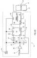
- FIG. 2 aa schematic diagram of apparatus for handling a charging state and/or a device suspend state in a mobile electronic device is shown.
- the apparatusmay, for example, be implemented within the charger interface 14 of FIG. 1 , and includes a battery charger enabling circuit 50 , a battery charger 52 and an inverting circuit 54 .
- the battery charger enabling circuitis a RS flip flop 50 and the inverting circuit is a field effect transistor (FET) 54 .
- the RS flip flop 50includes an S port 56 , an R port 58 , a Vcc port 60 , a Q port 62 and a Q_bar port 64 .
- the battery charger 52includes a CE_bar port 66 (connected to the Q_bar port 64 ), a Vcc port 68 and a BAT port 70 . Both the RS flip flop 50 and the battery charger 52 are connected to ground 72 .
- a USB VBUS input 74is connected to the S port 56 via a delay 76 and the Vcc ports 60 and 68 of the RS flip flop 50 and the battery charger 52 , respectively.
- the delay 76is implemented with a resistor-capacitor (RC) circuit, but may also be a voltage detector with a pre-set delay, or some other type of delay circuit.
- the delay 76may, for example, be preset for 1 to 5 ms.
- the VBUS input 74is also connected to the R port 58 of the RS flip flop 50 via a resistor 78 and to ground 72 via the resistor 78 and a capacitor 80 .
- the values of the resistor 78 and the capacitor 80may be selected so that they form a 100 ms timer 82 , in accordance with the time allotted by the USB specifications for drawing power from a USB host without receiving an enumeration acknowledgement signal from the USB host. This timer represents the time period within which an acknowledgement of enumeration is expected from the USB host CPU 32 by the system 12 .
- the BAT port 70 of the battery charger 52is connected to the CPU 12 and the rechargeable battery 16 to provide the necessary current/voltage from the VBUS input for both powering the mobile electronic device 10 and for recharging the battery 16 . In the case the battery is not present, there is only current/voltage transmitted to the CPU 12 .
- An output 84 from the CPU 12is connected to the R port 58 of the RS flip flop 50 via the FET 54 .
- the output 84is generally a signal which allows the system to enable or disable the battery charger 52 and to switch between the device charging state and the device suspend state.
- FIG. 2 bis a block diagram of a second example apparatus for handling the charging state/device suspend state in a mobile electronic device. This example is similar to the example shown in FIG. 2 a , except that the inverting circuit is an inverter logic gate 90 .
- FIG. 2 cis a block diagram of a third example apparatus for handling the charging state and/or device suspend state in a mobile electronic device. This example is similar to the examples of FIGS. 2 a and 2 c , except that the inverting circuit is a bipolar transistor 92 .
- FIG. 3a flow diagram showing an example method of handling a device charging state in a mobile electronic device is shown.
- a checkis performed to sense if inputs to the charger interface 14 are in a low state.
- the indicationis that there is no power being transferred to the CPU 12 indicating that the battery 16 is dead or not present.
- the output 84 from the CPU 12is transmitted as a low state signal and there is no voltage at the input 74 .
- the rising edge of the VBUS input 74(supplied by the power source 30 in the USB host 22 ) is sensed (step 100 ) by the Vcc port 60 of the RS flip flop 50 . This step is repeated until the rising edge of the VBUS input 74 is sensed (e.g., when the USB cable is connected between the mobile electronic device 10 and the USB host 22 .)
- USB cable 24is connected between the mobile electronic device 10 and the USB host 22 , power from the USB VBUS input 74 , in the form of a current/voltage, is transmitted from the power source 30 via the USB cable 24 to the mobile electronic device 10 .
- the VBUS input 74 inputmay be seen as a high state signal.
- the input 74is sensed by the Vcc port 60 of the RS flip flop 50 which causes the RS flip flop 50 to be initially powered.
- the USB VBUS input 74also transmits the high signal to the S port 56 of the RS flip flop 50 after passing through the delay 76 .
- the delayallows the RS flip flop 50 to be enabled by the input 74 without interruption by inputs at the S or R port 56 and 58 .
- the high state signal received by the S port 56causes the Q_bar port 64 to transmit a low state signal to the CE_bar port 66 enabling the battery charger 70 (step 102 ).
- the battery charger 70then transmits power, in the form of a current, via the BAT port 70 to the system to power up the mobile electronic device 10 and to the battery 16 to recharge the battery.
- the CPU 12responds to an enumeration request from the USB host CPU 32 via the data lines in the USB cable 24 .
- the timer 82is also enabled (step 104 ) by the VBUS input 74 .
- the timer 82is set to a pre-determined time period (determined by the selection of the resistor and capacitor values), such as 100 ms.
- a checkis then performed to verify that the timer 82 has not expired (step 106 ).
- the capacitor 80charges due to the capacitor being in the series with the resistor 78 .
- the value of the resistor 78 and the capacitor 80 in the timer 82are selected so that the capacitor becomes charged (reaches a high state threshold) after the predetermined time period (e.g., 100 ms.)
- the high state threshold from the voltage on the capacitorcauses the input at the R port 58 to be high which, in turn causes the Q_bar port 64 to transmit a high signal to the CE_bar port 66 to disable the battery charger 52 (step 108 ).
- Thisperforms the function of a watchdog timer which verifies that enumeration between the system and the USB host has been acknowledged during the predetermined time period. The device then returns to the step of sensing the rising edge of the VBUS input (step 100 ).
- a checkis performed to determine if enumeration between the system 12 and the USB host CPU 30 has been acknowledged (step 110 ). That is, a check is performed to verify whether or not the CPU 12 has received acknowledgement from the USB host to draw current from the power source 30 . If enumeration has not been acknowledged, verification that the timer has not elapsed is once again performed (step 106 ).
- the systeme.g., CPU 12 transmits a high state signal 84 to the inverting means, seen as the FET 54 in the preferred embodiment, which then sends a low state signal to the R port 58 of the RS flip flop 50 causing the battery charger 52 to remain enabled and the mobile electronic device 10 to enter the device charging state (step 112 ).
- This output 84also overrides the charging of the capacitor 80 by short circuiting the capacitor so that the battery charger 52 is not erroneously disabled after the predetermined time period.
- the output 84 from the system (e.g., CPU) 12is driven to a low state signal which turns off FET 54 allowing resistor 78 to charge capacitor 80 , both inside timer circuit 82 .
- capacitor 80reaches the high state threshold of port R 58 , this causes the RS flip-flop to reset and transmit a high state signal from the Q_bar port 64 to the CE_bar port 66 disabling the battery charger 52 . Since the battery charger 52 is providing power to the system 12 when the battery 16 is dead or not present, the system (e.g., CPU) 12 is powered down and the VBUS current from the VBUS input drops below 500 ⁇ A as required by USB suspend state specifications.
Landscapes
- Engineering & Computer Science (AREA)
- Theoretical Computer Science (AREA)
- General Engineering & Computer Science (AREA)
- Power Engineering (AREA)
- Physics & Mathematics (AREA)
- General Physics & Mathematics (AREA)
- Computer Hardware Design (AREA)
- Charge And Discharge Circuits For Batteries Or The Like (AREA)
- Power Sources (AREA)
Abstract
Description
Claims (13)
Priority Applications (2)
| Application Number | Priority Date | Filing Date | Title |
|---|---|---|---|
| US11/026,443US7663338B2 (en) | 2004-02-17 | 2004-12-30 | Method and apparatus for handling a charging state in a mobile electronic device |
| US12/650,245US8111040B2 (en) | 2004-02-17 | 2009-12-30 | Method and apparatus for handling a charging state in a mobile electronic device |
Applications Claiming Priority (2)
| Application Number | Priority Date | Filing Date | Title |
|---|---|---|---|
| US54543404P | 2004-02-17 | 2004-02-17 | |
| US11/026,443US7663338B2 (en) | 2004-02-17 | 2004-12-30 | Method and apparatus for handling a charging state in a mobile electronic device |
Related Child Applications (1)
| Application Number | Title | Priority Date | Filing Date |
|---|---|---|---|
| US12/650,245ContinuationUS8111040B2 (en) | 2004-02-17 | 2009-12-30 | Method and apparatus for handling a charging state in a mobile electronic device |
Publications (2)
| Publication Number | Publication Date |
|---|---|
| US20050189908A1 US20050189908A1 (en) | 2005-09-01 |
| US7663338B2true US7663338B2 (en) | 2010-02-16 |
Family
ID=34860522
Family Applications (2)
| Application Number | Title | Priority Date | Filing Date |
|---|---|---|---|
| US11/026,443Active2028-02-09US7663338B2 (en) | 2004-02-17 | 2004-12-30 | Method and apparatus for handling a charging state in a mobile electronic device |
| US12/650,245Expired - LifetimeUS8111040B2 (en) | 2004-02-17 | 2009-12-30 | Method and apparatus for handling a charging state in a mobile electronic device |
Family Applications After (1)
| Application Number | Title | Priority Date | Filing Date |
|---|---|---|---|
| US12/650,245Expired - LifetimeUS8111040B2 (en) | 2004-02-17 | 2009-12-30 | Method and apparatus for handling a charging state in a mobile electronic device |
Country Status (5)
| Country | Link |
|---|---|
| US (2) | US7663338B2 (en) |
| EP (3) | EP2482166A1 (en) |
| CA (1) | CA2556442C (en) |
| ES (1) | ES2718534T3 (en) |
| WO (1) | WO2005078554A1 (en) |
Cited By (7)
| Publication number | Priority date | Publication date | Assignee | Title |
|---|---|---|---|---|
| US20090200989A1 (en)* | 2003-05-27 | 2009-08-13 | Research In Motion Limited | Method and Apparatus for Handling a Charging State in a Mobile Electronic Device |
| US20100102774A1 (en)* | 2004-02-17 | 2010-04-29 | Research In Motion Limited | Method and Apparatus for Handling a Charging State in a Mobile Electronic Device |
| US20100117595A1 (en)* | 2004-02-17 | 2010-05-13 | Research In Motion Limited | Method and Apparatus for Handling a Charging State in a Mobile Electronic Device |
| US20150346794A1 (en)* | 2014-05-28 | 2015-12-03 | Seiko Epson Corporation | Electronic device |
| US11102340B2 (en) | 2015-04-03 | 2021-08-24 | Pinn, Inc. | Mobile system with wireless earbud |
| US20220094175A1 (en)* | 2016-01-05 | 2022-03-24 | Guangdong Oppo Mobile Telecommunications Corp., Ltd. | Quick Charging Method, Mobile Terminal, and Power Adapter |
| US11374412B2 (en) | 2017-04-14 | 2022-06-28 | Parker House Mfg. Co., Inc. | Furniture power management system |
Families Citing this family (18)
| Publication number | Priority date | Publication date | Assignee | Title |
|---|---|---|---|---|
| US7711039B2 (en)* | 2005-04-01 | 2010-05-04 | Freescale Semiconductor, Inc. | System and method for protecting low voltage transceiver |
| JP2007068333A (en)* | 2005-08-31 | 2007-03-15 | Sony Corp | Power supply-dedicated device, terminal, power supply system, and power supply method |
| JP5812502B2 (en)* | 2010-08-24 | 2015-11-17 | マーベル ワールド トレード リミテッド | Device interface and apparatus |
| US20120324540A1 (en)* | 2010-11-16 | 2012-12-20 | Flextronics Ap, Llc | System and method for the interoperability of personal electrical appliances |
| WO2012068308A1 (en) | 2010-11-16 | 2012-05-24 | Imerj LLC | Dual screen folding display hinge |
| US8612518B2 (en)* | 2010-11-16 | 2013-12-17 | Maples Corporate Services Limited | Dual screen PC |
| US8926111B2 (en) | 2010-12-17 | 2015-01-06 | Flextronics Ap, Llc | Keyboard lighting device |
| US20140008093A1 (en)* | 2012-07-06 | 2014-01-09 | Robert Bosch Gmbh | Cordless power tool with usb charging |
| JP6288913B2 (en)* | 2012-12-28 | 2018-03-07 | キヤノン株式会社 | Electronic device and program |
| CN104345855B (en)* | 2013-08-05 | 2017-11-24 | 山东比特智能科技股份有限公司 | Current-limiting circuit for USB interface |
| JP6364991B2 (en)* | 2014-06-19 | 2018-08-01 | セイコーエプソン株式会社 | Electronics |
| JP6532357B2 (en)* | 2015-08-31 | 2019-06-19 | キヤノン株式会社 | Power transmission device, control method and program |
| US10409755B2 (en)* | 2016-06-29 | 2019-09-10 | Square, Inc. | Multi-mode USB interface |
| US9710037B1 (en)* | 2016-06-29 | 2017-07-18 | Square, Inc. | USB voltage regulation and switching |
| US10740740B1 (en) | 2016-06-29 | 2020-08-11 | Square, Inc. | Monitoring and recovery for a USB interface |
| WO2018095179A1 (en)* | 2016-11-24 | 2018-05-31 | 天地融科技股份有限公司 | Data transmission method and terminal |
| TWI602382B (en)* | 2017-03-31 | 2017-10-11 | 台達電子工業股份有限公司 | Intelligent uninterruptible power charging apparatus and method of operating the same |
| EP4238703A1 (en)* | 2022-03-01 | 2023-09-06 | Hilti Aktiengesellschaft | Machine tool with integrated battery |
Citations (9)
| Publication number | Priority date | Publication date | Assignee | Title |
|---|---|---|---|---|
| US6211647B1 (en)* | 1999-01-27 | 2001-04-03 | Telefonaktiebolaget Lm Ericsson | Method enabling communications between an electronic device and a battery, an apparatus comprising an electronic device and a battery, and a battery enabling communication |
| US6531845B2 (en)* | 2000-05-26 | 2003-03-11 | Nokia Mobile Phones Limited | Battery charging |
| US6531854B2 (en) | 2001-03-30 | 2003-03-11 | Champion Microelectronic Corp. | Power factor correction circuit arrangement |
| US20030052547A1 (en) | 2001-03-01 | 2003-03-20 | Fischer Daniel M. | Multifunctional charger system and method |
| US20030054703A1 (en) | 2001-03-01 | 2003-03-20 | Fischer Daniel M. | System and method for powering and charging a mobile communication device |
| US20030076138A1 (en) | 2001-10-22 | 2003-04-24 | Winbond Electronics Corporation | Power-on circuit of a peripheral component |
| US6633932B1 (en) | 1999-09-14 | 2003-10-14 | Texas Instruments Incorporated | Method and apparatus for using a universal serial bus to provide power to a portable electronic device |
| US20040239294A1 (en) | 2003-05-27 | 2004-12-02 | Dusan Veselic | Method and apparatus for handling a charging state in a mobile electronic device |
| US20040251878A1 (en) | 2003-06-11 | 2004-12-16 | Dusan Veselic | Universal Serial bus charger for a mobile device |
Family Cites Families (32)
| Publication number | Priority date | Publication date | Assignee | Title |
|---|---|---|---|---|
| US3748386A (en)* | 1972-04-03 | 1973-07-24 | D Monney | Time-base error correction system |
| US4568096A (en)* | 1984-04-19 | 1986-02-04 | General Motors Corporation | Automatic vehicle level control |
| US5398265A (en)* | 1988-11-10 | 1995-03-14 | Hughes Aircraft Company | Computer subsystem reset by address dependent RC discharge |
| US5028859A (en)* | 1989-06-05 | 1991-07-02 | Motorola, Inc. | Multiple battery, multiple rate battery charger |
| US5250891A (en)* | 1991-05-13 | 1993-10-05 | Milwaukee Electric Tool Corporation | Battery charging method and apparatus |
| JP2959657B2 (en)* | 1993-05-13 | 1999-10-06 | キヤノン株式会社 | Electronics |
| US6101421A (en)* | 1993-09-10 | 2000-08-08 | Motorola, Inc. | Reset recovery in a microprocessor controlled device |
| US5519346A (en)* | 1994-06-22 | 1996-05-21 | Motorola, Inc. | Selective restart circuit for an electronic device |
| JP3733554B2 (en)* | 1994-10-31 | 2006-01-11 | 富士通株式会社 | Battery-powered electronic equipment |
| GB9623612D0 (en)* | 1996-11-13 | 1997-01-08 | Rca Thomson Licensing Corp | Separate power supplies for standby operation |
| US6357011B2 (en)* | 1998-07-15 | 2002-03-12 | Gateway, Inc. | Bus-powered computer peripheral with supplement battery power to overcome bus-power limit |
| JP2000105638A (en)* | 1998-09-29 | 2000-04-11 | Nec Corp | Usb device and usb connection system |
| US6211649B1 (en)* | 1999-03-25 | 2001-04-03 | Sourcenext Corporation | USB cable and method for charging battery of external apparatus by using USB cable |
| US6031362A (en)* | 1999-05-13 | 2000-02-29 | Bradley; Larry D. | Method and apparatus for feedback control of switch mode power supply output to linear regulators |
| US6153855A (en)* | 1999-05-20 | 2000-11-28 | Illinois Tool Works Inc. | Control of weld and auxiliary power output of a generator type welding power supply |
| DE19944053C2 (en) | 1999-09-14 | 2001-08-02 | Infineon Technologies Ag | Device and method for the power supply of computer accessories via the bus system of the computer |
| US6665801B1 (en)* | 2000-01-27 | 2003-12-16 | Symbol Technologies, Inc. | Method and apparatus for charging a self powered USB device at different charge rates according to the charge level of a rechargeable element on the device |
| TW479393B (en)* | 2000-09-27 | 2002-03-11 | Acer Peripherals Inc | Automatic USB charging apparatus and its operating method |
| US6883715B1 (en)* | 2000-10-11 | 2005-04-26 | Stmicroelectronics, Inc. | Multi-mode smart card, system and associated methods |
| EP1198049A1 (en) | 2000-10-12 | 2002-04-17 | Sony International (Europe) GmbH | Charging circuit for charging a mobile terminal through an USB interface |
| WO2002071734A2 (en)* | 2000-12-19 | 2002-09-12 | Smal Camera Technologies, Inc. | Compact digital camera system |
| US6507172B2 (en)* | 2001-03-19 | 2003-01-14 | Maxim Integrated Products, Inc. | Universal serial bus powered battery charger |
| US6853259B2 (en)* | 2001-08-15 | 2005-02-08 | Gallitzin Allegheny Llc | Ring oscillator dynamic adjustments for auto calibration |
| US6812971B2 (en)* | 2001-09-11 | 2004-11-02 | Olympus Optical Co., Ltd. | Electronic apparatus, stand and electronic apparatus stand system |
| US20030110403A1 (en)* | 2001-12-10 | 2003-06-12 | Intel Corporation | System for shared power supply in computer peripheral devices |
| TW543994U (en)* | 2001-12-25 | 2003-07-21 | Sheng-Shing Liau | Easy carrying multi-function charger |
| JP3904489B2 (en)* | 2002-07-04 | 2007-04-11 | 富士通株式会社 | Charge control circuit, charger, power supply circuit, information processing apparatus, and battery pack |
| JP3654274B2 (en)* | 2002-08-30 | 2005-06-02 | セイコーエプソン株式会社 | Data transfer control device, electronic device, and power supply switching method |
| US6650089B1 (en)* | 2002-10-16 | 2003-11-18 | Texas Instruments Incorporated | Control circuit for multiple battery systems with capacity gauge on end equipment |
| US6833686B2 (en)* | 2003-02-21 | 2004-12-21 | Research In Motion Limited | Circuit and method of operation for an adaptive charge rate power supply |
| CA2556442C (en) | 2004-02-17 | 2011-02-01 | Research In Motion Limited | Method and apparatus for handling a charging state in a mobile electronic device |
| EP1723494A4 (en)* | 2004-02-17 | 2010-09-29 | Research In Motion Ltd | Method and apparatus for handling a charging state in a mobile electronic device |
- 2004
- 2004-12-30CACA2556442Apatent/CA2556442C/ennot_activeExpired - Lifetime
- 2004-12-30EPEP12165825Apatent/EP2482166A1/ennot_activeWithdrawn
- 2004-12-30USUS11/026,443patent/US7663338B2/enactiveActive
- 2004-12-30EPEP14182671.9Apatent/EP2808755B1/ennot_activeExpired - Lifetime
- 2004-12-30WOPCT/CA2004/002208patent/WO2005078554A1/enactiveApplication Filing
- 2004-12-30ESES14182671Tpatent/ES2718534T3/ennot_activeExpired - Lifetime
- 2004-12-30EPEP04802383.2Apatent/EP1723493B1/ennot_activeExpired - Lifetime
- 2009
- 2009-12-30USUS12/650,245patent/US8111040B2/ennot_activeExpired - Lifetime
Patent Citations (9)
| Publication number | Priority date | Publication date | Assignee | Title |
|---|---|---|---|---|
| US6211647B1 (en)* | 1999-01-27 | 2001-04-03 | Telefonaktiebolaget Lm Ericsson | Method enabling communications between an electronic device and a battery, an apparatus comprising an electronic device and a battery, and a battery enabling communication |
| US6633932B1 (en) | 1999-09-14 | 2003-10-14 | Texas Instruments Incorporated | Method and apparatus for using a universal serial bus to provide power to a portable electronic device |
| US6531845B2 (en)* | 2000-05-26 | 2003-03-11 | Nokia Mobile Phones Limited | Battery charging |
| US20030052547A1 (en) | 2001-03-01 | 2003-03-20 | Fischer Daniel M. | Multifunctional charger system and method |
| US20030054703A1 (en) | 2001-03-01 | 2003-03-20 | Fischer Daniel M. | System and method for powering and charging a mobile communication device |
| US6531854B2 (en) | 2001-03-30 | 2003-03-11 | Champion Microelectronic Corp. | Power factor correction circuit arrangement |
| US20030076138A1 (en) | 2001-10-22 | 2003-04-24 | Winbond Electronics Corporation | Power-on circuit of a peripheral component |
| US20040239294A1 (en) | 2003-05-27 | 2004-12-02 | Dusan Veselic | Method and apparatus for handling a charging state in a mobile electronic device |
| US20040251878A1 (en) | 2003-06-11 | 2004-12-16 | Dusan Veselic | Universal Serial bus charger for a mobile device |
Cited By (17)
| Publication number | Priority date | Publication date | Assignee | Title |
|---|---|---|---|---|
| US20110140674A1 (en)* | 2003-05-27 | 2011-06-16 | Research In Motion Limited | Method and Apparatus for Handling a Charging State in a Mobile Electronic Device |
| US8610407B2 (en) | 2003-05-27 | 2013-12-17 | Blackberry Limited | Method and apparatus for handling a charging state in a mobile electronic device |
| US8283897B2 (en) | 2003-05-27 | 2012-10-09 | Research In Motion Limited | Method and apparatus for handling a charging state in a mobile electronic device |
| US7768239B2 (en) | 2003-05-27 | 2010-08-03 | Research In Motion Limited | Method and apparatus for handling a charging state in a mobile electronic device |
| US20100289456A1 (en)* | 2003-05-27 | 2010-11-18 | Research In Motion Limited | Method and Apparatus for Handling a Charging State in a Mobile Electronic Device |
| US20090200989A1 (en)* | 2003-05-27 | 2009-08-13 | Research In Motion Limited | Method and Apparatus for Handling a Charging State in a Mobile Electronic Device |
| US7893660B2 (en) | 2003-05-27 | 2011-02-22 | Research In Motion Limited | Method and apparatus for handling a charging state in a mobile electronic device |
| US8111040B2 (en)* | 2004-02-17 | 2012-02-07 | Research In Motion Limited | Method and apparatus for handling a charging state in a mobile electronic device |
| US7847517B2 (en) | 2004-02-17 | 2010-12-07 | Research In Motion Limited | Method and apparatus for handling a charging state in a mobile electronic device |
| US20100117595A1 (en)* | 2004-02-17 | 2010-05-13 | Research In Motion Limited | Method and Apparatus for Handling a Charging State in a Mobile Electronic Device |
| US20100102774A1 (en)* | 2004-02-17 | 2010-04-29 | Research In Motion Limited | Method and Apparatus for Handling a Charging State in a Mobile Electronic Device |
| US20150346794A1 (en)* | 2014-05-28 | 2015-12-03 | Seiko Epson Corporation | Electronic device |
| US9665150B2 (en)* | 2014-05-28 | 2017-05-30 | Seiko Epson Corporation | Electronic device with a control circuit to detect and establish a connection to host device |
| US11102340B2 (en) | 2015-04-03 | 2021-08-24 | Pinn, Inc. | Mobile system with wireless earbud |
| US20220094175A1 (en)* | 2016-01-05 | 2022-03-24 | Guangdong Oppo Mobile Telecommunications Corp., Ltd. | Quick Charging Method, Mobile Terminal, and Power Adapter |
| US11791651B2 (en)* | 2016-01-05 | 2023-10-17 | Guangdong Oppo Mobile Telecommunications Corp., Ltd. | Quick charging method, mobile terminal, and power adapter |
| US11374412B2 (en) | 2017-04-14 | 2022-06-28 | Parker House Mfg. Co., Inc. | Furniture power management system |
Also Published As
| Publication number | Publication date |
|---|---|
| CA2556442C (en) | 2011-02-01 |
| US20100102774A1 (en) | 2010-04-29 |
| US8111040B2 (en) | 2012-02-07 |
| EP1723493B1 (en) | 2014-10-29 |
| EP2808755B1 (en) | 2019-03-06 |
| US20050189908A1 (en) | 2005-09-01 |
| EP1723493A4 (en) | 2010-03-10 |
| CA2556442A1 (en) | 2005-08-25 |
| HK1094049A1 (en) | 2007-03-16 |
| EP1723493A1 (en) | 2006-11-22 |
| ES2718534T3 (en) | 2019-07-02 |
| EP2482166A1 (en) | 2012-08-01 |
| WO2005078554A1 (en) | 2005-08-25 |
| HK1206826A1 (en) | 2016-01-15 |
| EP2808755A1 (en) | 2014-12-03 |
Similar Documents
| Publication | Publication Date | Title |
|---|---|---|
| US8111040B2 (en) | Method and apparatus for handling a charging state in a mobile electronic device | |
| US8610407B2 (en) | Method and apparatus for handling a charging state in a mobile electronic device | |
| US7679316B2 (en) | Method and apparatus for controlling a charging state in a mobile electronic device | |
| US8648573B2 (en) | Charger and portable device having the same | |
| HK1206826B (en) | Method and apparatus for handling a charging state in a mobile electronic device | |
| HK1094049B (en) | Method and apparatus for handling a charging state in a mobile electronic device | |
| HK1071234B (en) | Method and apparatus for controlling the charging state in a mobile electronic device |
Legal Events
| Date | Code | Title | Description |
|---|---|---|---|
| AS | Assignment | Owner name:RESEARCH IN MOTION LIMITED, CANADA Free format text:ASSIGNMENT OF ASSIGNORS INTEREST;ASSIGNORS:GUTHRIE, MARTIN G. A.;VESELIC, DUSAN;SKARINE, ALEXEI;AND OTHERS;REEL/FRAME:015605/0526 Effective date:20041217 Owner name:RESEARCH IN MOTION LIMITED,CANADA Free format text:ASSIGNMENT OF ASSIGNORS INTEREST;ASSIGNORS:GUTHRIE, MARTIN G. A.;VESELIC, DUSAN;SKARINE, ALEXEI;AND OTHERS;REEL/FRAME:015605/0526 Effective date:20041217 | |
| STCF | Information on status: patent grant | Free format text:PATENTED CASE | |
| CC | Certificate of correction | ||
| FPAY | Fee payment | Year of fee payment:4 | |
| AS | Assignment | Owner name:BLACKBERRY LIMITED, ONTARIO Free format text:CHANGE OF NAME;ASSIGNOR:RESEARCH IN MOTION LIMITED;REEL/FRAME:036356/0472 Effective date:20130709 | |
| AS | Assignment | Owner name:FUNDAMENTAL INNOVATION SYSTEMS INTERNATIONAL LLC, Free format text:ASSIGNMENT OF ASSIGNORS INTEREST;ASSIGNOR:BLACKBERRY LIMITED;REEL/FRAME:037324/0978 Effective date:20151119 | |
| AS | Assignment | Owner name:FUNDAMENTAL INNOVATION SYSTEMS INTERNATIONAL LLC, Free format text:ASSIGNMENT OF ASSIGNORS INTEREST;ASSIGNOR:BLACKBERRY LIMITED;REEL/FRAME:040792/0483 Effective date:20151118 | |
| FPAY | Fee payment | Year of fee payment:8 | |
| MAFP | Maintenance fee payment | Free format text:PAYMENT OF MAINTENANCE FEE, 12TH YEAR, LARGE ENTITY (ORIGINAL EVENT CODE: M1553); ENTITY STATUS OF PATENT OWNER: LARGE ENTITY Year of fee payment:12 |