US7662133B2 - Spinal fluid introduction - Google Patents
Spinal fluid introductionDownload PDFInfo
- Publication number
- US7662133B2 US7662133B2US10/782,900US78290004AUS7662133B2US 7662133 B2US7662133 B2US 7662133B2US 78290004 AUS78290004 AUS 78290004AUS 7662133 B2US7662133 B2US 7662133B2
- Authority
- US
- United States
- Prior art keywords
- fluid
- introducer
- fluid introduction
- data
- patient
- Prior art date
- Legal status (The legal status is an assumption and is not a legal conclusion. Google has not performed a legal analysis and makes no representation as to the accuracy of the status listed.)
- Expired - Fee Related, expires
Links
- 239000012530fluidSubstances0.000titleclaimsabstractdescription372
- 230000004044responseEffects0.000claimsabstractdescription58
- 208000002193PainDiseases0.000claimsdescription74
- 230000036407painEffects0.000claimsdescription72
- 208000024891symptomDiseases0.000claimsdescription17
- 230000001419dependent effectEffects0.000claimsdescription14
- 238000003745diagnosisMethods0.000claimsdescription9
- 230000002596correlated effectEffects0.000claimsdescription7
- 238000005259measurementMethods0.000claimsdescription4
- 230000000541pulsatile effectEffects0.000claimsdescription4
- 230000001815facial effectEffects0.000claimsdescription2
- 238000003780insertionMethods0.000claims7
- 230000037431insertionEffects0.000claims7
- 230000013011matingEffects0.000claims3
- 238000000034methodMethods0.000abstractdescription19
- 230000000712assemblyEffects0.000description10
- 238000000429assemblyMethods0.000description10
- 208000008035Back PainDiseases0.000description9
- 238000005336crackingMethods0.000description9
- 238000012360testing methodMethods0.000description9
- 238000002347injectionMethods0.000description6
- 239000007924injectionSubstances0.000description6
- 238000012544monitoring processMethods0.000description6
- 238000004891communicationMethods0.000description5
- 239000003550markerSubstances0.000description4
- 210000005036nerveAnatomy0.000description4
- 206010033425Pain in extremityDiseases0.000description3
- 239000002639bone cementSubstances0.000description3
- 230000000638stimulationEffects0.000description3
- 230000002123temporal effectEffects0.000description3
- FAPWRFPIFSIZLT-UHFFFAOYSA-MSodium chlorideChemical compound[Na+].[Cl-]FAPWRFPIFSIZLT-UHFFFAOYSA-M0.000description2
- 230000003416augmentationEffects0.000description2
- 239000002872contrast mediaSubstances0.000description2
- 230000007423decreaseEffects0.000description2
- 238000002405diagnostic procedureMethods0.000description2
- 238000003384imaging methodMethods0.000description2
- 238000007726management methodMethods0.000description2
- 238000002559palpationMethods0.000description2
- 238000003825pressingMethods0.000description2
- 208000000094Chronic PainDiseases0.000description1
- 102000004127CytokinesHuman genes0.000description1
- 108090000695CytokinesProteins0.000description1
- 206010061991GrimacingDiseases0.000description1
- 102000015696InterleukinsHuman genes0.000description1
- 108010063738InterleukinsProteins0.000description1
- 102100037611LysophospholipaseHuman genes0.000description1
- 108010058864Phospholipases A2Proteins0.000description1
- 206010059604Radicular painDiseases0.000description1
- 108700012920TNFProteins0.000description1
- 239000000853adhesiveSubstances0.000description1
- 230000001070adhesive effectEffects0.000description1
- 230000036592analgesiaEffects0.000description1
- 210000003484anatomyAnatomy0.000description1
- 239000003242anti bacterial agentSubstances0.000description1
- 229910052788bariumInorganic materials0.000description1
- DSAJWYNOEDNPEQ-UHFFFAOYSA-Nbarium atomChemical compound[Ba]DSAJWYNOEDNPEQ-UHFFFAOYSA-N0.000description1
- 230000003115biocidal effectEffects0.000description1
- 210000001217buttockAnatomy0.000description1
- 230000008859changeEffects0.000description1
- 230000000295complement effectEffects0.000description1
- 238000002591computed tomographyMethods0.000description1
- 239000004020conductorSubstances0.000description1
- 238000012937correctionMethods0.000description1
- 230000003412degenerative effectEffects0.000description1
- 239000007857degradation productSubstances0.000description1
- 238000013461designMethods0.000description1
- 238000012774diagnostic algorithmMethods0.000description1
- -1e.g.Polymers0.000description1
- 230000000694effectsEffects0.000description1
- 230000000763evoking effectEffects0.000description1
- 238000002594fluoroscopyMethods0.000description1
- 239000000017hydrogelSubstances0.000description1
- 230000006872improvementEffects0.000description1
- 208000015181infectious diseaseDiseases0.000description1
- 230000000977initiatory effectEffects0.000description1
- 230000003993interactionEffects0.000description1
- 229940047122interleukinsDrugs0.000description1
- 238000002955isolationMethods0.000description1
- 239000007788liquidSubstances0.000description1
- 238000002595magnetic resonance imagingMethods0.000description1
- 238000004519manufacturing processMethods0.000description1
- 239000000463materialSubstances0.000description1
- 239000000203mixtureSubstances0.000description1
- 210000004126nerve fiberAnatomy0.000description1
- 230000001473noxious effectEffects0.000description1
- 230000007170pathologyEffects0.000description1
- 229920003229poly(methyl methacrylate)Polymers0.000description1
- 229920000642polymerPolymers0.000description1
- 239000004926polymethyl methacrylateSubstances0.000description1
- 239000000843powderSubstances0.000description1
- 230000008569processEffects0.000description1
- 239000012858resilient materialSubstances0.000description1
- 230000026416response to painEffects0.000description1
- 230000002441reversible effectEffects0.000description1
- 239000002210silicon-based materialSubstances0.000description1
- 238000011282treatmentMethods0.000description1
- 210000000689upper legAnatomy0.000description1
- 230000000007visual effectEffects0.000description1
Images


Classifications
- A—HUMAN NECESSITIES
- A61—MEDICAL OR VETERINARY SCIENCE; HYGIENE
- A61M—DEVICES FOR INTRODUCING MEDIA INTO, OR ONTO, THE BODY; DEVICES FOR TRANSDUCING BODY MEDIA OR FOR TAKING MEDIA FROM THE BODY; DEVICES FOR PRODUCING OR ENDING SLEEP OR STUPOR
- A61M5/00—Devices for bringing media into the body in a subcutaneous, intra-vascular or intramuscular way; Accessories therefor, e.g. filling or cleaning devices, arm-rests
- A61M5/14—Infusion devices, e.g. infusing by gravity; Blood infusion; Accessories therefor
- A61M5/142—Pressure infusion, e.g. using pumps
- A61M5/145—Pressure infusion, e.g. using pumps using pressurised reservoirs, e.g. pressurised by means of pistons
- A61M5/1452—Pressure infusion, e.g. using pumps using pressurised reservoirs, e.g. pressurised by means of pistons pressurised by means of pistons
- A61M5/1456—Pressure infusion, e.g. using pumps using pressurised reservoirs, e.g. pressurised by means of pistons pressurised by means of pistons with a replaceable reservoir comprising a piston rod to be moved into the reservoir, e.g. the piston rod is part of the removable reservoir
- A—HUMAN NECESSITIES
- A61—MEDICAL OR VETERINARY SCIENCE; HYGIENE
- A61B—DIAGNOSIS; SURGERY; IDENTIFICATION
- A61B17/00—Surgical instruments, devices or methods
- A61B17/34—Trocars; Puncturing needles
- A61B17/3401—Puncturing needles for the peridural or subarachnoid space or the plexus, e.g. for anaesthesia
- A—HUMAN NECESSITIES
- A61—MEDICAL OR VETERINARY SCIENCE; HYGIENE
- A61B—DIAGNOSIS; SURGERY; IDENTIFICATION
- A61B17/00—Surgical instruments, devices or methods
- A61B17/56—Surgical instruments or methods for treatment of bones or joints; Devices specially adapted therefor
- A61B17/58—Surgical instruments or methods for treatment of bones or joints; Devices specially adapted therefor for osteosynthesis, e.g. bone plates, screws or setting implements
- A61B17/88—Osteosynthesis instruments; Methods or means for implanting or extracting internal or external fixation devices
- A61B17/8802—Equipment for handling bone cement or other fluid fillers
- A61B17/8805—Equipment for handling bone cement or other fluid fillers for introducing fluid filler into bone or extracting it
- A61B17/8822—Equipment for handling bone cement or other fluid fillers for introducing fluid filler into bone or extracting it characterised by means facilitating expulsion of fluid from the introducer, e.g. a screw pump plunger, hydraulic force transmissions, application of vibrations or a vacuum
- A—HUMAN NECESSITIES
- A61—MEDICAL OR VETERINARY SCIENCE; HYGIENE
- A61M—DEVICES FOR INTRODUCING MEDIA INTO, OR ONTO, THE BODY; DEVICES FOR TRANSDUCING BODY MEDIA OR FOR TAKING MEDIA FROM THE BODY; DEVICES FOR PRODUCING OR ENDING SLEEP OR STUPOR
- A61M5/00—Devices for bringing media into the body in a subcutaneous, intra-vascular or intramuscular way; Accessories therefor, e.g. filling or cleaning devices, arm-rests
- A61M5/14—Infusion devices, e.g. infusing by gravity; Blood infusion; Accessories therefor
- A61M5/168—Means for controlling media flow to the body or for metering media to the body, e.g. drip meters, counters ; Monitoring media flow to the body
- A61M5/16831—Monitoring, detecting, signalling or eliminating infusion flow anomalies
- A61M5/16854—Monitoring, detecting, signalling or eliminating infusion flow anomalies by monitoring line pressure
- A—HUMAN NECESSITIES
- A61—MEDICAL OR VETERINARY SCIENCE; HYGIENE
- A61M—DEVICES FOR INTRODUCING MEDIA INTO, OR ONTO, THE BODY; DEVICES FOR TRANSDUCING BODY MEDIA OR FOR TAKING MEDIA FROM THE BODY; DEVICES FOR PRODUCING OR ENDING SLEEP OR STUPOR
- A61M25/00—Catheters; Hollow probes
- A61M2025/0007—Epidural catheters
- A—HUMAN NECESSITIES
- A61—MEDICAL OR VETERINARY SCIENCE; HYGIENE
- A61M—DEVICES FOR INTRODUCING MEDIA INTO, OR ONTO, THE BODY; DEVICES FOR TRANSDUCING BODY MEDIA OR FOR TAKING MEDIA FROM THE BODY; DEVICES FOR PRODUCING OR ENDING SLEEP OR STUPOR
- A61M2205/00—General characteristics of the apparatus
- A61M2205/33—Controlling, regulating or measuring
- A61M2205/3331—Pressure; Flow
- A—HUMAN NECESSITIES
- A61—MEDICAL OR VETERINARY SCIENCE; HYGIENE
- A61M—DEVICES FOR INTRODUCING MEDIA INTO, OR ONTO, THE BODY; DEVICES FOR TRANSDUCING BODY MEDIA OR FOR TAKING MEDIA FROM THE BODY; DEVICES FOR PRODUCING OR ENDING SLEEP OR STUPOR
- A61M5/00—Devices for bringing media into the body in a subcutaneous, intra-vascular or intramuscular way; Accessories therefor, e.g. filling or cleaning devices, arm-rests
- A61M5/14—Infusion devices, e.g. infusing by gravity; Blood infusion; Accessories therefor
- A61M5/168—Means for controlling media flow to the body or for metering media to the body, e.g. drip meters, counters ; Monitoring media flow to the body
- A61M5/16804—Flow controllers
- A61M5/16827—Flow controllers controlling delivery of multiple fluids, e.g. sequencing, mixing or via separate flow-paths
Definitions
- the present inventionrelates to a system and method for introducing fluid into a spine.
- Back painis a common problem and is difficult to treat. Because of the complex anatomy and poor correlation of pathology and symptoms, diagnosis of the etiology of the pain may be difficult. Typical diagnostic procedures seek to determine whether a patient experiences back pain, leg pain, or a combination thereof. Back pain describes pain localized to the back, and often includes pain in the buttocks and upper thigh areas. This type of pain is understood to be caused by changes in one or more intervertebral discs and is termed discogenic back pain.
- discsare potential pain sources has been a relatively recent discovery and is supported by anatomical studies that demonstrate nerve fibers within the disc, often increased by degenerative processes, and by direct stimulation of discs during discectomy procedures while the patient is under aware-state analgesia. Other causes of back pain have also been described including zygopophyseal (facet) joints, and other unknown causes.
- leg painis often due to impingement of nerve roots as they exit the spinal canal. This causes pain to radiate into the areas the nerves innervate and creates a dermatomal pattern of pain related to the normal pattern of the nerve supply.
- This radicular painis often due to herniation of intervertebral discs such that they bulge into the foramenal space, entrapping and pressing on the nerve. It is also believed to result from nucleus pulposus material extruding from the disc, resulting in noxious stimuli from degradation products such as phospholipase A2, and cytokines such as interleukins and TNFa.
- a staple of physical examinationis palpation of the painful region, to pinpoint where the pain is emanating from. This is difficult in the case of the intervertebral disc as it is anatomically located deep within the body and surrounded by bony structures.
- a procedure known as discography, discogram, disc stimulation, or more precisely as provocative discography,has been developed to overcome this limitation.
- Discographyinvolves placing a needle into the intervertebral disc using fluoroscopic guidance and then injecting a fluid to create pressure to stimulate the disc, analogously to palpation.
- the injected fluidis typically a saline solution including radiopaque dye to allow for assessment of the disc morphology.
- a manually operated syringeis generally used to inject the fluid.
- the patientis maintained in an aware state such that they can provide feedback as to the pain induced by the injection, i.e. pressurization of the disc.
- Injectionis performed one disc level at a time with the injectionist, e.g., a physician, switching connections prior to the start of the test at a specific level.
- Pressure manometryhas been used to monitor the pressure applied to the disc. This provides a more objective means for the injectionist to control pressure as compared to determining the pressure based upon the feel of a manually operated syringe. Studies have demonstrated a better diagnostic correlation when patients respond to low to moderate pressures ( ⁇ 50 psi) as compared to higher pressures (>50 psi).
- a patient's response to paincan include two components: the magnitude of pain and the quality of pain.
- the magnitudeis often described as ranging from 0 to 10, where 0 is no pain, and 10 is the worst pain imaginable.
- the quality of painis described as being concordant, meaning the back pain they are complaining of, or not concordant, pain different from their complaint, such as a general feeling of pressure.
- the ability to distinguish between concordant and non-concordant painimproves the determination of whether the disc being stimulated is the root cause of a patient's back pain, or is evoking pain unrelated to their symptoms.
- a low pressure, concordant pain response at 1 or 2 spine levels, e.g., spinal discs, accompanied by no pain at a level above or below (control level) the painful discsis generally understood to provide the most definitive diagnosis for discogenic pain.
- Patient responses from a discography procedureare recorded by the injectionist or assistant using one or more forms. Other parameters, such as the volume of fluid injected are added to the patient responses. A separate chart can be used to determine the peak pressure in the disc as well as any leakage.
- the fluid introduction systemincludes wan introducer configured to create a pressure of at least 10 psi (69 kPa) within a spine, and an operator configured to actuate the introducer to introduce fluid into the spine according to a predetermined fluid introduction profile.
- the introducercan be configured to create a pressure of at least 10 psi (69 kPa) in an intervertebral disc.
- the predetermined fluid introduction profilecan be the introduction of fluid at a constant rate.
- the introducercan be configured to introduce a repeatable amount of fluid into the spine.
- the introducercan be configured to introduce fluid into the spine at a repeatable rate.
- the introducercan be configured to introduce a non-pulsatile flow of fluid into the spine.
- the introducercan be configured to create a pressure of at least 20 psi (138 kPa) in an intervertebral disc.
- a fluid introduction systemcomprises an introducer configured to introduce fluid into a spine of a patient, an operator configured to actuate the introducer to introduce fluid into the spine of the patient, a computer readable medium having code for receiving fluid introduction data indicative of a fluid introduction parameter, and for receiving response data indicative of a response of the patient at a time related to a time of the fluid introduction data.
- the fluid introduction parametercan be a pressure within an intervertebral disc of the patient at the time of the fluid introduction data and/or a total amount of fluid introduced into an intervertebral disc of the patient at the time of the fluid introduction data.
- the fluid introduction parametercan be configured to obtain the response data from an observation of the patient and/or to obtain the response data upon a response by the patient.
- the fluid introducercan be configured to create a pressure of at least 100 kPa within the spine.
- a fluid introduction systemincludes an introducer configured to introduce a non-pulsatile flow of fluid into a spine, and an operator configured to actuate the introducer.
- the introducerhas a flow rate-dependent impedance opposing the introduction of the fluid.
- the operatorincludes code to control the actuation of the introducer based at least in part upon impedance data indicative of the impedance.
- the introducercan include an identifier including the impedance data and the operator can be configured to receive the impedance data from the identifier of the introducer.
- the operatorcan include code to determine the impedance data based upon an actuation of the introducer.
- the fluid introduction systemcan include a pressure sensor configured to provide pressure data indicative of a pressure of fluid present in the introducer, a fluid introduction sensor configured to provide fluid introduction data indicative of at least one of (a) a rate of fluid introduction and (b) an amount of fluid dispensed from the introducer, and the operator can include code to determine the impedance data based upon the pressure data and the fluid introduction data.
- a fluid introduction systemincludes a first introducer configured to introduce fluid into a first portion of a spine, a second introducer configured to introduce fluid into a second, different portion of a spine, and an operator configurable to concurrently actuate the introduction of fluid into the first portion of the spine by the first introducer and the introduction of fluid into the second portion of the spine by the second introducer.
- the first and second introducerscan be respectively configured to introduce fluid into first and second different intervertebral discs, such as to provide a simultaneous pressure of at least 10 psi (69 kPa) in each of the first and second intervertebral discs.
- the first and second introducerscan be actuable independently of one another.
- a fluid introduction systemincludes an introducer configured to introduce a fluid having a dynamic viscosity of at least 750 Pa into a spine and an operator configured to actuate the introducer according to a predetermined introduction profile.
- the fluidcan be at least one of a polymeric fluid and a non-Newtonian fluid.
- the introducercan have an impedance that opposes the actuation of the introducer, the impedance is, e.g., dependent upon the viscosity of the fluid and the fluid introduction system can be configured to obtain impedance data indicative of the dynamic viscosity of the fluid.
- a syringeincludes a reservoir, a plunger slidable with respect to the reservoir to apply pressure to fluid therein, and a pressure transducer secured with respect to the plunger and configured to be in direct contact with fluid in the reservoir.
- a receivable portion of the plungercan be receivable within the reservoir.
- the syringecan include a cap secured with respect to the receivable portion of the plunger.
- the pressure transducercan be disposed between at least a portion of the cap and at least a portion of the receivable portion of the plunger.
- the capcan include a hole configured to allow fluid present within the reservoir to contact the pressure transducer.
- the cap and the plungercan be configured so as not to be rotatable with respect to one another when the cap is secured with respect to the receivable portion of the plunger.
- the cap and the receivable portion of the plungercan each comprise an asymmetrical portion.
- the asymmetrical portions of the cap and plungercan mate with one another to secure the cap with respect to the plunger.
- a fluid introduction systemincludes an introducer configured to introduce a fluid into a spine, and an operator configured to actuate the introducer to introduce fluid into the spine according to a predetermined fluid introduction profile.
- a method for introducing fluidincludes positioning a first introducer in a first portion of a spine, positioning a second introducer in a second, different portion of the spine and, without removing the first and second introducers, introducing fluid into the first portion of the spine with the first introducer and introducing fluid into the second portion of the spine with the second introducer.
- the first and second portions of the spinecan be different intervertebral discs.
- Introducing fluid into the first portion of the spinecan include creating a pressure of at least 10 psi (69 kPa) in the first portion of the spine, and introducing fluid into the second portion of the spine can include creating a pressure of at least 10 psi (69 kPa) in the second portion of the spine.
- Introducing fluid into the first portion of the spinecan at least partially overlap the step of introducing fluid into the second portion of the spine.
- Positioning at least two introducersis advantageous over removing and reinserting a needle because such movement can cause the patient to anticipate pain. Additionally, the present system and method reduces the risk of infection because a syringe need be connected and removed only once during the procedure. Use of multiple introducers decreases the time required to perform a discography diagnostic by reducing the need for switching the injection system between needles, and increases the degree of flexibility for testing and retesting various levels.
- a method and systemhave been developed that improves the overall quality of introduction of fluid into the spine, e.g., during discography, vertebroplasty, and/or nucleus augmentation.
- the improvementincludes the ability to perform the test in a more reproducible manner, improving clinical efficacy.
- the current systemhas design features that allow for a more standardized procedure with regards to patient interaction and feedback on pain responses. This is achieved by having a standardized dialog for the injectionist and patient such that the injectionist does not provide inadvertent cues to the patient that could influence the patient's response, and that instructs the patient concerning their role in the procedure. Properly “blinding” the patient as to when injections are performed is an example of how to avoid responses that could negatively influence the value of the procedure. There is a substantial psychological component of pain, and this appears to be exacerbated in chronic pain sufferers such as many people with back pain.
- a patient interface module of the systemis also an embodiment. This includes a touch panel screen where the patient traces pain as to intensity and quality (concordant or not). Another embodiment is a squeeze bulb for intensity of pain.
- Another aspect of performing a standardized provocative disc diagnosisinvolves management of the data such that a diagnostic report can be generated.
- the system of the current inventionhas a central data logger that correlates pressure, flow and volume readings from a syringe manometry device with the injection sequence and patient response data.
- This central processorfurther performs a diagnostic algorithm such as described by the ISIS (International Spine Injection Society) Guidelines (modified to incorporate the more robust data provided with this enhanced system), such that a diagnostic report is generated.
- the central processorhas user interfaces such as a key board that allows for entry of patient name, age, sex, date, and other key demographic and procedure information such that reporting, billing and other functions are expeditiously performed.
- FIG. 1is a schematic illustration of a fluid introduction system
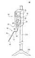
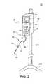
- FIG. 2is an illustration of the fluid introduction system of FIG. 1 ;
- FIG. 3is an illustration of the fluid drive assembly of the fluid introduction system of FIG. 1 ;
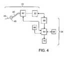
- FIG. 4is an illustration of sub-systems of the fluid introduction system of FIG. 1 ;
- FIGS. 5 and 6are illustrations of flow rate graphs
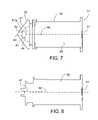
- FIG. 7is a side-view of a plunger and cap with pressure transducer
- FIG. 8is an illustration of the plunger of FIG. 7 with the cap and pressure transducer removed;
- FIG. 9is a front view of the plunger of FIG. 8 ;
- FIG. 10is a rear view of the cap of FIG. 7 with the plunger and pressure transducer removed.
- FIG. 11is a schematic illustration of an alternative fluid introduction system
- FIG. 12is an illustration of an embodiment of the fluid introduction system of FIG. 11 ;
- FIG. 13is an illustration of another embodiment of the fluid introduction system of FIG. 11 ;
- FIGS. 14 and 15are illustrations of flow profiles.
- a fluid introduction system 20includes an introducer 22 and an operator 24 .
- Introducer 22introduces fluid into a spine 28 , such as into a vertebral body 29 or an intervertebral disc 30 thereof.
- Operator 24actuates the introduction of fluid by introducer 22 , preferably according to a fluid introduction profile.
- introducer 22includes a fluid drive assembly 32 and a fluid introduction assembly 34 .
- Fluid drive assembly 32includes a fluid reservoir, e.g., a 30 ml syringe 36 , a pressure applicator, e.g., a plunger 38 slidably received within syringe 36 , for applying pressure to fluid therein, an actuator arm 40 for moving plunger 38 , and a motor 42 for driving actuator arm 40 .
- Fluid introduction assembly 34includes a fluid introduction member, e.g., a needle 44 for positioning in spine 28 , and tubing 46 interconnecting syringe 36 and needle 44 via a connector 45 .
- Syringe 36connects to tubing 46 via a fitting, e.g., a Luer lock fitting, or syringe 36 and tubing 46 can be otherwise mechanically or adhesively secured.
- Tubing 46has a length of about 1.75 meters.
- Introduction assembly 34includes a pressure transducer 77 for providing pressure data indicative of a pressure within assembly 34 and a remote control 79 to receive an event marker input from a user and allow the user to control system 20 such as by initiating, stopping, or pausing the introduction of fluid and setting fluid introduction parameters.
- Remote control 79can be in hardwired or wireless communication with operator 24 and can be integral with system 20 or mechanically free thereof. Introducer 22 and operator 24 are securely supported by a support 213 and a base 215 .
- motor 42is, e.g., an electric motor, such as the Haydon Switch and Instruments size 17 no. E43H4A-05 stepper motor (Waterbury, Conn.).
- Fluid drive assembly 32includes a drive screw 48 secured to an output shaft 50 of motor 42 , and rotatably coupled to a drive nut 52 .
- Drive screw 48is supported by a fluid drive bracket 58 and two support shafts 54 coupled to drive screw 48 by bearings 56 a , 56 b .
- Bearings 56 a , 56 bare coupled to drive nut 52 to move linearly with drive nut 52 .
- Axial movement of drive nut 52is transferred to actuator arm 40 by bearings 56 a , 56 b .
- Support shafts 54distribute the load applied to drive screw 48 .
- Motor 42is reversible such that the fluid can be introduced and extracted from the spine using system 20 .
- fluid introduction system 20includes a number of sub-systems, e.g, fluid drive assembly 32 of introducer 22 , and operator control subsystem 60 , pressure monitoring 62 , data acquisition 64 , patient feedback 66 , user interface 68 , and test report 70 of operator 24 .
- sub-systemse.g, fluid drive assembly 32 of introducer 22
- operator control subsystem 60pressure monitoring 62
- data acquisition 64data acquisition 64
- patient feedback 66user interface 68
- test report 70 of operator 24e.g., test report 70 of operator 24 .
- introducer 22introduces fluid to a spine, such as into a disc or vertebral body thereof. Introducer 22 minimizes variations from test to test in the amount of fluid introduced and/or the pressure created within the spine, which can occur due to tubing variables or volume changes and allows for corrections due to pressure losses at, for example, connector 45 . System components exhibit minimal volume change upon pressurization to about 100 psi (690 kPa), to about 150 psi (1035 kPa), e.g., to about 200 psi (1380 kPa).
- System 20is preferably configured to generate a pressure in a spine of at least about 10 psi (69 kPa), 20 psi (138 kPa), 50 psi (245 kPa), 100 psi (690 kPa), 150 psi (1035 kPa), e.g., at least about 200 psi (1380 kPa).
- operator 22can use movements of the motor 42 to determine volume data indicative of the volume of fluid introduced into the spine, preferably to within 0.1 ml.
- a given volume of fluidcan be repeatedly introduced with a standard deviation of about 0.2 ml or less, such as about 0.1 ml or less.
- Introducer 22dispenses the fluid at a minimum rate of 0.05 ml s ⁇ 1 .
- introducer 22can introduce a total volume of at least about 20 ml of fluid at from 0.1 ml s ⁇ 1 to 1 ml s ⁇ 1 , such as in 0.1 ml s ⁇ 1 increments.
- Introducer 22is preferably configured to introduce a non-pulsatile flow of fluid, e.g., a given volume of fluid, e.g., at least 0.3 ml or at least 0.5 ml, can be introduced at a pressure of at least 15 psi with the volume of fluid being introduced with a relative variation in flow rate of less than 10%, e.g., less than 5%.
- Introducer 22can introduce any of various fluids including but not limited to Newtonian fluids, non-Newtonian fluids, and polymeric fluids into a spine.
- the fluidcan be a typical discography fluid, such as a saline solution optionally including a radio-opaque contrast agent.
- Alternative fluidsinclude a hardenable medium, such as bone cement, and a hydrogel, such as used in nucleus augmentation or replacement.
- An exemplary bone cementincludes a polymer, e.g., polymethylmethacrylate, a contrast agent, e.g., sterile barium powder, and an antibiotic.
- the hardenable mediumcan have a dynamic viscosity of at least 250 Pa, 500 Pa, 750 Pa, 1000 Pa, such as at least about 1200 Pa.
- Pressure monitoring subsystem 62determines the pressure of fluid present within introducer 22 and provides pressure data for use by the operator control subsystem 60 in feedback control loops.
- Pressure monitoring subsystem 62includes at least one pressure transducer and is discussed in more detail with respect to operator control subsystem 60 and syringe 36 .
- the pressure transduceris located within introducer 22 , such as in fluid introduction assembly 34 or fluid drive assembly 32 , preferably in direct contact with fluid present within introducer 22 .
- Pressure datacan include, for example, pressure versus time data, a cracking pressure (the pressure at which internal pressure within the disc is overcome and fluid begins being introduced) of an intervertebral disc, and a maximum pressure created. Each of these pressure data preferably include a time component indicative of a time at which the particular pressure occurred.
- System 20is preferably configured to determine the cracking pressure of a spinal disc.
- the cracking pressurecan be determined by monitoring the pressure of fluid within introducer 22 as pressure is applied to syringe 36 . When the cracking pressure is reached, a pressure variation, such as a pressure drop, occurs. System 20 can mark the cracking pressure and time the cracking pressure was reached as an event that can be reported using report sub-system 70 discussed below.
- Operator control sub-system 60improves the repeatability and accuracy at which the fluid is introduced into the spine and allows for various fluid introduction modes.
- System 20can be used in a manual mode or a preprogrammed mode. In the manual mode, the user controls the starting and stopping of system 20 as well as any pauses in fluid introduction.
- a user interface 68 including a graphical interface 75 of operator 24accepts user inputs of control parameters, test conditions, e.g., the disc or disc to be tested, and provides the user with real time data indicative of at least one of fluid pressure (pressure data), an amount (e.g., volume) of fluid introduced (volume data), and a rate of fluid introduction (rate data).
- Pressure data indicative of the pressure of fluid within introducer 22is obtained from a pressure transducer, as discussed below.
- Volume data indicative of the amount of fluid introducedis obtained from the actuation of syringe 36 by motor 42 .
- Rate data indicative of the rate of fluid introductionis determined from the volume data as a function of time.
- Each of the volume and rate datapreferably includes a time component indicative of a time associated with the particular data.
- Graphical interface 75displays data indicative of system 20 parameters, e.g., fluid introduction parameters related to the introduction of fluid, during a test.
- data indicative of system 20 parameterse.g., fluid introduction parameters related to the introduction of fluid, during a test.
- real time pressure data, volume data, and rate datacan be displayed graphically, numerically, or through combination thereof.
- the location of the disc or disc into which fluid is being introducedcan be displayed.
- Event markers and patient response datacan also be displayed, preferably by showing the temporal relationship between the system 20 parameters and the event marker or patient response.
- fluidis introduced according to a predetermined fluid introduction profile under microprocessor control, e.g, using computer code residing in a computer readable medium.
- control subsystem 60controls the introduction of fluid to achieve a given fluid pressure, a given pressure profile, introduce a given volume of fluid, or introduce fluid at a given rate or rate profile as specified by the user or manufacturer.
- Fluid introduction profiles calling for variable introduction according to these parameterscan be used.
- System 20includes control loops, as discussed below, which can dynamically modify the introduction of fluid during the introduction according to a predetermined fluid introduction profile.
- System 20can be configured to switch between the control of fluid introduction according to a given combination of parameters, e.g., one or more of pressure, volume, and rate, and control of fluid introduction according different combination of such parameters.
- system 20can allow introduction of fluid according to one combination of parameters until the cracking pressure of a disc is reached and then switch the introduction of fluid according to a different combination of parameters thereafter.
- the switchcan be initiated by system 20 or a user thereof.
- the control sub-system 60incorporates pressure, volume, and/or rate feedback control loops, e.g., proportional-integral-derivative (PID) control loops, to control the fluid introduction based upon pressure data, volume data, or rate data, respectively.
- PIDproportional-integral-derivative
- a feedback control loopcan utilize a combination of these and other parameters to control the fluid introduction. For example, during fluid introduction, increased resistance to the fluid introduction can cause a pressure increase.
- Control sub-system 60includes a feedback loop configured to reduce a rate of advance of actuator arm 40 until the measured pressure returns to a value within a predetermined range.
- Control sub-system 60can also include a feedback loop that notifies a user of a pressure decrease, which can be indicative of a pressure loss or leak. The user maintains a manual override during preprogrammed fluid introduction. All control loops discussed herein can be implemented as computer code residing in a computer readable medium.
- Control sub-system 60can include a control loop to minimize fluctuations in the rate of fluid introduction that might otherwise result from the pressure variation. For example, if a drop in pressure occurs, the control loop can reduce the actuation rate of motor 42 to compensate for the pressure drop in pressure. Thus, system 20 can maintain the introduction of fluid at a constant rate.
- Operator control sub-system 60can correct the pressure data for differences between the pressure created within a spine by the introduction of fluid and the pressure of the fluid within introducer 22 .
- a variable that can cause such differencesis the resistance to fluid introduction caused by the impedance of the syringe 36 and fluid introduction assembly 34 .
- tubing with a narrower bore and/or longer lengthwill have a higher impedance than tubing with a wider bore and/or shorter length.
- a needle with a narrower bore and/or longer lengthwill have a higher impedance than a needle with a wider bore and/or shorter length.
- the impedancecan cause the pressure data from the introducer to be higher than the actual pressure created in the spine.
- Operator control subsystem 60includes control loops that correct the pressure data based upon impedance data indicative of the impedance to fluid introduction of fluid introduction assembly 34 and syringe 36 .
- Exemplary impedance dataare indicative of the resistance to fluid flow of the syringe and fluid introduction assembly and can include, e.g, at least one of the gauge of the needle, the length of the needle 44 , the inner diameter of the tubing, and the length of tubing 46 .
- the impedance datacan be determined on the basis of the properties of the syringe and fluid introduction assembly 34 , empirically, or by a combination thereof.
- introducer 22e.g., syringe 36
- Empirical determination of the impedance datacan be performed as follows.
- Operator control subsystem 60actuates fluid drive assembly 32 by an amount sufficient to dispense a given amount of fluid. The actuation is preferably performed prior to inserting needle 44 into a spine. Pressure data are obtained during the actuation. The impedance data are determined based upon the pressure during actuation and the volume of fluid dispensed.
- Operator control subsystem 60allows fluid variables including viscosity to be input for use in empirical impedance determination.
- system 20can be used to introduce hardenable media, e.g., bone cements, into a spine, such as in vertebroplasty.
- hardenable mediae.g., bone cements
- the viscosity of a hardenable mediumincreases as it cures and the medium is preferably not introduced into the spine until having reached a predetermined viscosity.
- Operator control subsystem 60includes a viscosity determination control loop to determine when the hardenable medium has reached the predetermined viscosity suitable for introduction. Prior to introducing the hardenable medium into the spine, the viscosity determination control loop actuates the fluid drive subsystem to dispense a given amount of the hardenable medium and pressure data are obtained during the dispensation.
- the resistance of the fluid to the dispensationappears as an increase in pressure within the introducer 22 and is a function of the viscosity of the hardenable medium.
- the viscosity of the hardenable fluidis determined using the pressure data and calibration data for the particular hardenable fluid. Impedance data, as described above, may also be used in the determination of the viscosity.
- fluidcan be introduced according to a number of different predetermined fluid introduction profiles.
- a pressure within the spine and/or an amount of fluid introduced into the spineincrease continuously between a starting point 82 and an end point 84 .
- a slope 86 of profile 80can be varied.
- a rate of fluid introductionis constant, such as between starting point 82 and end point 84 .
- Non-linear fluid introduction profiles during which the rate of fluid introduction variescan also be used.
- First and second pressure levels and the duration of time for which these levels are heldcan be arbitrary or predetermined.
- One or more additional pressure increases 100 and holds 102can be added until a desired upper pressure or volume limit is reached.
- the increases in pressurecan be at a constant or variable rate as described above.
- syringe 36provides a reservoir for fluid to be introduced into the spine and is preferably clear to allow a user to determine the fluid level therein and ascertain the presence of bubbles.
- Plunger 38slides with respect to syringe 36 to pressurize fluid therein causing fluid introduction assembly 34 to dispense fluid.
- plunger 38includes a cap 39 .
- Cap 39is formed of a resilient material, e.g., a silicone-based material, to provide a seal sufficient to withstand pressures without substantial leakage of up to 150 psi within syringe 36 .
- Cap 39includes a pressure transducer 41 , e.g., a piesoresistive pressure sensor, such as an ICSensors Model 1471 pressure transducer, and a passage 43 configured to place a pressure sensing portion 101 of transducer 41 in direct contact with fluid present within syringe 36 .
- Pressure transducer 41provides pressure data indicative of a pressure of the fluid.
- Plunger 38includes first contacts 47 , a conductor 49 extending along a shaft 69 of plunger 38 , and second contacts 51 for communicating pressure data away from cap pressure transducer 41 .
- Actuator arm 40includes contacts 53 that mate with contacts 51 ( FIG. 3 ) such that the pressure data are received by operator 24 , which is in communication with fluid delivery device 32 .
- Transducer 41preferably provides pressure data accurate to within 2% of the actual pressure over a range of 0-100 psig (0-690 kPa), e.g., 0-150 psig (0-1035 kPa).
- a secondary pressure transducercan be used to act as a backup to transducer 41 .
- Cap 39 and plunger 38securely seat pressure transducer 41 to limit leaks and loss of electrical connectivity during use.
- Cap 39includes a gasket seal 55 surrounding passage 43 and an inner wall 57 providing a secondary seal around the sides of the pressure transducer to limit fluid coming in contact with the electrical contacts of pressure transducer 41 and plunger 38 .
- Adhesivemay be used to further secure pressure transducer 41 with respect to cap 39 and to limit loss of electrical contact.
- First contacts 47are preferably molded as part of plunger 38 to provide a solder-less contact that reduces leakage and improves electrical isolation.
- plunger 38includes projections 61 a , 61 b and cap 39 includes notches 63 a , 63 b for receiving projections 61 a , 61 b when the plunger and cap are mated. Additionally, cooperation between projections 61 a , 61 b and notches 63 a , 63 b secures pressure transducer 41 on at least two sides to limit lateral motion with respect to cap 39 and plunger 38 . Projections 61 a , 61 b and notches 63 a , 63 b are preferably asymmetric so that cap 39 can be secured to plunger 38 in only one orientation.
- Cap 39includes locating marks, e.g., locating pins 59 so that pressure transducer 41 can be secured with respect to cap 39 in only one orientation.
- the asymmetric projections, notches and the locating marksfacilitate proper assembly of cap 39 , plunger 38 , and transducer 41 .
- the asymmetrical portions of the cap and plungercan mate with one another to secure the cap with respect to the plunger.
- Cap 39 and plunger 38are preferably not rotatable with respect to one another when the cap is secured with respect to the plunger.
- Plunger 38includes a butt 71 that can also be asymmetric so that plunger 38 can be positioned in only one orientation with respect to fluid delivery device 32 thereby assuring proper communication between contacts 51 of plunger 38 and contacts 53 of actuating arm 40 ( FIG. 3 ). Because contacts 51 of plunger 38 and contacts 53 of actuator arm 40 are brought into electrical communication by positioning syringe 36 , no additional electrical contacts need be made by a user. Fluid delivery device 32 determines when contacts 53 of actuator arm 40 contact contacts 51 of butt 71 of plunger 38 such that additional movement of actuator arm 40 would pressurize syringe 36 and/or dispense liquid. Fluid drive subsystem 32 can also include a sensor (not shown) to determine when actuator arm 40 has been fully extended.
- syringe 36 and plunger 38can include impedance data indicative of an impedance to fluid introduction of syringe 36 and fluid introduction assembly 34 .
- impedance dataare readout at contacts 51 of plunger 38 by contacts 53 of actuator arm 40 ( FIG. 4 ).
- a particular arrangement of contacts 51can be indicative of the impedance data.
- the operator control subsystem 60includes control loops that control the introduction of fluid based at least in part upon the impedance data.
- the fluid introduction assembly 34is a disposable assembly to be discarded after a single use.
- operator 24is preferably configured to recognize each assembly and limit the assembly to a single patient use.
- Fluid introduction assembly 34can include other data indicative of properties of the system, e.g., an expiration date of the assembly and/or properties of fluid within the assembly, e.g., composition and viscosity, if preloaded by the manufacture. These data and the impedance data may be encoded using, e.g., radio frequency identification, bar coding, and or an arrangement of contacts 51 , as discussed above.
- Operator 24can be configured, such as through computer code, to read the data, e.g., expiration date data, and prevent use of an expired fluid introduction assembly.
- Operator 24can be configured, such as through computer code, to read data indicative of properties of preloaded fluid and adjust fluid introduction profiles according to the properties of the preloaded fluid.
- Data acquisition sub-system 64increases the efficiency of system 20 by collecting substantially all patient-related data in one location such that the patient-related data can be readily incorporated into a final report. Data acquisition subsystem 64 also allows for accurate and real time data acquisition and monitoring facilitating the diagnostic capability of fluid introduction procedures such as discography. These and other features of data acquisition sub-system 64 can be implemented by a computer readable medium including computer code.
- Data acquisition subsystem 64records user inputs, such as a patient identifier, the location(s) of the spine receiving injected fluid, the number of locations receiving fluid, and the order of fluid introduction into these locations. Other data, such as the cracking pressure of the disc, maximum pressure reached in each disc, the presence of pressure leakage, equilibrium pressure in each disc, and volume of fluid introduced can also be recorded. These data can be recorded in any one of a number of digital media including flash cards, floppy discs, CD etc.
- the data acquisition subsystemalso receives event marker inputs, such as from remote control 79 .
- the event marker inputsmay be indicative of a patient response observed by the user or other condition to be noted.
- Patient feedback sub-system 66receives real-time quantifiable response data of the patient.
- the response datapreferably includes a patient's pain level and concordance and can include data input directly by the patient using, e.g. a squeeze ball or a sliding device correlated to a visual analog scale (VAS) from 0-10 and including an axis for relating level of concordance/non-concordance of the pain, and/or observed data such as physiological parameters including electromyographic response data.
- VASvisual analog scale
- Other observed datainclude audiovisual recordings of facial responses such as wincing, grimacing, clenching of the jaw and the like.
- the response datais communicated to data acquisition sub-system and temporally correlated with actual measurements of disc pressure and the volume of fluid introduced into one or more discs.
- Report sub-system 70provides a final report that facilitates the diagnosis of the pain source and reimbursement procedures as well as the ability to interface with other digital patient records, such as the Smith & Nephew digital OR system.
- the report sub-systemcreates records of the procedure, and correlates other imaging modalities such as fluoroscopy, CT and MRI scans into the patient record. It also produces reports that have analyzed the data per protocols that have been developed by professional societies such as ISIS, NASS or reimbursing institutions. The data is in formats that can be incorporated into other digital patient record management systems such as that used by the DOD.
- report sub-system 70can be implemented by a computer readable medium including computer code.
- Reports provided by sub-system 70allow a comparison of the temporal relationship between event markers, a particular patient response, pressure and volume introduction data, and a state of fluid introduction system 20 . Based on such reports, a user can discriminate between pain correlated with the onset of fluid introduction and pain more strongly correlated with a particular pressure or volume introduced. The ability to establish such temporal relationships among data acquired during a diagnostic procedure facilitates diagnostic accuracy.
- a fluid introduction system 120includes an introducer 122 having at least three, e.g., at least four, fluid introduction assemblies 34 (each fluid introduction assembly is as described above) and an operator 124 to actuate the fluid introduction assemblies of introduction system 120 .
- introducer 122are described below as introducers 222 and 322 .
- a fluid introduction system 220includes an introducer 222 having three fluid introduction assemblies 34 and a fluid drive assembly 32 , as described above, coupled to each of the three fluid introduction assemblies 34 through a manifold 115 .
- Manifold 115defines an inflow channel 117 and three outflow channels 119 .
- Located along each outflow channelis a valve 121 and a pressure sensor 123 , which can be used as an alternative or complement to locating a pressure sensor elsewhere within introducer 222 .
- Valves 121control the flow of fluid from the fluid drive assembly 32 to each fluid introduction assembly 34 .
- Operator 224can be configured as described for operators 22 and 122 .
- operator 224is in feedback communication with the valves 121 and pressure sensors 123 of manifold 115 and fluid drive assembly 32 . Accordingly, operator 224 actuates valves 121 and fluid drive assembly 32 to effect predetermined fluid introduction profiles by any combination of fluid introduction assemblies 34 . Operator 224 also determines the actuation of valves 121 and fluid drive assembly 32 based upon pressure readings from pressure sensors 123 .
- Introducer 222is preferably configured to generate a pressure in a spine of at least about 10 psi (69 kPa), 20 psi (138 kPa), 50 psi (245 kPa), 100 psi (690 kPa), 150 psi (1035 kPa), e.g., at least about 200 psi (1380 kPa) in each of at least three portions of a spine, e.g., at least four portions of a spine.
- Manifold 115allows more than one needle 44 to be connected to the syringe 36 prior to start of a fluid introduction procedure. Each needle 44 can then be positioned with respect to the spine, e.g., at an appropriate disc level or vertebral body and the valves controlled to introduce fluid sequentially or concurrently.
- a fluid introduction system 320includes an introducer 322 having three fluid introduction assemblies 34 (each fluid introduction assembly is as described above) coupled to three fluid drive assemblies 32 , as described above.
- Introducer 322is preferably configured to generate a pressure in a spine of at least about 10 psi (69 kPa), 20 psi (138 kPa), 50 psi (245 kPa), 100 psi (690 kPa), 150 psi (1035 kPa), e.g., at least about 200 psi (1380 kPa) in each of at least three portions of a spine, e.g., at least four portions of a spine.
- Fluid introduction systems 120 , 220 , and 320allow a user to position two or more fluid introduction assemblies 34 such that each of the positioned assemblies is ready to introduce fluid into the spine, e.g., into different intervertebral discs or different vertebral bodies. Then, using the positioned assemblies, the user can introduce fluid into the spine to create a simultaneous state of pressure in each two, three, or more portions of the spine. Thus, the user can introduce fluid into two or more different portions of the spine without removing or repositioning the fluid introduction assembly from one of the portions.
- each disc levelcan sequentially be stimulated to the same level.
- the introduction of fluid into different portions of the spinecan be concurrent, sequential, or partially overlapping in time.
Landscapes
- Health & Medical Sciences (AREA)
- Life Sciences & Earth Sciences (AREA)
- Animal Behavior & Ethology (AREA)
- Veterinary Medicine (AREA)
- Public Health (AREA)
- Surgery (AREA)
- Engineering & Computer Science (AREA)
- Biomedical Technology (AREA)
- Heart & Thoracic Surgery (AREA)
- General Health & Medical Sciences (AREA)
- Anesthesiology (AREA)
- Molecular Biology (AREA)
- Medical Informatics (AREA)
- Nuclear Medicine, Radiotherapy & Molecular Imaging (AREA)
- Orthopedic Medicine & Surgery (AREA)
- Vascular Medicine (AREA)
- Hematology (AREA)
- Pathology (AREA)
- Infusion, Injection, And Reservoir Apparatuses (AREA)
- Massaging Devices (AREA)
Abstract
Description
Claims (41)
Priority Applications (3)
| Application Number | Priority Date | Filing Date | Title |
|---|---|---|---|
| US10/782,900US7662133B2 (en) | 2003-02-21 | 2004-02-23 | Spinal fluid introduction |
| US12/632,038US20100094229A1 (en) | 2003-02-21 | 2009-12-07 | Spinal fluid introduction |
| US13/230,666US20120065594A1 (en) | 2003-02-21 | 2011-09-12 | Spinal fluid introduction |
Applications Claiming Priority (2)
| Application Number | Priority Date | Filing Date | Title |
|---|---|---|---|
| US44852903P | 2003-02-21 | 2003-02-21 | |
| US10/782,900US7662133B2 (en) | 2003-02-21 | 2004-02-23 | Spinal fluid introduction |
Related Child Applications (1)
| Application Number | Title | Priority Date | Filing Date |
|---|---|---|---|
| US12/632,038DivisionUS20100094229A1 (en) | 2003-02-21 | 2009-12-07 | Spinal fluid introduction |
Publications (2)
| Publication Number | Publication Date |
|---|---|
| US20040193045A1 US20040193045A1 (en) | 2004-09-30 |
| US7662133B2true US7662133B2 (en) | 2010-02-16 |
Family
ID=32927469
Family Applications (3)
| Application Number | Title | Priority Date | Filing Date |
|---|---|---|---|
| US10/782,900Expired - Fee RelatedUS7662133B2 (en) | 2003-02-21 | 2004-02-23 | Spinal fluid introduction |
| US12/632,038AbandonedUS20100094229A1 (en) | 2003-02-21 | 2009-12-07 | Spinal fluid introduction |
| US13/230,666AbandonedUS20120065594A1 (en) | 2003-02-21 | 2011-09-12 | Spinal fluid introduction |
Family Applications After (2)
| Application Number | Title | Priority Date | Filing Date |
|---|---|---|---|
| US12/632,038AbandonedUS20100094229A1 (en) | 2003-02-21 | 2009-12-07 | Spinal fluid introduction |
| US13/230,666AbandonedUS20120065594A1 (en) | 2003-02-21 | 2011-09-12 | Spinal fluid introduction |
Country Status (5)
| Country | Link |
|---|---|
| US (3) | US7662133B2 (en) |
| EP (2) | EP2489378A1 (en) |
| JP (1) | JP4741460B2 (en) |
| AU (1) | AU2004216181B2 (en) |
| WO (1) | WO2004075954A2 (en) |
Cited By (28)
| Publication number | Priority date | Publication date | Assignee | Title |
|---|---|---|---|---|
| US20060095138A1 (en)* | 2004-06-09 | 2006-05-04 | Csaba Truckai | Composites and methods for treating bone |
| US20060122624A1 (en)* | 2004-12-06 | 2006-06-08 | Csaba Truckai | Bone treatment systems and methods |
| US20070191858A1 (en)* | 2005-09-01 | 2007-08-16 | Csaba Truckai | Systems for delivering bone fill material |
| US20080027456A1 (en)* | 2006-07-19 | 2008-01-31 | Csaba Truckai | Bone treatment systems and methods |
| US20080154273A1 (en)* | 2006-12-08 | 2008-06-26 | Shadduck John H | Bone treatment systems and methods |
| US20080188858A1 (en)* | 2007-02-05 | 2008-08-07 | Robert Luzzi | Bone treatment systems and methods |
| US20080255571A1 (en)* | 2007-04-03 | 2008-10-16 | Csaba Truckai | Bone treatment systems and methods |
| US20080269761A1 (en)* | 2007-04-30 | 2008-10-30 | Dfine. Inc. | Bone treatment systems and methods |
| US20090093818A1 (en)* | 2006-04-07 | 2009-04-09 | Societe De Commercialisation Des Produits De La Recherche Appliquee Socpra Sciences Et Genie S.E.C | Intergrated cement delivery system for bone augmentation procedures and methods |
| US20090247664A1 (en)* | 2008-02-01 | 2009-10-01 | Dfine, Inc. | Bone treatment systems and methods |
| US20090275995A1 (en)* | 2004-12-06 | 2009-11-05 | Dfine, Inc. | Bone treatment systems and methods |
| US20100016467A1 (en)* | 2008-02-01 | 2010-01-21 | Dfine, Inc. | Bone treatment systems and methods |
| US20100280520A1 (en)* | 2004-12-06 | 2010-11-04 | Dfine, Inc. | Bone treatment systems and methods |
| US20120179036A1 (en)* | 2007-12-21 | 2012-07-12 | Carticept Medical, Inc. | Imaging-guided joint injection system |
| US20120232469A1 (en)* | 2011-03-09 | 2012-09-13 | Fresenius Medical Care Holdings, Inc. | Medical fluid delivery sets and related systems and methods |
| US9095392B2 (en) | 2009-11-06 | 2015-08-04 | Gamal Baroud | Bone cement delivery system |
| US9101709B2 (en) | 2002-06-04 | 2015-08-11 | Fresenius Medical Care Deutschland Gmbh | Dialysis fluid cassettes and related systems and methods |
| US9180240B2 (en) | 2011-04-21 | 2015-11-10 | Fresenius Medical Care Holdings, Inc. | Medical fluid pumping systems and related devices and methods |
| US9421314B2 (en) | 2009-07-15 | 2016-08-23 | Fresenius Medical Care Holdings, Inc. | Medical fluid cassettes and related systems and methods |
| US9500188B2 (en) | 2012-06-11 | 2016-11-22 | Fresenius Medical Care Holdings, Inc. | Medical fluid cassettes and related systems and methods |
| US9592317B2 (en) | 2005-08-22 | 2017-03-14 | Dfine, Inc. | Medical system and method of use |
| US9597118B2 (en) | 2007-07-20 | 2017-03-21 | Dfine, Inc. | Bone anchor apparatus and method |
| US9610392B2 (en) | 2012-06-08 | 2017-04-04 | Fresenius Medical Care Holdings, Inc. | Medical fluid cassettes and related systems and methods |
| US9867646B2 (en) | 2006-04-07 | 2018-01-16 | Gamal Baroud | Integrated cement delivery system for bone augmentation procedures and methods |
| US9901657B2 (en) | 2008-10-13 | 2018-02-27 | Dfine, Inc. | System for use in bone cement preparation and delivery |
| US10039584B2 (en) | 2008-04-21 | 2018-08-07 | Dfine, Inc. | System for use in bone cement preparation and delivery |
| US10136934B2 (en) | 2005-08-22 | 2018-11-27 | Dfine, Inc. | Bone treatment systems and methods |
| US10539481B2 (en) | 2013-03-14 | 2020-01-21 | Fresenius Medical Care Holdings, Inc. | Medical fluid cassette leak detection methods and devices |
Families Citing this family (55)
| Publication number | Priority date | Publication date | Assignee | Title |
|---|---|---|---|---|
| CA2642135C (en) | 2001-11-21 | 2013-04-09 | E-Z-Em, Inc. | Device, system, kit or method for collecting effluent from an individual |
| US7632245B1 (en)* | 2003-08-18 | 2009-12-15 | Medrad, Inc. | Devices, systems and methods for delivery of a fluid into a patient during a magnetic resonance procedure |
| US8292931B2 (en)* | 2004-04-23 | 2012-10-23 | Leonard Edward Forrest | Method and device for placing materials in the spine |
| US8257311B2 (en)* | 2004-04-23 | 2012-09-04 | Leonard Edward Forrest | Method and device for treatment of the spine |
| WO2005102433A2 (en)* | 2004-04-23 | 2005-11-03 | Leonard Edward Forrest | Device for treatment or evacuation of intervertebral disc |
| US7775966B2 (en)* | 2005-02-24 | 2010-08-17 | Ethicon Endo-Surgery, Inc. | Non-invasive pressure measurement in a fluid adjustable restrictive device |
| US7658196B2 (en)* | 2005-02-24 | 2010-02-09 | Ethicon Endo-Surgery, Inc. | System and method for determining implanted device orientation |
| US8066629B2 (en)* | 2005-02-24 | 2011-11-29 | Ethicon Endo-Surgery, Inc. | Apparatus for adjustment and sensing of gastric band pressure |
| US7699770B2 (en) | 2005-02-24 | 2010-04-20 | Ethicon Endo-Surgery, Inc. | Device for non-invasive measurement of fluid pressure in an adjustable restriction device |
| US8016744B2 (en)* | 2005-02-24 | 2011-09-13 | Ethicon Endo-Surgery, Inc. | External pressure-based gastric band adjustment system and method |
| US7775215B2 (en)* | 2005-02-24 | 2010-08-17 | Ethicon Endo-Surgery, Inc. | System and method for determining implanted device positioning and obtaining pressure data |
| US7927270B2 (en) | 2005-02-24 | 2011-04-19 | Ethicon Endo-Surgery, Inc. | External mechanical pressure sensor for gastric band pressure measurements |
| US8083722B2 (en) | 2005-04-29 | 2011-12-27 | Warsaw Orthopedic, Inc | Instrumentation for injection of therapeutic fluid into joints |
| US7850656B2 (en) | 2005-04-29 | 2010-12-14 | Warsaw Orthopedic, Inc. | Devices and methods for delivering medical agents |
| WO2006130491A2 (en)* | 2005-05-27 | 2006-12-07 | Stryker Corporation | Hand-held fluid delivery device with sensors to determine fluid pressure and volume of fluid delivered to intervertebral discs during discography |
| US7806850B2 (en) | 2005-10-24 | 2010-10-05 | Bracco Diagnostics Inc. | Insufflating system, method, and computer program product for controlling the supply of a distending media to an endoscopic device |
| US8574237B2 (en)* | 2005-12-30 | 2013-11-05 | DePuy Synthes Products, LLC | Method and apparatus for predicting the operating points of bone cement |
| US8394105B2 (en) | 2006-03-14 | 2013-03-12 | DePuy Synthes Products, LLC | Apparatus for dispensing bone cement |
| US8870742B2 (en) | 2006-04-06 | 2014-10-28 | Ethicon Endo-Surgery, Inc. | GUI for an implantable restriction device and a data logger |
| US8152710B2 (en) | 2006-04-06 | 2012-04-10 | Ethicon Endo-Surgery, Inc. | Physiological parameter analysis for an implantable restriction device and a data logger |
| KR100767760B1 (en) | 2006-07-27 | 2007-10-17 | 신동아 | Automatic disk stimulation inspection system and its provision method |
| US10478555B2 (en)* | 2006-08-17 | 2019-11-19 | Milan Radojicic | Systems and methods for lumbar cerebrospinal fluid access and treatment |
| US9770180B2 (en)* | 2006-08-17 | 2017-09-26 | Milan Radojicic | System and method for monitoring and delivering therapeutics to the spinal cord |
| US10702174B2 (en)* | 2007-06-27 | 2020-07-07 | Integra Lifesciences Corporation | Medical monitor user interface |
| EP2209416A4 (en) | 2007-10-15 | 2014-05-14 | Univ Maryland | APPARATUS AND METHOD FOR ANALYZING THE INTESTINES OF A PATIENT |
| US20100030220A1 (en)* | 2008-07-31 | 2010-02-04 | Dfine, Inc. | Bone treatment systems and methods |
| US9161798B2 (en) | 2008-02-01 | 2015-10-20 | Dfine, Inc. | Bone treatment systems and methods |
| US7892202B2 (en)* | 2008-05-09 | 2011-02-22 | Merit Medical Systems, Inc. | System and method for inflation syringe with improved display |
| US9463276B2 (en) | 2008-08-16 | 2016-10-11 | Milan Radojicic | Systems and methods for a computational medical device in dynamic body systems |
| US20100069851A1 (en) | 2008-09-17 | 2010-03-18 | Mobitech Regenerative Medicine | Method And Apparatus For Pressure Detection |
| DK2358423T3 (en) | 2008-12-15 | 2025-05-12 | Merit Medical Systems Inc | SYSTEM AND METHOD FOR INFLATION SYRINGE DISPLAY AND MODULAR COMPONENT UNIT |
| WO2010151704A1 (en)* | 2009-06-24 | 2010-12-29 | Carticept Medical, Inc. | Injection system for delivering multiple fluids within the anatomy |
| CN102008344A (en)* | 2009-09-09 | 2011-04-13 | 邵卫星 | Injecting device for injecting bone materials to vertebral body with remote control |
| GB0917447D0 (en)* | 2009-10-06 | 2009-11-18 | Black Timothy R L | Medical apparatus |
| US9113950B2 (en) | 2009-11-04 | 2015-08-25 | Regenerative Sciences, Llc | Therapeutic delivery device |
| US8486020B2 (en)* | 2010-08-11 | 2013-07-16 | Zevex, Inc. | Pressure sensor and method of use |
| US9561335B2 (en) | 2010-11-24 | 2017-02-07 | Bracco Diagnostics Inc. | System, device, and method for providing and controlling the supply of a distending media for CT colonography |
| CA2818224C (en)* | 2010-11-24 | 2019-10-29 | Mallinckrodt Llc | Medical fluid injector system |
| WO2013003595A1 (en) | 2011-06-29 | 2013-01-03 | Biorestorative Therapies, Inc. | Brown fat cell compositions and methods |
| ITRM20110479A1 (en)* | 2011-09-09 | 2013-03-10 | O P A Medical S R L | GROUP FOR CIFOPLASTIC INTERVENTIONS |
| CN103874522B (en) | 2011-10-11 | 2016-02-03 | 呼吸医疗技术有限公司 | Pressure regulates syringe and method thereof |
| US20130109999A1 (en)* | 2011-10-31 | 2013-05-02 | Kimberly-Clerk, Inc. | Manometer for Use in Testing Spinal Region and Related Method |
| US8684964B2 (en) | 2012-06-14 | 2014-04-01 | Merit Medical Systems, Inc. | Inflation sensor mount and method of assembly |
| CN102764469B (en)* | 2012-07-05 | 2014-06-25 | 深圳圣诺医疗设备有限公司 | Automatic calibration method and system for pressure of injection pump |
| US9486573B2 (en) | 2013-03-14 | 2016-11-08 | Bayer Healthcare Llc | Fluid delivery system and method of fluid delivery to a patient |
| US9636070B2 (en) | 2013-03-14 | 2017-05-02 | DePuy Synthes Products, Inc. | Methods, systems, and devices for monitoring and displaying medical parameters for a patient |
| CA2912932A1 (en) | 2013-07-17 | 2015-01-22 | Bayer Medical Care Inc. | Cartridge-based in-bore infuser |
| GB2526804B (en) | 2014-06-02 | 2019-10-16 | The Queen Elizabeth Hospital Kings Lynn Nhs Found Trust | An apparatus for the control of regional anaesthesia |
| AU2016262467B2 (en)* | 2015-05-11 | 2020-09-10 | Alcyone Therapeutics, Inc. | Drug delivery systems and methods |
| EP3108835A1 (en)* | 2015-06-24 | 2016-12-28 | Université de Strasbourg | Injection device of bone cement for percutaneous vertebroplasty |
| CN114887153A (en) | 2016-12-21 | 2022-08-12 | 亚克安娜治疗学有限公司 | Drug delivery systems and methods |
| TWM552818U (en)* | 2017-07-11 | 2017-12-11 | 益寵生醫股份有限公司 | Medical injection and aspiration apparatus |
| TWI678219B (en)* | 2018-04-10 | 2019-12-01 | 程揚生技有限公司 | Soft tissue automatic injection device |
| US20230020802A1 (en)* | 2021-07-16 | 2023-01-19 | Pronk Technologies, Inc. | Systems, methods, and devices for pressure adjustment using a syringe holder |
| EP4627353A1 (en)* | 2022-11-29 | 2025-10-08 | Takara Bio USA, Inc. | Device for liquid handling |
Citations (83)
| Publication number | Priority date | Publication date | Assignee | Title |
|---|---|---|---|---|
| US3623474A (en)* | 1966-07-25 | 1971-11-30 | Medrad Inc | Angiographic injection equipment |
| US3625793A (en) | 1969-09-23 | 1971-12-07 | David S Sheridan | Balloon-type catheters and method of manufacture |
| US3878830A (en) | 1973-05-31 | 1975-04-22 | Mediscience Technology Corp | Catheter system for blood gas monitoring |
| USRE30365E (en) | 1971-05-03 | 1980-08-12 | Disposable catheter | |
| US4370982A (en) | 1980-09-10 | 1983-02-01 | Medrad, Inc. | Method and apparatus for injecting and for controlling the pressure of fluid being injected into a catheter |
| US4439185A (en) | 1981-10-21 | 1984-03-27 | Advanced Cardiovascular Systems, Inc. | Inflating and deflating device for vascular dilating catheter assembly |
| EP0110567A2 (en) | 1982-11-24 | 1984-06-13 | Stc Plc | Optical fibre reinstatement |
| US4551133A (en)* | 1984-04-16 | 1985-11-05 | American Hospital Supply Corporation | Patient controlled medication infusion system |
| US4583974A (en) | 1984-04-04 | 1986-04-22 | Kokernak Denis T | Syringe for balloon dilation catheters |
| US4651738A (en) | 1985-08-02 | 1987-03-24 | Baylor College Of Medicine | Method and device for performing transluminal angioplasty |
| US4710179A (en) | 1986-10-27 | 1987-12-01 | Habley Medical Technology Corporation | Snap-on vernier syringe |
| US4723938A (en) | 1986-12-24 | 1988-02-09 | Schneider-Shiley (Usa) Inc. | Single plunger inflation device for angioplasty catheter |
| US4740203A (en) | 1986-06-05 | 1988-04-26 | Thomas J. Fogarty | Refillable injection device |
| US4758223A (en) | 1986-07-02 | 1988-07-19 | Schneider-Shiley (Usa) Inc. | Inflation device for angioplasty catheter |
| US4810249A (en) | 1987-03-12 | 1989-03-07 | Habley Medical Technology Corp. | Linear and Vernier-type syringe |
| US4832692A (en) | 1986-10-14 | 1989-05-23 | Cordis Corporation | Inflation syringe assembly for percutaneous transluminal angioplasty |
| US4919121A (en) | 1989-02-06 | 1990-04-24 | Schneider (Usa) Inc., A Pfizer Company | Inflation device for angioplasty catheter |
| US4940459A (en) | 1988-10-12 | 1990-07-10 | Mallinckrodt, Inc. | Inflation device for balloon catheter |
| US4951677A (en) | 1988-03-21 | 1990-08-28 | Prutech Research And Development Partnership Ii | Acoustic imaging catheter and the like |
| US5004472A (en) | 1988-08-10 | 1991-04-02 | Wallace William D | Medical pressure sensing and display system |
| US5019041A (en) | 1988-03-08 | 1991-05-28 | Scimed Life Systems, Inc. | Balloon catheter inflation device |
| US5047015A (en) | 1989-03-17 | 1991-09-10 | Merit Medical Systems, Inc. | Locking syringe |
| US5084060A (en) | 1989-02-15 | 1992-01-28 | Freund Precision, Inc. | Apparatus for enlarging a vessel or clearing obstructive tissue from a vessel according to vessel compliance |
| US5137514A (en) | 1990-11-01 | 1992-08-11 | Accumed Systems, Inc. | Inflation syringe assembly for percutaneous transluminal angioplasty |
| US5168757A (en) | 1990-05-15 | 1992-12-08 | Ryder International Corporation | Fluid displacement and pressurizing device |
| US5201753A (en) | 1989-03-17 | 1993-04-13 | Merit Medical Systems, Inc. | Totally self-contained, digitally controlled, disposable syringe inflation system, and method for monitoring, displaying and recording balloon catheter inflation data |
| US5209732A (en) | 1989-03-17 | 1993-05-11 | Merit Medical Systems, Inc. | Locking syringe with thread-release lock |
| US5215523A (en) | 1991-05-30 | 1993-06-01 | Eli Williams | Balloon catheter inflation syringe with remote display |
| US5232024A (en) | 1991-05-30 | 1993-08-03 | Eli Williams | Slide-valve manifold |
| US5273537A (en) | 1992-03-06 | 1993-12-28 | Scimed Life Systems, Inc. | Power-assisted inflation apparatus |
| US5300027A (en) | 1989-03-17 | 1994-04-05 | Merit Medical Systems, Inc. | System and method for monitoring and displaying balloon catheter inflation and deflation data |
| US5318534A (en) | 1993-03-12 | 1994-06-07 | Professional Medical, Inc. | Syringe for balloon catheterization |
| US5383855A (en) | 1992-08-20 | 1995-01-24 | Medex, Inc. | Electronically monitored angioplasty system |
| US5387194A (en) | 1991-11-12 | 1995-02-07 | Surgical Technologies, Inc. | Remote display of patient monitored data |
| US5403274A (en) | 1993-03-15 | 1995-04-04 | Cannon; Louis A. | Perfusion catheter and method of use |
| US5425713A (en) | 1989-03-17 | 1995-06-20 | Merit Medical Systems, Inc. | System and method for monitoring, displaying and recording balloon catheter condition interval and inflation location data |
| US5431629A (en) | 1989-03-17 | 1995-07-11 | Merit Medical Systems, Inc. | System and method for monitoring, displaying and recording balloon catheter condition interval data |
| US5449345A (en) | 1989-03-17 | 1995-09-12 | Merit Medical Systems, Inc. | Detachable and reusable digital control unit for monitoring balloon catheter data in a syringe inflation system |
| US5449344A (en) | 1992-06-18 | 1995-09-12 | Merit Medical Systems, Inc. | Syringe apparatus with pressure gauge and detachable timer |
| US5453091A (en) | 1989-03-17 | 1995-09-26 | Merit Medical Systems, Inc. | RF transmission module for wirelessly transmitting balloon catheter data in a syringe inflation system |
| US5459700A (en) | 1993-11-22 | 1995-10-17 | Advanced Cardiovascular Systems, Inc. | Manual timer control for inflation device |
| US5458571A (en) | 1989-03-17 | 1995-10-17 | Merit Medical Systems, Inc. | System and method for monitoring, displaying and recording balloon catheter condition interval data |
| US5460609A (en) | 1993-11-22 | 1995-10-24 | Advanced Cardiovascular Systems, Inc. | Electromechanical inflation/deflation system |
| US5472424A (en) | 1994-04-05 | 1995-12-05 | Merit Medical Systems, Inc. | Syringe with volume displacement apparatus |
| US5489256A (en) | 1992-09-01 | 1996-02-06 | Adair; Edwin L. | Sterilizable endoscope with separable disposable tube assembly |
| US5533514A (en)* | 1995-05-09 | 1996-07-09 | Universite De Montreal | Algometry management system |
| US5545133A (en) | 1994-09-16 | 1996-08-13 | Scimed Life Systems, Inc. | Balloon catheter with improved pressure source |
| US5562614A (en) | 1993-11-22 | 1996-10-08 | Advanced Cardiovascular Systems, Inc. | Programmable manifold system for automatic fluid delivery |
| US5599301A (en) | 1993-11-22 | 1997-02-04 | Advanced Cardiovascular Systems, Inc. | Motor control system for an automatic catheter inflation system |
| US5625144A (en) | 1994-02-08 | 1997-04-29 | Chang; Yih-Min | Simple, low-cost, low-noise, and energy-efficient digital tire gauge |
| US5647847A (en) | 1994-09-16 | 1997-07-15 | Scimed Life Systems, Inc. | Balloon catheter with improved pressure source |
| US5653739A (en)* | 1995-09-13 | 1997-08-05 | Empi, Inc. | Electronic pain feedback system and method |
| US5692500A (en)* | 1995-01-09 | 1997-12-02 | Gaston-Johansson; Fannie | Pain measurement and recording tool and method |
| US5695468A (en) | 1994-09-16 | 1997-12-09 | Scimed Life Systems, Inc. | Balloon catheter with improved pressure source |
| US5704913A (en) | 1993-02-16 | 1998-01-06 | Boston Scientific Corporation | Dilation catheter and method of treatment therewith |
| US5749853A (en) | 1995-03-17 | 1998-05-12 | Advanced Cardiovascular Systems, Inc. | Inflation control system with elapsed time measurement |
| US5785685A (en) | 1994-09-16 | 1998-07-28 | Scimed Life Systems, Inc. | Balloon catheter with improved pressure source |
| US5808203A (en)* | 1997-05-12 | 1998-09-15 | Medrad, Inc. | Fluid pressure measurement devices |
| US5860955A (en) | 1996-07-18 | 1999-01-19 | B. Braun Medical Inc. | Locking angioplasty syringe |
| US5891089A (en) | 1994-05-17 | 1999-04-06 | Hadasit Medical Research Services & Development | System and method for coronary angioplasty |
| US5951517A (en) | 1997-10-14 | 1999-09-14 | Merit Medical Systems, Inc. | One-hand pulse pump |
| US5968017A (en) | 1997-10-14 | 1999-10-19 | Merit Medical Systems, Inc. | Pulse fluid infusion systems |
| US6139523A (en) | 1999-02-01 | 2000-10-31 | Merit Medical Systems, Inc. | Isolation system for pressure gauges for permitting repeated use without sterilization |
| US6159161A (en)* | 1995-10-20 | 2000-12-12 | Hodosh; Milton | Microprocessor-controlled fluid dispensing apparatus |
| US6179815B1 (en) | 1998-07-21 | 2001-01-30 | Merit Medical Systems, Inc. | Low compliance inflation/deflation system |
| US6190354B1 (en) | 1994-09-16 | 2001-02-20 | Scimed Life Systems, Inc. | Balloon catheter with improved pressure source |
| US6224561B1 (en) | 1997-09-26 | 2001-05-01 | Edwards Lifesciences Corporation | Closed one-handed blood sampling system |
| US6245043B1 (en) | 1997-12-03 | 2001-06-12 | Alain Villette | Injector for medical use |
| US6258042B1 (en)* | 1999-09-17 | 2001-07-10 | James S. Factor | Visual analog scale and method of use for the diagnosis and/or treatment of physical pain |
| US20010039402A1 (en)* | 1996-06-20 | 2001-11-08 | Prais A. Wesley | Syringe and needle shield assembly and method of sterilizing such assembly |
| US20020016567A1 (en) | 1998-04-10 | 2002-02-07 | Mark Hochman | Pressure/force computer controlled drug delivery system with exit pressure control |
| US6368314B1 (en) | 1998-09-08 | 2002-04-09 | Disetronic Licensing Ag | Monitoring of the pressure of a product fluid to be administered in dosed amounts during infusion or injection |
| US6370420B1 (en)* | 1998-11-17 | 2002-04-09 | Mark Kraft | System and method for objectively verifying an internal disc disruption |
| US20020052562A1 (en)* | 1999-12-02 | 2002-05-02 | Neuroscience Toolworks, Inc | Comprehensive pain assessment systems and methods |
| US6387054B1 (en)* | 1996-01-02 | 2002-05-14 | Kay Laserow | Measurement of pain |
| US6394977B1 (en) | 1998-03-25 | 2002-05-28 | Merit Medical Systems, Inc. | Pressure gauge with digital stepping motor and reusable transfer plug |
| US20030028144A1 (en)* | 1995-04-20 | 2003-02-06 | Duchon Douglas J. | Angiographic injector system with multiple processor redundancy |
| US6529195B1 (en)* | 2000-09-08 | 2003-03-04 | James B. Eberlein | Pain migration tracking and display method |
| US6533757B1 (en) | 2000-06-08 | 2003-03-18 | Merit Medical Systems, Inc. | Monitoring and displaying pressurization data |
| US6544228B1 (en) | 1999-12-24 | 2003-04-08 | B. Braun Melsungen Ag | Infusion device comprising a plurality of infusion pumps |
| US6676664B1 (en) | 1999-08-05 | 2004-01-13 | Grupo Grifols, S.A. | Device for metering hardenable mass for vertebroplastia and other similar bone treatments |
| US20040260238A1 (en) | 2003-05-05 | 2004-12-23 | Call Evan W. | Infusion syringe |
| US20050004518A1 (en) | 2003-05-05 | 2005-01-06 | Call Evan W. | Infusion syringe |
Family Cites Families (5)
| Publication number | Priority date | Publication date | Assignee | Title |
|---|---|---|---|---|
| US5647739A (en)* | 1995-04-10 | 1997-07-15 | Eclipse, Inc. | Nozzle for use in a burner |
| US5569329A (en)* | 1995-06-06 | 1996-10-29 | Carbomedics, Inc. | Fluidized bed with uniform heat distribution and multiple port nozzle |
| ES2252871T3 (en)* | 1997-11-07 | 2006-05-16 | Acist Medical Systems, Inc. | ANGIOGRAPHIC INJECTOR SYSTEM WITH MULTIPLE FLUID PROCESSOR. |
| US6673033B1 (en)* | 1999-11-24 | 2004-01-06 | Medrad, Inc. | Injectors, injector systems and injector control |
| FR2815695B1 (en)* | 2000-10-19 | 2003-01-31 | Air Liquide | PRESSURE GAS STORAGE DEVICE |
- 2004
- 2004-02-23EPEP12168580Apatent/EP2489378A1/ennot_activeWithdrawn
- 2004-02-23JPJP2006503778Apatent/JP4741460B2/ennot_activeExpired - Fee Related
- 2004-02-23USUS10/782,900patent/US7662133B2/ennot_activeExpired - Fee Related
- 2004-02-23EPEP04713709Apatent/EP1596905A2/ennot_activeWithdrawn
- 2004-02-23WOPCT/US2004/005195patent/WO2004075954A2/enactiveApplication Filing
- 2004-02-23AUAU2004216181Apatent/AU2004216181B2/ennot_activeCeased
- 2009
- 2009-12-07USUS12/632,038patent/US20100094229A1/ennot_activeAbandoned
- 2011
- 2011-09-12USUS13/230,666patent/US20120065594A1/ennot_activeAbandoned
Patent Citations (98)
| Publication number | Priority date | Publication date | Assignee | Title |
|---|---|---|---|---|
| US3623474A (en)* | 1966-07-25 | 1971-11-30 | Medrad Inc | Angiographic injection equipment |
| US3625793A (en) | 1969-09-23 | 1971-12-07 | David S Sheridan | Balloon-type catheters and method of manufacture |
| USRE30365E (en) | 1971-05-03 | 1980-08-12 | Disposable catheter | |
| US3878830A (en) | 1973-05-31 | 1975-04-22 | Mediscience Technology Corp | Catheter system for blood gas monitoring |
| US4370982A (en) | 1980-09-10 | 1983-02-01 | Medrad, Inc. | Method and apparatus for injecting and for controlling the pressure of fluid being injected into a catheter |
| US4439185A (en) | 1981-10-21 | 1984-03-27 | Advanced Cardiovascular Systems, Inc. | Inflating and deflating device for vascular dilating catheter assembly |
| EP0110567A2 (en) | 1982-11-24 | 1984-06-13 | Stc Plc | Optical fibre reinstatement |
| US4583974A (en) | 1984-04-04 | 1986-04-22 | Kokernak Denis T | Syringe for balloon dilation catheters |
| US4551133A (en)* | 1984-04-16 | 1985-11-05 | American Hospital Supply Corporation | Patient controlled medication infusion system |
| US4651738A (en) | 1985-08-02 | 1987-03-24 | Baylor College Of Medicine | Method and device for performing transluminal angioplasty |
| US4740203A (en) | 1986-06-05 | 1988-04-26 | Thomas J. Fogarty | Refillable injection device |
| US4758223A (en) | 1986-07-02 | 1988-07-19 | Schneider-Shiley (Usa) Inc. | Inflation device for angioplasty catheter |
| US4832692A (en) | 1986-10-14 | 1989-05-23 | Cordis Corporation | Inflation syringe assembly for percutaneous transluminal angioplasty |
| US4710179A (en) | 1986-10-27 | 1987-12-01 | Habley Medical Technology Corporation | Snap-on vernier syringe |
| US4723938A (en) | 1986-12-24 | 1988-02-09 | Schneider-Shiley (Usa) Inc. | Single plunger inflation device for angioplasty catheter |
| US4810249A (en) | 1987-03-12 | 1989-03-07 | Habley Medical Technology Corp. | Linear and Vernier-type syringe |
| US5741229A (en) | 1988-03-08 | 1998-04-21 | Scimed Life Systems, Inc. | Balloon catheter inflation device |
| US5147300A (en) | 1988-03-08 | 1992-09-15 | Scimed Life Systems, Inc. | Balloon catheter inflation device |
| US5752935A (en) | 1988-03-08 | 1998-05-19 | Scimed Life Systems, Inc. | Balloon catheter inflation device |
| US5147300B1 (en) | 1988-03-08 | 1994-04-05 | Scimed Life Systems Inc | Balloon catheter inflation device |
| US5685848A (en) | 1988-03-08 | 1997-11-11 | Scimed Life Systems, Inc. | Balloon catheter inflation device |
| US5019041A (en) | 1988-03-08 | 1991-05-28 | Scimed Life Systems, Inc. | Balloon catheter inflation device |
| US5429606A (en) | 1988-03-08 | 1995-07-04 | Scimed Life Systems, Inc. | Balloon catheter inflation device |
| US4951677A (en) | 1988-03-21 | 1990-08-28 | Prutech Research And Development Partnership Ii | Acoustic imaging catheter and the like |
| US5021046A (en) | 1988-08-10 | 1991-06-04 | Utah Medical Products, Inc. | Medical pressure sensing and display system |
| US5009662A (en) | 1988-08-10 | 1991-04-23 | Wallace William D | Medical pressure sensing and display system |
| US5004472A (en) | 1988-08-10 | 1991-04-02 | Wallace William D | Medical pressure sensing and display system |
| US5004472B1 (en) | 1988-08-10 | 1995-02-28 | Utah Medical Products Inc | Medical pressure sensing and display system |
| US5009662B1 (en) | 1988-08-10 | 1995-02-14 | Utah Medical Products | Medical pressure sensing and display system |
| US4940459A (en) | 1988-10-12 | 1990-07-10 | Mallinckrodt, Inc. | Inflation device for balloon catheter |
| US4919121A (en) | 1989-02-06 | 1990-04-24 | Schneider (Usa) Inc., A Pfizer Company | Inflation device for angioplasty catheter |
| US5084060A (en) | 1989-02-15 | 1992-01-28 | Freund Precision, Inc. | Apparatus for enlarging a vessel or clearing obstructive tissue from a vessel according to vessel compliance |
| US5047015A (en) | 1989-03-17 | 1991-09-10 | Merit Medical Systems, Inc. | Locking syringe |
| US5449345A (en) | 1989-03-17 | 1995-09-12 | Merit Medical Systems, Inc. | Detachable and reusable digital control unit for monitoring balloon catheter data in a syringe inflation system |
| US5300027A (en) | 1989-03-17 | 1994-04-05 | Merit Medical Systems, Inc. | System and method for monitoring and displaying balloon catheter inflation and deflation data |
| US5209732A (en) | 1989-03-17 | 1993-05-11 | Merit Medical Systems, Inc. | Locking syringe with thread-release lock |
| US5453091A (en) | 1989-03-17 | 1995-09-26 | Merit Medical Systems, Inc. | RF transmission module for wirelessly transmitting balloon catheter data in a syringe inflation system |
| US5385549A (en) | 1989-03-17 | 1995-01-31 | Merit Medical Systems, Inc. | Digitally controlled, disposable syringe inflation system, and method for monitoring, displaying balloon catheter inflation data |
| US5458571A (en) | 1989-03-17 | 1995-10-17 | Merit Medical Systems, Inc. | System and method for monitoring, displaying and recording balloon catheter condition interval data |
| US5201753A (en) | 1989-03-17 | 1993-04-13 | Merit Medical Systems, Inc. | Totally self-contained, digitally controlled, disposable syringe inflation system, and method for monitoring, displaying and recording balloon catheter inflation data |
| US5425713A (en) | 1989-03-17 | 1995-06-20 | Merit Medical Systems, Inc. | System and method for monitoring, displaying and recording balloon catheter condition interval and inflation location data |
| US5431629A (en) | 1989-03-17 | 1995-07-11 | Merit Medical Systems, Inc. | System and method for monitoring, displaying and recording balloon catheter condition interval data |
| US5168757A (en) | 1990-05-15 | 1992-12-08 | Ryder International Corporation | Fluid displacement and pressurizing device |
| US5137514A (en) | 1990-11-01 | 1992-08-11 | Accumed Systems, Inc. | Inflation syringe assembly for percutaneous transluminal angioplasty |
| US5232024A (en) | 1991-05-30 | 1993-08-03 | Eli Williams | Slide-valve manifold |
| US5215523A (en) | 1991-05-30 | 1993-06-01 | Eli Williams | Balloon catheter inflation syringe with remote display |
| US5387194A (en) | 1991-11-12 | 1995-02-07 | Surgical Technologies, Inc. | Remote display of patient monitored data |
| US5273537A (en) | 1992-03-06 | 1993-12-28 | Scimed Life Systems, Inc. | Power-assisted inflation apparatus |
| US5449344A (en) | 1992-06-18 | 1995-09-12 | Merit Medical Systems, Inc. | Syringe apparatus with pressure gauge and detachable timer |
| US5383855A (en) | 1992-08-20 | 1995-01-24 | Medex, Inc. | Electronically monitored angioplasty system |
| US5489256A (en) | 1992-09-01 | 1996-02-06 | Adair; Edwin L. | Sterilizable endoscope with separable disposable tube assembly |
| US5704913A (en) | 1993-02-16 | 1998-01-06 | Boston Scientific Corporation | Dilation catheter and method of treatment therewith |
| US5433707A (en) | 1993-03-12 | 1995-07-18 | Surgical Technologies, Inc. | Syringe for balloon catheterization |
| US5318534A (en) | 1993-03-12 | 1994-06-07 | Professional Medical, Inc. | Syringe for balloon catheterization |
| US5403274A (en) | 1993-03-15 | 1995-04-04 | Cannon; Louis A. | Perfusion catheter and method of use |
| US5460609A (en) | 1993-11-22 | 1995-10-24 | Advanced Cardiovascular Systems, Inc. | Electromechanical inflation/deflation system |
| US5459700A (en) | 1993-11-22 | 1995-10-17 | Advanced Cardiovascular Systems, Inc. | Manual timer control for inflation device |
| US5562614A (en) | 1993-11-22 | 1996-10-08 | Advanced Cardiovascular Systems, Inc. | Programmable manifold system for automatic fluid delivery |
| US5599301A (en) | 1993-11-22 | 1997-02-04 | Advanced Cardiovascular Systems, Inc. | Motor control system for an automatic catheter inflation system |
| US5625144A (en) | 1994-02-08 | 1997-04-29 | Chang; Yih-Min | Simple, low-cost, low-noise, and energy-efficient digital tire gauge |
| US5472424A (en) | 1994-04-05 | 1995-12-05 | Merit Medical Systems, Inc. | Syringe with volume displacement apparatus |
| US5891089A (en) | 1994-05-17 | 1999-04-06 | Hadasit Medical Research Services & Development | System and method for coronary angioplasty |
| US5695468A (en) | 1994-09-16 | 1997-12-09 | Scimed Life Systems, Inc. | Balloon catheter with improved pressure source |
| US5728064A (en) | 1994-09-16 | 1998-03-17 | Scimed Life Systems, Inc. | Balloon catheter with improved pressure source |
| US5647847A (en) | 1994-09-16 | 1997-07-15 | Scimed Life Systems, Inc. | Balloon catheter with improved pressure source |
| US5785685A (en) | 1994-09-16 | 1998-07-28 | Scimed Life Systems, Inc. | Balloon catheter with improved pressure source |
| US6190354B1 (en) | 1994-09-16 | 2001-02-20 | Scimed Life Systems, Inc. | Balloon catheter with improved pressure source |
| US5545133A (en) | 1994-09-16 | 1996-08-13 | Scimed Life Systems, Inc. | Balloon catheter with improved pressure source |
| US5692500A (en)* | 1995-01-09 | 1997-12-02 | Gaston-Johansson; Fannie | Pain measurement and recording tool and method |
| US5749853A (en) | 1995-03-17 | 1998-05-12 | Advanced Cardiovascular Systems, Inc. | Inflation control system with elapsed time measurement |
| US20030028144A1 (en)* | 1995-04-20 | 2003-02-06 | Duchon Douglas J. | Angiographic injector system with multiple processor redundancy |
| US5533514A (en)* | 1995-05-09 | 1996-07-09 | Universite De Montreal | Algometry management system |
| US5653739A (en)* | 1995-09-13 | 1997-08-05 | Empi, Inc. | Electronic pain feedback system and method |
| US6159161A (en)* | 1995-10-20 | 2000-12-12 | Hodosh; Milton | Microprocessor-controlled fluid dispensing apparatus |
| US6387054B1 (en)* | 1996-01-02 | 2002-05-14 | Kay Laserow | Measurement of pain |
| US20010039402A1 (en)* | 1996-06-20 | 2001-11-08 | Prais A. Wesley | Syringe and needle shield assembly and method of sterilizing such assembly |
| US5860955A (en) | 1996-07-18 | 1999-01-19 | B. Braun Medical Inc. | Locking angioplasty syringe |
| US5808203A (en)* | 1997-05-12 | 1998-09-15 | Medrad, Inc. | Fluid pressure measurement devices |
| US6224561B1 (en) | 1997-09-26 | 2001-05-01 | Edwards Lifesciences Corporation | Closed one-handed blood sampling system |
| US5951517A (en) | 1997-10-14 | 1999-09-14 | Merit Medical Systems, Inc. | One-hand pulse pump |
| US5968017A (en) | 1997-10-14 | 1999-10-19 | Merit Medical Systems, Inc. | Pulse fluid infusion systems |
| US6245043B1 (en) | 1997-12-03 | 2001-06-12 | Alain Villette | Injector for medical use |
| US6394977B1 (en) | 1998-03-25 | 2002-05-28 | Merit Medical Systems, Inc. | Pressure gauge with digital stepping motor and reusable transfer plug |
| US6945954B2 (en)* | 1998-04-10 | 2005-09-20 | Milestone Scientific, Inc. | Drug delivery system with profiles |
| US20020016567A1 (en) | 1998-04-10 | 2002-02-07 | Mark Hochman | Pressure/force computer controlled drug delivery system with exit pressure control |
| US6179815B1 (en) | 1998-07-21 | 2001-01-30 | Merit Medical Systems, Inc. | Low compliance inflation/deflation system |
| US6368314B1 (en) | 1998-09-08 | 2002-04-09 | Disetronic Licensing Ag | Monitoring of the pressure of a product fluid to be administered in dosed amounts during infusion or injection |
| US6370420B1 (en)* | 1998-11-17 | 2002-04-09 | Mark Kraft | System and method for objectively verifying an internal disc disruption |
| US6139523A (en) | 1999-02-01 | 2000-10-31 | Merit Medical Systems, Inc. | Isolation system for pressure gauges for permitting repeated use without sterilization |
| US6676664B1 (en) | 1999-08-05 | 2004-01-13 | Grupo Grifols, S.A. | Device for metering hardenable mass for vertebroplastia and other similar bone treatments |
| US6258042B1 (en)* | 1999-09-17 | 2001-07-10 | James S. Factor | Visual analog scale and method of use for the diagnosis and/or treatment of physical pain |
| US20020052562A1 (en)* | 1999-12-02 | 2002-05-02 | Neuroscience Toolworks, Inc | Comprehensive pain assessment systems and methods |
| US6544228B1 (en) | 1999-12-24 | 2003-04-08 | B. Braun Melsungen Ag | Infusion device comprising a plurality of infusion pumps |
| US6533757B1 (en) | 2000-06-08 | 2003-03-18 | Merit Medical Systems, Inc. | Monitoring and displaying pressurization data |
| US6529195B1 (en)* | 2000-09-08 | 2003-03-04 | James B. Eberlein | Pain migration tracking and display method |
| US6856315B2 (en)* | 2000-09-08 | 2005-02-15 | James B. Eberlein | Pain migration tracking and display method |
| US20040260238A1 (en) | 2003-05-05 | 2004-12-23 | Call Evan W. | Infusion syringe |
| US20050004518A1 (en) | 2003-05-05 | 2005-01-06 | Call Evan W. | Infusion syringe |
Non-Patent Citations (2)
| Title |
|---|
| Smith & Nephew Brochure, "Dyonics(R) Intelijet(TM) Arthroscopic Fluid Management System Operations Manual," Smith & Nephew, Inc., Endoscopy Division, 2002. |
| Smith & Nephew Brochure, "Dyonics® Intelijet™ Arthroscopic Fluid Management System Operations Manual," Smith & Nephew, Inc., Endoscopy Division, 2002. |
Cited By (66)
| Publication number | Priority date | Publication date | Assignee | Title |
|---|---|---|---|---|
| US9827359B2 (en) | 2002-06-04 | 2017-11-28 | Fresenius Medical Care Deutschland Gmbh | Dialysis systems and related methods |
| US9101709B2 (en) | 2002-06-04 | 2015-08-11 | Fresenius Medical Care Deutschland Gmbh | Dialysis fluid cassettes and related systems and methods |
| US10471194B2 (en) | 2002-06-04 | 2019-11-12 | Fresenius Medical Care Deutschland Gmbh | Dialysis systems and related methods |
| US20060095138A1 (en)* | 2004-06-09 | 2006-05-04 | Csaba Truckai | Composites and methods for treating bone |
| US20110054482A1 (en)* | 2004-06-09 | 2011-03-03 | Dfine, Inc. | Composites and methods for treating bone |
| US8163031B2 (en) | 2004-06-09 | 2012-04-24 | Dfine, Inc. | Composites and methods for treating bone |
| US9610110B2 (en) | 2004-12-06 | 2017-04-04 | Dfine, Inc. | Bone treatment systems and methods |
| US10172659B2 (en) | 2004-12-06 | 2019-01-08 | Dfine, Inc. | Bone treatment systems and methods |
| US8070753B2 (en) | 2004-12-06 | 2011-12-06 | Dfine, Inc. | Bone treatment systems and methods |
| US20060122624A1 (en)* | 2004-12-06 | 2006-06-08 | Csaba Truckai | Bone treatment systems and methods |
| US8192442B2 (en) | 2004-12-06 | 2012-06-05 | Dfine, Inc. | Bone treatment systems and methods |
| US20090275995A1 (en)* | 2004-12-06 | 2009-11-05 | Dfine, Inc. | Bone treatment systems and methods |
| US8348955B2 (en) | 2004-12-06 | 2013-01-08 | Dfine, Inc. | Bone treatment systems and methods |
| US20100280520A1 (en)* | 2004-12-06 | 2010-11-04 | Dfine, Inc. | Bone treatment systems and methods |
| US11026734B2 (en) | 2004-12-06 | 2021-06-08 | Dfine, Inc. | Bone treatment systems and methods |
| US9005210B2 (en) | 2004-12-06 | 2015-04-14 | Dfine, Inc. | Bone treatment systems and methods |
| US10278754B2 (en) | 2005-08-22 | 2019-05-07 | Dfine, Inc. | Bone treatment systems and methods |
| US9161797B2 (en) | 2005-08-22 | 2015-10-20 | Dfine, Inc. | Bone treatment systems and methods |
| US9572613B2 (en) | 2005-08-22 | 2017-02-21 | Dfine, Inc. | Bone treatment systems and methods |
| US9592317B2 (en) | 2005-08-22 | 2017-03-14 | Dfine, Inc. | Medical system and method of use |
| US10136934B2 (en) | 2005-08-22 | 2018-11-27 | Dfine, Inc. | Bone treatment systems and methods |
| US11672579B2 (en) | 2005-08-22 | 2023-06-13 | Dfine Inc. | Bone treatment systems and methods |
| US8066712B2 (en) | 2005-09-01 | 2011-11-29 | Dfine, Inc. | Systems for delivering bone fill material |
| US20070191858A1 (en)* | 2005-09-01 | 2007-08-16 | Csaba Truckai | Systems for delivering bone fill material |
| US20090012525A1 (en)* | 2005-09-01 | 2009-01-08 | Eric Buehlmann | Devices and systems for delivering bone fill material |
| US9204913B2 (en) | 2006-04-07 | 2015-12-08 | Sociéte de Commercialisation Des Produits de la Recherche Appliquée SOCPRA Sciences et Génie S.E.C. | Integrated cement delivery system for bone augmentation procedures and methods |
| US10004549B2 (en) | 2006-04-07 | 2018-06-26 | Gamal Baroud | Integrated cement delivery system for bone augmentation procedures and methods |
| US9867646B2 (en) | 2006-04-07 | 2018-01-16 | Gamal Baroud | Integrated cement delivery system for bone augmentation procedures and methods |
| US20090093818A1 (en)* | 2006-04-07 | 2009-04-09 | Societe De Commercialisation Des Produits De La Recherche Appliquee Socpra Sciences Et Genie S.E.C | Intergrated cement delivery system for bone augmentation procedures and methods |
| US8409211B2 (en) | 2006-04-07 | 2013-04-02 | Societe De Commercialisation Des Produits De La Recherche Appliquee Socpra Sciences Et Genie S.E.C. | Integrated cement delivery system for bone augmentation procedures and methods |
| US20080027456A1 (en)* | 2006-07-19 | 2008-01-31 | Csaba Truckai | Bone treatment systems and methods |
| US20080154273A1 (en)* | 2006-12-08 | 2008-06-26 | Shadduck John H | Bone treatment systems and methods |
| US8696679B2 (en) | 2006-12-08 | 2014-04-15 | Dfine, Inc. | Bone treatment systems and methods |
| US20080188858A1 (en)* | 2007-02-05 | 2008-08-07 | Robert Luzzi | Bone treatment systems and methods |
| US8109933B2 (en) | 2007-04-03 | 2012-02-07 | Dfine, Inc. | Bone treatment systems and methods |
| US8523871B2 (en) | 2007-04-03 | 2013-09-03 | Dfine, Inc. | Bone treatment systems and methods |
| US8556910B2 (en) | 2007-04-03 | 2013-10-15 | Dfine, Inc. | Bone treatment systems and methods |
| US20080255571A1 (en)* | 2007-04-03 | 2008-10-16 | Csaba Truckai | Bone treatment systems and methods |
| US8764761B2 (en) | 2007-04-30 | 2014-07-01 | Dfine, Inc. | Bone treatment systems and methods |
| US8430887B2 (en) | 2007-04-30 | 2013-04-30 | Dfine, Inc. | Bone treatment systems and methods |
| US20080269761A1 (en)* | 2007-04-30 | 2008-10-30 | Dfine. Inc. | Bone treatment systems and methods |
| US9597118B2 (en) | 2007-07-20 | 2017-03-21 | Dfine, Inc. | Bone anchor apparatus and method |
| US20120179036A1 (en)* | 2007-12-21 | 2012-07-12 | Carticept Medical, Inc. | Imaging-guided joint injection system |
| US20090247664A1 (en)* | 2008-02-01 | 2009-10-01 | Dfine, Inc. | Bone treatment systems and methods |
| US8487021B2 (en) | 2008-02-01 | 2013-07-16 | Dfine, Inc. | Bone treatment systems and methods |
| US20100016467A1 (en)* | 2008-02-01 | 2010-01-21 | Dfine, Inc. | Bone treatment systems and methods |
| US9445854B2 (en) | 2008-02-01 | 2016-09-20 | Dfine, Inc. | Bone treatment systems and methods |
| US10080817B2 (en) | 2008-02-01 | 2018-09-25 | Dfine, Inc. | Bone treatment systems and methods |
| US9216195B2 (en) | 2008-02-28 | 2015-12-22 | Dfine, Inc. | Bone treatment systems and methods |
| US9821085B2 (en) | 2008-02-28 | 2017-11-21 | Dfine, Inc. | Bone treatment systems and methods |
| US10039584B2 (en) | 2008-04-21 | 2018-08-07 | Dfine, Inc. | System for use in bone cement preparation and delivery |
| US9901657B2 (en) | 2008-10-13 | 2018-02-27 | Dfine, Inc. | System for use in bone cement preparation and delivery |
| US10507276B2 (en) | 2009-07-15 | 2019-12-17 | Fresenius Medical Care Holdings, Inc. | Medical fluid cassettes and related systems and methods |
| US9421314B2 (en) | 2009-07-15 | 2016-08-23 | Fresenius Medical Care Holdings, Inc. | Medical fluid cassettes and related systems and methods |
| US9095392B2 (en) | 2009-11-06 | 2015-08-04 | Gamal Baroud | Bone cement delivery system |
| US9624915B2 (en)* | 2011-03-09 | 2017-04-18 | Fresenius Medical Care Holdings, Inc. | Medical fluid delivery sets and related systems and methods |
| US20120232469A1 (en)* | 2011-03-09 | 2012-09-13 | Fresenius Medical Care Holdings, Inc. | Medical fluid delivery sets and related systems and methods |
| US10143791B2 (en) | 2011-04-21 | 2018-12-04 | Fresenius Medical Care Holdings, Inc. | Medical fluid pumping systems and related devices and methods |
| US9180240B2 (en) | 2011-04-21 | 2015-11-10 | Fresenius Medical Care Holdings, Inc. | Medical fluid pumping systems and related devices and methods |
| US10463777B2 (en) | 2012-06-08 | 2019-11-05 | Fresenius Medical Care Holdings, Inc. | Medical fluid cassettes and related systems and methods |
| US11478578B2 (en) | 2012-06-08 | 2022-10-25 | Fresenius Medical Care Holdings, Inc. | Medical fluid cassettes and related systems and methods |
| US9610392B2 (en) | 2012-06-08 | 2017-04-04 | Fresenius Medical Care Holdings, Inc. | Medical fluid cassettes and related systems and methods |
| US9500188B2 (en) | 2012-06-11 | 2016-11-22 | Fresenius Medical Care Holdings, Inc. | Medical fluid cassettes and related systems and methods |
| US10539481B2 (en) | 2013-03-14 | 2020-01-21 | Fresenius Medical Care Holdings, Inc. | Medical fluid cassette leak detection methods and devices |
| US11262270B2 (en) | 2013-03-14 | 2022-03-01 | Fresenius Medical Care Holdings, Inc. | Medical fluid cassette leak detection methods and devices |
| US12061135B2 (en) | 2013-03-14 | 2024-08-13 | Fresenius Medical Care Holdings, Inc. | Medical fluid cassette leak detection methods and devices |
Also Published As
| Publication number | Publication date |
|---|---|
| WO2004075954A2 (en) | 2004-09-10 |
| EP1596905A2 (en) | 2005-11-23 |
| JP4741460B2 (en) | 2011-08-03 |
| US20040193045A1 (en) | 2004-09-30 |
| AU2004216181A1 (en) | 2004-09-10 |
| US20120065594A1 (en) | 2012-03-15 |
| EP2489378A1 (en) | 2012-08-22 |
| JP2006518647A (en) | 2006-08-17 |
| AU2004216181B2 (en) | 2010-01-07 |
| US20100094229A1 (en) | 2010-04-15 |
| WO2004075954A3 (en) | 2005-02-03 |
Similar Documents
| Publication | Publication Date | Title |
|---|---|---|
| US7662133B2 (en) | Spinal fluid introduction | |
| US10946139B2 (en) | Disposable assembly for drug infusion with pressure sensing for identification of and injection into fluid-filled anatomic spaces | |
| US9204913B2 (en) | Integrated cement delivery system for bone augmentation procedures and methods | |
| US20060122555A1 (en) | Drug infusion device for neural axial and peripheral nerve tissue identification using exit pressure sensing | |
| US9504790B1 (en) | Device and method for identification of a target region | |
| US10842966B2 (en) | Apparatus for assisting a user in advancing a needle into a subject at a selected rate | |
| US20110202012A1 (en) | Smart Injection Syring Systems Providing Real-Time User Feedback of Correct Needle Position | |
| EP3362125B1 (en) | Method and apparatus for subcutaneous injection with electric nerve stimulation | |
| DE10257236A1 (en) | Short-term use, medical pressure measurement system, especially for neurosurgery use, has a compact unit containing controlling and processing electronics as well as a pressure transducer |
Legal Events
| Date | Code | Title | Description |
|---|---|---|---|
| AS | Assignment | Owner name:SMITH & NEPHEW, INC., TENNESSEE Free format text:ASSIGNMENT OF ASSIGNORS INTEREST;ASSIGNORS:SCARBOROUGH, NELSON, PH.D.;HAMILTON, JOHN V.;UCHIDA, ANDY H.;AND OTHERS;REEL/FRAME:015451/0052;SIGNING DATES FROM 20040511 TO 20040603 Owner name:SMITH & NEPHEW, INC.,TENNESSEE Free format text:ASSIGNMENT OF ASSIGNORS INTEREST;ASSIGNORS:SCARBOROUGH, NELSON, PH.D.;HAMILTON, JOHN V.;UCHIDA, ANDY H.;AND OTHERS;SIGNING DATES FROM 20040511 TO 20040603;REEL/FRAME:015451/0052 | |
| AS | Assignment | Owner name:NEUROTHERM, INC.,DELAWARE Free format text:ASSIGNMENT OF ASSIGNORS INTEREST;ASSIGNOR:SMITH & NEPHEW, INC.;REEL/FRAME:024358/0894 Effective date:20100407 Owner name:NEUROTHERM, INC., DELAWARE Free format text:ASSIGNMENT OF ASSIGNORS INTEREST;ASSIGNOR:SMITH & NEPHEW, INC.;REEL/FRAME:024358/0894 Effective date:20100407 | |
| AS | Assignment | Owner name:NEUROTHERM, INC.,MASSACHUSETTS Free format text:CORRECTIVE ASSIGNMENT TO CORRECT THE ASSIGNEE'S ADDRESS PREVIOUSLY RECORDED ON REEL 024358 FRAME 0894. ASSIGNOR(S) HEREBY CONFIRMS THE ASSIGNMENT OF ASSIGNOR'S INTEREST;ASSIGNOR:SMITH & NEPHEW;REEL/FRAME:024505/0079 Effective date:20100407 Owner name:NEUROTHERM, INC., MASSACHUSETTS Free format text:CORRECTIVE ASSIGNMENT TO CORRECT THE ASSIGNEE'S ADDRESS PREVIOUSLY RECORDED ON REEL 024358 FRAME 0894. ASSIGNOR(S) HEREBY CONFIRMS THE ASSIGNMENT OF ASSIGNOR'S INTEREST;ASSIGNOR:SMITH & NEPHEW;REEL/FRAME:024505/0079 Effective date:20100407 | |
| CC | Certificate of correction | ||
| AS | Assignment | Owner name:RBS CITIZENS, N.A., MASSACHUSETTS Free format text:SECURITY INTEREST;ASSIGNOR:NEUROTHERM, INC.;REEL/FRAME:025749/0177 Effective date:20100514 | |
| AS | Assignment | Owner name:MADISON CAPITAL FUNDING LLC, AS AGENT, ILLINOIS Free format text:SECURITY AGREEMENT;ASSIGNOR:NEUROTHERM, INC.;REEL/FRAME:025736/0482 Effective date:20110202 | |
| FPAY | Fee payment | Year of fee payment:4 | |
| AS | Assignment | Owner name:NEUROTHERM, INC., MASSACHUSETTS Free format text:RELEASE OF SECURITY INTEREST;ASSIGNOR:MADISON CAPITAL FUNDING LLC, AS ADMINISTRATIVE AGENT;REEL/FRAME:033483/0265 Effective date:20140806 | |
| FEPP | Fee payment procedure | Free format text:MAINTENANCE FEE REMINDER MAILED (ORIGINAL EVENT CODE: REM.) | |
| LAPS | Lapse for failure to pay maintenance fees | Free format text:PATENT EXPIRED FOR FAILURE TO PAY MAINTENANCE FEES (ORIGINAL EVENT CODE: EXP.) | |
| STCH | Information on status: patent discontinuation | Free format text:PATENT EXPIRED DUE TO NONPAYMENT OF MAINTENANCE FEES UNDER 37 CFR 1.362 | |
| FP | Lapsed due to failure to pay maintenance fee | Effective date:20180216 |