US7662110B2 - Devices for collecting blood and administering medical fluids - Google Patents
Devices for collecting blood and administering medical fluidsDownload PDFInfo
- Publication number
- US7662110B2 US7662110B2US10/630,402US63040203AUS7662110B2US 7662110 B2US7662110 B2US 7662110B2US 63040203 AUS63040203 AUS 63040203AUS 7662110 B2US7662110 B2US 7662110B2
- Authority
- US
- United States
- Prior art keywords
- blood
- tubing segment
- volumeter
- syringe
- indicator unit
- Prior art date
- Legal status (The legal status is an assumption and is not a legal conclusion. Google has not performed a legal analysis and makes no representation as to the accuracy of the status listed.)
- Expired - Fee Related, expires
Links
- 210000004369bloodAnatomy0.000titleclaimsabstractdescription187
- 239000008280bloodSubstances0.000titleclaimsabstractdescription187
- 239000012530fluidSubstances0.000titleclaimsabstractdescription85
- 239000012528membraneSubstances0.000claimsdescription29
- 238000004891communicationMethods0.000claimsdescription24
- 230000002457bidirectional effectEffects0.000claimsdescription9
- 239000007788liquidSubstances0.000claimsdescription6
- 230000037361pathwayEffects0.000claims11
- 210000003462veinAnatomy0.000abstractdescription34
- 238000003780insertionMethods0.000abstractdescription15
- 230000037431insertionEffects0.000abstractdescription14
- 230000036772blood pressureEffects0.000abstractdescription5
- 239000003570airSubstances0.000description23
- FAPWRFPIFSIZLT-UHFFFAOYSA-MSodium chlorideChemical compound[Na+].[Cl-]FAPWRFPIFSIZLT-UHFFFAOYSA-M0.000description14
- 230000017531blood circulationEffects0.000description11
- 238000012360testing methodMethods0.000description7
- 239000000463materialSubstances0.000description5
- 230000001681protective effectEffects0.000description5
- 239000000523sampleSubstances0.000description5
- 239000011780sodium chlorideSubstances0.000description5
- 229940079593drugDrugs0.000description4
- 239000003814drugSubstances0.000description4
- 238000000034methodMethods0.000description4
- 239000012080ambient airSubstances0.000description3
- 238000011010flushing procedureMethods0.000description3
- 238000007789sealingMethods0.000description3
- 238000007920subcutaneous administrationMethods0.000description3
- 206010042618Surgical procedure repeatedDiseases0.000description2
- 238000010241blood samplingMethods0.000description2
- 230000036770blood supplyEffects0.000description2
- 238000009534blood testMethods0.000description2
- 230000000994depressogenic effectEffects0.000description2
- 238000013461designMethods0.000description2
- 230000001939inductive effectEffects0.000description2
- 239000000203mixtureSubstances0.000description2
- 238000012986modificationMethods0.000description2
- 230000004048modificationEffects0.000description2
- 239000004033plasticSubstances0.000description2
- 230000002441reversible effectEffects0.000description2
- 230000000007visual effectEffects0.000description2
- 206010018910HaemolysisDiseases0.000description1
- 230000000903blocking effectEffects0.000description1
- 238000009640blood cultureMethods0.000description1
- 150000001875compoundsChemical class0.000description1
- 238000007796conventional methodMethods0.000description1
- 210000003743erythrocyteAnatomy0.000description1
- 238000000605extractionMethods0.000description1
- 210000003191femoral veinAnatomy0.000description1
- 230000008588hemolysisEffects0.000description1
- 208000015181infectious diseaseDiseases0.000description1
- 238000001990intravenous administrationMethods0.000description1
- 230000002028prematureEffects0.000description1
- 210000003752saphenous veinAnatomy0.000description1
- 239000012780transparent materialSubstances0.000description1
Images


Classifications
- A—HUMAN NECESSITIES
- A61—MEDICAL OR VETERINARY SCIENCE; HYGIENE
- A61M—DEVICES FOR INTRODUCING MEDIA INTO, OR ONTO, THE BODY; DEVICES FOR TRANSDUCING BODY MEDIA OR FOR TAKING MEDIA FROM THE BODY; DEVICES FOR PRODUCING OR ENDING SLEEP OR STUPOR
- A61M5/00—Devices for bringing media into the body in a subcutaneous, intra-vascular or intramuscular way; Accessories therefor, e.g. filling or cleaning devices, arm-rests
- A61M5/14—Infusion devices, e.g. infusing by gravity; Blood infusion; Accessories therefor
- A61M5/1407—Infusion of two or more substances
- A—HUMAN NECESSITIES
- A61—MEDICAL OR VETERINARY SCIENCE; HYGIENE
- A61M—DEVICES FOR INTRODUCING MEDIA INTO, OR ONTO, THE BODY; DEVICES FOR TRANSDUCING BODY MEDIA OR FOR TAKING MEDIA FROM THE BODY; DEVICES FOR PRODUCING OR ENDING SLEEP OR STUPOR
- A61M5/00—Devices for bringing media into the body in a subcutaneous, intra-vascular or intramuscular way; Accessories therefor, e.g. filling or cleaning devices, arm-rests
- A61M5/178—Syringes
- A—HUMAN NECESSITIES
- A61—MEDICAL OR VETERINARY SCIENCE; HYGIENE
- A61B—DIAGNOSIS; SURGERY; IDENTIFICATION
- A61B5/00—Measuring for diagnostic purposes; Identification of persons
- A61B5/15—Devices for taking samples of blood
- A61B5/150007—Details
- A61B5/150015—Source of blood
- A61B5/15003—Source of blood for venous or arterial blood
- A—HUMAN NECESSITIES
- A61—MEDICAL OR VETERINARY SCIENCE; HYGIENE
- A61B—DIAGNOSIS; SURGERY; IDENTIFICATION
- A61B5/00—Measuring for diagnostic purposes; Identification of persons
- A61B5/15—Devices for taking samples of blood
- A61B5/150007—Details
- A61B5/150206—Construction or design features not otherwise provided for; manufacturing or production; packages; sterilisation of piercing element, piercing device or sampling device
- A61B5/150213—Venting means
- A—HUMAN NECESSITIES
- A61—MEDICAL OR VETERINARY SCIENCE; HYGIENE
- A61B—DIAGNOSIS; SURGERY; IDENTIFICATION
- A61B5/00—Measuring for diagnostic purposes; Identification of persons
- A61B5/15—Devices for taking samples of blood
- A61B5/150007—Details
- A61B5/150206—Construction or design features not otherwise provided for; manufacturing or production; packages; sterilisation of piercing element, piercing device or sampling device
- A61B5/150236—Pistons, i.e. cylindrical bodies that sit inside the syringe barrel, typically with an air tight seal, and slide in the barrel to create a vacuum or to expel blood
- A—HUMAN NECESSITIES
- A61—MEDICAL OR VETERINARY SCIENCE; HYGIENE
- A61B—DIAGNOSIS; SURGERY; IDENTIFICATION
- A61B5/00—Measuring for diagnostic purposes; Identification of persons
- A61B5/15—Devices for taking samples of blood
- A61B5/150007—Details
- A61B5/150206—Construction or design features not otherwise provided for; manufacturing or production; packages; sterilisation of piercing element, piercing device or sampling device
- A61B5/150244—Rods for actuating or driving the piston, i.e. the cylindrical body that sits inside the syringe barrel, typically with an air tight seal, and slides in the barrel to create a vacuum or to expel blood
- A—HUMAN NECESSITIES
- A61—MEDICAL OR VETERINARY SCIENCE; HYGIENE
- A61B—DIAGNOSIS; SURGERY; IDENTIFICATION
- A61B5/00—Measuring for diagnostic purposes; Identification of persons
- A61B5/15—Devices for taking samples of blood
- A61B5/150007—Details
- A61B5/150366—Blood collection bags, e.g. connected to the patient by a catheter comprising means for removing a small sample of collected blood from the bag
- A—HUMAN NECESSITIES
- A61—MEDICAL OR VETERINARY SCIENCE; HYGIENE
- A61B—DIAGNOSIS; SURGERY; IDENTIFICATION
- A61B5/00—Measuring for diagnostic purposes; Identification of persons
- A61B5/15—Devices for taking samples of blood
- A61B5/150007—Details
- A61B5/150374—Details of piercing elements or protective means for preventing accidental injuries by such piercing elements
- A61B5/150381—Design of piercing elements
- A61B5/150389—Hollow piercing elements, e.g. canulas, needles, for piercing the skin
- A—HUMAN NECESSITIES
- A61—MEDICAL OR VETERINARY SCIENCE; HYGIENE
- A61B—DIAGNOSIS; SURGERY; IDENTIFICATION
- A61B5/00—Measuring for diagnostic purposes; Identification of persons
- A61B5/15—Devices for taking samples of blood
- A61B5/150007—Details
- A61B5/150374—Details of piercing elements or protective means for preventing accidental injuries by such piercing elements
- A61B5/150381—Design of piercing elements
- A61B5/150503—Single-ended needles
- A—HUMAN NECESSITIES
- A61—MEDICAL OR VETERINARY SCIENCE; HYGIENE
- A61B—DIAGNOSIS; SURGERY; IDENTIFICATION
- A61B5/00—Measuring for diagnostic purposes; Identification of persons
- A61B5/15—Devices for taking samples of blood
- A61B5/150992—Blood sampling from a fluid line external to a patient, such as a catheter line, combined with an infusion line; Blood sampling from indwelling needle sets, e.g. sealable ports, luer couplings or valves
- A—HUMAN NECESSITIES
- A61—MEDICAL OR VETERINARY SCIENCE; HYGIENE
- A61B—DIAGNOSIS; SURGERY; IDENTIFICATION
- A61B5/00—Measuring for diagnostic purposes; Identification of persons
- A61B5/15—Devices for taking samples of blood
- A61B5/153—Devices specially adapted for taking samples of venous or arterial blood, e.g. with syringes
- A61B5/1535—Devices specially adapted for taking samples of venous or arterial blood, e.g. with syringes comprising means for indicating vein or arterial entry
- A—HUMAN NECESSITIES
- A61—MEDICAL OR VETERINARY SCIENCE; HYGIENE
- A61B—DIAGNOSIS; SURGERY; IDENTIFICATION
- A61B5/00—Measuring for diagnostic purposes; Identification of persons
- A61B5/15—Devices for taking samples of blood
- A61B5/155—Devices specially adapted for continuous or multiple sampling, e.g. at predetermined intervals
- A—HUMAN NECESSITIES
- A61—MEDICAL OR VETERINARY SCIENCE; HYGIENE
- A61M—DEVICES FOR INTRODUCING MEDIA INTO, OR ONTO, THE BODY; DEVICES FOR TRANSDUCING BODY MEDIA OR FOR TAKING MEDIA FROM THE BODY; DEVICES FOR PRODUCING OR ENDING SLEEP OR STUPOR
- A61M1/00—Suction or pumping devices for medical purposes; Devices for carrying-off, for treatment of, or for carrying-over, body-liquids; Drainage systems
- A—HUMAN NECESSITIES
- A61—MEDICAL OR VETERINARY SCIENCE; HYGIENE
- A61M—DEVICES FOR INTRODUCING MEDIA INTO, OR ONTO, THE BODY; DEVICES FOR TRANSDUCING BODY MEDIA OR FOR TAKING MEDIA FROM THE BODY; DEVICES FOR PRODUCING OR ENDING SLEEP OR STUPOR
- A61M5/00—Devices for bringing media into the body in a subcutaneous, intra-vascular or intramuscular way; Accessories therefor, e.g. filling or cleaning devices, arm-rests
- A—HUMAN NECESSITIES
- A61—MEDICAL OR VETERINARY SCIENCE; HYGIENE
- A61M—DEVICES FOR INTRODUCING MEDIA INTO, OR ONTO, THE BODY; DEVICES FOR TRANSDUCING BODY MEDIA OR FOR TAKING MEDIA FROM THE BODY; DEVICES FOR PRODUCING OR ENDING SLEEP OR STUPOR
- A61M39/00—Tubes, tube connectors, tube couplings, valves, access sites or the like, specially adapted for medical use
- A61M39/22—Valves or arrangement of valves
- A61M39/28—Clamping means for squeezing flexible tubes, e.g. roller clamps
- A61M39/286—Wedge clamps, e.g. roller clamps with inclined guides
- A61M39/287—Wedge formed by a slot having varying width, e.g. slide clamps
Definitions
- the present inventionrelates to syringes and other devices for removing blood from and administering medical fluids to a patient. More particularly, the present invention relates to novel devices which can be used to both collect blood from a patient and administer medicines and other medical fluids to the patient using a single needle insertion.
- the present inventionis generally directed to novel devices which can be used to both collect blood samples from and administer medical fluids to a patient on a repeated and continual basis using one rather than multiple needle insertions.
- the devicesare capable of removing blood from one of the patient's veins using the intrinsic venous pressure of the blood and capillary action of the device, thereby preventing vacuum-induced collapse of the vein.
- the devicestypically include a main tubing segment confluently connected to a cannula for insertion in the patient's vein.
- a syringe port and a device for estimating the rate of blood flow, hereinafter called a volumeterbranch separately from the main tubing segment.
- the deviceis used to collect blood by attaching an empty blood collection syringe to the syringe port, inserting the cannula in the patient's vein, allowing passive flow of blood from the main tubing segment into the volumeter under intrinsic venous blood pressure and capillary action, and then facilitating active flow of blood from the volumeter into the blood collection syringe by extending the syringe plunger.
- the blood-filled syringemay be replaced by additional empty blood collection syringes and the procedure repeated, as needed, depending on the quantity of blood to be collected.
- the devicemay be used to administer medical fluids to the patient by first drawing the residual blood from the main tubing segment and volumeter, flushing the main tubing segment with sterile normal saline and administering the fluids to the patient through the main tubing segment from a medical fluid syringe or catheter attached to the syringe port or to an auxiliary port connected to the main tubing segment.
- a membrane permeable to air, but not to liquidis attached distal to the volumeter, which may be a chamber, an elongated folded or coiled tubing, or any other element which is capable of enabling visual estimation of the rate of blood flow toward the membrane.
- the syringe portbranches from the main tubing segment and accepts a syringe to collect blood for tests.
- the volumetermay be removed from the device, leaving the syringe port available for accepting a medication-filled syringe for administration of medical fluids to the patient.
- a deformable reservoiris provided in fluid communication with the cannula and volumeter.
- the reservoirmay be protected in the barrel of a syringe or other protective covering with vented openings along its barrel. After the blood-drawing procedure is completed using the blood collection syringe, residual blood may be effectively removed from the device by flushing the tubing with sterile normal saline. Removal of the reservoir unit from the device allows the remaining part of the device to be used as an ordinary “Y” tubing.
- a main tubing segmentconfluently connected to a cannula for insertion in the patient's vein.
- the deviceis used to collect blood by attaching an empty blood collection syringe to the syringe port, inserting the cannula in the patient's vein, allowing passive flow of blood from the main tubing segment into the volumeter under intrinsic venous blood pressure and capillary action, and then facilitating active flow of blood from the volumeter into the blood collection syringe by extending the syringe plunger.
- the blood-filled syringemay be replaced by additional empty blood collection syringes and the procedure repeated, as needed, depending on the quantity of blood to be collected.
- the devicemay be used to administer medical fluids to the patient by first drawing the residual blood from the main tubing segment and volumeter, flushing the main tubing segment with sterile normal saline and administering the fluids to the patient through the main tubing segment from a medical fluid syringe or catheter attached to the syringe port or to an auxiliary port connected to the main tubing segment. Additional embodiments are disclosed.
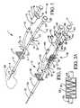
- FIG. 1is a perspective view of an illustrative embodiment of the device of the present invention, with a cannula of the device inserted in a patient (in phantom);
- FIG. 2is a perspective view of another illustrative embodiment of the device of the present invention.
- FIG. 2Ais a side view of a folded tubing volumeter of the device of the present invention.
- FIG. 3is a cross-sectional view taken along section lines 3 - 3 in FIG. 2 ;
- FIG. 4is an exploded, perspective view of still another illustrative embodiment of the device of the present invention.
- FIG. 5is a side view of a port element of the device of FIG. 4 and a cap device removably engaging the port;
- FIG. 6is an exploded, perspective view of still another illustrative embodiment of the device of the present invention.
- FIG. 6Ais a side view of a port element of the device of FIG. 6 and a blood receptacle removably engaging the port;
- FIG. 6Bis a cross-section of a blood receptacle contained in a receptacle casing in another embodiment of the device of the present invention.
- the device 1includes a main tubing segment 2 which is typically a flexible material.
- a hub 4 of a cannula 3is threadibly or otherwise attached to the main tubing segment 2 .
- a tubing bifurcation 5is provided in the end of the main tubing segment 2 which is opposite or distal to the cannula 3 , and the tubing bifurcation S may be continuous with or a separate element with respect to the main tubing segment 2 .
- a tubing clamp 6is provided on the main tubing segment 2 between the cannula hub 4 and the tubing bifurcation 5 .
- the tubing clamp 6may be any type of clamp which is capable of facilitating selective and reversible blocking of the flow of fluids through the main tubing segment 2 .
- the tubing clamp 6is preferably capable of one-handed operation.
- a syringe tubing segment 9extends from a syringe tubing leg 5 a of the tubing bifurcation 5 and may be continuous with or a separate element with respect to the tubing bifurcation 5 .
- a syringe port 10is provided in the end of the syringe tubing 9 which is opposite the tubing bifurcation 5 .
- the syringe port 10may a needle-less syringe port such as a female luer-lock connector element or other type of threaded element known by those skilled in the art, or may be any type of threadless connector which is capable of providing reversible and secure fluid communication between a syringe 13 and the syringe tubing segment 9 .
- the syringe 13may be conventional and typically includes a cylindrical syringe barrel 14 having a syringe connector 15 such as a male luer-lock connector element, for example, or other structure which is capable of removably and securely engaging the companion syringe port 10 .
- the syringe 13typically further includes barrel flanges 16 and an extendible and retractable syringe plunger 17 .
- a collector tubing segment 19extends from a collector tubing leg 5 b of the tubing bifurcation 5 and may be continuous with or a separate element with respect to the tubing bifurcation 5 .
- An indicator unit 18 of the device 1includes a volumeter tubing segment 20 which is provided in fluid communication with the collector tubing segment 19 .
- the indicator unit 18may be removably attached to the collector tubing segment 19 by a tubing connector 21 , which may include a receiver element 22 provided on the collector tubing 19 and an insertion element 23 provided on the volumeter tubing segment 20 , as shown.
- the insertion element 23defines a fluid-sealed end of the indicator unit 18 in which fluid is incapable of escaping from the interior to the exterior of the indicator unit 18 through the tubing connector 21 .
- the receiver element 22may be provided on the volumeter tubing segment 20 and the insertion element 23 may be provided on the collector tubing segment 19 .
- the receiver element 22may be a syringe port adapted for removably receiving a syringe for the administration of medical fluids to a patient, as hereinafter further described. It is understood that the indicator unit 18 may be fixedly rather than removably attached to the collector tubing segment 19 .
- a connector 7(in phantom) may be provided between the clamp 6 and the bifurcation 5 to facilitate disconnecting the syringe tubing segment 9 and syringe port 10 , together with the connected indicator unit 18 , from the main tubing segment 2 , in order to discard the syringe tubing segment 9 and indicator unit 18 , as desired.
- the indicator unit 18may further include a volumeter 26 , which is typically a volumeter chamber and made of a transparent material, provided in the volumeter tubing segment 20 .
- the volumeter 26may be an elongated segment of transparent coiled or folded tubing, as hereinafter described with respect to FIGS. 2 , 2 A and 4 .
- Membrane tubing 28 of the indicator unit 18extends from the volumeter 26 , and an air-permeable membrane 29 is provided on the membrane tubing 28 .
- the air-permeable membrane 29is preferably impermeable to liquids and may be any structure which is capable of facilitating bidirectional flow of air in the membrane tubing 28 toward the membrane 29 or bidirectional flow of air between the volumeter chamber 26 and the membrane tubing 28 while preventing the flow of blood out from the membrane tubing 28 .
- the device 1is initially used to remove blood from a subcutaneous vein of a patient 30 for blood sampling purposes. Accordingly, the clamp 6 is adjusted to the closed position to seal the main tubing segment 2 between the cannula 3 and the tubing bifurcation 5 .
- the tubing connector 21is inspected to ensure an airtight and fluid-tight connection between the collector tubing segment 19 and the volumeter tubing segment 20 of the indicator unit 18 .
- the cannula 3With the main tubing segment 2 , the syringe tubing segment 9 , the collector tubing segment 19 and the indicator unit 18 containing air, the cannula 3 is inserted into the vein of the patient 30 through the skin, as shown.
- the cannula 3is typically taped in place to immobilize the device 1 on the patient 30 .
- the clamp 6is adjusted to open the main tubing segment 2 . Accordingly, as blood flows from the vein of the patient 30 through the cannula 3 and the main tubing segment 2 , air is displaced by the advancing blood from the main tubing segment 2 , the collector tubing segment 19 and the indicator unit 18 , respectively, toward the membrane 29 .
- the bloodflows from the main tubing segment 2 and collector tubing leg 5 b of the tubing bifurcation 5 , into the collector tubing segment 19 and does not enter the syringe tubing segment 9 .
- Bloodcontinues to flow from the main tubing segment 2 and collector tubing segment 19 , through the tubing connector 21 and volumeter tubing segment 20 , respectively, of the indicator unit 18 and enters and collects in the volumeter chamber 26 .
- the syringe plunger 17is slowly extended from the syringe barrel 14 of the blood collecting syringe 13 to initially draw air from the syringe tubing segment 9 and into the syringe barrel 14 of the syringe 13 , thereby inducing a drop in air pressure inside the syringe tubing segment 9 relative to both the pressure in the collector tubing segment 19 and the intrinsic venous pressure in the main tubing segment 2 .
- This pressure dropcauses blood to flow from the volumeter chamber 26 , the volumeter tubing segment 20 and the collector tubing segment 19 , respectively, and enter the syringe tubing segment 9 and then the syringe barrel 14 of the syringe 13 .
- This extension of the plunger 17 from the syringe barrel 14 at a relatively slow, controlled rateensures that blood is extracted from the vein of the patient 30 and into the device 1 using the intrinsic flow pressure of the blood in the vein and prevents application of vacuum pressure to the vein which would tend to collapse the vein and hinder further flow of blood therefrom, as well as prevents or minimizes hemolysis of red blood cells in the extracted blood.
- the syringe plunger 17is pulled from the syringe barrel 14 at a rate which is sufficient to facilitate maintaining a substantially constant volume of blood in the volumeter chamber 26 as blood continues to be obtained from the main tubing segment 2 , through the syringe tubing segment 9 and into the blood collection syringe 13 .
- the volumeter 26may be omitted from the indicator unit 18 , in which case the indicator unit 18 may be a segment of clear tubing or any other element which is capable of enabling a user of the device 1 to visually inspect the progress of blood flow therethrough and prevent the air/fluid interface from passing beyond the bifurcation 5 to the syringe tubing segment 9 while obtaining the blood sample.
- the tubing clamp 6is adjusted to block further flow of blood through the main tubing segment 2 .
- the syringe plunger 17 of the syringe 13is extended from the syringe barrel 14 until all residual blood has been drawn from the indicator unit 18 , the collector tubing segment 19 and the syringe tubing segment 9 , and into the syringe barrel 14 .
- airis drawn through the indicator unit 18 through the membrane 29 , the collector tubing segment 19 and the syringe tubing segment 9 , respectively, until these elements are filled with air.
- the blood-filled syringe 13is then removed from the device 1 by disconnecting the syringe connector 15 from the syringe port 10 , and the blood collected in the syringe 13 is subjected to blood testing. Additional blood samples may be collected in an additional syringe or syringes, as needed, by attaching each additional empty syringe 13 to the syringe tubing segment 9 at the syringe port 10 and collecting the additional samples of blood in the syringe 13 or successive syringes 13 , in the manner heretofore described.
- the device 1may be used to administer medical fluids to the patient 30 , as follows.
- a syringe 13the barrel 14 of which contains a supply of saline flush solution, is initially attached to the syringe port 10 .
- the syringe plunger 17is subsequently depressed into the fluid-filled syringe barrel 14 , the saline solution is ejected therefrom and flows through the syringe tubing segment 9 , the collector tubing segment 19 , the volumeter tubing segment 20 and into the volumeter chamber 26 , respectively.
- the volumeter tubing segment 20may then be disconnected from the collector tubing segment 19 at the tubing connector 21 and discarded along with the volumeter chamber 26 , the membrane tubing 28 and the membrane 29 of the indicator unit 18 , as desired.
- the tubing clamp 6is then again adjusted to the open position and depression of the syringe plunger 17 into the syringe barrel 14 is continued to flush the main tubing segment 2 with saline flush solution.
- the syringe 13is then removed and a replacement syringe 13 containing a fluid medication or a catheter (not shown) connected to an IV bag (not shown) may then be attached to the syringe port 10 for the administration of medical fluids to the patient 30 through the syringe tubing segment 9 , or alternatively, through the syringe port 22 , the collector tubing segment 19 and the main tubing segment 2 , respectively.
- the tubing clamp 6is adjusted to the closed position.
- a replacement indicator unit 18may then be attached to the collector tubing segment 19 at the tubing connector 21 .
- the plunger 17 of syringe 13emptied of the medical fluid contents, is then extended to draw residual medical fluids from the indicator unit 18 and syringe tubing segment 9 , and the syringe 13 is removed from the syringe port 10 and discarded.
- the clamp 6is now opened, allowing fluid from main tubing segment 2 to flow toward membrane 29 .
- Plunger 17is further extended recovering any saline/blood mix.
- the clamp 6is then closed, and another empty blood-collecting syringe 13 is connected to the syringe port 10 , the tubing clamp 6 is again adjusted to the open position, and the syringe 13 is used to obtain the additional blood from the patient 30 , respectively, as heretofore described.
- FIGS. 2 , 2 A and 3 of the drawingsanother illustrative embodiment of the device of the present invention is generally indicated by reference numeral 31 and includes a main tubing segment 32 , to one end of which is securely connected a hub 34 of a cannula 33 .
- a tubing bifurcation 35is provided in the opposite end of the main tubing segment 32 and defines a syringe tubing leg 35 a and an adjacent collector tubing leg 35 b .
- a tubing clamp 36 of selected designis provided on the main tubing segment 32 , between the cannula hub 34 and the tubing bifurcation 35 .
- the tubing clamp 36is capable of one-handed operation.
- a syringe tubing segment 39extends from the syringe tubing leg 35 a of the tubing bifurcation 35 .
- a syringe port 40which is typically a needle-less luer-lock connector, for example, is provided in the end of the syringe tubing 39 which is distal to the tubing bifurcation 35 .
- a syringe 43typically including a cylindrical syringe barrel 44 having a syringe connector 45 such as a male luer-lock connector element, for example, removably engages the syringe port 40 in fluid-tight connection therewith.
- the blood collection syringe 43may be conventional and typically further includes barrel flanges 46 and an extendible and retractable syringe plunger 47 .
- a collector tubing segment 49extends from the collector tubing leg 35 b of the tubing bifurcation 35 .
- a indicator unit 48may be removably connected to the collector tubing segment 49 at a tubing connector 51 , and a protective container such as a covering syringe 63 may be removably connected to the indicator unit 48 for purposes which will be hereinafter described.
- the indicator unit 48may include a volumeter 56 which is typically provided between a port tubing segment 59 and a volumeter tubing segment 50 and may be encased in a transparent volumeter casing 57 .
- the tubing connector 51may include a receiver element 52 which is typically provided on the collector tubing segment 49 and removably receives an insertion element 53 typically provided on the volumeter tubing segment 50 .
- the receiver element 52may be provided on the volumeter tubing segment 50 and the insertion element 53 provided on the collector tubing segment 49 .
- the volumeter 56is typically a clear, transparent device having an elongated, generally spiral configuration, as shown in FIG. 2 .
- the volumeter 56may alternatively be a volumeter chamber such as the volumeter chamber 26 heretofore described with respect to FIG. 1 .
- the volumeter 61may be configured as a folded volumeter tubing that is folded into a zigzag pattern in a transparent volumeter casing 62 .
- a syringe port 60which may be a needle-less female luer-lock connector, for example, is provided on the port tubing segment 59 of the indicator unit 48 .
- a residual blood collection reservoir 69typically may be covered by a syringe barrel 64 of a protective container such as the covering syringe 63 having a syringe connector 65 which may be a male luer-lock connector element, for example, for removable connection to the companion syringe port 60 .
- the protective covering syringe 63may include a pair of barrel flanges 66 extending from the syringe barrel 64 and a syringe plunger 67 slidably disposed in the barrel interior 68 ( FIG. 3 ) of the syringe barrel 64 .
- one or more barrel openings 64 aextend through the wall of the syringe barrel 64 .
- the blood-collecting reservoir 69is provided in the barrel interior 68 of the syringe barrel 64 .
- the reservoir 69may be a very thin, easily deformable balloon-type structure, which is typically partially collapsed and is provided in fluid communication with the cannula 33 and volumeter 56 .
- the reservoir 69is formed typically of a thin plastic material or a rubber material or other easily deformable material that allows the interior volume of the reservoir 69 to be maintained a: ambient air pressure.
- the reservoir 69includes an intake end 69 a which is typically secured in the syringe connector 65 and has an intake opening (not shown) which faces the syringe port 60 .
- the distal end of the reservoir 69is affixed to the plunger 67 , as shown in FIG. 3 .
- the reservoir 69is designed to receive residual blood from the volumeter 56 .
- the device 31is initially used to obtain blood from a subcutaneous vein of a patient (not shown) and may thereafter be used to administer medical fluids to the patient, as heretofore described with respect to the device 1 of FIG. 1 .
- the clamp 36is adjusted to the closed position to seal the main tubing segment 32 between the cannula 33 and the tubing bifurcation 35 ; the cannula 33 is inserted into the vein of the patient; the syringe connector 45 of the blood collection syringe 43 is attached to the syringe port 40 of the syringe tubing segment 39 ; and the clamp 36 is adjusted to open the main tubing segment 32 .
- Bloodcontinues to flow from the main tubing segment 32 and collector tubing segment 49 , through the tubing connector 51 and volumeter tubing segment 50 , respectively, and enters and collects in the volumeter 56 .
- this bloodis collected-in the blood collecting reservoir 69 ( FIG. 3 ) and may later be expelled from the covering syringe 63 as an additional blood sample, as hereinafter further described.
- the syringe plunger 47 of the blood collection syringe 43is slowly extended from the syringe barrel 44 of the blood collecting syringe 43 to initially draw air from the syringe tubing segment 39 and into the syringe barrel 44 of the syringe 43 , thereby inducing a drop in air pressure inside the syringe tubing segment 39 relative to the air pressure in the collector tubing segment 49 .
- Thiscauses blood to flow from the volumeter 56 , the volumeter tubing segment 50 and the collector tubing segment 49 , respectively, and enter the syringe tubing segment 39 and the syringe barrel 44 of the syringe 43 .
- the syringe plunger 47is pulled from the syringe barrel 44 at a rate which is sufficient to facilitate maintaining a substantially constant volume of blood in the volumeter 56 as blood continues to be obtained from the main tubing segment 32 , through the collector tubing segment 49 and volumeter tubing segment 50 , respectively, and into the volumeter 56 .
- This extension of the plunger 47 from the syringe barrel 44 at a relatively slow, controlled rateensures that blood is extracted from the vein of the patient and into the device 31 using the intrinsic flow pressure of the blood in the vein.
- the tubing clamp 36is adjusted to block further flow of blood through the main tubing segment 32 . While the tubing clamp 36 remains in the closed position, the syringe plunger 47 of the blood collection syringe 43 is extended from the syringe barrel 44 until all residual blood has been drawn from the volumeter 56 , the volumeter tubing segment 50 , the collector tubing segment 49 and the syringe tubing segment 39 , and into the syringe barrel 44 .
- the blood-filled blood collection syringe 43is then removed from the device 31 by disconnecting the syringe connector 45 from the syringe port 40 , and the blood collected therein is subjected to blood testing. Additional blood samples may be collected in an additional blood collection syringe or syringes, as needed, by attaching each additional empty blood collection syringe 43 to the syringe tubing segment 39 at the syringe port 40 and collecting the additional samples of blood in the blood collection syringe 43 or successive blood collection syringes 43 , as heretofore described. Any blood collected in the blood collection reservoir 69 ( FIG. 3 ) may be collected in the barrel 44 of the blood collection syringe 43 by pulling the plunger 47 from the syringe barrel 44 .
- the device 31may be used to administer medical fluids to the patient, as heretofore described with respect to the device 1 of FIG. 1 and as follows. After removal of the blood-filled blood collecting syringe 43 from the syringe port 40 , a replacement syringe 43 , the barrel 44 of which contains a supply of sterile normal saline flush solution, is securely attached to the syringe port 40 .
- the syringe plunger 47is then depressed into the syringe barrel 44 to force the saline solution through the syringe tubing segment 39 ; the collector tubing segment 49 ; the volumeter tubing segment 50 , the volumeter 56 and the port tubing segment 59 of the indicator unit 48 ; and into the blood collection reservoir 69 ( FIG. 3 ), respectively.
- the indicator unit 48may then be disconnected from the collector tubing segment 49 at the tubing connector 51 and discarded along with the residual blood collection reservoir 69 encased in the covering syringe 63 .
- any blood/saline mix remaining in the reservoir 69may be used for blood culture by allowing partial vacuum test tube or bottle to pull specimen into appropriate container.
- the tubing clamp 36is then again adjusted to the open position and depression of the syringe plunger 47 into the syringe barrel 44 is continued to flush the main tubing segment 32 with saline flush solution.
- the syringe 43is then removed and a replacement syringe 43 containing a fluid medication or a catheter (not shown) connected to an IV bag (not shown) may then be attached to the syringe port 40 for the administration of medical fluids to the patient through the syringe tubing segment 39 and the main tubing segment 32 , respectively.
- Additional blood samplesmay be obtained from the patient by removing the medical fluid-filled syringe 43 from the syringe port 40 , connecting a replacement indicator unit 48 and residual blood collection reservoir 69 to the collector tubing segment 49 , and connecting an empty blood-collecting syringe 43 to the syringe port 40 to obtain the blood from the patient, in the manner heretofore described.
- FIG. 4 of the drawingsstill another illustrative embodiment of the device of the present invention is generally indicated by reference numeral 71 and includes a main tubing segment 72 to which a hub 74 of a cannula 73 is threadibly or otherwise attached.
- a tubing bifurcation 75is provided in the end of the main tubing segment 72
- a tubing clamp 76is provided on the main tubing segment 72 .
- the tubing clamp 76is preferably capable of one-handed operation.
- a syringe tubing segment 79extends from a syringe tubing leg 75 a of the tubing bifurcation 75 , and a syringe port 80 is provided in the end of the syringe tubing 79 .
- a syringe 83which may be conventional typically includes a cylindrical syringe barrel 84 having a syringe connector 85 such as a male luer-lock connector element, for example, or other structure which removably engages the syringe port 80 .
- the syringe 83typically further includes barrel flanges 86 and an extendible and retractable syringe plunger 87 .
- a collector tubing segment 89extends from a collector tubing leg 75 b of the tubing bifurcation 75 .
- a syringe port 91which may be a female luer-lock connector element, for example, is provided on the collector tubing segment 89 .
- An indicator unit 88includes a volumeter tubing segment 90 having a connector element (not shown) such as a male luer-lock connector which is removably connected to the syringe port 91 .
- the indicator unit 88typically further includes a blood volumeter 96 which may be a transparent coiled or folded tubing as shown and heretofore described with respect to the volumeter 56 of the device 31 of FIG. 2 .
- the blood volumeter 96may be a volumeter chamber such as the volumeter chamber 26 heretofore described with respect to FIG. 1 .
- a membrane tubing segment 98 of the indicator unit 88extends from the volumeter 96 , and an self-sealing or other port 99 having a port receptacle 99 a is provided on the tubing segment 98 .
- a cap device 100preferably comprised of a distal air permeable membrane 102 and a proximal needle-less blunt probe or a protected needle 101 , is capable of being attached securely to the port 99 . It will be appreciated from a consideration of FIG.
- the air-permeable membrane 102is preferably impermeable to liquids and may be any structure which is capable of facilitating flow of air from the volumeter 96 and the membrane tubing 98 while preventing the flow of blood from the membrane tubing 98 .
- the exterior surface of the cap device 100may be provided with cap threads (not shown) which engage interior cap threads (not shown) of the port 99 to secure the membrane cap device 100 on the port 99 .
- the cap device 100may be securely attached to the port 99 using any other suitable technique known by those skilled in the art.
- the device 71may be used to obtain blood samples from a patient into one or multiple blood collection syringes 83 successively connected to the syringe port 80 . After all blood samples have been obtained at the port 80 , the tubing is then flushed with sterile normal saline solution in the same manner as heretofore described with respect to the syringe 13 of the device 1 of FIG. 1 and the syringe 43 of the device 31 of FIG. 2 . Medical fluids may then be introduced into the patient using a fluid-filled syringe or successive fluid-filled syringes 83 in the same manner as heretofore described with respect to the device 1 of FIG. 1 and the device 31 of FIG. 2 .
- the indicator unit 88 of the device 71may be removed from the syringe port 91 of the device 71 and a syringe (not shown) or IV catheter (not shown) may be connected to the syringe port 91 for the introduction of medical fluids into the patient along with the medical fluids introduced into the device 71 through the syringe tubing segment 79 using the syringe 83 or successive syringes 83 filled with medical fluid.
- FIGS. 6-6Banother illustrative embodiment of the device of the present invention is generally indicated by reference numeral 111 and includes a main tubing segment 112 to which is attached a hub 114 of a cannula 113 .
- a collector tubing segment 129extends from the main tubing segment 112 .
- a tubing clamp 116which is preferably capable of one-handed operation, is provided in the main tubing segment 112 .
- a collection unit 128includes a volumeter tubing segment 140 which is provided in fluid communication with the collector tubing segment 129 .
- the collection unit 128may be removably attached to the collector tubing segment 129 by a tubing connector 131 of selected design.
- the collection unit 128typically further includes a volumeter 136 that may be contained inside a volumeter casing 137 .
- a port tubing segment 139extends from the volumeter 136 , and a port 141 is provided on the distal end of the port tubing segment 139 .
- the port 141may be a needle-less port or a protective needle port, for example, known by those skilled in the art.
- a port opening 143extends into the port 141 for removably receiving a companion receptacle connector 149 that extends from an inlet end of a collapsible and expandable blood receptacle 146 .
- the blood receptacle 146may be made of thin plastic, rubber or other deformable material and has a volume of typically from about 1 ⁇ 2 cc to about 10 cc, depending on laboratory requirements and the type of blood test to be conducted. As further shown in FIG. 6A , the blood receptacle 146 may be attached to an attachment sleeve 147 into which the receptacle connector 149 extends. As shown in FIG. 6 , the port 141 may be provided with exterior port threads 142 that engage interior sleeve threads 148 provided in the attachment sleeve 147 to removably attach the blood receptacle 146 in fluid communication with the port 141 .
- the attachment sleeve 147may be attached to the port 141 using any of a variety of alternative techniques known by those skilled in the art.
- the blood receptacle 146may be provided inside a receptacle casing 150 having one or more casing openings 151 .
- the distal end of the blood receptacle 146is attached or tethered to the receptacle casing 150 using an enclosure anchor 152 .
- a tubing bifurcation 115may be provided in the distal end of the main tubing segment 112 , in which case a syringe tubing segment 119 extends from a syringe tubing leg 115 a of the tubing bifurcation 115 and the collector tubing segment 129 extends from a collector tubing leg 115 b of the tubing bifurcation 115 .
- a syringe port 120is provided in the distal end of the syringe tubing 119 and removably receives a syringe 123 to obtain blood samples from and/or administer medical fluids to a patient, as hereinafter described.
- the blood receptacle 146is be used to collect blood samples from a patient for subsequent testing of the blood samples and then removed from the port 141 for testing of the blood samples.
- a syringe (not shown) or cathetercan then be attached to the port 141 for the administration of medical fluids to the patient, as hereinafter further described.
- the cannula 113is inserted into a subcutaneous vein (not shown) of a patient and the device 111 is taped in place. Because venous blood pressure inside the accessed vein is higher than ambient air pressure applied to the exterior of the blood receptacle 146 , blood flows from the vein though the main tubing segment 112 , the collector tubing segment 129 and the volumeter 136 , respectively, and enters the blood receptacle 146 .
- the attachment sleeve 147is removed from the port 141 and additional empty blood receptacles 146 can be successively attached to the port 141 to obtain additional blood samples, as needed, which blood receptacles 146 may be sized according to the blood tests desired.
- last blood receptacle 146is removed from the port 141 and discarded, thereby exposing the self-sealing port 141 .
- Normal salineis then used to flush the device 111 typically through the port 141 , and an IV line (not shown) may be connected to the port 141 , after which the device 111 is used as ordinary extension tubing.
- the device 111can be flushed with sterile normal saline and the medical fluids can be administered to the patient using a syringe 123 or IV line connected to the syringe port 120 , as heretofore described with respect to the embodiments of FIGS. 1-4 .
- the syringe 123is not needed to obtain the blood samples.
- bloodtypically flows slowly into the blood receptacle 146 , and thus, the syringe 123 can be used instead to obtain the blood samples through the syringe port 120 .
- a replacement syringe 123 or IV line(not shown) can then be attached to the port 120 for the administration of medical fluids to the patient through the syringe tubing segment 119 .
- the syringe tubing segment 119 , bifurcation 115 , and syringe port 120are optional components and can optionally be omitted from the device 111 , as desired, since the port 141 is suitable for both obtaining blood samples from and administering medical fluids to the patient.
- the volumeter 136is an optional element designed to assist the user in estimating the quantity of blood flowing from the main tubing segment 112 and into the receptacle 146 , in use of the device 111 .
Landscapes
- Health & Medical Sciences (AREA)
- Life Sciences & Earth Sciences (AREA)
- Engineering & Computer Science (AREA)
- Heart & Thoracic Surgery (AREA)
- Animal Behavior & Ethology (AREA)
- Veterinary Medicine (AREA)
- Hematology (AREA)
- Public Health (AREA)
- General Health & Medical Sciences (AREA)
- Biomedical Technology (AREA)
- Biophysics (AREA)
- Molecular Biology (AREA)
- Surgery (AREA)
- Medical Informatics (AREA)
- Pathology (AREA)
- Physics & Mathematics (AREA)
- Vascular Medicine (AREA)
- Manufacturing & Machinery (AREA)
- Anesthesiology (AREA)
- External Artificial Organs (AREA)
- Measurement Of The Respiration, Hearing Ability, Form, And Blood Characteristics Of Living Organisms (AREA)
- Infusion, Injection, And Reservoir Apparatuses (AREA)
Abstract
Description
Claims (19)
Priority Applications (9)
| Application Number | Priority Date | Filing Date | Title |
|---|---|---|---|
| US10/630,402US7662110B2 (en) | 2003-07-30 | 2003-07-30 | Devices for collecting blood and administering medical fluids |
| KR1020067002124AKR20060057588A (en) | 2003-07-30 | 2004-07-22 | Blood collection and medical fluid administration device |
| JP2006521941AJP2007500540A (en) | 2003-07-30 | 2004-07-22 | Blood collection and medical fluid administration device |
| AU2004261162AAU2004261162A1 (en) | 2003-07-30 | 2004-07-22 | Devices for collecting blood and administering medical fluid |
| PCT/US2004/023770WO2005011773A2 (en) | 2003-07-30 | 2004-07-22 | Devices for collecting blood and administering medical fluid |
| CA002576146ACA2576146A1 (en) | 2003-07-30 | 2004-07-22 | Devices for collecting blood and administering medical fluids |
| EP04757240AEP1648307A4 (en) | 2003-07-30 | 2004-07-22 | Devices for collecting blood and administering medical fluid |
| US11/059,994US7488297B2 (en) | 2003-07-30 | 2005-02-17 | Blood collecting devices |
| IL173310AIL173310A0 (en) | 2003-07-30 | 2006-01-23 | Devices for collecting blood and administering medical fluids |
Applications Claiming Priority (1)
| Application Number | Priority Date | Filing Date | Title |
|---|---|---|---|
| US10/630,402US7662110B2 (en) | 2003-07-30 | 2003-07-30 | Devices for collecting blood and administering medical fluids |
Related Child Applications (1)
| Application Number | Title | Priority Date | Filing Date |
|---|---|---|---|
| US11/059,994Continuation-In-PartUS7488297B2 (en) | 2003-07-30 | 2005-02-17 | Blood collecting devices |
Publications (2)
| Publication Number | Publication Date |
|---|---|
| US20050027233A1 US20050027233A1 (en) | 2005-02-03 |
| US7662110B2true US7662110B2 (en) | 2010-02-16 |
Family
ID=34103833
Family Applications (1)
| Application Number | Title | Priority Date | Filing Date |
|---|---|---|---|
| US10/630,402Expired - Fee RelatedUS7662110B2 (en) | 2003-07-30 | 2003-07-30 | Devices for collecting blood and administering medical fluids |
Country Status (8)
| Country | Link |
|---|---|
| US (1) | US7662110B2 (en) |
| EP (1) | EP1648307A4 (en) |
| JP (1) | JP2007500540A (en) |
| KR (1) | KR20060057588A (en) |
| AU (1) | AU2004261162A1 (en) |
| CA (1) | CA2576146A1 (en) |
| IL (1) | IL173310A0 (en) |
| WO (1) | WO2005011773A2 (en) |
Cited By (23)
| Publication number | Priority date | Publication date | Assignee | Title |
|---|---|---|---|---|
| US9744344B1 (en) | 2016-06-30 | 2017-08-29 | Velano Vascular, Inc. | Devices and methods for catheter placement within a vein |
| USD808013S1 (en) | 2016-10-27 | 2018-01-16 | Smiths Medical Asd, Inc. | Catheter |
| US10028691B2 (en) | 2015-01-30 | 2018-07-24 | Smiths Medical Asd, Inc. | Needle assembly with diagnostic analysis provisions |
| US20180220999A1 (en)* | 2017-02-07 | 2018-08-09 | New York University | Endoswab for Sampling and Culture in Minimally Invasive Surgery |
| US10099009B1 (en)* | 2015-03-12 | 2018-10-16 | Judith L. Anderson | Central venous catheter with reverse flush port |
| US10300247B2 (en) | 2016-02-03 | 2019-05-28 | Velano Vascular, Inc. | Devices and methods for fluid transfer through a placed peripheral intravenous catheter |
| US10433928B2 (en) | 2015-03-10 | 2019-10-08 | Allergan Pharmaceuticals Holdings (Ireland) Unlimited Company | Multiple needle injector |
| USD865948S1 (en) | 2017-03-24 | 2019-11-05 | Allergan, Inc. | Syringe device |
| US10596321B2 (en) | 2016-04-08 | 2020-03-24 | Allergan, Inc. | Aspiration and injection device |
| US10675440B2 (en) | 2016-02-18 | 2020-06-09 | Smiths Medical Asd, Inc. | Closed system catheter |
| US10674950B2 (en) | 2011-04-26 | 2020-06-09 | Velano Vascular, Inc. | Systems and methods for phlebotomy through a peripheral IV catheter |
| US10773056B2 (en) | 2017-03-21 | 2020-09-15 | Velano Vascular, Inc. | Systems and methods for controlling catheter device size |
| US10792427B2 (en) | 2014-05-13 | 2020-10-06 | Allergan, Inc. | High force injection devices |
| US10898118B2 (en) | 2015-01-30 | 2021-01-26 | Smiths Medical Asd, Inc. | Needle assembly with diagnostic analysis provisions |
| US11090461B2 (en) | 2017-03-21 | 2021-08-17 | Velano Vascular, Inc. | Devices and methods for fluid transfer through a placed peripheral intravenous catheter |
| US11185641B2 (en) | 2014-10-01 | 2021-11-30 | Allergan, Inc. | Devices for injection and dosing |
| US11207498B2 (en) | 2019-08-20 | 2021-12-28 | Velano Vascular, Inc. | Fluid transfer devices with extended length catheters and methods of using the same |
| US11331023B2 (en) | 2011-04-26 | 2022-05-17 | Velano Vascular, Inc. | Systems and methods for phlebotomy through a peripheral IV catheter |
| US11389624B2 (en) | 2020-11-26 | 2022-07-19 | Avia Vascular, Llc | Blood collection devices, systems, and methods |
| US11684719B2 (en) | 2013-05-23 | 2023-06-27 | Allergan, Inc. | Methods of treatment using a syringe extrusion accessory |
| WO2023192023A1 (en)* | 2022-04-01 | 2023-10-05 | Carefusion 303, Inc. | Hemolysis-reduction connector for direct blood draw |
| US11992668B2 (en) | 2008-12-02 | 2024-05-28 | Allergan, Inc. | Injection device |
| US12048541B2 (en) | 2018-06-08 | 2024-07-30 | Smiths Medical Asd, Inc. | Blood sequestration device and method |
Families Citing this family (19)
| Publication number | Priority date | Publication date | Assignee | Title |
|---|---|---|---|---|
| US20090259089A1 (en)* | 2008-04-10 | 2009-10-15 | Daniel Gelbart | Expandable catheter for delivery of fluids |
| US8905992B2 (en)* | 2011-11-07 | 2014-12-09 | General Electric Company | Portable microbubble and drug mixing device |
| US9295454B2 (en)* | 2012-09-21 | 2016-03-29 | Ko-Pen Wang | Double lumen or double wire endobronchial ultrasound-guided histology needle (EBUS) |
| US9962117B2 (en) | 2012-10-31 | 2018-05-08 | Vacutest Kima S.R.L. | Needle support assembly for a venous blood collection device with evacuated vial |
| US20240226430A1 (en)* | 2012-12-31 | 2024-07-11 | Medtg, Llc | Simultaneous infusion and blood collection devices |
| DK2938369T3 (en) | 2012-12-31 | 2018-08-06 | Medtg Llc | INFUSION AND BLOOD COLLECTION DEVICE |
| WO2014179525A1 (en)* | 2013-05-01 | 2014-11-06 | Bayer Medical Care Inc. | Attachment device for medical fluid container |
| CN104274254B (en)* | 2013-07-08 | 2016-06-01 | 中国医学科学院北京协和医院 | Animal venipuncture administration accurate quantification device |
| US11445954B2 (en)* | 2014-07-02 | 2022-09-20 | Site Saver, Inc. | Venous access device |
| WO2016105363A1 (en)* | 2014-12-23 | 2016-06-30 | Hewlett Packard Enterprise Development Lp | Detection of allergen exposure |
| EP3111976A1 (en)* | 2015-07-02 | 2017-01-04 | Cliniclab S.L. | Device for ejecting a hypodermic needle from a needle holder or syringe and corresponding blood sampling device |
| JP6999108B2 (en)* | 2016-08-23 | 2022-01-18 | 国立大学法人島根大学 | Blood collection device and blood collection kit |
| CN106943148A (en)* | 2017-02-28 | 2017-07-14 | 靖西市秀美边城农业科技有限公司 | Arterial blood air tube |
| CN106974662A (en)* | 2017-02-28 | 2017-07-25 | 靖西市秀美边城农业科技有限公司 | Artery blood sampling equipment |
| US11439333B2 (en)* | 2019-01-18 | 2022-09-13 | Becton, Dickinson And Company | Blood collection system including a baffle |
| EP4064989A4 (en)* | 2019-11-26 | 2023-12-06 | Medtg LLC | Infusion and blood collection devices and methods |
| US20210228127A1 (en)* | 2020-01-24 | 2021-07-29 | Becton, Dickinson And Company | Blood collection adapter and related devices to reduce hemolysis |
| TWI801822B (en)* | 2021-03-12 | 2023-05-11 | 研能科技股份有限公司 | Blood picker |
| US20230293814A1 (en)* | 2022-03-21 | 2023-09-21 | Becton, Dickinson And Company | Dressing-Integrated Tubing Occlusion |
Citations (32)
| Publication number | Priority date | Publication date | Assignee | Title |
|---|---|---|---|---|
| US2955595A (en)* | 1959-05-19 | 1960-10-11 | Fenwal Lab Inc | Therapeutic fluid sampling means |
| US3782382A (en) | 1972-02-03 | 1974-01-01 | K N Enterprises Inc | Means for blood administration and the like |
| US4186752A (en)* | 1978-08-30 | 1980-02-05 | Guerra Luis A | Device for taking blood and for injecting medication |
| US4187860A (en)* | 1977-09-01 | 1980-02-12 | The Kendall Company | Arterial blood collection device |
| US4257416A (en)* | 1979-05-03 | 1981-03-24 | David Prager | Multi-channel venipuncture infusion set |
| US4447235A (en)* | 1981-05-07 | 1984-05-08 | John M. Clarke | Thoracentesis device |
| USRE31873E (en) | 1976-09-08 | 1985-04-30 | Venous catheter device | |
| US4658655A (en)* | 1983-07-26 | 1987-04-21 | Terumo Kabushiki Kaisha | Fluid sampling device for medical use |
| US4701160A (en)* | 1986-06-11 | 1987-10-20 | Minnesota Mining And Manufacturing Company | Catheter and method for infusing fluid into a patient |
| US4981140A (en)* | 1986-09-12 | 1991-01-01 | Philip Wyatt | Method and apparatus for arterial and venous blood sampling |
| US5059168A (en)* | 1990-10-02 | 1991-10-22 | Stone Joseph J | Neonatal autotransfusion apparatus and method |
| US5069665A (en)* | 1990-07-02 | 1991-12-03 | Ng Raymond C | Fluid aspiration needle |
| US5084034A (en) | 1990-06-08 | 1992-01-28 | Tufts University | Method for sampling body fluids |
| US5089421A (en)* | 1989-02-06 | 1992-02-18 | Susan Dieffenbach | Method and apparatus for analyzing blood |
| US5203771A (en) | 1989-06-26 | 1993-04-20 | University Of Florida | Arterial/venous fluid transfer system |
| US5364377A (en) | 1990-01-18 | 1994-11-15 | Neil Alexander G B O | Fluid coupling and the method of manufacture |
| US5395347A (en)* | 1990-11-08 | 1995-03-07 | Mbo Laboratories, Inc. | Safe blood collection system |
| US5396899A (en)* | 1993-04-28 | 1995-03-14 | Duke University | Spinal puncture fluid collection apparatus |
| US5486159A (en) | 1993-10-01 | 1996-01-23 | Mahurkar; Sakharam D. | Multiple-lumen catheter |
| US5531672A (en)* | 1987-07-31 | 1996-07-02 | Lawrence A. Lynn | Blood aspiration assembly components and blunt needle aspirators |
| US5620008A (en)* | 1992-04-23 | 1997-04-15 | Migada Inc. | Fluid coupling device for a blood sampling unit |
| US5772608A (en)* | 1994-12-28 | 1998-06-30 | The Research Foundation Of State University Of New York | System for sampling arterial blood from a patient |
| US5772625A (en)* | 1996-11-19 | 1998-06-30 | Heyer-Schulte Neurocare, Inc. | External drainage shunt |
| US5795340A (en) | 1994-02-05 | 1998-08-18 | Lang; Volker | Microcatheter set |
| US5919146A (en)* | 1997-02-06 | 1999-07-06 | Tri-State Hospital Supply Corp. | Urine sampling and drainage device |
| US5961472A (en)* | 1997-09-26 | 1999-10-05 | Baxter International Inc. | Closed, one-handed blood sampling system |
| US6235010B1 (en)* | 1999-08-06 | 2001-05-22 | Becton Dickinson And Company | Closed system specimen collection container |
| US6413228B1 (en)* | 1998-12-28 | 2002-07-02 | Pro Duct Health, Inc. | Devices, methods and systems for collecting material from a breast duct |
| US6485428B1 (en)* | 1998-04-21 | 2002-11-26 | Dietmar Enk | Apparatus for and method of intravasal pressure measurement and low-contamination insertion of catheters for example into blood vessels |
| US6508778B1 (en) | 1998-06-01 | 2003-01-21 | Harvest Technologies Corporation | System for withdrawal of blood |
| US20040082899A1 (en)* | 1999-07-29 | 2004-04-29 | Jean-Marie Mathias | Biological fluid sampling apparatus |
| US20050096627A1 (en)* | 2003-11-03 | 2005-05-05 | Howard Mark E. | Fluid aspiration device |
Family Cites Families (4)
| Publication number | Priority date | Publication date | Assignee | Title |
|---|---|---|---|---|
| US4697622A (en)* | 1984-06-01 | 1987-10-06 | Parker Hannifin Corporation | Passive filling device |
| US4699613A (en)* | 1985-12-23 | 1987-10-13 | Donawick William J | Apparatus for the gravitational administration of fluids and drugs to large animals |
| US4838855A (en)* | 1987-07-31 | 1989-06-13 | Lynn Lawrence A | Blood aspiration assembly and method |
| JP3397051B2 (en)* | 1996-08-20 | 2003-04-14 | 松下電器産業株式会社 | Apparatus and method for mounting conductive ball |
- 2003
- 2003-07-30USUS10/630,402patent/US7662110B2/ennot_activeExpired - Fee Related
- 2004
- 2004-07-22WOPCT/US2004/023770patent/WO2005011773A2/enactiveApplication Filing
- 2004-07-22CACA002576146Apatent/CA2576146A1/ennot_activeAbandoned
- 2004-07-22JPJP2006521941Apatent/JP2007500540A/enactivePending
- 2004-07-22AUAU2004261162Apatent/AU2004261162A1/ennot_activeAbandoned
- 2004-07-22EPEP04757240Apatent/EP1648307A4/ennot_activeWithdrawn
- 2004-07-22KRKR1020067002124Apatent/KR20060057588A/ennot_activeCeased
- 2006
- 2006-01-23ILIL173310Apatent/IL173310A0/enunknown
Patent Citations (33)
| Publication number | Priority date | Publication date | Assignee | Title |
|---|---|---|---|---|
| US2955595A (en)* | 1959-05-19 | 1960-10-11 | Fenwal Lab Inc | Therapeutic fluid sampling means |
| US3782382A (en) | 1972-02-03 | 1974-01-01 | K N Enterprises Inc | Means for blood administration and the like |
| USRE31873F1 (en) | 1976-09-08 | 1988-11-15 | Venous catheter device | |
| USRE31873E (en) | 1976-09-08 | 1985-04-30 | Venous catheter device | |
| US4187860A (en)* | 1977-09-01 | 1980-02-12 | The Kendall Company | Arterial blood collection device |
| US4186752A (en)* | 1978-08-30 | 1980-02-05 | Guerra Luis A | Device for taking blood and for injecting medication |
| US4257416A (en)* | 1979-05-03 | 1981-03-24 | David Prager | Multi-channel venipuncture infusion set |
| US4447235A (en)* | 1981-05-07 | 1984-05-08 | John M. Clarke | Thoracentesis device |
| US4658655A (en)* | 1983-07-26 | 1987-04-21 | Terumo Kabushiki Kaisha | Fluid sampling device for medical use |
| US4701160A (en)* | 1986-06-11 | 1987-10-20 | Minnesota Mining And Manufacturing Company | Catheter and method for infusing fluid into a patient |
| US4981140A (en)* | 1986-09-12 | 1991-01-01 | Philip Wyatt | Method and apparatus for arterial and venous blood sampling |
| US5531672A (en)* | 1987-07-31 | 1996-07-02 | Lawrence A. Lynn | Blood aspiration assembly components and blunt needle aspirators |
| US5089421A (en)* | 1989-02-06 | 1992-02-18 | Susan Dieffenbach | Method and apparatus for analyzing blood |
| US5203771A (en) | 1989-06-26 | 1993-04-20 | University Of Florida | Arterial/venous fluid transfer system |
| US5364377A (en) | 1990-01-18 | 1994-11-15 | Neil Alexander G B O | Fluid coupling and the method of manufacture |
| US5084034A (en) | 1990-06-08 | 1992-01-28 | Tufts University | Method for sampling body fluids |
| US5069665A (en)* | 1990-07-02 | 1991-12-03 | Ng Raymond C | Fluid aspiration needle |
| US5059168A (en)* | 1990-10-02 | 1991-10-22 | Stone Joseph J | Neonatal autotransfusion apparatus and method |
| US5395347A (en)* | 1990-11-08 | 1995-03-07 | Mbo Laboratories, Inc. | Safe blood collection system |
| US5620008A (en)* | 1992-04-23 | 1997-04-15 | Migada Inc. | Fluid coupling device for a blood sampling unit |
| US5396899A (en)* | 1993-04-28 | 1995-03-14 | Duke University | Spinal puncture fluid collection apparatus |
| US5486159A (en) | 1993-10-01 | 1996-01-23 | Mahurkar; Sakharam D. | Multiple-lumen catheter |
| US5795340A (en) | 1994-02-05 | 1998-08-18 | Lang; Volker | Microcatheter set |
| US5772608A (en)* | 1994-12-28 | 1998-06-30 | The Research Foundation Of State University Of New York | System for sampling arterial blood from a patient |
| US5772625A (en)* | 1996-11-19 | 1998-06-30 | Heyer-Schulte Neurocare, Inc. | External drainage shunt |
| US5919146A (en)* | 1997-02-06 | 1999-07-06 | Tri-State Hospital Supply Corp. | Urine sampling and drainage device |
| US5961472A (en)* | 1997-09-26 | 1999-10-05 | Baxter International Inc. | Closed, one-handed blood sampling system |
| US6485428B1 (en)* | 1998-04-21 | 2002-11-26 | Dietmar Enk | Apparatus for and method of intravasal pressure measurement and low-contamination insertion of catheters for example into blood vessels |
| US6508778B1 (en) | 1998-06-01 | 2003-01-21 | Harvest Technologies Corporation | System for withdrawal of blood |
| US6413228B1 (en)* | 1998-12-28 | 2002-07-02 | Pro Duct Health, Inc. | Devices, methods and systems for collecting material from a breast duct |
| US20040082899A1 (en)* | 1999-07-29 | 2004-04-29 | Jean-Marie Mathias | Biological fluid sampling apparatus |
| US6235010B1 (en)* | 1999-08-06 | 2001-05-22 | Becton Dickinson And Company | Closed system specimen collection container |
| US20050096627A1 (en)* | 2003-11-03 | 2005-05-05 | Howard Mark E. | Fluid aspiration device |
Cited By (46)
| Publication number | Priority date | Publication date | Assignee | Title |
|---|---|---|---|---|
| US11992668B2 (en) | 2008-12-02 | 2024-05-28 | Allergan, Inc. | Injection device |
| US10674950B2 (en) | 2011-04-26 | 2020-06-09 | Velano Vascular, Inc. | Systems and methods for phlebotomy through a peripheral IV catheter |
| US11331023B2 (en) | 2011-04-26 | 2022-05-17 | Velano Vascular, Inc. | Systems and methods for phlebotomy through a peripheral IV catheter |
| US10799167B1 (en) | 2011-04-26 | 2020-10-13 | Velano Vascular, Inc. | Systems and methods for phlebotomy through a peripheral IV catheter |
| US10729367B1 (en) | 2011-04-26 | 2020-08-04 | Velano Vascular, Inc. | Systems and methods for phlebotomy through a peripheral IV catheter |
| US11957466B2 (en) | 2011-04-26 | 2024-04-16 | Velano Vascular, Inc. | Systems and methods for phlebotomy through a peripheral IV catheter |
| US11684719B2 (en) | 2013-05-23 | 2023-06-27 | Allergan, Inc. | Methods of treatment using a syringe extrusion accessory |
| US10792427B2 (en) | 2014-05-13 | 2020-10-06 | Allergan, Inc. | High force injection devices |
| US11185641B2 (en) | 2014-10-01 | 2021-11-30 | Allergan, Inc. | Devices for injection and dosing |
| US10028691B2 (en) | 2015-01-30 | 2018-07-24 | Smiths Medical Asd, Inc. | Needle assembly with diagnostic analysis provisions |
| US10898118B2 (en) | 2015-01-30 | 2021-01-26 | Smiths Medical Asd, Inc. | Needle assembly with diagnostic analysis provisions |
| US10433928B2 (en) | 2015-03-10 | 2019-10-08 | Allergan Pharmaceuticals Holdings (Ireland) Unlimited Company | Multiple needle injector |
| US10099009B1 (en)* | 2015-03-12 | 2018-10-16 | Judith L. Anderson | Central venous catheter with reverse flush port |
| US11717649B2 (en) | 2016-02-03 | 2023-08-08 | Velano Vascular, Inc. | Devices and methods for fluid transfer through a placed peripheral intravenous catheter |
| US10300247B2 (en) | 2016-02-03 | 2019-05-28 | Velano Vascular, Inc. | Devices and methods for fluid transfer through a placed peripheral intravenous catheter |
| US12161821B2 (en) | 2016-02-03 | 2024-12-10 | Velano Vascular, Inc. | Devices and methods for fluid transfer through a placed peripheral intravenous catheter |
| US11400259B2 (en) | 2016-02-03 | 2022-08-02 | Velano Vascular, Inc. | Devices and methods for fluid transfer through a placed peripheral intravenous catheter |
| US12343482B2 (en) | 2016-02-18 | 2025-07-01 | Icu Medical, Inc. | Closed system catheter |
| US10675440B2 (en) | 2016-02-18 | 2020-06-09 | Smiths Medical Asd, Inc. | Closed system catheter |
| US10596321B2 (en) | 2016-04-08 | 2020-03-24 | Allergan, Inc. | Aspiration and injection device |
| US11890457B2 (en) | 2016-04-08 | 2024-02-06 | Allergan, Inc. | Aspiration and injection device |
| US9744344B1 (en) | 2016-06-30 | 2017-08-29 | Velano Vascular, Inc. | Devices and methods for catheter placement within a vein |
| USD893711S1 (en) | 2016-10-27 | 2020-08-18 | Smiths Medical Asd, Inc. | Catheter assembly |
| USD808013S1 (en) | 2016-10-27 | 2018-01-16 | Smiths Medical Asd, Inc. | Catheter |
| US10912539B2 (en)* | 2017-02-07 | 2021-02-09 | New York University | Endoswab for sampling and culture in minimally invasive surgery |
| US20180220999A1 (en)* | 2017-02-07 | 2018-08-09 | New York University | Endoswab for Sampling and Culture in Minimally Invasive Surgery |
| US11090461B2 (en) | 2017-03-21 | 2021-08-17 | Velano Vascular, Inc. | Devices and methods for fluid transfer through a placed peripheral intravenous catheter |
| US10773056B2 (en) | 2017-03-21 | 2020-09-15 | Velano Vascular, Inc. | Systems and methods for controlling catheter device size |
| US11351340B2 (en) | 2017-03-21 | 2022-06-07 | Velano Vascular, Inc. | Systems and methods for controlling catheter device size |
| US12017016B2 (en) | 2017-03-21 | 2024-06-25 | Velano Vascular, Inc. | Devices and methods for fluid transfer through a placed peripheral intravenous catheter |
| US11583661B2 (en) | 2017-03-21 | 2023-02-21 | Velano Vascular, Inc. | Devices and methods for fluid transfer through a placed peripheral intravenous catheter |
| US12194250B2 (en) | 2017-03-21 | 2025-01-14 | Velano Vascular, Inc. | Systems and methods for controlling catheter device size |
| US11744990B2 (en) | 2017-03-21 | 2023-09-05 | Velano Vascular, Inc. | Systems and methods for controlling catheter device size |
| US12138402B2 (en) | 2017-03-21 | 2024-11-12 | Velano Vascular, Inc. | Devices and methods for fluid transfer through a placed peripheral intravenous catheter |
| USD865950S1 (en) | 2017-03-24 | 2019-11-05 | Allergan, Inc. | Syringe device |
| USD867582S1 (en) | 2017-03-24 | 2019-11-19 | Allergan, Inc. | Syringe device |
| USD866753S1 (en) | 2017-03-24 | 2019-11-12 | Allergan, Inc. | Syringe device |
| USD865949S1 (en) | 2017-03-24 | 2019-11-05 | Allergan, Inc. | Syringe device |
| USD865948S1 (en) | 2017-03-24 | 2019-11-05 | Allergan, Inc. | Syringe device |
| US12048541B2 (en) | 2018-06-08 | 2024-07-30 | Smiths Medical Asd, Inc. | Blood sequestration device and method |
| US11207498B2 (en) | 2019-08-20 | 2021-12-28 | Velano Vascular, Inc. | Fluid transfer devices with extended length catheters and methods of using the same |
| US11638806B2 (en) | 2020-11-26 | 2023-05-02 | Avia Vascular, Llc | Blood collection devices, systems, and methods |
| US11389624B2 (en) | 2020-11-26 | 2022-07-19 | Avia Vascular, Llc | Blood collection devices, systems, and methods |
| US11452847B1 (en) | 2020-11-26 | 2022-09-27 | Avia Vascular, Llc | Blood collection devices, systems, and methods |
| WO2023192023A1 (en)* | 2022-04-01 | 2023-10-05 | Carefusion 303, Inc. | Hemolysis-reduction connector for direct blood draw |
| EP4523624A3 (en)* | 2022-04-01 | 2025-04-16 | Carefusion 303 Inc. | Hemolysis-reduction connector for direct blood draw |
Also Published As
| Publication number | Publication date |
|---|---|
| AU2004261162A1 (en) | 2005-02-10 |
| WO2005011773A2 (en) | 2005-02-10 |
| EP1648307A2 (en) | 2006-04-26 |
| KR20060057588A (en) | 2006-05-26 |
| IL173310A0 (en) | 2006-06-11 |
| WO2005011773A3 (en) | 2006-02-16 |
| AU2004261162A2 (en) | 2005-02-10 |
| US20050027233A1 (en) | 2005-02-03 |
| EP1648307A4 (en) | 2009-08-05 |
| JP2007500540A (en) | 2007-01-18 |
| CA2576146A1 (en) | 2005-02-10 |
Similar Documents
| Publication | Publication Date | Title |
|---|---|---|
| US7662110B2 (en) | Devices for collecting blood and administering medical fluids | |
| US6740063B2 (en) | Luer receiving vascular access system | |
| JP2651425B2 (en) | Blood suction assembly | |
| US5947932A (en) | Closed system blood sampling device | |
| AU762878B2 (en) | Apparatus for obtaining liquid samples | |
| US7488297B2 (en) | Blood collecting devices | |
| US5611782A (en) | Method of delivering a blood sample to an evacuated receptacle | |
| US20080200837A1 (en) | Disposable, closed blood sampling system for use in medical conduit line | |
| JP6441916B2 (en) | Integrated closed IV line suction system | |
| US10980462B2 (en) | Micro-volume blood transfer device | |
| JP2001517522A (en) | Closed one-handed blood sample extraction system | |
| CN204181960U (en) | A kind of remaining needle | |
| US5456678A (en) | Safety device for taking samples and performing infusions | |
| CN210673340U (en) | A collection system for blood is gathered | |
| JP4007681B2 (en) | Winged blood collection needle | |
| CN116585593A (en) | Instrument propulsion device | |
| CN219720696U (en) | Blood collection assembly and blood detection and diagnosis platform | |
| CN213312397U (en) | Infusion apparatus for measuring central venous pressure | |
| CN219803721U (en) | Blood sampling device | |
| WO2002005707A1 (en) | Apparatus for obtaining liquid samples |
Legal Events
| Date | Code | Title | Description |
|---|---|---|---|
| AS | Assignment | Owner name:ONE STICK, LLC, LOUISIANA Free format text:ASSIGNMENT OF ASSIGNORS INTEREST;ASSIGNOR:FLAHERTY, PATRICE;REEL/FRAME:015198/0279 Effective date:20040405 Owner name:ONE STICK, LLC,LOUISIANA Free format text:ASSIGNMENT OF ASSIGNORS INTEREST;ASSIGNOR:FLAHERTY, PATRICE;REEL/FRAME:015198/0279 Effective date:20040405 | |
| STCF | Information on status: patent grant | Free format text:PATENTED CASE | |
| FEPP | Fee payment procedure | Free format text:PATENT HOLDER CLAIMS MICRO ENTITY STATUS, ENTITY STATUS SET TO MICRO (ORIGINAL EVENT CODE: STOM); ENTITY STATUS OF PATENT OWNER: MICROENTITY | |
| FPAY | Fee payment | Year of fee payment:4 | |
| FEPP | Fee payment procedure | Free format text:MAINTENANCE FEE REMINDER MAILED (ORIGINAL EVENT CODE: REM.) | |
| FEPP | Fee payment procedure | Free format text:SURCHARGE FOR LATE PAYMENT, MICRO ENTITY (ORIGINAL EVENT CODE: M3555) | |
| MAFP | Maintenance fee payment | Free format text:PAYMENT OF MAINTENANCE FEE, 8TH YEAR, MICRO ENTITY (ORIGINAL EVENT CODE: M3552) Year of fee payment:8 | |
| FEPP | Fee payment procedure | Free format text:MAINTENANCE FEE REMINDER MAILED (ORIGINAL EVENT CODE: REM.); ENTITY STATUS OF PATENT OWNER: MICROENTITY | |
| LAPS | Lapse for failure to pay maintenance fees | Free format text:PATENT EXPIRED FOR FAILURE TO PAY MAINTENANCE FEES (ORIGINAL EVENT CODE: EXP.); ENTITY STATUS OF PATENT OWNER: MICROENTITY | |
| STCH | Information on status: patent discontinuation | Free format text:PATENT EXPIRED DUE TO NONPAYMENT OF MAINTENANCE FEES UNDER 37 CFR 1.362 | |
| FP | Lapsed due to failure to pay maintenance fee | Effective date:20220216 |