US7662094B2 - Optical head assembly with dome, and device for use thereof - Google Patents
Optical head assembly with dome, and device for use thereofDownload PDFInfo
- Publication number
- US7662094B2 US7662094B2US10/437,436US43743603AUS7662094B2US 7662094 B2US7662094 B2US 7662094B2US 43743603 AUS43743603 AUS 43743603AUS 7662094 B2US7662094 B2US 7662094B2
- Authority
- US
- United States
- Prior art keywords
- dome
- optical
- imaging
- illumination
- optical head
- Prior art date
- Legal status (The legal status is an assumption and is not a legal conclusion. Google has not performed a legal analysis and makes no representation as to the accuracy of the status listed.)
- Expired - Fee Related
Links
- 230000003287optical effectEffects0.000titleclaimsabstractdescription113
- 238000003384imaging methodMethods0.000claimsabstractdescription37
- 238000005286illuminationMethods0.000claimsabstractdescription36
- 238000002955isolationMethods0.000claimsdescription26
- 230000000712assemblyEffects0.000claimsdescription4
- 238000000429assemblyMethods0.000claimsdescription4
- 239000002131composite materialSubstances0.000claimsdescription3
- 230000005855radiationEffects0.000claimsdescription2
- 238000000034methodMethods0.000abstractdescription9
- 239000002775capsuleSubstances0.000description12
- 239000000463materialSubstances0.000description11
- 238000001727in vivoMethods0.000description8
- 230000004888barrier functionEffects0.000description7
- 239000007787solidSubstances0.000description7
- 238000011503in vivo imagingMethods0.000description6
- 229920000089Cyclic olefin copolymerPolymers0.000description4
- 239000004033plasticSubstances0.000description4
- 229920003023plasticPolymers0.000description4
- 238000003466weldingMethods0.000description4
- 238000004026adhesive bondingMethods0.000description3
- UNCGJRRROFURDV-UHFFFAOYSA-N1,2-dichloro-3-(3,4-dichlorophenyl)benzeneChemical compoundC1=C(Cl)C(Cl)=CC=C1C1=CC=CC(Cl)=C1ClUNCGJRRROFURDV-UHFFFAOYSA-N0.000description2
- BZTYNSQSZHARAZ-UHFFFAOYSA-N2,4-dichloro-1-(4-chlorophenyl)benzeneChemical compoundC1=CC(Cl)=CC=C1C1=CC=C(Cl)C=C1ClBZTYNSQSZHARAZ-UHFFFAOYSA-N0.000description2
- 239000004713Cyclic olefin copolymerSubstances0.000description2
- XUIMIQQOPSSXEZ-UHFFFAOYSA-NSiliconChemical compound[Si]XUIMIQQOPSSXEZ-UHFFFAOYSA-N0.000description2
- 239000007788liquidSubstances0.000description2
- 229910052710siliconInorganic materials0.000description2
- 239000010703siliconSubstances0.000description2
- YFSLABAYQDPWPF-UHFFFAOYSA-N1,2,3-trichloro-4-(2,3,5-trichlorophenyl)benzeneChemical compoundClC1=CC(Cl)=C(Cl)C(C=2C(=C(Cl)C(Cl)=CC=2)Cl)=C1YFSLABAYQDPWPF-UHFFFAOYSA-N0.000description1
- TULCXSBAPHCWCF-UHFFFAOYSA-N1,2,4-trichloro-5-(4-chlorophenyl)benzeneChemical compoundC1=CC(Cl)=CC=C1C1=CC(Cl)=C(Cl)C=C1ClTULCXSBAPHCWCF-UHFFFAOYSA-N0.000description1
- WBTMFEPLVQOWFI-UHFFFAOYSA-N1,3-dichloro-5-(2,5-dichlorophenyl)benzeneChemical compoundClC1=CC=C(Cl)C(C=2C=C(Cl)C=C(Cl)C=2)=C1WBTMFEPLVQOWFI-UHFFFAOYSA-N0.000description1
- 241001101998GaliumSpecies0.000description1
- 239000004793PolystyreneSubstances0.000description1
- NIXOWILDQLNWCW-UHFFFAOYSA-Nacrylic acid groupChemical groupC(C=C)(=O)ONIXOWILDQLNWCW-UHFFFAOYSA-N0.000description1
- 230000002411adverseEffects0.000description1
- 230000000903blocking effectEffects0.000description1
- 229920001577copolymerPolymers0.000description1
- 238000010586diagramMethods0.000description1
- 230000009977dual effectEffects0.000description1
- 230000000694effectsEffects0.000description1
- 210000001035gastrointestinal tractAnatomy0.000description1
- 229910052738indiumInorganic materials0.000description1
- APFVFJFRJDLVQX-UHFFFAOYSA-Nindium atomChemical compound[In]APFVFJFRJDLVQX-UHFFFAOYSA-N0.000description1
- 238000012986modificationMethods0.000description1
- 230000004048modificationEffects0.000description1
- 229920003229poly(methyl methacrylate)Polymers0.000description1
- 239000004417polycarbonateSubstances0.000description1
- 150000003071polychlorinated biphenylsChemical class0.000description1
- 229920000642polymerPolymers0.000description1
- 239000004926polymethyl methacrylateSubstances0.000description1
- 229920002223polystyrenePolymers0.000description1
- 229920002635polyurethanePolymers0.000description1
- 239000004814polyurethaneSubstances0.000description1
- 239000000758substrateSubstances0.000description1
Images


Classifications
- A—HUMAN NECESSITIES
- A61—MEDICAL OR VETERINARY SCIENCE; HYGIENE
- A61B—DIAGNOSIS; SURGERY; IDENTIFICATION
- A61B1/00—Instruments for performing medical examinations of the interior of cavities or tubes of the body by visual or photographical inspection, e.g. endoscopes; Illuminating arrangements therefor
- A61B1/04—Instruments for performing medical examinations of the interior of cavities or tubes of the body by visual or photographical inspection, e.g. endoscopes; Illuminating arrangements therefor combined with photographic or television appliances
- A61B1/041—Capsule endoscopes for imaging
- A—HUMAN NECESSITIES
- A61—MEDICAL OR VETERINARY SCIENCE; HYGIENE
- A61B—DIAGNOSIS; SURGERY; IDENTIFICATION
- A61B1/00—Instruments for performing medical examinations of the interior of cavities or tubes of the body by visual or photographical inspection, e.g. endoscopes; Illuminating arrangements therefor
- A61B1/00064—Constructional details of the endoscope body
- A61B1/00071—Insertion part of the endoscope body
- A61B1/0008—Insertion part of the endoscope body characterised by distal tip features
- A61B1/00096—Optical elements
- A—HUMAN NECESSITIES
- A61—MEDICAL OR VETERINARY SCIENCE; HYGIENE
- A61B—DIAGNOSIS; SURGERY; IDENTIFICATION
- A61B1/00—Instruments for performing medical examinations of the interior of cavities or tubes of the body by visual or photographical inspection, e.g. endoscopes; Illuminating arrangements therefor
- A61B1/04—Instruments for performing medical examinations of the interior of cavities or tubes of the body by visual or photographical inspection, e.g. endoscopes; Illuminating arrangements therefor combined with photographic or television appliances
- A61B1/05—Instruments for performing medical examinations of the interior of cavities or tubes of the body by visual or photographical inspection, e.g. endoscopes; Illuminating arrangements therefor combined with photographic or television appliances characterised by the image sensor, e.g. camera, being in the distal end portion
- A61B1/051—Details of CCD assembly
- H—ELECTRICITY
- H04—ELECTRIC COMMUNICATION TECHNIQUE
- H04N—PICTORIAL COMMUNICATION, e.g. TELEVISION
- H04N23/00—Cameras or camera modules comprising electronic image sensors; Control thereof
- H04N23/50—Constructional details
- H04N23/555—Constructional details for picking-up images in sites, inaccessible due to their dimensions or hazardous conditions, e.g. endoscopes or borescopes
- H—ELECTRICITY
- H04—ELECTRIC COMMUNICATION TECHNIQUE
- H04N—PICTORIAL COMMUNICATION, e.g. TELEVISION
- H04N23/00—Cameras or camera modules comprising electronic image sensors; Control thereof
- H04N23/56—Cameras or camera modules comprising electronic image sensors; Control thereof provided with illuminating means
- A—HUMAN NECESSITIES
- A61—MEDICAL OR VETERINARY SCIENCE; HYGIENE
- A61B—DIAGNOSIS; SURGERY; IDENTIFICATION
- A61B1/00—Instruments for performing medical examinations of the interior of cavities or tubes of the body by visual or photographical inspection, e.g. endoscopes; Illuminating arrangements therefor
- A61B1/273—Instruments for performing medical examinations of the interior of cavities or tubes of the body by visual or photographical inspection, e.g. endoscopes; Illuminating arrangements therefor for the upper alimentary canal, e.g. oesophagoscopes, gastroscopes
Definitions
- the present inventionrelates generally to optical head assemblies, and more specifically to optical head assemblies for in vivo imaging devices.
- Devices and methods for performing in-vivo imaging of passages or cavities within a bodyare known in the art. Such devices may include, inter alia, various endoscopic imaging systems and devices for performing imaging in various internal body cavities. Generally, these devices perform in-vivo imaging using an imager such as an imaging sensor array (e.g., a CMOS camera, although other types of imagers may be used) and an internal light source, such as for example a “white LED” or any other suitable light source, which supplies the light for illuminating the area which needs to be imaged. Light is reflected from the surface illuminated by the light source and an optical system focuses the reflected light onto the CMOS imaging sensor.
- an imagersuch as an imaging sensor array (e.g., a CMOS camera, although other types of imagers may be used) and an internal light source, such as for example a “white LED” or any other suitable light source, which supplies the light for illuminating the area which needs to be imaged.
- an optical systemfocuses the reflected
- the optical systemmay include one or more optical elements, such as one or more lenses, one or more composite lens assemblies, one or more suitable optical filters, or any other suitable optical elements adapted for focusing an image on the imaging sensor and for manipulating light as is known in the art.
- the optical systemmay be attached to, or mounted on, or fabricated on or disposed adjacent to the imager light sensitive CMOS as is known in the art.
- the optical system and CMOS imaging sensorare typically accurately aligned to obtain proper focusing and optical use of the CMOS surface area. The small scale of parts makes it difficult to obtain proper alignment.
- optical headThe combination of the light source, imaging array (e.g. CMOS) and optical focusing system may be referred to as an optical head.
- the optical headis commonly placed behind an optical window or dome to, for example, isolate its electric components from liquids found in a body, which may interfere with the operation of these components.
- optical window or domeFor these optical systems it is advantageous to have the illuminating element and receiving means contained within a single compartment. Having a single optical window is advisable for hygienic and practical considerations as well.
- a system having the illumination element and means for receiving reflected light contained behind a single optical window or domemay have back-scatter and stray light produced by light remitted from the optical window itself received by the receiving means.
- a systemcontaining at least one illumination portion and at least one imaging portion behind a single dome with reduced adverse effects do to back-scatter and stray light and with improved alignment between image sensor and lens system.
- the domehas an optical system integrated therein.
- the domeis made of one or more materials and/or may be a multi sectional dome.
- the domemay be a combination of more than one material.
- the systemhas an alignment element integrated to the imaging portion and/or to the dome.
- the alignment elementmay be, for example, a shim, a cone, a shoulder, a lens holder, a ring or one or more positioning grooves, or other structures.
- the systemhas an optical isolation element integrated, typically in the imaging portion.
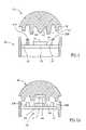
- FIG. 1illustrates an optical head assembly with a solid dome, according to an embodiment of the invention
- FIG. 2Aschematically illustrates a solid dome with an optical head assembly, according to another embodiment of the present invention
- FIG. 2Bschematically illustrates a shelled dome with an optical head assembly, according to one embodiment of the present invention
- FIG. 3schematically illustrates a shelled dome with an optical head assembly, according to another embodiment of the present invention
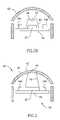
- FIG. 4Aschematically illustrates a cross sectional view of an optical head assembly with a multi-sectional dome according to an embodiment of the present invention
- FIG. 4Bschematically illustrates a cross sectional view of the imaging portion of an optical head assembly with multi-sectional dome according to an embodiment of the present invention
- FIG. 5schematically illustrates a cross sectional view of an optical head assembly with non-homogenous multi-sectional dome according to an embodiment of the present invention.
- FIG. 6schematically illustrates an in vivo imaging device with an optical head and dome, according to an embodiment of the invention.
- an optical head assembly with domemay be utilized for in vivo imaging.
- an optical head according to an embodiment of the inventioncan be incorporated in an in vivo device, such as a swallowable capsule for imaging the gastrointestinal (GI) tract, an endoscope, a catheter, a stent, a needle and others.
- an optical headis incorporated or attached onto the distal end (the end which is inserted into a patient's body) of an in vivo device.
- the optical headis incorporated into a swallowable imaging capsule, such as, for example, the capsule described in WO 01/65995 and/or in U.S. Pat. No. 5,604,531 to Iddan, which are assigned to the common assignee of the present invention and which are hereby incorporated by reference.
- some elementsmay be referred to as being “optical”, or as being adapted to generate, receive, translate, or the like, optical radiation, however it should be understood that some embodiments of the present invention may include equivalent elements that may be adapted to generate, receive, translate, or the like, other forms of energy (e.g., infra red energy), typically energies that may be suitable for imaging the body lumen, and that such non-optical elements may be combined with, or replace, the optical elements.
- other forms of energye.g., infra red energy
- Dome 10is a solid dome including an integrated optical system 14 and, optionally, alignment elements, for example, shoulders 16 and 18 for positioning dome 10 onto optical head 20 during assembly.
- Alignment elementsmay include opaque material.
- the alignment element(s)may be integral to the dome, (e.g., shoulders 16 and 18 ) optionally being made of the same material the as the dome.
- other alignment meanse.g. shims or other structures may be used or such means need not be used.
- optical system 14may include at least a lens.
- optical system 14may include one or more mirrors, prisms, composite lenses or any other suitable focusing and/or light directing elements. According to one embodiment the optical system 14 is positioned substantially near the inner surface 10 ′ of the dome 10 .
- Optical head 20includes for example, an imager such as an image sensor 22 , optical isolation element 30 , and one or more light sources 24 A and 24 B mounted on a supporting means, for example a printed circuit board (“PCB”) 28 . Other supporting means may be used. Further, other components or combinations of components may be used.
- Dome 10may be made from, for example, translucent or partially translucent material. Dome 10 may be made from, for example, PMMA, isoplastTM (poly urethane), Cyclic Olefin Polymer (COP), Cyclic Olefin Copolymer (COC), poly-carbonate, a copolymer of 70% polystyrene and 30% acrylic, having a refractive index at 588 nm of 1.564 (NAS) (other proportions and properties may be used) or any other suitable plastic, polymer, or material known in the art.
- the dome 10is typically used to, for example, isolate or protect electric or other components from liquids found in a body, and to protect the optical head 20 from an in-vivo or other external environment. Other or additional functionality may be attached to the dome 10 .
- Image sensor 22may include a single element or multiple elements, for example image sensor 22 may include an array of individual image sensors, and each of the independent image sensors may be adapted to operate cooperatively with each other image sensor. The individual image sensors may also be adapted to operate independently. Image sensor 22 may be a CMOS, a charge couple device (“CCD”), Indium Galium Arsenide (InGaAs), or any other suitable device.
- CCDcharge couple device
- InGaAsIndium Galium Arsenide
- Optical isolation element 30may be, for example, made from an opaque or translucent barrier, a light trap, an optical filter, a series of separate barriers, or any other suitable structure of any suitable material, such as for example opaque plastic.
- Optical isolation element 30may extend directly from the image sensor 22 or from PCB 28 .
- An optical filter(not shown) such as for example an IR reject filter may be placed in the device, for example, between the image sensor 22 and the optical system 14 .
- the illumination portionmay include suitable illumination sources such as color LEDs, laser diodes or white LEDs.
- the light sourcesmay have optical filters, such as IR reject filters, color filters, or other filters.
- One or more optical filtersmay be placed over one or more of the light sources. According to other embodiments a filter need not be included.
- solid dome 10 with one or more shoulders for example shoulders 16 and/or shoulder 18provide a guide for aligning the image sensor 22 with optical system 14 integrated onto solid dome 10 .
- One or more light sources, such as 24 A and/or 24 Bmay be positioned between shoulders 16 and 18 respectively for optimal lighting of a target object to be imaged (not shown).
- Light sources 24 A and 24 Bmay be mounted on PCB 28 with, for example, flexible connectors 32 so that light sources 24 A and 24 B can be properly positioned between one or more shoulders 16 and 18 during assembly of the dome 10 with optical head 20 .
- Other mounting methodsmay be used.
- one or more light sources 24 A and 24 Bare rigidly mounted on more than one PCB, for example, and alignment of image sensor 22 and light sources 24 A and 24 B between the shoulders 16 and 18 for example is accomplished by adjusting the relative position between the PCBs.
- One or more light sources 24 A and 24 Bradiate outward through the integrated dome toward an object (not shown) from which the light is reflected.
- Light rays reflected from a target objectare focused with optical system 14 on to image sensor 22 .
- Solid dome 10which essentially surrounds the light sources 24 A and 24 B with dome material, may avoid the backscatter occurring due to rays from the light source hitting an inner surface of a shelled dome by eliminating the common inner surface that exists in a shelled dome.
- Optical isolation element 30isolates image sensor 22 from stray light originating from light sources 24 A and 24 B.
- the inner and/or outer wall of shoulder 16may be covered with an opaque material (not shown) so as to, for example, provide an isolating well for image sensor 22 and integrated optical system 14 against stray and back scattered light originating from one or more light sources 24 A or 24 B.
- FIG. 2Aschematically illustrates a solid dome 66 with an optical head assembly 74 , according to one embodiment of the present invention.
- Optical head assembly 74includes for example, image sensor 22 , lens holder 66 with lens system 64 , and one or more light sources 24 A and 24 B mounted on a support means, for example PCB 72 .
- Image sensor 22may be a CMOS, a CCD or any functional equivalent.
- Lens holder 66fixes lens system 64 in a fixed position relative to the image sensor 22 so that, for example, optimal use of image sensor surface may be accomplished.
- Lens holder 66may be, for example, an extension from image sensor 22 or an extension from PCB 74 .
- lens holder 66may be separately added or may extend from another structure.
- lens holder 66 with integrated well 68may be, for example, made from an opaque or translucent barrier, a light trap, an optical filter, a series of separate barriers, or any other suitable structure of any suitable material such as for example opaque plastic.
- Lens holder 66may as such provide a dual purpose of aligning lens system 64 with image sensor 22 and blocking out stray light or back scatter originating from the light sources 24 A and 24 B.
- dome 66may be, for example, an ellipsoid shaped dome or any other shape having at least one focal curve, for example, as is described in WO 00/76391, which is assigned to the common assignee of the present invention and which is hereby incorporated by reference in its entirety.
- Other suitable shapes, such as shapes not shown in the figures,may of course be used.
- FIG. 2Bschematically illustrates an embodiment with a shelled dome 62 assembled with an optical head similar to that shown in FIG. 2A .
- dome 62may be for example an ellipsoid shaped dome or any other shape having at least one focal curve, for example, as is described above.
- One or more light sources 24 A and 24 Bmay be positioned in the focal curve while the image sensor array may be placed on the axis of symmetry. As such, when illuminating, rays from the light sources that are internally reflected from the dome inner surfaces, are not incident on the receiving means, for example image sensor 22 .
- Lens holder 66 with well 64isolate the lens system that is set at a height above the image sensor from stray and backscattered light originating from the one or more light sources 24 A and 24 B.
- System 40includes a shelled dome 42 integrated with optical system 44 and an optical head 60 .
- Optical head 60includes image sensor 22 and one or more light sources 24 A and 24 B mounted on a support means, for example PCB 56 .
- optical isolation element 50may extend from PCB 56 , surrounding the image sensor 22 , to dome 42 and is fixed, at its upper end, against dome 42 .
- the optical isolation elementsmay be, for example, extensions of the light elements or image sensors (or other components), or a piece integrated into the dome or lens.
- the optical isolation element 50may be, for example, an opaque or translucent barrier, a light trap, an optical filter, a series of separate barriers, or any other suitable structure of any suitable material such as for example opaque plastic.
- optical isolation barrier 50which may have a ring shaped bottom end, may be mounted within the dome 42 structure by, for example, gluing, acoustic welding, friction fit, being held by other assembled components, or by other methods.
- the bottom end of the ringmay be fixed directly to PCB board 56 using any suitable methods known in the art.
- the ring of isolation element 50insures that optical lens 44 is properly aligned to image sensor 22 .
- Isolation element 50also serves to isolate image sensor 22 from stray light originating from the light source, e.g., 24 A and/or 24 B.
- dome 42does not need to have any specific geometrical shape including shapes with focal curves since the optical system 44 is integrated substantially near the outer surface 42 ′ of the dome and therefore does not receive backscattered light. Stray light may be avoided with an opaque isolation element 50 .
- the isolation element 50can have a thickness of, for example, less than 1 mm. Other dimensions can be used.
- FIG. 4Athere is shown a schematic cross sectional view of an optical head assembly with a multi-sectional dome 100 according to an embodiment of the present invention.
- an optical lens 120may be integrated into a dome 110 .
- One or more of the illumination elementssuch as illumination elements 24 A and 24 B provide illumination and one or more image sensors 22 capture images.
- the area generally beneath the lens 120may form one section, the imaging section 180 , of the dome 110 , while the other area or areas, generally not beneath the optical lens 120 and generally associated with illumination elements 24 A and 24 B, may form one or more illumination sections 190 of the dome 110 .
- isolation element 170may be used to separate at least one illumination section 190 and imaging section 180 .
- isolation element 170is shown as a cross section of a single ring, but it may have other suitable forms such as for example cone shaped.
- Isolation element 170may be part of or an extension of other elements, such as PCB 130 or any support surface such as a silicon surface.
- Isolation element 170may be mounted within the structure 110 by, for example, gluing, acoustic welding, friction fit, being held by other assembled components, or by other methods. Isolation element 170 in this case also helps to isolate image sensor 22 from backscatter as well as allowing controlled alignment between lens 120 and image sensor 22 .
- optical isolation elementsmay be, for example, extensions of the light elements or imagers, a piece integrated into the dome or lens, a translucent or semi-transparent member, or other suitable forms.
- an illumination sectionincludes the area including illumination elements and an imaging section includes areas including one or more imagers.
- an illumination sectionmay include other components and areas, and an imaging section may include other components and areas.
- each of an illumination section and imaging sectionmay be divided into two or more non-contiguous sections, and may have different configurations than shown.
- several illumination sectionsmay exist as “islands” within an overall imaging section, or each of an illumination section(s) and an imaging section(s) may in turn be located within another area.
- illumination section(s) and an imaging section(s)need not be completely divided—e.g., the optical isolation element(s) may not completely divide the sections, may include holes, may be translucent, etc.
- one or more of the illumination elements 24 A or 24 B and one or more image sensors 22may be situated on a support surface 130 such as a PCB; the support surface 130 may be components other than a circuit board.
- one or more of the illumination elements 24 A or 24 B and one or more image sensors 22may be situated on separate support surfaces 130 , on a common silicon substrate, or on another structure, and need not be mounted on or fastened to the same structure.
- FIG. 4Bis a schematic cross sectional view of the imaging portion of an optical head assembly with multi-sectional dome according to an embodiment of the present invention.
- the imaging portionmay include an inner lens 122 , either in addition or in alternative to lens 120 .
- the inner lens 122may be placed within the dome 110 in a position relative to the image sensor 22 , such that the inner lens 122 may be capable of focusing inbound light onto the image sensor either independently or jointly in case that the dome 110 includes a lens 120 fixed thereto.
- An optical filter 140may be placed between the image sensor 22 and the lenses 120 and/or 122 .
- An optical filter 140may also be placed in other locations.
- one or more illuminating elements 24 A or 24 B(e.g., in FIG. 4A ) provide illumination from an illumination section 190 of the multi-sectional dome 110 .
- the illuminating elements 24 A and 24 Bmay produce a light which radiates outward through the dome 110 towards an object from which the light may be reflected. The reflected light may then be received by the imaging portion by entering through the lens 120 .
- Other illuminating elementsmay be used.
- FIG. 5is a schematic cross sectional view of an optical head assembly within a system according to an embodiment of the present invention.
- the systemincludes a multi sectional dome 110 and an optical head assembly.
- Multi-sectional dome 110may be non-homogenous.
- dome 110may include two or more separable portions or sections, e.g., an imaging dome portion 124 and an illumination dome portion 126 .
- the imaging dome portion 124may include a lens 120 integrated thereto.
- One or more illumination elements 24 A and 24 B and one or more image sensors 22are included in the optical head assembly.
- the lens 120may be placed in a position relative to the image sensor 22 and have such optical characteristics such that the lens 120 may focus inbound light onto the image sensor 22 .
- One or more optical isolation elements 170may be used to separate sections of the multi-sectional dome 110 .
- Multi-sectional dome 110 and optical isolation element 170may be assembled by gluing, laser welding, ultrasonic welding, or any other suitable method.
- Componentsmay be mounted on a support surface 130 such as a PCB.
- the one sectione.g., the section which includes the lens 120 may be positioned above the imaging section 180 whereas another section may be positioned above the illumination section(s) 190 .
- FIG. 6there is shown an in vivo imaging capsule with an optical head and dome, according to an embodiment of the invention.
- the diagram in FIG. 6illustrates a possible general arrangement of an optical head and dome according to the present invention relative to other components within an in vivo capsule.
- the dome 102 according to embodiments of the invention and the optical head; having illuminating elements 24 , a lens 130 on lens holder 140 and an image sensor 22may be positioned on an end of a cylindrical capsule having batteries 5 , a transmitter 6 , and an antenna 7 .
- Other arrangements of componentsmay be used in accordance with embodiments of the current invention.
- an optical head according to an embodiment of the inventionmay be located along side the long axis of an in vivo capsule.
- the in vivo capsulecan be operated similarly to known in vivo capsules, for example, the capsule described in the above mentioned WO 01/65995 and/or U.S. Pat. No. 5,604,531 to Iddan.
- the capsuleneed not comprise a contained power source, such as a battery, but may be, for example, externally powered.
- an optical head according to an embodiment of the inventionmay be located at the inserted end of other in vivo devices, such as, endoscopes, stents, needles, catheters etc.
Landscapes
- Health & Medical Sciences (AREA)
- Life Sciences & Earth Sciences (AREA)
- Surgery (AREA)
- Engineering & Computer Science (AREA)
- Radiology & Medical Imaging (AREA)
- Heart & Thoracic Surgery (AREA)
- Biophysics (AREA)
- Nuclear Medicine, Radiotherapy & Molecular Imaging (AREA)
- Optics & Photonics (AREA)
- Pathology (AREA)
- Veterinary Medicine (AREA)
- Public Health (AREA)
- Biomedical Technology (AREA)
- Physics & Mathematics (AREA)
- Medical Informatics (AREA)
- Molecular Biology (AREA)
- Animal Behavior & Ethology (AREA)
- General Health & Medical Sciences (AREA)
- Multimedia (AREA)
- Signal Processing (AREA)
- Endoscopes (AREA)
Abstract
Description
The present invention claims the benefit of prior U.S. provisional application Ser. No. 60/379,752, filed 14 May 2002, entitled “OPTICAL HEAD ASSEMBLY WITH AN OPTICAL DOME”, and of prior U.S. provisional application Ser. No. 60/379,735, filed 14 May 2002, entitled “OPTICAL HEAD ASSEMBLY WITH AN OPTICAL DOME”, and of prior U.S. provisional application Ser. No. 60/414,338, filed 30 Sep. 2002, entitled “MULTI-SECTIONAL OPTICAL DOME AND OPTICAL HEAD ASSEMBLY”, each of which are incorporated by reference herein.
The present invention relates generally to optical head assemblies, and more specifically to optical head assemblies for in vivo imaging devices.
Devices and methods for performing in-vivo imaging of passages or cavities within a body are known in the art. Such devices may include, inter alia, various endoscopic imaging systems and devices for performing imaging in various internal body cavities. Generally, these devices perform in-vivo imaging using an imager such as an imaging sensor array (e.g., a CMOS camera, although other types of imagers may be used) and an internal light source, such as for example a “white LED” or any other suitable light source, which supplies the light for illuminating the area which needs to be imaged. Light is reflected from the surface illuminated by the light source and an optical system focuses the reflected light onto the CMOS imaging sensor.
The optical system may include one or more optical elements, such as one or more lenses, one or more composite lens assemblies, one or more suitable optical filters, or any other suitable optical elements adapted for focusing an image on the imaging sensor and for manipulating light as is known in the art. The optical system may be attached to, or mounted on, or fabricated on or disposed adjacent to the imager light sensitive CMOS as is known in the art. The optical system and CMOS imaging sensor are typically accurately aligned to obtain proper focusing and optical use of the CMOS surface area. The small scale of parts makes it difficult to obtain proper alignment.
The combination of the light source, imaging array (e.g. CMOS) and optical focusing system may be referred to as an optical head. The optical head is commonly placed behind an optical window or dome to, for example, isolate its electric components from liquids found in a body, which may interfere with the operation of these components. For these optical systems it is advantageous to have the illuminating element and receiving means contained within a single compartment. Having a single optical window is advisable for hygienic and practical considerations as well.
A system having the illumination element and means for receiving reflected light contained behind a single optical window or dome may have back-scatter and stray light produced by light remitted from the optical window itself received by the receiving means.
There is therefore a need for a system having illumination elements and means for receiving reflected light behind a single optical window in which proper alignment is easily achieved and in which backscattered light is reduced.
According to some embodiments of the present inventions there is provided a system containing at least one illumination portion and at least one imaging portion behind a single dome with reduced adverse effects do to back-scatter and stray light and with improved alignment between image sensor and lens system.
According to some embodiments the dome has an optical system integrated therein.
According to other embodiments the dome is made of one or more materials and/or may be a multi sectional dome. The dome may be a combination of more than one material.
According to other embodiments the system has an alignment element integrated to the imaging portion and/or to the dome. The alignment element may be, for example, a shim, a cone, a shoulder, a lens holder, a ring or one or more positioning grooves, or other structures.
According to other embodiments the system has an optical isolation element integrated, typically in the imaging portion.
The invention is herein described, by way of example only, with reference to the accompanying drawings, in which like components are designated by like reference numerals, wherein:
It will be appreciated that for simplicity and clarity of illustration, elements shown in the figures have not necessarily been drawn to scale. For example, the dimensions of some of the elements may be exaggerated relative to other elements for clarity. Further, where considered appropriate, reference numerals may be repeated among the figures to indicate corresponding or analogous elements.
In the following detailed description, numerous specific details are set forth in order to provide a thorough understanding of the invention. However, it will be understood by those skilled in the art that the present invention may be practiced without these specific details. In other instances, well-known methods, procedures, components and circuits have not been described in detail so as not to obscure the present invention.
An optical head assembly with dome may be utilized for in vivo imaging. For example, an optical head according to an embodiment of the invention can be incorporated in an in vivo device, such as a swallowable capsule for imaging the gastrointestinal (GI) tract, an endoscope, a catheter, a stent, a needle and others. In a device where a portion of the device is inserted, typically, an optical head, according to an embodiment of the invention, is incorporated or attached onto the distal end (the end which is inserted into a patient's body) of an in vivo device. In one embodiment the optical head is incorporated into a swallowable imaging capsule, such as, for example, the capsule described in WO 01/65995 and/or in U.S. Pat. No. 5,604,531 to Iddan, which are assigned to the common assignee of the present invention and which are hereby incorporated by reference.
Throughout the discussion of the invention some elements may be referred to as being “optical”, or as being adapted to generate, receive, translate, or the like, optical radiation, however it should be understood that some embodiments of the present invention may include equivalent elements that may be adapted to generate, receive, translate, or the like, other forms of energy (e.g., infra red energy), typically energies that may be suitable for imaging the body lumen, and that such non-optical elements may be combined with, or replace, the optical elements.
Reference is now made toFIG. 1 that schematically illustrates an optical head assembly with a dome, according to an embodiment of the invention.Dome 10 is a solid dome including an integratedoptical system 14 and, optionally, alignment elements, for example,shoulders dome 10 ontooptical head 20 during assembly. Alignment elements may include opaque material. According to one embodiment the alignment element(s) may be integral to the dome, (e.g.,shoulders 16 and18) optionally being made of the same material the as the dome. According to other embodiments, other alignment means, e.g. shims or other structures may be used or such means need not be used. According to one embodimentoptical system 14 may include at least a lens. According to other embodimentsoptical system 14 may include one or more mirrors, prisms, composite lenses or any other suitable focusing and/or light directing elements. According to one embodiment theoptical system 14 is positioned substantially near theinner surface 10′ of thedome 10.Optical head 20 includes for example, an imager such as animage sensor 22,optical isolation element 30, and one or morelight sources
In one embodiment of the invention,solid dome 10 with one or more shoulders for example shoulders16 and/orshoulder 18 provide a guide for aligning theimage sensor 22 withoptical system 14 integrated ontosolid dome 10. As such, optimal use of the surface of the image sensor can be obtained. One or more light sources, such as24A and/or24B may be positioned betweenshoulders Light sources PCB 28 with, for example,flexible connectors 32 so thatlight sources more shoulders dome 10 withoptical head 20. Other mounting methods may be used. In another embodiment (not shown) one or morelight sources image sensor 22 andlight sources shoulders
One or morelight sources optical system 14 on toimage sensor 22.Solid dome 10, which essentially surrounds thelight sources Optical isolation element 30 isolatesimage sensor 22 from stray light originating fromlight sources
In another embodiment of the invention, the inner and/or outer wall ofshoulder 16 may be covered with an opaque material (not shown) so as to, for example, provide an isolating well forimage sensor 22 and integratedoptical system 14 against stray and back scattered light originating from one or morelight sources
Reference is now made toFIG. 2A that schematically illustrates asolid dome 66 with anoptical head assembly 74, according to one embodiment of the present invention.Optical head assembly 74 includes for example,image sensor 22,lens holder 66 withlens system 64, and one or morelight sources example PCB 72.Image sensor 22 may be a CMOS, a CCD or any functional equivalent.Lens holder 66fixes lens system 64 in a fixed position relative to theimage sensor 22 so that, for example, optimal use of image sensor surface may be accomplished.Lens holder 66 may be, for example, an extension fromimage sensor 22 or an extension fromPCB 74. Alternately,lens holder 66 may be separately added or may extend from another structure. According to oneembodiment lens holder 66 with integrated well68 may be, for example, made from an opaque or translucent barrier, a light trap, an optical filter, a series of separate barriers, or any other suitable structure of any suitable material such as for example opaque plastic.Lens holder 66 may as such provide a dual purpose of aligninglens system 64 withimage sensor 22 and blocking out stray light or back scatter originating from thelight sources dome 66 may be, for example, an ellipsoid shaped dome or any other shape having at least one focal curve, for example, as is described in WO 00/76391, which is assigned to the common assignee of the present invention and which is hereby incorporated by reference in its entirety. Other suitable shapes, such as shapes not shown in the figures, may of course be used.
Reference is now made toFIG. 3 that schematically illustrates a system which includes an optical head assembly with a dome, according to another embodiment of the invention.System 40 includes a shelleddome 42 integrated withoptical system 44 and anoptical head 60.Optical head 60 includesimage sensor 22 and one or morelight sources example PCB 56. According to one embodimentoptical isolation element 50 may extend fromPCB 56, surrounding theimage sensor 22, todome 42 and is fixed, at its upper end, againstdome 42. In another embodiment, the optical isolation elements may be, for example, extensions of the light elements or image sensors (or other components), or a piece integrated into the dome or lens. Theoptical isolation element 50 may be, for example, an opaque or translucent barrier, a light trap, an optical filter, a series of separate barriers, or any other suitable structure of any suitable material such as for example opaque plastic. According to one embodimentoptical isolation barrier 50 which may have a ring shaped bottom end, may be mounted within thedome 42 structure by, for example, gluing, acoustic welding, friction fit, being held by other assembled components, or by other methods. The bottom end of the ring may be fixed directly toPCB board 56 using any suitable methods known in the art. During assembly ofdome 42 tooptical head 60, the ring ofisolation element 50 insures thatoptical lens 44 is properly aligned to imagesensor 22.Isolation element 50 also serves to isolateimage sensor 22 from stray light originating from the light source, e.g.,24A and/or24B. In this embodiment,dome 42 does not need to have any specific geometrical shape including shapes with focal curves since theoptical system 44 is integrated substantially near theouter surface 42′ of the dome and therefore does not receive backscattered light. Stray light may be avoided with anopaque isolation element 50. In one embodiment, if a device, such as a capsule, in which theisolation element 50 is used is, for example, 11 mm in diameter, theisolation element 50 can have a thickness of, for example, less than 1 mm. Other dimensions can be used.
Turning toFIG. 4A , there is shown a schematic cross sectional view of an optical head assembly with amulti-sectional dome 100 according to an embodiment of the present invention. According the embodiment shown inFIG. 4A , anoptical lens 120 may be integrated into adome 110. One or more of the illumination elements such asillumination elements more image sensors 22 capture images. The area generally beneath thelens 120 may form one section, theimaging section 180, of thedome 110, while the other area or areas, generally not beneath theoptical lens 120 and generally associated withillumination elements more illumination sections 190 of thedome 110.
One or moreoptical isolation elements 170 may be used to separate at least oneillumination section 190 andimaging section 180. InFIG.4A isolation element 170 is shown as a cross section of a single ring, but it may have other suitable forms such as for example cone shaped.Isolation element 170 may be part of or an extension of other elements, such asPCB 130 or any support surface such as a silicon surface.Isolation element 170 may be mounted within thestructure 110 by, for example, gluing, acoustic welding, friction fit, being held by other assembled components, or by other methods.Isolation element 170 in this case also helps to isolateimage sensor 22 from backscatter as well as allowing controlled alignment betweenlens 120 andimage sensor 22. In other embodiments, other numbers of optical isolation elements may be used, having different forms. The optical isolation elements may be, for example, extensions of the light elements or imagers, a piece integrated into the dome or lens, a translucent or semi-transparent member, or other suitable forms.
Generally, an illumination section includes the area including illumination elements and an imaging section includes areas including one or more imagers. However, an illumination section may include other components and areas, and an imaging section may include other components and areas. Further, each of an illumination section and imaging section may be divided into two or more non-contiguous sections, and may have different configurations than shown. For example, several illumination sections may exist as “islands” within an overall imaging section, or each of an illumination section(s) and an imaging section(s) may in turn be located within another area. Furthermore, illumination section(s) and an imaging section(s) need not be completely divided—e.g., the optical isolation element(s) may not completely divide the sections, may include holes, may be translucent, etc.
In one embodiment of the present invention, as exemplified inFIG. 4A , one or more of theillumination elements more image sensors 22 may be situated on asupport surface 130 such as a PCB; thesupport surface 130 may be components other than a circuit board. In alternative embodiments, one or more of theillumination elements more image sensors 22 may be situated on separate support surfaces130, on a common silicon substrate, or on another structure, and need not be mounted on or fastened to the same structure.
Reference is made now toFIG. 4B , which is a schematic cross sectional view of the imaging portion of an optical head assembly with multi-sectional dome according to an embodiment of the present invention. In the embodiment shown, the imaging portion may include aninner lens 122, either in addition or in alternative tolens 120. Theinner lens 122 may be placed within thedome 110 in a position relative to theimage sensor 22, such that theinner lens 122 may be capable of focusing inbound light onto the image sensor either independently or jointly in case that thedome 110 includes alens 120 fixed thereto.
Anoptical filter 140 may be placed between theimage sensor 22 and thelenses 120 and/or122. Anoptical filter 140 may also be placed in other locations. According to some embodiments of the present invention one or more illuminatingelements FIG. 4A ) provide illumination from anillumination section 190 of themulti-sectional dome 110. The illuminatingelements dome 110 towards an object from which the light may be reflected. The reflected light may then be received by the imaging portion by entering through thelens 120. Other illuminating elements may be used.
Reference is made now toFIG. 5 , which is a schematic cross sectional view of an optical head assembly within a system according to an embodiment of the present invention. According to one embodiment the system includes a multisectional dome 110 and an optical head assembly.Multi-sectional dome 110 may be non-homogenous. Forexample dome 110 may include two or more separable portions or sections, e.g., animaging dome portion 124 and anillumination dome portion 126. Theimaging dome portion 124 may include alens 120 integrated thereto. One ormore illumination elements more image sensors 22 are included in the optical head assembly. Thelens 120 may be placed in a position relative to theimage sensor 22 and have such optical characteristics such that thelens 120 may focus inbound light onto theimage sensor 22. One or moreoptical isolation elements 170 may be used to separate sections of themulti-sectional dome 110.Multi-sectional dome 110 andoptical isolation element 170 may be assembled by gluing, laser welding, ultrasonic welding, or any other suitable method. Components may be mounted on asupport surface 130 such as a PCB. The one section, e.g., the section which includes thelens 120 may be positioned above theimaging section 180 whereas another section may be positioned above the illumination section(s)190.
Turning now toFIG. 6 , there is shown an in vivo imaging capsule with an optical head and dome, according to an embodiment of the invention. The diagram inFIG. 6 illustrates a possible general arrangement of an optical head and dome according to the present invention relative to other components within an in vivo capsule. Thedome 102 according to embodiments of the invention and the optical head; having illuminatingelements 24, alens 130 onlens holder 140 and animage sensor 22, may be positioned on an end of a cylindricalcapsule having batteries 5, atransmitter 6, and anantenna 7. Other arrangements of components may be used in accordance with embodiments of the current invention. For example, an optical head according to an embodiment of the invention may be located along side the long axis of an in vivo capsule. The in vivo capsule can be operated similarly to known in vivo capsules, for example, the capsule described in the above mentioned WO 01/65995 and/or U.S. Pat. No. 5,604,531 to Iddan. In another embodiment the capsule need not comprise a contained power source, such as a battery, but may be, for example, externally powered. Alternatively, an optical head according to an embodiment of the invention may be located at the inserted end of other in vivo devices, such as, endoscopes, stents, needles, catheters etc.
While the invention has been described with respect to a limited number of embodiments, it will be appreciated that many variations, modifications and other applications of the invention may be made which are within the scope and spirit of the invention.
Claims (5)
1. A system comprising:
a single optical head assembly; and
a multi-sectional shelled dome to cover said optical head assembly, wherein the single optical head assembly comprises:
an illumination portion; and
an imaging portion,
the illumination portion comprising an illumination source and the imaging portion comprising an image sensor and a lens, wherein said illumination portion and said imaging portion face the same direction,
the multi-sectional shelled dome comprising:
an imaging dome portion to receive light reflected from an external object; and
an illumination dome portion distinct from said imaging dome portion to enable radiation of light towards the external object, and
wherein the imaging dome portion comprises a convex surface and is located at the center of the dome and the illumination dome portion comprises a flat surface, the imaging dome portion extending from the dome beyond the flat surface of the illumination portion; and
wherein the dome is spaced from the illumination source and the image sensor and lens by a gap.
2. The system according toclaim 1 comprising an optical isolation element.
3. The system according toclaim 2 wherein the optical isolation element is situated between the illumination portion and the imaging portion.
4. The system according toclaim 1 , wherein the illumination portion comprises white LEDs, color LEDs, laser diodes or any combination thereof.
5. The system according toclaim 1 comprising an optical system, wherein the optical system is selected from a group comprising one or more lenses, one or more composite lens assemblies, one or more optical filters, one or more mirrors, one or more prisms or combination thereof.
Priority Applications (1)
| Application Number | Priority Date | Filing Date | Title |
|---|---|---|---|
| US10/437,436US7662094B2 (en) | 2002-05-14 | 2003-05-14 | Optical head assembly with dome, and device for use thereof |
Applications Claiming Priority (4)
| Application Number | Priority Date | Filing Date | Title |
|---|---|---|---|
| US37973502P | 2002-05-14 | 2002-05-14 | |
| US37975202P | 2002-05-14 | 2002-05-14 | |
| US41433802P | 2002-09-30 | 2002-09-30 | |
| US10/437,436US7662094B2 (en) | 2002-05-14 | 2003-05-14 | Optical head assembly with dome, and device for use thereof |
Publications (2)
| Publication Number | Publication Date |
|---|---|
| US20030227547A1 US20030227547A1 (en) | 2003-12-11 |
| US7662094B2true US7662094B2 (en) | 2010-02-16 |
Family
ID=29716296
Family Applications (1)
| Application Number | Title | Priority Date | Filing Date |
|---|---|---|---|
| US10/437,436Expired - Fee RelatedUS7662094B2 (en) | 2002-05-14 | 2003-05-14 | Optical head assembly with dome, and device for use thereof |
Country Status (1)
| Country | Link |
|---|---|
| US (1) | US7662094B2 (en) |
Cited By (23)
| Publication number | Priority date | Publication date | Assignee | Title |
|---|---|---|---|---|
| US20080091064A1 (en)* | 2006-10-17 | 2008-04-17 | Vadim Laser | Portable endoscope for intubation |
| US20100010312A1 (en)* | 2008-07-14 | 2010-01-14 | Zvika Gilad | Device and method for uniform in vivo illumination |
| US20100263844A1 (en)* | 2004-11-19 | 2010-10-21 | Larry Lewis | Heat exchange system |
| US20100302777A1 (en)* | 2007-10-24 | 2010-12-02 | Franz Knoll | Method for positioning and mounting an led assembly and positioning body for this purpose |
| US20120224263A1 (en)* | 2011-03-02 | 2012-09-06 | Omnivision Technologies, Inc. | Optical Systems Utilizing Diffraction Gratings To Remove Undesirable Light From A Field Of View |
| US20120296163A1 (en)* | 2011-05-19 | 2012-11-22 | Tyco Healthcare Group Lp | Integrated visualization apparatus, systems and methods thereof |
| US20130188030A1 (en)* | 2010-09-10 | 2013-07-25 | Olympus Corporation | Image pickup unit and endoscope distal end portion including the image pickup unit |
| CN103239202A (en)* | 2012-02-01 | 2013-08-14 | 恒景科技股份有限公司 | Endoscope with integrated light source |
| US20140012080A1 (en)* | 2011-03-10 | 2014-01-09 | Panasonic Corporation | Endoscopic camera and endoscopic device |
| EP2730975A1 (en)* | 2012-11-09 | 2014-05-14 | BlackBerry Limited | A light barrier for the lens of a camera with flash |
| US9641734B2 (en) | 2012-11-09 | 2017-05-02 | Blackberry Limited | Barrier for a lens |
| US10172598B2 (en) | 2012-02-17 | 2019-01-08 | Progenity, Inc. | Ingestible medical device |
| EP2629147B1 (en)* | 2012-02-16 | 2021-03-03 | Samsung Electronics Co., Ltd | Window for preventing camera distortion in an electronic device |
| US11007356B2 (en) | 2018-11-19 | 2021-05-18 | Progenity, Inc. | Ingestible device for delivery of therapeutic agent to the gastrointestinal tract |
| US11291352B2 (en) | 2018-03-14 | 2022-04-05 | Ambu A/S | Method for manufacturing a tip housing |
| US11311184B2 (en)* | 2018-08-24 | 2022-04-26 | Ambu A/S | Tip part for a vision device |
| US11382490B2 (en)* | 2018-08-24 | 2022-07-12 | Ambu A/S | Tip part for a vision device |
| US11642014B2 (en) | 2017-03-08 | 2023-05-09 | Ambu A/S | Handle for an endoscope |
| US11712151B2 (en) | 2018-08-24 | 2023-08-01 | Ambu A/S | Tip part for a vision device |
| US11794389B2 (en) | 2019-09-06 | 2023-10-24 | Ambu A/S | Tip part assembly for an endoscope |
| US11944271B2 (en) | 2020-12-08 | 2024-04-02 | Ambu A/S | Endoscope tip part with improved optical properties |
| US12016536B2 (en) | 2020-09-02 | 2024-06-25 | Ambu A/S | Endoscope tip part |
| US12268368B2 (en) | 2020-04-30 | 2025-04-08 | Ambu A/S | Medical visualisation device |
Families Citing this family (43)
| Publication number | Priority date | Publication date | Assignee | Title |
|---|---|---|---|---|
| EP1982636B2 (en) | 2001-06-18 | 2016-09-07 | Given Imaging Ltd. | In vivo sensing device with a circuit board having rigid sections and flexible sections |
| WO2003011103A2 (en)* | 2001-08-02 | 2003-02-13 | Given Imaging Ltd. | Apparatus and methods for in vivo imaging |
| US7662094B2 (en) | 2002-05-14 | 2010-02-16 | Given Imaging Ltd. | Optical head assembly with dome, and device for use thereof |
| KR20060013517A (en)* | 2003-04-25 | 2006-02-10 | 올림푸스 가부시키가이샤 | Capsule Endoscope and Capsule Endoscopy System |
| WO2004096008A2 (en)* | 2003-05-01 | 2004-11-11 | Given Imaging Ltd. | Panoramic field of view imaging device |
| EP2113189B1 (en) | 2003-09-15 | 2013-09-04 | Covidien LP | System of accessories for use with bronchoscopes |
| EP2316328B1 (en) | 2003-09-15 | 2012-05-09 | Super Dimension Ltd. | Wrap-around holding device for use with bronchoscopes |
| US8639314B2 (en)* | 2003-12-24 | 2014-01-28 | Given Imaging Ltd. | Device, system and method for in-vivo imaging of a body lumen |
| WO2005060348A2 (en)* | 2003-12-24 | 2005-07-07 | Given Imaging Ltd. | Device, system and method for in-vivo imaging of a body lumen |
| JP2005205077A (en)* | 2004-01-26 | 2005-08-04 | Olympus Corp | Capsule type endoscope |
| US8764725B2 (en) | 2004-02-09 | 2014-07-01 | Covidien Lp | Directional anchoring mechanism, method and applications thereof |
| JP4445812B2 (en)* | 2004-07-08 | 2010-04-07 | オリンパス株式会社 | Intra-subject introduction apparatus and intra-subject introduction system |
| KR20080028837A (en)* | 2004-12-30 | 2008-04-01 | 기븐 이미징 리미티드 | Swallowable Sensing Device Assembly System and Method |
| JP2008532574A (en)* | 2005-01-27 | 2008-08-21 | スーパー ディメンション リミテッド | Endoscope with small imaging device |
| US9320417B2 (en)* | 2005-12-29 | 2016-04-26 | Given Imaging Ltd. | In-vivo optical imaging device with backscatter blocking |
| US20070156051A1 (en)* | 2005-12-29 | 2007-07-05 | Amit Pascal | Device and method for in-vivo illumination |
| US20070167834A1 (en)* | 2005-12-29 | 2007-07-19 | Amit Pascal | In-vivo imaging optical device and method |
| WO2007113801A2 (en)* | 2006-03-30 | 2007-10-11 | Given Imaging Ltd. | In-vivo sensing device and method for communicating between imagers and processor thereof |
| US7955255B2 (en) | 2006-04-20 | 2011-06-07 | Boston Scientific Scimed, Inc. | Imaging assembly with transparent distal cap |
| JP4674906B2 (en)* | 2006-07-03 | 2011-04-20 | オリンパス株式会社 | Optical system |
| JP5006596B2 (en)* | 2006-08-21 | 2012-08-22 | オリンパスメディカルシステムズ株式会社 | Capsule endoscope |
| EP2136695B1 (en)* | 2007-03-22 | 2018-05-23 | Maquet Cardiovascular LLC | Methods and devices for reducing reflection-illuminated artifacts |
| JP4704386B2 (en)* | 2007-03-29 | 2011-06-15 | オリンパスメディカルシステムズ株式会社 | Endoscope |
| US8905920B2 (en) | 2007-09-27 | 2014-12-09 | Covidien Lp | Bronchoscope adapter and method |
| US20090105532A1 (en)* | 2007-10-22 | 2009-04-23 | Zvika Gilad | In vivo imaging device and method of manufacturing thereof |
| US8932207B2 (en) | 2008-07-10 | 2015-01-13 | Covidien Lp | Integrated multi-functional endoscopic tool |
| CN106137138A (en)* | 2009-01-07 | 2016-11-23 | 基文影像公司 | The apparatus and method of pathological changes in detection bodies |
| US10582834B2 (en) | 2010-06-15 | 2020-03-10 | Covidien Lp | Locatable expandable working channel and method |
| TWI491375B (en)* | 2011-02-08 | 2015-07-11 | Medical Intubation Tech Corp | Micro-photographic device for endoscopy |
| US8749700B2 (en) | 2012-05-23 | 2014-06-10 | Blackberry Limited | Combined camera and flash lens |
| EP2667585B1 (en)* | 2012-05-23 | 2018-04-04 | BlackBerry Limited | Combined camera and flash lens |
| US9086318B1 (en)* | 2013-05-15 | 2015-07-21 | Amazon Technologies, Inc. | Transmissive barrier in a transmissive sheet |
| DE102013209919B4 (en)* | 2013-05-28 | 2025-06-26 | OSRAM Opto Semiconductors Gesellschaft mit beschränkter Haftung | Optoelectronic component with a package having multiple openings |
| TW201511553A (en)* | 2013-09-06 | 2015-03-16 | Vivotek Inc | Monitoring device |
| EP3132735A1 (en)* | 2014-04-14 | 2017-02-22 | Olympus Corporation | Capsule endoscope |
| US10952593B2 (en) | 2014-06-10 | 2021-03-23 | Covidien Lp | Bronchoscope adapter |
| US10426555B2 (en) | 2015-06-03 | 2019-10-01 | Covidien Lp | Medical instrument with sensor for use in a system and method for electromagnetic navigation |
| US20180317755A1 (en)* | 2015-07-10 | 2018-11-08 | Sharp Kabushiki Kaisha | In-body image capturing device and in-body monitoring camera system |
| US10578855B2 (en)* | 2016-04-25 | 2020-03-03 | Panasonic I-Pro Sensing Solutions Co., Ltd. | Endoscope |
| CN111295126B (en)* | 2017-09-11 | 2023-11-17 | 艾拉姆有限公司 | Disposable miniature endoscopy system |
| CN208112786U (en)* | 2018-03-06 | 2018-11-16 | 光宝电子(广州)有限公司 | Image acquiring device |
| DE102020111886A1 (en)* | 2020-04-30 | 2021-11-04 | Ambu A/S | Tip for a single-use endoscope, especially for a single-use duodenoscope |
| US11943525B2 (en)* | 2022-02-17 | 2024-03-26 | Omnivision Technologies, Inc. | Electronic camera module with integral LED and light-pipe illuminator |
Citations (127)
| Publication number | Priority date | Publication date | Assignee | Title |
|---|---|---|---|---|
| US3683890A (en) | 1970-10-02 | 1972-08-15 | Charles B Beal | Carrier system for delivery of an end of an elongated member to the upper gastrointestinal tract |
| US3971362A (en) | 1972-10-27 | 1976-07-27 | The United States Of America As Represented By The Administrator Of The National Aeronautics And Space Administration | Miniature ingestible telemeter devices to measure deep-body temperature |
| US4178735A (en) | 1977-07-13 | 1979-12-18 | The Kendall Company | Method of sheathing catheter |
| DE2929429A1 (en) | 1978-07-27 | 1980-02-07 | Olympus Optical Co | CAMERA SYSTEM |
| US4239040A (en) | 1976-10-19 | 1980-12-16 | Kabushiki Kaisha Daini Seikosha | Capsule for medical use |
| US4262632A (en) | 1974-01-03 | 1981-04-21 | Hanton John P | Electronic livestock identification system |
| JPS5745833A (en) | 1980-09-01 | 1982-03-16 | Taeko Nakagawa | Stomack camera |
| US4439197A (en) | 1981-03-23 | 1984-03-27 | Olympus Optical Co., Ltd. | Medical capsule device |
| DE3440177A1 (en) | 1984-11-02 | 1986-05-15 | Friedrich Dipl.-Ing. 8031 Eichenau Hilliges | Television recording and replay device for endoscopy on human and animal bodies |
| US4646724A (en) | 1982-10-15 | 1987-03-03 | Olympus Optical Co., Ltd. | Endoscopic photographing apparatus |
| US4689621A (en) | 1986-03-31 | 1987-08-25 | The United States Of America As Represented By The Administrator Of The National Aeronautics And Space Administration | Temperature responsive transmitter |
| US4803992A (en) | 1980-10-28 | 1989-02-14 | Lemelson Jerome H | Electro-optical instruments and methods for producing same |
| US4819620A (en) | 1986-08-16 | 1989-04-11 | Ichiro Okutsu | Endoscope guide pipe |
| US4844076A (en) | 1988-08-26 | 1989-07-04 | The Johns Hopkins University | Ingestible size continuously transmitting temperature monitoring pill |
| US4936823A (en) | 1988-05-04 | 1990-06-26 | Triangle Research And Development Corp. | Transendoscopic implant capsule |
| US4940997A (en) | 1989-08-08 | 1990-07-10 | Hewlett-Packard Company | Out-of-ink sensing method |
| US5042486A (en) | 1989-09-29 | 1991-08-27 | Siemens Aktiengesellschaft | Catheter locatable with non-ionizing field and method for locating same |
| US5081041A (en) | 1990-04-03 | 1992-01-14 | Minnesota Mining And Manufacturing Company | Ionic component sensor and method for making and using same |
| JPH04109927A (en) | 1990-08-31 | 1992-04-10 | Toshiba Corp | Electronic endoscope apparatus |
| US5109870A (en) | 1988-10-25 | 1992-05-05 | Forschungsgesellschaft Fur Biomedizinische Technik E.V. | Apparatus for and method of motility and peristalsis monitoring |
| JPH04144533A (en) | 1990-10-05 | 1992-05-19 | Olympus Optical Co Ltd | Endoscope |
| JPH0515515A (en) | 1991-02-19 | 1993-01-26 | Nissin Electric Co Ltd | Digestive organ system diagnosing apparatus |
| US5187572A (en) | 1990-10-31 | 1993-02-16 | Olympus Optical Co., Ltd. | Endoscope system with a plurality of synchronized light source apparatuses |
| US5193525A (en) | 1990-11-30 | 1993-03-16 | Vision Sciences | Antiglare tip in a sheath for an endoscope |
| US5211165A (en) | 1991-09-03 | 1993-05-18 | General Electric Company | Tracking system to follow the position and orientation of a device with radiofrequency field gradients |
| FR2688997A1 (en) | 1992-03-26 | 1993-10-01 | Lambert Alain | Autonomous telemetric capsule for exploring small bowel - contains sampler for carrying out mucous biopsies, radio transmitter and position detector |
| US5267033A (en) | 1990-11-28 | 1993-11-30 | Dai Nippon Printing Co., Ltd. | Hollow body inspection system, hollow body inspection apparatus and signal transmission apparatus |
| US5279607A (en) | 1991-05-30 | 1994-01-18 | The State University Of New York | Telemetry capsule and process |
| US5330427A (en) | 1991-07-02 | 1994-07-19 | Ortho Pharmaceutical Corporation | Prefilled suppository applicator |
| US5368027A (en) | 1992-04-23 | 1994-11-29 | Avl Medical Instruments Ag | Sensor arrangement for direct or indirect optical determination of physical or chemical properties |
| US5395366A (en) | 1991-05-30 | 1995-03-07 | The State University Of New York | Sampling capsule and process |
| US5398670A (en) | 1993-08-31 | 1995-03-21 | Ethicon, Inc. | Lumen traversing device |
| US5429132A (en) | 1990-08-24 | 1995-07-04 | Imperial College Of Science Technology And Medicine | Probe system |
| EP0677272A1 (en) | 1994-03-24 | 1995-10-18 | Sightline Technologies Ltd | Apparatus for viewing the interior of the large intestine |
| JPH07289504A (en) | 1994-04-27 | 1995-11-07 | Olympus Optical Co Ltd | Capsule endoscope device |
| US5479935A (en) | 1993-10-21 | 1996-01-02 | Synectics Medical, Inc. | Ambulatory reflux monitoring system |
| US5490969A (en) | 1994-06-30 | 1996-02-13 | General Electric Company | Mould for isostatic pressing |
| US5495114A (en) | 1992-09-30 | 1996-02-27 | Adair; Edwin L. | Miniaturized electronic imaging chip |
| US5549109A (en) | 1993-10-01 | 1996-08-27 | Target Therapeutics, Inc. | Sheathed multipolar catheter and multipolar guidewire for sensing cardiac electrical activity |
| US5558640A (en) | 1994-03-17 | 1996-09-24 | Siemens Aktiengesellschaft | System for infusion of medicine into the body of a patient |
| US5604531A (en)* | 1994-01-17 | 1997-02-18 | State Of Israel, Ministry Of Defense, Armament Development Authority | In vivo video camera system |
| US5697384A (en) | 1993-03-26 | 1997-12-16 | Surge Miyawaki Co., Ltd. | Internal identification apparatus for animals |
| US5800350A (en) | 1993-11-01 | 1998-09-01 | Polartechnics, Limited | Apparatus for tissue type recognition |
| US5837196A (en) | 1996-01-26 | 1998-11-17 | The Regents Of The University Of California | High density array fabrication and readout method for a fiber optic biosensor |
| US5892630A (en)* | 1992-02-10 | 1999-04-06 | Linvatec Corporation | Disposable endoscope |
| US5913820A (en) | 1992-08-14 | 1999-06-22 | British Telecommunications Public Limited Company | Position location system |
| US5929901A (en) | 1997-10-06 | 1999-07-27 | Adair; Edwin L. | Reduced area imaging devices incorporated within surgical instruments |
| US5986693A (en) | 1997-10-06 | 1999-11-16 | Adair; Edwin L. | Reduced area imaging devices incorporated within surgical instruments |
| US5993378A (en)* | 1980-10-28 | 1999-11-30 | Lemelson; Jerome H. | Electro-optical instruments and methods for treating disease |
| US6043839A (en) | 1997-10-06 | 2000-03-28 | Adair; Edwin L. | Reduced area imaging devices |
| WO2000022975A1 (en) | 1998-10-22 | 2000-04-27 | Given Imaging Ltd. | A method for delivering a device to a target location |
| US6099482A (en) | 1997-08-22 | 2000-08-08 | Innotek Pet Products, Inc. | Ingestible animal temperature sensor |
| US6149581A (en) | 1997-06-12 | 2000-11-21 | Klingenstein; Ralph James | Device and method for access to the colon and small bowel of a patient |
| JP2000342524A (en) | 1999-06-07 | 2000-12-12 | Asahi Optical Co Ltd | Swallowable endoscope device |
| JP2000342522A (en) | 1999-06-07 | 2000-12-12 | Asahi Optical Co Ltd | Swallowable endoscope device |
| JP2000342525A (en) | 1999-06-07 | 2000-12-12 | Asahi Optical Co Ltd | Swallowable endoscope device |
| US6174291B1 (en) | 1998-03-09 | 2001-01-16 | Spectrascience, Inc. | Optical biopsy system and methods for tissue diagnosis |
| JP2001091860A (en) | 1999-09-22 | 2001-04-06 | Asahi Optical Co Ltd | Capsule endoscope |
| JP2001095755A (en) | 1999-09-30 | 2001-04-10 | Asahi Optical Co Ltd | Capsule endoscope |
| JP2001095756A (en) | 1999-09-30 | 2001-04-10 | Asahi Optical Co Ltd | Capsule endoscope |
| JP2001104242A (en) | 1999-10-04 | 2001-04-17 | Asahi Optical Co Ltd | Capsule endoscope |
| JP2001104243A (en) | 1999-10-04 | 2001-04-17 | Asahi Optical Co Ltd | Capsule endoscope |
| JP2001104241A (en) | 1999-10-04 | 2001-04-17 | Asahi Optical Co Ltd | Capsule endoscope |
| JP2001104287A (en) | 1999-10-04 | 2001-04-17 | Asahi Optical Co Ltd | Capsule endoscope |
| JP2001104244A (en) | 1999-10-04 | 2001-04-17 | Asahi Optical Co Ltd | Capsule endoscope |
| JP2001112710A (en) | 1999-10-20 | 2001-04-24 | Asahi Optical Co Ltd | Capsule endoscope |
| JP2001112709A (en) | 1999-10-20 | 2001-04-24 | Asahi Optical Co Ltd | Capsule endoscope |
| JP2001112740A (en) | 1999-10-20 | 2001-04-24 | Asahi Optical Co Ltd | Capsule endoscope |
| US6228048B1 (en) | 1998-10-23 | 2001-05-08 | Cm Robbins Company Inc. | Colonic irrigation apparatus and method |
| US6233476B1 (en) | 1999-05-18 | 2001-05-15 | Mediguide Ltd. | Medical positioning system |
| JP2001137182A (en)* | 1999-11-10 | 2001-05-22 | Olympus Optical Co Ltd | Capsule endoscope for medical use |
| US6240312B1 (en) | 1997-10-23 | 2001-05-29 | Robert R. Alfano | Remote-controllable, micro-scale device for use in in vivo medical diagnosis and/or treatment |
| JP2001224551A (en) | 2000-02-15 | 2001-08-21 | Asahi Optical Co Ltd | Capsule endoscope |
| JP2001231744A (en) | 2000-02-21 | 2001-08-28 | Asahi Optical Co Ltd | Capsule endoscope |
| US20010017649A1 (en) | 1999-02-25 | 2001-08-30 | Avi Yaron | Capsule |
| US6285897B1 (en) | 1999-04-07 | 2001-09-04 | Endonetics, Inc. | Remote physiological monitoring system |
| JP2001245844A (en) | 2000-03-03 | 2001-09-11 | Asahi Optical Co Ltd | Capsule endoscope |
| US20010025135A1 (en) | 2000-03-21 | 2001-09-27 | Olympus Optical Co., Ltd. | Endoscope |
| US20010035902A1 (en)* | 2000-03-08 | 2001-11-01 | Iddan Gavriel J. | Device and system for in vivo imaging |
| US6324418B1 (en) | 1997-09-29 | 2001-11-27 | Boston Scientific Corporation | Portable tissue spectroscopy apparatus and method |
| US20010051766A1 (en) | 1999-03-01 | 2001-12-13 | Gazdzinski Robert F. | Endoscopic smart probe and method |
| JP2002010990A (en) | 2000-05-31 | 2002-01-15 | Given Imaging Ltd | Measurement of electric characteristics of tissue |
| US20020015952A1 (en) | 1999-07-30 | 2002-02-07 | Anderson Norman G. | Microarrays and their manufacture by slicing |
| US6369812B1 (en) | 1997-11-26 | 2002-04-09 | Philips Medical Systems, (Cleveland), Inc. | Inter-active viewing system for generating virtual endoscopy studies of medical diagnostic data with a continuous sequence of spherical panoramic views and viewing the studies over networks |
| IL143258A0 (en) | 2001-05-20 | 2002-04-21 | Given Imaging Ltd | A method for in vivo imaging of the gastrointestinal tract in unmodified conditions |
| US6395562B1 (en) | 1998-04-22 | 2002-05-28 | The Regents Of The University Of California | Diagnostic microarray apparatus |
| US6428470B1 (en)* | 1995-09-15 | 2002-08-06 | Pinotage, Llc | Imaging system and components thereof |
| US20020109774A1 (en)* | 2001-01-16 | 2002-08-15 | Gavriel Meron | System and method for wide field imaging of body lumens |
| US20020146368A1 (en) | 2000-01-19 | 2002-10-10 | Gavriel Meron | System and method for determining the presence of a substance in-vivo |
| US20020158976A1 (en) | 2001-03-29 | 2002-10-31 | Vni Dov A. | Method for timing control |
| US6475145B1 (en) | 2000-05-17 | 2002-11-05 | Baymar, Inc. | Method and apparatus for detection of acid reflux |
| US20020173718A1 (en) | 2001-05-20 | 2002-11-21 | Mordechai Frisch | Array system and method for locating an in vivo signal source |
| WO2002095351A2 (en) | 2001-05-20 | 2002-11-28 | Given Imaging Ltd. | A floatable in vivo sensing device |
| US20020177779A1 (en) | 2001-03-14 | 2002-11-28 | Doron Adler | Method and system for detecting colorimetric abnormalities in vivo |
| US6488694B1 (en) | 1991-01-28 | 2002-12-03 | Advanced Cardiovascular Systems, Inc. | Stent delivery system |
| EP1263055A2 (en) | 2001-05-31 | 2002-12-04 | Konica Corporation | CMOS image sensor |
| US20030018280A1 (en) | 2001-05-20 | 2003-01-23 | Shlomo Lewkowicz | Floatable in vivo sensing device and method for use |
| US20030023150A1 (en) | 2001-07-30 | 2003-01-30 | Olympus Optical Co., Ltd. | Capsule-type medical device and medical system |
| US20030020810A1 (en) | 2001-07-30 | 2003-01-30 | Olympus Optical Co., Ltd. | Capsule-type medical apparatus |
| US20030028078A1 (en) | 2001-08-02 | 2003-02-06 | Arkady Glukhovsky | In vivo imaging device, system and method |
| US20030045790A1 (en) | 2001-09-05 | 2003-03-06 | Shlomo Lewkowicz | System and method for three dimensional display of body lumens |
| US20030114742A1 (en) | 2001-09-24 | 2003-06-19 | Shlomo Lewkowicz | System and method for controlling a device in vivo |
| US20030130562A1 (en)* | 2002-01-09 | 2003-07-10 | Scimed Life Systems, Inc. | Imaging device and related methods |
| US20030167000A1 (en) | 2000-02-08 | 2003-09-04 | Tarun Mullick | Miniature ingestible capsule |
| US20030171648A1 (en) | 2002-03-08 | 2003-09-11 | Takeshi Yokoi | Capsule endoscope |
| US20030171652A1 (en) | 2002-03-08 | 2003-09-11 | Takeshi Yokoi | Capsule endoscope |
| US20030171649A1 (en) | 2002-03-08 | 2003-09-11 | Takeshi Yokoi | Capsule endoscope |
| US6632175B1 (en) | 2000-11-08 | 2003-10-14 | Hewlett-Packard Development Company, L.P. | Swallowable data recorder capsule medical device |
| US20030195415A1 (en) | 2002-02-14 | 2003-10-16 | Iddan Gavriel J. | Device, system and method for accoustic in-vivo measuring |
| US20030208107A1 (en) | 2000-01-13 | 2003-11-06 | Moshe Refael | Encapsulated medical imaging device and method |
| US20030214579A1 (en) | 2002-02-11 | 2003-11-20 | Iddan Gavriel J. | Self propelled device |
| US20030214580A1 (en) | 2002-02-11 | 2003-11-20 | Iddan Gavriel J. | Self propelled device having a magnetohydrodynamic propulsion system |
| US20030216622A1 (en) | 2002-04-25 | 2003-11-20 | Gavriel Meron | Device and method for orienting a device in vivo |
| US20030227547A1 (en) | 2002-05-14 | 2003-12-11 | Iddan Gavriel J. | Optical head assembly with dome, and device for use thereof |
| US20040027459A1 (en) | 2002-08-06 | 2004-02-12 | Olympus Optical Co., Ltd. | Assembling method of capsule medical apparatus and capsule medical apparatus |
| US6692430B2 (en) | 2000-04-10 | 2004-02-17 | C2Cure Inc. | Intra vascular imaging apparatus |
| US6836377B1 (en) | 1999-06-15 | 2004-12-28 | Given Imaging Ltd. | Optical system |
| US20050124858A1 (en) | 2003-09-01 | 2005-06-09 | Hirohiko Matsuzawa | Capsule type endoscope |
| US20060264709A1 (en) | 2004-01-26 | 2006-11-23 | Olympus Corporation | Capsule-type medical apparatus |
| US20060287580A1 (en) | 2005-06-17 | 2006-12-21 | Magnachip Semiconductor Ltd. | Capsule type endoscope and method for fabricating the same |
| US7170677B1 (en)* | 2002-01-25 | 2007-01-30 | Everest Vit | Stereo-measurement borescope with 3-D viewing |
| US20070167834A1 (en) | 2005-12-29 | 2007-07-19 | Amit Pascal | In-vivo imaging optical device and method |
| US20070191683A1 (en) | 2005-04-12 | 2007-08-16 | Olympus Medical Systems Corp. | Body-insertable apparatus, in-vivo information acquiring system, and body-insertable apparatus manufacturing method |
| US20070232852A1 (en) | 2005-12-29 | 2007-10-04 | Amit Pascal | In-vivo imaging optical device |
| US7347817B2 (en) | 2001-08-02 | 2008-03-25 | Given Imaging Ltd. | Polarized in vivo imaging device, system and method |
| JP4109927B2 (en) | 2002-08-20 | 2008-07-02 | セイコークロック株式会社 | Radio correction watch and method |
| JP4144533B2 (en) | 2004-02-24 | 2008-09-03 | ソニー株式会社 | Playback apparatus and method |
Family Cites Families (49)
| Publication number | Priority date | Publication date | Assignee | Title |
|---|---|---|---|---|
| US6507823B1 (en)* | 1904-05-29 | 2003-01-14 | Pierre Hercules Nel | System and method for on-line purchasing of goods and services |
| US5224098A (en)* | 1991-07-17 | 1993-06-29 | International Business Machines Corporation | Compensation for mismatched transport protocols in a data communications network |
| US5608551A (en)* | 1993-04-12 | 1997-03-04 | In Focus Systems, Inc. | Display panel assembly with microlens structure |
| US5499343A (en)* | 1993-12-17 | 1996-03-12 | Taligent, Inc. | Object-oriented networking system with dynamically configurable communication links |
| US5509000A (en)* | 1994-06-10 | 1996-04-16 | Motorola, Inc. | Method and apparatus for routing information in a communication system |
| US6751562B1 (en)* | 2000-11-28 | 2004-06-15 | Power Measurement Ltd. | Communications architecture for intelligent electronic devices |
| CN101398871B (en)* | 1995-02-13 | 2011-05-18 | 英特特拉斯特技术公司 | Systems and methods for secure transaction management and electronic rights protection |
| US5781449A (en)* | 1995-08-10 | 1998-07-14 | Advanced System Technologies, Inc. | Response time measurement apparatus and method |
| US6216231B1 (en)* | 1996-04-30 | 2001-04-10 | At & T Corp. | Specifying security protocols and policy constraints in distributed systems |
| US5862411A (en)* | 1996-06-10 | 1999-01-19 | Allen Bradley Company, Inc. | System using a variable timer to optimally adjust issuing a start data collection signal at near the beginning of data transmission signal |
| US5903882A (en)* | 1996-12-13 | 1999-05-11 | Certco, Llc | Reliance server for electronic transaction system |
| US6408342B1 (en)* | 1997-03-28 | 2002-06-18 | Keith E. Moore | Communications framework for supporting multiple simultaneous communications protocols in a distributed object environment |
| US6047324A (en)* | 1998-02-05 | 2000-04-04 | Merrill Lynch & Co. Inc. | Scalable distributed network controller |
| US6356920B1 (en)* | 1998-03-09 | 2002-03-12 | X-Aware, Inc | Dynamic, hierarchical data exchange system |
| US6459857B2 (en)* | 1998-03-11 | 2002-10-01 | Nikon Corporation | Electronic camera |
| CA2331705C (en)* | 1998-05-07 | 2007-08-07 | Samsung Electronics Co., Ltd. | Method and apparatus for user and device command and control in a network |
| US6532213B1 (en)* | 1998-05-15 | 2003-03-11 | Agere Systems Inc. | Guaranteeing data transfer delays in data packet networks using earliest deadline first packet schedulers |
| US6219790B1 (en)* | 1998-06-19 | 2001-04-17 | Lucent Technologies Inc. | Centralized authentication, authorization and accounting server with support for multiple transport protocols and multiple client types |
| US6233619B1 (en)* | 1998-07-31 | 2001-05-15 | Unisys Corporation | Virtual transport layer interface and messaging subsystem for high-speed communications between heterogeneous computer systems |
| US6393456B1 (en)* | 1998-11-30 | 2002-05-21 | Microsoft Corporation | System, method, and computer program product for workflow processing using internet interoperable electronic messaging with mime multiple content type |
| US6601171B1 (en)* | 1999-02-18 | 2003-07-29 | Novell, Inc. | Deputization in a distributed computing system |
| US6678827B1 (en)* | 1999-05-06 | 2004-01-13 | Watchguard Technologies, Inc. | Managing multiple network security devices from a manager device |
| US6405337B1 (en)* | 1999-06-21 | 2002-06-11 | Ericsson Inc. | Systems, methods and computer program products for adjusting a timeout for message retransmission based on measured round-trip communications delays |
| US6351748B1 (en)* | 1999-07-26 | 2002-02-26 | Microsoft Corporation | File system level access source control of resources within standard request-response protocols |
| US6523063B1 (en)* | 1999-08-30 | 2003-02-18 | Zaplet, Inc. | Method system and program product for accessing a file using values from a redirect message string for each change of the link identifier |
| US6507865B1 (en)* | 1999-08-30 | 2003-01-14 | Zaplet, Inc. | Method and system for group content collaboration |
| US6209124B1 (en)* | 1999-08-30 | 2001-03-27 | Touchnet Information Systems, Inc. | Method of markup language accessing of host systems and data using a constructed intermediary |
| US6505233B1 (en)* | 1999-08-30 | 2003-01-07 | Zaplet, Inc. | Method for communicating information among a group of participants |
| FR2800222B1 (en)* | 1999-10-26 | 2001-11-23 | Mitsubishi Electric Inf Tech | METHOD FOR COMPLIANCE WITH A TRAFFIC CONTRACT OF A PACKET STREAM OF A PACKET TRANSPORT NETWORK WITH VARIABLE LENGTH |
| US6532455B1 (en)* | 1999-12-22 | 2003-03-11 | Sequoia Software Corporation | Method and system for content-based document security, routing, and action execution |
| US6571236B1 (en)* | 2000-01-10 | 2003-05-27 | General Electric Company | Method and apparatus for problem diagnosis and solution |
| WO2001052056A2 (en)* | 2000-01-14 | 2001-07-19 | Saba Software, Inc. | Method and apparatus for a business applications management system platform |
| JP2001273220A (en)* | 2000-01-18 | 2001-10-05 | Canon Inc | Information processing apparatus and method, storage medium, and computer program |
| US6748453B2 (en)* | 2000-05-08 | 2004-06-08 | Microtune (San Diego), Inc. | Distributed applications in a portable thread environment |
| US6850979B1 (en)* | 2000-05-09 | 2005-02-01 | Sun Microsystems, Inc. | Message gates in a distributed computing environment |
| WO2001090914A1 (en)* | 2000-05-23 | 2001-11-29 | Ntechra, Inc. | Messaging based proxy application management |
| US6891953B1 (en)* | 2000-06-27 | 2005-05-10 | Microsoft Corporation | Method and system for binding enhanced software features to a persona |
| CA2418050C (en)* | 2000-08-04 | 2014-05-20 | First Data Corporation | Linking public key of device to information during manufacture |
| JP2002091299A (en)* | 2000-08-31 | 2002-03-27 | Internatl Business Mach Corp <Ibm> | System and method for digital signature, mediation method and system for digital signature, information terminal, and recording medium |
| US6700745B2 (en)* | 2000-12-07 | 2004-03-02 | Sae Magnetice (H.K.) Ltd. | Etched multi-layer suspension assembly |
| US7689711B2 (en)* | 2001-03-26 | 2010-03-30 | Salesforce.Com, Inc. | System and method for routing messages between applications |
| US20030093678A1 (en)* | 2001-04-23 | 2003-05-15 | Bowe John J. | Server-side digital signature system |
| US7051339B2 (en)* | 2001-06-29 | 2006-05-23 | Goldman, Sachs & Co. | System and method to measure latency of transaction information flowing through a computer system |
| WO2003017055A2 (en)* | 2001-08-15 | 2003-02-27 | Visa International Service Association | Method and system for delivering multiple services electronically to customers via a centralized portal architecture |
| US20030065942A1 (en)* | 2001-09-28 | 2003-04-03 | Lineman David J. | Method and apparatus for actively managing security policies for users and computers in a network |
| US20030074579A1 (en)* | 2001-10-16 | 2003-04-17 | Microsoft Corporation | Virtual distributed security system |
| EP1303097A3 (en)* | 2001-10-16 | 2005-11-30 | Microsoft Corporation | Virtual distributed security system |
| US7523314B2 (en)* | 2003-12-22 | 2009-04-21 | Voltage Security, Inc. | Identity-based-encryption message management system |
| US8001588B2 (en)* | 2006-12-12 | 2011-08-16 | Oracle International Corporation | Secure single sign-on authentication between WSRP consumers and producers |
- 2003
- 2003-05-14USUS10/437,436patent/US7662094B2/ennot_activeExpired - Fee Related
Patent Citations (134)
| Publication number | Priority date | Publication date | Assignee | Title |
|---|---|---|---|---|
| US3683890A (en) | 1970-10-02 | 1972-08-15 | Charles B Beal | Carrier system for delivery of an end of an elongated member to the upper gastrointestinal tract |
| US3971362A (en) | 1972-10-27 | 1976-07-27 | The United States Of America As Represented By The Administrator Of The National Aeronautics And Space Administration | Miniature ingestible telemeter devices to measure deep-body temperature |
| US4262632A (en) | 1974-01-03 | 1981-04-21 | Hanton John P | Electronic livestock identification system |
| US4239040A (en) | 1976-10-19 | 1980-12-16 | Kabushiki Kaisha Daini Seikosha | Capsule for medical use |
| US4178735A (en) | 1977-07-13 | 1979-12-18 | The Kendall Company | Method of sheathing catheter |
| DE2929429A1 (en) | 1978-07-27 | 1980-02-07 | Olympus Optical Co | CAMERA SYSTEM |
| US4278077A (en)* | 1978-07-27 | 1981-07-14 | Olympus Optical Co., Ltd. | Medical camera system |
| JPS5745833A (en) | 1980-09-01 | 1982-03-16 | Taeko Nakagawa | Stomack camera |
| US4803992A (en) | 1980-10-28 | 1989-02-14 | Lemelson Jerome H | Electro-optical instruments and methods for producing same |
| US5993378A (en)* | 1980-10-28 | 1999-11-30 | Lemelson; Jerome H. | Electro-optical instruments and methods for treating disease |
| US4439197A (en) | 1981-03-23 | 1984-03-27 | Olympus Optical Co., Ltd. | Medical capsule device |
| US4646724A (en) | 1982-10-15 | 1987-03-03 | Olympus Optical Co., Ltd. | Endoscopic photographing apparatus |
| DE3440177A1 (en) | 1984-11-02 | 1986-05-15 | Friedrich Dipl.-Ing. 8031 Eichenau Hilliges | Television recording and replay device for endoscopy on human and animal bodies |
| US4689621A (en) | 1986-03-31 | 1987-08-25 | The United States Of America As Represented By The Administrator Of The National Aeronautics And Space Administration | Temperature responsive transmitter |
| US4819620A (en) | 1986-08-16 | 1989-04-11 | Ichiro Okutsu | Endoscope guide pipe |
| US4936823A (en) | 1988-05-04 | 1990-06-26 | Triangle Research And Development Corp. | Transendoscopic implant capsule |
| US4844076A (en) | 1988-08-26 | 1989-07-04 | The Johns Hopkins University | Ingestible size continuously transmitting temperature monitoring pill |
| US5109870A (en) | 1988-10-25 | 1992-05-05 | Forschungsgesellschaft Fur Biomedizinische Technik E.V. | Apparatus for and method of motility and peristalsis monitoring |
| US4940997A (en) | 1989-08-08 | 1990-07-10 | Hewlett-Packard Company | Out-of-ink sensing method |
| US5042486A (en) | 1989-09-29 | 1991-08-27 | Siemens Aktiengesellschaft | Catheter locatable with non-ionizing field and method for locating same |
| US5081041A (en) | 1990-04-03 | 1992-01-14 | Minnesota Mining And Manufacturing Company | Ionic component sensor and method for making and using same |
| US5429132A (en) | 1990-08-24 | 1995-07-04 | Imperial College Of Science Technology And Medicine | Probe system |
| JPH04109927A (en) | 1990-08-31 | 1992-04-10 | Toshiba Corp | Electronic endoscope apparatus |
| JPH04144533A (en) | 1990-10-05 | 1992-05-19 | Olympus Optical Co Ltd | Endoscope |
| US5187572A (en) | 1990-10-31 | 1993-02-16 | Olympus Optical Co., Ltd. | Endoscope system with a plurality of synchronized light source apparatuses |
| US5267033A (en) | 1990-11-28 | 1993-11-30 | Dai Nippon Printing Co., Ltd. | Hollow body inspection system, hollow body inspection apparatus and signal transmission apparatus |
| US5193525A (en) | 1990-11-30 | 1993-03-16 | Vision Sciences | Antiglare tip in a sheath for an endoscope |
| US6488694B1 (en) | 1991-01-28 | 2002-12-03 | Advanced Cardiovascular Systems, Inc. | Stent delivery system |
| JPH0515515A (en) | 1991-02-19 | 1993-01-26 | Nissin Electric Co Ltd | Digestive organ system diagnosing apparatus |
| US5279607A (en) | 1991-05-30 | 1994-01-18 | The State University Of New York | Telemetry capsule and process |
| US5395366A (en) | 1991-05-30 | 1995-03-07 | The State University Of New York | Sampling capsule and process |
| US5330427A (en) | 1991-07-02 | 1994-07-19 | Ortho Pharmaceutical Corporation | Prefilled suppository applicator |
| US5211165A (en) | 1991-09-03 | 1993-05-18 | General Electric Company | Tracking system to follow the position and orientation of a device with radiofrequency field gradients |
| US5892630A (en)* | 1992-02-10 | 1999-04-06 | Linvatec Corporation | Disposable endoscope |
| FR2688997A1 (en) | 1992-03-26 | 1993-10-01 | Lambert Alain | Autonomous telemetric capsule for exploring small bowel - contains sampler for carrying out mucous biopsies, radio transmitter and position detector |
| US5368027A (en) | 1992-04-23 | 1994-11-29 | Avl Medical Instruments Ag | Sensor arrangement for direct or indirect optical determination of physical or chemical properties |
| US5913820A (en) | 1992-08-14 | 1999-06-22 | British Telecommunications Public Limited Company | Position location system |
| US5495114A (en) | 1992-09-30 | 1996-02-27 | Adair; Edwin L. | Miniaturized electronic imaging chip |
| US5697384A (en) | 1993-03-26 | 1997-12-16 | Surge Miyawaki Co., Ltd. | Internal identification apparatus for animals |
| US5398670A (en) | 1993-08-31 | 1995-03-21 | Ethicon, Inc. | Lumen traversing device |
| US5549109A (en) | 1993-10-01 | 1996-08-27 | Target Therapeutics, Inc. | Sheathed multipolar catheter and multipolar guidewire for sensing cardiac electrical activity |
| US5479935A (en) | 1993-10-21 | 1996-01-02 | Synectics Medical, Inc. | Ambulatory reflux monitoring system |
| US5800350A (en) | 1993-11-01 | 1998-09-01 | Polartechnics, Limited | Apparatus for tissue type recognition |
| US5604531A (en)* | 1994-01-17 | 1997-02-18 | State Of Israel, Ministry Of Defense, Armament Development Authority | In vivo video camera system |
| US5558640A (en) | 1994-03-17 | 1996-09-24 | Siemens Aktiengesellschaft | System for infusion of medicine into the body of a patient |
| US5819736A (en) | 1994-03-24 | 1998-10-13 | Sightline Technologies Ltd. | Viewing method and apparatus particularly useful for viewing the interior of the large intestine |
| EP0677272A1 (en) | 1994-03-24 | 1995-10-18 | Sightline Technologies Ltd | Apparatus for viewing the interior of the large intestine |
| JPH07289504A (en) | 1994-04-27 | 1995-11-07 | Olympus Optical Co Ltd | Capsule endoscope device |
| US5490969A (en) | 1994-06-30 | 1996-02-13 | General Electric Company | Mould for isostatic pressing |
| US6428470B1 (en)* | 1995-09-15 | 2002-08-06 | Pinotage, Llc | Imaging system and components thereof |
| US5837196A (en) | 1996-01-26 | 1998-11-17 | The Regents Of The University Of California | High density array fabrication and readout method for a fiber optic biosensor |
| US6149581A (en) | 1997-06-12 | 2000-11-21 | Klingenstein; Ralph James | Device and method for access to the colon and small bowel of a patient |
| US6099482A (en) | 1997-08-22 | 2000-08-08 | Innotek Pet Products, Inc. | Ingestible animal temperature sensor |
| US6324418B1 (en) | 1997-09-29 | 2001-11-27 | Boston Scientific Corporation | Portable tissue spectroscopy apparatus and method |
| US6043839A (en) | 1997-10-06 | 2000-03-28 | Adair; Edwin L. | Reduced area imaging devices |
| US5986693A (en) | 1997-10-06 | 1999-11-16 | Adair; Edwin L. | Reduced area imaging devices incorporated within surgical instruments |
| US5929901A (en) | 1997-10-06 | 1999-07-27 | Adair; Edwin L. | Reduced area imaging devices incorporated within surgical instruments |
| US6240312B1 (en) | 1997-10-23 | 2001-05-29 | Robert R. Alfano | Remote-controllable, micro-scale device for use in in vivo medical diagnosis and/or treatment |
| US6369812B1 (en) | 1997-11-26 | 2002-04-09 | Philips Medical Systems, (Cleveland), Inc. | Inter-active viewing system for generating virtual endoscopy studies of medical diagnostic data with a continuous sequence of spherical panoramic views and viewing the studies over networks |
| US6174291B1 (en) | 1998-03-09 | 2001-01-16 | Spectrascience, Inc. | Optical biopsy system and methods for tissue diagnosis |
| US6395562B1 (en) | 1998-04-22 | 2002-05-28 | The Regents Of The University Of California | Diagnostic microarray apparatus |
| IL126727A (en) | 1998-10-22 | 2006-12-31 | Given Imaging Ltd | Method for delivering a device to a target location |
| WO2000022975A1 (en) | 1998-10-22 | 2000-04-27 | Given Imaging Ltd. | A method for delivering a device to a target location |
| US6228048B1 (en) | 1998-10-23 | 2001-05-08 | Cm Robbins Company Inc. | Colonic irrigation apparatus and method |
| US20010017649A1 (en) | 1999-02-25 | 2001-08-30 | Avi Yaron | Capsule |
| US20010051766A1 (en) | 1999-03-01 | 2001-12-13 | Gazdzinski Robert F. | Endoscopic smart probe and method |
| US20020103417A1 (en)* | 1999-03-01 | 2002-08-01 | Gazdzinski Robert F. | Endoscopic smart probe and method |
| US6285897B1 (en) | 1999-04-07 | 2001-09-04 | Endonetics, Inc. | Remote physiological monitoring system |
| US6233476B1 (en) | 1999-05-18 | 2001-05-15 | Mediguide Ltd. | Medical positioning system |
| JP2000342524A (en) | 1999-06-07 | 2000-12-12 | Asahi Optical Co Ltd | Swallowable endoscope device |
| JP2000342522A (en) | 1999-06-07 | 2000-12-12 | Asahi Optical Co Ltd | Swallowable endoscope device |
| JP2000342525A (en) | 1999-06-07 | 2000-12-12 | Asahi Optical Co Ltd | Swallowable endoscope device |
| US6836377B1 (en) | 1999-06-15 | 2004-12-28 | Given Imaging Ltd. | Optical system |
| US20020015952A1 (en) | 1999-07-30 | 2002-02-07 | Anderson Norman G. | Microarrays and their manufacture by slicing |
| JP2001091860A (en) | 1999-09-22 | 2001-04-06 | Asahi Optical Co Ltd | Capsule endoscope |
| JP2001095756A (en) | 1999-09-30 | 2001-04-10 | Asahi Optical Co Ltd | Capsule endoscope |
| JP2001095755A (en) | 1999-09-30 | 2001-04-10 | Asahi Optical Co Ltd | Capsule endoscope |
| JP2001104244A (en) | 1999-10-04 | 2001-04-17 | Asahi Optical Co Ltd | Capsule endoscope |
| JP2001104287A (en) | 1999-10-04 | 2001-04-17 | Asahi Optical Co Ltd | Capsule endoscope |
| JP2001104241A (en) | 1999-10-04 | 2001-04-17 | Asahi Optical Co Ltd | Capsule endoscope |
| JP2001104242A (en) | 1999-10-04 | 2001-04-17 | Asahi Optical Co Ltd | Capsule endoscope |
| JP2001104243A (en) | 1999-10-04 | 2001-04-17 | Asahi Optical Co Ltd | Capsule endoscope |
| JP2001112740A (en) | 1999-10-20 | 2001-04-24 | Asahi Optical Co Ltd | Capsule endoscope |
| JP2001112709A (en) | 1999-10-20 | 2001-04-24 | Asahi Optical Co Ltd | Capsule endoscope |
| JP2001112710A (en) | 1999-10-20 | 2001-04-24 | Asahi Optical Co Ltd | Capsule endoscope |
| JP2001137182A (en)* | 1999-11-10 | 2001-05-22 | Olympus Optical Co Ltd | Capsule endoscope for medical use |
| US20030208107A1 (en) | 2000-01-13 | 2003-11-06 | Moshe Refael | Encapsulated medical imaging device and method |
| US20020146368A1 (en) | 2000-01-19 | 2002-10-10 | Gavriel Meron | System and method for determining the presence of a substance in-vivo |
| US20030167000A1 (en) | 2000-02-08 | 2003-09-04 | Tarun Mullick | Miniature ingestible capsule |
| JP2001224551A (en) | 2000-02-15 | 2001-08-21 | Asahi Optical Co Ltd | Capsule endoscope |
| JP2001231744A (en) | 2000-02-21 | 2001-08-28 | Asahi Optical Co Ltd | Capsule endoscope |
| JP2001245844A (en) | 2000-03-03 | 2001-09-11 | Asahi Optical Co Ltd | Capsule endoscope |
| US7009634B2 (en) | 2000-03-08 | 2006-03-07 | Given Imaging Ltd. | Device for in-vivo imaging |
| US20010035902A1 (en)* | 2000-03-08 | 2001-11-01 | Iddan Gavriel J. | Device and system for in vivo imaging |
| US20010025135A1 (en) | 2000-03-21 | 2001-09-27 | Olympus Optical Co., Ltd. | Endoscope |
| US6692430B2 (en) | 2000-04-10 | 2004-02-17 | C2Cure Inc. | Intra vascular imaging apparatus |
| US6475145B1 (en) | 2000-05-17 | 2002-11-05 | Baymar, Inc. | Method and apparatus for detection of acid reflux |
| JP2002010990A (en) | 2000-05-31 | 2002-01-15 | Given Imaging Ltd | Measurement of electric characteristics of tissue |
| US6632175B1 (en) | 2000-11-08 | 2003-10-14 | Hewlett-Packard Development Company, L.P. | Swallowable data recorder capsule medical device |
| US20020109774A1 (en)* | 2001-01-16 | 2002-08-15 | Gavriel Meron | System and method for wide field imaging of body lumens |
| US20020177779A1 (en) | 2001-03-14 | 2002-11-28 | Doron Adler | Method and system for detecting colorimetric abnormalities in vivo |
| US20020158976A1 (en) | 2001-03-29 | 2002-10-31 | Vni Dov A. | Method for timing control |
| IL143259A (en) | 2001-05-20 | 2006-08-01 | Given Imaging Ltd | Method for moving an object through the colon |
| WO2002094337A2 (en) | 2001-05-20 | 2002-11-28 | Given Imaging Ltd. | A method for in vivo imaging of an unmodified gastrointestinal tract |
| WO2002095351A2 (en) | 2001-05-20 | 2002-11-28 | Given Imaging Ltd. | A floatable in vivo sensing device |
| US20030018280A1 (en) | 2001-05-20 | 2003-01-23 | Shlomo Lewkowicz | Floatable in vivo sensing device and method for use |
| US20020173718A1 (en) | 2001-05-20 | 2002-11-21 | Mordechai Frisch | Array system and method for locating an in vivo signal source |
| IL143258A0 (en) | 2001-05-20 | 2002-04-21 | Given Imaging Ltd | A method for in vivo imaging of the gastrointestinal tract in unmodified conditions |
| EP1263055A2 (en) | 2001-05-31 | 2002-12-04 | Konica Corporation | CMOS image sensor |
| US20030020810A1 (en) | 2001-07-30 | 2003-01-30 | Olympus Optical Co., Ltd. | Capsule-type medical apparatus |
| US20030023150A1 (en) | 2001-07-30 | 2003-01-30 | Olympus Optical Co., Ltd. | Capsule-type medical device and medical system |
| US20030028078A1 (en) | 2001-08-02 | 2003-02-06 | Arkady Glukhovsky | In vivo imaging device, system and method |
| US7347817B2 (en) | 2001-08-02 | 2008-03-25 | Given Imaging Ltd. | Polarized in vivo imaging device, system and method |
| US20030045790A1 (en) | 2001-09-05 | 2003-03-06 | Shlomo Lewkowicz | System and method for three dimensional display of body lumens |
| US20030114742A1 (en) | 2001-09-24 | 2003-06-19 | Shlomo Lewkowicz | System and method for controlling a device in vivo |
| US20030130562A1 (en)* | 2002-01-09 | 2003-07-10 | Scimed Life Systems, Inc. | Imaging device and related methods |
| US7170677B1 (en)* | 2002-01-25 | 2007-01-30 | Everest Vit | Stereo-measurement borescope with 3-D viewing |
| US20030214580A1 (en) | 2002-02-11 | 2003-11-20 | Iddan Gavriel J. | Self propelled device having a magnetohydrodynamic propulsion system |
| US20030214579A1 (en) | 2002-02-11 | 2003-11-20 | Iddan Gavriel J. | Self propelled device |
| US20030195415A1 (en) | 2002-02-14 | 2003-10-16 | Iddan Gavriel J. | Device, system and method for accoustic in-vivo measuring |
| US20030171649A1 (en) | 2002-03-08 | 2003-09-11 | Takeshi Yokoi | Capsule endoscope |
| US20030171648A1 (en) | 2002-03-08 | 2003-09-11 | Takeshi Yokoi | Capsule endoscope |
| US20030171652A1 (en) | 2002-03-08 | 2003-09-11 | Takeshi Yokoi | Capsule endoscope |
| US20030216622A1 (en) | 2002-04-25 | 2003-11-20 | Gavriel Meron | Device and method for orienting a device in vivo |
| US20030227547A1 (en) | 2002-05-14 | 2003-12-11 | Iddan Gavriel J. | Optical head assembly with dome, and device for use thereof |
| US20040027459A1 (en) | 2002-08-06 | 2004-02-12 | Olympus Optical Co., Ltd. | Assembling method of capsule medical apparatus and capsule medical apparatus |
| JP4109927B2 (en) | 2002-08-20 | 2008-07-02 | セイコークロック株式会社 | Radio correction watch and method |
| US20050124858A1 (en) | 2003-09-01 | 2005-06-09 | Hirohiko Matsuzawa | Capsule type endoscope |
| US20060264709A1 (en) | 2004-01-26 | 2006-11-23 | Olympus Corporation | Capsule-type medical apparatus |
| JP4144533B2 (en) | 2004-02-24 | 2008-09-03 | ソニー株式会社 | Playback apparatus and method |
| US20070191683A1 (en) | 2005-04-12 | 2007-08-16 | Olympus Medical Systems Corp. | Body-insertable apparatus, in-vivo information acquiring system, and body-insertable apparatus manufacturing method |
| US20060287580A1 (en) | 2005-06-17 | 2006-12-21 | Magnachip Semiconductor Ltd. | Capsule type endoscope and method for fabricating the same |
| US20070232852A1 (en) | 2005-12-29 | 2007-10-04 | Amit Pascal | In-vivo imaging optical device |
| US20070167834A1 (en) | 2005-12-29 | 2007-07-19 | Amit Pascal | In-vivo imaging optical device and method |
Non-Patent Citations (40)
| Title |
|---|
| "In Pursuit of the Ultimate Lamp", Craford et al., Scientific American, Feb. 2001. |
| "New Smart Plastic has Good Memory"-Turke, European Medical Device Manufacturer, devicelink.com. |
| "The Heidelburg pH Capsule System Telemetric Fasting Gastric Analysis", Heidelburg International. Incorporated. |
| BBC News Online-Pill camera to 'broadcast from the gut', Feb. 21, 2000, www.news.bbc.co.uk. |
| Bio-Medical Telemetry: Sensing and Transmitting Biological Information from Animals and Man, R. Stuart Mckay, John Wiley and Sons, New York, 1970, pp. 244-245. |
| Evaluation of the heidelberg pH capsule: Method of Tubeless Gastric Analysis, Yarbrough, III et al., The American Journal Of Surgery, vol. 117, Feb. 1969, pp. 185-192. |
| Heidelberger Kapsel-ein Kleinstsender fur die pH-Messung im Magen, Lange, et al., Telefunken-Zeitung, Jg 36 (1963) Heft 5, pp. 265-270. |
| International Search Report for PCT/IL99/0554 dated Apr. 4, 2000. |
| International Search Report of Application No. PCT/IL07/01553 issued on Jun. 24, 2008. |
| International Search Report of PCT/IL02/00391, dated May 19, 2003. |
| JP Office Action issued for application No. 2003-335881, dated Sep. 8, 2009. |
| Katgraber F, Glenewinkel F, Fischler S, Int J. Legal Med 1998; 111(3) 154-6. |
| Manual of Photogrammetry, Thompson (Ed.), Third Edition, vol. Two, Copyright 1944, 1952, 1966 by the American Society of Photogrammetry. |
| Office Action of U.S. Appl. No. 11/645,787 mailed on Jun. 18, 2008. |
| Office Action of U.S. Appl. No. 11/645,787 mailed on Mar. 30, 2009. |
| Robots for the future-Shin-ichi, et al., Nov. 2001. |
| Supplementary Partial European Search Report, Mar. 9, 2004. |
| The Radio Pill, Rowlands, et al., British Communications and Electronics, Aug. 1960, pp. 598-601. |
| U.S. Appl. No. 09/807,892, filed Jun. 6, 2001, Meron et al. |
| U.S. Appl. No. 10/166,025, filed Jun. 11, 2002, Leckowicz et al. |
| U.S. Appl. No. 10/200,548, filed Jul. 23, 2002, Glukhovsky et al. |
| U.S. Appl. No. 10/213,345, filed Aug. 7, 2002, Glukhovsky. |
| U.S. Appl. No. 10/724,109, filed Dec. 1, 2003, Glukhovsky et al. |
| U.S. Appl. No. 12/172,422, filed Jul. 14, 2008, Gilad et al. |
| U.S. Appl. No. 60/297,761, filed Jun. 14, 2001, Lewkowicz et al. |
| U.S. Appl. No. 60/379,735, filed May 14, 2002, Iddan. |
| U.S. Appl. No. 60/379,752, filed May 14, 2002, Iddan. |
| U.S. Appl. No. 60/414,338, filed Sep. 30, 2002, Iddan. |
| US Office Action issued for U.S. Appl. No. 11/645,787, dated Aug. 12, 2009. |
| Video Camera to "TAKE"-RF System Lab, Dec. 25, 2001. |
| Wang, et al., "Integrated Micro-Instrumentation for Dynamic Monitoring of the Gastro-Intestinal Tract", Presented at IEEE Instrumentation and Measurement Technology Conference, May 2002, Anchorage, Ak, USA, www.see.ed.ac.uk/Naa.publications.html. |
| Wellesley company sends body montiors into space-Crum, Apr. 1998. |
| Wireless transmission of a color television moving image from the stomach using a miniature CCD camera, light source and microwave transmitter Swain CP, Gong F, Mills TN. Gastrointest Endosc 1997;45:AB40. |
| wwvv.pedinc.com Personal electronic devices, (C) 1997. |
| wwvv.pedinc.com Personal electronic devices, © 1997. |
| www.jason.net/tinycam.htm, (C) 2001, printed Dec. 19, 2001. |
| www.jason.net/tinycam.htm, © 2001, printed Dec. 19, 2001. |
| www.middleeasthealthmag.com/article2.htm-Review proves the value of computers, (C) 2001, printed Nov. 29, 2001. |
| www.middleeasthealthmag.com/article2.htm—Review proves the value of computers, © 2001, printed Nov. 29, 2001. |
| www.rfnorkia.com-NORIKA3, Dec. 24, 2001. |
Cited By (37)
| Publication number | Priority date | Publication date | Assignee | Title |
|---|---|---|---|---|
| US20100263844A1 (en)* | 2004-11-19 | 2010-10-21 | Larry Lewis | Heat exchange system |
| US8057747B2 (en)* | 2004-11-19 | 2011-11-15 | Sme Products, Lp | Heat exchange system |
| US7976459B2 (en)* | 2006-10-17 | 2011-07-12 | Intra L.L.C. | Portable endoscope for intubation |
| US20080091064A1 (en)* | 2006-10-17 | 2008-04-17 | Vadim Laser | Portable endoscope for intubation |
| US8683683B2 (en)* | 2007-10-24 | 2014-04-01 | Continental Automotive Gmbh | Method for positioning and mounting an LED assembly as well as a positioning body for this purpose |
| US20100302777A1 (en)* | 2007-10-24 | 2010-12-02 | Franz Knoll | Method for positioning and mounting an led assembly and positioning body for this purpose |
| US20100010312A1 (en)* | 2008-07-14 | 2010-01-14 | Zvika Gilad | Device and method for uniform in vivo illumination |
| US8262566B2 (en)* | 2008-07-14 | 2012-09-11 | Given Imaging Ltd. | Device and method for uniform in vivo illumination |
| US20130188030A1 (en)* | 2010-09-10 | 2013-07-25 | Olympus Corporation | Image pickup unit and endoscope distal end portion including the image pickup unit |
| US9313382B2 (en)* | 2010-09-10 | 2016-04-12 | Olympus Corporation | Image pickup unit and endoscope distal end portion including the image pickup unit |
| US20120224263A1 (en)* | 2011-03-02 | 2012-09-06 | Omnivision Technologies, Inc. | Optical Systems Utilizing Diffraction Gratings To Remove Undesirable Light From A Field Of View |
| US9649016B2 (en)* | 2011-03-10 | 2017-05-16 | Panasonic Intellectual Property Management Co., Ltd. | Endoscopic camera and endoscopic device |
| US20140012080A1 (en)* | 2011-03-10 | 2014-01-09 | Panasonic Corporation | Endoscopic camera and endoscopic device |
| US20120296163A1 (en)* | 2011-05-19 | 2012-11-22 | Tyco Healthcare Group Lp | Integrated visualization apparatus, systems and methods thereof |
| CN103239202A (en)* | 2012-02-01 | 2013-08-14 | 恒景科技股份有限公司 | Endoscope with integrated light source |
| EP2629147B1 (en)* | 2012-02-16 | 2021-03-03 | Samsung Electronics Co., Ltd | Window for preventing camera distortion in an electronic device |
| US10172598B2 (en) | 2012-02-17 | 2019-01-08 | Progenity, Inc. | Ingestible medical device |
| EP2730975A1 (en)* | 2012-11-09 | 2014-05-14 | BlackBerry Limited | A light barrier for the lens of a camera with flash |
| US9641734B2 (en) | 2012-11-09 | 2017-05-02 | Blackberry Limited | Barrier for a lens |
| US11642014B2 (en) | 2017-03-08 | 2023-05-09 | Ambu A/S | Handle for an endoscope |
| US12185910B2 (en) | 2018-03-14 | 2025-01-07 | Ambu A/S | Method for manufacturing a tip housing |
| US11291352B2 (en) | 2018-03-14 | 2022-04-05 | Ambu A/S | Method for manufacturing a tip housing |
| US12053152B2 (en) | 2018-03-14 | 2024-08-06 | Ambu A/S | Tip part for a vision device |
| US11779197B2 (en) | 2018-03-14 | 2023-10-10 | Ambu A/S | Tip part for a vision device |
| US11311184B2 (en)* | 2018-08-24 | 2022-04-26 | Ambu A/S | Tip part for a vision device |
| US11712151B2 (en) | 2018-08-24 | 2023-08-01 | Ambu A/S | Tip part for a vision device |
| US11382490B2 (en)* | 2018-08-24 | 2022-07-12 | Ambu A/S | Tip part for a vision device |
| US12336685B2 (en) | 2018-08-24 | 2025-06-24 | Ambu A/S | Method of making a tip part for an endoscope |
| US11439802B2 (en) | 2018-11-19 | 2022-09-13 | Biora Therapeutics, Inc. | Ingestible device for delivery of therapeutic agent to the gastrointestinal tract |
| US11007356B2 (en) | 2018-11-19 | 2021-05-18 | Progenity, Inc. | Ingestible device for delivery of therapeutic agent to the gastrointestinal tract |
| US11794389B2 (en) | 2019-09-06 | 2023-10-24 | Ambu A/S | Tip part assembly for an endoscope |
| US11806904B2 (en) | 2019-09-06 | 2023-11-07 | Ambu A/S | Tip part assembly for an endoscope |
| US11938662B2 (en) | 2019-09-06 | 2024-03-26 | Ambu A/S | Tip part assembly for an endoscope |
| US11945144B2 (en) | 2019-09-06 | 2024-04-02 | Ambu A/S | Tip part assembly for an endoscope |
| US12268368B2 (en) | 2020-04-30 | 2025-04-08 | Ambu A/S | Medical visualisation device |
| US12016536B2 (en) | 2020-09-02 | 2024-06-25 | Ambu A/S | Endoscope tip part |
| US11944271B2 (en) | 2020-12-08 | 2024-04-02 | Ambu A/S | Endoscope tip part with improved optical properties |
Also Published As
| Publication number | Publication date |
|---|---|
| US20030227547A1 (en) | 2003-12-11 |
Similar Documents
| Publication | Publication Date | Title |
|---|---|---|
| US7662094B2 (en) | Optical head assembly with dome, and device for use thereof | |
| US6855111B2 (en) | Capsule endoscope | |
| US7662093B2 (en) | Reduced size imaging device | |
| CN100508872C (en) | Leading-in apparatus in tested object | |
| US10517468B2 (en) | Capsule medical device having positioning member with abutment surfaces | |
| JP4363843B2 (en) | Capsule endoscope | |
| EP1709899B1 (en) | Capsule-type endoscope | |
| US8228369B2 (en) | Endoscope apparatus | |
| US8194121B2 (en) | Miniature camera head | |
| JP4009473B2 (en) | Capsule endoscope | |
| US20080146877A1 (en) | Capsule type endoscope | |
| US9392938B2 (en) | Ophthalmoscope | |
| JP4515747B2 (en) | Capsule medical device | |
| CN105324063A (en) | Method for identifying objects in a subject's ear | |
| JP5189762B2 (en) | In vivo imaging optical device | |
| CN105163643A (en) | Otoscope | |
| JP6872468B2 (en) | Capsule endoscopy for obtaining images of the surface of hollow organs | |
| KR100978559B1 (en) | Capsule endoscope | |
| JP2004121843A (en) | System including optical head assembly, and dome, and in vivo imaging device | |
| KR101041560B1 (en) | Optical device and endoscope including the same | |
| KR101516318B1 (en) | Endoscopy lighting module improving light efficiency | |
| KR100896772B1 (en) | Capsule Endoscope | |
| KR101630849B1 (en) | endoscope | |
| KR100973062B1 (en) | Capsule endoscope | |
| JP2009284968A (en) | Capsule-type medical treatment device |
Legal Events
| Date | Code | Title | Description |
|---|---|---|---|
| AS | Assignment | Owner name:GIVEN IMAGING LTD., ISRAEL Free format text:ASSIGNMENT OF ASSIGNORS INTEREST;ASSIGNOR:IDDAN, GAVRIEL J.;REEL/FRAME:014354/0161 Effective date:20030731 Owner name:GIVEN IMAGING LTD.,ISRAEL Free format text:ASSIGNMENT OF ASSIGNORS INTEREST;ASSIGNOR:IDDAN, GAVRIEL J.;REEL/FRAME:014354/0161 Effective date:20030731 | |
| FPAY | Fee payment | Year of fee payment:4 | |
| FEPP | Fee payment procedure | Free format text:MAINTENANCE FEE REMINDER MAILED (ORIGINAL EVENT CODE: REM.) | |
| LAPS | Lapse for failure to pay maintenance fees | Free format text:PATENT EXPIRED FOR FAILURE TO PAY MAINTENANCE FEES (ORIGINAL EVENT CODE: EXP.) | |
| STCH | Information on status: patent discontinuation | Free format text:PATENT EXPIRED DUE TO NONPAYMENT OF MAINTENANCE FEES UNDER 37 CFR 1.362 | |
| FP | Lapsed due to failure to pay maintenance fee | Effective date:20180216 |