US7661956B2 - Methods for manufacturing dental implant components - Google Patents
Methods for manufacturing dental implant componentsDownload PDFInfo
- Publication number
- US7661956B2 US7661956B2US11/585,705US58570506AUS7661956B2US 7661956 B2US7661956 B2US 7661956B2US 58570506 AUS58570506 AUS 58570506AUS 7661956 B2US7661956 B2US 7661956B2
- Authority
- US
- United States
- Prior art keywords
- model
- abutment
- implant
- stone model
- information
- Prior art date
- Legal status (The legal status is an assumption and is not a legal conclusion. Google has not performed a legal analysis and makes no representation as to the accuracy of the status listed.)
- Active, expires
Links
- 239000004053dental implantSubstances0.000titleclaimsabstractdescription43
- 238000004519manufacturing processMethods0.000titleclaimsabstractdescription24
- 238000000034methodMethods0.000titleclaimsdescription103
- 230000035876healingEffects0.000claimsabstractdescription188
- 239000004575stoneSubstances0.000claimsabstractdescription120
- 238000009434installationMethods0.000claimsabstractdescription23
- 238000005094computer simulationMethods0.000claimsabstractdescription7
- 239000007943implantSubstances0.000claimsdescription129
- 210000004513dentitionAnatomy0.000claimsdescription8
- 230000036346tooth eruptionEffects0.000claimsdescription8
- 230000013011matingEffects0.000claimsdescription7
- 238000003384imaging methodMethods0.000claimsdescription6
- 239000003550markerSubstances0.000abstractdescription37
- 230000008569processEffects0.000description49
- 239000000463materialSubstances0.000description20
- 230000010485copingEffects0.000description10
- 238000003801millingMethods0.000description8
- 238000012546transferMethods0.000description7
- 210000001519tissueAnatomy0.000description5
- 238000004458analytical methodMethods0.000description4
- 238000013461designMethods0.000description4
- 210000004195gingivaAnatomy0.000description4
- 239000011159matrix materialSubstances0.000description4
- 229910052751metalInorganic materials0.000description4
- 239000002184metalSubstances0.000description4
- RTAQQCXQSZGOHL-UHFFFAOYSA-NTitaniumChemical compound[Ti]RTAQQCXQSZGOHL-UHFFFAOYSA-N0.000description3
- 238000013459approachMethods0.000description3
- 210000000988bone and boneAnatomy0.000description3
- 239000002131composite materialSubstances0.000description3
- PCHJSUWPFVWCPO-UHFFFAOYSA-NgoldChemical compound[Au]PCHJSUWPFVWCPO-UHFFFAOYSA-N0.000description3
- 229910052737goldInorganic materials0.000description3
- 239000010931goldSubstances0.000description3
- 238000012986modificationMethods0.000description3
- 230000004048modificationEffects0.000description3
- 210000004872soft tissueAnatomy0.000description3
- 239000010936titaniumSubstances0.000description3
- 229910052719titaniumInorganic materials0.000description3
- 230000000007visual effectEffects0.000description3
- 239000004593EpoxySubstances0.000description2
- 230000008901benefitEffects0.000description2
- 230000005540biological transmissionEffects0.000description2
- 238000011960computer-aided designMethods0.000description2
- 238000002513implantationMethods0.000description2
- 238000005259measurementMethods0.000description2
- 150000002739metalsChemical class0.000description2
- 238000010883osseointegrationMethods0.000description2
- 239000004033plasticSubstances0.000description2
- 238000013404process transferMethods0.000description2
- 239000000523sampleSubstances0.000description2
- 229910001069Ti alloyInorganic materials0.000description1
- GINJFDRNADDBIN-FXQIFTODSA-NbilanafosChemical compoundOC(=O)[C@H](C)NC(=O)[C@H](C)NC(=O)[C@@H](N)CCP(C)(O)=OGINJFDRNADDBIN-FXQIFTODSA-N0.000description1
- 229910002056binary alloyInorganic materials0.000description1
- 239000000919ceramicSubstances0.000description1
- 229910010293ceramic materialInorganic materials0.000description1
- 238000002591computed tomographyMethods0.000description1
- 238000004590computer programMethods0.000description1
- 238000010276constructionMethods0.000description1
- 238000005516engineering processMethods0.000description1
- 230000001815facial effectEffects0.000description1
- 230000010354integrationEffects0.000description1
- 238000010330laser markingMethods0.000description1
- 238000012423maintenanceMethods0.000description1
- 239000000203mixtureSubstances0.000description1
- 229910052573porcelainInorganic materials0.000description1
- 230000009467reductionEffects0.000description1
- 230000003362replicative effectEffects0.000description1
- 238000000110selective laser sinteringMethods0.000description1
- 239000007787solidSubstances0.000description1
- 238000011179visual inspectionMethods0.000description1
Images


Classifications
- A—HUMAN NECESSITIES
- A61—MEDICAL OR VETERINARY SCIENCE; HYGIENE
- A61C—DENTISTRY; APPARATUS OR METHODS FOR ORAL OR DENTAL HYGIENE
- A61C13/00—Dental prostheses; Making same
- A61C13/0003—Making bridge-work, inlays, implants or the like
- A61C13/0004—Computer-assisted sizing or machining of dental prostheses
- A—HUMAN NECESSITIES
- A61—MEDICAL OR VETERINARY SCIENCE; HYGIENE
- A61C—DENTISTRY; APPARATUS OR METHODS FOR ORAL OR DENTAL HYGIENE
- A61C1/00—Dental machines for boring or cutting ; General features of dental machines or apparatus, e.g. hand-piece design
- A—HUMAN NECESSITIES
- A61—MEDICAL OR VETERINARY SCIENCE; HYGIENE
- A61C—DENTISTRY; APPARATUS OR METHODS FOR ORAL OR DENTAL HYGIENE
- A61C13/00—Dental prostheses; Making same
- A61C13/0003—Making bridge-work, inlays, implants or the like
- A61C13/0006—Production methods
- A61C13/0019—Production methods using three dimensional printing
- A—HUMAN NECESSITIES
- A61—MEDICAL OR VETERINARY SCIENCE; HYGIENE
- A61C—DENTISTRY; APPARATUS OR METHODS FOR ORAL OR DENTAL HYGIENE
- A61C9/00—Impression cups, i.e. impression trays; Impression methods
- A61C9/004—Means or methods for taking digitized impressions
- A61C9/0046—Data acquisition means or methods
- A61C9/0053—Optical means or methods, e.g. scanning the teeth by a laser or light beam
- B—PERFORMING OPERATIONS; TRANSPORTING
- B33—ADDITIVE MANUFACTURING TECHNOLOGY
- B33Y—ADDITIVE MANUFACTURING, i.e. MANUFACTURING OF THREE-DIMENSIONAL [3-D] OBJECTS BY ADDITIVE DEPOSITION, ADDITIVE AGGLOMERATION OR ADDITIVE LAYERING, e.g. BY 3-D PRINTING, STEREOLITHOGRAPHY OR SELECTIVE LASER SINTERING
- B33Y50/00—Data acquisition or data processing for additive manufacturing
- B—PERFORMING OPERATIONS; TRANSPORTING
- B33—ADDITIVE MANUFACTURING TECHNOLOGY
- B33Y—ADDITIVE MANUFACTURING, i.e. MANUFACTURING OF THREE-DIMENSIONAL [3-D] OBJECTS BY ADDITIVE DEPOSITION, ADDITIVE AGGLOMERATION OR ADDITIVE LAYERING, e.g. BY 3-D PRINTING, STEREOLITHOGRAPHY OR SELECTIVE LASER SINTERING
- B33Y80/00—Products made by additive manufacturing
Definitions
- the present inventionrelates generally to dental implant systems. More particularly, the present invention relates to restoration components for dental implant systems and a computer model for developing an implant analog placement tool to eliminate the need for a surgical index.
- the dental restoration of a partially or wholly edentulous patient with artificial dentitionis typically done in two stages.
- an incisionis made through the gingiva to expose the underlying bone.
- An artificial tooth rootusually a dental implant, is placed in the jawbone for integration.
- the dental implantgenerally includes a threaded bore to receive a retaining screw holding mating components therein.
- the gum tissue overlying the implantis sutured and heals as the osseointegration process continues.
- the second stageis initiated.
- the gum tissueis re-opened to expose the end of the dental implant.
- a healing component or healing abutmentis fastened to the exposed end of the dental implant to allow the gum tissue to heal therearound.
- the gum tissueheals such that the aperture that remains generally approximates the size and contour of the aperture that existed around the natural tooth that is being replaced.
- the healing abutment attached to the exposed end of the dental implanthas the same general contour as the gingival portion of the natural tooth being replaced.
- the healing abutmentis removed and an impression coping is fitted onto the exposed end of the implant.
- the healing component and the impression copingare two physically separate components.
- the impression copinghas the same gingival dimensions as the healing component so that there is no gap between the impression coping and the wall of the gum tissue defining the aperture. Otherwise, a less than accurate impression of the condition of the patient's mouth is made.
- the impression copingmay be a “pick-up” type impression coping or a “transfer” type impression coping, both known in the art.
- a scanning devicecan scan the region in the patient's mouth where the prosthesis is to be placed without the need to use impression materials or to construct a mold.
- a scanning devicecan scan the region in the patient's mouth where the prosthesis is to be placed without the need to use impression materials or to construct a mold.
- the impression material that is removed from the healing abutment and surrounding areais scanned.
- a dentist or techniciancan scan the stone model of the dental region that was formed from the impression material and mold to produce the permanent components.
- CADcomputer aided design
- a CAD programas disclosed in U.S. Pat. No. 5,338,198, (Wu), whose disclosure is incorporated by reference herein, is one method of scanning a dental region to create a three dimensional model.
- the impression material or stone modelis placed on a support table defining the X-Y plane.
- a scanning laser light probeis directed onto the model.
- the laser light probeemits a pulse of laser light that is reflected by the model.
- a detectorreceives light scattered from the impact of the beam with the impression to calculate a Z-axis measurement.
- the model and the beamare relatively translated within the X-Y plane to gather a plurality of contact points with known location in the X-Y coordinate plane.
- the locations of several contact points in the Z-planeare determined by detecting reflected light. Finally, correlating data of the X-Y coordinates and the Z-direction contact points creates a digital image.
- the modelmay be tilted to raise one side of the mold relative to the opposite vertically away from the X-Y plane. Subsequent to the model's second scan, the model may be further rotated to allow for a more accurate reading of the model. After all scans are complete, the data may be fed into a CAD system for manipulation of this electronic data by known means.
- Photographic imagingcan also used to scan impression material, a stone model or to scan directly in the mouth.
- one systemtakes photographs at multiple angles in one exposure to scan a dental region, create a model and manufacture a prosthetic tooth.
- this processis generally initiated with the process of taking a stereophotograph with a camera from approximately 50 to 150 mm away from the patient's mouth.
- the stereophotographcan involve a photograph of a patient's mouth already prepared with implantation devices. Correct spatial positioning of the dental implants is obtained by marking the implant in several locations. The resulting photograph presents multiple images of the same object.
- the images on the photographsare scanned with a reading device that digitizes the photographs to produce a digital image of the dental region.
- the data from the scanneris electronically transmitted to a graphical imaging program that creates a model that is displayed to the user. After identification of the shape, position and other details of the model, the ultimate step is the transmission of the data to a computer for manufacturing.
- a third scanning measureuses mechanical sensing.
- a mechanical contour sensing deviceas disclosed in U.S. Pat. No. 5,652,709 (Andersson), whose disclosure is incorporated by reference herein, is another method used to read a dental model and produce a prosthetic tooth.
- the impression modelis secured to a table that may rotate about its longitudinal axis as well as translate along the same axis with variable speeds.
- a mechanical sensing unitis placed in contact with the model at a known angle and the sensing equipment is held firmly against the surface of the model by a spring.
- the sensing equipmentcan measure the changes in the contour and create an electronic representation of the data.
- a computerthen processes the electronic representation and the data from the scanning device to create a data array. The computer then compresses the data for storage and/or transmission to the milling equipment.
- a second stone model of the patient's mouthis also typically used to develop a final prosthesis for use in the patient.
- the prosthesisis typically developed on the second stone model.
- a surgical indexis used to position the implant analog within the second stone model so that the dental laboratory may know the exact position of the implant when making the prosthesis.
- the surgical indexis typically a mold of the patient's teeth directly adjacent to the implant site that relies upon the position of the adjacent teeth to dictate the location and orientation of the implant analog within the stone model.
- the surgical indexis an additional step in the process for the clinician that requires additional components.
- a method of manufacturing a rapid prototype overmold for locating a dental implant analog in a modified stone model for use in creating a tooth prosthesistakes an impression of a mouth that includes a first installation site that has a dental implant installed in the first installation site and a gingival healing abutment that has at least one informational marker.
- the gingival healing abutmentis attached to the dental implant.
- the processprepares a stone model based on the impression.
- the stone modelincludes teeth models and model markers indicative of the at least one informational marker.
- the methodscans the model.
- the scan of the modelgenerates scan data.
- the methodtransfers the scan data to a CAD program.
- the processcreates a three-dimensional computer model of the installation site on the CAD program using the scan data.
- the methoddetermines the at least one informational marker to gather information about the location of the dental implant.
- the processdevelops abutment dimensional information based on the three-dimensional image and the at least one informational marker.
- the processdevelops overmold rapid prototype dimensional information based on the three-dimensional image and the abutment dimensional information.
- the processtransfers the overmold rapid prototype dimensional information to a rapid prototyping machine.
- the methodfabricates the overmold rapid prototype adapted to fit over the modified stone model.
- the overmold rapid prototypeis adapted to receive a custom abutment developed from the abutment dimensional information.
- the custom abutmenthas an implant analog attached.
- the overmold rapid prototypeis further adapted to position the custom abutment and the implant analog within the modified stone model by registering the overmold rapid prototype on at least one tooth model of the modified stone model.
- a method of manufacturing a rapid prototype overmold for locating a dental implant analog in a modified stone model for use in creating a tooth prosthesiscomprising the following acts.
- the methodprepares a stone model of a mouth that has a first installation site that has a dental implant installed in the first installation site and a gingival healing abutment that has at least one informational marker.
- the gingival healing abutmentis attached to the dental implant.
- the stone modelincludes teeth models and model markers indicative of the at least one informational marker.
- the processscans the model.
- the scan of the modelgenerates scan data.
- the scan datais transferred to a CAD program.
- the processcreates a three-dimensional computer model of the installation site on the CAD program using the scan data.
- the methoddetermines the at least one informational marker to gather information for manufacturing a patient specific custom abutment.
- Custom abutment dimensional informationis developed on the CAD program.
- the processgenerates overmold rapid prototype dimensional information based on the three-dimensional image and the custom abutment dimensional information.
- the overmold rapid prototypeis adapted to fit over at least a portion of a modified stone model to position an implant analog within the modifed stone model.
- the processprovides the overmold rapid prototype dimensional information to a rapid prototyping machine.
- the methodfabricates the overmold rapid prototype.
- a method of manufacturing a rapid prototype overmold for locating a dental implant analog in a modified stone model for use in creating a tooth prosthesiscomprises the following acts.
- the processinstalls a dental implant into a first installation site in bone having overlying gingiva in a mouth.
- the methodattaches an attachment member to the dental implant.
- the attachment memberhaving at least one informational marker for identifying physical characteristics of the attachment member.
- the processtakes an impression of the mouth including the first installation site.
- a stone model based on the impressionis prepared.
- the stone modelincludes teeth models and model markers indicative of the at least one informational marker.
- the methodscans the model.
- the scangenerates scan data.
- the methodtransfers the scan data to a graphical imaging software program.
- the processcreates a three-dimensional image of the installation site.
- the processdetermines the model markers to gather information for manufacturing the custom-abutment.
- the methoddevelops custom-abutment dimensional information based on the three-dimensional image and the information gathered from the at least one informational marker.
- the processtransfers the custom-abutment dimensional information to a milling machine.
- the methodfabricates the custom-abutment on the milling machine utilizing the custom-abutment dimensional information.
- the methoddetermines the at least one informational marker to gather information for manufacturing a rapid prototype of an overmold for the stone model, including information regarding the location of the dental implant.
- the processdevelops rapid prototype dimensional information for the overmold based on the three-dimensional image and the custom-abutment dimensional information.
- the rapid prototype dimensional information for the overmoldtransfers to a rapid prototyping machine.
- the rapid prototyping machinefabricates the rapid prototype of the overmold for the modified stone model on using the rapid prototype dimensional information for the overmold.
- the processmodifies the stone model by removing the model markers from the stone model.
- the custom abutment and a dental implant analogattach to the rapid prototype of the overmold for the stone model.
- the processplaces the rapid prototype of the overmold for the stone model onto the modified stone model, such that the overmold positions the custom-abutment as shown in the three-dimensional image.
- the methodsecures the implant analog to the modified stone model using a securing material.
- the processremoves the rapid prototype of the overmold from the modified stone model after securing the implant analog.
- the processproduces a tooth-like prosthetic adapted to mate with the custom abutment.
- a method of manufacturing a rapid prototype overmold for locating a dental implant analog in a modified stone model for use in creating a tooth prosthesisinstalls a dental implant into a first installation site in bone having overlying gingiva in a mouth.
- An attachment memberattaches to the dental implant.
- the attachment memberhas at least one informational marker for identifying physical characteristics of the attachment member.
- the processtakes an impression of the mouth including the first installation site.
- the methodprepares a stone model based on the impression.
- the stone modelincludes teeth models and model markers indicative of the at least one informational marker.
- the processscans the model.
- the scan of the modelgenerates scan data.
- the scan datatransfers to a graphical imaging software program.
- the processcreates a three-dimensional image of the installation site.
- the methoddetermines the model markers to gather information for manufacturing the custom-abutment.
- Custom-abutment dimensional informationdevelops based on the three-dimensional image and the information gathered from the at least one informational marker.
- the custom-abutment dimensional informationtransfers to a milling machine.
- the milling machinefabricates the custom-abutment utilizing the custom-abutment dimensional information.
- the processdetermines the at least one informational marker to gather information for manufacturing a rapid prototype of an overmold for the stone model, including information regarding the location of the dental implant.
- the methoddevelops rapid prototype dimensional information for the overmold based on the three-dimensional image and the custom-abutment dimensional information.
- the rapid prototype dimensional information for the overmoldtransfers to a rapid prototyping machine.
- the processfabricates the rapid prototype of the overmold for the modified stone model on the rapid prototyping machine using the rapid prototype dimensional information for the overmold.
- the stone modelis modified by removing the model markers from the stone model.
- the custom abutment and a dental implant analogare attached to the rapid prototype of the overmold for the stone model.
- the methodplaces the rapid prototype of the overmold for the stone model onto the modified stone model, such that the overmold positions the custom-abutment as shown in the three-dimensional image.
- the implant analogis secured to the modified stone model using a securing material.
- the rapid prototype of the overmoldis removed from the modified stone model after securing the implant analog.
- a tooth-like prosthesis adapted to mate with the custom abutmentis produced.
- a method of positioning an implant analog in a modified stone model of a patient's dentition for use in creating a patient specific prosthesisis provided.
- a stone model of a patient's dentition including teeth models and model markers indicative of the at least one informational markeris prepared.
- the stone modelis scanned.
- the scanning of the modelgenerates scan data.
- the scan datais transferred to a CAD program.
- the processcreates a three-dimensional model of the installation site on the CAD program using the scan data.
- the at least one informational markeris determined to gather information for manufacturing an abutment. Abutment dimensional information is developed based on the three-dimensional image and the at least one informational marker.
- the processattaches an implant analog to the abutment on the CAD program.
- Implant analog positional informationis developed on the CAD program.
- the implant analog positional informationis transferred to a robot manipulator.
- the methodmodifies the stone model by removing the model markers.
- the implant analogsare placed on the modified stone model using the robot manipulator and the implant analog positional information.
- a dental componentcomprises a rapid prototype overmold adapted to be positioned over dentition of a modified physical model of a patient's mouth.
- the rapid prototype overmoldis created from a CAD image of the patient's mouth.
- the rapid prototype overmoldis adapted to receive a custom abutment and an implant analog.
- the custom abutmentis designed based on the CAD image.
- the rapid prototype overmoldis further adapted to position the abutment and the implant analog at a location in the modified physical model substantially corresponding to the CAD image by registering the rapid prototype overmold on at least one tooth model of the modified physical model.
- a method of manufacturing an overmold for locating a dental implant analog in a modified stone model used in creating a tooth prosthesisis provided.
- a CAD programa three-dimensional computer model of at least two teeth in a patient's mouth and an implant installation site near the two teeth is created. The location and orientation of a dental implant within the implant installation site is determined.
- the methoddevelops, on a CAD program, a three-dimensional image of an abutment for mating with the dental implant.
- the processdevelops, on a CAD program, a three-dimensional image of an overmold that is based on the three-dimensional abutment image and the at least two teeth model.
- the three-dimensional overmold imagedimensionally interacts with the at least two teeth model and the three-dimensional abutment image.
- the overmold from the three-dimensional overmold imageis fabricated.
- the overmoldhas teeth-receiving regions for receiving a model of the least two teeth on an overall model of the patient's mouth.
- the overmoldhas an abutment-receiving region for receiving the abutment to be mated with an implant analog used in said overall model of the patient's mouth.
- a method of positioning an implant analog in a modified stone model of a patient's dentition for use in creating a patient specific prosthesisis provided.
- the processcreates, on a CAD program, a three-dimensional computer model of at least two teeth in a patient's mouth and an implant installation site near the two teeth. The location and orientation of a dental implant within the implant installation site is determined.
- the methoddevelops, on a CAD program, a three-dimensional image of an abutment for mating with the dental implant.
- Implant analog positional informationis generated on the CAD program.
- An implant analogis attached to the abutment on the CAD program.
- the implant analog positional informationis transferred to a robot manipulator.
- the processmodifies stone model by removing the model markers.
- the implant analogsare placed on the modified stone model using the robot manipulator and the implant analog positional information.
- FIG. 1 ais a top view of a healing abutment
- FIG. 1 bis a longitudinal cross-sectional view of the healing abutment shown in FIG. 1 a;
- FIG. 1 cis the healing abutment shown in FIG. 1 b attached to an implant
- FIG. 2 ais a top view of another embodiment of a healing abutment
- FIG. 2 bis a longitudinal cross-sectional view of the healing abutment shown in FIG. 2 a;
- FIG. 3 ais a top view of yet another embodiment of a healing abutment
- FIG. 3 bis a longitudinal cross-sectional view of the healing abutment shown in FIG. 3 a ;
- FIG. 4 ais a top view of a further embodiment of the healing abutment
- FIG. 4 bis a longitudinal cross-sectional view of the healing abutment shown in FIG. 4 a;
- FIG. 5 ais a top view of another embodiment of a healing abutment
- FIG. 5 bis a longitudinal cross-sectional view of the healing abutment shown in FIG. 5 a;
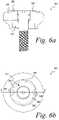
- FIG. 6 ais a top view of another embodiment of a healing abutment
- FIG. 6 bis a longitudinal cross-sectional view of the healing abutment shown in FIG. 6 a;
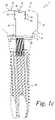
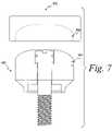
- FIG. 7is an exploded view of another embodiment of the present application.
- FIG. 8is a side view of a method for stereophotographic imaging
- FIGS. 9 a - 9 pare top views of a plurality of healing abutments having a binary-type system of information markers
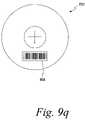
- FIG. 9 qis a top view of a healing abutment having a bar code information marker
- FIG. 10is a perspective view of a coordinate system of one embodiment of the present invention.
- FIG. 11is a perspective view of a stone model of an impression of a mouth used with one embodiment of the present invention.
- FIG. 12is a perspective view of a 3-D CAD model of the stone model of FIG. 11 ;
- FIG. 13is a perspective view of an altered 3-D CAD model of FIG. 12 with the healing abutments removed from the CAD model;
- FIG. 14is a perspective view of an altered 3-D CAD model of FIG. 13 with a custom abutment added in the CAD model;
- FIG. 15is a perspective view of a 3-D CAD model with an overmold attached over the custom abutment and the adjoining teeth;
- FIG. 16is a perspective view of a rapid prototype of the overmold shown in the 3-D CAD model of FIG. 15 including an implant analog and an abutment;
- FIG. 17is a perspective view of an altered stone model of FIG. 11 with the overmold of FIG. 16 attached;
- FIG. 18is a perspective view of the altered stone model of FIG. 17 with the overmold removed and the implant analog placed in the stone model and the patient-specific abutment connected to the implant analog;
- FIG. 19 ais a perspective view of an embodiment of an altered stone model of a mouth with abutments removed;
- FIG. 19 bis a perspective view of an alternative embodiment of an altered stone model of a mouth with abutments removed;
- FIG. 20is a perspective view of a 3-D CAD model of a custom abutment and implant analog placed within a mouth.
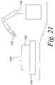
- FIG. 21is a schematic representation of a robot manipulator system adapted to place an implant analog into a stone model according to another embodiment of the present invention.
- the healing abutment 10 of one embodiment of the present inventionhas a main body 15 with a generally circular cross-sectional shape, a first tapered section 17 , a boundary 19 , a second tapered section 21 , an end surface 23 , a hex socket 25 and dimensions that are generally suitable for replicating the emergence profile of a natural tooth.
- the first tapered section 17extends downwardly from the main body 15 of the abutment 10 having a diameter at a boundary 19 that is generally larger than the implant (not shown).
- the boundary 19separates the first tapered section 17 from the second tapered section 21 that terminates in the end surface 23 .
- the second tapered section 21is at an angle with the central axis of the implant that is generally in the range from about 5 degrees to about 15 degrees, with 10 degrees being preferable.
- the second tapered section 21may be omitted such that the first tapered section 17 tapers directly to the diameter of the end surface 23 of the implant.
- the first tapered section 17may merge smoothly into the second tapered section 21 , without the distinct boundary 19 separating the two tapered sections 17 and 21 .
- the hexagonal orientation socket or hex 25is for mating with a hexagonal boss on the implant.
- the end surface 23has generally the same diameter as the seating surface of the implant.
- FIG. 1 bdiscloses the top view of the same healing abutment 10 shown in FIG. 1 a .
- the healing abutment 10has positive information markers 20 protruding from a top surface 29 of the healing abutment 10 .
- Each of the six positive information markers 20is disposed such that it aligns with the six corners of the underlying hex 25 .
- the six information markers 20may also correspond to the height of the healing abutment. For example, two information markers might correspond to a 2 mm tall healing abutment and four information markers might correspond to a healing abutment that is 4 mm tall. In these embodiments, the two or four information markers would still be at the corners of the underlying hex 25 so that the relative position of the hex is known.
- a socket 30 on the exposed surface of a head portion 40 of an attaching bolt 50is shaped to accept a wrench (not shown) for turning the attaching bolt 50 into the threaded bore of an implant 70 , as shown in FIG. 1 c . It is contemplated in accordance with the present invention that each of the healing abutments described herein and shown in the figures can be secured to an implant by means of an attaching bolt, as is known in the art.
- An 0 -ring 60 carried on the head portion 40 of the attaching bolt 50fills an annular gap left between the head and the entrance section near the outermost (widest) opening in the entrance section.
- a healing abutment 100 of FIG. 2 acomprises many of the same features as the healing abutment 10 shown in FIG. 1 a . Dashed lines 125 in FIG. 2 b correspond to the underlying hex 125 of the healing abutment 100 in FIG. 2 a .
- a top surface 129includes negative information markers (recesses) 120 that are displayed in FIG. 2 a as dimples extending below the top surface 129 of the healing abutment 100 .
- the top surface 129 of the healing abutment 100also possesses six notches 130 that are machined into the corners.
- the top surface 129is generally flat and merges into a rounded shape at the periphery of the healing abutment 100 .
- the notches 130are used, for example, to determine the identification of the underlying implant hex position 125 or the height of the healing abutment or the diameter of the healing abutment. This embodiment is not limited to comprising six notches in the top surface 129 of the healing abutment 100 . It is also contemplated that one embodiment of the present invention may possess four notches or even two notches for indicative purposes. Furthermore, it is contemplated that the information marker and notch approach could be combined or modified to provide information regarding the underlying implant seating surface diameter and implant hex angulation.
- a healing abutment 200 shown in FIGS. 3 a and 3 bdisplays four positive information markers 220 shown to, for example, indicate a 4 mm tall healing abutment 200 . It is contemplated that the number of information markers 220 could decrease or increase depending on the height of the healing abutment 200 or another variable that the information markers have been designated to correspond.
- the positive information markers 220also define a corresponding one of the six flat surfaces of an underlying hex 225 . Furthermore, dashed lines 225 in FIG. 3 b correspond directly to the underlying hex 225 .
- Two notches 230have also been etched or machined onto a top surface 229 of the healing abutment of FIG. 3 b . These notches may indicate the diameter of the implant's seating surface.
- Lines 240are scribed on the top surface 229 of the healing abutment 200 .
- the lines 240are used to provide positioning or other information to the dentist or laboratory.
- the lines 240indicate the diameter of the healing abutment (e.g., 4 mm).
- the number of the positive information markers 220indicates the height of the healing abutment 200 .
- the position of the positive information markers 220indicates the orientation of the hex 225 that is the orientation of the hexagonal boss on the implant.
- the notches 230indicate the diameter of the seating surface of the implant.
- the lines 240indicate the diameter of the healing abutment 200 .
- a top surface 329 of the healing abutment 300 of FIGS. 4 a and 4 bcomprises an etched or machined hex 335 .
- Comers 322 of the etched hex 335correspond directly to the position of the corners of an underlying hex 325 shown in FIG. 4 a . It is contemplated in accordance with one embodiment of the present invention that further information markers may be added to the healing abutment for the dentist or laboratory to ascertain different heights or diameters.
- a top surface 429 of a healing abutment 400 shown in FIGS. 5 a and 5 bcontains an etched or machined triangle 435 .
- Dashed lines 425 in FIG. 5 bindicate the location of an underlying hex 425 .
- Comers 422 of the etched triangle 435correspond to three of the six corners of the underlying hex 425 .
- two negative information markers 420are shown in FIG. 5 b . As above, it is contemplated in accordance with the present invention that fewer than six information markers may exist to account for differing heights or diameters of the healing abutments.
- FIGS. 6 a and 6 bAnother embodiment of the present invention is shown in FIGS. 6 a and 6 b .
- the healing abutment 500 displayed in FIGS. 6 a and 6 bis a shorter version of the healing abutment 10 shown in FIGS. 1 a and 1 b .
- Two positive information markers 520are shown in FIG. 6 b to identify the height of the healing abutment 500 .
- Dashed lines 525 of the healing abutment 500correspond with the location and orientation of the underlying hex 525 .
- Two notches 530are also shown in a top surface 529 of this embodiment of the present invention to show the orientation of two of the underlying flats of the underlying hex 525 .
- a numeral “ 4 ” at 537is located on the top surface 529 of the healing abutment 500 to indicate, for example, the diameter of the healing abutment 500 .
- the numeral “ 4 ” at 537corresponds to a healing abutment 500 with a diameter of 4 mm. It is contemplated in accordance with the present invention that other numerals could be placed on the top surface 529 of the healing abutment 500 to indicate other healing abutment diameters. Further, it is also contemplated that the numeral could represent the height of the healing abutment or the diameter of the underlying implant.
- an impression of the mouthis made with only the healing abutments as described herein and without the use of an impression coping.
- a model of the impressionis poured with, for example, die stone. Since the information markers are disposed on the top and/or side of the healing abutment, the laboratory has all necessary information to define the gingival aperture, the implant size and the orientation of the underlying hex. This enables the laboratory to quickly prepare the permanent components.
- the system of the present inventionalso allows the maintenance of the soft-tissue surrounding the healing abutment where in prior systems the soft tissue would close once the healing abutment was removed. The system spares the patient from the pain of removing the healing abutment.
- FIG. 8shows stereophotographic imaging, one method used for scanning. Stereophotography with a camera 703 is performed directly on the mouth cavity 705 of the patient 707 . A clinician can photograph implants and other components that have been placed into or adjacent the patient's jawbone 709 .
- the scanned informationis then transferred into a graphical imaging program for analysis.
- the graphical imaging software programdue to the information markers on the surface of the healing abutment, can perform a wide variety of functions.
- the graphical imaging programcan scan an opposing cast in order to develop an opposing occlusal scheme and relate this information back to the primary model. This feature is extremely important because many clinical patients have implants in both maxillary and mandibular locations.
- the graphical imaging software programis capable of generating a three-dimensional image of the emergence profile contours used on the healing abutment. If the implant is not placed in the desired esthetic location, the software program relocates the position of the restoration emergence through the soft tissue.
- the graphical imaging software programis also able to accurately relate the gingival margin for all mold, model, implant and abutment dimensions.
- the softwarecreates a transparent tooth outline for superimposition within the edentulous site.
- the occlusal outline of the “ghost” toothshould, if possible, be accurate and based on the scanned opposing occlusal dimensions. It is contemplated in accordance with the present invention that an occlusal outline is created by scanning a wax-up in order to maintain a proper plane of occlusion and healing abutment height.
- the software programsubtracts a given dimension from the mesial, distal, buccal, lingual, and occlusal areas of the superimposed tooth dimension. This allows for an even reduction of the healing abutment during fabrication to allow for proper thickness of the overlying materials (e.g., gold, porcelain, targis, etc.).
- the graphical imaging software programalso incorporates angulation measurements into the custom abutment and subsequently calculates the dimensions of the prosthesis that are checked and modified, if necessary, by a laboratory technician. Each of the features is analyzed and determined from the different information markers that exist on the healing abutments of the present invention.
- the final dimensional information determined by the graphical imaging computer programis transferred from the computer to a milling machine (e.g., a 5-axis milling machine) to fabricate the custom abutment.
- a milling machinee.g., a 5-axis milling machine
- the custom abutmentcan be fashioned from gold or titanium or other similar metals or composites.
- a custom milled copingcan then be fabricated.
- the custom milled copingcan be formed from titanium, plastic, gold, ceramic, or other similar metals and composites.
- FIG. 7shows the exploded view of another embodiment of the present invention.
- a cap 602is placed on a healing abutment 600 and later removed during the process of taking the impression of the healing implant and surrounding features of the patient's mouth. It is contemplated in accordance with the present invention that the cap 602 could be formed from plastic or metal or a composite material.
- notches 604are formed in the side(s) of the healing abutment 600 . These notches correspond to notches 606 that have been preformed in the cap 602 .
- the cap 602When the cap 602 is placed onto the healing abutment 600 , the cap only fits snugly and properly if the number of notches 606 in the cap 602 corresponds exactly to the number of notches 604 in the side wall(s) of the healing abutment. It is contemplated in accordance with the present invention that there could be many less or more notches than is depicted in FIG. 7 . These notches correspond to information parameters such as healing abutment height, healing abutment and/or implant diameter and other parameters as listed above.
- the cap 602is securely placed over the top of the healing abutment 600 .
- the impression materialis then placed over the top of the cap 602 .
- the impressionis then either scanned in the patient's mouth or the impression material (with the cap 602 ) is then scanned and the process continues as described above.
- FIGS. 9 a - 9 pdepict yet another embodiment of the present invention.
- FIGS. 9 a - 9 pshow the top view of a plurality of healing abutments, each of which has four marking locations on the top surface of the healing abutment.
- a markeris either present or absent in each of the four marking locations, and the presence or absence can be interpreted either visually or by a scanning device.
- the markers in the marking locationspermit identification of healing abutment characteristics, such as dimensions of the healing abutment.
- the four rowscorrespond to four different healing abutment heights (e.g., 3 mm, 4 mm, 6 mm, and 8 mm).
- the four columns of the coding keycorrespond to four different diameters of the healing abutment seating surfaces (e.g., 3.4 mm, 4.1 mm, 5.0 mm, and 6.0 mm). Accordingly, sixteen unique healing abutments are present.
- each of the healing abutmentshas from zero to four information markers located in the four marking locations. As shown in FIGS. 9 a - 9 p , the marking locations extend radially from a central region of the healing abutment to the outer region of the top surface of the healing abutments (i.e., at locations of 12 o'clock, 3 o'clock, 6 o'clock, and 9 o'clock).
- a binary-coded systemexists as an array of digits, where the digits are either “1” or “0” that represent two states, respectively, ON and OFF. For each marking location, the presence of a marker (“ON”) is a 1 and the absence of a marker (“OFF”) is a 0.
- the determination of the sets of 1's and 0's derived from the information markersprovide information on the height of the healing abutment and the diameter of the seating surface of the attached implant.
- the information markers shown in FIGS. 9 a - 9 pare in the form of grooves having rounded cross-sections.
- the present inventionprovides that the cross-section of these grooves can be rectangular, triangular, or various other shapes.
- the grooved marking locationsproduce a protruding “mound”-like element in the impression.
- This impressionis then scanned so that identifying features regarding the healing abutment can be obtained.
- a model of the patient's mouthis created from the impression such that the markings are again grooves in the model that substantially replicate the grooves in the healing abutments.
- the markerscould also be protrusions instead of grooves.
- markers not producing features in impression materialsuch as etched or laser marking, may also be used.
- FIG. 9 aillustrates a top view of a healing abutment 801 that includes orientation pick-ups 802 .
- These orientation pick-ups 802are also present in each of the healing abutments shown in FIGS. 9 b - 9 p .
- the most counterclockwise of the orientation pick-ups 802i.e., the horizontal pick-up at the lower region of FIGS. 9 a - 9 p
- the orientation pick-ups 802are a pair of bevels on the sides of the healing abutments in FIGS. 9 a - 9 p .
- the orientation pick-ups 802can be grooves or protruding ridges, as well.
- the orientation pick-ups 802serve a second function in that they dictate which of the four marking locations is the first marking location.
- the other three marking locationsare then read in clockwise order, proceeding from the most counterclockwise pick-up 802 to the other three marking locations on the top surface of the healing abutment.
- the information marker at 6 o'clockis the first digit in the binary code
- the information marker at 9 o'clockis the second digit in the binary code
- the information marker at 12 o'clockis the third digit in the binary code
- the information marker at 3 o'clockis the fourth digit in the binary code.
- the position of the orientation pick-ups 802allows for the determination of the position of one of the hex flats of the healing abutment (and, likewise, one of the hex flats on the implant), and also the starting point to check for the presence or absence of information markers.
- the binary code for the healing abutment 801is 0000, indicating that no grooved marker is present in any of the four predetermined positions. Since the coding key is preset (on a chart or in computer software), the binary code 0000 indicates that the healing abutment 801 is a resident of first row and first column of the matrix depicted by FIG. 9 , having a height of 3 mm and a seating surface diameter of 3.4 mm.
- the three distinct pieces of information obtained from the top of the healing abutmentallow the clinician or laboratory to know (i) the orientation of the hex of the implant, (ii) the height of the healing abutment (i.e., the location of the implant's seating surface below the healing abutment), and (iii) the seating surface diameter of the healing abutment (or the size of the implant's seating surface).
- the healing abutment 806 in FIG. 9 bpossesses a binary code of 0100because only one information marker 807 is present in the second marking location.
- the healing abutment 806is 3 mm in height and has a seating surface diameter of 4.1 mm.
- the two healing abutments 811 , 816 in FIGS. 9 c , 9 dhave binary codes of 1000 and 1100, respectively.
- Healing abutment 811has an information marker 812 in the first marking location, while healing abutment 816 has information markers 817 , 818 in the first two locations.
- the unique characteristics of these two healing abutmentsare known.
- healing abutments 821 , 826 , 831 , 836 shown in FIGS. 9 e - 9 h and having heights of 4 mm, but with varying seating surface diameters,would be interpreted as having binary codes 0010, 0110, 1010, and 1110, respectively.
- Healing abutment 821has one information marker 822 present in the third marking location, thus resulting in a binary code of 0010, which is indicative of a healing abutment height of 4 mm and a seating surface diameter of 3.4 mm.
- healing abutment 826 with information markers 827 , 828 , healing abutment 831 with information markers 832 , 833 , and healing abutment 836 with information markers 837 , 838 , 839allow determinations of the unique characteristics of these healing abutments.
- healing abutments 841 , 846 , 851 , 856 shown in FIGS. 9 i - 91 and having heights of 6 mm, but with varying seating surface diameters,would be interpreted as having binary codes 0001, 0101, 1001, and 1101, respectively.
- Healing abutment 841has one information marker 842 present in the fourth marking location, thus resulting in a binary code of 0001, which is indicative of a healing abutment height of 6 mm and a seating surface diameter of 3.4 mm.
- healing abutment 846 with information markers 847 , 848 , healing abutment 851 with information markers 852 , 853 , and healing abutment 856 with information markers 857 , 858 , 859allow determinations of the unique characteristics of these healing abutments.
- healing abutments 861 , 866 , 871 , 876 shown in FIGS. 9 m - 9 p and having heights of 8 mm, but with varying seating surface diameters,would be interpreted as having binary codes 0011, 0111, 1011, and 1111, respectively.
- Healing abutment 861has two information markers 862 , 863 , which is indicative of a healing abutment height of 8 mm and a seating surface diameter of 3.4 mm.
- healing abutment 866 with information markers 867 , 868 , 869 , healing abutment 871 with information markers 872 , 873 , 874 , and healing abutment 876 with information markers 877 , 878 , 879 , 880allow determinations of the unique characteristics of these healing abutments.
- the matrix of the sixteen healing abutments in FIGS. 9 a - 9 pshow four implant seating surface diameters and four heights
- the matrixcould include other physical characteristics of the healing abutment.
- the maximum diameter of the healing abutmentcould be information obtainable through the binary-coded system.
- the type of fitting on the healing abutment and, thus, the implanti.e., internal hex or external hex
- Information unrelated to the healing abutment, but related to only the implant,could be used.
- the manufacturer of the implantcould be noted.
- information regarding the type of screw that mates with the internally thread bore of the implantcould be provided.
- FIGS. 9 a - 9 pdemonstrate the ability of the four digit, binary-coded system to provide two physical characteristics of the healing abutment, it could provide three or more physical characteristics. For example, two seating surface sizes, four heights, and two maximum diameters would provide sixteen unique healing abutments. If more information were needed, a fifth marking location could be added to provide the opportunity for displaying thirty-two physical characteristics of the healing abutments and/or implant. And, while one marking location has been shown with marker, it is possible to have two or more markers in each marking location. For example, one circumferential groove and one radial groove within one location could represent two digits of a binary system. Alternatively, having two widths possible for each groove could provide additional indicia representative of certain information about the healing abutment.
- the set of healing abutmentscould include components shaped like the various teeth, and the information markers could provide the information regarding which tooth shape is present on the healing abutment.
- a setmay include four types of molar-shaped healing abutments, four types of bicuspid-shaped healing abutments, four types of incisor-shaped healing abutments and four types of round abutments.
- the four information marker locations on each component in the setprovide the information to determine which one of the sixteen healing abutments is being used.
- the present inventionalso covers a set of eight unique healing abutments (as opposed to the sixteen shown) requiring only three marking locations.
- the computer software and/or the visual chart in this situationwould identify these eight unique healing abutments through binary codes possessing three digits.
- the potential binary codes corresponding to an ON or OFF determination at the three marking locationsare 000, 100, 010, 001, 110, 101, 011, and 111.
- the potential binary codes in a four healing abutment matrixare 00, 10, 01, and 11.
- the orientation of the hexis known from the location of the orientation pick-ups 802 and, via the binary code, the abutment height and the seating surface of the healing abutment is known.
- Other information regarding the healing abutment and the attached implantcan also be determined by adding other markers of the type previously shown.
- the bar code 894can be located on the top surface on the healing abutment 892 such that it can be scanned or read easily.
- the bar code 894would provide the same type of information described above with respect to the information markers.
- the computer softwarewhen scanning techniques are used to learn of the information on the top of the healing abutment, the computer software is able to determine the position and orientation of the implant 900 relative to the adjacent teeth.
- the position of the implant 900is defined in a Cartesian coordinate system having “X,” “Y,” and “Z” axes.
- the common pointis at the intersection of the centerline of the implant and a plane 920 representing the seating surface 925 of the implant 900 .
- the information markersassist in determining the height of the healing abutment above the implant.
- This heightcan be used to identify the zero point on the “Z” axis, which is in the plane 920 containing the seating surface 925 of the implant 900 .
- the “Y” axis 910is within the plane 920 representing the seating surface 925 with the positive “Y” direction as close to the direction of facial to buccal as possible.
- the “X” axis 915is in the plane 920 and is perpendicular to an implant hex face.
- the width of the seating surface 925 in the plane 920is known, as is the width of the healing abutment emerging through the gingiva.
- the emergence profile of the artificial toothis known, as well.
- FIG. 11a perspective view of a stone cast 1000 of a mouth of a patient is shown with a stone-cast model of a healing abutments 1002 which has configurations on its upper surface that corresponds to the healing abutments previously described.
- the stone cast 1000is made from an impression of the mouth as previously described.
- the stone cast 1000is prepared, it is scanned using a scanning technique previously described, the scanned data is transferred into a graphical imaging program, such as a Computer Aided Design (“CAD”) program so that a three-dimensional (“3-D”) CAD model 1100 of the stone cast 1000 ( FIG. 11 ) is created, as shown in FIG. 12 .
- CADComputer Aided Design
- the CAD model 1100 ( FIG. 12 ) of the stone cast 1000 ( FIG. 11 )is modified to create a first modified CAD model 1200 that removes the healing abutment 1002 ( FIG. 11 ) so that the position of an implant 1202 , or the top surface of an implant, underlying the healing abutment 1002 ( FIG. 11 ) is displayed.
- the CAD programis additionally used to design a custom, patient specific, abutment adapted to attach to the implant 1202 .
- the custom abutmentsupports a final prosthesis, often referred to as a crown.
- a modified version of the stone model 1000is used to design the crown to fit between the adjacent teeth based on the specific dimensions and conditions of a patient's mouth. Thus, obtaining an accurate position of the dental implant is critical to designing an accurate crown.
- the design of the custom abutmentis input into a precision manufacturing device, such as a CNC milling machine, to create the custom abutment from a blank of metal, usually titanium, or a titanium alloy, or from a ceramic material.
- a CAD model of a custom abutment 1402is shown located between a CAD model of the adjacent teeth 1404 that has been created by scanning the stone model 1000 .
- an overmold 1502is created, as shown in FIG. 15 .
- the overmold 1502fits over the custom abutment 1402 and the adjacent teeth 1404 in the 3-D CAD model 1400 .
- the overmold 1502is adapted to fit over a stone model of the patient's teeth to allow an actual custom abutment 1604 ( FIG. 18 ) to be positioned in substantially the identical location and orientation as the custom abutment 1402 in the 3-D CAD model 1400 .
- the CAD programallows a rapid prototype overmold 1602 ( FIG. 16 ) corresponding to the 3-D CAD model of the overmold 1502 to be created using rapid prototype equipment. It is contemplated that many rapid prototyping techniques may be utilized with the present invention such as: stereolithography, laminated-object manufacturing, selective laser sintering, solid ground curing, or other known rapid prototyping processes.
- the 3-D CAD model of the overmold 1502is used by the equipment controlling the rapid prototype equipment to create the rapid prototype overmold 1602 .
- a rapid prototype assembly 1600is shown having the rapid prototype overmold 1602 , a custom abutment 1604 , and an implant analog 1606 .
- the rapid prototype overmold 1602is adapted to receive the custom abutment 1604 via a snap-fit connection created by snapping the overmold 1602 over an edge of the custom abutment 1604 .
- a press fitmay be used to secure a custom abutment to a rapid prototype overmold by using an interference fit.
- the custom abutment 1604is secured to the implant analog 1606 using a screw.
- the custom abutment 1604 ( FIG. 18 ) produced on the precision manufacturing devicemust then be placed within an altered stone model 1700 as shown in FIG. 17 , so that the crown may be created.
- the altered stone model 1700has had the healing abutment 1002 from the stone cast 1000 ( FIG. 11 ) removed, so that an opening 1702 is present where the healing abutment 1002 from the stone cast 1000 ( FIG. 11 ) had been located.
- the opening 1702is of a sufficient size so as to receive the implant analog 1606 .
- a gap 1706or a hole large enough to receive an implant analog, exists in the stone model 1700 between the implant analog 1606 and the walls defining the opening 1702 .
- the rapid prototype assembly 1600is placed over the stone model 1700 , positioning the custom abutment 1604 and the implant analog 1606 as in the 3-D CAD model.
- the gap 1706is then filled with a securing material, such as epoxy, to secure the implant analog 1606 to the stone model 1700 .
- a securing materialsuch as epoxy
- the implant analog 1606is properly positioned within the stone model 1700 , at substantially the same location as the implant in the patient's mouth relative to the teeth adjacent to the implantation site.
- the implant analog 1606 and the custom abutment 1604may be removed from the rapid prototype overmold 1602 , as shown in FIG. 18 .
- the final prosthesismay then be created using the stone model 1700 having the properly positioned implant analog 1606 and custom abutment 1604 .
- the same stone modelmay be used for a scanning process to make the patient specific custom abutment 1604 and for receiving an implant analog 1606 for mating with the custom abutment 1604 to develop a final prosthesis.
- an implant analogis placed within a stone model using a robot manipulator.
- a stone cast 1000 of a mouth of a patientis produced from taking an impression of the patient's, mouth.
- the stone castis scanned to generate a 3-D CAD model 1100 of the stone cast 1000 .
- the CAD programis used to design a custom abutment 1604 .
- the custom abutment 1604is produced on a precision manufacturing device using information from the CAD program.
- a modified stone cast 1900is created by removing a section of the stone cast 1000 that contains the healing abutment 1002 ( FIG. 11 ).
- the CAD program used to generate the custom abutment 1604is used to generate a 3-D CAD model containing a custom abutment having an implant analog attached.
- a 3-D CAD model 2000exists where the proper position of the implant analog 2002 relative to adjacent teeth 2004 is created as shown in FIG. 20 .
- the relative position of the implant analogs 2002 and the adjacent teeth 2004may be generated.
- a common base plate 2106FIG. 21
- the robot manipulator 2100( FIG. 21 ) is located at a known position relative to the ase plate 2106 ( FIG. 21 ).
- a scannermeasures an X, Y, and Z position of the healing abutment 1002 in the stone cast 1000 relative to axes on the base plate 2106 , also referred to as the base plate 2106 origin.
- an exact location of an implant analog 2102( FIG. 21 ) may be determined.
- this position informationis input to a robot manipulator.
- the robot manipulator 2100uses the relative position information to place an implant analog 2102 into a securing material 2104 , such as epoxy, located on the modified stone cast 1900 where the healing abutments had been located, as shown schematically in FIG. 21 .
- the robot manipulator 2100is able to accurately place the implant analog 2102 in the securing material 2104 , such that the position of the implant analog 2102 within the modified stone cast 1900 is substantially identical to the position of the implant analog 2002 within the 3-D CAD model 2000.
- the robot manipulatormay instead be a multiple handed robot manipulator adapted to drill a hole 1902 in a stone cast 1901 (as shown in FIG. 19 b ) with a first hand, and place an implant analog in the hole with a second hand.
- a scanning abutmentmay be placed into a stone model before a scan is performed.
- a first stone model of a patient's mouthwould be made, and a portion of the first stone model corresponding to a healing abutment would be removed and replaced with a scanning abutment containing a variety of markings as previously described.
- a scanwould then be performed of the first stone model containing the scanning abutment, and a 3-D CAD model of the patient's mouth would be created. The 3-D CAD model would then be used as previously described.
Landscapes
- Health & Medical Sciences (AREA)
- General Health & Medical Sciences (AREA)
- Animal Behavior & Ethology (AREA)
- Oral & Maxillofacial Surgery (AREA)
- Dentistry (AREA)
- Epidemiology (AREA)
- Life Sciences & Earth Sciences (AREA)
- Veterinary Medicine (AREA)
- Public Health (AREA)
- Engineering & Computer Science (AREA)
- Optics & Photonics (AREA)
- Physics & Mathematics (AREA)
- Manufacturing & Machinery (AREA)
- Dental Prosthetics (AREA)
- Dental Tools And Instruments Or Auxiliary Dental Instruments (AREA)
- Prostheses (AREA)
Abstract
Description
Claims (9)
Priority Applications (9)
| Application Number | Priority Date | Filing Date | Title |
|---|---|---|---|
| US11/585,705US7661956B2 (en) | 2005-10-24 | 2006-10-24 | Methods for manufacturing dental implant components |
| US12/070,922US8257083B2 (en) | 2005-10-24 | 2008-02-22 | Methods for placing an implant analog in a physical model of the patient's mouth |
| US12/650,169US8011925B2 (en) | 2005-10-24 | 2009-12-30 | Methods for manufacturing dental implant components |
| US13/053,424US8690574B2 (en) | 2005-10-24 | 2011-03-22 | Methods for placing an implant analog in a physical model of the patient's mouth |
| US13/554,936US8998614B2 (en) | 2005-10-24 | 2012-07-20 | Methods for placing an implant analog in a physical model of the patient's mouth |
| US14/640,557US10307227B2 (en) | 2005-10-24 | 2015-03-06 | Methods for placing an implant analog in a physical model of the patient's mouth |
| US16/397,381US11219511B2 (en) | 2005-10-24 | 2019-04-29 | Methods for placing an implant analog in a physical model of the patient's mouth |
| US17/553,400US11896459B2 (en) | 2005-10-24 | 2021-12-16 | Methods for placing an implant analog in a physical model of the patient's mouth |
| US18/439,000US12329608B2 (en) | 2005-10-24 | 2024-02-12 | Methods for placing an implant analog in a physical model of the patient's mouth |
Applications Claiming Priority (2)
| Application Number | Priority Date | Filing Date | Title |
|---|---|---|---|
| US72950605P | 2005-10-24 | 2005-10-24 | |
| US11/585,705US7661956B2 (en) | 2005-10-24 | 2006-10-24 | Methods for manufacturing dental implant components |
Related Child Applications (2)
| Application Number | Title | Priority Date | Filing Date |
|---|---|---|---|
| US12/070,922Continuation-In-PartUS8257083B2 (en) | 2005-10-24 | 2008-02-22 | Methods for placing an implant analog in a physical model of the patient's mouth |
| US12/650,169DivisionUS8011925B2 (en) | 2005-10-24 | 2009-12-30 | Methods for manufacturing dental implant components |
Publications (2)
| Publication Number | Publication Date |
|---|---|
| US20070092854A1 US20070092854A1 (en) | 2007-04-26 |
| US7661956B2true US7661956B2 (en) | 2010-02-16 |
Family
ID=37968405
Family Applications (2)
| Application Number | Title | Priority Date | Filing Date |
|---|---|---|---|
| US11/585,705Active2028-07-15US7661956B2 (en) | 2005-10-24 | 2006-10-24 | Methods for manufacturing dental implant components |
| US12/650,169Active2027-03-17US8011925B2 (en) | 2005-10-24 | 2009-12-30 | Methods for manufacturing dental implant components |
Family Applications After (1)
| Application Number | Title | Priority Date | Filing Date |
|---|---|---|---|
| US12/650,169Active2027-03-17US8011925B2 (en) | 2005-10-24 | 2009-12-30 | Methods for manufacturing dental implant components |
Country Status (9)
| Country | Link |
|---|---|
| US (2) | US7661956B2 (en) |
| EP (2) | EP3175819A1 (en) |
| JP (1) | JP5021660B2 (en) |
| KR (1) | KR101214950B1 (en) |
| CN (1) | CN101370441B (en) |
| AU (1) | AU2006306462B2 (en) |
| CA (1) | CA2626901C (en) |
| IL (2) | IL190541A (en) |
| WO (1) | WO2007050436A2 (en) |
Cited By (26)
| Publication number | Priority date | Publication date | Assignee | Title |
|---|---|---|---|---|
| US20080153067A1 (en)* | 2005-10-24 | 2008-06-26 | Biomet 3I, Inc. | Methods for placing an implant analog in a physical model of the patient's mouth |
| US20090130630A1 (en)* | 2007-11-16 | 2009-05-21 | Suttin Zachary B | Components for Use with a Surgical Guide for Dental Implant Placement |
| US20100086899A1 (en)* | 2007-01-03 | 2010-04-08 | Etkon Centrum Für Dentale Cad/Cam-Tecnologie Ag | Method concerning the modelling and production of a set of artificial teeth |
| US20100303316A1 (en)* | 2009-05-27 | 2010-12-02 | James R. Glidewell Dental Ceramics, Inc. | Mehod of designing and fabricating patient-specific restorations from intra-oral scanning of a digital impression |
| US20110019155A1 (en)* | 2009-07-24 | 2011-01-27 | Optimet, Optical Metrology Ltd. | Method and Apparatus for Real-Time Projection onto an Object of Data Obtained from 3-D Measurement |
| US20110129792A1 (en)* | 2008-04-15 | 2011-06-02 | Berckmans Iii Bruce | Method of creating an accurate bone and soft-tissue digital dental model |
| US20110200968A1 (en)* | 2010-02-17 | 2011-08-18 | Procerex Dental Lab Llc | System and method for fabricating a dental healing abutment |
| US20120296613A1 (en)* | 2009-11-19 | 2012-11-22 | Bastian Kirchner | Method and system for designing a dental restoration |
| US8414296B2 (en) | 2008-04-16 | 2013-04-09 | Biomet 3I, Llc | Method for pre-operative visualization of instrumentation used with a surgical guide for dental implant placement |
| US20130089837A1 (en)* | 2010-06-15 | 2013-04-11 | Materialise Dental Nv | Custom healing cap for dental implantology and method for design and manufacturing thereof |
| US8612037B2 (en) | 2005-06-30 | 2013-12-17 | Biomet 3I, Llc | Method for manufacturing dental implant components |
| US20140272801A1 (en)* | 2011-10-07 | 2014-09-18 | Heraeus Kulzer Gmbh | Lab analog with indexing for insertion into plastic models with corresponding counter-indexing |
| US8882508B2 (en) | 2010-12-07 | 2014-11-11 | Biomet 3I, Llc | Universal scanning member for use on dental implant and dental implant analogs |
| US8926328B2 (en) | 2012-12-27 | 2015-01-06 | Biomet 3I, Llc | Jigs for placing dental implant analogs in models and methods of doing the same |
| US8944818B2 (en) | 2011-05-16 | 2015-02-03 | Biomet 3I, Llc | Temporary abutment with combination of scanning features and provisionalization features |
| US9089382B2 (en) | 2012-01-23 | 2015-07-28 | Biomet 3I, Llc | Method and apparatus for recording spatial gingival soft tissue relationship to implant placement within alveolar bone for immediate-implant placement |
| US9452032B2 (en) | 2012-01-23 | 2016-09-27 | Biomet 3I, Llc | Soft tissue preservation temporary (shell) immediate-implant abutment with biological active surface |
| US9668834B2 (en) | 2013-12-20 | 2017-06-06 | Biomet 3I, Llc | Dental system for developing custom prostheses through scanning of coded members |
| US9687327B2 (en) | 2013-03-14 | 2017-06-27 | Anthony Prestipino | Apparatuses and methods for making a final hybrid prosthesis to be attached to dental implants |
| US9700390B2 (en) | 2014-08-22 | 2017-07-11 | Biomet 3I, Llc | Soft-tissue preservation arrangement and method |
| US9763758B2 (en) | 2011-01-13 | 2017-09-19 | Align Technology, Inc. | Virtual and physical dental models of dental surfaces and analog socket structure of a dental implant and related procedures |
| US10449018B2 (en) | 2015-03-09 | 2019-10-22 | Stephen J. Chu | Gingival ovate pontic and methods of using the same |
| US10813729B2 (en) | 2012-09-14 | 2020-10-27 | Biomet 3I, Llc | Temporary dental prosthesis for use in developing final dental prosthesis |
| US20210282901A1 (en)* | 2017-06-20 | 2021-09-16 | Euroteknika | Assembly for dental restoration |
| US11219510B2 (en) | 2015-11-20 | 2022-01-11 | Nobel Biocare Services Ag | Healing cap with scannable features |
| US11219511B2 (en) | 2005-10-24 | 2022-01-11 | Biomet 3I, Llc | Methods for placing an implant analog in a physical model of the patient's mouth |
Families Citing this family (58)
| Publication number | Priority date | Publication date | Assignee | Title |
|---|---|---|---|---|
| JP4481279B2 (en)* | 2006-08-17 | 2010-06-16 | 株式会社ジーシー | Data preparation support program for abutment facing surface machining of dental prosthesis |
| WO2008051129A1 (en) | 2006-10-27 | 2008-05-02 | Nobel Biocare Services Ag | A dental impression tray for use in obtaining an impression of a dental structure |
| EP2079394B1 (en) | 2006-10-27 | 2016-05-18 | Nobel Biocare Services AG | Method and apparatus for obtaining data for a dental component and a physical dental model |
| US8206153B2 (en) | 2007-05-18 | 2012-06-26 | Biomet 3I, Inc. | Method for selecting implant components |
| US20100255445A1 (en)* | 2007-10-03 | 2010-10-07 | Bernard Gantes | Assisted dental implant treatment |
| WO2009046391A1 (en)* | 2007-10-03 | 2009-04-09 | Bernard Gantes | Assisted dental implant treatment |
| TWI463969B (en)* | 2007-10-22 | 2014-12-11 | Design method of support tooth | |
| US20090254299A1 (en)* | 2008-04-04 | 2009-10-08 | Optimet, Optical Metrology Ltd. | Dental Prosthesis Fabrication Based on Local Digitization of a Temporary |
| US8509932B2 (en) | 2008-07-17 | 2013-08-13 | Cadent Ltd. | Methods, systems and accessories useful for procedures relating to dental implants |
| KR101124467B1 (en)* | 2008-12-31 | 2012-03-15 | 주식회사 사이버메드 | Surgical guide and surgical guide assembly |
| SI2385832T1 (en)* | 2009-01-08 | 2015-10-30 | Curis, Inc. | Phosphoinositide 3-kinase inhibitors with a zinc binding moiety |
| KR101026775B1 (en)* | 2009-02-06 | 2011-04-11 | 오스템임플란트 주식회사 | Abutment for implant |
| KR101697162B1 (en)* | 2009-02-26 | 2017-01-17 | 노벨 바이오케어 서비시스 아게 | Device for indicating the position and orientation of a dental implant |
| EP2254068B1 (en)* | 2009-05-18 | 2020-08-19 | Nobel Biocare Services AG | Method and system providing improved data matching for virtual planning |
| KR100950022B1 (en)* | 2009-08-13 | 2010-03-29 | 송경준 | Index abutment for customizing abutment |
| JP5241740B2 (en)* | 2009-11-26 | 2013-07-17 | 寶▲玉▼生技股▲分▼有限公司 | How to make dentures after implant surgery |
| TW201117777A (en)* | 2009-11-26 | 2011-06-01 | Pou Yu Biotechnology Co Ltd | Design method for dental implant prosthetics |
| WO2011154149A2 (en)* | 2010-06-10 | 2011-12-15 | Straumann Holding Ag | Analog positioner |
| DE102010031018A1 (en)* | 2010-07-06 | 2012-01-12 | Sirona Dental Systems Gmbh | Method and clamping device for producing a dental surgical template |
| US8712733B2 (en)* | 2010-09-17 | 2014-04-29 | Biocad Medical, Inc. | Adjusting dental prostheses based on soft tissue |
| AU2015201244B2 (en)* | 2011-05-16 | 2017-02-23 | Biomet 3I, Llc | Temporary abutment with combination of scanning features and provisionalization features |
| KR101240357B1 (en)* | 2011-06-10 | 2013-03-07 | 정제교 | Rapid prototype of oral model assembly for fabricating intraoral appliance used for implant operation and method for fabricating intraoral appliance used for implant operation using the same |
| ES2371897B1 (en)* | 2011-10-14 | 2013-01-24 | Phibo Dental Solutions, S.L. | DENTAL MODELS AND DENTAL MODELS MANUFACTURING PROCEDURE. |
| US10016260B2 (en)* | 2012-01-10 | 2018-07-10 | Mark H. Blaisdell | Anatomical healing abutments, kits, and methods |
| US9895209B2 (en) | 2012-01-10 | 2018-02-20 | Mark H. Blaisdell | Casting jig including elongate handle for chair-side manufacture of customizable sculptable anatomical healing caps, and method for forming bis-acrylic crown |
| US11253345B2 (en) | 2012-01-10 | 2022-02-22 | Esthetic Implant Solutions, Llc | Methods for integrating scans including 3D cone beam scan for positioning of implant and fabrication of dental prosthesis |
| US10595970B2 (en) | 2012-01-10 | 2020-03-24 | Esthetic Implant Solutions, Llc | Bonding of soft gingival tissues with anatomical and other dental prostheses |
| US10709525B2 (en) | 2012-01-10 | 2020-07-14 | Esthetic Implant Solutions, Llc | Methods for taking an oral scan without requiring removal of a temporary healing abutment |
| US20220151742A1 (en) | 2012-01-10 | 2022-05-19 | Esthetic Implant Solutions, Llc | Methods for integrating scans including 3d cone beam scan for positioning of implant and fabrication of dental prosthesis |
| WO2013112586A1 (en)* | 2012-01-24 | 2013-08-01 | Smith & Nephew, Inc. | Porous structure and methods of making same |
| ES2383415B9 (en)* | 2012-02-20 | 2013-10-30 | Phibo Dental Solutions, S.L. | DENTAL PILLAR FOR THE SUPPORT OF DENTAL PROSTHESIS AND MANUFACTURING METHOD OF THE SAME |
| US9554880B2 (en)* | 2012-10-25 | 2017-01-31 | Zfx Gmbh | Reference member for determining a position of an implant analog |
| US8905757B2 (en) | 2012-12-03 | 2014-12-09 | E. Kats Enterprises Ltd. | Method and apparatus for measuring a location and orientation of a plurality of implants |
| DE102013203449A1 (en)* | 2013-02-28 | 2014-08-28 | Sirona Dental Systems Gmbh | Method and device for controlling a computer program by means of an intraoral scanner |
| US9801699B2 (en) | 2013-03-14 | 2017-10-31 | Devin Okay | Paired templates for placing dental implants and enhancing registration for denture prosthetics attached to the implants |
| ES2910276T3 (en)* | 2013-04-09 | 2022-05-12 | Biomet 3I Llc | Method of using scan data of a dental implant |
| EP2842493B1 (en) | 2013-08-30 | 2016-04-06 | Zfx GmbH | Intraoral reference body |
| WO2015071261A2 (en)* | 2013-11-12 | 2015-05-21 | 3Shape A/S | Method for designing attachment abutments for attaching dentures to the mandible and/or maxilla |
| WO2015111766A1 (en)* | 2014-01-22 | 2015-07-30 | 김도현 | Patient-customized abutment manufacturing method |
| US20160015483A1 (en) | 2014-04-30 | 2016-01-21 | Osseodyne Surgical Solutions, LLC. | Osseointegrative surgical implant |
| US9572638B1 (en) | 2014-06-02 | 2017-02-21 | Lloyd T. Anderson | Impression coping spacer and method of dental casting |
| KR101472570B1 (en) | 2014-06-05 | 2014-12-16 | 김희준 | Discriminating the direction and location of fixture healing abutment |
| EP3212118B1 (en) | 2014-10-29 | 2021-04-14 | Euroteknika | Wound-healing unit for a dental restoration |
| FR3042699B1 (en)* | 2015-10-27 | 2021-02-19 | Euroteknika | HEALING ELEMENT FOR A DENTAL RESTORATION |
| DE102016213399A1 (en)* | 2016-07-21 | 2018-01-25 | Sirona Dental Systems Gmbh | Surveying system and method for measuring an implant-implant situation |
| EP3506852B1 (en)* | 2016-08-31 | 2021-03-17 | Andy Boiangiu | Dental implant cover |
| CN106169603A (en)* | 2016-09-29 | 2016-11-30 | 珠海格力电器股份有限公司 | Battery generation method and system |
| FR3063884B1 (en) | 2017-03-20 | 2021-12-17 | Euroteknika | DENTAL RESTORATION PROCESS |
| KR20190018811A (en)* | 2017-08-16 | 2019-02-26 | 이태경 | Dental guide template having surgical information tag |
| US11559379B2 (en) | 2018-04-12 | 2023-01-24 | Esthetic Implant Solutions, Llc | Dental implants with markers for determining three-dimensional positioning |
| US11737858B2 (en) | 2018-11-14 | 2023-08-29 | Terry B. Philibin | Healing abutment system for configuring crown abutments at an implant site |
| US12038803B2 (en)* | 2019-03-29 | 2024-07-16 | Biomet 3I, Llc | Optimized library solution for dental implants |
| CN114340549A (en)* | 2019-07-23 | 2022-04-12 | 精确拟合公司 | System, method and computer program for placing a dental implant |
| AT522914A1 (en)* | 2019-09-03 | 2021-03-15 | Eap® Produktions Und Patentverwertungs Gmbh | Method for producing a computer model for an abutment and an abutment |
| EP4054470A4 (en)* | 2019-11-04 | 2023-11-15 | Implant Solutions Pty Ltd | Apparatus for facilitating acquisition of a scan and an intraoral scanning procedure |
| CN111325835B (en)* | 2020-03-31 | 2025-02-18 | 浙江正雅齿科股份有限公司 | Dental jaw model preparation system and method, shell-shaped dental appliance preparation method |
| BR102020020599A2 (en)* | 2020-10-07 | 2022-04-19 | Jjgc Indústria E Comércio De Materiais Dentários S.A. | Multifunctional prosthetic component for conventional or digital flow of dental implant placement |
| KR102810441B1 (en)* | 2022-09-05 | 2025-05-23 | 주식회사 메디트 | An image processing apparatus and an image processing method |
Citations (102)
| Publication number | Priority date | Publication date | Assignee | Title |
|---|---|---|---|---|
| US3958471A (en) | 1972-02-08 | 1976-05-25 | Paul-Heinz Wagner Maschinenfabrikation | Method of and apparatus for manufacturing workpieces having polygonyl inner and outer contours |
| US4011602A (en) | 1975-10-06 | 1977-03-15 | Battelle Memorial Institute | Porous expandable device for attachment to bone tissue |
| US4086701A (en) | 1975-04-07 | 1978-05-02 | Kyoto Ceramic Kabushiki Kaisha | Device for implanting an artificial endosseous element of ceramics and an implant method for use of the same |
| US4177562A (en) | 1977-05-02 | 1979-12-11 | Miller Alvin L | Dental implant and method of inserting the same |
| US4306862A (en) | 1980-08-18 | 1981-12-22 | Knox Kathleen K | Dental burr tool block assembly |
| US4341312A (en) | 1979-04-30 | 1982-07-27 | Arno Scholer | Holder for small instruments such as dental instruments |
| US4547157A (en) | 1983-04-20 | 1985-10-15 | Miter, Inc. | Submergible post-type dental implant system and method of using same |
| US4624673A (en) | 1982-01-21 | 1986-11-25 | United States Medical Corporation | Device system for dental prosthesis fixation to bone |
| US4713004A (en) | 1986-09-04 | 1987-12-15 | Vent Plant Corporation | Submergible screw-type dental implant and method of utilization |
| US4758161A (en) | 1987-01-28 | 1988-07-19 | Core-Vent Corporation | Coping insert for use with a dental implant |
| US4767331A (en) | 1987-05-28 | 1988-08-30 | Hoe Khin A | Dental crown manufacturing apparatus |
| US4772204A (en) | 1983-11-25 | 1988-09-20 | Astra Meditec Aktiebolag | Implant for attachment of dental prostheses |
| US4842518A (en) | 1986-09-04 | 1989-06-27 | Vent-Plant Corporation | Submergible screw-type dental implant and method of utilization |
| US4850870A (en) | 1987-10-23 | 1989-07-25 | Implant Innovations, Inc. | Prosthodontic restoration components |
| US4850873A (en) | 1988-04-04 | 1989-07-25 | Implant Innovations, Inc. | Prosthodontic restoration components |
| US4854872A (en) | 1987-09-24 | 1989-08-08 | Detsch Steven G | Prosthetic implant attachment system and method |
| US4856994A (en) | 1988-01-25 | 1989-08-15 | Implant Innovations, Inc. | Periodontal restoration components |
| US4872839A (en) | 1987-06-12 | 1989-10-10 | Nobelpharma Ab | Spacer for dental implants |
| US4906191A (en) | 1987-06-25 | 1990-03-06 | Astra Meditec Ab | Dental bridge |
| US4988298A (en) | 1989-01-23 | 1991-01-29 | Implant Innovations, Inc. | Precision abutment base |
| US4988297A (en) | 1988-03-01 | 1991-01-29 | Implant Innovations, Inc. | Alignment corrector for dental implants |
| US5006069A (en) | 1988-11-02 | 1991-04-09 | Implant Innovations, Inc. | Periodontal restoration components |
| US5015186A (en) | 1987-09-24 | 1991-05-14 | Detsch Steven G | Dental implant attachment system |
| US5030096A (en) | 1989-10-02 | 1991-07-09 | Steri-Oss, Inc. | Implant healing cap and holder |
| US5035619A (en) | 1989-10-20 | 1991-07-30 | Fereidoun Daftary | Anatomical restoration dental implant system with improved healing cap and abutment |
| US5040983A (en) | 1989-01-23 | 1991-08-20 | Implant Innovations, Inc. | Temporary dental coping |
| US5064375A (en) | 1989-11-13 | 1991-11-12 | Nobelpharma Ab | Holder |
| US5071351A (en) | 1986-07-02 | 1991-12-10 | Collagen Corporation | Dental implant system |
| US5073111A (en) | 1989-10-20 | 1991-12-17 | Fereidoun Daftary | Anatomical restoration dental implant system |
| US5100323A (en) | 1990-09-05 | 1992-03-31 | Impla-Med Incorporated | Dental implant |
| US5104318A (en) | 1990-09-20 | 1992-04-14 | 2848-4293 Quebec Inc. | Implant assembly for anchoring an artificial tooth |
| US5106300A (en) | 1990-09-26 | 1992-04-21 | Voitik Anton J | Dental implant attachment structure and method |
| US5122059A (en) | 1990-09-08 | 1992-06-16 | Eberle Medizintechnische Element Gmbh | Enossal implant for a firmly seated tooth replacement |
| US5125839A (en) | 1990-09-28 | 1992-06-30 | Abraham Ingber | Dental implant system |
| US5125841A (en) | 1990-01-18 | 1992-06-30 | Nobelpharma Ab | Impression top |
| US5135395A (en) | 1990-07-05 | 1992-08-04 | Marlin Gerald M | Implant collar and post system |
| US5145371A (en) | 1989-09-15 | 1992-09-08 | Nobelpharma Ab | Distance member |
| US5188800A (en) | 1988-06-03 | 1993-02-23 | Implant Innovations, Inc. | Dental implant system |
| US5195892A (en) | 1990-07-23 | 1993-03-23 | Odontit S.A. | Bone-integrated dental implant system |
| US5205745A (en) | 1989-08-30 | 1993-04-27 | Tdk Corporation | Artificial dental root |
| US5209659A (en) | 1990-09-05 | 1993-05-11 | Impla-Med Incorporated | Method for installing a dental implant |
| US5209666A (en) | 1990-05-15 | 1993-05-11 | Calcitek, Inc. | Endosseous implant system wtih captured screw |
| US5213502A (en) | 1992-06-10 | 1993-05-25 | Fereidoun Daftary | Interlockable two-piece impression coping for anatomical dental abutment restorative systems |
| US5246370A (en) | 1992-11-27 | 1993-09-21 | Coatoam Gary W | Dental implant method |
| US5281140A (en) | 1991-01-02 | 1994-01-25 | Core-Vent Corporation | Multi-part, multi-positionable abutment for use with dental implants |
| US5286195A (en) | 1989-12-07 | 1994-02-15 | Zl Microdent-Attachment Gmbh | Screw element for threadedly connecting a multi-part dental prosthesis |
| US5292252A (en) | 1992-12-14 | 1994-03-08 | Impla-Med, Inc. | Stimulator healing cap |
| US5297963A (en) | 1993-05-17 | 1994-03-29 | Fereidoun Dafatry | Anatomical restoration dental implant system with interlockable elliptical healing cap assembly and matching abutment member |
| US5312254A (en) | 1993-03-26 | 1994-05-17 | Rosenlicht Joel L | Sterile application of implants in bone |
| US5316476A (en) | 1992-06-19 | 1994-05-31 | Krauser Jack T | Dental implant with a longitudinally grooved cylindrical surface |
| US5334024A (en) | 1990-03-21 | 1994-08-02 | Core-Vent Corporation | Transfer abutment |
| US5336090A (en) | 1993-11-30 | 1994-08-09 | Wilson Jr Richard S | Transmucosal healing cap and lockwasher for dental implants |
| US5338196A (en) | 1993-04-08 | 1994-08-16 | Implant Innovations, Inc. | Dental laboratory components and procedures for anatomical restoration on artificial root fixtures |
| US5338198A (en) | 1993-11-22 | 1994-08-16 | Dacim Laboratory Inc. | Dental modeling simulator |
| US5344457A (en) | 1986-05-19 | 1994-09-06 | The University Of Toronto Innovations Foundation | Porous surfaced implant |
| US5362234A (en) | 1993-09-21 | 1994-11-08 | Alfred Salazar | Self-drilling endosteal hollow-basket implant system with shock-absorber |
| US5362235A (en) | 1993-05-17 | 1994-11-08 | Fereidoun Daftary | Anatomical restoration dental implant system with interlockable angled abutment assembly |
| US5368483A (en) | 1993-06-14 | 1994-11-29 | Institut Straumann Ag | Device-for fixing a dental prosthesis to a jaw bone |
| US5370692A (en) | 1992-08-14 | 1994-12-06 | Guild Associates, Inc. | Rapid, customized bone prosthesis |
| US5417570A (en) | 1994-01-03 | 1995-05-23 | Zest Anchors, Inc. | Dental anchor assembly |
| US5431567A (en) | 1993-05-17 | 1995-07-11 | Daftary; Fereidoun | Anatomical restoration dental implant system with interlockable various shaped healing cap assembly and matching abutment member |
| US5437551A (en) | 1991-12-30 | 1995-08-01 | Wellesley Research Associates, Inc. | Dental implant post and prosthesis construction |
| US5452219A (en) | 1990-06-11 | 1995-09-19 | Dentsply Research & Development Corp. | Method of making a tooth mold |
| US5458488A (en) | 1991-12-30 | 1995-10-17 | Wellesley Research Associates, Inc. | Dental implant and post construction |
| US5492471A (en) | 1994-03-23 | 1996-02-20 | Gary Singer | Healing cap system |
| US5527182A (en) | 1993-12-23 | 1996-06-18 | Adt Advanced Dental Technologies, Ltd. | Implant abutment systems, devices, and techniques |
| US5533898A (en) | 1993-11-18 | 1996-07-09 | Mena; Raul | Dental implant device |
| US5538426A (en) | 1992-04-16 | 1996-07-23 | Stewart Peter Harding | Method of forming a dental prosthesis for mounting in an implant, a method of forming a dental model for use therein, a dental formation mounting arrangement |
| US5564924A (en) | 1995-02-21 | 1996-10-15 | Kwan; Norman H. | Hexagonal abutment implant system |
| US5564921A (en) | 1990-07-05 | 1996-10-15 | Marlin; Gerald M. | Method of forming an abutment post |
| US5658147A (en) | 1995-09-19 | 1997-08-19 | Shopvest, Inc. | Working model for prosthodontic preparation of a crown for installation on an implant fixture |
| US5662476A (en) | 1992-06-29 | 1997-09-02 | Nobel Biocare Ab | Prosthetic implant restoration method |
| US5674069A (en) | 1995-01-13 | 1997-10-07 | Osorio; Julian | Customized dental abutment |
| US5674073A (en) | 1996-01-30 | 1997-10-07 | Nobel Biocare Ab | Impression coping |
| US5681167A (en) | 1996-01-05 | 1997-10-28 | Lazarof; Sargon | Dental assembly and process for preparing a tooth prosthesis |
| US5685715A (en) | 1995-03-10 | 1997-11-11 | Beaty; Keith D. | Self-indexing transfer impression coping |
| US5741215A (en) | 1993-09-10 | 1998-04-21 | The University Of Queensland | Stereolithographic anatomical modelling process |
| US5759036A (en) | 1996-07-29 | 1998-06-02 | Hinds; Kenneth F. | Complete dental implant system and method |
| US5768134A (en) | 1994-04-19 | 1998-06-16 | Materialise, Naamloze Vennootschap | Method for making a perfected medical model on the basis of digital image information of a part of the body |
| US5846079A (en) | 1996-02-29 | 1998-12-08 | Implant Innovations, Inc. | Single tooth dental restoration system |
| US5851115A (en) | 1993-12-06 | 1998-12-22 | Nobel Biocare Ab | Method and arrangement for collecting data for production of replacement dental parts for the human body |
| US5857853A (en) | 1993-07-26 | 1999-01-12 | Nobel Biocare Ab | Method of manufacturing a prosthesis to be fixed to implants in the jawbone of a patient, and a system for manufacturing such prostheses |
| US5873722A (en) | 1996-02-02 | 1999-02-23 | Implant Innovations, Inc. | Emergence profile system having a combined healing abutment and impression coping |
| US5938443A (en) | 1994-11-08 | 1999-08-17 | Implant Innovations, Inc. | Impression coping for use in an open tray and closed tray impression methodology |
| US5989029A (en) | 1997-07-08 | 1999-11-23 | Atlantis Components, Inc. | Customized dental abutments and methods of preparing or selecting the same |
| US6120293A (en) | 1994-11-08 | 2000-09-19 | Implant Innovations, Inc. | Abutment for a temporary tooth |
| US6135773A (en) | 1997-01-27 | 2000-10-24 | Implant Innovations, Inc. | Single tooth alignment system |
| US6210162B1 (en) | 1997-06-20 | 2001-04-03 | Align Technology, Inc. | Creating a positive mold of a patient's dentition for use in forming an orthodontic appliance |
| US6217334B1 (en) | 1997-01-28 | 2001-04-17 | Iris Development Corporation | Dental scanning method and apparatus |
| US6322728B1 (en) | 1998-07-10 | 2001-11-27 | Jeneric/Pentron, Inc. | Mass production of dental restorations by solid free-form fabrication methods |
| US20020028418A1 (en) | 2000-04-26 | 2002-03-07 | University Of Louisville Research Foundation, Inc. | System and method for 3-D digital reconstruction of an oral cavity from a sequence of 2-D images |
| US20020167100A1 (en) | 2001-03-23 | 2002-11-14 | Ivoclar Vivadent Ag | Desktop process for producing dental products by means of 3-dimensional plotting |
| WO2003024352A1 (en) | 2001-09-19 | 2003-03-27 | Decim Ab | A method of producing a dental restoration fastened to a jawbone |
| US6540784B2 (en) | 1994-08-08 | 2003-04-01 | Board Of Regents, The University Of Texas System | Artificial bone implants |
| US6619958B2 (en) | 1997-04-09 | 2003-09-16 | Implant Innovations, Inc. | Implant delivery system |
| US20030222366A1 (en) | 2001-12-21 | 2003-12-04 | Ivan Stangel | Production of dental restorations and other custom objects by free-form fabrication methods and systems therefor |
| US6691764B2 (en) | 2001-08-31 | 2004-02-17 | Cynovad Inc. | Method for producing casting molds |
| US6772026B2 (en) | 2000-04-05 | 2004-08-03 | Therics, Inc. | System and method for rapidly customizing design, manufacture and/or selection of biomedical devices |
| US6808659B2 (en) | 1998-07-10 | 2004-10-26 | Jeneric/Pentron Incorporated | Solid free-form fabrication methods for the production of dental restorations |
| US20040220691A1 (en) | 2003-05-02 | 2004-11-04 | Andrew Hofmeister | Method and apparatus for constructing crowns, bridges and implants for dental use |
| US6829498B2 (en) | 2000-03-29 | 2004-12-07 | Arizona Board Of Regents | Device for creating a neural interface and method for making same |
| US20050056350A1 (en) | 1999-01-19 | 2005-03-17 | Haig Dolabdjian | Method for producing tooth replacements and auxiliary dental parts |
Family Cites Families (10)
| Publication number | Priority date | Publication date | Assignee | Title |
|---|---|---|---|---|
| SE469158B (en) | 1991-11-01 | 1993-05-24 | Nobelpharma Ab | DENTAL SENSOR DEVICE INTENDED TO BE USED IN CONNECTION WITH CONTROL OF A WORKING EQUIPMENT |
| DE9211423U1 (en)* | 1992-08-25 | 1992-11-05 | TRW Repa GmbH, 7077 Alfdorf | Gasbag restraint system for vehicles |
| DE4404701A1 (en)* | 1994-02-15 | 1995-08-17 | Hoechst Ag | Composite foams, processes for their production and their use |
| FR2720198B1 (en)* | 1994-05-20 | 1996-07-19 | France Telecom | Linearly polarized fiber optic laser. |
| US6296483B1 (en) | 1997-03-07 | 2001-10-02 | Universite Joseph Fourier | System for preparing the placing of a dental implant |
| US6123544A (en)* | 1998-12-18 | 2000-09-26 | 3M Innovative Properties Company | Method and apparatus for precise bond placement of orthodontic appliances |
| US6790040B2 (en)* | 1999-11-10 | 2004-09-14 | Implant Innovations, Inc. | Healing components for use in taking impressions and methods for making the same |
| KR100755940B1 (en)* | 1999-11-10 | 2007-09-06 | 임플랜트 이노베이션즈, 인코오포레이티드 | Healing Abutment for Impression Gathering |
| US6312254B1 (en)* | 2000-09-22 | 2001-11-06 | Joshua Friedman | Dispenser for heating and extruding dental material |
| US7086860B2 (en)* | 2002-02-20 | 2006-08-08 | Schuman Walter F | Implant placement system |
- 2006
- 2006-10-19AUAU2006306462Apatent/AU2006306462B2/ennot_activeCeased
- 2006-10-19CNCN2006800394488Apatent/CN101370441B/ennot_activeExpired - Fee Related
- 2006-10-19CACA2626901Apatent/CA2626901C/ennot_activeExpired - Fee Related
- 2006-10-19JPJP2008537801Apatent/JP5021660B2/ennot_activeExpired - Fee Related
- 2006-10-19EPEP16186406.1Apatent/EP3175819A1/ennot_activeWithdrawn
- 2006-10-19WOPCT/US2006/040951patent/WO2007050436A2/enactiveApplication Filing
- 2006-10-19EPEP06817189.1Apatent/EP1940310B1/ennot_activeNot-in-force
- 2006-10-24USUS11/585,705patent/US7661956B2/enactiveActive
- 2008
- 2008-03-31ILIL190541Apatent/IL190541A/enactiveIP Right Grant
- 2008-05-21KRKR1020087012146Apatent/KR101214950B1/ennot_activeExpired - Fee Related
- 2009
- 2009-12-30USUS12/650,169patent/US8011925B2/enactiveActive
- 2013
- 2013-07-31ILIL227745Apatent/IL227745A/enactiveIP Right Grant
Patent Citations (118)
| Publication number | Priority date | Publication date | Assignee | Title |
|---|---|---|---|---|
| US3958471A (en) | 1972-02-08 | 1976-05-25 | Paul-Heinz Wagner Maschinenfabrikation | Method of and apparatus for manufacturing workpieces having polygonyl inner and outer contours |
| US4086701A (en) | 1975-04-07 | 1978-05-02 | Kyoto Ceramic Kabushiki Kaisha | Device for implanting an artificial endosseous element of ceramics and an implant method for use of the same |
| US4011602A (en) | 1975-10-06 | 1977-03-15 | Battelle Memorial Institute | Porous expandable device for attachment to bone tissue |
| US4177562A (en) | 1977-05-02 | 1979-12-11 | Miller Alvin L | Dental implant and method of inserting the same |
| US4341312A (en) | 1979-04-30 | 1982-07-27 | Arno Scholer | Holder for small instruments such as dental instruments |
| US4306862A (en) | 1980-08-18 | 1981-12-22 | Knox Kathleen K | Dental burr tool block assembly |
| US4624673A (en) | 1982-01-21 | 1986-11-25 | United States Medical Corporation | Device system for dental prosthesis fixation to bone |
| US4547157A (en) | 1983-04-20 | 1985-10-15 | Miter, Inc. | Submergible post-type dental implant system and method of using same |
| US4772204A (en) | 1983-11-25 | 1988-09-20 | Astra Meditec Aktiebolag | Implant for attachment of dental prostheses |
| US5344457A (en) | 1986-05-19 | 1994-09-06 | The University Of Toronto Innovations Foundation | Porous surfaced implant |
| US5071351A (en) | 1986-07-02 | 1991-12-10 | Collagen Corporation | Dental implant system |
| US4713004A (en) | 1986-09-04 | 1987-12-15 | Vent Plant Corporation | Submergible screw-type dental implant and method of utilization |
| US4842518A (en) | 1986-09-04 | 1989-06-27 | Vent-Plant Corporation | Submergible screw-type dental implant and method of utilization |
| US4758161A (en) | 1987-01-28 | 1988-07-19 | Core-Vent Corporation | Coping insert for use with a dental implant |
| US4767331A (en) | 1987-05-28 | 1988-08-30 | Hoe Khin A | Dental crown manufacturing apparatus |
| US5000685B1 (en) | 1987-06-12 | 1995-05-23 | Nobelpharma Ab | Spacer for dental implants |
| US5000685A (en) | 1987-06-12 | 1991-03-19 | Nobelpharma Ab | Spacer for dental implants |
| US4872839A (en) | 1987-06-12 | 1989-10-10 | Nobelpharma Ab | Spacer for dental implants |
| US4906191A (en) | 1987-06-25 | 1990-03-06 | Astra Meditec Ab | Dental bridge |
| US5015186A (en) | 1987-09-24 | 1991-05-14 | Detsch Steven G | Dental implant attachment system |
| US4854872A (en) | 1987-09-24 | 1989-08-08 | Detsch Steven G | Prosthetic implant attachment system and method |
| US4854872B1 (en) | 1987-09-24 | 1995-06-27 | Steven G Detsch | Prosthetic implant attachment system and method |
| US4850870A (en) | 1987-10-23 | 1989-07-25 | Implant Innovations, Inc. | Prosthodontic restoration components |
| US4850870C1 (en) | 1987-10-23 | 2001-07-24 | Implant Innovations Inc | Prosthodontic restoration components |
| US4856994A (en) | 1988-01-25 | 1989-08-15 | Implant Innovations, Inc. | Periodontal restoration components |
| US4988297A (en) | 1988-03-01 | 1991-01-29 | Implant Innovations, Inc. | Alignment corrector for dental implants |
| US4850873A (en) | 1988-04-04 | 1989-07-25 | Implant Innovations, Inc. | Prosthodontic restoration components |
| US5188800A (en) | 1988-06-03 | 1993-02-23 | Implant Innovations, Inc. | Dental implant system |
| US5006069A (en) | 1988-11-02 | 1991-04-09 | Implant Innovations, Inc. | Periodontal restoration components |
| US5040983A (en) | 1989-01-23 | 1991-08-20 | Implant Innovations, Inc. | Temporary dental coping |
| US4988298A (en) | 1989-01-23 | 1991-01-29 | Implant Innovations, Inc. | Precision abutment base |
| US5205745A (en) | 1989-08-30 | 1993-04-27 | Tdk Corporation | Artificial dental root |
| US5145371A (en) | 1989-09-15 | 1992-09-08 | Nobelpharma Ab | Distance member |
| US5030096A (en) | 1989-10-02 | 1991-07-09 | Steri-Oss, Inc. | Implant healing cap and holder |
| US5073111A (en) | 1989-10-20 | 1991-12-17 | Fereidoun Daftary | Anatomical restoration dental implant system |
| US5035619A (en) | 1989-10-20 | 1991-07-30 | Fereidoun Daftary | Anatomical restoration dental implant system with improved healing cap and abutment |
| US5145372A (en) | 1989-10-20 | 1992-09-08 | Fereidoun Daftary | Anatomical restoration dental implant system with reinforced healing cap and abutment |
| US5064375A (en) | 1989-11-13 | 1991-11-12 | Nobelpharma Ab | Holder |
| US5286195A (en) | 1989-12-07 | 1994-02-15 | Zl Microdent-Attachment Gmbh | Screw element for threadedly connecting a multi-part dental prosthesis |
| US5125841A (en) | 1990-01-18 | 1992-06-30 | Nobelpharma Ab | Impression top |
| US5334024A (en) | 1990-03-21 | 1994-08-02 | Core-Vent Corporation | Transfer abutment |
| US5209666A (en) | 1990-05-15 | 1993-05-11 | Calcitek, Inc. | Endosseous implant system wtih captured screw |
| US5452219A (en) | 1990-06-11 | 1995-09-19 | Dentsply Research & Development Corp. | Method of making a tooth mold |
| US5135395A (en) | 1990-07-05 | 1992-08-04 | Marlin Gerald M | Implant collar and post system |
| US5564921A (en) | 1990-07-05 | 1996-10-15 | Marlin; Gerald M. | Method of forming an abutment post |
| US5195892A (en) | 1990-07-23 | 1993-03-23 | Odontit S.A. | Bone-integrated dental implant system |
| US5209659A (en) | 1990-09-05 | 1993-05-11 | Impla-Med Incorporated | Method for installing a dental implant |
| US5100323A (en) | 1990-09-05 | 1992-03-31 | Impla-Med Incorporated | Dental implant |
| US5122059A (en) | 1990-09-08 | 1992-06-16 | Eberle Medizintechnische Element Gmbh | Enossal implant for a firmly seated tooth replacement |
| US5104318A (en) | 1990-09-20 | 1992-04-14 | 2848-4293 Quebec Inc. | Implant assembly for anchoring an artificial tooth |
| US5106300A (en) | 1990-09-26 | 1992-04-21 | Voitik Anton J | Dental implant attachment structure and method |
| US5125839A (en) | 1990-09-28 | 1992-06-30 | Abraham Ingber | Dental implant system |
| US5281140A (en) | 1991-01-02 | 1994-01-25 | Core-Vent Corporation | Multi-part, multi-positionable abutment for use with dental implants |
| US5458488A (en) | 1991-12-30 | 1995-10-17 | Wellesley Research Associates, Inc. | Dental implant and post construction |
| US5437551A (en) | 1991-12-30 | 1995-08-01 | Wellesley Research Associates, Inc. | Dental implant post and prosthesis construction |
| US5538426A (en) | 1992-04-16 | 1996-07-23 | Stewart Peter Harding | Method of forming a dental prosthesis for mounting in an implant, a method of forming a dental model for use therein, a dental formation mounting arrangement |
| US5213502A (en) | 1992-06-10 | 1993-05-25 | Fereidoun Daftary | Interlockable two-piece impression coping for anatomical dental abutment restorative systems |
| US5316476B1 (en) | 1992-06-19 | 1996-06-18 | Jack T Krauser | Dental implant with a longitudinally grooved cylindrical surface |
| US5316476A (en) | 1992-06-19 | 1994-05-31 | Krauser Jack T | Dental implant with a longitudinally grooved cylindrical surface |
| US5871358A (en) | 1992-06-29 | 1999-02-16 | Nobel Biocare Ab | Prosthetic implant restoration method |
| US5662476A (en) | 1992-06-29 | 1997-09-02 | Nobel Biocare Ab | Prosthetic implant restoration method |
| US5370692A (en) | 1992-08-14 | 1994-12-06 | Guild Associates, Inc. | Rapid, customized bone prosthesis |
| US5246370A (en) | 1992-11-27 | 1993-09-21 | Coatoam Gary W | Dental implant method |
| US5292252A (en) | 1992-12-14 | 1994-03-08 | Impla-Med, Inc. | Stimulator healing cap |
| US5312254A (en) | 1993-03-26 | 1994-05-17 | Rosenlicht Joel L | Sterile application of implants in bone |
| US6129548A (en) | 1993-04-08 | 2000-10-10 | Implant Innovations, Inc. | Two-piece healing abutment system |
| US5419702A (en) | 1993-04-08 | 1995-05-30 | Implant Innovations, Inc. | Dental restoration on artificial root fixtures |
| US5674071A (en) | 1993-04-08 | 1997-10-07 | Beaty; Keith D. | Dental laboratory components and procedures for anatomical restoration on artificial root fixtures |
| US5476383A (en) | 1993-04-08 | 1995-12-19 | Implant Innovations, Inc. | Dental restoration on artificial root fixtures |
| US5338196A (en) | 1993-04-08 | 1994-08-16 | Implant Innovations, Inc. | Dental laboratory components and procedures for anatomical restoration on artificial root fixtures |
| US5431567A (en) | 1993-05-17 | 1995-07-11 | Daftary; Fereidoun | Anatomical restoration dental implant system with interlockable various shaped healing cap assembly and matching abutment member |
| US5476382A (en) | 1993-05-17 | 1995-12-19 | Daftary; Fereidoun | Anatomical restoration dental implant system with interlockable various shaped healing cap assembly and matching abutment member |
| US5362235A (en) | 1993-05-17 | 1994-11-08 | Fereidoun Daftary | Anatomical restoration dental implant system with interlockable angled abutment assembly |
| US5297963A (en) | 1993-05-17 | 1994-03-29 | Fereidoun Dafatry | Anatomical restoration dental implant system with interlockable elliptical healing cap assembly and matching abutment member |
| US5547377A (en) | 1993-05-17 | 1996-08-20 | Daftary; Fereidoun | Anatomical restoration dental implant system with interlockable various shaped healing cap assembly and matching abutment member |
| US5368483A (en) | 1993-06-14 | 1994-11-29 | Institut Straumann Ag | Device-for fixing a dental prosthesis to a jaw bone |
| US5857853A (en) | 1993-07-26 | 1999-01-12 | Nobel Biocare Ab | Method of manufacturing a prosthesis to be fixed to implants in the jawbone of a patient, and a system for manufacturing such prostheses |
| US5741215A (en) | 1993-09-10 | 1998-04-21 | The University Of Queensland | Stereolithographic anatomical modelling process |
| US5362234A (en) | 1993-09-21 | 1994-11-08 | Alfred Salazar | Self-drilling endosteal hollow-basket implant system with shock-absorber |
| US5533898A (en) | 1993-11-18 | 1996-07-09 | Mena; Raul | Dental implant device |
| US5338198A (en) | 1993-11-22 | 1994-08-16 | Dacim Laboratory Inc. | Dental modeling simulator |
| US5336090A (en) | 1993-11-30 | 1994-08-09 | Wilson Jr Richard S | Transmucosal healing cap and lockwasher for dental implants |
| US5851115A (en) | 1993-12-06 | 1998-12-22 | Nobel Biocare Ab | Method and arrangement for collecting data for production of replacement dental parts for the human body |
| US5527182A (en) | 1993-12-23 | 1996-06-18 | Adt Advanced Dental Technologies, Ltd. | Implant abutment systems, devices, and techniques |
| US5417570A (en) | 1994-01-03 | 1995-05-23 | Zest Anchors, Inc. | Dental anchor assembly |
| US5492471A (en) | 1994-03-23 | 1996-02-20 | Gary Singer | Healing cap system |
| US5651675A (en) | 1994-03-23 | 1997-07-29 | Gary Singer | Healing cap system |
| US5813858A (en) | 1994-03-23 | 1998-09-29 | Phillip Singer | Healing cap system with implant alignment indicator |
| US5768134A (en) | 1994-04-19 | 1998-06-16 | Materialise, Naamloze Vennootschap | Method for making a perfected medical model on the basis of digital image information of a part of the body |
| US6540784B2 (en) | 1994-08-08 | 2003-04-01 | Board Of Regents, The University Of Texas System | Artificial bone implants |
| US6120293A (en) | 1994-11-08 | 2000-09-19 | Implant Innovations, Inc. | Abutment for a temporary tooth |
| US5938443A (en) | 1994-11-08 | 1999-08-17 | Implant Innovations, Inc. | Impression coping for use in an open tray and closed tray impression methodology |
| US5674069A (en) | 1995-01-13 | 1997-10-07 | Osorio; Julian | Customized dental abutment |
| US5564924A (en) | 1995-02-21 | 1996-10-15 | Kwan; Norman H. | Hexagonal abutment implant system |
| US5685715A (en) | 1995-03-10 | 1997-11-11 | Beaty; Keith D. | Self-indexing transfer impression coping |
| US5658147A (en) | 1995-09-19 | 1997-08-19 | Shopvest, Inc. | Working model for prosthodontic preparation of a crown for installation on an implant fixture |
| US5681167A (en) | 1996-01-05 | 1997-10-28 | Lazarof; Sargon | Dental assembly and process for preparing a tooth prosthesis |
| US5674073A (en) | 1996-01-30 | 1997-10-07 | Nobel Biocare Ab | Impression coping |
| US5873722A (en) | 1996-02-02 | 1999-02-23 | Implant Innovations, Inc. | Emergence profile system having a combined healing abutment and impression coping |
| US5846079A (en) | 1996-02-29 | 1998-12-08 | Implant Innovations, Inc. | Single tooth dental restoration system |
| US5759036A (en) | 1996-07-29 | 1998-06-02 | Hinds; Kenneth F. | Complete dental implant system and method |
| US6135773A (en) | 1997-01-27 | 2000-10-24 | Implant Innovations, Inc. | Single tooth alignment system |
| US6217334B1 (en) | 1997-01-28 | 2001-04-17 | Iris Development Corporation | Dental scanning method and apparatus |
| US6619958B2 (en) | 1997-04-09 | 2003-09-16 | Implant Innovations, Inc. | Implant delivery system |
| US6629840B2 (en) | 1997-06-20 | 2003-10-07 | Align Technology, Inc. | Method and system for incrementally moving teeth |
| US6210162B1 (en) | 1997-06-20 | 2001-04-03 | Align Technology, Inc. | Creating a positive mold of a patient's dentition for use in forming an orthodontic appliance |
| US5989029A (en) | 1997-07-08 | 1999-11-23 | Atlantis Components, Inc. | Customized dental abutments and methods of preparing or selecting the same |
| US6808659B2 (en) | 1998-07-10 | 2004-10-26 | Jeneric/Pentron Incorporated | Solid free-form fabrication methods for the production of dental restorations |
| US6322728B1 (en) | 1998-07-10 | 2001-11-27 | Jeneric/Pentron, Inc. | Mass production of dental restorations by solid free-form fabrication methods |
| US20050056350A1 (en) | 1999-01-19 | 2005-03-17 | Haig Dolabdjian | Method for producing tooth replacements and auxiliary dental parts |
| US6829498B2 (en) | 2000-03-29 | 2004-12-07 | Arizona Board Of Regents | Device for creating a neural interface and method for making same |
| US6772026B2 (en) | 2000-04-05 | 2004-08-03 | Therics, Inc. | System and method for rapidly customizing design, manufacture and/or selection of biomedical devices |
| US20020028418A1 (en) | 2000-04-26 | 2002-03-07 | University Of Louisville Research Foundation, Inc. | System and method for 3-D digital reconstruction of an oral cavity from a sequence of 2-D images |
| US20020167100A1 (en) | 2001-03-23 | 2002-11-14 | Ivoclar Vivadent Ag | Desktop process for producing dental products by means of 3-dimensional plotting |
| US6691764B2 (en) | 2001-08-31 | 2004-02-17 | Cynovad Inc. | Method for producing casting molds |
| WO2003024352A1 (en) | 2001-09-19 | 2003-03-27 | Decim Ab | A method of producing a dental restoration fastened to a jawbone |
| US20030222366A1 (en) | 2001-12-21 | 2003-12-04 | Ivan Stangel | Production of dental restorations and other custom objects by free-form fabrication methods and systems therefor |
| US20040220691A1 (en) | 2003-05-02 | 2004-11-04 | Andrew Hofmeister | Method and apparatus for constructing crowns, bridges and implants for dental use |
Non-Patent Citations (2)
| Title |
|---|
| International Search Report-Dated Sep. 25, 2007 (2 pgs). |
| International Search Report—Dated Sep. 25, 2007 (2 pgs). |
Cited By (74)
| Publication number | Priority date | Publication date | Assignee | Title |
|---|---|---|---|---|
| US11897201B2 (en) | 2005-06-30 | 2024-02-13 | Biomet 3I, Llc | Method for manufacturing dental implant components |
| US9108361B2 (en) | 2005-06-30 | 2015-08-18 | Biomet 3I, Llc | Method for manufacturing dental implant components |
| US12202204B2 (en) | 2005-06-30 | 2025-01-21 | Biomet 31, Llc | Method for manufacturing dental implant components |
| US8855800B2 (en) | 2005-06-30 | 2014-10-07 | Biomet 3I, Llc | Method for manufacturing dental implant components |
| US11046006B2 (en) | 2005-06-30 | 2021-06-29 | Biomet 3I, Llc | Method for manufacturing dental implant components |
| US12202203B2 (en) | 2005-06-30 | 2025-01-21 | Biomet 3I, Llc | Method for manufacturing dental implant components |
| US10022916B2 (en) | 2005-06-30 | 2018-07-17 | Biomet 3I, Llc | Method for manufacturing dental implant components |
| US8612037B2 (en) | 2005-06-30 | 2013-12-17 | Biomet 3I, Llc | Method for manufacturing dental implant components |
| US20110200970A1 (en)* | 2005-10-24 | 2011-08-18 | Biomet 3I, Llc | Methods for placing an implant analog in a physical model of the patient's mouth |
| US11219511B2 (en) | 2005-10-24 | 2022-01-11 | Biomet 3I, Llc | Methods for placing an implant analog in a physical model of the patient's mouth |
| US8998614B2 (en) | 2005-10-24 | 2015-04-07 | Biomet 3I, Llc | Methods for placing an implant analog in a physical model of the patient's mouth |
| US10307227B2 (en) | 2005-10-24 | 2019-06-04 | Biomet 3I, Llc | Methods for placing an implant analog in a physical model of the patient's mouth |
| US11896459B2 (en) | 2005-10-24 | 2024-02-13 | Biomet 3I, Llc | Methods for placing an implant analog in a physical model of the patient's mouth |
| US8257083B2 (en) | 2005-10-24 | 2012-09-04 | Biomet 3I, Llc | Methods for placing an implant analog in a physical model of the patient's mouth |
| US12329608B2 (en) | 2005-10-24 | 2025-06-17 | Biomet 3I, Llc | Methods for placing an implant analog in a physical model of the patient's mouth |
| US8690574B2 (en) | 2005-10-24 | 2014-04-08 | Biomet 3I, Llc | Methods for placing an implant analog in a physical model of the patient's mouth |
| US20080153067A1 (en)* | 2005-10-24 | 2008-06-26 | Biomet 3I, Inc. | Methods for placing an implant analog in a physical model of the patient's mouth |
| US20100086899A1 (en)* | 2007-01-03 | 2010-04-08 | Etkon Centrum Für Dentale Cad/Cam-Tecnologie Ag | Method concerning the modelling and production of a set of artificial teeth |
| US8206152B2 (en)* | 2007-01-03 | 2012-06-26 | Institut Straumann Ag | Method concerning the modelling and production of a set of artificial teeth |
| US8777612B2 (en)* | 2007-11-16 | 2014-07-15 | Biomet 3I, Llc | Components for use with a surgical guide for dental implant placement |
| US11207153B2 (en) | 2007-11-16 | 2021-12-28 | Biomet 3I, Llc | Components for use with a surgical guide for dental implant placement |
| US8967999B2 (en) | 2007-11-16 | 2015-03-03 | Biomet 3I, Llc | Components for use with a surgical guide for dental implant placement |
| US10667885B2 (en) | 2007-11-16 | 2020-06-02 | Biomet 3I, Llc | Components for use with a surgical guide for dental implant placement |
| US20090130630A1 (en)* | 2007-11-16 | 2009-05-21 | Suttin Zachary B | Components for Use with a Surgical Guide for Dental Implant Placement |
| US9011146B2 (en) | 2007-11-16 | 2015-04-21 | Biomet 3I, Llc | Components for use with a surgical guide for dental implant placement |
| US9204941B2 (en) | 2008-04-15 | 2015-12-08 | Biomet 3I, Llc | Method of creating an accurate bone and soft-tissue digital dental model |
| US8651858B2 (en) | 2008-04-15 | 2014-02-18 | Biomet 3I, Llc | Method of creating an accurate bone and soft-tissue digital dental model |
| US9848836B2 (en) | 2008-04-15 | 2017-12-26 | Biomet 3I, Llc | Method of creating an accurate bone and soft-tissue digital dental model |
| US8870574B2 (en) | 2008-04-15 | 2014-10-28 | Biomet 3I, Llc | Method of creating an accurate bone and soft-tissue digital dental model |
| US20110129792A1 (en)* | 2008-04-15 | 2011-06-02 | Berckmans Iii Bruce | Method of creating an accurate bone and soft-tissue digital dental model |
| US8414296B2 (en) | 2008-04-16 | 2013-04-09 | Biomet 3I, Llc | Method for pre-operative visualization of instrumentation used with a surgical guide for dental implant placement |
| US11154258B2 (en) | 2008-04-16 | 2021-10-26 | Biomet 3I, Llc | Method for pre-operative visualization of instrumentation used with a surgical guide for dental implant placement |
| US8888488B2 (en) | 2008-04-16 | 2014-11-18 | Biomet 3I, Llc | Method for pre-operative visualization of instrumentation used with a surgical guide for dental implant placement |
| US9795345B2 (en) | 2008-04-16 | 2017-10-24 | Biomet 3I, Llc | Method for pre-operative visualization of instrumentation used with a surgical guide for dental implant placement |
| US11816835B2 (en) | 2009-05-27 | 2023-11-14 | James R. Glidewell Dental Ceramics, Inc. | Method of designing and fabricating patient-specific restorations from intra-oral scanning of a digital impression coping |
| US11042979B2 (en) | 2009-05-27 | 2021-06-22 | James R. Glidewell Dental Ceramics, Inc. | Method of designing and fabricating patient-specific restorations from intra-oral scanning of a digital impression coping |
| US8867800B2 (en)* | 2009-05-27 | 2014-10-21 | James R. Glidewell Dental Ceramics, Inc. | Method of designing and fabricating patient-specific restorations from intra-oral scanning of a digital impression |
| US10561478B2 (en) | 2009-05-27 | 2020-02-18 | James R. Glidewell Dental Ceramics, Inc. | Method of designing and fabricating patient-specific restorations from intra-oral scanning of a digital impression coping |
| US12367580B2 (en)* | 2009-05-27 | 2025-07-22 | James R. Glidewell Dental Ceramics, Inc. | Method of designing and fabricating patient-specific restorations from intra-oral scanning of a digital impression coping |
| US20100303316A1 (en)* | 2009-05-27 | 2010-12-02 | James R. Glidewell Dental Ceramics, Inc. | Mehod of designing and fabricating patient-specific restorations from intra-oral scanning of a digital impression |
| US20240078674A1 (en)* | 2009-05-27 | 2024-03-07 | James R. Glidewell Dental Ceramics, Inc. | Method of designing and fabricating patient-specific restorations from intra-oral scanning of a digital impression coping |
| US20110019155A1 (en)* | 2009-07-24 | 2011-01-27 | Optimet, Optical Metrology Ltd. | Method and Apparatus for Real-Time Projection onto an Object of Data Obtained from 3-D Measurement |
| US20120296613A1 (en)* | 2009-11-19 | 2012-11-22 | Bastian Kirchner | Method and system for designing a dental restoration |
| US20110200968A1 (en)* | 2010-02-17 | 2011-08-18 | Procerex Dental Lab Llc | System and method for fabricating a dental healing abutment |
| US10517695B2 (en)* | 2010-06-15 | 2019-12-31 | Dentsply Sirona Inc. | Custom healing cap for dental implantology and method for design and manufacturing thereof |
| US20130089837A1 (en)* | 2010-06-15 | 2013-04-11 | Materialise Dental Nv | Custom healing cap for dental implantology and method for design and manufacturing thereof |
| US9662185B2 (en) | 2010-12-07 | 2017-05-30 | Biomet 3I, Llc | Universal scanning member for use on dental implant and dental implant analogs |
| US8882508B2 (en) | 2010-12-07 | 2014-11-11 | Biomet 3I, Llc | Universal scanning member for use on dental implant and dental implant analogs |
| US10675130B2 (en) | 2011-01-13 | 2020-06-09 | Align Technology, Inc. | Virtual and physical dental models of dental surfaces and analog socket structure of a dental implant and related procedures |
| US11369459B2 (en) | 2011-01-13 | 2022-06-28 | Align Technology, Inc. | Virtual and physical dental models of dental surfaces and analog socket structure of a dental implant and related procedures |
| US9763758B2 (en) | 2011-01-13 | 2017-09-19 | Align Technology, Inc. | Virtual and physical dental models of dental surfaces and analog socket structure of a dental implant and related procedures |
| US8944816B2 (en) | 2011-05-16 | 2015-02-03 | Biomet 3I, Llc | Temporary abutment with combination of scanning features and provisionalization features |
| US11389275B2 (en) | 2011-05-16 | 2022-07-19 | Biomet 3I, Llc | Temporary abutment with combination of scanning features and provisionalization features |
| US10368964B2 (en) | 2011-05-16 | 2019-08-06 | Biomet 3I, Llc | Temporary abutment with combination of scanning features and provisionalization features |
| US8944818B2 (en) | 2011-05-16 | 2015-02-03 | Biomet 3I, Llc | Temporary abutment with combination of scanning features and provisionalization features |
| US20140272801A1 (en)* | 2011-10-07 | 2014-09-18 | Heraeus Kulzer Gmbh | Lab analog with indexing for insertion into plastic models with corresponding counter-indexing |
| US10335254B2 (en) | 2012-01-23 | 2019-07-02 | Evollution IP Holdings Inc. | Method and apparatus for recording spatial gingival soft tissue relationship to implant placement within alveolar bone for immediate-implant placement |
| US9474588B2 (en) | 2012-01-23 | 2016-10-25 | Biomet 3I, Llc | Method and apparatus for recording spatial gingival soft tissue relationship to implant placement within alveolar bone for immediate-implant placement |
| US9452032B2 (en) | 2012-01-23 | 2016-09-27 | Biomet 3I, Llc | Soft tissue preservation temporary (shell) immediate-implant abutment with biological active surface |
| US9089382B2 (en) | 2012-01-23 | 2015-07-28 | Biomet 3I, Llc | Method and apparatus for recording spatial gingival soft tissue relationship to implant placement within alveolar bone for immediate-implant placement |
| US10813729B2 (en) | 2012-09-14 | 2020-10-27 | Biomet 3I, Llc | Temporary dental prosthesis for use in developing final dental prosthesis |
| US8926328B2 (en) | 2012-12-27 | 2015-01-06 | Biomet 3I, Llc | Jigs for placing dental implant analogs in models and methods of doing the same |
| US10092379B2 (en) | 2012-12-27 | 2018-10-09 | Biomet 3I, Llc | Jigs for placing dental implant analogs in models and methods of doing the same |
| US11628049B2 (en)* | 2013-03-14 | 2023-04-18 | Anthony James Prestipino | Apparatuses and methods for making a final hybrid prosthesis to be attached to dental implants |
| US20200205948A1 (en)* | 2013-03-14 | 2020-07-02 | Anthony James Prestipino | Apparatuses and methods for making a final hybrid prosthesis to be attached to dental implants |
| US9687327B2 (en) | 2013-03-14 | 2017-06-27 | Anthony Prestipino | Apparatuses and methods for making a final hybrid prosthesis to be attached to dental implants |
| US10842598B2 (en) | 2013-12-20 | 2020-11-24 | Biomet 3I, Llc | Dental system for developing custom prostheses through scanning of coded members |
| US9668834B2 (en) | 2013-12-20 | 2017-06-06 | Biomet 3I, Llc | Dental system for developing custom prostheses through scanning of coded members |
| US10092377B2 (en) | 2013-12-20 | 2018-10-09 | Biomet 3I, Llc | Dental system for developing custom prostheses through scanning of coded members |
| US9700390B2 (en) | 2014-08-22 | 2017-07-11 | Biomet 3I, Llc | Soft-tissue preservation arrangement and method |
| US11571282B2 (en) | 2015-03-09 | 2023-02-07 | Keystone Dental, Inc. | Gingival ovate pontic and methods of using the same |
| US10449018B2 (en) | 2015-03-09 | 2019-10-22 | Stephen J. Chu | Gingival ovate pontic and methods of using the same |
| US11219510B2 (en) | 2015-11-20 | 2022-01-11 | Nobel Biocare Services Ag | Healing cap with scannable features |
| US20210282901A1 (en)* | 2017-06-20 | 2021-09-16 | Euroteknika | Assembly for dental restoration |
Also Published As
| Publication number | Publication date |
|---|---|
| KR20080066812A (en) | 2008-07-16 |
| WO2007050436A2 (en) | 2007-05-03 |
| AU2006306462B2 (en) | 2012-07-26 |
| IL227745A0 (en) | 2013-09-30 |
| US20100105008A1 (en) | 2010-04-29 |
| EP1940310A2 (en) | 2008-07-09 |
| EP1940310A4 (en) | 2014-09-03 |
| IL227745A (en) | 2015-01-29 |
| JP2009512533A (en) | 2009-03-26 |
| CA2626901A1 (en) | 2007-05-03 |
| CN101370441A (en) | 2009-02-18 |
| KR101214950B1 (en) | 2012-12-24 |
| IL190541A0 (en) | 2008-11-03 |
| EP1940310B1 (en) | 2016-08-31 |
| US20070092854A1 (en) | 2007-04-26 |
| IL190541A (en) | 2013-10-31 |
| WO2007050436A3 (en) | 2007-11-15 |
| CA2626901C (en) | 2011-08-02 |
| CN101370441B (en) | 2013-11-13 |
| EP3175819A1 (en) | 2017-06-07 |
| AU2006306462A1 (en) | 2007-05-03 |
| JP5021660B2 (en) | 2012-09-12 |
| US8011925B2 (en) | 2011-09-06 |
Similar Documents
| Publication | Publication Date | Title |
|---|---|---|
| US12202204B2 (en) | Method for manufacturing dental implant components | |
| US7661956B2 (en) | Methods for manufacturing dental implant components | |
| US8758015B2 (en) | Healing components for use in taking impressions and methods for making the same | |
| AU2012216692B2 (en) | Methods of locating a dental implant analog in a model of a patient's mouth |
Legal Events
| Date | Code | Title | Description |
|---|---|---|---|
| AS | Assignment | Owner name:IMPLANT INNOVATIONS, INC.,FLORIDA Free format text:ASSIGNMENT OF ASSIGNORS INTEREST;ASSIGNORS:POWELL, THEODORE M;BERCKMANS III, BRUCE;SUTTIN, ZACHARY B.;AND OTHERS;SIGNING DATES FROM 20061121 TO 20061205;REEL/FRAME:018708/0593 Owner name:IMPLANT INNOVATIONS, INC., FLORIDA Free format text:ASSIGNMENT OF ASSIGNORS INTEREST;ASSIGNORS:POWELL, THEODORE M;BERCKMANS III, BRUCE;SUTTIN, ZACHARY B.;AND OTHERS;REEL/FRAME:018708/0593;SIGNING DATES FROM 20061121 TO 20061205 | |
| AS | Assignment | Owner name:BIOMET 3I, INC.,FLORIDA Free format text:CHANGE OF NAME;ASSIGNOR:IMPLANT INNOVATIONS, INC.;REEL/FRAME:019147/0751 Effective date:20070228 Owner name:BIOMET 3I, INC., FLORIDA Free format text:CHANGE OF NAME;ASSIGNOR:IMPLANT INNOVATIONS, INC.;REEL/FRAME:019147/0751 Effective date:20070228 | |
| AS | Assignment | Owner name:BIOMET 3I, LLC, FLORIDA Free format text:CHANGE OF NAME;ASSIGNOR:BIOMET 3I, INC.;REEL/FRAME:021354/0492 Effective date:20080227 Owner name:BIOMET 3I, LLC,FLORIDA Free format text:CHANGE OF NAME;ASSIGNOR:BIOMET 3I, INC.;REEL/FRAME:021354/0492 Effective date:20080227 | |
| STCF | Information on status: patent grant | Free format text:PATENTED CASE | |
| CC | Certificate of correction | ||
| FPAY | Fee payment | Year of fee payment:4 | |
| FPAY | Fee payment | Year of fee payment:8 | |
| MAFP | Maintenance fee payment | Free format text:PAYMENT OF MAINTENANCE FEE, 12TH YEAR, LARGE ENTITY (ORIGINAL EVENT CODE: M1553); ENTITY STATUS OF PATENT OWNER: LARGE ENTITY Year of fee payment:12 | |
| AS | Assignment | Owner name:JPMORGAN CHASE BANK, N.A., AS ADMINISTRATIVE AGENT, NEW YORK Free format text:SECURITY INTEREST;ASSIGNORS:BIOMET 3I, LLC;EBI, LLC;ZIMMER BIOMET SPINE, INC.;AND OTHERS;REEL/FRAME:059293/0213 Effective date:20220228 |