US7659850B1 - Method and system for determining locations of mobile stations using directional corrections - Google Patents
Method and system for determining locations of mobile stations using directional correctionsDownload PDFInfo
- Publication number
- US7659850B1 US7659850B1US11/451,714US45171406AUS7659850B1US 7659850 B1US7659850 B1US 7659850B1US 45171406 AUS45171406 AUS 45171406AUS 7659850 B1US7659850 B1US 7659850B1
- Authority
- US
- United States
- Prior art keywords
- base station
- directional
- location
- receiving area
- mobile station
- Prior art date
- Legal status (The legal status is an assumption and is not a legal conclusion. Google has not performed a legal analysis and makes no representation as to the accuracy of the status listed.)
- Active, expires
Links
- 238000000034methodMethods0.000titleclaimsdescription54
- 238000012937correctionMethods0.000titleclaimsdescription25
- 238000005259measurementMethods0.000claimsabstractdescription62
- 238000013459approachMethods0.000description9
- 238000004364calculation methodMethods0.000description7
- 238000004891communicationMethods0.000description4
- 238000010586diagramMethods0.000description4
- 230000014509gene expressionEffects0.000description3
- 230000005540biological transmissionEffects0.000description2
- 230000001413cellular effectEffects0.000description2
- 230000001419dependent effectEffects0.000description2
- 230000001902propagating effectEffects0.000description2
- 230000001360synchronised effectEffects0.000description2
- 238000013500data storageMethods0.000description1
- 238000012986modificationMethods0.000description1
- 230000004048modificationEffects0.000description1
- 230000000644propagated effectEffects0.000description1
- 239000013589supplementSubstances0.000description1
Images


Classifications
- G—PHYSICS
- G01—MEASURING; TESTING
- G01S—RADIO DIRECTION-FINDING; RADIO NAVIGATION; DETERMINING DISTANCE OR VELOCITY BY USE OF RADIO WAVES; LOCATING OR PRESENCE-DETECTING BY USE OF THE REFLECTION OR RERADIATION OF RADIO WAVES; ANALOGOUS ARRANGEMENTS USING OTHER WAVES
- G01S5/00—Position-fixing by co-ordinating two or more direction or position line determinations; Position-fixing by co-ordinating two or more distance determinations
- G01S5/02—Position-fixing by co-ordinating two or more direction or position line determinations; Position-fixing by co-ordinating two or more distance determinations using radio waves
- G01S5/0205—Details
- G01S5/021—Calibration, monitoring or correction
- G—PHYSICS
- G01—MEASURING; TESTING
- G01S—RADIO DIRECTION-FINDING; RADIO NAVIGATION; DETERMINING DISTANCE OR VELOCITY BY USE OF RADIO WAVES; LOCATING OR PRESENCE-DETECTING BY USE OF THE REFLECTION OR RERADIATION OF RADIO WAVES; ANALOGOUS ARRANGEMENTS USING OTHER WAVES
- G01S5/00—Position-fixing by co-ordinating two or more direction or position line determinations; Position-fixing by co-ordinating two or more distance determinations
- G01S5/02—Position-fixing by co-ordinating two or more direction or position line determinations; Position-fixing by co-ordinating two or more distance determinations using radio waves
- G01S5/14—Determining absolute distances from a plurality of spaced points of known location
Definitions
- the present inventionrelates to determining the locations of mobile stations, more particularly, to a method and system for determining the locations of mobile stations using directional corrections.
- GPSGlobal Positioning System
- location-based servicesinclude services, such as roadside assistance, direction assistance, tracking, whether forecasts, etc., that make use of the locations of mobile stations.
- GPS-based positioning methodsare often the most accurate type of positioning method, a mobile station may not always be able to receive good signals from a sufficient number of GPS satellites. This can occur, for example, because of poor weather conditions or because the mobile station is in an urban or indoor environment.
- terrestrial positioning methodshave also been developed.
- signals from one or more terrestrial locationssuch as signals transmitted by base station antennas in cellular wireless networks, are used to determine the location of a mobile station.
- One such terrestrial positioning approach that is used in CDMA networksis advanced forward link trilateration (AFLT).
- AFLTadvanced forward link trilateration
- a mobile stationmeasures the phases of the pilot signals transmitted from four base station antennas.
- Each pilot signalis synchronized to a standard time, such as a GPS time (although each base station antenna may have a particular time offset).
- the phase of a pilot signal from a base station antenna that is measured by a mobile stationcan be used to calculate the distance between the mobile station and the base station antenna. In this way, the distances between the mobile station and the four base station antennas may be calculated.
- These four distance measurementscan then be used to calculate the mobile station's location and time offset, provided the locations of the base station antennas and their respective time offsets are known.
- a mobile station's locationmay also be calculated using a hybrid approach.
- measurements of one or more terrestrial signalsare combined with measurements of signals from one or more GPS satellites to determine a mobile station's location. For example, one, two, or three of the distance measurements that would be used for AFLT may be replaced by measurements of signals from GPS satellites.
- CDMA networksoften store the locations of base stations and their time offsets in a base station almanac (BSA).
- the base station locationsmay be stored in the BSA as latitude and longitude coordinates.
- the time offsetsare typically stored in the BSA as forward link calibration (FLC) values.
- FLCforward link calibration
- the mobile stationmay measure the phases of the pilot signals from four base station antennas and report the phase measurements to the network.
- An element in the networksuch as a position determining entity (PDE), may then calculate the mobile station's location based on the phase measurements from the mobile station and the base station locations and time offsets listed in the BSA.
- PDEposition determining entity
- the base station locations in the BSAmay not be accurate for any number of reasons. For one thing, the locations may not have been collected with the level of precision required to provide good location fixes using AFLTS or hybrid approaches. Another problem is that the base station location listed in the BSA may correspond to the location of the transceiver, rather than to the location of the antenna. In some environments (such as urban areas), the antenna may be located an appreciable distance away from the antenna. Finally, the locations of antennas are often changed as wireless service providers expand and update their coverage. The changed antenna locations may not always be reflected in the BSA in a timely manner. All of these inaccuracies in the base station antenna locations can contribute to inaccuracies in mobile station locations that are calculated using AFLT or hybrid approaches.
- an exemplary embodiment of the present inventionprovides a method for mobile station location determination.
- a wireless signal transmitted from a base station antenna and received by a mobile station located in a receiving areais measured to obtain a signal measurement.
- a directional correctional valueis obtained, wherein the directional correction value is specific to wireless signals that are transmitted from the base station antenna and propagate toward the receiving area.
- a location of the mobile stationis determined by applying a positioning algorithm that uses the signal measurement and the directional correction value.
- an exemplary embodiment of the present inventionprovides a system for mobile station location determination.
- the systemcomprises data storage storing positioning information and a position determining entity (PDE) for determining locations of mobile stations using the positioning information.
- PDEposition determining entity
- the positioning informationidentifies at least one receiving area and a plurality of transmitting areas.
- the positioning informationincludes a plurality of directional correction values, each of the directional correction values being specific to wireless signals transmitted from a particular one of the transmitting areas and received in the at least one receiving area.
- an exemplary embodiment of the present inventionprovides a method of correcting for a location difference between an actual location of a base station antenna and a listed location of the base station antenna.
- a wireless signal transmitted from the base station antenna and received at a measurement point in a receiving areais measured to obtain a signal measurement.
- a first location estimate of the measurement pointis obtained by a first positioning method that used the signal measurement and the listed location.
- a second location estimate of the measurement pointis obtained by a second positioning method, wherein the second location estimate is more accurate than the first location estimate.
- a directional forward link calibration (FLC) valueis calculated based, at least in part, on the first and second location estimates such that the directional FLC value corrects for the location difference.
- FLCforward link calibration
- FIG. 1is a simplified block diagram of a wireless telecommunications network, in accordance with an exemplary embodiment of the present invention
- FIG. 2is a diagram illustrating an arrangement of wireless coverage areas for the wireless telecommunications network shown in FIG. 1 , in accordance with an exemplary embodiment of the present invention
- FIG. 3is a diagram illustrating the directionally-dependent effects of a difference between an actual location of a base station and a listed location of a base station, in accordance with an exemplary embodiment of the present invention
- FIG. 4is a flow chart illustrating a method for mobile station location determination, in accordance with an exemplary embodiment of the present invention.
- FIG. 5is a flow chart illustrating a method for obtaining a directional forward link calibration (FLC) value, in accordance with an exemplary embodiment of the present invention.
- FLCforward link calibration
- the present inventionin its exemplary embodiments, provides methods and systems for determining the locations of mobile stations using directional correction values.
- the directional correction valuesmay be used in positioning methods that rely on measurements of one or more terrestrial signals. Such positioning methods may include advanced forward link trilateration (AFLT) and/or hybrid methods.
- AFLTadvanced forward link trilateration
- the directional correction valuesare provided as directional forward link calibration (FLC) values and are stored in a base station almanac (BSA).
- the directional FLC valuesmay replace or supplement conventional, non-directional FLC values.
- a directional FLC valuemay correct for both a base station's time offset and the base station's location offset, i.e., a difference between the actual location of the base station antenna and the location of the base station antenna that is listed in the BSA.
- a directional FLCmay be directional because it may be valid for a particular direction or range of directions, which may be defined by a particular transmitting area relative to a particular receiving area.
- the transmitting and receiving areascould be distinct cells or sectors in a cellular wireless network.
- a mobile station located in a particular receiving areameasures wireless signals transmitted by a base station antenna located in a particular transmitting area
- a directional FLC valuethat is specific to that particular combination of transmitting and receiving areas may be applied.
- each receiving areamay be associated with a plurality of directional FLC values, each of which is specific to signals transmitted from a particular transmitting area.
- each receiving areamay be associated with six (or some other number of) directional FLC values, one for each of the receiving area's nearest neighbor areas.
- the directional FLC values for a receiving areamay be stored in the BSA as part of a record for that receiving area. Then, when a wireless signal transmitted by a base station antenna in a transmitting area is measured by a mobile station located in a receiving area, the directional FLC value associated with that particular receiving area for signals from that particular transmitting area may be applied.
- the directional FLC valuesmay be determined by comparing location estimates obtained by two different methods. For example, location estimates for a mobile station located at a particular measurement point in a receiving area might be obtained by a GPS-based method, i.e., using signals from four GPS satellites, and by a less-accurate positioning method that uses a measurement of at least one terrestrial signal, e.g., a signal from a base station. The location estimate from the more accurate GPS method may then be used to calculate a correction value that corrects the base station signal measurement so as to bring the two location estimates into agreement.
- a GPS-based methodi.e., using signals from four GPS satellites
- a less-accurate positioning methodthat uses a measurement of at least one terrestrial signal, e.g., a signal from a base station.
- the location estimate from the more accurate GPS methodmay then be used to calculate a correction value that corrects the base station signal measurement so as to bring the two location estimates into agreement.
- Correction values for the base stationmay be obtained in this way for other measurement points in the receiving area.
- the correction values from different measurement points in the receiving areamay then be averaged to obtain an average correction value for wireless signals transmitted from the base station and received in the receiving area.
- the average correction valuemay be stored in the BSA as the directional FLC value specific to that particular base station and that particular receiving area.
- the directional FLC valuewould correct for the base station's time offset as well as the base station's location offset, i.e., the difference between the actual location of the base station antenna and the location listed in the BSA.
- FIG. 1is a block diagram illustrating an exemplary wireless telecommunications network 10 that provides wireless service to mobile stations, such as mobile station 12 .
- Wireless telecommunications network 10includes a plurality of base stations, exemplified in FIG. 1 by base stations 14 , 16 , 18 , 20 , 22 , 24 , and 26 .
- base stations 14 , 16 , 18 , 20 , 22 , 24 , and 26exemplified in FIG. 1 by base stations 14 , 16 , 18 , 20 , 22 , 24 , and 26 .
- network 10is shown in FIG. 1 with seven base stations, it is to be understood that network 10 could include a greater or fewer number of base stations.
- Each base stationincludes at least one antenna to provide wireless coverage in an area such as a cell or sector.
- the base stationmay wirelessly communicate with one or more mobile stations. Such wireless communication may involve the mobile station transmitting or receiving voice, data, or other media via an air interface.
- mobile station 12may be operating in a wireless coverage area provided by base station 20 and may communicate with base station 20 via an air interface 28 .
- the air interface communications in network 10occur in a code division multiple access (CDMA) format.
- CDMAcode division multiple access
- other air interface formatscould also be used.
- Base stations 14 - 26may be controlled by one or more base station controllers, such as base station controller (BSC) 30 .
- BSC 30may, in turn, communicate with other network elements, such as a mobile switching center (MSC) and/or packet data serving node (PDSN) to support the exchange of voice, data, or other media with mobile stations, such as mobile station 12 .
- BSC 30may also communicate with a positioning determining entity (PDE) 32 , in order to support location determinations of mobile stations, such as mobile station 12 .
- PDE 32may perform calculations to estimate the locations of mobile stations, for example, based on signal measurements provided by the mobile stations and positioning information stored in network 10 .
- network 10stores the positioning information in the form of a base station almanac (BSA).
- the BSAmay be stored in a BSA database 34 so as to be accessible by PDE 32 .
- the BSAmay list the locations of the base stations in network 10 , e.g., the latitude and longitude coordinates of base stations 14 - 26 .
- the BSAmay also include other information that may be used in AFLT or other terrestrial positioning algorithms.
- the BSAmay include a conventional FLC value for each base station.
- a conventional FLC value for a base stationcorrects for the base station's time offset from GPS time.
- the BSAmay also store a plurality of directional FLC values for each wireless coverage area. Each directional FLC value corrects for (i) the time offset for wireless signals from a base station in a neighboring wireless coverage area and (ii) the difference between the actual location of the base station's antenna and the base station location listed in the BSA.
- FIG. 2illustrates an exemplary arrangement of base stations 14 - 26 .
- base stations 14 - 26provide wireless coverage in areas that are conceptualized as hexagonal cells 44 - 56 , respectively.
- base station 20is at the center of cell 50
- cells 44 , 46 , 48 , 52 , 54 , and 56are the six nearest neighbor cells.
- mobile station 12is operating in cell 50 and, therefore, is in communication with base station 20 .
- mobile station 12may also be able to measure wireless signals transmitted from base stations located in one or more neighboring cells, e.g., from base stations 16 , 22 , 24 , and 26 .
- PDE 32may use these signal measurements to calculate a location estimate for mobile station 12 , for example, using an AFLT or hybrid positioning algorithm.
- PDE 32may use one or more FLC values for cell 50 that are stored in BSA database 34 .
- BSA database 34may store (i) a conventional, non-directional FLC value, FLC_ 0 , which corrects for the time offset of base station 20 with respect to GPS time and (ii) a plurality of directional FLC values, FLC_ 1 through FLC_ 6 , which correct for time offsets and location offsets for wireless signals transmitted by the base stations in neighboring cells 44 , 46 , 48 , 52 , 54 , 56 .
- Each of these directional FLC values for cell 50may be paired with a base station ID number or other identifier of the neighboring cell for which it applies.
- cell 50is associated with six directional FLC values, corresponding to six nearest neighbor cells, it is to be understood that a cell or other wireless coverage area could be associated with a greater or fewer number of directional FLC values.
- a base stationmay include directional antennas to provide wireless coverage in a plurality of sectors.
- base station 20may include three sets of directional antennas to subdivide cell 50 into three sectors.
- FIG. 2may be used to explain an exemplary AFLT method for determining the location of mobile station 12 .
- the AFLT methodrelies on determining distances d 1 , d 2 , d 3 , and d 4 , which represent the distances between the mobile station and four base stations. Because a CDMA base station synchronizes its wireless transmissions to GPS time, a measurement of the phase of a pilot signal transmitted by the base station, relative to GPS time, provides a measurement of the distance that the wireless signal has propagated, i.e., the distance between the mobile station and the base station's antenna.
- FIG. 2illustrates an example of this approach.
- mobile station 12measures the phases of pilot signals from four base stations, e.g., base stations 16 , 22 , 24 , and 26 , to obtain phase measurements ⁇ 1 , ⁇ 2 , ⁇ 3 , and ⁇ 4 .
- the pilot signalsare all synchronized to the same reference time, i.e., GPS time, then the distances d 1 , d 2 , d 3 , and d 4 to base stations 16 , 22 , 24 , and 26 , respectively, may be calculated from the measured phases.
- each of the pilot signalsmay be offset from GPS time by an amount that is characteristic for each base station.
- the mobile station's clockmay be offset from GPS time by a certain, unknown amount.
- d ic ( ⁇ i +b i ⁇ b 0 ) (1)
- x 0 and y 0are the coordinates of the mobile station
- the coordinates of the base station antennasmay be stored in BSA database 34 .
- the ⁇ i valuesare the phases of the pilot signals measured at the mobile station.
- the b i valuesare the time offsets from GPS time of the base stations. These b i values may be stored in BSA database 34 as conventional FLC values.
- the b 0 variableis the time offset from GPS time for the mobile station
- cis the speed of light.
- the mobile station's coordinates (x 0 , y 0 ) and time offset b 0may be calculated using equations (2)-(5).
- a height coordinate, z 0for the mobile station could also be calculated from the equations, provided that base station heights, z 1 , z 2 , z 3 , and z 4 , are known.
- the d 1 distance to the base station antennais what is calculated from the phase measurement and time offset.
- d 1c( ⁇ 1 +b 1 ⁇ b 0 ).
- the d 1 ′ valueallows for calculations using the base station coordinates listed in the BSA.
- d 1 ′[(x 0 ⁇ x 1 ) 2 +(y 0 ⁇ y 1 ) 2 ] 1/2 .
- the difference between d 1 and d 1 ′can be represented by a correction value that is directional, i.e., that is dependent on the angle, ⁇ , as shown in FIG. 3 . If d 1 is much larger than ⁇ , then the correction value is approximately ⁇ cos ⁇ .
- the directional correction valuewill be somewhere between ⁇ , depending on the direction of propagation of the pilot signal received by the mobile station.
- Each directional FLC valuehas a non-directional component, b i , that corrects for a base station time offset and a directional component, (d i ⁇ d i ′)/c, that corrects for ⁇ , the base station's location offset.
- the directional FLC valuesmay be stored in BSA database 34 .
- PDE 32may obtain phase measurements of pilot signals from the mobile station and, retrieve from the BSA the directional FLC values appropriate for the pilot signals propagating into the mobile station's receiving area, and then calculate the mobile station's location using equations (7)-(10). This measurement and calculation process is summarized in FIG. 4 .
- the processmay begin when a location determination session is established between a mobile station and a PDE (e.g., between mobile station 10 and PDE 32 ), as indicated by block 100 .
- the location determination sessioncould be initiated by the mobile station, by the PDE, or in some other manner.
- the mobile station and PDEmay engage in communication that facilitates the determination of the mobile station's location.
- the methoduses at least one terrestrial signal to determine the mobile station's location.
- the location determination methodcould be, for example, an AFLT method that relies entirely on wireless signals transmitted by base stations or a hybrid method that relies on a combination of one or more wireless signals transmitted by base stations and one or more wireless signals transmitted by GPS satellites.
- the mobile stationmeasures a wireless signal transmitted from a base station to obtain a signal measurement, as indicated by block 102 .
- the mobile stationmight measure the phase of a pilot signal transmitted by a CDMA base station.
- the PDEperforms calculations based on the mobile station's signal measurements (though in other examples the mobile station may perform some or all of the calculations that would otherwise be performed by the PDE).
- the mobile stationsends the signal measurement to the PDE, as indicated by block 104 .
- the mobile stationmay also send an identification of the base station that transmitted the signal (i.e., an identification of the transmitting area) and an identification of the mobile station's receiving area.
- the PDEreceives the signal measurement and obtains other information used to calculate the mobile station's location.
- the PDEmay obtain a directional FLC value and base station coordinates from a base station almanac (BSA), as indicated by block 106 .
- BSAbase station almanac
- PDE 32may look up these values in BSA database 34 .
- the base station coordinatesmay include latitude and longitude coordinates for the base station that transmitted the signal measured by the mobile station.
- the directional FLC valuemay include a non-directional component, which corrects for the base station's time offset, and a directional component, which corrects for a difference between the actual location of the base station's antenna and the base station coordinates listed in the BSA.
- the directional FLCis specific for signals that are transmitted from the base station and propagate toward the mobile station's receiving area.
- the PDEdetermines a location of the mobile station by applying an algorithm that uses the signal measurement obtained by the mobile station, the directional FLC value, and the base station coordinates, as indicated by block 108 . It is to be understood that the PDE may use other signal measurements as well, depending on the type of positioning algorithm that is applied. For example, for an AFLT positioning algorithm, the PDE may receive signal measurements from the mobile station for four base stations. The PDE may then obtain the four corresponding FLC values from the BSA and calculate the mobile station's location using equations (7)-(10), as set forth above. For a hybrid positioning algorithm, one or more of the base station signal measurements may be replaced by GPS pseudoranges.
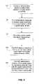
- FIG. 5summarizes an exemplary method that may be used to calculate a directional FLC value that is specific to wireless signals from a particular base station antenna that propagate toward a receiving area.
- directional FLC valuesare calculated at various measurement points in the receiving area by comparing location estimates obtained by using one or more terrestrial signals (e.g., using AFLT or hybrid methods) with location estimates obtained by more accurate methods (e.g., using GPS).
- the processmay begin when a mobile station, while at a measurement point in a receiving area (e.g., in a particular cell or sector) measures signals from GPS satellites and also measures at least one terrestrial signal, as indicated by block 200 .
- the measurement of at least one terrestrial signalcould be, for example, a measurement of the phase of a pilot signal from a CDMA base station.
- the mobile stationsends the signal measurement to the PDE, and the PDE uses the signal measurements to estimate the mobile station's location at the measurement point in at least two different ways.
- the PDEmay use just the GPS measurements to obtain a GPS-based location estimate, as indicated by block 202 .
- the PDEmay also use the at least one terrestrial signal measurement to obtain a terrestrial-based location estimate, as indicated by block 204 .
- the PDEmay obtain the terrestrial-based location estimate by using only terrestrial signal measurements (e.g., applying an AFLT positioning algorithm).
- the PDEmay combine the at least terrestrial signal measurement with one or more of the GPS measurements to obtain the terrestrial-based location estimate (e.g., applying a hybrid positioning algorithm).
- the GPS-based location estimatemay be used to calculate a directional FLC value that corrects the at least one terrestrial signal measurement, as indicated by block 206 .
- the directional FLC valuemay be calculated as a value that corrects the at least one terrestrial signal measurement so as to bring the location estimates calculated by the two different methods into agreement.
- the directional FLC value calculated in this waymay correct for the transmitting base station's time offset and may also correct for a location difference between an actual location of the base station's antenna and the base station location listed in the BSA.
- the process summarized in blocks 200 - 206may be repeated for mobile stations located at other measurement points in the receiving area. In this way, location estimates may be obtained for additional points in the receiving area to calculate additional directional FLC values for the at least one terrestrial signal, as indicated by block 208 .
- the directional FLC values that are calculated for different points in the receiving areamay differ because different points in the receiving area will receive the at least one terrestrial signal from somewhat different directions. However, for the purpose of simplicity, it may be desirable to have one directional FLC value for the entire receiving area. Thus, the directional FLC values calculated at different points in the receiving area may be averaged together to obtain a “best” directional FLC value for the receiving area, as indicated by block 210 .
- the “best” directional FLC valuemay be stored in the BSA, as indicated by block 212 .
- the directional FLC value stored in the BSAmay be used to correct subsequent measurements of the at least one terrestrial signal, when measured at any point in the receiving area.
- the method of FIG. 5may be used to obtain directional FLC values for a BSA that previously contained only non-directional FLC values.
- the method of FIG. 5may also be performed periodically in order to check or update existing directional FLC values.
- the corresponding directional FLC values stored in the BSAmay be updated automatically to reflect the change.
Landscapes
- Physics & Mathematics (AREA)
- Engineering & Computer Science (AREA)
- General Physics & Mathematics (AREA)
- Radar, Positioning & Navigation (AREA)
- Remote Sensing (AREA)
- Position Fixing By Use Of Radio Waves (AREA)
- Mobile Radio Communication Systems (AREA)
Abstract
Description
di=c(φi+bi−b0) (1)
Thus, the four phase measurements may be used to calculate the location of
[(x0−x1)2+(y0−y1)2]1/2=c(φ1+bi−b0) (2)
[(x0−x2)2+(y0−y2)2]1/2=c(φ2+b2−b0) (3)
[(x0−x3)2+(y0−y3)2]1/2=c(φ3+b3−b0) (4)
[(x0−x4)2+(y0−y4)2]1/2=c(φ4+b4−b0) (5)
bi′=bi+(di−di″)/c≈bi+(Δ cos θ)/c (6)
Each directional FLC value has a non-directional component, bi, that corrects for a base station time offset and a directional component, (di−di′)/c, that corrects for Δ, the base station's location offset. The directional FLC values may be stored in
[(x0−x1)2+(y0−y1)2]1/2=c(φ1+b1′−b0) (7)
[(x0−x2)2+(y0−y2)2]1/2=c(φ2+b2′−b0) (8)
[(x0−x3)2+(y0−y3)2]1/2=c(φ3+b3′−b0) (9)
[(x0−x4)2+(y0−y4)2]1/2=c(φ4+b4′−b0) (10)
Claims (12)
Priority Applications (3)
| Application Number | Priority Date | Filing Date | Title |
|---|---|---|---|
| US11/451,714US7659850B1 (en) | 2006-06-13 | 2006-06-13 | Method and system for determining locations of mobile stations using directional corrections |
| US12/533,471US7868826B1 (en) | 2006-06-13 | 2009-07-31 | Method and system for determining locations of mobile stations using directional corrections |
| US12/533,192US7800540B1 (en) | 2006-06-13 | 2009-07-31 | Method and system for determining locations of mobile stations using directional corrections |
Applications Claiming Priority (1)
| Application Number | Priority Date | Filing Date | Title |
|---|---|---|---|
| US11/451,714US7659850B1 (en) | 2006-06-13 | 2006-06-13 | Method and system for determining locations of mobile stations using directional corrections |
Related Child Applications (2)
| Application Number | Title | Priority Date | Filing Date |
|---|---|---|---|
| US12/533,471DivisionUS7868826B1 (en) | 2006-06-13 | 2009-07-31 | Method and system for determining locations of mobile stations using directional corrections |
| US12/533,192DivisionUS7800540B1 (en) | 2006-06-13 | 2009-07-31 | Method and system for determining locations of mobile stations using directional corrections |
Publications (1)
| Publication Number | Publication Date |
|---|---|
| US7659850B1true US7659850B1 (en) | 2010-02-09 |
Family
ID=41646451
Family Applications (3)
| Application Number | Title | Priority Date | Filing Date |
|---|---|---|---|
| US11/451,714Active2027-02-09US7659850B1 (en) | 2006-06-13 | 2006-06-13 | Method and system for determining locations of mobile stations using directional corrections |
| US12/533,192ActiveUS7800540B1 (en) | 2006-06-13 | 2009-07-31 | Method and system for determining locations of mobile stations using directional corrections |
| US12/533,471ActiveUS7868826B1 (en) | 2006-06-13 | 2009-07-31 | Method and system for determining locations of mobile stations using directional corrections |
Family Applications After (2)
| Application Number | Title | Priority Date | Filing Date |
|---|---|---|---|
| US12/533,192ActiveUS7800540B1 (en) | 2006-06-13 | 2009-07-31 | Method and system for determining locations of mobile stations using directional corrections |
| US12/533,471ActiveUS7868826B1 (en) | 2006-06-13 | 2009-07-31 | Method and system for determining locations of mobile stations using directional corrections |
Country Status (1)
| Country | Link |
|---|---|
| US (3) | US7659850B1 (en) |
Cited By (11)
| Publication number | Priority date | Publication date | Assignee | Title |
|---|---|---|---|---|
| US20090287415A1 (en)* | 2008-05-15 | 2009-11-19 | Helio, Llc | Systems, devices and methods for increasing location based service accuracy |
| US7800540B1 (en) | 2006-06-13 | 2010-09-21 | Sprint Spectrum L.P. | Method and system for determining locations of mobile stations using directional corrections |
| US20100238070A1 (en)* | 2009-03-18 | 2010-09-23 | Andrew Llc | System and method for concurrently determining locations of mobile device in wireless communication network |
| US20100240389A1 (en)* | 2009-03-18 | 2010-09-23 | Andrew Llc | System and method for locating mobile device in wireless communication network |
| CN102946004A (en)* | 2012-11-27 | 2013-02-27 | 长沙威佳通信科技有限公司 | Antenna adjusting method and device |
| US20140225779A1 (en)* | 2011-04-18 | 2014-08-14 | Instituto Presbiteriano Mackenzie | Process and system to determine temporal changes in retransmission and propagation of signals used to measure distances, syncronize actuators and georeference applications |
| WO2014124106A1 (en)* | 2013-02-07 | 2014-08-14 | Qualcomm Incorporated | Terrestrial positioning system calibration |
| US9178593B1 (en)* | 2009-04-21 | 2015-11-03 | Marvell International Ltd. | Directional channel measurement and interference avoidance |
| US9549288B2 (en) | 2013-02-07 | 2017-01-17 | Qualcomm Incorporated | Determination of differential forward link calibration in LTE networks for positioning |
| US20170280288A1 (en)* | 2016-03-24 | 2017-09-28 | Qualcomm Incorporated | Determining a time calibration value for a user equipment |
| US11102747B2 (en)* | 2016-09-23 | 2021-08-24 | Murata Manufacturing Co., Ltd. | Location estimation system and location estimation method |
Families Citing this family (1)
| Publication number | Priority date | Publication date | Assignee | Title |
|---|---|---|---|---|
| US9699611B1 (en) | 2016-01-04 | 2017-07-04 | Qualcomm Incorporated | Relative forward link calibration estimation |
Citations (17)
| Publication number | Priority date | Publication date | Assignee | Title |
|---|---|---|---|---|
| US5389934A (en)* | 1993-06-21 | 1995-02-14 | The Business Edge Group, Inc. | Portable locating system |
| US5485163A (en)* | 1994-03-30 | 1996-01-16 | Motorola, Inc. | Personal locator system |
| US20020009974A1 (en)* | 2000-07-17 | 2002-01-24 | Mikio Kuwahara | Wireless communication base station transmission timing offset correction system |
| US20030125044A1 (en) | 2001-12-27 | 2003-07-03 | Deloach James D. | Automation of maintenance and improvement of location service parameters in a data base of a wireless mobile communication system |
| US20030125045A1 (en)* | 2001-12-27 | 2003-07-03 | Riley Wyatt Thomas | Creating and using base station almanac information in a wireless communication system having a position location capability |
| US20030125046A1 (en)* | 2001-12-27 | 2003-07-03 | Wyatt Riley | Use of mobile stations for determination of base station location parameters in a wireless mobile communication system |
| US6609012B1 (en)* | 1998-08-24 | 2003-08-19 | Telefonaktiebolaget Lm Ericsson | Mobile terminal initiated and assisted antenna selection |
| US20030181163A1 (en)* | 2002-02-06 | 2003-09-25 | Ntt Docomo, Inc. | Radio resources allocating method, radio resources allocating apparatus, and mobile communication system |
| US20040091026A1 (en)* | 2002-10-31 | 2004-05-13 | Takashi Nakayama | Circuit for detecting a shifted frequency, a method for detecting a shifted frequency and portable communication apparatus |
| US20040203380A1 (en) | 2000-07-03 | 2004-10-14 | Maher Hamdi | Method and wireless terminal for generating and maintaining a relative positioning system |
| US20050020309A1 (en) | 2003-07-21 | 2005-01-27 | Mark Moeglein | Method and apparatus for creating and using a base station almanac for position determination |
| US20050227689A1 (en)* | 2004-04-13 | 2005-10-13 | Jewett David T | Method and apparatus for automatic calibration of positioning system base stations |
| US20060009235A1 (en) | 2004-06-18 | 2006-01-12 | Leonid Sheynblat | Method and apparatus for determining location of a base station using a plurality of mobile stations in a wireless mobile network |
| US20060052115A1 (en)* | 2004-09-07 | 2006-03-09 | Sanjeev Khushu | Procedure to increase position location availabilty |
| US20060063537A1 (en)* | 2004-09-20 | 2006-03-23 | Lee Young-Sik | Method and apparatus for determining position of mobile communication terminal |
| US20070216540A1 (en)* | 2003-07-23 | 2007-09-20 | Riley Wyatt T | Selecting a Navigation Solution Used in Determining the Position of a Device in a Wireless Communication System |
| US20070275717A1 (en)* | 2006-03-07 | 2007-11-29 | Qualcomm, Incorporated | Network selection by wireless terminals |
Family Cites Families (2)
| Publication number | Priority date | Publication date | Assignee | Title |
|---|---|---|---|---|
| US8160604B2 (en)* | 2002-04-18 | 2012-04-17 | Qualcomm Incorporated | Integrity monitoring in a position location system utilizing knowledge of local topography |
| US7659850B1 (en) | 2006-06-13 | 2010-02-09 | Sprint Spectrum L.P. | Method and system for determining locations of mobile stations using directional corrections |
- 2006
- 2006-06-13USUS11/451,714patent/US7659850B1/enactiveActive
- 2009
- 2009-07-31USUS12/533,192patent/US7800540B1/enactiveActive
- 2009-07-31USUS12/533,471patent/US7868826B1/enactiveActive
Patent Citations (17)
| Publication number | Priority date | Publication date | Assignee | Title |
|---|---|---|---|---|
| US5389934A (en)* | 1993-06-21 | 1995-02-14 | The Business Edge Group, Inc. | Portable locating system |
| US5485163A (en)* | 1994-03-30 | 1996-01-16 | Motorola, Inc. | Personal locator system |
| US6609012B1 (en)* | 1998-08-24 | 2003-08-19 | Telefonaktiebolaget Lm Ericsson | Mobile terminal initiated and assisted antenna selection |
| US20040203380A1 (en) | 2000-07-03 | 2004-10-14 | Maher Hamdi | Method and wireless terminal for generating and maintaining a relative positioning system |
| US20020009974A1 (en)* | 2000-07-17 | 2002-01-24 | Mikio Kuwahara | Wireless communication base station transmission timing offset correction system |
| US20030125044A1 (en) | 2001-12-27 | 2003-07-03 | Deloach James D. | Automation of maintenance and improvement of location service parameters in a data base of a wireless mobile communication system |
| US20030125045A1 (en)* | 2001-12-27 | 2003-07-03 | Riley Wyatt Thomas | Creating and using base station almanac information in a wireless communication system having a position location capability |
| US20030125046A1 (en)* | 2001-12-27 | 2003-07-03 | Wyatt Riley | Use of mobile stations for determination of base station location parameters in a wireless mobile communication system |
| US20030181163A1 (en)* | 2002-02-06 | 2003-09-25 | Ntt Docomo, Inc. | Radio resources allocating method, radio resources allocating apparatus, and mobile communication system |
| US20040091026A1 (en)* | 2002-10-31 | 2004-05-13 | Takashi Nakayama | Circuit for detecting a shifted frequency, a method for detecting a shifted frequency and portable communication apparatus |
| US20050020309A1 (en) | 2003-07-21 | 2005-01-27 | Mark Moeglein | Method and apparatus for creating and using a base station almanac for position determination |
| US20070216540A1 (en)* | 2003-07-23 | 2007-09-20 | Riley Wyatt T | Selecting a Navigation Solution Used in Determining the Position of a Device in a Wireless Communication System |
| US20050227689A1 (en)* | 2004-04-13 | 2005-10-13 | Jewett David T | Method and apparatus for automatic calibration of positioning system base stations |
| US20060009235A1 (en) | 2004-06-18 | 2006-01-12 | Leonid Sheynblat | Method and apparatus for determining location of a base station using a plurality of mobile stations in a wireless mobile network |
| US20060052115A1 (en)* | 2004-09-07 | 2006-03-09 | Sanjeev Khushu | Procedure to increase position location availabilty |
| US20060063537A1 (en)* | 2004-09-20 | 2006-03-23 | Lee Young-Sik | Method and apparatus for determining position of mobile communication terminal |
| US20070275717A1 (en)* | 2006-03-07 | 2007-11-29 | Qualcomm, Incorporated | Network selection by wireless terminals |
Cited By (24)
| Publication number | Priority date | Publication date | Assignee | Title |
|---|---|---|---|---|
| US7800540B1 (en) | 2006-06-13 | 2010-09-21 | Sprint Spectrum L.P. | Method and system for determining locations of mobile stations using directional corrections |
| US7868826B1 (en) | 2006-06-13 | 2011-01-11 | Sprint Spectrum L.P. | Method and system for determining locations of mobile stations using directional corrections |
| US20090287415A1 (en)* | 2008-05-15 | 2009-11-19 | Helio, Llc | Systems, devices and methods for increasing location based service accuracy |
| US20100238070A1 (en)* | 2009-03-18 | 2010-09-23 | Andrew Llc | System and method for concurrently determining locations of mobile device in wireless communication network |
| US20100240389A1 (en)* | 2009-03-18 | 2010-09-23 | Andrew Llc | System and method for locating mobile device in wireless communication network |
| US8160610B2 (en) | 2009-03-18 | 2012-04-17 | Andrew Llc | System and method for locating mobile device in wireless communication network |
| US9392521B2 (en) | 2009-03-18 | 2016-07-12 | Telecommunication Systems, Inc. | System and method for concurrently determining locations of mobile device in wireless communication network |
| US9178593B1 (en)* | 2009-04-21 | 2015-11-03 | Marvell International Ltd. | Directional channel measurement and interference avoidance |
| US9615374B1 (en) | 2009-04-21 | 2017-04-04 | Marvell International Ltd. | Directional channel measurement and interference avoidance |
| US20140225779A1 (en)* | 2011-04-18 | 2014-08-14 | Instituto Presbiteriano Mackenzie | Process and system to determine temporal changes in retransmission and propagation of signals used to measure distances, syncronize actuators and georeference applications |
| US9726759B2 (en)* | 2011-04-18 | 2017-08-08 | Instituto Presbiteriano Mackenzie | Process and system to determine temporal changes in retransmission and propagation of signals used to measure distances, syncronize actuators and georeference applications |
| CN102946004A (en)* | 2012-11-27 | 2013-02-27 | 长沙威佳通信科技有限公司 | Antenna adjusting method and device |
| US9237417B2 (en) | 2013-02-07 | 2016-01-12 | Qualcomm Incorporated | Terrestrial positioning system calibration |
| JP2016514247A (en)* | 2013-02-07 | 2016-05-19 | クゥアルコム・インコーポレイテッドQualcomm Incorporated | Ground positioning system calibration |
| CN104995526A (en)* | 2013-02-07 | 2015-10-21 | 高通股份有限公司 | Ground Positioning System Calibration |
| US9549288B2 (en) | 2013-02-07 | 2017-01-17 | Qualcomm Incorporated | Determination of differential forward link calibration in LTE networks for positioning |
| KR101715371B1 (en) | 2013-02-07 | 2017-03-10 | 퀄컴 인코포레이티드 | Terrestrial positioning system calibration |
| US9606215B2 (en) | 2013-02-07 | 2017-03-28 | Qualcomm Incorporated | Terrestrial positioning system calibration |
| KR20150115896A (en)* | 2013-02-07 | 2015-10-14 | 퀄컴 인코포레이티드 | Terrestrial positioning system calibration |
| JP2017083450A (en)* | 2013-02-07 | 2017-05-18 | クゥアルコム・インコーポレイテッドQualcomm Incorporated | Terrestrial positioning system calibration |
| WO2014124106A1 (en)* | 2013-02-07 | 2014-08-14 | Qualcomm Incorporated | Terrestrial positioning system calibration |
| US20170280288A1 (en)* | 2016-03-24 | 2017-09-28 | Qualcomm Incorporated | Determining a time calibration value for a user equipment |
| US10897686B2 (en)* | 2016-03-24 | 2021-01-19 | Qualcomm Incorporated | Determining a time calibration value for a user equipment |
| US11102747B2 (en)* | 2016-09-23 | 2021-08-24 | Murata Manufacturing Co., Ltd. | Location estimation system and location estimation method |
Also Published As
| Publication number | Publication date |
|---|---|
| US7868826B1 (en) | 2011-01-11 |
| US7800540B1 (en) | 2010-09-21 |
Similar Documents
| Publication | Publication Date | Title |
|---|---|---|
| US7659850B1 (en) | Method and system for determining locations of mobile stations using directional corrections | |
| US7822427B1 (en) | Method and system for using a wireless signal received via a repeater for location determination | |
| US7412248B2 (en) | System and method for location determination | |
| US7383049B2 (en) | Automation of maintenance and improvement of location service parameters in a data base of a wireless mobile communication system | |
| CA2471568C (en) | Use of mobile stations for determination of base station location parameters in a wireless mobile communication system | |
| US6728545B1 (en) | System and method for computing the location of a mobile terminal in a wireless communications network | |
| US6639554B2 (en) | Apparatus and method for tracking location of mobile station | |
| AU2009202647B2 (en) | Method and apparatus for determining location of a base station using a plurality of mobile stations in a wireless mobile network | |
| US8472971B2 (en) | Method and apparatus for determining whether a mobile terminal has moved outside a given locale | |
| JP4313202B2 (en) | Base station time calibration using positioning data sent from a mobile station during a regular location session | |
| EP2283683B1 (en) | Location services based on positioned wireless measurement reports | |
| CA2782805C (en) | Area based position determination for terminals in a wireless network | |
| US20030125045A1 (en) | Creating and using base station almanac information in a wireless communication system having a position location capability | |
| KR100986955B1 (en) | Generation and Use of Base Station Satellite Power Information in Wireless Communication System with Location Capability | |
| JP2000244968A (en) | Method for deciding position of mobile station in radio communication system | |
| JP2005509136A (en) | Mobile station location estimation method and apparatus | |
| WO2001089254A1 (en) | Method to calculate true round trip propagation delay and user equipment location in wcdma/utran | |
| CN101631349A (en) | Method, device and wireless operation maintenance center for positioning terminal | |
| US20090160710A1 (en) | Method and apparatus for estimating location to support location based service of terminal in mobile communication system | |
| US20060267840A1 (en) | Method and system of positioning | |
| KR101723229B1 (en) | Method for measuring position of a mobile terminal | |
| KR100574655B1 (en) | Subscriber location information service method of wireless communication network | |
| KR20240053387A (en) | Vehicle, and method for positioning of node | |
| Sineglazov et al. | Navigation systems based on global system for mobile communications |
Legal Events
| Date | Code | Title | Description |
|---|---|---|---|
| AS | Assignment | Owner name:SPRINT SPECTRUM L.P.,KANSAS Free format text:ASSIGNMENT OF ASSIGNORS INTEREST;ASSIGNORS:HOU, JIONGKUAN;SWIFT, JAMES C.;REEL/FRAME:017994/0107 Effective date:20060613 | |
| STCF | Information on status: patent grant | Free format text:PATENTED CASE | |
| FPAY | Fee payment | Year of fee payment:4 | |
| AS | Assignment | Owner name:DEUTSCHE BANK TRUST COMPANY AMERICAS, NEW YORK Free format text:GRANT OF FIRST PRIORITY AND JUNIOR PRIORITY SECURITY INTEREST IN PATENT RIGHTS;ASSIGNOR:SPRINT SPECTRUM L.P.;REEL/FRAME:041937/0632 Effective date:20170203 | |
| FPAY | Fee payment | Year of fee payment:8 | |
| AS | Assignment | Owner name:DEUTSCHE BANK TRUST COMPANY AMERICAS, NEW YORK Free format text:SECURITY AGREEMENT;ASSIGNORS:T-MOBILE USA, INC.;ISBV LLC;T-MOBILE CENTRAL LLC;AND OTHERS;REEL/FRAME:053182/0001 Effective date:20200401 | |
| AS | Assignment | Owner name:SPRINT SPECTRUM L.P., KANSAS Free format text:TERMINATION AND RELEASE OF FIRST PRIORITY AND JUNIOR PRIORITY SECURITY INTEREST IN PATENT RIGHTS;ASSIGNOR:DEUTSCHE BANK TRUST COMPANY AMERICAS;REEL/FRAME:052313/0299 Effective date:20200401 | |
| MAFP | Maintenance fee payment | Free format text:PAYMENT OF MAINTENANCE FEE, 12TH YEAR, LARGE ENTITY (ORIGINAL EVENT CODE: M1553); ENTITY STATUS OF PATENT OWNER: LARGE ENTITY Year of fee payment:12 | |
| AS | Assignment | Owner name:SPRINT SPECTRUM LLC, WASHINGTON Free format text:CHANGE OF NAME;ASSIGNOR:SPRINT SPECTRUM L.P.;REEL/FRAME:059044/0022 Effective date:20210325 | |
| AS | Assignment | Owner name:SPRINT SPECTRUM LLC, KANSAS Free format text:RELEASE BY SECURED PARTY;ASSIGNOR:DEUTSCHE BANK TRUST COMPANY AMERICAS;REEL/FRAME:062595/0001 Effective date:20220822 Owner name:SPRINT INTERNATIONAL INCORPORATED, KANSAS Free format text:RELEASE BY SECURED PARTY;ASSIGNOR:DEUTSCHE BANK TRUST COMPANY AMERICAS;REEL/FRAME:062595/0001 Effective date:20220822 Owner name:SPRINT COMMUNICATIONS COMPANY L.P., KANSAS Free format text:RELEASE BY SECURED PARTY;ASSIGNOR:DEUTSCHE BANK TRUST COMPANY AMERICAS;REEL/FRAME:062595/0001 Effective date:20220822 Owner name:SPRINTCOM LLC, KANSAS Free format text:RELEASE BY SECURED PARTY;ASSIGNOR:DEUTSCHE BANK TRUST COMPANY AMERICAS;REEL/FRAME:062595/0001 Effective date:20220822 Owner name:CLEARWIRE IP HOLDINGS LLC, KANSAS Free format text:RELEASE BY SECURED PARTY;ASSIGNOR:DEUTSCHE BANK TRUST COMPANY AMERICAS;REEL/FRAME:062595/0001 Effective date:20220822 Owner name:CLEARWIRE COMMUNICATIONS LLC, KANSAS Free format text:RELEASE BY SECURED PARTY;ASSIGNOR:DEUTSCHE BANK TRUST COMPANY AMERICAS;REEL/FRAME:062595/0001 Effective date:20220822 Owner name:BOOST WORLDWIDE, LLC, KANSAS Free format text:RELEASE BY SECURED PARTY;ASSIGNOR:DEUTSCHE BANK TRUST COMPANY AMERICAS;REEL/FRAME:062595/0001 Effective date:20220822 Owner name:ASSURANCE WIRELESS USA, L.P., KANSAS Free format text:RELEASE BY SECURED PARTY;ASSIGNOR:DEUTSCHE BANK TRUST COMPANY AMERICAS;REEL/FRAME:062595/0001 Effective date:20220822 Owner name:T-MOBILE USA, INC., WASHINGTON Free format text:RELEASE BY SECURED PARTY;ASSIGNOR:DEUTSCHE BANK TRUST COMPANY AMERICAS;REEL/FRAME:062595/0001 Effective date:20220822 Owner name:T-MOBILE CENTRAL LLC, WASHINGTON Free format text:RELEASE BY SECURED PARTY;ASSIGNOR:DEUTSCHE BANK TRUST COMPANY AMERICAS;REEL/FRAME:062595/0001 Effective date:20220822 Owner name:PUSHSPRING, LLC, WASHINGTON Free format text:RELEASE BY SECURED PARTY;ASSIGNOR:DEUTSCHE BANK TRUST COMPANY AMERICAS;REEL/FRAME:062595/0001 Effective date:20220822 Owner name:LAYER3 TV, LLC, WASHINGTON Free format text:RELEASE BY SECURED PARTY;ASSIGNOR:DEUTSCHE BANK TRUST COMPANY AMERICAS;REEL/FRAME:062595/0001 Effective date:20220822 Owner name:IBSV LLC, WASHINGTON Free format text:RELEASE BY SECURED PARTY;ASSIGNOR:DEUTSCHE BANK TRUST COMPANY AMERICAS;REEL/FRAME:062595/0001 Effective date:20220822 |