US7659833B2 - System and method for remotely controlling devices - Google Patents
System and method for remotely controlling devicesDownload PDFInfo
- Publication number
- US7659833B2 US7659833B2US11/195,040US19504005AUS7659833B2US 7659833 B2US7659833 B2US 7659833B2US 19504005 AUS19504005 AUS 19504005AUS 7659833 B2US7659833 B2US 7659833B2
- Authority
- US
- United States
- Prior art keywords
- signal
- binary
- module
- activation
- processor
- Prior art date
- Legal status (The legal status is an assumption and is not a legal conclusion. Google has not performed a legal analysis and makes no representation as to the accuracy of the status listed.)
- Expired - Fee Related, expires
Links
- 238000000034methodMethods0.000titleclaimsabstractdescription84
- 230000004044responseEffects0.000claimsabstractdescription48
- 238000006073displacement reactionMethods0.000claimsabstractdescription16
- 230000004913activationEffects0.000claimsdescription21
- 238000004140cleaningMethods0.000claimsdescription7
- 238000012544monitoring processMethods0.000claimsdescription6
- 230000003444anaesthetic effectEffects0.000claimsdescription5
- 238000005259measurementMethods0.000claimsdescription5
- 238000005299abrasionMethods0.000claimsdescription4
- 238000003384imaging methodMethods0.000claimsdescription4
- 238000005498polishingMethods0.000claimsdescription4
- 238000011321prophylaxisMethods0.000claimsdescription4
- 239000000523sampleSubstances0.000claimsdescription4
- 238000001356surgical procedureMethods0.000claimsdescription4
- 230000003213activating effectEffects0.000claimsdescription2
- 238000012549trainingMethods0.000description60
- 230000005540biological transmissionEffects0.000description43
- 230000001939inductive effectEffects0.000description16
- 239000003990capacitorSubstances0.000description7
- 101100521334Mus musculus Prom1 geneProteins0.000description3
- 238000004891communicationMethods0.000description3
- 238000005516engineering processMethods0.000description3
- 239000012530fluidSubstances0.000description3
- 230000003287optical effectEffects0.000description3
- 102100026816DNA-dependent metalloprotease SPRTNHuman genes0.000description2
- 101710175461DNA-dependent metalloprotease SPRTNProteins0.000description2
- 241000364021TulsaSpecies0.000description2
- 238000011282treatmentMethods0.000description2
- 210000000988bone and boneAnatomy0.000description1
- 150000001875compoundsChemical class0.000description1
- 125000004122cyclic groupChemical group0.000description1
- 230000000694effectsEffects0.000description1
- 230000007595memory recallEffects0.000description1
- 238000012986modificationMethods0.000description1
- 230000004048modificationEffects0.000description1
- 238000012545processingMethods0.000description1
- 238000011160researchMethods0.000description1
- 210000001519tissueAnatomy0.000description1
Images


Classifications
- A—HUMAN NECESSITIES
- A61—MEDICAL OR VETERINARY SCIENCE; HYGIENE
- A61C—DENTISTRY; APPARATUS OR METHODS FOR ORAL OR DENTAL HYGIENE
- A61C17/00—Devices for cleaning, polishing, rinsing or drying teeth, teeth cavities or prostheses; Saliva removers; Dental appliances for receiving spittle
- A61C17/16—Power-driven cleaning or polishing devices
- A61C17/20—Power-driven cleaning or polishing devices using ultrasonics
- A—HUMAN NECESSITIES
- A61—MEDICAL OR VETERINARY SCIENCE; HYGIENE
- A61C—DENTISTRY; APPARATUS OR METHODS FOR ORAL OR DENTAL HYGIENE
- A61C1/00—Dental machines for boring or cutting ; General features of dental machines or apparatus, e.g. hand-piece design
- A61C1/0007—Control devices or systems
- A61C1/0015—Electrical systems
- A61C1/0023—Foot control
Definitions
- This applicationrelates to a system and a method for remotely controlling devices.
- U.S. Pat. No. 4,156,187discloses a remote control system for controlling devices.
- the systemutilizes a first foot-actuated transmitter that transmits signals having one of three frequencies at a time that is received by a receiver for controlling one of three devices.
- a disadvantage with this systemis that when a second foot-actuated transmitter in another room transmits a signal having one of the three frequencies, the second foot-actuated transmitter could interfere with operation of the device. Further, the second foot-actuated transmitter could inadvertently control operation of the device when no operator is present in the room having the device.
- the inventors hereinhave recognized a need for a system for controlling devices using first, second, and third wireless radio-frequency (RF) modules, where the third wireless RF module only responds to an RF signal having first and second identifiers associated with the first and second modules, respectively, for controlling the devices.
- RFradio-frequency
- a system for remotely controlling at least a first device based on operation of a foot pedal apparatus in accordance with an exemplary embodimentis provided.
- the foot pedal apparatushas a movable member.
- the systemincludes a first module configured to transmit a first RF signal in response to at least partial displacement of the moveable member of the foot pedal apparatus from a first operational position.
- the first signalhas a first identifier.
- the systemfurther includes a second module configured to receive the first RF signal and to transmit a second RF signal having the first identifier and a second identifier in response to the first RF signal.
- the systemfurther includes a third module configured to receive the second RF signal and to control operation of the first device in response to the second RF signal.
- a method for remotely controlling at least a first device based on operation of a foot pedal apparatus having a movable member in accordance with another exemplary embodimentincludes transmitting a first RF signal from a first module in response to at least partial displacement of the moveable member of the foot pedal apparatus from a first operational position.
- the first signalhas a first identifier.
- the methodfurther includes transmitting a second RF signal from a second module having the first identifier and a second identifier in response to the first RF signal.
- the methodfurther includes controlling operation of the first device in response to the second RF signal.
- FIG. 1is a schematic of a system for remotely controlling devices including a foot pedal control system having a foot pedal apparatus, a device selection module, and a device control module;
- FIG. 2is a detailed schematic of the foot pedal control system and the foot pedal monitoring module of FIG. 1 ;
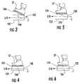
- FIGS. 3 and 4are schematics of an alternate foot pedal apparatus that can be utilized with the foot pedal control system of FIG. 1 ;
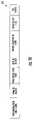
- FIGS. 5 and 6are schematics of another alternate foot pedal apparatus that can be utilized with a foot pedal control system of FIG. 1 ;
- FIG. 7is a schematic of the device selection module utilized in the system of FIG. 1 ;
- FIG. 8is a schematic of the device control module utilized in the system of FIG. 1 ;
- FIG. 9is a schematic of a transmission packet in an RF signal generated by the foot pedal monitoring module of FIG. 2 ;
- FIG. 10is a schematic of a transmission packet in an RF signal generated by the device selection module of FIG. 7 ;
- FIGS. 11-13are flowcharts of a method for training the device control module of FIG. 8 for controlling a first device
- FIGS. 14-16are flowcharts of a method for training the device control module of FIG. 8 for controlling a second device
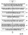
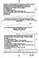
- FIGS. 17-20are flowcharts of a method for controlling the first device utilizing the system of FIG. 1 ;
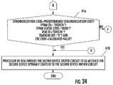
- FIGS. 21-24are flowcharts of the method for controlling the second device utilizing the system of FIG. 1 .
- FIG. 1a system 10 for remotely controlling devices 18 and 20 is illustrated. It should be noted that in an alternate embodiment, more than two devices can be controlled by the system 10 .
- the system 10includes a foot pedal control system 12 , a device selection module (DSM) 14 , and a device control module (DCM) 16 .
- DSMdevice selection module
- DCMdevice control module
- the foot pedal control system 12is provided to monitor an operational position of a moveable member 61 of the foot pedal apparatus 62 and to transmit RF signals in response to displacement of a movable member 61 from a first operational position.
- the foot pedal control system 12includes the foot pedal apparatus 40 , a foot pedal monitoring module (FPMM) 42 , an air pump 44 , a pneumatic switch 46 or pressure sensor 46 ′, a pneumatically controlled dental implement 48 , a valve 50 , and conduits 52 , 54 , 56 .
- FPMMfoot pedal monitoring module
- the foot pedal apparatus 40is provided to allow a user to displace the movable member 61 for controlling devices.
- the foot pedal apparatus 40includes a housing 60 , the movable member 61 , and a pneumatic valve 62 .
- the foot pedal apparatus 40is connected to an air pump 44 via the conduit 52 .
- the air pump 44supplies pressurized air at a predetermined pressure through conduit 52 to the pneumatic valve 62 in the foot pedal apparatus 40 .
- the pneumatic valve 62is further operatively coupled to the conduit 54 .
- the conduit 54extends from the pneumatic valve 62 to the pneumatic valve 50 .
- the valve 50is further coupled to a pneumatically controlled dental implement 48 .
- a pneumatic switch 46 or a pressure sensor 46 ′is operatively coupled to the conduit 54 .
- the switch 46 or pressure sensor 46 ′transmits a signal to I/O interface 76 that is received by the processor 70 .
- the pneumatic valve 62opens to propagate pressurized air from air pump 44 to the pneumatic valve 50 for driving dental implement 48 .
- the valve 50only opens when a user removes dental implement 48 from a holding fixture (not shown).
- the inventors hereinhave recognized that foot pedal apparatus 40 can be further utilized to remotely control a plurality of other devices.
- the pneumatic switch 46detects an air pressure level greater than or equal to a threshold pressure level and generates a signal that is received by the I/O interface 76 .
- the processor 70In response to the signal from the switch 46 , the processor 70 generates a control signal to induce the RF transmitter 78 to generate one or more RF signals as will be explained in greater detail below.
- the pressure sensor 46 ′when the pressure sensor 46 ′ is utilized instead of the pneumatic switch 46 , the pressure sensor 46 ′ generates a pressure signal indicative of the pressure in the conduit 54 .
- the processor 70When the pressure signal indicates an air pressure level greater than or equal to the threshold pressure level, the processor 70 generates a control signal to induce the RF transmitter 78 to generate one or more RF signals. It should be noted that the air pressure level in the conduit 54 is greater than or equal to the threshold pressure level when the movable member 61 at least partially opens the valve 62 .
- the foot pedal apparatus 40can be replaced with a foot pedal apparatus 100 .
- the foot pedal apparatus 100includes a housing 102 , a movable member 104 , and an electrical switch 106 .
- the movable member 104is operably coupled to the electrical switch 106 .
- the switch 106is moved from an open operational position to a closed operational position, respectively.
- a port on the I/O interface 76detects a ground voltage signal on the respective port that is received by the processor 70 .
- the processor 70is configured to generate a control signal for inducing the RF transmitter 78 to transmit one or more RF signals.
- the foot pedal apparatus 40can be replaced with a foot pedal apparatus 120 .
- the foot pedal apparatus 120includes a housing 122 , a movable member 124 , and an electrical switch 126 .
- the movable member 124is operably coupled to the electrical switch 126 .
- the switch 126is moved from an open operational position to a closed operational position, respectively.
- a port on the I/O interface 76to detects a ground voltage signal on the respective port that is received by the processor 70 .
- the processor 70is configured to generate a control signal for inducing the RF transmitter 78 to transmit one or more RF signals.
- the foot pedal apparatus 40can be replaced with a foot pedal apparatus having a moveable member operably coupled to a potentiometer.
- the potentiometerwould output a voltage signal having an amplitude proportional to an amount of displacement of the moveable member from a first operational position.
- the voltage signalwould be received by the I/O interface 76 .
- the foot pedal monitoring module (FPMM) 42is provided to monitor an operational position of the movable member 61 of the foot pedal apparatus 40 . Further, the FPMM 42 is provided to transmit one or more RF signals when the user displaces the movable member 61 from a first operational position. For example, the module 42 can transmit the RF signal when the user displaces the movable member 61 from the first operational position (shown in FIG. 2 ) to a second operational position (shown in FIG. 1 ).
- An advantage of FPMM 42is that all of the communication between FPMM 42 and the other modules in system 10 devices are “wireless” communications thus eliminating a plurality of communication wires from the FPMM 42 to the plurality of devices being controlled.
- the FPMM 42includes a processor 70 , a read-only memory (ROM) 72 , a random access memory (RAM) 74 , an EEPROM 75 , an input/output (I/O) interface 76 , the RF transmitter 78 , an antenna coil 80 , a capacitor 82 , an LED 84 , the pneumatic switch 46 or the pressure sensor 46 ′.
- ROMread-only memory
- RAMrandom access memory
- I/Oinput/output
- the processor 70is provided to monitor signals from either the pneumatic switch 46 or the pressure sensor 46 ′ to determine when to generate control signals for inducing the RF transmitter 78 to generate one or more RF signals. Further, the processor 70 is configured to generate a control signal that is transmitted through the I/O interface 76 to the LED 84 for inducing the LED 84 to a emit light when the RF transmitter 78 is transmitting an RF signal.
- the processor 70is operably coupled to the I/O interface 76 , the RF transmitter 78 , and to computer readable media including the ROM 72 , the RAM 74 , the EEPROM 75 .
- the computer readable media utilized by the processor 70may be implemented using any of a number of known memory devices such as PROMs, EPROMs, EEPROMs, flash memory or any other electric, magnetic, optical or combination memory device capable of storing information, some of which represent executable instructions.
- the ROM 72 and the RAM 74are provided to store software algorithms and associated information utilized by the processor 70 .
- the EEPROM 75stores a unique FPMM identifier associated with the FPMM 12 .
- the processor 70comprises any device that is capable of performing an arithmetic or logical operation.
- the processor 70can comprise a microprocessor or a field programmable gate array, or the like.
- the processor 70is operably coupled to a battery (not shown) or other external power source for supplying an operational voltage to the processor 70 .
- the RF transmitter 78is provided to transmit RF signals via antenna coil 80 in response to control signals received from the processor 70 .
- the RF transmitter 78is operably coupled to a series combination of the capacitor 82 and the antenna coil 80 .
- the RF transmitter 78transmits RF signals an low frequency (LF) frequency range (e.g., 30 Khz-300 Khz).
- LFlow frequency
- the RF transmitter 78can transmit RF signals in one or more other frequency ranges, including for example, (i) a very low frequency (VLF) range (e.g., 9 Khz-30 Khz), (ii) a medium frequency (MF) range (e.g., 300 Khz-3 Mhz), (iii) a high frequency (HF) range (e.g., 3 Mhz-30 Mhz), (iv) an ultra high frequency (UHF) range (e.g., 300 Mhz-3 Ghz), (v) a super high frequency (SHF) range (e.g., 3 Ghz-30 Ghz), and (vi) an extremely high frequency (EHF) range (e.g., 30 Ghz-300 Ghz).
- VLFvery low frequency
- MFmedium frequency
- HFhigh frequency
- UHFultra high frequency
- SHFsuper high frequency
- EHFextremely high frequency
- the RF transmitter 78can modulate each RF signal containing a transmission packet using a frequency shift keying (FSK) modulation technique.
- the RF transmitter 78can modulate each RF signal containing a transmission packet using any other known modulation technique, such as amplitude modulation (AM), frequency modulation (FM), and amplitude shift keying (ASK), or the like.
- the RF transmitter 78can transmit pulsed RF signals for predetermined time intervals, such as 15 milliseconds for example.
- the transmission packet 220includes: (i) a preamble code, (ii) a synchronization code, (iii) a FPMM identifier (ID), a FPMM status code, and a checksum.
- the preamble codeis utilized to wake-up and stabilize an RF receiver 139 on the DSM 14 .
- the preamble codecomprises a 4-bit value.
- the synchronization codeis utilized to allow an RF receiver to synchronize with the RF transmitter 78 for decoding a transmission packet in a received RF signal.
- the synchronization codecomprises a 10-bit value.
- the FPMM IDis utilized to identify a transmission packet associated with the FPMM 42 .
- the FPMM IDcomprises a 20-bit value.
- the FPMM status codeis utilized to indicate whether the movable member 61 is displaced from a first operational position. When the movable member 61 is displaced from the first operational position, the FPMM status code has a “0001” binary value (e.g., an activation command) indicating an “on” condition. Alternately, when the movable member 61 is not displaced from the first operational position, the FPMM status code has a “0000” binary value (e.g., a de-activation command) indicating an “off” condition.
- the FPMM status codecomprises a 4-bit value.
- the checksum valueis calculated based upon the FPMM ID, and the FPMM status code, using a checksum algorithm known to those skilled in the art. It should be noted that the processor 70 stores the transmission packet 220 in a computer readable medium prior to transmission of the transmission packet 220 in an RF signal.
- An advantage of the foot pedal control system 12is that the foot pedal apparatus 40 has a single movable member utilized to selectively control a plurality of devices. Thus, other foot pedal units having a plurality of movable members or pedals for controlling a plurality of devices are no longer needed. Thus, with the foot pedal control system 12 , dental or medical professionals will not have to “search” for the correct pedal from a plurality of pedals with their feet to actuate a desired device, as done with other foot pedal units having a plurality of foot pedals. Further, a plurality of other foot pedal units each having a pedal for controlling a distinct device will no longer be needed. Thus, because the foot pedal apparatus 40 can replace a plurality of other foot pedal units, a treatment room will have a less cluttered floor. Further, dental or medical professionals using the foot pedal apparatus 40 can obtain a consistent “feel” or depression force for controlling multiple devices.
- the DSM 14is provided to receive one or more RF signals from the FPMM 42 , and to transmit one or more RF signals each having a transmission packet to the DCM 16 , for controlling devices operably coupled to the DCM 16 .
- the DSM 14is further provided to allow a user to select one of a plurality of the switches that will be associated with a respective device operably coupled to the DCM 16 .
- the DSM 14includes a processor 130 , a ROM 132 , a RAM 134 , an EEPROM 135 , an I/O interface 136 , an RF receiver 138 , antenna coils 140 , 142 , 144 , capacitors 146 , 148 , 150 , an RF transmitter 152 , an antenna 154 , switches 156 , 158 , 160 , and LEDs 162 , 164 , 166 .
- the DSM 14can be utilized with a plurality of FPMMs.
- a usercan utilize the DSM 14 in multiple treatment rooms wherein each room has a separate FPMM, because the RF signals transmitted from DSM 14 contain both a FPMM ID from a FPMM in a specific room and a DSM ID associated with the DSM 14 .
- the DSMcan act as a master controller by only activating the DCM that is trained for an associated pair of IDs (i.e., a specific FPMM ID and DSM ID).
- the DSM 14has a training operational mode and a non-training operational mode.
- the module 14transmits an RF signal having a training transmission packet to the DCM 16 such that the DCM 16 can store a FPMM ID and a DSM ID associated with the FPMM 42 and the DSM 14 , respectively.
- the DCM 16will utilize the stored FPMM ID and the DSM ID to recognize transmission packets from the DSM 14 for controlling specific devices coupled to the DCM 16 .
- the module 14transmits an RF signal having control information for controlling operation of the DCM 16 and a device operably coupled to the DCM 16 .
- the processor 130is operably coupled to the I/O interface 136 , the RF transmitter 152 , the RF receiver 138 , and to the computer readable media including the ROM 132 , the RAM 134 , and the EEPROM 135 .
- the computer readable media utilized by the processor 130may be implemented using any of a number of known memory devices such as PROMs, EPROMs, EEPROMs, flash memory or any other electric, magnetic, optical or combination memory device capable of storing information, some of which represent executable instructions.
- the EEPROM 135stores a DSM ID associated with the DSM 14 .
- the processor 130monitors an operational state (e.g., a closed operational state or an open operational state) of the switches 156 , 158 , 160 utilizing the I/O interface 136 . Further, the processor 130 controls the LEDs 162 , 164 , 166 utilizing the I/O interface 136 .
- the processor 130is provided to decode transmission packets in RF signals received by the RF receiver 138 from the FPMM 42 . Further, the processor 130 is provided to generate transmission packets and control signals for inducing the RF transmitter 152 to transmit RF signals including transmission packets to the DCM 16 for controlling operation of the DCM 16 .
- the processor 130is configured to enter the training operational mode when the training mode switch 160 is moved to a closed operational position for transmitting RF signals having training information to the DCM 16 such that the DCM 16 can recognize subsequent RF signals from the DSM 14 . Further, the processor 130 is configured to enter a non-training operational mode when the training mode switch 160 is moved to an open operational position for transmitting RF signals having control information for controlling operation of the DCM 16 . Further, the processor 130 is configured to determine when the switch 156 is moved to a closed operational position for selecting a first device operably coupled to the DCM 16 . Further, the processor 130 is configured to determine when the switch 158 is moved to a closed operational position for selecting a second device operably coupled to the DCM 16 .
- the processor 130is configured to generate a control signal for inducing the LED 162 to emit light when RF signals are being received by the RF receiver 138 . Further, the processor 130 is configured to generate a control signal for inducing the LED 164 to emit light when an RF signal is being transmitted from the RF transmitter 152 . Further, the processor 130 is configured to generate a control signal for inducing the LED 166 to emit light when the processor 130 enters the training operational mode.
- the processor 130comprises any device that is capable of performing an arithmetic or logical operation. For example, the processor 130 can comprise a microprocessor or a field programmable gate array, or the like.
- the processor 130is operably coupled to a battery (not shown) or an external power supply for supplying an operational voltage to the processor 130 .
- the RF transmitter 152is provided to transmit RF signals via antenna coil 154 in response to control signals received from the processor 130 .
- the RF transmitter 152transmits RF signals in a medium frequency (MF) range (e.g., 300 Khz-3 Mhz).
- MFmedium frequency
- the RF transmitter 152can transmit RF signals in one or more other frequency ranges, including for example, (i) the VLF range (e.g., 9 Khz-30 Khz), (ii) the LF range (e.g., 30 Khz-300 Khz), (iii) the HF range (e.g., 3 Mhz-30 Mhz), (iv) the UHF range (e.g., 300 Mhz-3 Ghz), (v) the SHF range (e.g., 3 Ghz-30 Ghz), and (vi) the EHF range (e.g., 30 Ghz-300 Ghz).
- the VLF rangee.g., 9 Khz-30 Khz
- the LF rangee.g., 30 Khz-300 Khz
- the HF rangee.g., 3 Mhz-30 Mhz
- the UHF rangee.g., 300 Mhz-3 Ghz
- SHF rangee.g., 3 Ghz-30 Gh
- the RF transmitter 152can modulate each RF signal containing a transmission packet using a FSK modulation technique.
- the RF transmitter 152can modulate each RF signal containing a transmission packet using any other known modulation technique, such as AM, FM, or ASK, or the like.
- the RF transmitter 152can transmit pulsed RF signals for predetermined time intervals, such as 15 milliseconds for example.
- the RF receiver 138is provided to receive RF signals from the FPMM 42 .
- the RF receiver 138includes an RF receiver microchip 139 , antenna coils 140 , 142 , 144 , and capacitors 146 , 148 , 150 .
- the RF receiver microchip 139is electrically coupled at nodes 167 , 169 to a parallel combination of the capacitor 146 and the antenna coil 140 .
- the RF receiver microchip 139is electrically coupled at nodes 170 , 172 to a parallel combination of the capacitor 150 and the antenna 142 . Further, the RF receiver microchip 139 is electrically coupled at nodes 174 , 175 to a parallel combination of the capacitor 148 and the antenna coil 144 .
- the antenna coils 140 , 142 , 144are positioned for receiving RF signals along at least one of three axes.
- a long axis of the antenna coil 140is disposed substantially perpendicular to a long axis of the antenna coil 144 .
- a long axis of the antenna coil 144is disposed substantially perpendicular to a long axis of the antenna coil 142 .
- the transmission packet 222includes: (i) a synchronization code, (ii) an FPMM ID, (iii) a FPMM status code, (iv) a DSM ID, (v) a device selection ID, (vi) a training bit, and (vii) a CRC code.
- the synchronization codeis utilized to allow an RF receiver in the DCM 16 to synchronize with the RF transmitter 152 for decoding a transmission packet in a received RF signal.
- the synchronization codecomprises a 7-bit value.
- the FPMM IDis utilized to identify a transmission packet associated with the FPMM 42 .
- the FPMM IDcomprises a 20-bit value.
- the FPMM status codeis utilized to indicate whether the movable member 61 is displaced from a first operational position. When the movable member 61 of the foot pedal apparatus 40 is displaced from the first operational position, the FPMM status code has a “0001” binary value indicating an “on” condition. Alternately, when the movable member 61 is not displaced from the first operational position, the FPMM status code has a “0000” binary value indicating an “off” condition.
- the DSM IDis utilized to identify a transmission packet associated with the DSM 14 . In one embodiment, the DSM ID comprises a 20-bit value.
- the device selection IDis utilized to identify which device selection switch on the DSM 14 has been moved to a closed operational position, and also which device is to be controlled by the DCM 16 .
- the training bitis utilized to indicate whether the transmission packet is a training transmission packet or not. When the training bit has a “1” binary value indicating the transmission packet is a training transmission packet, the DCM 16 will associate a bi-directional switch therein and a device operably coupled to the bi-directional switch to the FPMM ID, the DSM ID, and the device selection ID.
- the DCM 16When the training bit has a “0” binary value indicating a transmission packet is not a training transmission packet, the DCM 16 will control the bi-directional switch and the device operably coupled to the bi-directional switch, that are associated with the received FPMM ID, the DSM ID, and the device selection ID.
- the cyclic redundancy code (CRC)is calculated based upon the FPMM ID, the FPMM status code, the DSM ID, the device selection ID, and the training bit, using an algorithm known to those skilled in the art.
- the processor 130stores the transmission packet 222 in a computer readable medium prior to transmission of the transmission packet 222 in an RF signal.
- the DCMis provided to receive one or more RF signals from the DSM 14 for controlling devices operably coupled to the DCM 16 .
- the DCM 16includes a processor 180 , a ROM 182 , a RAM 184 , an EEPROM 185 , an I/O interface 186 , an RF receiver circuit 188 , an antenna coil 190 , switches 192 , 194 , LEDs 196 , 198 , resistors 200 , 202 , 204 , 206 , and optically coupled bi-directional switches 208 , 212 .
- the processor 180is provided to control operation of the bi-directional switches 208 , 212 to control operation of the devices 18 , 20 respectively, based on RF signals received from the DSM 14 .
- the processor 180is operably coupled to the RF receiver circuit 188 , the I/O interface 186 and to the computer readable media including the ROM 182 , the RAM 184 , the EEPROM 185 .
- the computer readable media utilized by the processor 180may be implemented using any of a number of known memory devices such as PROMs, EPROMs, EEPROMs, flash memory or any other electric, magnetic, optical or combination memory device capable of storing information, some of which represent executable instructions.
- the processor 180is configured to monitor an operational state (e.g., a closed operational state or an open operational state) of the switches 192 , 194 utilizing the I/O interface 186 , and to control the LEDs 196 , 198 and the bi-directional switches 208 , 212 utilizing the I/O interface 186 . Further, the processor 180 is configured to decode transmission packets in RF signals received by the RF receiver circuit 188 from the DSM 14 .
- an operational statee.g., a closed operational state or an open operational state
- the processor 180is configured to decode transmission packets in RF signals received by the RF receiver circuit 188 from the DSM 14 .
- the processor 180has a training operational mode and a non-training operational mode.
- the processor 180is configured to enter the training operational mode when one of the training mode switches 192 , 194 is moved to a closed operational position.
- the training mode switch 192is moved to the closed operational position and the RF receiver circuit 188 subsequently receives a first RF signal having a first transmission packet with a training bit equal to “1” from the DSM 14
- the processor 180stores the FPMM ID, the DSM ID, and the device selection ID from the first transmission packet in the EEPROM 185 .
- the processor 180associates the stored values from the first transmission packet with the bi-directional switch 208 that is operably coupled to the device 18 .
- the processor 180stores the FPMM ID, the DSM ID, and the device selection ID from the second transmission packet in the EEPROM 185 . Further, the processor 180 associates these stored values from the second transmission packet with the bi-directional switch 208 that is operably coupled to the device 18 .
- the processor 180When the processor 180 decodes a transmission packet having a FPMM ID, a DSM ID, and a device selection ID associated with the bi-directional switch 208 , the processor 180 generates a control signal for inducing the bi-directional switch 208 to activate the device 18 . Further, the processor 180 generates a control signal for inducing the LED 196 to emit light. Alternately, when the processor 180 decodes a transmission packet having a FPMM ID, a DSM ID, and a device selection ID associated with the bi-directional switch 212 , the processor 180 generates a control signal for inducing the bi-directional switch 212 to activate the device 20 . Further, the processor 180 generates a control signal for inducing the LED 198 to emit light.
- the processor 180comprises any device that is capable of performing an arithmetic or logical operation.
- the processor 180can comprise a microprocessor or a field programmable gate array, or the like.
- the processor 180can be operably coupled to a battery (not shown) or another electric power source for supplying an operational voltage to the processor 180 .
- the optically coupled bi-directional switch 208is provided to control operation of the device 18 in response to a control signal from the processor 180 .
- the switch 208activates the device 18 in response to a control signal received from the processor 180 via the I/O interface 186 . Further, the switch 208 de-activates the device 18 when the switch 208 no longer receives the control signal from the processor 180 .
- the switch 208includes a light emitting element 209 and an optically responsive switching element 210 . As shown, the light-emitting element 209 is electrically coupled between a node 201 and electrical ground.
- a resistor 200is electrically coupled between the I/O interface 186 and the node 201
- a resistor 202is electrically coupled between the node 201 and electrical ground.
- the device 18is electrically coupled to the optically responsive switching element 210 .
- the bi-directional switch 208receives a control signal from the processor 180
- the light-emitting element 209emits light inducing the optically responsive switching element 210 to activate the device 18
- the bi-directional switch 208stops emitting light inducing the optically responsive switching element 210 to de-activate the device 18 .
- the optically coupled bi-directional switch 212is provided to control operation of the device 20 in response to a control signal from the processor 180 .
- the switch 212activates the device 20 in response to a control signal received from the processor 180 via the I/O interface 186 . Further, the switch 212 de-activates the device 20 when the switch 212 no longer receives the control signal from the processor 180 .
- the switch 212includes a light emitting element 213 and an optically responsive switching element 214 . As shown, the light-emitting element 213 is electrically coupled between a node 205 and electrical ground.
- a resistor 204is electrically coupled between the I/O interface 186 and the node 205
- a resistor 206is electrically coupled between the node 205 and electrical ground.
- the device 20is electrically coupled to the optically responsive switching element 214 .
- the bi-directional switch 212receives a control signal from the processor 180
- the light-emitting element 213emits light inducing the optically responsive switching element 214 to activate the device 20
- the bi-directional switch 212does not receive the control signal from the processor 180
- the light-emitting element 213stops emitting light inducing the optically responsive switching element 212 to de-activate the device 20 .
- the devices 18 , 20may comprise any electrically, pneumatically, magnetically, or hydraulically actuated device.
- devices 18 , 20may comprise electrically, pneumatically, magnetically, or hydraulically actuated medical or dental devices.
- devices 18 , 20may comprise one or more of the following devices: a drill, a dental chair whose chair position can be adjusted automatically, an infrared photo-optic imaging camera, a dental irrigator, an intra-oral camera, a laser, an air-abrasion unit, an electro-surgery unit, an ultrasonic teeth cleaning unit, a piezo-ultrasonic unit, an air polishing prophylaxis device, a gum depth measurement probe, a surgical microscope, a microprocessor controlled anesthetic delivery system, and an endodontic heat source device.
- one or more of the devices 18 , 20can comprise a torque control motor drill sold under the trademark Tecnika and is manufactured by Advanced Technology Research (ATR), located at Via del Pescino, 6, 51100 Pistoia, Italy, and sold in the United States by Dentsply Tulsa Dental at 5001 E. 68 th , Tulsa, Okla. 74136-3332.
- ATRAdvanced Technology Research
- the DCM 16could be used to control operation of any electrically controlled or pneumatically controlled drill.
- one or more of the devices 18 , 20can comprise a dental chair sold under the trademark Priority® manufactured by A-DEC located at 2601 Crestview Drive, Newberg, Oreg., which provides elevational control of the chair, tilting of the back of the chair, and memory recall positions.
- Priority®manufactured by A-DEC located at 2601 Crestview Drive, Newberg, Oreg.
- the elevation position, tilting position, and other variable position adjustmentscould be controlled by the inventive control system.
- the DCM 16could be used to control operation of any electrically controlled or hydraulically controlled dental chair or control unit associated with the dental chair.
- one or more of the devices 18 , 20can comprise an infrared photo-optic imaging camera sold under the trademark CEREC® manufactured by Sirona Dental Systems located at Fabrikstrabe 31, 64625 Bensheim, Hessen, Germany, and sold in the United States by Patterson Dental Supply, Inc., located at 1031 Mendota Heights Rd., Saint Paul, Minn. 55120.
- CEREC®infrared photo-optic imaging camera
- the DCM 16could be used to control any imaging camera that can be automatically or externally controlled to generate a digital image or a film image.
- one or more of the devices 18 , 20can comprise a dental irrigator sold under the trademark Piezon® Master 600, manufactured by Electro Medical Systems located at 12092 Forestgate Drive, Dallas Tex., 75243.
- the DCM 16could be used to control operation of any dental irrigator or dental irrigator control system that directs fluid under pressure therethrough.
- one or more of the devices 18 , 20can comprise an intra-oral camera sold under the trademark PrismTM, manufactured by Professional Dental Technologies, Inc., located at 2410 Harrison Street, Batesville, Ark. 72501, or the AcuCam® Concept IV manufactured by Gendex, a division of Dentsply International located at 901 W. Oakton St., Des Plains, Ill. 60018-1884.
- the DCM 16could be used to control operation of any intra-oral camera (or video capture card or video capture computer associated with the camera) to generate, store, retrieve, display, or print a digital or analog video image.
- one or more of the devices 18 , 20can comprise a laser sold under the trademark OdysseyTM, manufactured by Ivoclar Vivadent Inc., located at 175 Pineview Drive, Amherst, N.Y. 14228.
- the systemcould be utilized with a laser sold under the trademark Waterlase®, manufactured by Biolase Technology, Inc., located at 981 Calle Amanecer, San Clemente, Calif. 92673.
- the DCM 16could be used to control operation of any other known laser.
- one or more of the devices 18 , 20can comprise an air-abrasion unit sold under the trademark PrepStartTM, manufactured by Danville Engineering, located at 2021 Omega Road, San Ramon Calif. 94583.
- PrepStartTMmanufactured by Danville Engineering, located at 2021 Omega Road, San Ramon Calif. 94583.
- the DCM 16could be used to control operation of any other type of air-abrasion unit utilized in dental procedures, in medical procedures, or during processing or cleaning of manufactured goods.
- one or more of the devices 18 , 20can comprise an electro-surgery unit sold under the trademark Hyfrecator® 2000, manufactured by ConMed® Corporation, located at 310 Broad Street, Utica, N.Y. 13501.
- the DCM 16could be used to control operation of any other electro-surgery unit that utilizes electrical energy for removing tissue or bone.
- one or more of the devices 18 , 20can comprise the ultrasonic teeth cleaning unit sold under the trademark Cavitron® 3000 manufactured by Dentsply International located at 901 W. Oakton Street, Des Plains, Ill. 60018-1884. Further, it should be noted that the DCM 16 could be used to control operation of any other ultrasonic teeth cleaning unit.
- one or more of the devices 18 , 20can comprise a piezo-ultrasonic unit sold under the trademark Spartan MTSTM, manufactured by Obtura Spartan located at 1663 Fenton Business Park Court, Fenton, Mo. 63026.
- the DCM 16could be used to control operation of any other piezo-ultrasonic unit that agitates or vibrates a tip for cleaning teeth or removing tooth structure. Piezo-ultrasonic units may have fluid cooled tips.
- one or more of the devices 18 , 20can comprise an air polishing prophylaxis device sold under the trademark Cavitron® Prophy-Jet®, manufactured by Dentsply International located at 901 W. Oakton Street, Des Plains, Ill. 60018-1884.
- the DCM 16could be used to control operation of any other air polishing prophylaxis device that uses compressed air for delivering a fluid and/or an abrasive compound out of a nozzle for cleaning teeth and gums.
- one or more of the devices 18 , 20can comprise the gum depth measurement probe sold under the trademark Florida Probe®, manufactured by Florida Probe Corporation, located at 3700 NW 91 st Street, Suite C-100, Gainesville, Fla. 32606. Further, it should be noted that the DCM 16 could be used to control operation of any other gum depth measurement probe that can be automatically or externally controlled to take a gum depth measurement.
- one or more of the devices 18 , 20can comprise a surgical microscope sold under the trademark OPMI® pico, manufactured by Carl Zeiss Surgical Inc., located at One Ziess Drive, Thornwood, N.Y. 10594.
- the DCM 16could utilized with the surgical microscope sold under the trademark ProtégéTM, manufactured by Global Surgical Corporation, located at 3610 Tree Court Industrial Blvd., St. Louis, Mo. 63122-6622.
- the DCM 16could be used to control operation of any other surgical microscope that includes one or more of: automatically controllable height adjustment, automatically controllable focusing, automatically controllable field of view size, viewing lights, and a camera associated with the surgical microscope.
- one or more of the devices 18 , 20can comprise an anesthetic delivery system sold under the trademark The WandTM II, manufactured by the Dental Division of Milestone Scientific located at 151 S. Pfingsten Road, Deerfield, Ill. 60015.
- the DCM 16could be used to control operation of any other microprocessor-controlled anesthetic delivery system that delivers predetermined amounts of an anesthetic to a medical or dental patient.
- one or more of the devices 18 , 20can comprise an endodontic heat source device sold under the trademark System B HeatSourceTM model 1005, manufactured by Analytic-Sybron Dental Specialties located at 1332 South Lone Hill Avenue, Glendora, Calif. 91740. Further, it should be noted that the DCM 16 could be used to control operation of any other endodontic heat source device.
- System B HeatSourceTM model 1005manufactured by Analytic-Sybron Dental Specialties located at 1332 South Lone Hill Avenue, Glendora, Calif. 91740.
- the DCM 16could be used to control operation of any other endodontic heat source device.
- a usercloses a training mode switch 192 on the DCM 16 associated with an optically coupled bi-directional switch 208 therein to induce the DCM 16 to enter a training operational mode.
- step 232the processor 180 in the DCM 16 energizes an LED 196 in response to closure of the training mode switch 192 and resets and starts a first timer.
- step 234the user closes a training mode switch 160 on the DSM 14 to induce the DSM 14 to enter a training operational mode.
- step 236the processor 130 in the DSM 14 energizes a LED 166 in response to closure of the training mode switch 160 .
- step 238the user closes a device selection switch 156 on the DSM 14 to specify a first device selection ID having a “00001” binary value.
- the processor 130 in the DSM 14energizes an LED 162 in response to closure of the device selection switch 156 .
- the LED 162is associated with the device selection switch 156 . Further, the processor 130 resets and starts a second timer.
- step 242the user at least partially displaces a moveable member 61 of foot pedal apparatus 40 from a first operational position.
- the foot pedal apparatus 40is operably coupled to the FPMM 42 .
- each first RF signalis in the LF frequency range.
- each first RF signalincludes: (i) a preamble code, (ii) a synchronization code, (iii) an FPMM ID having a “00001h” hexadecimal value, (iv) an FPMM status code having a “0001” binary value indicating an “on” condition, and (v) a checksum.
- step 252the processor 130 makes a determination as to whether the second timer has a time value less then a second predetermined time value. If the value of step 252 equals “yes”, the method advances to step 254 . Otherwise, the method advances to step 270 .
- the RF receiver 138 in the DSM 14receives at least one of the first RF signals from the FPMM 42 when a position of the DSM 14 is less than or equal to a threshold distance from the FPMM 42 .
- the threshold distanceis less than or equal to ten feet.
- the threshold distancecould be greater than ten feet.
- the calculated valuecorresponds to a calculated checksum value calculated by the processor 130 based on at least a portion of the transmission packet in the first RF signal. If the value of step 256 equals “yes”, indicating the foregoing conditions are present, the method advances to step 258 . Otherwise, the method returns to step 252 .
- the processor 130 in the DSM 14stores the FPMM ID from the first RF signal within the EEPROM 135 .
- each second RF signalincludes: (i) a synchronization code, (ii) an FPMM ID having “00001h” hexadecimal value, (iii) an FPMM status code having a “0001” binary value, (iv) a DSM ID having a “00001h” hexadecimal value, (v) a device selection ID having a “00001” binary value associated with the device selection switch 156 on the DSM 14 , (vi) a training bit having a “1” binary value indicating a training RF signal, and (vii) a CRC code.
- step 262the processor 180 in the DCM 16 makes a determination as to whether the first timer has a time value less than a first predetermined time value. If the value of step 262 equals “yes”, the method advances to step 264 . Otherwise, the method advances to step 270 .
- the RF receiver circuit 188 in the DCM 16receives the second RF signal from the DSM 14 .
- the processor 180 in the DCM 16stores in the EEPROM 185 a first record associated with the first optically coupled bi-directional switch, including: (i) the FPMM ID having a “00001h” hexadecimal value, (ii) the DSM ID having a “00001h” hexadecimal value, and (iii) device selection ID having a “00001” binary value associated with the device selection switch 156 on the DSM 14 .
- the processor 180 in the DCM 16exits the training operational mode and de-energizes the LED 196 .
- step 272the user stops displacing the moveable member 61 of the foot pedal apparatus 40 from the first operational position, such that the moveable member 61 returns to the first operational position.
- step 274the processor 130 in the DSM 14 exits the training operational mode and de-energizes the LEDs 162 , 166 . After step 274 , the method is exited.
- the usercloses a training mode switch 194 on the DCM 16 , associated with an optically coupled bi-directional switch 212 therein, to induce the DCM 16 to enter the training operational mode.
- step 282the processor 180 in the DCM 16 energizes an LED 198 in response to closure of the training mode switch 194 and resets and starts a third timer.
- step 284the user closes the training mode switch 160 on the DSM 14 to induce the DSM 14 to enter a training operational mode.
- step 286the processor 130 in the DSM 14 energizes the LED 166 in response to closure of the training mode switch 160 .
- step 288the user closes a device selection switch 158 on the DSM 14 to specify a second device selection ID having a “00011” binary value.
- the processor 130 in the DSM 14energizes an LED 164 in response to closure of the device selection switch 158 .
- the LED 164is associated with the device selection switch 158 . Further, the processor 130 resets and starts a fourth timer.
- step 292the user at least partially displaces a moveable member 61 of the foot pedal apparatus 40 at from the first operational position.
- each third RF signalis in the LF frequency range.
- each third RF signalincludes: (i) a preamble code, (ii) a synchronization code, (iii) an FPMM ID having a “00001h” hexadecimal value, (iv) an FPMM status code having a “0001” binary value indicating an “on” condition, and (v) a checksum.
- step 296the processor 130 makes a determination as to whether the fourth timer has a time value less than the second predetermined time value. If the value of step 296 equals “yes”, the method advances to step 298 . Otherwise, the method advances to step 314 .
- the RF receiver 138 in the DSM 14receives at least one of the third RF signals from the FPMM 42 when a position of the DSM 14 is less than or equal to a threshold distance from the FPMM 42 .
- the processor 130 in the DSM 14stores the FPMM ID from the third RF signal in the EEPROM 135 .
- each fourth RF signalincludes: (i) a synchronization code, (ii) an FPMM ID having a “00001h” hexadecimal value, (iii) an FPMM status code having a “0001” binary value, (iv) a DSM ID having a “00001h” hexadecimal value, (v) a device selection ID having a “00011” binary value associated with the device selection switch 158 on the DSM 14 , (vi) a training bit having a “1” binary value, and (vii) a CRC code.
- step 306the processor 180 in the DCM 16 makes a determination as to whether the third timer has a time value less than the first predetermined time value. If the value of step 306 equals “yes”, the method advances to step 308 . Otherwise, the method advances to step 314 .
- the RF receiver circuit 188 in the DCM 16receives the fourth RF signal from the DSM 14 .
- the processor 180 in the DCM 16stores in the EEPROM 185 a second record associated with the optically coupled bi-directional switch 212 , including: (i) the FPMM ID having a “00001h” hexadecimal value, (ii) the DSM ID having a “00001h” hexadecimal value, and (iii) device selection ID having a “00011” binary value associated with the device selection switch 158 on the DSM 14 .
- step 314the processor 180 in the DCM 16 exits the training operational mode and de-energizes the LED 198 .
- step 316the user stops displacing the moveable member 61 of the foot pedal apparatus 40 from the first operational position, such that the moveable member 61 returns to the first operational position.
- step 318the processor 130 in the DSM 14 exits the training operational mode and de-energizes the LEDs 164 , 166 . After step 318 , the method is exited.
- the usercloses a device selection switch 156 on the DSM 14 to select the device 18 to be controlled.
- step 332the processor 130 in the DSM 14 energizes the LED 162 in response to closure of the device selection switch 156 .
- step 334the user at least partially displaces moveable member 61 of foot pedal apparatus 40 from a first operational position.
- step 336the processor 70 makes a determination as to whether the moveable member 61 is displaced from the first operational position. If the value of step 336 equals “yes”, the method advances to step 338 . Otherwise, the method advances to step 356 .
- the processor 70 in the FPMM 42generates a control signal to induce the RF transmitter 78 to transmit a fifth RF signal in response to the displacement of the moveable member 61 from the first operational position.
- the fifth RF signalis in the LF frequency range.
- the fifth RF signalincludes: (i) a preamble code, (ii) a synchronization code, (iii) an FPMM ID having a “00001h” hexadecimal value, (iv) a FPMM status code having a “0001” binary value indicating an “on” condition, and (v) a checksum.
- the RF receiver 138 in the DSM 14receives the fifth RF signal from the FPMM 42 when a position of the DSM 14 is less than or equal to a threshold distance from the FPMM 42 .
- the threshold distanceis less than or equal to ten feet.
- the threshold distancecould be greater than ten feet.
- step 342the processor 130 in the DSM 14 makes a determination as to whether a time interval between any two sequentially received fifth RF signals is less than a third predetermined time period. If the value of step 342 equals “yes”, the method advances to step 344 . Otherwise, the method advances to step 362 .
- the processor 130 in the DSM 14induces the RF transmitter 152 to transmit a sixth RF signal in response to the fifth RF signal.
- the sixth RF signalincludes: (i) a synchronization code, (ii) an FPMM ID having a “00001h” hexadecimal value, (iii) an FPMM status code having a “0001” binary value indicating an “on” condition, (iv) a DSM ID having a “00001h” hexadecimal value, (v) a device selection ID having a “00001” binary value associated with the device selection switch 156 , (vi) a training bit having a “0” binary value, and (vii) a CRC code.
- the RF receiver circuit 188 in the DCM 16receives the sixth RF signal from the DSM 14 .
- step 350the processor 180 in the DCM 16 makes a determination as to whether a time interval between any two sequentially received sixth RF signals is less than a fourth predetermined time period. If the value of step 350 equals “yes”, the method advances to step 352 . Otherwise, the method advances to step 368 .
- step 354the processor 180 in the DCM 16 generates a control signal to induce the optically coupled bi-directional switch 208 to activate or continue activation of the device 18 operably coupled to the optically coupled bi-directional switch 208 .
- the methodreturns to step 336 .
- step 336when a value of step 336 equals “no”, indicating the movable member 61 is not displaced from the first operational position, the method advances to step 356 .
- the processor 70 in the FPMM 42generates a control signal to induce the RF transmitter 78 to transmit a seventh RF signal in response to the moveable member 61 returning to the first operational position.
- the seventh RF signalis in the LF frequency range.
- the seventh RF signalincludes: (i) a preamble code, (ii) a synchronization code,
- the RF receiver 138 in the DSM 14receives the seventh RF signal from the FPMM 42 when a position of the DSM 14 is less than or equal to a threshold distance from the FPMM 42 .
- the processor 130generates a control signal to induce the RF transmitter 152 to transmit an eighth RF signal in response to the seventh RF signal.
- the eighth RF signalincludes: (i) a synchronization code, (ii) an FPMM ID having a “00001h” hexadecimal value, (iii) an FPMM status code having a “0000” binary value indicating an “off” condition, (iv) a DSM ID having a “00001h” hexadecimal value, (v) a device selection ID having a “00001” binary value associated with the device selection switch 156 , (vi) a training bit having a “0” binary value, and (vii) a CRC code.
- the RF receiver circuit 188 in the DCM 16receives the eighth RF signal from the DSM 14 .
- the processor 180 in the DCM 16induces the optically coupled bi-directional switch 208 to de-activate the device 18 operably coupled to the switch 208 .
- the methodis exited.
- the usercloses the device selection switch 158 on the DSM 14 to select a device 20 to be controlled.
- step 382the processor 130 in the DSM 14 energizes the LED 164 in response to closure of the device selection switch 158 .
- step 384the user at least partially displaces a moveable member 61 of foot pedal apparatus 40 from the first operational position.
- step 386the processor 70 in the FPMM 12 makes a determination as to whether the movable member 61 is displaced from the first operational position. If the value of step 386 equals “yes”, the method advances to step 388 . Otherwise, the method advances to step 406 .
- the processor 70 in the FPMM 42induces the RF transmitter 78 to transmit a ninth RF signal in response to the displacement of the moveable member 61 from the first operational position.
- the ninth RF signalis in the LF frequency range.
- the ninth RF signalincludes: (i) a preamble code, (ii) a synchronization code, (iii) an FPMM ID having a “00001h” hexadecimal value, (iv) a FPMM status code having a “0001” binary value indicating an “on” condition, and (v) a checksum.
- the RF receiver 138 in the DSM 14receives the ninth RF signal from the FPMM 42 when a position of the DSM 14 is less than or equal to a threshold distance from the FPMM 42 .
- step 392the processor 130 in the DSM 14 makes a determination as to whether a time interval between any two sequentially received ninth RF signals is less than a fifth determined time period. If the value of step 392 equals “yes”, the method advances to step 394 . Otherwise, the method advances to step 412 .
- the processor 130 in the DSM 14generates a control signal to induce the RF transmitter 152 to transmit a tenth RF signal in response to the ninth RF signal.
- the tenth RF signalincludes: (i) a synchronization code, (ii) an FPMM ID having a “00001h” hexadecimal value, (iii) an FPMM status code having a “0001” binary value indicating an “on” condition, (iv) a DSM ID having a “00001h” hexadecimal value, (v) a device selection ID having a “00011” binary value associated with the device selection switch 158 , (vi) a training bit having a “0” binary value, and (vii) a CRC code.
- the RF receiver circuit 188 in the DCM 16receives the tenth RF signal from the DSM 14 .
- step 400the processor 180 in the DCM 16 makes a determination as to whether a time interval between any two sequentially received tenth RF signals is less than a sixth predetermined time period. If the value of step 400 equals “yes”, the method advances to step 402 . Otherwise, the method advances to step 418 .
- step 404the processor 180 in the DCM 16 induces the optically coupled bi-directional switch 212 to activate or continue activation of a device 20 operably coupled to the optically coupled bi-directional switch 212 .
- step 404the method returns to step 386 .
- step 406when the value of step 386 equals “no”, the method advances to step 406 .
- the processor 70 in the FPMM 42generate control signal to induce the RF transmitter 78 to transmit an eleventh RF signal in response to the moveable member 61 returning to the first operational position.
- the eleventh RF signalis in the LF frequency range.
- the eleventh RF signalincludes: (i) a preamble, (ii) a synchronization code, (iii) an FPMM ID having a “00001h” hexadecimal value, (iv) an FPMM status code having a “0000” binary value indicating an “off” condition, and (v) a checksum.
- the RF receiver 138 in the DSM 14receives the eleventh RF signal from the FPMM 42 when a position of the DSM 14 is less than or equal to a threshold distance from the FPMM 42 .
- the processor 130 in the DSM 14generates a control signal to induce the RF transmitter 152 to transmit a twelfth RF signal in response to the eleventh RF signal.
- the twelfth RF signalincludes: (i) a synchronization code, (ii) an FPMM ID having a “00001h” hexadecimal value, (iii) an FPMM status code having a “0000” binary value indicating an “off” condition, (iv) a DSM ID having a “00011h” hexadecimal value, (v) a device selection ID having a “00011” binary value associated with the device selection switch 158 , (vi) a training bit having a “0” binary value, and (vii) a CRC code.
- the RF receiver circuit 188 in the DCM 16receives the twelfth RF signal from the DSM 14 .
- step 418the processor 180 in the DCM 16 induces the optically coupled bi-directional switch 212 to de-activate the device 20 operably coupled to the switch 212 .
- the methodis exited.
- the inventive system and method for remotely controlling devicesprovide a substantial advantage over other systems and methods.
- the system and methodprovide a technical effect of controlling devices using first, second, and third RF modules, where the third wireless RF module only responds to RF signals having first and second identifiers associated with the first and second modules, respectively, for controlling the devices.
- the third wireless RF moduleonly responds to RF signals having first and second identifiers associated with the first and second modules, respectively, for controlling the devices.
- moduleis defined as any device, component, or group of components, that can perform at least one task or operation.
- the use of the term's first, second, etc.does not denote any order of importance, but rather the term's first, second, etc. are to distinguish one element from another.
Landscapes
- Health & Medical Sciences (AREA)
- Dentistry (AREA)
- Epidemiology (AREA)
- Life Sciences & Earth Sciences (AREA)
- Animal Behavior & Ethology (AREA)
- General Health & Medical Sciences (AREA)
- Public Health (AREA)
- Veterinary Medicine (AREA)
- Engineering & Computer Science (AREA)
- Water Supply & Treatment (AREA)
- Oral & Maxillofacial Surgery (AREA)
- Selective Calling Equipment (AREA)
Abstract
Description
Claims (14)
Priority Applications (1)
| Application Number | Priority Date | Filing Date | Title |
|---|---|---|---|
| US11/195,040US7659833B2 (en) | 2005-08-02 | 2005-08-02 | System and method for remotely controlling devices |
Applications Claiming Priority (1)
| Application Number | Priority Date | Filing Date | Title |
|---|---|---|---|
| US11/195,040US7659833B2 (en) | 2005-08-02 | 2005-08-02 | System and method for remotely controlling devices |
Publications (2)
| Publication Number | Publication Date |
|---|---|
| US20070031782A1 US20070031782A1 (en) | 2007-02-08 |
| US7659833B2true US7659833B2 (en) | 2010-02-09 |
Family
ID=37718020
Family Applications (1)
| Application Number | Title | Priority Date | Filing Date |
|---|---|---|---|
| US11/195,040Expired - Fee RelatedUS7659833B2 (en) | 2005-08-02 | 2005-08-02 | System and method for remotely controlling devices |
Country Status (1)
| Country | Link |
|---|---|
| US (1) | US7659833B2 (en) |
Cited By (144)
| Publication number | Priority date | Publication date | Assignee | Title |
|---|---|---|---|---|
| US20070031781A1 (en)* | 2005-08-02 | 2007-02-08 | Warner Thomas P | System and method for remotely controlling devices |
| US20090102617A1 (en)* | 2007-10-22 | 2009-04-23 | Douglas Thommes | Method, system and computer program product for controlling a plurality of devices in an environment |
| US20110032116A1 (en)* | 2009-08-06 | 2011-02-10 | Gallen Ka Leung Tsui | Universal Transmitter |
| US20110082486A1 (en)* | 2008-08-06 | 2011-04-07 | Ethicon Endo-Surgery, Inc. | Devices and techniques for cutting and coagulating tissue |
| US20110087213A1 (en)* | 2009-10-09 | 2011-04-14 | Ethicon Endo-Surgery, Inc. | Surgical generator for ultrasonic and electrosurgical devices |
| US20110202015A1 (en)* | 2010-02-18 | 2011-08-18 | The Presbyterian Medical Center Juridical Person | Medical tissue extraction instrument |
| US8723668B1 (en) | 2010-11-14 | 2014-05-13 | Gene Michael Strohallen | System and method for controlling at least one device |
| US8779648B2 (en) | 2008-08-06 | 2014-07-15 | Ethicon Endo-Surgery, Inc. | Ultrasonic device for cutting and coagulating with stepped output |
| US9066747B2 (en) | 2007-11-30 | 2015-06-30 | Ethicon Endo-Surgery, Inc. | Ultrasonic surgical instrument blades |
| US9095367B2 (en) | 2012-10-22 | 2015-08-04 | Ethicon Endo-Surgery, Inc. | Flexible harmonic waveguides/blades for surgical instruments |
| US9107689B2 (en) | 2010-02-11 | 2015-08-18 | Ethicon Endo-Surgery, Inc. | Dual purpose surgical instrument for cutting and coagulating tissue |
| US9168054B2 (en) | 2009-10-09 | 2015-10-27 | Ethicon Endo-Surgery, Inc. | Surgical generator for ultrasonic and electrosurgical devices |
| US9198714B2 (en) | 2012-06-29 | 2015-12-01 | Ethicon Endo-Surgery, Inc. | Haptic feedback devices for surgical robot |
| US9220527B2 (en) | 2007-07-27 | 2015-12-29 | Ethicon Endo-Surgery, Llc | Surgical instruments |
| US9226767B2 (en) | 2012-06-29 | 2016-01-05 | Ethicon Endo-Surgery, Inc. | Closed feedback control for electrosurgical device |
| US9226766B2 (en) | 2012-04-09 | 2016-01-05 | Ethicon Endo-Surgery, Inc. | Serial communication protocol for medical device |
| US9232979B2 (en) | 2012-02-10 | 2016-01-12 | Ethicon Endo-Surgery, Inc. | Robotically controlled surgical instrument |
| US9237921B2 (en) | 2012-04-09 | 2016-01-19 | Ethicon Endo-Surgery, Inc. | Devices and techniques for cutting and coagulating tissue |
| US9241731B2 (en) | 2012-04-09 | 2016-01-26 | Ethicon Endo-Surgery, Inc. | Rotatable electrical connection for ultrasonic surgical instruments |
| US9241728B2 (en) | 2013-03-15 | 2016-01-26 | Ethicon Endo-Surgery, Inc. | Surgical instrument with multiple clamping mechanisms |
| US9283045B2 (en) | 2012-06-29 | 2016-03-15 | Ethicon Endo-Surgery, Llc | Surgical instruments with fluid management system |
| US9326788B2 (en) | 2012-06-29 | 2016-05-03 | Ethicon Endo-Surgery, Llc | Lockout mechanism for use with robotic electrosurgical device |
| US9351754B2 (en) | 2012-06-29 | 2016-05-31 | Ethicon Endo-Surgery, Llc | Ultrasonic surgical instruments with distally positioned jaw assemblies |
| US9393037B2 (en) | 2012-06-29 | 2016-07-19 | Ethicon Endo-Surgery, Llc | Surgical instruments with articulating shafts |
| US9408622B2 (en) | 2012-06-29 | 2016-08-09 | Ethicon Endo-Surgery, Llc | Surgical instruments with articulating shafts |
| US9414853B2 (en) | 2007-07-27 | 2016-08-16 | Ethicon Endo-Surgery, Llc | Ultrasonic end effectors with increased active length |
| US9427249B2 (en) | 2010-02-11 | 2016-08-30 | Ethicon Endo-Surgery, Llc | Rotatable cutting implements with friction reducing material for ultrasonic surgical instruments |
| US9439668B2 (en) | 2012-04-09 | 2016-09-13 | Ethicon Endo-Surgery, Llc | Switch arrangements for ultrasonic surgical instruments |
| US9439669B2 (en) | 2007-07-31 | 2016-09-13 | Ethicon Endo-Surgery, Llc | Ultrasonic surgical instruments |
| US9445832B2 (en) | 2007-07-31 | 2016-09-20 | Ethicon Endo-Surgery, Llc | Surgical instruments |
| US9498245B2 (en) | 2009-06-24 | 2016-11-22 | Ethicon Endo-Surgery, Llc | Ultrasonic surgical instruments |
| US9504483B2 (en) | 2007-03-22 | 2016-11-29 | Ethicon Endo-Surgery, Llc | Surgical instruments |
| US9510850B2 (en) | 2010-02-11 | 2016-12-06 | Ethicon Endo-Surgery, Llc | Ultrasonic surgical instruments |
| US9582995B2 (en) | 2010-04-12 | 2017-02-28 | Dentsply International Inc. | Method of selectively pairing wireless controller to multiple dental/medical instruments |
| US9636135B2 (en) | 2007-07-27 | 2017-05-02 | Ethicon Endo-Surgery, Llc | Ultrasonic surgical instruments |
| US9649126B2 (en) | 2010-02-11 | 2017-05-16 | Ethicon Endo-Surgery, Llc | Seal arrangements for ultrasonically powered surgical instruments |
| US9700339B2 (en) | 2009-05-20 | 2017-07-11 | Ethicon Endo-Surgery, Inc. | Coupling arrangements and methods for attaching tools to ultrasonic surgical instruments |
| US9707027B2 (en) | 2010-05-21 | 2017-07-18 | Ethicon Endo-Surgery, Llc | Medical device |
| US9724118B2 (en) | 2012-04-09 | 2017-08-08 | Ethicon Endo-Surgery, Llc | Techniques for cutting and coagulating tissue for ultrasonic surgical instruments |
| US9764164B2 (en) | 2009-07-15 | 2017-09-19 | Ethicon Llc | Ultrasonic surgical instruments |
| US9801648B2 (en) | 2007-03-22 | 2017-10-31 | Ethicon Llc | Surgical instruments |
| US9820768B2 (en) | 2012-06-29 | 2017-11-21 | Ethicon Llc | Ultrasonic surgical instruments with control mechanisms |
| US9848902B2 (en) | 2007-10-05 | 2017-12-26 | Ethicon Llc | Ergonomic surgical instruments |
| US9883884B2 (en) | 2007-03-22 | 2018-02-06 | Ethicon Llc | Ultrasonic surgical instruments |
| US20180110502A1 (en)* | 2008-11-25 | 2018-04-26 | Conmed Corporation | Wireless Foot Controller |
| US9962182B2 (en) | 2010-02-11 | 2018-05-08 | Ethicon Llc | Ultrasonic surgical instruments with moving cutting implement |
| US10010339B2 (en) | 2007-11-30 | 2018-07-03 | Ethicon Llc | Ultrasonic surgical blades |
| US10034684B2 (en) | 2015-06-15 | 2018-07-31 | Ethicon Llc | Apparatus and method for dissecting and coagulating tissue |
| US10034704B2 (en) | 2015-06-30 | 2018-07-31 | Ethicon Llc | Surgical instrument with user adaptable algorithms |
| US10154852B2 (en) | 2015-07-01 | 2018-12-18 | Ethicon Llc | Ultrasonic surgical blade with improved cutting and coagulation features |
| US10179022B2 (en) | 2015-12-30 | 2019-01-15 | Ethicon Llc | Jaw position impedance limiter for electrosurgical instrument |
| US10194973B2 (en) | 2015-09-30 | 2019-02-05 | Ethicon Llc | Generator for digitally generating electrical signal waveforms for electrosurgical and ultrasonic surgical instruments |
| US10201365B2 (en) | 2012-10-22 | 2019-02-12 | Ethicon Llc | Surgeon feedback sensing and display methods |
| US10226273B2 (en) | 2013-03-14 | 2019-03-12 | Ethicon Llc | Mechanical fasteners for use with surgical energy devices |
| US10245064B2 (en) | 2016-07-12 | 2019-04-02 | Ethicon Llc | Ultrasonic surgical instrument with piezoelectric central lumen transducer |
| US10251664B2 (en) | 2016-01-15 | 2019-04-09 | Ethicon Llc | Modular battery powered handheld surgical instrument with multi-function motor via shifting gear assembly |
| US10278721B2 (en) | 2010-07-22 | 2019-05-07 | Ethicon Llc | Electrosurgical instrument with separate closure and cutting members |
| USD847990S1 (en) | 2016-08-16 | 2019-05-07 | Ethicon Llc | Surgical instrument |
| US10285724B2 (en) | 2014-07-31 | 2019-05-14 | Ethicon Llc | Actuation mechanisms and load adjustment assemblies for surgical instruments |
| US10285723B2 (en) | 2016-08-09 | 2019-05-14 | Ethicon Llc | Ultrasonic surgical blade with improved heel portion |
| US10321950B2 (en) | 2015-03-17 | 2019-06-18 | Ethicon Llc | Managing tissue treatment |
| US10342602B2 (en) | 2015-03-17 | 2019-07-09 | Ethicon Llc | Managing tissue treatment |
| US10349999B2 (en) | 2014-03-31 | 2019-07-16 | Ethicon Llc | Controlling impedance rise in electrosurgical medical devices |
| US10357303B2 (en) | 2015-06-30 | 2019-07-23 | Ethicon Llc | Translatable outer tube for sealing using shielded lap chole dissector |
| US10376305B2 (en) | 2016-08-05 | 2019-08-13 | Ethicon Llc | Methods and systems for advanced harmonic energy |
| US10420580B2 (en) | 2016-08-25 | 2019-09-24 | Ethicon Llc | Ultrasonic transducer for surgical instrument |
| US10433900B2 (en) | 2011-07-22 | 2019-10-08 | Ethicon Llc | Surgical instruments for tensioning tissue |
| US10441345B2 (en) | 2009-10-09 | 2019-10-15 | Ethicon Llc | Surgical generator for ultrasonic and electrosurgical devices |
| US10456193B2 (en) | 2016-05-03 | 2019-10-29 | Ethicon Llc | Medical device with a bilateral jaw configuration for nerve stimulation |
| US10463421B2 (en) | 2014-03-27 | 2019-11-05 | Ethicon Llc | Two stage trigger, clamp and cut bipolar vessel sealer |
| US10485607B2 (en) | 2016-04-29 | 2019-11-26 | Ethicon Llc | Jaw structure with distal closure for electrosurgical instruments |
| US10524854B2 (en) | 2010-07-23 | 2020-01-07 | Ethicon Llc | Surgical instrument |
| US10537352B2 (en) | 2004-10-08 | 2020-01-21 | Ethicon Llc | Tissue pads for use with surgical instruments |
| US10555769B2 (en) | 2016-02-22 | 2020-02-11 | Ethicon Llc | Flexible circuits for electrosurgical instrument |
| US10575892B2 (en) | 2015-12-31 | 2020-03-03 | Ethicon Llc | Adapter for electrical surgical instruments |
| US10595930B2 (en) | 2015-10-16 | 2020-03-24 | Ethicon Llc | Electrode wiping surgical device |
| US10595929B2 (en) | 2015-03-24 | 2020-03-24 | Ethicon Llc | Surgical instruments with firing system overload protection mechanisms |
| US10603064B2 (en) | 2016-11-28 | 2020-03-31 | Ethicon Llc | Ultrasonic transducer |
| US10639092B2 (en) | 2014-12-08 | 2020-05-05 | Ethicon Llc | Electrode configurations for surgical instruments |
| US10646269B2 (en) | 2016-04-29 | 2020-05-12 | Ethicon Llc | Non-linear jaw gap for electrosurgical instruments |
| USRE47996E1 (en) | 2009-10-09 | 2020-05-19 | Ethicon Llc | Surgical generator for ultrasonic and electrosurgical devices |
| US10702329B2 (en) | 2016-04-29 | 2020-07-07 | Ethicon Llc | Jaw structure with distal post for electrosurgical instruments |
| US10716615B2 (en) | 2016-01-15 | 2020-07-21 | Ethicon Llc | Modular battery powered handheld surgical instrument with curved end effectors having asymmetric engagement between jaw and blade |
| US10765470B2 (en) | 2015-06-30 | 2020-09-08 | Ethicon Llc | Surgical system with user adaptable techniques employing simultaneous energy modalities based on tissue parameters |
| US10779845B2 (en) | 2012-06-29 | 2020-09-22 | Ethicon Llc | Ultrasonic surgical instruments with distally positioned transducers |
| US10779879B2 (en) | 2014-03-18 | 2020-09-22 | Ethicon Llc | Detecting short circuits in electrosurgical medical devices |
| US10779848B2 (en) | 2006-01-20 | 2020-09-22 | Ethicon Llc | Ultrasound medical instrument having a medical ultrasonic blade |
| US10820920B2 (en) | 2017-07-05 | 2020-11-03 | Ethicon Llc | Reusable ultrasonic medical devices and methods of their use |
| US10835307B2 (en) | 2001-06-12 | 2020-11-17 | Ethicon Llc | Modular battery powered handheld surgical instrument containing elongated multi-layered shaft |
| US10842522B2 (en) | 2016-07-15 | 2020-11-24 | Ethicon Llc | Ultrasonic surgical instruments having offset blades |
| US10856929B2 (en) | 2014-01-07 | 2020-12-08 | Ethicon Llc | Harvesting energy from a surgical generator |
| US10856896B2 (en) | 2005-10-14 | 2020-12-08 | Ethicon Llc | Ultrasonic device for cutting and coagulating |
| US10874418B2 (en) | 2004-02-27 | 2020-12-29 | Ethicon Llc | Ultrasonic surgical shears and method for sealing a blood vessel using same |
| US10881449B2 (en) | 2012-09-28 | 2021-01-05 | Ethicon Llc | Multi-function bi-polar forceps |
| US10893883B2 (en) | 2016-07-13 | 2021-01-19 | Ethicon Llc | Ultrasonic assembly for use with ultrasonic surgical instruments |
| US10898256B2 (en) | 2015-06-30 | 2021-01-26 | Ethicon Llc | Surgical system with user adaptable techniques based on tissue impedance |
| US10912580B2 (en) | 2013-12-16 | 2021-02-09 | Ethicon Llc | Medical device |
| US10912603B2 (en) | 2013-11-08 | 2021-02-09 | Ethicon Llc | Electrosurgical devices |
| US10925659B2 (en) | 2013-09-13 | 2021-02-23 | Ethicon Llc | Electrosurgical (RF) medical instruments for cutting and coagulating tissue |
| US10952759B2 (en) | 2016-08-25 | 2021-03-23 | Ethicon Llc | Tissue loading of a surgical instrument |
| US10959808B2 (en)* | 2016-02-23 | 2021-03-30 | Michael Feldman | Unitary cordless dental drive apparatus |
| US10987123B2 (en) | 2012-06-28 | 2021-04-27 | Ethicon Llc | Surgical instruments with articulating shafts |
| US11020140B2 (en) | 2015-06-17 | 2021-06-01 | Cilag Gmbh International | Ultrasonic surgical blade for use with ultrasonic surgical instruments |
| US11033292B2 (en) | 2013-12-16 | 2021-06-15 | Cilag Gmbh International | Medical device |
| US11051873B2 (en) | 2015-06-30 | 2021-07-06 | Cilag Gmbh International | Surgical system with user adaptable techniques employing multiple energy modalities based on tissue parameters |
| US11058447B2 (en) | 2007-07-31 | 2021-07-13 | Cilag Gmbh International | Temperature controlled ultrasonic surgical instruments |
| US11090104B2 (en) | 2009-10-09 | 2021-08-17 | Cilag Gmbh International | Surgical generator for ultrasonic and electrosurgical devices |
| US11129669B2 (en) | 2015-06-30 | 2021-09-28 | Cilag Gmbh International | Surgical system with user adaptable techniques based on tissue type |
| US11129670B2 (en) | 2016-01-15 | 2021-09-28 | Cilag Gmbh International | Modular battery powered handheld surgical instrument with selective application of energy based on button displacement, intensity, or local tissue characterization |
| US11229471B2 (en) | 2016-01-15 | 2022-01-25 | Cilag Gmbh International | Modular battery powered handheld surgical instrument with selective application of energy based on tissue characterization |
| US20220054187A1 (en)* | 2009-03-09 | 2022-02-24 | Intuitive Surgical Operations, Inc. | Methods of delayed energy activation for electrosurgical tools in robotic surgical systems |
| US11266430B2 (en) | 2016-11-29 | 2022-03-08 | Cilag Gmbh International | End effector control and calibration |
| US11311326B2 (en) | 2015-02-06 | 2022-04-26 | Cilag Gmbh International | Electrosurgical instrument with rotation and articulation mechanisms |
| US11324527B2 (en) | 2012-11-15 | 2022-05-10 | Cilag Gmbh International | Ultrasonic and electrosurgical devices |
| US11337747B2 (en) | 2014-04-15 | 2022-05-24 | Cilag Gmbh International | Software algorithms for electrosurgical instruments |
| US11399855B2 (en) | 2014-03-27 | 2022-08-02 | Cilag Gmbh International | Electrosurgical devices |
| US11452525B2 (en) | 2019-12-30 | 2022-09-27 | Cilag Gmbh International | Surgical instrument comprising an adjustment system |
| US11589916B2 (en) | 2019-12-30 | 2023-02-28 | Cilag Gmbh International | Electrosurgical instruments with electrodes having variable energy densities |
| US11660089B2 (en) | 2019-12-30 | 2023-05-30 | Cilag Gmbh International | Surgical instrument comprising a sensing system |
| US11684412B2 (en) | 2019-12-30 | 2023-06-27 | Cilag Gmbh International | Surgical instrument with rotatable and articulatable surgical end effector |
| US11696776B2 (en) | 2019-12-30 | 2023-07-11 | Cilag Gmbh International | Articulatable surgical instrument |
| US11723716B2 (en) | 2019-12-30 | 2023-08-15 | Cilag Gmbh International | Electrosurgical instrument with variable control mechanisms |
| US11759251B2 (en) | 2019-12-30 | 2023-09-19 | Cilag Gmbh International | Control program adaptation based on device status and user input |
| US11779329B2 (en) | 2019-12-30 | 2023-10-10 | Cilag Gmbh International | Surgical instrument comprising a flex circuit including a sensor system |
| US11779387B2 (en) | 2019-12-30 | 2023-10-10 | Cilag Gmbh International | Clamp arm jaw to minimize tissue sticking and improve tissue control |
| US11786291B2 (en) | 2019-12-30 | 2023-10-17 | Cilag Gmbh International | Deflectable support of RF energy electrode with respect to opposing ultrasonic blade |
| US11812957B2 (en) | 2019-12-30 | 2023-11-14 | Cilag Gmbh International | Surgical instrument comprising a signal interference resolution system |
| US11911063B2 (en) | 2019-12-30 | 2024-02-27 | Cilag Gmbh International | Techniques for detecting ultrasonic blade to electrode contact and reducing power to ultrasonic blade |
| US11937863B2 (en) | 2019-12-30 | 2024-03-26 | Cilag Gmbh International | Deflectable electrode with variable compression bias along the length of the deflectable electrode |
| US11937866B2 (en) | 2019-12-30 | 2024-03-26 | Cilag Gmbh International | Method for an electrosurgical procedure |
| US11944366B2 (en) | 2019-12-30 | 2024-04-02 | Cilag Gmbh International | Asymmetric segmented ultrasonic support pad for cooperative engagement with a movable RF electrode |
| US11950797B2 (en) | 2019-12-30 | 2024-04-09 | Cilag Gmbh International | Deflectable electrode with higher distal bias relative to proximal bias |
| US11986201B2 (en) | 2019-12-30 | 2024-05-21 | Cilag Gmbh International | Method for operating a surgical instrument |
| US12023211B2 (en) | 2017-01-10 | 2024-07-02 | A.T. Still University | Dexterous dental handpiece with hand and foot actuation |
| US12023086B2 (en) | 2019-12-30 | 2024-07-02 | Cilag Gmbh International | Electrosurgical instrument for delivering blended energy modalities to tissue |
| US12053224B2 (en) | 2019-12-30 | 2024-08-06 | Cilag Gmbh International | Variation in electrode parameters and deflectable electrode to modify energy density and tissue interaction |
| US12064109B2 (en) | 2019-12-30 | 2024-08-20 | Cilag Gmbh International | Surgical instrument comprising a feedback control circuit |
| US12076006B2 (en) | 2019-12-30 | 2024-09-03 | Cilag Gmbh International | Surgical instrument comprising an orientation detection system |
| US12082808B2 (en) | 2019-12-30 | 2024-09-10 | Cilag Gmbh International | Surgical instrument comprising a control system responsive to software configurations |
| US12114912B2 (en) | 2019-12-30 | 2024-10-15 | Cilag Gmbh International | Non-biased deflectable electrode to minimize contact between ultrasonic blade and electrode |
| US12193698B2 (en) | 2016-01-15 | 2025-01-14 | Cilag Gmbh International | Method for self-diagnosing operation of a control switch in a surgical instrument system |
| US12262937B2 (en) | 2019-12-30 | 2025-04-01 | Cilag Gmbh International | User interface for surgical instrument with combination energy modality end-effector |
| US12336747B2 (en) | 2019-12-30 | 2025-06-24 | Cilag Gmbh International | Method of operating a combination ultrasonic / bipolar RF surgical device with a combination energy modality end-effector |
| US12343063B2 (en) | 2019-12-30 | 2025-07-01 | Cilag Gmbh International | Multi-layer clamp arm pad for enhanced versatility and performance of a surgical device |
Families Citing this family (8)
| Publication number | Priority date | Publication date | Assignee | Title |
|---|---|---|---|---|
| US20060234185A1 (en)* | 2005-02-17 | 2006-10-19 | Discus Dental Impressions Inc. | Ultrasonic dental tool having a light source |
| US8073535B2 (en)* | 2006-07-19 | 2011-12-06 | Invention Science Fund 1 | Radiant energy derived temperature(s) |
| US20080064006A1 (en)* | 2006-08-17 | 2008-03-13 | Discus Dental, Llc | Ultrasonic Dental Tool |
| DE102008009623A1 (en)* | 2008-02-18 | 2009-08-20 | Kaltenbach & Voigt Gmbh | Device for operating an electrically operated medical instrument |
| US8435034B2 (en)* | 2008-03-18 | 2013-05-07 | Zila, Inc. | Rotatable ultrasonic dental tool |
| WO2011041631A2 (en)* | 2009-10-02 | 2011-04-07 | Dentsply International Inc. | Cordless dental handpiece, system including a cordless dental handpiece, and method of connecting a cordless dental handpiece |
| USD694412S1 (en) | 2012-04-05 | 2013-11-26 | Dentsply International Inc. | Dental device connection adapter |
| US11738943B2 (en)* | 2021-09-07 | 2023-08-29 | Lasso Loop Recycling LLC. | Processed used-material collection and transfer system and method |
Citations (38)
| Publication number | Priority date | Publication date | Assignee | Title |
|---|---|---|---|---|
| US3742167A (en) | 1970-05-23 | 1973-06-26 | Siemens Ag | Pedal switch for dental drives |
| US3809454A (en) | 1971-11-16 | 1974-05-07 | Moller J Optische Werke Gmbh F | Microsurgical operating unit |
| US3980848A (en) | 1972-10-16 | 1976-09-14 | Carl Zeiss-Stiftung | Device for the remote control of motions and operations of microsurgical equipment |
| US3980849A (en) | 1972-06-26 | 1976-09-14 | Siemens Aktiengesellschaft | Foot controller switch assembly for dental appliances |
| US3983344A (en) | 1972-06-26 | 1976-09-28 | Siemens Aktiengesellschaft | Operated switch controller for dental engine and associated apparatus |
| US4041609A (en) | 1976-05-21 | 1977-08-16 | Dentsply Research & Development Corporation | Foot control for dental equipment |
| US4114275A (en) | 1976-11-12 | 1978-09-19 | Pelton & Crane Company | Foot controller apparatus for air driven dental handpieces or the like |
| US4156187A (en) | 1977-03-15 | 1979-05-22 | Fibra-Sonics, Inc. | Device and method for measuring and indicating the true power supplied to an ultrasonic handpiece and for recording the accumulative power applied to the handpiece |
| US4180812A (en) | 1977-04-07 | 1979-12-25 | Kaltenbach & Voight Gmbh & Co. | Dental treatment apparatus |
| US4354838A (en) | 1980-05-06 | 1982-10-19 | Sybron Corporation | Foot controller for dental instruments or the like |
| US4383167A (en) | 1979-04-20 | 1983-05-10 | Kaltenbach & Voight Gmbh & Co. | Drive control circuit for dental treatment instruments |
| US4417875A (en) | 1980-12-02 | 1983-11-29 | Kabushiki Kaisha Morita Seisakusho | Foot controller for dental instrument |
| US4523911A (en) | 1983-01-26 | 1985-06-18 | Kaltenbach & Voight Gmbh & Co. | Foot-actuated control arrangment particularly for dental arrangment |
| US4571681A (en) | 1983-01-25 | 1986-02-18 | Kaltenbach & Voigt Gmbh & Co. | Switching arrangement for the control of the control elements of a dental treatment location |
| US4798535A (en) | 1984-04-03 | 1989-01-17 | Nielsen Benny S | Foot regulator, especially for dental equipment |
| US4837857A (en) | 1986-11-06 | 1989-06-06 | Storz Instrument Company | Foot pedal assembly for ophthalmic surgical instrument |
| US4983901A (en) | 1989-04-21 | 1991-01-08 | Allergan, Inc. | Digital electronic foot control for medical apparatus and the like |
| US5223816A (en)* | 1992-01-17 | 1993-06-29 | Levinson Samuel H | Security and communication system with location detection |
| US5249121A (en) | 1989-10-27 | 1993-09-28 | American Cyanamid Company | Remote control console for surgical control system |
| US5268624A (en)* | 1992-10-14 | 1993-12-07 | Allergan, Inc. | Foot pedal control with user-selectable operational ranges |
| US5422521A (en) | 1993-11-18 | 1995-06-06 | Liebel-Flarsheim Co. | Foot operated control system for a multi-function device |
| US5423231A (en) | 1992-05-18 | 1995-06-13 | Siemens Aktiengesellschaft | Foot control mechanism for a dental apparatus |
| US5554894A (en) | 1994-10-28 | 1996-09-10 | Iolab Corporation | Electronic footswitch for ophthalmic surgery |
| US5580347A (en) | 1991-07-31 | 1996-12-03 | Mentor Ophthalmics, Inc. | Controlling operation of handpieces during ophthalmic surgery |
| US5635777A (en) | 1995-12-28 | 1997-06-03 | Andrew Telymonde | Foot operated control apparatus |
| US5712460A (en) | 1994-07-19 | 1998-01-27 | Linvatec Corporation | Multi-function surgical device control system |
| US5883615A (en) | 1995-09-29 | 1999-03-16 | Liebel-Flarsheim Company | Foot-operated control system for a multi-function |
| US5931669A (en)* | 1994-03-22 | 1999-08-03 | Sirona Dental Systems Gmbh & Co. Kg | Dental apparatus having one or more differently configured instruments |
| US5970457A (en)* | 1995-10-25 | 1999-10-19 | Johns Hopkins University | Voice command and control medical care system |
| US6017354A (en)* | 1996-08-15 | 2000-01-25 | Stryker Corporation | Integrated system for powered surgical tools |
| US6074388A (en)* | 1997-07-16 | 2000-06-13 | Gebrueder Berchtold Gmbh & Co., Kg | Electrically operated medical apparatus |
| US6131130A (en)* | 1997-12-10 | 2000-10-10 | Sony Corporation | System for convergence of a personal computer with wireless audio/video devices wherein the audio/video devices are remotely controlled by a wireless peripheral |
| US6179829B1 (en)* | 1997-08-28 | 2001-01-30 | Bausch & Lomb Surgical, Inc. | Foot controller for microsurgical system |
| US20030004497A1 (en) | 2001-05-25 | 2003-01-02 | Chappuis James L. | Universal surgical power tool foot pedal apparatus |
| US20030232305A1 (en) | 2002-06-17 | 2003-12-18 | Warner Thomas P. | Universal-control mechanism for dental implements |
| US20040115591A1 (en) | 2002-06-17 | 2004-06-17 | Warner Thomas P. | System and method for remotely controlling devices |
| US20040143222A1 (en)* | 2003-01-17 | 2004-07-22 | Spinello Ronald P. | Dental anesthetic injection apparatus and methods for administering dental injections |
| US20050251228A1 (en)* | 2003-06-27 | 2005-11-10 | Hamel Andrew J | System for remotely controlling two or more medical devices |
- 2005
- 2005-08-02USUS11/195,040patent/US7659833B2/ennot_activeExpired - Fee Related
Patent Citations (42)
| Publication number | Priority date | Publication date | Assignee | Title |
|---|---|---|---|---|
| US3742167A (en) | 1970-05-23 | 1973-06-26 | Siemens Ag | Pedal switch for dental drives |
| US3809454A (en) | 1971-11-16 | 1974-05-07 | Moller J Optische Werke Gmbh F | Microsurgical operating unit |
| US3980849A (en) | 1972-06-26 | 1976-09-14 | Siemens Aktiengesellschaft | Foot controller switch assembly for dental appliances |
| US3983344A (en) | 1972-06-26 | 1976-09-28 | Siemens Aktiengesellschaft | Operated switch controller for dental engine and associated apparatus |
| US3980848A (en) | 1972-10-16 | 1976-09-14 | Carl Zeiss-Stiftung | Device for the remote control of motions and operations of microsurgical equipment |
| US4041609A (en) | 1976-05-21 | 1977-08-16 | Dentsply Research & Development Corporation | Foot control for dental equipment |
| US4114275A (en) | 1976-11-12 | 1978-09-19 | Pelton & Crane Company | Foot controller apparatus for air driven dental handpieces or the like |
| US4156187A (en) | 1977-03-15 | 1979-05-22 | Fibra-Sonics, Inc. | Device and method for measuring and indicating the true power supplied to an ultrasonic handpiece and for recording the accumulative power applied to the handpiece |
| US4180812A (en) | 1977-04-07 | 1979-12-25 | Kaltenbach & Voight Gmbh & Co. | Dental treatment apparatus |
| US4383167A (en) | 1979-04-20 | 1983-05-10 | Kaltenbach & Voight Gmbh & Co. | Drive control circuit for dental treatment instruments |
| US4354838A (en) | 1980-05-06 | 1982-10-19 | Sybron Corporation | Foot controller for dental instruments or the like |
| US4417875A (en) | 1980-12-02 | 1983-11-29 | Kabushiki Kaisha Morita Seisakusho | Foot controller for dental instrument |
| US4571681A (en) | 1983-01-25 | 1986-02-18 | Kaltenbach & Voigt Gmbh & Co. | Switching arrangement for the control of the control elements of a dental treatment location |
| US4523911A (en) | 1983-01-26 | 1985-06-18 | Kaltenbach & Voight Gmbh & Co. | Foot-actuated control arrangment particularly for dental arrangment |
| US4798535A (en) | 1984-04-03 | 1989-01-17 | Nielsen Benny S | Foot regulator, especially for dental equipment |
| US4837857A (en) | 1986-11-06 | 1989-06-06 | Storz Instrument Company | Foot pedal assembly for ophthalmic surgical instrument |
| US4983901A (en) | 1989-04-21 | 1991-01-08 | Allergan, Inc. | Digital electronic foot control for medical apparatus and the like |
| US5249121A (en) | 1989-10-27 | 1993-09-28 | American Cyanamid Company | Remote control console for surgical control system |
| US5580347A (en) | 1991-07-31 | 1996-12-03 | Mentor Ophthalmics, Inc. | Controlling operation of handpieces during ophthalmic surgery |
| US5223816A (en)* | 1992-01-17 | 1993-06-29 | Levinson Samuel H | Security and communication system with location detection |
| US5423231A (en) | 1992-05-18 | 1995-06-13 | Siemens Aktiengesellschaft | Foot control mechanism for a dental apparatus |
| US5268624A (en)* | 1992-10-14 | 1993-12-07 | Allergan, Inc. | Foot pedal control with user-selectable operational ranges |
| US5422521A (en) | 1993-11-18 | 1995-06-06 | Liebel-Flarsheim Co. | Foot operated control system for a multi-function device |
| US5931669A (en)* | 1994-03-22 | 1999-08-03 | Sirona Dental Systems Gmbh & Co. Kg | Dental apparatus having one or more differently configured instruments |
| US5712460A (en) | 1994-07-19 | 1998-01-27 | Linvatec Corporation | Multi-function surgical device control system |
| US5554894A (en) | 1994-10-28 | 1996-09-10 | Iolab Corporation | Electronic footswitch for ophthalmic surgery |
| US5883615A (en) | 1995-09-29 | 1999-03-16 | Liebel-Flarsheim Company | Foot-operated control system for a multi-function |
| US5970457A (en)* | 1995-10-25 | 1999-10-19 | Johns Hopkins University | Voice command and control medical care system |
| US5635777A (en) | 1995-12-28 | 1997-06-03 | Andrew Telymonde | Foot operated control apparatus |
| US6017354A (en)* | 1996-08-15 | 2000-01-25 | Stryker Corporation | Integrated system for powered surgical tools |
| US6074388A (en)* | 1997-07-16 | 2000-06-13 | Gebrueder Berchtold Gmbh & Co., Kg | Electrically operated medical apparatus |
| US6179829B1 (en)* | 1997-08-28 | 2001-01-30 | Bausch & Lomb Surgical, Inc. | Foot controller for microsurgical system |
| US6131130A (en)* | 1997-12-10 | 2000-10-10 | Sony Corporation | System for convergence of a personal computer with wireless audio/video devices wherein the audio/video devices are remotely controlled by a wireless peripheral |
| US20030004497A1 (en) | 2001-05-25 | 2003-01-02 | Chappuis James L. | Universal surgical power tool foot pedal apparatus |
| US20030232305A1 (en) | 2002-06-17 | 2003-12-18 | Warner Thomas P. | Universal-control mechanism for dental implements |
| US20040115591A1 (en) | 2002-06-17 | 2004-06-17 | Warner Thomas P. | System and method for remotely controlling devices |
| US20050130097A1 (en) | 2002-06-17 | 2005-06-16 | Warner Thomas P. | System and method for remotely controlling devices |
| US20050130098A1 (en) | 2002-06-17 | 2005-06-16 | Warner Thomas P. | System and method for remotely controlling devices |
| US7422432B2 (en)* | 2002-06-17 | 2008-09-09 | Warner Systems, Llc | System and method for remotely controlling devices |
| US20040143222A1 (en)* | 2003-01-17 | 2004-07-22 | Spinello Ronald P. | Dental anesthetic injection apparatus and methods for administering dental injections |
| US20050251228A1 (en)* | 2003-06-27 | 2005-11-10 | Hamel Andrew J | System for remotely controlling two or more medical devices |
| WO2005060859A1 (en) | 2003-12-08 | 2005-07-07 | Warner Systems, Llc | System and method for remotely controlling devices |
Non-Patent Citations (7)
| Title |
|---|
| PCT Search Report, PCT/US2003/39870, Mailing Date Mar. 28, 2005. |
| Schleyer, Titus K.L, D.M.D, Ph.D, et al., The Technologically Well-Equipped Dental Office, The Journal of the American Dental Association, vol. 134, Jan. 2003, pp. 30-41. |
| U.S. Patent Application For "Device Control Module And Method For Controlling Devices", filed Aug. 2, 2005, U.S. Appl. No. 11/194,997.* |
| U.S. Patent Application For "Device Selection Module And Method For Selecting Devices", filed Aug. 2, 2005, U.S. Appl. No. 11/195,044. |
| U.S. Patent Application For "System And Method For Remotely Controlling Devices", filed Aug. 2, 2005, U.S. Appl. No. 11/194,998. |
| Wireless Digital Footswitch, Dental Products Report, Sep. 2003. |
| Wireless Wonders: Bear Foot Pedals' Foot Control, Dental Products Report Dec. 2001. |
Cited By (299)
| Publication number | Priority date | Publication date | Assignee | Title |
|---|---|---|---|---|
| US11229472B2 (en) | 2001-06-12 | 2022-01-25 | Cilag Gmbh International | Modular battery powered handheld surgical instrument with multiple magnetic position sensors |
| US10835307B2 (en) | 2001-06-12 | 2020-11-17 | Ethicon Llc | Modular battery powered handheld surgical instrument containing elongated multi-layered shaft |
| US11730507B2 (en) | 2004-02-27 | 2023-08-22 | Cilag Gmbh International | Ultrasonic surgical shears and method for sealing a blood vessel using same |
| US10874418B2 (en) | 2004-02-27 | 2020-12-29 | Ethicon Llc | Ultrasonic surgical shears and method for sealing a blood vessel using same |
| US11006971B2 (en) | 2004-10-08 | 2021-05-18 | Ethicon Llc | Actuation mechanism for use with an ultrasonic surgical instrument |
| US10537352B2 (en) | 2004-10-08 | 2020-01-21 | Ethicon Llc | Tissue pads for use with surgical instruments |
| US20070031781A1 (en)* | 2005-08-02 | 2007-02-08 | Warner Thomas P | System and method for remotely controlling devices |
| US11998229B2 (en) | 2005-10-14 | 2024-06-04 | Cilag Gmbh International | Ultrasonic device for cutting and coagulating |
| US10856896B2 (en) | 2005-10-14 | 2020-12-08 | Ethicon Llc | Ultrasonic device for cutting and coagulating |
| US10779848B2 (en) | 2006-01-20 | 2020-09-22 | Ethicon Llc | Ultrasound medical instrument having a medical ultrasonic blade |
| US12042168B2 (en) | 2006-01-20 | 2024-07-23 | Cilag Gmbh International | Ultrasound medical instrument having a medical ultrasonic blade |
| US10828057B2 (en) | 2007-03-22 | 2020-11-10 | Ethicon Llc | Ultrasonic surgical instruments |
| US9504483B2 (en) | 2007-03-22 | 2016-11-29 | Ethicon Endo-Surgery, Llc | Surgical instruments |
| US9987033B2 (en) | 2007-03-22 | 2018-06-05 | Ethicon Llc | Ultrasonic surgical instruments |
| US9883884B2 (en) | 2007-03-22 | 2018-02-06 | Ethicon Llc | Ultrasonic surgical instruments |
| US10722261B2 (en) | 2007-03-22 | 2020-07-28 | Ethicon Llc | Surgical instruments |
| US9801648B2 (en) | 2007-03-22 | 2017-10-31 | Ethicon Llc | Surgical instruments |
| US10531910B2 (en) | 2007-07-27 | 2020-01-14 | Ethicon Llc | Surgical instruments |
| US12324602B2 (en) | 2007-07-27 | 2025-06-10 | Cilag Gmbh International | Ultrasonic end effectors with increased active length |
| US11690641B2 (en) | 2007-07-27 | 2023-07-04 | Cilag Gmbh International | Ultrasonic end effectors with increased active length |
| US11607268B2 (en) | 2007-07-27 | 2023-03-21 | Cilag Gmbh International | Surgical instruments |
| US10398466B2 (en) | 2007-07-27 | 2019-09-03 | Ethicon Llc | Ultrasonic end effectors with increased active length |
| US9414853B2 (en) | 2007-07-27 | 2016-08-16 | Ethicon Endo-Surgery, Llc | Ultrasonic end effectors with increased active length |
| US9636135B2 (en) | 2007-07-27 | 2017-05-02 | Ethicon Endo-Surgery, Llc | Ultrasonic surgical instruments |
| US9642644B2 (en) | 2007-07-27 | 2017-05-09 | Ethicon Endo-Surgery, Llc | Surgical instruments |
| US9707004B2 (en) | 2007-07-27 | 2017-07-18 | Ethicon Llc | Surgical instruments |
| US9913656B2 (en) | 2007-07-27 | 2018-03-13 | Ethicon Llc | Ultrasonic surgical instruments |
| US9220527B2 (en) | 2007-07-27 | 2015-12-29 | Ethicon Endo-Surgery, Llc | Surgical instruments |
| US9439669B2 (en) | 2007-07-31 | 2016-09-13 | Ethicon Endo-Surgery, Llc | Ultrasonic surgical instruments |
| US9445832B2 (en) | 2007-07-31 | 2016-09-20 | Ethicon Endo-Surgery, Llc | Surgical instruments |
| US10426507B2 (en) | 2007-07-31 | 2019-10-01 | Ethicon Llc | Ultrasonic surgical instruments |
| US10420579B2 (en) | 2007-07-31 | 2019-09-24 | Ethicon Llc | Surgical instruments |
| US11877734B2 (en) | 2007-07-31 | 2024-01-23 | Cilag Gmbh International | Ultrasonic surgical instruments |
| US11666784B2 (en) | 2007-07-31 | 2023-06-06 | Cilag Gmbh International | Surgical instruments |
| US12220143B2 (en) | 2007-07-31 | 2025-02-11 | Cilag Gmbh International | Temperature controlled ultrasonic surgical instruments |
| US11058447B2 (en) | 2007-07-31 | 2021-07-13 | Cilag Gmbh International | Temperature controlled ultrasonic surgical instruments |
| US12268900B2 (en) | 2007-07-31 | 2025-04-08 | Cilag Gmbh International | Surgical instruments |
| US9848902B2 (en) | 2007-10-05 | 2017-12-26 | Ethicon Llc | Ergonomic surgical instruments |
| US10828059B2 (en) | 2007-10-05 | 2020-11-10 | Ethicon Llc | Ergonomic surgical instruments |
| US20090102617A1 (en)* | 2007-10-22 | 2009-04-23 | Douglas Thommes | Method, system and computer program product for controlling a plurality of devices in an environment |
| US11690643B2 (en) | 2007-11-30 | 2023-07-04 | Cilag Gmbh International | Ultrasonic surgical blades |
| US10045794B2 (en) | 2007-11-30 | 2018-08-14 | Ethicon Llc | Ultrasonic surgical blades |
| US9066747B2 (en) | 2007-11-30 | 2015-06-30 | Ethicon Endo-Surgery, Inc. | Ultrasonic surgical instrument blades |
| US10433866B2 (en) | 2007-11-30 | 2019-10-08 | Ethicon Llc | Ultrasonic surgical blades |
| US11766276B2 (en) | 2007-11-30 | 2023-09-26 | Cilag Gmbh International | Ultrasonic surgical blades |
| US12369939B2 (en) | 2007-11-30 | 2025-07-29 | Cilag Gmbh International | Ultrasonic surgical blades |
| US10265094B2 (en) | 2007-11-30 | 2019-04-23 | Ethicon Llc | Ultrasonic surgical blades |
| US9339289B2 (en) | 2007-11-30 | 2016-05-17 | Ehticon Endo-Surgery, LLC | Ultrasonic surgical instrument blades |
| US12383296B2 (en) | 2007-11-30 | 2025-08-12 | Cilag Gmbh International | Ultrasonic surgical instrument blades |
| US10245065B2 (en) | 2007-11-30 | 2019-04-02 | Ethicon Llc | Ultrasonic surgical blades |
| US10010339B2 (en) | 2007-11-30 | 2018-07-03 | Ethicon Llc | Ultrasonic surgical blades |
| US11439426B2 (en) | 2007-11-30 | 2022-09-13 | Cilag Gmbh International | Ultrasonic surgical blades |
| US10463887B2 (en) | 2007-11-30 | 2019-11-05 | Ethicon Llc | Ultrasonic surgical blades |
| US10888347B2 (en) | 2007-11-30 | 2021-01-12 | Ethicon Llc | Ultrasonic surgical blades |
| US11266433B2 (en) | 2007-11-30 | 2022-03-08 | Cilag Gmbh International | Ultrasonic surgical instrument blades |
| US11253288B2 (en) | 2007-11-30 | 2022-02-22 | Cilag Gmbh International | Ultrasonic surgical instrument blades |
| US10441308B2 (en) | 2007-11-30 | 2019-10-15 | Ethicon Llc | Ultrasonic surgical instrument blades |
| US10433865B2 (en) | 2007-11-30 | 2019-10-08 | Ethicon Llc | Ultrasonic surgical blades |
| US9504855B2 (en) | 2008-08-06 | 2016-11-29 | Ethicon Surgery, LLC | Devices and techniques for cutting and coagulating tissue |
| US8779648B2 (en) | 2008-08-06 | 2014-07-15 | Ethicon Endo-Surgery, Inc. | Ultrasonic device for cutting and coagulating with stepped output |
| US10022567B2 (en) | 2008-08-06 | 2018-07-17 | Ethicon Llc | Devices and techniques for cutting and coagulating tissue |
| US10022568B2 (en) | 2008-08-06 | 2018-07-17 | Ethicon Llc | Devices and techniques for cutting and coagulating tissue |
| US11890491B2 (en) | 2008-08-06 | 2024-02-06 | Cilag Gmbh International | Devices and techniques for cutting and coagulating tissue |
| US20110082486A1 (en)* | 2008-08-06 | 2011-04-07 | Ethicon Endo-Surgery, Inc. | Devices and techniques for cutting and coagulating tissue |
| US9795808B2 (en) | 2008-08-06 | 2017-10-24 | Ethicon Llc | Devices and techniques for cutting and coagulating tissue |
| US9089360B2 (en) | 2008-08-06 | 2015-07-28 | Ethicon Endo-Surgery, Inc. | Devices and techniques for cutting and coagulating tissue |
| US9072539B2 (en) | 2008-08-06 | 2015-07-07 | Ethicon Endo-Surgery, Inc. | Devices and techniques for cutting and coagulating tissue |
| US10335614B2 (en) | 2008-08-06 | 2019-07-02 | Ethicon Llc | Devices and techniques for cutting and coagulating tissue |
| US20180110502A1 (en)* | 2008-11-25 | 2018-04-26 | Conmed Corporation | Wireless Foot Controller |
| US20220054187A1 (en)* | 2009-03-09 | 2022-02-24 | Intuitive Surgical Operations, Inc. | Methods of delayed energy activation for electrosurgical tools in robotic surgical systems |
| US9700339B2 (en) | 2009-05-20 | 2017-07-11 | Ethicon Endo-Surgery, Inc. | Coupling arrangements and methods for attaching tools to ultrasonic surgical instruments |
| US10709906B2 (en) | 2009-05-20 | 2020-07-14 | Ethicon Llc | Coupling arrangements and methods for attaching tools to ultrasonic surgical instruments |
| US9498245B2 (en) | 2009-06-24 | 2016-11-22 | Ethicon Endo-Surgery, Llc | Ultrasonic surgical instruments |
| US11717706B2 (en) | 2009-07-15 | 2023-08-08 | Cilag Gmbh International | Ultrasonic surgical instruments |
| US10688321B2 (en) | 2009-07-15 | 2020-06-23 | Ethicon Llc | Ultrasonic surgical instruments |
| US9764164B2 (en) | 2009-07-15 | 2017-09-19 | Ethicon Llc | Ultrasonic surgical instruments |
| US8957766B2 (en)* | 2009-08-06 | 2015-02-17 | Gallen Ka Leung Tsui | Universal transmitter |
| US20110032116A1 (en)* | 2009-08-06 | 2011-02-10 | Gallen Ka Leung Tsui | Universal Transmitter |
| US9060776B2 (en) | 2009-10-09 | 2015-06-23 | Ethicon Endo-Surgery, Inc. | Surgical generator for ultrasonic and electrosurgical devices |
| US20110087212A1 (en)* | 2009-10-09 | 2011-04-14 | Ethicon Endo-Surgery, Inc. | Surgical generator for ultrasonic and electrosurgical devices |
| US11090104B2 (en) | 2009-10-09 | 2021-08-17 | Cilag Gmbh International | Surgical generator for ultrasonic and electrosurgical devices |
| US8986302B2 (en)* | 2009-10-09 | 2015-03-24 | Ethicon Endo-Surgery, Inc. | Surgical generator for ultrasonic and electrosurgical devices |
| US8956349B2 (en) | 2009-10-09 | 2015-02-17 | Ethicon Endo-Surgery, Inc. | Surgical generator for ultrasonic and electrosurgical devices |
| US9623237B2 (en) | 2009-10-09 | 2017-04-18 | Ethicon Endo-Surgery, Llc | Surgical generator for ultrasonic and electrosurgical devices |
| US20110087213A1 (en)* | 2009-10-09 | 2011-04-14 | Ethicon Endo-Surgery, Inc. | Surgical generator for ultrasonic and electrosurgical devices |
| US20110087216A1 (en)* | 2009-10-09 | 2011-04-14 | Ethicon Endo-Surgery, Inc. | Surgical generator for ultrasonic and electrosurgical devices |
| US10201382B2 (en) | 2009-10-09 | 2019-02-12 | Ethicon Llc | Surgical generator for ultrasonic and electrosurgical devices |
| US20110087214A1 (en)* | 2009-10-09 | 2011-04-14 | Ethicon Endo-Surgery, Inc. | Surgical generator for ultrasonic and electrosurgical devices |
| US9039695B2 (en) | 2009-10-09 | 2015-05-26 | Ethicon Endo-Surgery, Inc. | Surgical generator for ultrasonic and electrosurgical devices |
| US10441345B2 (en) | 2009-10-09 | 2019-10-15 | Ethicon Llc | Surgical generator for ultrasonic and electrosurgical devices |
| US9050093B2 (en) | 2009-10-09 | 2015-06-09 | Ethicon Endo-Surgery, Inc. | Surgical generator for ultrasonic and electrosurgical devices |
| US10263171B2 (en) | 2009-10-09 | 2019-04-16 | Ethicon Llc | Surgical generator for ultrasonic and electrosurgical devices |
| US10265117B2 (en) | 2009-10-09 | 2019-04-23 | Ethicon Llc | Surgical generator method for controlling and ultrasonic transducer waveform for ultrasonic and electrosurgical devices |
| US12408967B2 (en) | 2009-10-09 | 2025-09-09 | Cilag Gmbh International | Surgical generator for ultrasonic and electrosurgical devices |
| US9168054B2 (en) | 2009-10-09 | 2015-10-27 | Ethicon Endo-Surgery, Inc. | Surgical generator for ultrasonic and electrosurgical devices |
| US9060775B2 (en) | 2009-10-09 | 2015-06-23 | Ethicon Endo-Surgery, Inc. | Surgical generator for ultrasonic and electrosurgical devices |
| US8951248B2 (en) | 2009-10-09 | 2015-02-10 | Ethicon Endo-Surgery, Inc. | Surgical generator for ultrasonic and electrosurgical devices |
| USRE47996E1 (en) | 2009-10-09 | 2020-05-19 | Ethicon Llc | Surgical generator for ultrasonic and electrosurgical devices |
| US11871982B2 (en) | 2009-10-09 | 2024-01-16 | Cilag Gmbh International | Surgical generator for ultrasonic and electrosurgical devices |
| US11369402B2 (en) | 2010-02-11 | 2022-06-28 | Cilag Gmbh International | Control systems for ultrasonically powered surgical instruments |
| US11382642B2 (en) | 2010-02-11 | 2022-07-12 | Cilag Gmbh International | Rotatable cutting implements with friction reducing material for ultrasonic surgical instruments |
| US10299810B2 (en) | 2010-02-11 | 2019-05-28 | Ethicon Llc | Rotatable cutting implements with friction reducing material for ultrasonic surgical instruments |
| US10835768B2 (en) | 2010-02-11 | 2020-11-17 | Ethicon Llc | Dual purpose surgical instrument for cutting and coagulating tissue |
| US9962182B2 (en) | 2010-02-11 | 2018-05-08 | Ethicon Llc | Ultrasonic surgical instruments with moving cutting implement |
| US9427249B2 (en) | 2010-02-11 | 2016-08-30 | Ethicon Endo-Surgery, Llc | Rotatable cutting implements with friction reducing material for ultrasonic surgical instruments |
| US9848901B2 (en) | 2010-02-11 | 2017-12-26 | Ethicon Llc | Dual purpose surgical instrument for cutting and coagulating tissue |
| US9649126B2 (en) | 2010-02-11 | 2017-05-16 | Ethicon Endo-Surgery, Llc | Seal arrangements for ultrasonically powered surgical instruments |
| US9510850B2 (en) | 2010-02-11 | 2016-12-06 | Ethicon Endo-Surgery, Llc | Ultrasonic surgical instruments |
| US10117667B2 (en) | 2010-02-11 | 2018-11-06 | Ethicon Llc | Control systems for ultrasonically powered surgical instruments |
| US9107689B2 (en) | 2010-02-11 | 2015-08-18 | Ethicon Endo-Surgery, Inc. | Dual purpose surgical instrument for cutting and coagulating tissue |
| US8529531B2 (en)* | 2010-02-18 | 2013-09-10 | The Presbyterian Medical Center Juridical Person | Medical tissue extraction instrument |
| US20110202015A1 (en)* | 2010-02-18 | 2011-08-18 | The Presbyterian Medical Center Juridical Person | Medical tissue extraction instrument |
| US9582995B2 (en) | 2010-04-12 | 2017-02-28 | Dentsply International Inc. | Method of selectively pairing wireless controller to multiple dental/medical instruments |
| US9707027B2 (en) | 2010-05-21 | 2017-07-18 | Ethicon Endo-Surgery, Llc | Medical device |
| US10278721B2 (en) | 2010-07-22 | 2019-05-07 | Ethicon Llc | Electrosurgical instrument with separate closure and cutting members |
| US10524854B2 (en) | 2010-07-23 | 2020-01-07 | Ethicon Llc | Surgical instrument |
| US8723668B1 (en) | 2010-11-14 | 2014-05-13 | Gene Michael Strohallen | System and method for controlling at least one device |
| US10433900B2 (en) | 2011-07-22 | 2019-10-08 | Ethicon Llc | Surgical instruments for tensioning tissue |
| US10729494B2 (en) | 2012-02-10 | 2020-08-04 | Ethicon Llc | Robotically controlled surgical instrument |
| US9925003B2 (en) | 2012-02-10 | 2018-03-27 | Ethicon Endo-Surgery, Llc | Robotically controlled surgical instrument |
| US9232979B2 (en) | 2012-02-10 | 2016-01-12 | Ethicon Endo-Surgery, Inc. | Robotically controlled surgical instrument |
| US11419626B2 (en) | 2012-04-09 | 2022-08-23 | Cilag Gmbh International | Switch arrangements for ultrasonic surgical instruments |
| US9226766B2 (en) | 2012-04-09 | 2016-01-05 | Ethicon Endo-Surgery, Inc. | Serial communication protocol for medical device |
| US10517627B2 (en) | 2012-04-09 | 2019-12-31 | Ethicon Llc | Switch arrangements for ultrasonic surgical instruments |
| US9439668B2 (en) | 2012-04-09 | 2016-09-13 | Ethicon Endo-Surgery, Llc | Switch arrangements for ultrasonic surgical instruments |
| US9724118B2 (en) | 2012-04-09 | 2017-08-08 | Ethicon Endo-Surgery, Llc | Techniques for cutting and coagulating tissue for ultrasonic surgical instruments |
| US9241731B2 (en) | 2012-04-09 | 2016-01-26 | Ethicon Endo-Surgery, Inc. | Rotatable electrical connection for ultrasonic surgical instruments |
| US12167866B2 (en) | 2012-04-09 | 2024-12-17 | Cilag Gmbh International | Switch arrangements for ultrasonic surgical instruments |
| US9700343B2 (en) | 2012-04-09 | 2017-07-11 | Ethicon Endo-Surgery, Llc | Devices and techniques for cutting and coagulating tissue |
| US9237921B2 (en) | 2012-04-09 | 2016-01-19 | Ethicon Endo-Surgery, Inc. | Devices and techniques for cutting and coagulating tissue |
| US10987123B2 (en) | 2012-06-28 | 2021-04-27 | Ethicon Llc | Surgical instruments with articulating shafts |
| US11871955B2 (en) | 2012-06-29 | 2024-01-16 | Cilag Gmbh International | Surgical instruments with articulating shafts |
| US11426191B2 (en) | 2012-06-29 | 2022-08-30 | Cilag Gmbh International | Ultrasonic surgical instruments with distally positioned jaw assemblies |
| US9737326B2 (en) | 2012-06-29 | 2017-08-22 | Ethicon Endo-Surgery, Llc | Haptic feedback devices for surgical robot |
| US11717311B2 (en) | 2012-06-29 | 2023-08-08 | Cilag Gmbh International | Surgical instruments with articulating shafts |
| US12268408B2 (en) | 2012-06-29 | 2025-04-08 | Cilag Gmbh International | Haptic feedback devices for surgical robot |
| US10524872B2 (en) | 2012-06-29 | 2020-01-07 | Ethicon Llc | Closed feedback control for electrosurgical device |
| US11096752B2 (en) | 2012-06-29 | 2021-08-24 | Cilag Gmbh International | Closed feedback control for electrosurgical device |
| US9408622B2 (en) | 2012-06-29 | 2016-08-09 | Ethicon Endo-Surgery, Llc | Surgical instruments with articulating shafts |
| US9198714B2 (en) | 2012-06-29 | 2015-12-01 | Ethicon Endo-Surgery, Inc. | Haptic feedback devices for surgical robot |
| US9226767B2 (en) | 2012-06-29 | 2016-01-05 | Ethicon Endo-Surgery, Inc. | Closed feedback control for electrosurgical device |
| US10441310B2 (en) | 2012-06-29 | 2019-10-15 | Ethicon Llc | Surgical instruments with curved section |
| US11602371B2 (en) | 2012-06-29 | 2023-03-14 | Cilag Gmbh International | Ultrasonic surgical instruments with control mechanisms |
| US11583306B2 (en) | 2012-06-29 | 2023-02-21 | Cilag Gmbh International | Surgical instruments with articulating shafts |
| US10398497B2 (en) | 2012-06-29 | 2019-09-03 | Ethicon Llc | Lockout mechanism for use with robotic electrosurgical device |
| US10842580B2 (en) | 2012-06-29 | 2020-11-24 | Ethicon Llc | Ultrasonic surgical instruments with control mechanisms |
| US9283045B2 (en) | 2012-06-29 | 2016-03-15 | Ethicon Endo-Surgery, Llc | Surgical instruments with fluid management system |
| US9326788B2 (en) | 2012-06-29 | 2016-05-03 | Ethicon Endo-Surgery, Llc | Lockout mechanism for use with robotic electrosurgical device |
| US10543008B2 (en) | 2012-06-29 | 2020-01-28 | Ethicon Llc | Ultrasonic surgical instruments with distally positioned jaw assemblies |
| US9393037B2 (en) | 2012-06-29 | 2016-07-19 | Ethicon Endo-Surgery, Llc | Surgical instruments with articulating shafts |
| US9351754B2 (en) | 2012-06-29 | 2016-05-31 | Ethicon Endo-Surgery, Llc | Ultrasonic surgical instruments with distally positioned jaw assemblies |
| US10779845B2 (en) | 2012-06-29 | 2020-09-22 | Ethicon Llc | Ultrasonic surgical instruments with distally positioned transducers |
| US10993763B2 (en) | 2012-06-29 | 2021-05-04 | Ethicon Llc | Lockout mechanism for use with robotic electrosurgical device |
| US9713507B2 (en) | 2012-06-29 | 2017-07-25 | Ethicon Endo-Surgery, Llc | Closed feedback control for electrosurgical device |
| US10966747B2 (en) | 2012-06-29 | 2021-04-06 | Ethicon Llc | Haptic feedback devices for surgical robot |
| US10335183B2 (en) | 2012-06-29 | 2019-07-02 | Ethicon Llc | Feedback devices for surgical control systems |
| US9820768B2 (en) | 2012-06-29 | 2017-11-21 | Ethicon Llc | Ultrasonic surgical instruments with control mechanisms |
| US10335182B2 (en) | 2012-06-29 | 2019-07-02 | Ethicon Llc | Surgical instruments with articulating shafts |
| US10881449B2 (en) | 2012-09-28 | 2021-01-05 | Ethicon Llc | Multi-function bi-polar forceps |
| US10201365B2 (en) | 2012-10-22 | 2019-02-12 | Ethicon Llc | Surgeon feedback sensing and display methods |
| US9795405B2 (en) | 2012-10-22 | 2017-10-24 | Ethicon Llc | Surgical instrument |
| US11179173B2 (en) | 2012-10-22 | 2021-11-23 | Cilag Gmbh International | Surgical instrument |
| US9095367B2 (en) | 2012-10-22 | 2015-08-04 | Ethicon Endo-Surgery, Inc. | Flexible harmonic waveguides/blades for surgical instruments |
| US11324527B2 (en) | 2012-11-15 | 2022-05-10 | Cilag Gmbh International | Ultrasonic and electrosurgical devices |
| US11272952B2 (en) | 2013-03-14 | 2022-03-15 | Cilag Gmbh International | Mechanical fasteners for use with surgical energy devices |
| US10226273B2 (en) | 2013-03-14 | 2019-03-12 | Ethicon Llc | Mechanical fasteners for use with surgical energy devices |
| US9743947B2 (en) | 2013-03-15 | 2017-08-29 | Ethicon Endo-Surgery, Llc | End effector with a clamp arm assembly and blade |
| US9241728B2 (en) | 2013-03-15 | 2016-01-26 | Ethicon Endo-Surgery, Inc. | Surgical instrument with multiple clamping mechanisms |
| US10925659B2 (en) | 2013-09-13 | 2021-02-23 | Ethicon Llc | Electrosurgical (RF) medical instruments for cutting and coagulating tissue |
| US10912603B2 (en) | 2013-11-08 | 2021-02-09 | Ethicon Llc | Electrosurgical devices |
| US11033292B2 (en) | 2013-12-16 | 2021-06-15 | Cilag Gmbh International | Medical device |
| US10912580B2 (en) | 2013-12-16 | 2021-02-09 | Ethicon Llc | Medical device |
| US10856929B2 (en) | 2014-01-07 | 2020-12-08 | Ethicon Llc | Harvesting energy from a surgical generator |
| US10779879B2 (en) | 2014-03-18 | 2020-09-22 | Ethicon Llc | Detecting short circuits in electrosurgical medical devices |
| US10932847B2 (en) | 2014-03-18 | 2021-03-02 | Ethicon Llc | Detecting short circuits in electrosurgical medical devices |
| US10463421B2 (en) | 2014-03-27 | 2019-11-05 | Ethicon Llc | Two stage trigger, clamp and cut bipolar vessel sealer |
| US11399855B2 (en) | 2014-03-27 | 2022-08-02 | Cilag Gmbh International | Electrosurgical devices |
| US11471209B2 (en) | 2014-03-31 | 2022-10-18 | Cilag Gmbh International | Controlling impedance rise in electrosurgical medical devices |
| US10349999B2 (en) | 2014-03-31 | 2019-07-16 | Ethicon Llc | Controlling impedance rise in electrosurgical medical devices |
| US11337747B2 (en) | 2014-04-15 | 2022-05-24 | Cilag Gmbh International | Software algorithms for electrosurgical instruments |
| US11413060B2 (en) | 2014-07-31 | 2022-08-16 | Cilag Gmbh International | Actuation mechanisms and load adjustment assemblies for surgical instruments |
| US10285724B2 (en) | 2014-07-31 | 2019-05-14 | Ethicon Llc | Actuation mechanisms and load adjustment assemblies for surgical instruments |
| US10639092B2 (en) | 2014-12-08 | 2020-05-05 | Ethicon Llc | Electrode configurations for surgical instruments |
| US11311326B2 (en) | 2015-02-06 | 2022-04-26 | Cilag Gmbh International | Electrosurgical instrument with rotation and articulation mechanisms |
| US10342602B2 (en) | 2015-03-17 | 2019-07-09 | Ethicon Llc | Managing tissue treatment |
| US10321950B2 (en) | 2015-03-17 | 2019-06-18 | Ethicon Llc | Managing tissue treatment |
| US10595929B2 (en) | 2015-03-24 | 2020-03-24 | Ethicon Llc | Surgical instruments with firing system overload protection mechanisms |
| US10034684B2 (en) | 2015-06-15 | 2018-07-31 | Ethicon Llc | Apparatus and method for dissecting and coagulating tissue |
| US11020140B2 (en) | 2015-06-17 | 2021-06-01 | Cilag Gmbh International | Ultrasonic surgical blade for use with ultrasonic surgical instruments |
| US12156674B2 (en) | 2015-06-17 | 2024-12-03 | Cilag Gmbh International | Ultrasonic surgical blade for use with ultrasonic surgical instruments |
| US11553954B2 (en) | 2015-06-30 | 2023-01-17 | Cilag Gmbh International | Translatable outer tube for sealing using shielded lap chole dissector |
| US10765470B2 (en) | 2015-06-30 | 2020-09-08 | Ethicon Llc | Surgical system with user adaptable techniques employing simultaneous energy modalities based on tissue parameters |
| US11051873B2 (en) | 2015-06-30 | 2021-07-06 | Cilag Gmbh International | Surgical system with user adaptable techniques employing multiple energy modalities based on tissue parameters |
| US11903634B2 (en) | 2015-06-30 | 2024-02-20 | Cilag Gmbh International | Surgical instrument with user adaptable techniques |
| US11129669B2 (en) | 2015-06-30 | 2021-09-28 | Cilag Gmbh International | Surgical system with user adaptable techniques based on tissue type |
| US10898256B2 (en) | 2015-06-30 | 2021-01-26 | Ethicon Llc | Surgical system with user adaptable techniques based on tissue impedance |
| US10357303B2 (en) | 2015-06-30 | 2019-07-23 | Ethicon Llc | Translatable outer tube for sealing using shielded lap chole dissector |
| US11141213B2 (en) | 2015-06-30 | 2021-10-12 | Cilag Gmbh International | Surgical instrument with user adaptable techniques |
| US10034704B2 (en) | 2015-06-30 | 2018-07-31 | Ethicon Llc | Surgical instrument with user adaptable algorithms |
| US10952788B2 (en) | 2015-06-30 | 2021-03-23 | Ethicon Llc | Surgical instrument with user adaptable algorithms |
| US10154852B2 (en) | 2015-07-01 | 2018-12-18 | Ethicon Llc | Ultrasonic surgical blade with improved cutting and coagulation features |
| US11766287B2 (en) | 2015-09-30 | 2023-09-26 | Cilag Gmbh International | Methods for operating generator for digitally generating electrical signal waveforms and surgical instruments |
| US10736685B2 (en) | 2015-09-30 | 2020-08-11 | Ethicon Llc | Generator for digitally generating combined electrical signal waveforms for ultrasonic surgical instruments |
| US11058475B2 (en) | 2015-09-30 | 2021-07-13 | Cilag Gmbh International | Method and apparatus for selecting operations of a surgical instrument based on user intention |
| US11033322B2 (en) | 2015-09-30 | 2021-06-15 | Ethicon Llc | Circuit topologies for combined generator |
| US10751108B2 (en) | 2015-09-30 | 2020-08-25 | Ethicon Llc | Protection techniques for generator for digitally generating electrosurgical and ultrasonic electrical signal waveforms |
| US10194973B2 (en) | 2015-09-30 | 2019-02-05 | Ethicon Llc | Generator for digitally generating electrical signal waveforms for electrosurgical and ultrasonic surgical instruments |
| US10610286B2 (en) | 2015-09-30 | 2020-04-07 | Ethicon Llc | Techniques for circuit topologies for combined generator |
| US10687884B2 (en) | 2015-09-30 | 2020-06-23 | Ethicon Llc | Circuits for supplying isolated direct current (DC) voltage to surgical instruments |
| US10624691B2 (en) | 2015-09-30 | 2020-04-21 | Ethicon Llc | Techniques for operating generator for digitally generating electrical signal waveforms and surgical instruments |
| US11559347B2 (en) | 2015-09-30 | 2023-01-24 | Cilag Gmbh International | Techniques for circuit topologies for combined generator |
| US10595930B2 (en) | 2015-10-16 | 2020-03-24 | Ethicon Llc | Electrode wiping surgical device |
| US11666375B2 (en) | 2015-10-16 | 2023-06-06 | Cilag Gmbh International | Electrode wiping surgical device |
| US10179022B2 (en) | 2015-12-30 | 2019-01-15 | Ethicon Llc | Jaw position impedance limiter for electrosurgical instrument |
| US10575892B2 (en) | 2015-12-31 | 2020-03-03 | Ethicon Llc | Adapter for electrical surgical instruments |
| US11229450B2 (en) | 2016-01-15 | 2022-01-25 | Cilag Gmbh International | Modular battery powered handheld surgical instrument with motor drive |
| US10828058B2 (en) | 2016-01-15 | 2020-11-10 | Ethicon Llc | Modular battery powered handheld surgical instrument with motor control limits based on tissue characterization |
| US11974772B2 (en) | 2016-01-15 | 2024-05-07 | Cilag GmbH Intemational | Modular battery powered handheld surgical instrument with variable motor control limits |
| US10779849B2 (en) | 2016-01-15 | 2020-09-22 | Ethicon Llc | Modular battery powered handheld surgical instrument with voltage sag resistant battery pack |
| US10299821B2 (en) | 2016-01-15 | 2019-05-28 | Ethicon Llc | Modular battery powered handheld surgical instrument with motor control limit profile |
| US12193698B2 (en) | 2016-01-15 | 2025-01-14 | Cilag Gmbh International | Method for self-diagnosing operation of a control switch in a surgical instrument system |
| US12201339B2 (en) | 2016-01-15 | 2025-01-21 | Cilag Gmbh International | Modular battery powered handheld surgical instrument with selective application of energy based on tissue characterization |
| US10842523B2 (en) | 2016-01-15 | 2020-11-24 | Ethicon Llc | Modular battery powered handheld surgical instrument and methods therefor |
| US10716615B2 (en) | 2016-01-15 | 2020-07-21 | Ethicon Llc | Modular battery powered handheld surgical instrument with curved end effectors having asymmetric engagement between jaw and blade |
| US12239360B2 (en) | 2016-01-15 | 2025-03-04 | Cilag Gmbh International | Modular battery powered handheld surgical instrument with selective application of energy based on button displacement, intensity, or local tissue characterization |
| US10709469B2 (en) | 2016-01-15 | 2020-07-14 | Ethicon Llc | Modular battery powered handheld surgical instrument with energy conservation techniques |
| US11896280B2 (en) | 2016-01-15 | 2024-02-13 | Cilag Gmbh International | Clamp arm comprising a circuit |
| US10537351B2 (en) | 2016-01-15 | 2020-01-21 | Ethicon Llc | Modular battery powered handheld surgical instrument with variable motor control limits |
| US10251664B2 (en) | 2016-01-15 | 2019-04-09 | Ethicon Llc | Modular battery powered handheld surgical instrument with multi-function motor via shifting gear assembly |
| US11229471B2 (en) | 2016-01-15 | 2022-01-25 | Cilag Gmbh International | Modular battery powered handheld surgical instrument with selective application of energy based on tissue characterization |
| US12402906B2 (en) | 2016-01-15 | 2025-09-02 | Cilag Gmbh International | Modular battery powered handheld surgical instrument and methods therefor |
| US11134978B2 (en) | 2016-01-15 | 2021-10-05 | Cilag Gmbh International | Modular battery powered handheld surgical instrument with self-diagnosing control switches for reusable handle assembly |
| US11684402B2 (en) | 2016-01-15 | 2023-06-27 | Cilag Gmbh International | Modular battery powered handheld surgical instrument with selective application of energy based on tissue characterization |
| US11751929B2 (en) | 2016-01-15 | 2023-09-12 | Cilag Gmbh International | Modular battery powered handheld surgical instrument with selective application of energy based on tissue characterization |
| US11129670B2 (en) | 2016-01-15 | 2021-09-28 | Cilag Gmbh International | Modular battery powered handheld surgical instrument with selective application of energy based on button displacement, intensity, or local tissue characterization |
| US11051840B2 (en) | 2016-01-15 | 2021-07-06 | Ethicon Llc | Modular battery powered handheld surgical instrument with reusable asymmetric handle housing |
| US11058448B2 (en) | 2016-01-15 | 2021-07-13 | Cilag Gmbh International | Modular battery powered handheld surgical instrument with multistage generator circuits |
| US10555769B2 (en) | 2016-02-22 | 2020-02-11 | Ethicon Llc | Flexible circuits for electrosurgical instrument |
| US11202670B2 (en) | 2016-02-22 | 2021-12-21 | Cilag Gmbh International | Method of manufacturing a flexible circuit electrode for electrosurgical instrument |
| US10959808B2 (en)* | 2016-02-23 | 2021-03-30 | Michael Feldman | Unitary cordless dental drive apparatus |
| US10702329B2 (en) | 2016-04-29 | 2020-07-07 | Ethicon Llc | Jaw structure with distal post for electrosurgical instruments |
| US10646269B2 (en) | 2016-04-29 | 2020-05-12 | Ethicon Llc | Non-linear jaw gap for electrosurgical instruments |
| US10485607B2 (en) | 2016-04-29 | 2019-11-26 | Ethicon Llc | Jaw structure with distal closure for electrosurgical instruments |
| US10456193B2 (en) | 2016-05-03 | 2019-10-29 | Ethicon Llc | Medical device with a bilateral jaw configuration for nerve stimulation |
| US11864820B2 (en) | 2016-05-03 | 2024-01-09 | Cilag Gmbh International | Medical device with a bilateral jaw configuration for nerve stimulation |
| US10966744B2 (en) | 2016-07-12 | 2021-04-06 | Ethicon Llc | Ultrasonic surgical instrument with piezoelectric central lumen transducer |
| US10245064B2 (en) | 2016-07-12 | 2019-04-02 | Ethicon Llc | Ultrasonic surgical instrument with piezoelectric central lumen transducer |
| US11883055B2 (en) | 2016-07-12 | 2024-01-30 | Cilag Gmbh International | Ultrasonic surgical instrument with piezoelectric central lumen transducer |
| US10893883B2 (en) | 2016-07-13 | 2021-01-19 | Ethicon Llc | Ultrasonic assembly for use with ultrasonic surgical instruments |
| US10842522B2 (en) | 2016-07-15 | 2020-11-24 | Ethicon Llc | Ultrasonic surgical instruments having offset blades |
| US11344362B2 (en) | 2016-08-05 | 2022-05-31 | Cilag Gmbh International | Methods and systems for advanced harmonic energy |
| US10376305B2 (en) | 2016-08-05 | 2019-08-13 | Ethicon Llc | Methods and systems for advanced harmonic energy |
| US12114914B2 (en) | 2016-08-05 | 2024-10-15 | Cilag Gmbh International | Methods and systems for advanced harmonic energy |
| US10285723B2 (en) | 2016-08-09 | 2019-05-14 | Ethicon Llc | Ultrasonic surgical blade with improved heel portion |
| USD847990S1 (en) | 2016-08-16 | 2019-05-07 | Ethicon Llc | Surgical instrument |
| USD924400S1 (en) | 2016-08-16 | 2021-07-06 | Cilag Gmbh International | Surgical instrument |
| USD1049376S1 (en) | 2016-08-16 | 2024-10-29 | Cilag Gmbh International | Surgical instrument |
| US10420580B2 (en) | 2016-08-25 | 2019-09-24 | Ethicon Llc | Ultrasonic transducer for surgical instrument |
| US10952759B2 (en) | 2016-08-25 | 2021-03-23 | Ethicon Llc | Tissue loading of a surgical instrument |
| US11350959B2 (en) | 2016-08-25 | 2022-06-07 | Cilag Gmbh International | Ultrasonic transducer techniques for ultrasonic surgical instrument |
| US11925378B2 (en) | 2016-08-25 | 2024-03-12 | Cilag Gmbh International | Ultrasonic transducer for surgical instrument |
| US10779847B2 (en) | 2016-08-25 | 2020-09-22 | Ethicon Llc | Ultrasonic transducer to waveguide joining |
| US10603064B2 (en) | 2016-11-28 | 2020-03-31 | Ethicon Llc | Ultrasonic transducer |
| US11998230B2 (en) | 2016-11-29 | 2024-06-04 | Cilag Gmbh International | End effector control and calibration |
| US11266430B2 (en) | 2016-11-29 | 2022-03-08 | Cilag Gmbh International | End effector control and calibration |
| US12023211B2 (en) | 2017-01-10 | 2024-07-02 | A.T. Still University | Dexterous dental handpiece with hand and foot actuation |
| US10820920B2 (en) | 2017-07-05 | 2020-11-03 | Ethicon Llc | Reusable ultrasonic medical devices and methods of their use |
| US12064109B2 (en) | 2019-12-30 | 2024-08-20 | Cilag Gmbh International | Surgical instrument comprising a feedback control circuit |
| US11660089B2 (en) | 2019-12-30 | 2023-05-30 | Cilag Gmbh International | Surgical instrument comprising a sensing system |
| US11986201B2 (en) | 2019-12-30 | 2024-05-21 | Cilag Gmbh International | Method for operating a surgical instrument |
| US11779387B2 (en) | 2019-12-30 | 2023-10-10 | Cilag Gmbh International | Clamp arm jaw to minimize tissue sticking and improve tissue control |
| US11974801B2 (en) | 2019-12-30 | 2024-05-07 | Cilag Gmbh International | Electrosurgical instrument with flexible wiring assemblies |
| US11950797B2 (en) | 2019-12-30 | 2024-04-09 | Cilag Gmbh International | Deflectable electrode with higher distal bias relative to proximal bias |
| US12023086B2 (en) | 2019-12-30 | 2024-07-02 | Cilag Gmbh International | Electrosurgical instrument for delivering blended energy modalities to tissue |
| US11944366B2 (en) | 2019-12-30 | 2024-04-02 | Cilag Gmbh International | Asymmetric segmented ultrasonic support pad for cooperative engagement with a movable RF electrode |
| US12053224B2 (en) | 2019-12-30 | 2024-08-06 | Cilag Gmbh International | Variation in electrode parameters and deflectable electrode to modify energy density and tissue interaction |
| US11812957B2 (en) | 2019-12-30 | 2023-11-14 | Cilag Gmbh International | Surgical instrument comprising a signal interference resolution system |
| US12076006B2 (en) | 2019-12-30 | 2024-09-03 | Cilag Gmbh International | Surgical instrument comprising an orientation detection system |
| US12082808B2 (en) | 2019-12-30 | 2024-09-10 | Cilag Gmbh International | Surgical instrument comprising a control system responsive to software configurations |
| US12114912B2 (en) | 2019-12-30 | 2024-10-15 | Cilag Gmbh International | Non-biased deflectable electrode to minimize contact between ultrasonic blade and electrode |
| US11779329B2 (en) | 2019-12-30 | 2023-10-10 | Cilag Gmbh International | Surgical instrument comprising a flex circuit including a sensor system |
| US11937866B2 (en) | 2019-12-30 | 2024-03-26 | Cilag Gmbh International | Method for an electrosurgical procedure |
| US11986234B2 (en) | 2019-12-30 | 2024-05-21 | Cilag Gmbh International | Surgical system communication pathways |
| US11937863B2 (en) | 2019-12-30 | 2024-03-26 | Cilag Gmbh International | Deflectable electrode with variable compression bias along the length of the deflectable electrode |
| US11911063B2 (en) | 2019-12-30 | 2024-02-27 | Cilag Gmbh International | Techniques for detecting ultrasonic blade to electrode contact and reducing power to ultrasonic blade |
| US11759251B2 (en) | 2019-12-30 | 2023-09-19 | Cilag Gmbh International | Control program adaptation based on device status and user input |
| US11452525B2 (en) | 2019-12-30 | 2022-09-27 | Cilag Gmbh International | Surgical instrument comprising an adjustment system |
| US11684412B2 (en) | 2019-12-30 | 2023-06-27 | Cilag Gmbh International | Surgical instrument with rotatable and articulatable surgical end effector |
| US12262937B2 (en) | 2019-12-30 | 2025-04-01 | Cilag Gmbh International | User interface for surgical instrument with combination energy modality end-effector |
| US11589916B2 (en) | 2019-12-30 | 2023-02-28 | Cilag Gmbh International | Electrosurgical instruments with electrodes having variable energy densities |
| US11744636B2 (en) | 2019-12-30 | 2023-09-05 | Cilag Gmbh International | Electrosurgical systems with integrated and external power sources |
| US11786294B2 (en) | 2019-12-30 | 2023-10-17 | Cilag Gmbh International | Control program for modular combination energy device |
| US12336747B2 (en) | 2019-12-30 | 2025-06-24 | Cilag Gmbh International | Method of operating a combination ultrasonic / bipolar RF surgical device with a combination energy modality end-effector |
| US12343063B2 (en) | 2019-12-30 | 2025-07-01 | Cilag Gmbh International | Multi-layer clamp arm pad for enhanced versatility and performance of a surgical device |
| US12349961B2 (en) | 2019-12-30 | 2025-07-08 | Cilag Gmbh International | Electrosurgical instrument with electrodes operable in bipolar and monopolar modes |
| US11696776B2 (en) | 2019-12-30 | 2023-07-11 | Cilag Gmbh International | Articulatable surgical instrument |
| US11723716B2 (en) | 2019-12-30 | 2023-08-15 | Cilag Gmbh International | Electrosurgical instrument with variable control mechanisms |
| US11707318B2 (en) | 2019-12-30 | 2023-07-25 | Cilag Gmbh International | Surgical instrument with jaw alignment features |
| US11786291B2 (en) | 2019-12-30 | 2023-10-17 | Cilag Gmbh International | Deflectable support of RF energy electrode with respect to opposing ultrasonic blade |
Also Published As
| Publication number | Publication date |
|---|---|
| US20070031782A1 (en) | 2007-02-08 |
Similar Documents
| Publication | Publication Date | Title |
|---|---|---|
| US7659833B2 (en) | System and method for remotely controlling devices | |
| US7422432B2 (en) | System and method for remotely controlling devices | |
| US7675430B2 (en) | Device control module and method for controlling devices | |
| CA2822640C (en) | Foot switch for activating a dental or medical treatment apparatus | |
| US9607508B2 (en) | System including a wireless dental instrument and universal wireless foot controller | |
| EP2964141B1 (en) | Dental apparatus for a dental treatment in a mouth | |
| JP6214666B2 (en) | Medical, especially dental handpiece | |
| US20120064483A1 (en) | Hard-wired and wireless system with footswitch for operating a dental or medical treatment apparatus | |
| US20070254261A1 (en) | Wireless control for dental equipment | |
| US20070166661A1 (en) | Foot switch for activating a dental or medical treatment apparatus | |
| CN110809434A (en) | System and method for indicating a mapping of a console-based surgical system | |
| JP2018532541A (en) | Dental assistant equipment | |
| MX2007005192A (en) | Secure transmission of wireless control to central unit. | |
| CA2700519A1 (en) | System and method for automatically powering on and synchronizing a wireless remote console to a central control unit so as to allow remote control of a medical device | |
| US20070031781A1 (en) | System and method for remotely controlling devices | |
| US8723668B1 (en) | System and method for controlling at least one device | |
| US20070030166A1 (en) | Device selection module and method for selecting devices | |
| WO2025098797A1 (en) | Electrosurgical system, electrosurgical footswitch, and method of operating the same |
Legal Events
| Date | Code | Title | Description |
|---|---|---|---|
| AS | Assignment | Owner name:WARNER SYSTEMS, LLC,MICHIGAN Free format text:ASSIGNMENT OF ASSIGNORS INTEREST;ASSIGNORS:WARNER, THOMAS P.;DE ZORZI, TIMOTHY;HASELHUHN, HOWARD;REEL/FRAME:016836/0158 Effective date:20050719 Owner name:WARNER SYSTEMS, LLC, MICHIGAN Free format text:ASSIGNMENT OF ASSIGNORS INTEREST;ASSIGNORS:WARNER, THOMAS P.;DE ZORZI, TIMOTHY;HASELHUHN, HOWARD;REEL/FRAME:016836/0158 Effective date:20050719 | |
| AS | Assignment | Owner name:CLUTTERFREE DENTAL SOLUTIONS, LLC, MICHIGAN Free format text:ASSIGNMENT OF ASSIGNORS INTEREST;ASSIGNOR:WARNER SYSTEMS, LLC;REEL/FRAME:022177/0506 Effective date:20090106 Owner name:CLUTTERFREE DENTAL SOLUTIONS, LLC,MICHIGAN Free format text:ASSIGNMENT OF ASSIGNORS INTEREST;ASSIGNOR:WARNER SYSTEMS, LLC;REEL/FRAME:022177/0506 Effective date:20090106 | |
| REMI | Maintenance fee reminder mailed | ||
| LAPS | Lapse for failure to pay maintenance fees | ||
| STCH | Information on status: patent discontinuation | Free format text:PATENT EXPIRED DUE TO NONPAYMENT OF MAINTENANCE FEES UNDER 37 CFR 1.362 | |
| FP | Lapsed due to failure to pay maintenance fee | Effective date:20140209 |