US7659528B2 - Particle beam irradiation system - Google Patents
Particle beam irradiation systemDownload PDFInfo
- Publication number
- US7659528B2 US7659528B2US11/896,090US89609007AUS7659528B2US 7659528 B2US7659528 B2US 7659528B2US 89609007 AUS89609007 AUS 89609007AUS 7659528 B2US7659528 B2US 7659528B2
- Authority
- US
- United States
- Prior art keywords
- particle beam
- patient
- beam irradiation
- fixing device
- drive unit
- Prior art date
- Legal status (The legal status is an assumption and is not a legal conclusion. Google has not performed a legal analysis and makes no representation as to the accuracy of the status listed.)
- Expired - Fee Related, expires
Links
Images


Classifications
- A—HUMAN NECESSITIES
- A61—MEDICAL OR VETERINARY SCIENCE; HYGIENE
- A61N—ELECTROTHERAPY; MAGNETOTHERAPY; RADIATION THERAPY; ULTRASOUND THERAPY
- A61N5/00—Radiation therapy
- A61N5/10—X-ray therapy; Gamma-ray therapy; Particle-irradiation therapy
- A61N5/1048—Monitoring, verifying, controlling systems and methods
- A61N5/1049—Monitoring, verifying, controlling systems and methods for verifying the position of the patient with respect to the radiation beam
- A—HUMAN NECESSITIES
- A61—MEDICAL OR VETERINARY SCIENCE; HYGIENE
- A61N—ELECTROTHERAPY; MAGNETOTHERAPY; RADIATION THERAPY; ULTRASOUND THERAPY
- A61N5/00—Radiation therapy
- A61N5/10—X-ray therapy; Gamma-ray therapy; Particle-irradiation therapy
- A61N5/1077—Beam delivery systems
- A61N5/1078—Fixed beam systems
- A—HUMAN NECESSITIES
- A61—MEDICAL OR VETERINARY SCIENCE; HYGIENE
- A61N—ELECTROTHERAPY; MAGNETOTHERAPY; RADIATION THERAPY; ULTRASOUND THERAPY
- A61N5/00—Radiation therapy
- A61N5/10—X-ray therapy; Gamma-ray therapy; Particle-irradiation therapy
- A61N5/1048—Monitoring, verifying, controlling systems and methods
- A61N5/1049—Monitoring, verifying, controlling systems and methods for verifying the position of the patient with respect to the radiation beam
- A61N2005/1061—Monitoring, verifying, controlling systems and methods for verifying the position of the patient with respect to the radiation beam using an x-ray imaging system having a separate imaging source
- A—HUMAN NECESSITIES
- A61—MEDICAL OR VETERINARY SCIENCE; HYGIENE
- A61N—ELECTROTHERAPY; MAGNETOTHERAPY; RADIATION THERAPY; ULTRASOUND THERAPY
- A61N5/00—Radiation therapy
- A61N5/10—X-ray therapy; Gamma-ray therapy; Particle-irradiation therapy
- A61N5/1048—Monitoring, verifying, controlling systems and methods
- A61N5/1049—Monitoring, verifying, controlling systems and methods for verifying the position of the patient with respect to the radiation beam
- A61N2005/1063—Monitoring, verifying, controlling systems and methods for verifying the position of the patient with respect to the radiation beam maintaining the position when the patient is moved from an imaging to a therapy system
Definitions
- the present inventionrelates to a particle beam irradiation system for accurately irradiating the affected area of a patient with a particle beam such as a proton beam, a heavy ion beam, or the like, or more particularly to a particle beam irradiation system having a particle beam irradiation apparatus which is free of a rotating gantry structure and which radiates a particle beam from one direction, so that the particle beam irradiation system can be reduced in overall size and cost, and the particle beam irradiation apparatus has its accuracy control made easy.
- a particle beam irradiation systemfor accurately irradiating the affected area of a patient with a particle beam such as a proton beam, a heavy ion beam, or the like, or more particularly to a particle beam irradiation system having a particle beam irradiation apparatus which is free of a rotating gantry structure and which radiates a particle beam from one direction, so that the particle beam irradiation system can be
- the particle beam irradiation systemhas a unit structure housing a CT scanner and a drive unit in integral combination, the CT scanner being installed in a treatment chamber for accurately confirming the position of the affected area of the patient and the drive unit being integrally combined with the CT scanner for moving the patient from the CT scanner to a particle beam irradiation range.
- the particle beam irradiation systememploys a fixing device for fixing the patient to the drive unit, the fixing device being rotatable about the craniocaudal axis of the patient which is being fixed to the drive unit by the fixing device.
- the present inventionis concerned with a particle beam irradiation system for setting the patient's body to any of various angles, detecting the affected area of the patient with a CT scanner, and moving a drive unit while the patient is being held in a set posture, for thereby accurately bringing the affected area of the patient into a particle beam applying position.
- the particle beam irradiation systemaccording to an embodiment of the present invention has a unit structure housing a CT scanner and a drive unit in integral combination, the unit structure being rotatable about an axis perpendicular to a plane which includes both the direction in which the particle beam is applied and the direction which the drive unit moves, while the patient is being held in a constant posture. Consequently, the present invention relates to a particle beam irradiation system for accurately aiming at the affected area of the patient from many directions in a three-dimensional space with respect to one direction in which the particle beam is applied.
- the particle radiation therapyis capable of applying a lower radiation dose to a normal tissue than the radiation therapy in the past based on a peculiar dose distribution of the particle beam.
- a rotary gantry structurefor applying the particle beam at an appropriate angle to the patient's body (multiple field irradiation).
- Patent Document 1discloses a medical particle beam irradiation apparatus including a charged particle beam generator having an ion source, a preaccelerator, and a synchrotron, and a rotary gantry.
- Japanese Patent Laid-open No. 2003-190304discloses a particle beam treatment apparatus for treating the affected area of a patient by irradiating it with a charged particle beam such as a proton beam, a heavy ion beam, or the like.
- the disclosed particle beam treatment apparatushas a treatment table for placing the patient thereon, the treatment table having a top plate with a recess defined therein. When the patient on the treatment table is irradiated with the particle beam applied from below by a rotary gantry, the particle beam is directly applied to the patient's body through the recess, not through the top plate.
- Patent Document 3Japanese Patent laid-open No. Hei 9-192244 (hereinafter referred to as Patent Document 3) reveals a particle beam irradiation apparatus having a particle beam generating means for generating a particle beam such as a proton beam, a particle beam circularly accelerating means for applying a magnetic field to the generated particle beam to emit the particle beam which has been rotated in a circular pattern and accelerated, a beam transporting means for transporting the particle beam to an irradiation chamber where an object to be irradiated is placed, an irradiation field forming means for shaping the particle beam into a desired shape and applying the shaped particle beam to the object, and a rotating means for rotating the particle beam circularly accelerating means, the beam transporting means, and the irradiation field forming means in unison with each other.
- a particle beam generating meansfor generating a particle beam such as a proton beam
- a particle beam circularly accelerating meansfor applying a magnetic field to the generated particle beam to emit
- Patent Document 3also discloses a rotary particle beam irradiation apparatus in the past having a cyclotron as a particle beam circularly accelerating means for generating a particle beam such as a proton beam and accelerating the particle beam to a high energy level, a quadrupole electromagnet for focusing the particle beam, which is a cluster of particles, into a desired shape, a deflection electromagnet for deflecting the particle beam, a directional control electromagnet for changing the direction in which the particle beam is transported, and a rotary particle beam irradiation table assembly for applying the particle beam to a target which is a cancer patient.
- a cyclotronas a particle beam circularly accelerating means for generating a particle beam such as a proton beam and accelerating the particle beam to a high energy level
- a quadrupole electromagnetfor focusing the particle beam, which is a cluster of particles, into a desired shape
- a deflection electromagnetfor deflecting the particle beam
- the rotary particle beam irradiation table assemblyincludes a treatment table disposed at the rotational center, a beam transporting means for deflecting the particle beam at a right angle and guiding the particle beam between a pair of rotating frames in order to apply the particle beam perpendicularly to the target placed on the treatment table, and an irradiation field forming means for forming an irradiation field in alignment with the target.
- a counterweightis attached to the rotary frames to keep them in balance.
- the rotary framesare rotatably supported on rollers.
- the target on the treatment tableis irradiated with the radiation beam while the rotary frames are being rotated by a rotational drive unit.
- a rotary gantry structurewhich incorporates an apparatus for applying a proton beam or a heavy ion beam than an apparatus for applying an X-ray. Even a proton beam or a heavy ion beam is not effective enough if applied to the patient in one direction only. Therefore, for better therapeutic results, it is desirable to be able to apply the particle beam at any desired angle for multiple-direction irradiation (multiple field irradiation). Furthermore, it is necessary that the particle beam be applied in highly accurate alignment with the position of the patient.
- An object of the present inventionis to provide a particle beam irradiation system which includes a particle beam irradiation apparatus free of a rotary gantry structure, is capable of multiple field irradiation, has an overall simple structure, takes up a small space, is placed under easy accuracy control, can be manufactured at a low cost, and is capable of irradiating the affected area of a patient with a particle beam from many directions with high positional accuracy.
- a particle beam irradiation systemhas a particle beam irradiation apparatus which is free of a rotating gantry structure and which irradiates a particle beam in one direction, and for irradiating the affected area of the patient with the particle beam, the patient rotates, so that the particle beam irradiation system can irradiate the particle beam from various direction, as in the case using the rotating gantry structure.
- a particle beam irradiation apparatuswhich is free of a rotating gantry structure and which irradiates a particle beam in one direction, and for irradiating the affected area of the patient with the particle beam, the patient rotates, so that the particle beam irradiation system can irradiate the particle beam from various direction, as in the case using the rotating gantry structure.
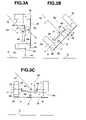
- the irradiation direction of the irradiation apparatus 1is fixed, the particle beam 1 a is applied in one direction, preferably obliquely from a position above the human (the patient) 3 and the patient 3 is rotated, furthermore, for example, as conceptionally shown in FIGS. 3A through 3C , the patient fixing device 4 for fixing the patient (not shown in FIGS. 3A through 3C ) is rotatable (tiltable) with respect to the floor surface (ground surface) G.
- the patient fixing device 4 for fixing the patientis rotatable (tiltable) with respect to the floor surface (ground surface) G.
- the CT scanner 2 and the patient fixing device 4are tiltable at the same angle with respect to the floor surface (ground surface) G, so that, as shown in FIG. 3B , when the patient fixing device 4 is in the state that is tilt with respect to the floor surface (ground surface) G, the patient fixing device 4 is inserted in the detection range 2 a of CT scanner 2 at the tilt angle as is and the CT scanning is possible in the tilt state.
- the above objectis attained by the construction in which the patient fixing device is rotated or moved so that it is possible to irradiate the affected area of the patient with the particle beam from many directions, by the patient fixing device which is movable between the particle beam irradiation apparatus and the CT scanner and the positionally confirming the affected area of the patient rotated or moved is possible.
- a particle beam irradiation systemincluding: a particle beam irradiation apparatus having a particle beam irradiator for irradiating an affected area of a patient with a particle beam from one direction, the particle beam irradiation apparatus being free of a gantry structure, the particle beam irradiator being housed in a chamber; a CT scanner installed in the chamber, for positionally confirming the affected area of the patient; a drive unit for moving the patient from a detection range of the CT scanner to an irradiation range of the particle beam irradiation apparatus; a patient fixing device for fixing the patient in position, the patient fixing device being mounted on said drive unit for rotation about the craniocaudal axis of the patient; and a housing unit having a structure housing the drive unit with the patient fixing device mounted and the CT scanner, the housing unit being rotatable about an axis perpendicular to a plane including a direction in which the particle beam is applied by
- a detection range of the CT scannermeans the central part (area, range) of the gantry of the CT scanner and “an irradiation range of the particle beam irradiation apparatus” means the part (area, range) which the particle beam passes in the treatment chamber.
- the particle beam irradiation apparatusapplies the particle beam obliquely to the affected area from a position above the affected area.
- the direction in which the particle beam is applied by the particle beam irradiation apparatus, the axis about which the housing unit is rotatable, and the craniocaudal axis about which the patient fixing device is rotatablecross each other at the affected area of the patient when the affected area is irradiated with the particle beam.
- FIG. 1is a schematic side elevational view of a particle beam irradiation system according to an embodiment of the present invention
- FIG. 2is a schematic view illustrative of a mode of axis rotation of the particle beam irradiation system
- FIGS. 3A through 3Care schematic side elevational views illustrative of another mode of axis rotation of the particle beam irradiation system.
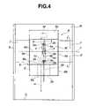
- FIG. 4is a front elevational view of the particle beam irradiation system.
- FIG. 1shows in schematic side elevation the particle beam irradiation system according to an embodiment of the present invention.
- the particle beam irradiation systemis installed in a treatment chamber R and includes a particle beam irradiation apparatus 1 , a CT scanner 2 , a patient fixing device 4 for fixing a patient 4 , a drive unit 5 for moving the patient fixing device 4 between an irradiation range of the particle beam irradiation apparatus 1 and a detection range 2 a of the CT scanner 2 , and a housing unit 6 storing therein the CT scanner 2 and the drive unit 5 with the patient fixing device 4 mounted thereon.
- the housing unit 6has opposite side walls which are positioned on the sides of the housing unit 6 that are respectively closer to and remoter from the viewer of FIG. 1 .
- these opposite side wallsare omitted from illustration in FIG. 1 .
- the particle beam irradiation apparatus 1may be a known particle beam irradiation apparatus insofar as it emits a particle beam 1 a such as a proton beam, a heavy ion beam, or the like from one direction.
- the particle beam irradiation apparatus 1may be the charged particle beam generator having the ion source, the preaccelerator, and the synchrotron disclosed in Patent Document 1, or the particle beam irradiation apparatus having the particle beam circularly accelerating means, the beam transporting means, and the irradiation field forming means disclosed in Patent Document 3.
- the particle beam irradiation apparatus 1is positioned such that it applies the particle beam 1 a in one direction to an affected area 3 a of a patient 3 fixed by the patient fixing device 4 .
- the direction x along which the particle beam 1 a is applied to the patient 3 on the patient fixing device 4should preferably be set such that the particle beam 1 a is applied obliquely to the affected area 3 a of the patient 3 from a position above the affected area 3 a of the patient 3 .
- An irradiation angle ⁇ at which the particle beam 1 a is applied to the patient 3 with respect to the horizontal plane Hshould preferably be about 45° or more preferably in a range of 45° ⁇ 30°.
- the particle beam irradiation apparatus 1 as a wholemay not be placed in the treatment chamber R, but at least a particle beam irradiator 1 b of the particle beam irradiation apparatus 1 should be housed in the treatment chamber R.
- the CT scanner 2may include a known CT scanner.
- the CT scanner 2is placed in an end of the housing unit 6 .
- the patient 3 placed on the patient fixing device 4 mounted on the drive unit 5can be inserted in the detection range 2 a of the CT scanner 2 .
- the CT scanner 2can be angularly moved to any desired angular position and set to any desired angle between a horizontal position parallel to a floor surface (ground surface) G (see FIGS. 3A through 3C ) and a vertical position perpendicular to the floor surface G, in unison with the drive unit 5 and an actuator M thereof.
- the patient fixing device 4 with the patient 3 held thereby in a given postureis mounted on the drive unit 5 .
- the patient fixing device 4may be detachably mounted on the drive unit 5 or may be fixedly mounted on the drive unit 5 .
- the patient fixing device 4is mounted on the drive unit 5 such that it can be rotated about the craniocaudal axis y of the patient 3 and can be angularly set to a desired angle about the craniocaudal axis y.
- the patient fixing device 4has a position adjusting function to adjust its position with respect to the drive unit 5 in the lateral and anteroposterior directions of the patient 3 for aligning the affected area 3 a of the patient 3 into accurate alignment with the irradiated spot of the particle beam 1 a .
- the patient fixing device 4may not have a position adjusting function to adjust its position with respect to the drive unit 5 in the craniocaudal directions of the patient 3 because the patient fixing device 4 can be positionally adjusted in the craniocaudal directions upon movement of the drive unit 5 .
- the patient fixing device 4has a pair of opposite bases 4 a and a fixing plate 4 b for fixing the patient 3 while holding the patient 3 in a given posture.
- the patient fixing device 4can be moved with the drive unit 5 in the craniocaudal directions of the patient 3 placed on the patient fixing device 4 .
- the patient fixing device 4is mounted on the drive unit 5 for rotation about the craniocaudal axis y of the patient 3 independently of the drive unit 5 .
- the patient fixing device 4may be rotated by any of various means. According to the illustrated embodiment, two support bases 5 a , which may be spaced about 2 m from each other in the vertical direction in FIG.
- the bases 4 a of the patient fixing device 4are rotatably connected to the respective support bases 5 a by respective pivot shafts 5 b .
- a stopis provided between the patient fixing device 4 and the drive unit 5 for locking the patient fixing device 4 in a desired angular position with respect to the drive unit 5 .
- the base 4 a of the patient fixing device 4which is positioned at the feet of the patient 3 on the patient fixing device 4 may be rotated as a turntable by an actuator, not shown, and the rotated base 4 a may be locked in a desired angular position by a locking unit, not shown.
- the patient fixing device 4may be rotated either by the drive unit 5 or manually. Further alternatively, a base 4 a , a support base 5 a , and a pivot shaft 5 b may be provided only at the feet of the patient 3 . When in actual use, the patient fixing device 4 may not be rotated through 360°, but may be controlled to make pendular motion with an amplitude selected for a better particle beam dose. Though the patient fixing device 4 may be made of any of various materials, it should preferably be made of a radiation-permeable material such as fiber-reinforced plastics, for example. The patient 3 may be fastened to the patient fixing device 4 by a fastening member such as a band, not shown.
- the patient fixing device 4has a position adjusting function to adjust its position with respect to the drive unit 5 in the lateral and anteroposterior directions of the patient 3 for aligning the affected area 3 a of the patient 3 into accurate alignment with the irradiated spot of the particle beam 1 a .
- the position adjusting functionmay be provided as follows:
- the support bases 5 ahave a plurality of holes (not shown) defined therein in a position adjustable range, and after the pivot shafts 5 b are inserted in selected ones of the holes in the support bases 5 a , the pivot shafts 5 b are secured to the support bases 5 a , thereby positionally adjusting the patient 3 in the lateral and anteroposterior directions thereof.
- the craniocaudal axis y of the patient 3 about which the patient fixing device 4 is rotatableshould extend through the affected area 3 a of the patient 3 .
- the fixing plate 4 b of the patient fixing device 4should preferably be positionally adjustable with respect to the rotational axis provided by the pivot shafts 5 b in order to allow the particle beam irradiation apparatus 1 to accurately irradiate various affected areas, such as tumors, of patients 3 .
- the fixing plate 4 bmay be slidably attached to the bases 4 a to positionally adjust the patient 3 such that the rotational axis provided by the pivot shafts 5 b passes through the affected area 3 a of the patient 3 fixed to the fixing plate 4 b .
- the bases 4 amay have a plurality of holes (not shown) defined therein in a position adjustable range, and the pivot shafts 5 b are inserted in selected ones of the holes in the bases 4 a in alignment with the affected area 3 a of the patient 3 secured to the fixing plate 4 b , so that the bases 4 a are rotatable about the pivot shafts 5 b.
- the drive unit 5serves to move the patient fixing device 4 between the irradiation range of the particle beam irradiation apparatus 1 and the detection range 2 a of the CT scanner 2 , as described above.
- the drive unit 5is housed in the housing unit 6 such that it has a front end (upper end in FIG. 1 ) disposed in a housing chamber 6 c of the housing unit 6 and a rear end (lower end in FIG. 1 ) extending through the detection range 2 a of the CT scanner 2 that is housed in a CT scanner housing chamber 6 b of the housing unit 6 .
- the drive unit 5can be angularly moved to any desired angular position and set to any desired angle between the horizontal position parallel to the floor surface (ground surface) G (see FIGS.
- the drive unit 5may be attached to the housing unit 6 by any of various means.
- the drive unit 5is coupled to the actuator M which is securely installed in the housing chamber 6 c of the housing unit 6 , so that the drive unit 5 is connected to the housing unit 6 .
- the patient fixing device 4is rotatably mounted on the drive unit 5 for rotation about the craniocaudal axis y of the patient 3 .
- the patient fixing device 4 , the CT scanner 2 , and the drive unit 5can be rotated and tilted about an axis z, which extends perpendicularly to the sheet of FIG. 1 , for pendular motion in unison with each other.
- the drive unit 5has an actuating means for moving the patient 3 secured to the patient fixing device 4 .
- the actuating meansis not limited to any actuating means, but may be of any of various means insofar as it can smoothly move the patient 3 secured to the patient fixing device 4 .
- the actuating meanshas a plate-line planar structure on which the patient fixing device 4 is mounted. The actuating means moves, with the actuator M through gears, not shown, the affected area 3 a of the patient 3 accurately from an image-capturing position (the detection range 2 a ) of the CT scanner 2 to an irradiation position (the irradiation range) of the particle beam irradiation apparatus 1 .
- the plate-like planar structure of the actuating means on which the patient fixing device 4 is mounted at a position 5 cmay be made of a material which does not obstruct the image-capturing operation of the CT scanner 2 .
- the plate-like planar structuremay be made of fiber-reinforced plastics, carbon fiber, or the like. Since the affected area 3 a of the patient 3 may be located anywhere in the patient 3 , e.g., the head or a lower leg, the drive unit 5 should be able to move the patient fixing device 4 over a distance preferably ranging from 1 m to 10 m or more preferably ranging from 2 m to 5 m.
- the housing unit 6is of a structure housing therein at least the drive unit 5 with the patient fixing device 4 mounted thereon and the CT scanner 2 .
- the CT scanner housing chamber 6 bwhich is disposed in an end (lower end in FIG. 1 ) of the housing unit 6 , houses the CT scanner 2 immovably therein.
- the CT scanner housing chamber 6 bhas a pair of openings 6 a defined respectively in opposite side walls (upper and lower side walls in FIG. 1 ) aligned with respective openings 2 b defined in respective opposite side walls (upper and lower side walls in FIG. 1 ) of the CT scanner 2 .
- the housing chamber 6 cwhich is disposed in an opposite end (upper end in FIG.
- the housing unit 6houses therein the actuator M for moving the patient 3 placed on the patient fixing device 4 along the craniocaudal axis y.
- the housing chamber 6 calso houses therein a counterbalance, not shown, which together with the actuator M balances the CT scanner 2 .
- the housing unit 6has an irradiation cavity 6 d defined between the CT scanning housing chamber 6 b and the housing chamber 6 c and open toward the particle beam irradiation apparatus 1 for allowing the particle beam irradiation apparatus 1 to apply the particle beam 1 a directly to the affected area 3 a of the patient 3 placed on the patient fixing device 4 .
- the patient fixing device 4 mounted on the drive unit 5is disposed in the irradiation cavity 6 d between the CT scanning housing chamber 6 b and the housing chamber 6 c .
- the housing unit 6may be of any structure for housing therein at least the drive unit 5 with the patient fixing device 4 mounted thereon and the CT scanner 2 .
- the CT scanner 2may directly be housed in the housing unit 6 such that the CT scanner 2 may have walls (upper and right walls in FIG. 1 ) fixed to a rear wall 6 f of the housing unit 6 (a wall confronting the irradiation opening 6 d ).
- the housing unit 6is rotatable about the axis z which extends perpendicularly to a plane (lying in the sheet of FIG. 1 ) which includes both the direction x in which the particle beam 1 a is applied and the direction w which the drive unit 5 moves. If the particle beam 1 a is applied obliquely to the affected area 3 a of the patient 3 from a position above the affected area 3 a as shown in FIG. 1 , then the axis z may be referred to as a horizontal axis (extending toward and away from the viewer of FIG. 1 ) perpendicular to the direction x along which the particle beam 1 a is applied to the patient 3 .
- the axis zis set so as to extend through the affected area 3 a of the patient 3 placed on the patient fixing device 4 .
- the axis zis set so as to extend through the affected area 3 a of the patient 3 placed on the patient fixing device 4 .
- the housing unit 6may be made rotatable by any of various means.
- opposite side walls 6 e of the housing unit 6are rotatably supported on respective opposite side walls 8 of the treatment chamber R (irradiation chamber) by respective shafts 7 , so that the housing unit 6 is suspended so as to be tiltable (rotatable) with respect to the floor surface (ground surface) G, and the shafts 7 have their central axes aligned with the axis z.
- the housing unit 6may be rotated or tilted for pendular motion with respect to the floor surface (ground surface) G by any of various rotating mechanisms.
- a combination of rotational componentssuch as gears and an actuator such as a motor may be used as such a rotating mechanism.
- the rotating mechanisms and the moving mechanisms employed in the present embodimentshould preferably be controllable by a computer and should also preferably be manually adjustable.
- the housing unit 6may be made of any of various materials insofar as it is strong enough to house the CT scanner 2 therein and withstand rotation of the housing unit 6 .
- the shafts 7are made of a material strong enough, and have a diameter large enough, to support the housing unit 6 in suspension and allow the housing unit 6 to rotate.
- the shafts 7should preferably be adjustable in height and position with respect to the housing unit 6 .
- the housing unit 6should desirably be of such a height as to allow the lower part of the body of the patient in an upstanding posture to be irradiated with the particle beam 1 a and inspected by the CT scanner 2 .
- the housing unit 6is angularly movable about the axis of the shafts 7 to allow the housing unit 6 which houses the CT scanner 2 , the drive unit 5 with the patient fixing device 4 mounted thereon, and the actuator M to be set to any of various angles with respect to the particle beam 1 a , as shown in FIGS. 3A through 3C .
- the housing unit 6may be angularly moved through any angle suitable for giving a better radiation dose distribution to the patient 3 placed on the patient fixing device 4 that is mounted on the drive unit 5 .
- the housing unit 6should be angularly movable in an angular range from 0° to 90° with respect to the floor surface (ground surface) G, i.e., in an angular range from the angular position shown in FIG. 3A to the angular position shown in FIG. 3C .
- the opposite side walls of the housing unit 6are omitted from illustration.
- the weights of the CT scanner 2 and the actuator M combined with the counterbalanceshould be held in equilibrium, as described above.
- the particle beam irradiation system Aoperates as follows: First, the particle beam irradiation system A is set to have the central axis of the particle beam 1 a positioned in exact alignment with a transversely central area of the drive unit 5 . Then, the patient fixing device 4 is positionally adjusted to position the affected area 3 a of the patient 3 substantially in alignment with the transversely central area of the drive unit 5 . Thereafter, the drive unit 5 is actuated to bring the affected area 3 a into the detection range 2 a of the CT scanner 2 .
- the patient fixing device 4is positionally adjusted in the lateral and anteroposterior directions of the patient 3 with respect to the drive unit 5 to accurately keep the affected area 3 a in alignment with the transversely central area of the drive unit 5 .
- the drive unit 5is actuated to aim the irradiated spot of the particle beam 1 a at the affected area 3 a .
- the particle beam irradiation apparatus 1is energized to irradiate the affected area 3 a with the particle beam 1 a .
- the above processrepresents a basic therapeutic process performed by the particle beam irradiation system A.
- the patient fixing device 4is rotated about the craniocaudal axis y of the patient 3 to aim the particle beam 1 a not only at a front side of the patient 3 , but also at either lateral side of the patient 3 , as shown in FIG. 2 , and the housing unit 6 is rotated about the axis z to aim the particle beam 1 a at the affected area 3 a in a wide craniocaudal range.
- These rotary motions of the patient fixing device 4 and the housing unit 6may be combined with each other to allow the particle beam irradiation apparatus 1 to apply the particle beam 1 a to the affected area 3 a from various directions in a three-dimensional space.
- the patient 3 placed on the patient fixing device 4can be rotated about two axes, and the particle beam 1 a emitted from the particle beam irradiation apparatus 1 can be applied in multiple field irradiation without the need for a rotary gantry structure to be incorporated into the particle beam irradiation apparatus 1 .
- the position of the patient 3can be confirmed again by the CT scanner 2 and then the patient 3 can be irradiated with the particle beam 1 a . Therefore, the patient 3 can be irradiated with the particle beam 1 a with high positional accuracy for excellent therapeutic outcomes.
Landscapes
- Health & Medical Sciences (AREA)
- Engineering & Computer Science (AREA)
- Biomedical Technology (AREA)
- Pathology (AREA)
- Nuclear Medicine, Radiotherapy & Molecular Imaging (AREA)
- Radiology & Medical Imaging (AREA)
- Life Sciences & Earth Sciences (AREA)
- Animal Behavior & Ethology (AREA)
- General Health & Medical Sciences (AREA)
- Public Health (AREA)
- Veterinary Medicine (AREA)
- Radiation-Therapy Devices (AREA)
- Apparatus For Radiation Diagnosis (AREA)
- Superconductors And Manufacturing Methods Therefor (AREA)
- Pit Excavations, Shoring, Fill Or Stabilisation Of Slopes (AREA)
Abstract
Description
Claims (13)
Applications Claiming Priority (2)
| Application Number | Priority Date | Filing Date | Title |
|---|---|---|---|
| JP2007-039359 | 2007-02-20 | ||
| JP2007039359AJP4936924B2 (en) | 2007-02-20 | 2007-02-20 | Particle beam irradiation system |
Publications (2)
| Publication Number | Publication Date |
|---|---|
| US20080197296A1 US20080197296A1 (en) | 2008-08-21 |
| US7659528B2true US7659528B2 (en) | 2010-02-09 |
Family
ID=38667031
Family Applications (1)
| Application Number | Title | Priority Date | Filing Date |
|---|---|---|---|
| US11/896,090Expired - Fee RelatedUS7659528B2 (en) | 2007-02-20 | 2007-08-29 | Particle beam irradiation system |
Country Status (5)
| Country | Link |
|---|---|
| US (1) | US7659528B2 (en) |
| EP (1) | EP1961445B1 (en) |
| JP (1) | JP4936924B2 (en) |
| AT (1) | ATE451949T1 (en) |
| DE (1) | DE602007003801D1 (en) |
Cited By (33)
| Publication number | Priority date | Publication date | Assignee | Title |
|---|---|---|---|---|
| US20100045213A1 (en)* | 2004-07-21 | 2010-02-25 | Still River Systems, Inc. | Programmable Radio Frequency Waveform Generator for a Synchrocyclotron |
| US8791656B1 (en) | 2013-05-31 | 2014-07-29 | Mevion Medical Systems, Inc. | Active return system |
| US8907311B2 (en) | 2005-11-18 | 2014-12-09 | Mevion Medical Systems, Inc. | Charged particle radiation therapy |
| US8927950B2 (en) | 2012-09-28 | 2015-01-06 | Mevion Medical Systems, Inc. | Focusing a particle beam |
| US8933650B2 (en) | 2007-11-30 | 2015-01-13 | Mevion Medical Systems, Inc. | Matching a resonant frequency of a resonant cavity to a frequency of an input voltage |
| US8941083B2 (en) | 2007-10-11 | 2015-01-27 | Mevion Medical Systems, Inc. | Applying a particle beam to a patient |
| US8970137B2 (en) | 2007-11-30 | 2015-03-03 | Mevion Medical Systems, Inc. | Interrupted particle source |
| US9155186B2 (en) | 2012-09-28 | 2015-10-06 | Mevion Medical Systems, Inc. | Focusing a particle beam using magnetic field flutter |
| US9185789B2 (en) | 2012-09-28 | 2015-11-10 | Mevion Medical Systems, Inc. | Magnetic shims to alter magnetic fields |
| US9196082B2 (en) | 2008-02-22 | 2015-11-24 | Loma Linda University Medical Center | Systems and methods for characterizing spatial distortion in 3D imaging systems |
| US9213107B2 (en) | 2009-10-01 | 2015-12-15 | Loma Linda University Medical Center | Ion induced impact ionization detector and uses thereof |
| US9301384B2 (en) | 2012-09-28 | 2016-03-29 | Mevion Medical Systems, Inc. | Adjusting energy of a particle beam |
| US9545528B2 (en) | 2012-09-28 | 2017-01-17 | Mevion Medical Systems, Inc. | Controlling particle therapy |
| US9622335B2 (en) | 2012-09-28 | 2017-04-11 | Mevion Medical Systems, Inc. | Magnetic field regenerator |
| US9661736B2 (en) | 2014-02-20 | 2017-05-23 | Mevion Medical Systems, Inc. | Scanning system for a particle therapy system |
| US9681531B2 (en) | 2012-09-28 | 2017-06-13 | Mevion Medical Systems, Inc. | Control system for a particle accelerator |
| US9723705B2 (en) | 2012-09-28 | 2017-08-01 | Mevion Medical Systems, Inc. | Controlling intensity of a particle beam |
| US9730308B2 (en) | 2013-06-12 | 2017-08-08 | Mevion Medical Systems, Inc. | Particle accelerator that produces charged particles having variable energies |
| USD810297S1 (en)* | 2016-03-25 | 2018-02-13 | Mitsubishi Electric Corporation | Radiation irradiator for particle beam treatment equipment |
| USD810298S1 (en)* | 2016-03-25 | 2018-02-13 | Mitsubishi Electric Corporation | Radiation irradiator for particle beam treatment equipment |
| USD815742S1 (en)* | 2016-03-25 | 2018-04-17 | Mitsubishi Electric Corporation | Radiation irradiator for particle beam treatment equipment |
| US9950194B2 (en) | 2014-09-09 | 2018-04-24 | Mevion Medical Systems, Inc. | Patient positioning system |
| USD816845S1 (en)* | 2016-03-25 | 2018-05-01 | Mitsubishi Electric Corporation | Radiation irradiator for particle beam treatment equipment |
| US9962560B2 (en) | 2013-12-20 | 2018-05-08 | Mevion Medical Systems, Inc. | Collimator and energy degrader |
| US10254739B2 (en) | 2012-09-28 | 2019-04-09 | Mevion Medical Systems, Inc. | Coil positioning system |
| US10258810B2 (en) | 2013-09-27 | 2019-04-16 | Mevion Medical Systems, Inc. | Particle beam scanning |
| US10278593B2 (en) | 2012-06-21 | 2019-05-07 | Siemens Healthcare Gmbh | Adaptive control of monitoring devices |
| US10646728B2 (en) | 2015-11-10 | 2020-05-12 | Mevion Medical Systems, Inc. | Adaptive aperture |
| US10653892B2 (en) | 2017-06-30 | 2020-05-19 | Mevion Medical Systems, Inc. | Configurable collimator controlled using linear motors |
| US10675487B2 (en) | 2013-12-20 | 2020-06-09 | Mevion Medical Systems, Inc. | Energy degrader enabling high-speed energy switching |
| US10925147B2 (en) | 2016-07-08 | 2021-02-16 | Mevion Medical Systems, Inc. | Treatment planning |
| US11103730B2 (en) | 2017-02-23 | 2021-08-31 | Mevion Medical Systems, Inc. | Automated treatment in particle therapy |
| US11291861B2 (en) | 2019-03-08 | 2022-04-05 | Mevion Medical Systems, Inc. | Delivery of radiation by column and generating a treatment plan therefor |
Families Citing this family (7)
| Publication number | Priority date | Publication date | Assignee | Title |
|---|---|---|---|---|
| US20090281383A1 (en)* | 2005-09-08 | 2009-11-12 | Rao Papineni | Apparatus and method for external fluorescence imaging of internal regions of interest in a small animal using an endoscope for internal illumination |
| US8203132B2 (en)* | 2005-09-08 | 2012-06-19 | Carestream Health, Inc. | Apparatus and method for imaging ionizing radiation |
| US20100220836A1 (en) | 2005-09-08 | 2010-09-02 | Feke Gilbert D | Apparatus and method for multi-modal imaging |
| US8660631B2 (en)* | 2005-09-08 | 2014-02-25 | Bruker Biospin Corporation | Torsional support apparatus and method for craniocaudal rotation of animals |
| JP5430115B2 (en)* | 2008-10-15 | 2014-02-26 | 三菱電機株式会社 | Scanning irradiation equipment for charged particle beam |
| BRPI0924903B8 (en)* | 2009-03-04 | 2021-06-22 | Zakrytoe Aktsionernoe Obshchestvo Protom | apparatus for generating a negative ion beam for use in charged particle radiation therapy and method for generating a negative ion beam for use with charged particle radiation therapy |
| JP7082366B2 (en)* | 2018-03-23 | 2022-06-08 | 株式会社日立製作所 | Radiation therapy device, bed positioning device, and bed positioning method |
Citations (16)
| Publication number | Priority date | Publication date | Assignee | Title |
|---|---|---|---|---|
| US4726046A (en)* | 1985-11-05 | 1988-02-16 | Varian Associates, Inc. | X-ray and electron radiotherapy clinical treatment machine |
| US5117829A (en)* | 1989-03-31 | 1992-06-02 | Loma Linda University Medical Center | Patient alignment system and procedure for radiation treatment |
| US5329567A (en)* | 1992-03-24 | 1994-07-12 | Jun Ikebe | System for stereotactic radiotherapy with a computerized tomographic scanning system |
| JPH09192244A (en) | 1996-01-18 | 1997-07-29 | Mitsubishi Electric Corp | Particle beam irradiation device |
| US5912943A (en)* | 1997-11-26 | 1999-06-15 | Picker International, Inc. | Cooling system for a sealed housing positioned in a sterile environment |
| US6007243A (en)* | 1996-02-21 | 1999-12-28 | Lunar Corporation | Combined mobile x-ray imaging system and monitor cart |
| US6094760A (en) | 1997-08-04 | 2000-08-01 | Sumitomo Heavy Industries, Ltd. | Bed system for radiation therapy |
| US6205347B1 (en)* | 1998-02-27 | 2001-03-20 | Picker International, Inc. | Separate and combined multi-modality diagnostic imaging system |
| JP2003190304A (en) | 2001-12-26 | 2003-07-08 | Mitsubishi Electric Corp | Particle beam therapy system |
| US6666579B2 (en)* | 2000-12-28 | 2003-12-23 | Ge Medical Systems Global Technology Company, Llc | Method and apparatus for obtaining and displaying computed tomography images using a fluoroscopy imaging system |
| US20040034438A1 (en)* | 2002-08-14 | 2004-02-19 | Minoru Uematsu | Composite system for radiation therapy |
| WO2005018734A2 (en) | 2003-08-12 | 2005-03-03 | Loma Linda University Medical Center | Patient positioning system for radiation therapy system |
| EP1683545A2 (en) | 2005-01-24 | 2006-07-26 | Hitachi, Ltd. | Ion beam therapy system and couch positioning method |
| JP2006218315A (en) | 2006-05-01 | 2006-08-24 | Hitachi Ltd | Bed positioning apparatus, positioning method therefor, and particle beam therapy apparatus |
| US7173265B2 (en)* | 2003-08-12 | 2007-02-06 | Loma Linda University Medical Center | Modular patient support system |
| US7425717B2 (en)* | 2003-05-13 | 2008-09-16 | Hitachi, Ltd. | Particle beam irradiation apparatus, treatment planning unit, and particle beam irradiation method |
Family Cites Families (4)
| Publication number | Priority date | Publication date | Assignee | Title |
|---|---|---|---|---|
| JPH0780088A (en)* | 1993-09-20 | 1995-03-28 | Mitsubishi Electric Corp | Radiation therapy equipment |
| JP3577221B2 (en)* | 1997-08-04 | 2004-10-13 | 住友重機械工業株式会社 | Radiation therapy bed system |
| JP3751440B2 (en)* | 1998-04-30 | 2006-03-01 | 三菱電機株式会社 | Particle beam therapy system |
| JP3961464B2 (en)* | 2002-08-14 | 2007-08-22 | 稔 植松 | Radiotherapy compound device |
- 2007
- 2007-02-20JPJP2007039359Apatent/JP4936924B2/ennot_activeExpired - Fee Related
- 2007-08-29USUS11/896,090patent/US7659528B2/ennot_activeExpired - Fee Related
- 2007-09-06ATAT07253524Tpatent/ATE451949T1/ennot_activeIP Right Cessation
- 2007-09-06EPEP07253524Apatent/EP1961445B1/ennot_activeNot-in-force
- 2007-09-06DEDE602007003801Tpatent/DE602007003801D1/enactiveActive
Patent Citations (17)
| Publication number | Priority date | Publication date | Assignee | Title |
|---|---|---|---|---|
| US4726046A (en)* | 1985-11-05 | 1988-02-16 | Varian Associates, Inc. | X-ray and electron radiotherapy clinical treatment machine |
| US5117829A (en)* | 1989-03-31 | 1992-06-02 | Loma Linda University Medical Center | Patient alignment system and procedure for radiation treatment |
| US5329567A (en)* | 1992-03-24 | 1994-07-12 | Jun Ikebe | System for stereotactic radiotherapy with a computerized tomographic scanning system |
| JPH09192244A (en) | 1996-01-18 | 1997-07-29 | Mitsubishi Electric Corp | Particle beam irradiation device |
| US6007243A (en)* | 1996-02-21 | 1999-12-28 | Lunar Corporation | Combined mobile x-ray imaging system and monitor cart |
| US6094760A (en) | 1997-08-04 | 2000-08-01 | Sumitomo Heavy Industries, Ltd. | Bed system for radiation therapy |
| US5912943A (en)* | 1997-11-26 | 1999-06-15 | Picker International, Inc. | Cooling system for a sealed housing positioned in a sterile environment |
| US6205347B1 (en)* | 1998-02-27 | 2001-03-20 | Picker International, Inc. | Separate and combined multi-modality diagnostic imaging system |
| US6666579B2 (en)* | 2000-12-28 | 2003-12-23 | Ge Medical Systems Global Technology Company, Llc | Method and apparatus for obtaining and displaying computed tomography images using a fluoroscopy imaging system |
| JP2003190304A (en) | 2001-12-26 | 2003-07-08 | Mitsubishi Electric Corp | Particle beam therapy system |
| US20040034438A1 (en)* | 2002-08-14 | 2004-02-19 | Minoru Uematsu | Composite system for radiation therapy |
| US7425717B2 (en)* | 2003-05-13 | 2008-09-16 | Hitachi, Ltd. | Particle beam irradiation apparatus, treatment planning unit, and particle beam irradiation method |
| WO2005018734A2 (en) | 2003-08-12 | 2005-03-03 | Loma Linda University Medical Center | Patient positioning system for radiation therapy system |
| US7173265B2 (en)* | 2003-08-12 | 2007-02-06 | Loma Linda University Medical Center | Modular patient support system |
| US7199382B2 (en)* | 2003-08-12 | 2007-04-03 | Loma Linda University Medical Center | Patient alignment system with external measurement and object coordination for radiation therapy system |
| EP1683545A2 (en) | 2005-01-24 | 2006-07-26 | Hitachi, Ltd. | Ion beam therapy system and couch positioning method |
| JP2006218315A (en) | 2006-05-01 | 2006-08-24 | Hitachi Ltd | Bed positioning apparatus, positioning method therefor, and particle beam therapy apparatus |
Non-Patent Citations (1)
| Title |
|---|
| T. Kamada et al., "A horizontal CT system dedicated to heavy-ion beam treatment", Radiotherapy and Oncology, Elsevier, vol. 50, No. 2, (Feb. 1999) pp. 235-237. |
Cited By (55)
| Publication number | Priority date | Publication date | Assignee | Title |
|---|---|---|---|---|
| USRE48047E1 (en) | 2004-07-21 | 2020-06-09 | Mevion Medical Systems, Inc. | Programmable radio frequency waveform generator for a synchrocyclotron |
| US20100045213A1 (en)* | 2004-07-21 | 2010-02-25 | Still River Systems, Inc. | Programmable Radio Frequency Waveform Generator for a Synchrocyclotron |
| US8952634B2 (en) | 2004-07-21 | 2015-02-10 | Mevion Medical Systems, Inc. | Programmable radio frequency waveform generator for a synchrocyclotron |
| US9452301B2 (en) | 2005-11-18 | 2016-09-27 | Mevion Medical Systems, Inc. | Inner gantry |
| US8907311B2 (en) | 2005-11-18 | 2014-12-09 | Mevion Medical Systems, Inc. | Charged particle radiation therapy |
| US8916843B2 (en) | 2005-11-18 | 2014-12-23 | Mevion Medical Systems, Inc. | Inner gantry |
| US9925395B2 (en) | 2005-11-18 | 2018-03-27 | Mevion Medical Systems, Inc. | Inner gantry |
| US10279199B2 (en) | 2005-11-18 | 2019-05-07 | Mevion Medical Systems, Inc. | Inner gantry |
| US10722735B2 (en) | 2005-11-18 | 2020-07-28 | Mevion Medical Systems, Inc. | Inner gantry |
| US8941083B2 (en) | 2007-10-11 | 2015-01-27 | Mevion Medical Systems, Inc. | Applying a particle beam to a patient |
| US8970137B2 (en) | 2007-11-30 | 2015-03-03 | Mevion Medical Systems, Inc. | Interrupted particle source |
| USRE48317E1 (en) | 2007-11-30 | 2020-11-17 | Mevion Medical Systems, Inc. | Interrupted particle source |
| US8933650B2 (en) | 2007-11-30 | 2015-01-13 | Mevion Medical Systems, Inc. | Matching a resonant frequency of a resonant cavity to a frequency of an input voltage |
| US9196082B2 (en) | 2008-02-22 | 2015-11-24 | Loma Linda University Medical Center | Systems and methods for characterizing spatial distortion in 3D imaging systems |
| US9213107B2 (en) | 2009-10-01 | 2015-12-15 | Loma Linda University Medical Center | Ion induced impact ionization detector and uses thereof |
| US10278593B2 (en) | 2012-06-21 | 2019-05-07 | Siemens Healthcare Gmbh | Adaptive control of monitoring devices |
| US9545528B2 (en) | 2012-09-28 | 2017-01-17 | Mevion Medical Systems, Inc. | Controlling particle therapy |
| US9622335B2 (en) | 2012-09-28 | 2017-04-11 | Mevion Medical Systems, Inc. | Magnetic field regenerator |
| US9681531B2 (en) | 2012-09-28 | 2017-06-13 | Mevion Medical Systems, Inc. | Control system for a particle accelerator |
| US9706636B2 (en) | 2012-09-28 | 2017-07-11 | Mevion Medical Systems, Inc. | Adjusting energy of a particle beam |
| US9723705B2 (en) | 2012-09-28 | 2017-08-01 | Mevion Medical Systems, Inc. | Controlling intensity of a particle beam |
| US10155124B2 (en) | 2012-09-28 | 2018-12-18 | Mevion Medical Systems, Inc. | Controlling particle therapy |
| US9155186B2 (en) | 2012-09-28 | 2015-10-06 | Mevion Medical Systems, Inc. | Focusing a particle beam using magnetic field flutter |
| US9185789B2 (en) | 2012-09-28 | 2015-11-10 | Mevion Medical Systems, Inc. | Magnetic shims to alter magnetic fields |
| US8927950B2 (en) | 2012-09-28 | 2015-01-06 | Mevion Medical Systems, Inc. | Focusing a particle beam |
| US10254739B2 (en) | 2012-09-28 | 2019-04-09 | Mevion Medical Systems, Inc. | Coil positioning system |
| US10368429B2 (en) | 2012-09-28 | 2019-07-30 | Mevion Medical Systems, Inc. | Magnetic field regenerator |
| US9301384B2 (en) | 2012-09-28 | 2016-03-29 | Mevion Medical Systems, Inc. | Adjusting energy of a particle beam |
| US8791656B1 (en) | 2013-05-31 | 2014-07-29 | Mevion Medical Systems, Inc. | Active return system |
| US9730308B2 (en) | 2013-06-12 | 2017-08-08 | Mevion Medical Systems, Inc. | Particle accelerator that produces charged particles having variable energies |
| US10456591B2 (en) | 2013-09-27 | 2019-10-29 | Mevion Medical Systems, Inc. | Particle beam scanning |
| US10258810B2 (en) | 2013-09-27 | 2019-04-16 | Mevion Medical Systems, Inc. | Particle beam scanning |
| US10675487B2 (en) | 2013-12-20 | 2020-06-09 | Mevion Medical Systems, Inc. | Energy degrader enabling high-speed energy switching |
| US9962560B2 (en) | 2013-12-20 | 2018-05-08 | Mevion Medical Systems, Inc. | Collimator and energy degrader |
| US10434331B2 (en) | 2014-02-20 | 2019-10-08 | Mevion Medical Systems, Inc. | Scanning system |
| US9661736B2 (en) | 2014-02-20 | 2017-05-23 | Mevion Medical Systems, Inc. | Scanning system for a particle therapy system |
| US11717700B2 (en) | 2014-02-20 | 2023-08-08 | Mevion Medical Systems, Inc. | Scanning system |
| US9950194B2 (en) | 2014-09-09 | 2018-04-24 | Mevion Medical Systems, Inc. | Patient positioning system |
| US10786689B2 (en) | 2015-11-10 | 2020-09-29 | Mevion Medical Systems, Inc. | Adaptive aperture |
| US11786754B2 (en) | 2015-11-10 | 2023-10-17 | Mevion Medical Systems, Inc. | Adaptive aperture |
| US10646728B2 (en) | 2015-11-10 | 2020-05-12 | Mevion Medical Systems, Inc. | Adaptive aperture |
| US11213697B2 (en) | 2015-11-10 | 2022-01-04 | Mevion Medical Systems, Inc. | Adaptive aperture |
| USD810297S1 (en)* | 2016-03-25 | 2018-02-13 | Mitsubishi Electric Corporation | Radiation irradiator for particle beam treatment equipment |
| USD810298S1 (en)* | 2016-03-25 | 2018-02-13 | Mitsubishi Electric Corporation | Radiation irradiator for particle beam treatment equipment |
| USD815742S1 (en)* | 2016-03-25 | 2018-04-17 | Mitsubishi Electric Corporation | Radiation irradiator for particle beam treatment equipment |
| USD816845S1 (en)* | 2016-03-25 | 2018-05-01 | Mitsubishi Electric Corporation | Radiation irradiator for particle beam treatment equipment |
| US10925147B2 (en) | 2016-07-08 | 2021-02-16 | Mevion Medical Systems, Inc. | Treatment planning |
| US12150235B2 (en) | 2016-07-08 | 2024-11-19 | Mevion Medical Systems, Inc. | Treatment planning |
| US11103730B2 (en) | 2017-02-23 | 2021-08-31 | Mevion Medical Systems, Inc. | Automated treatment in particle therapy |
| US10653892B2 (en) | 2017-06-30 | 2020-05-19 | Mevion Medical Systems, Inc. | Configurable collimator controlled using linear motors |
| US11717703B2 (en) | 2019-03-08 | 2023-08-08 | Mevion Medical Systems, Inc. | Delivery of radiation by column and generating a treatment plan therefor |
| US11311746B2 (en) | 2019-03-08 | 2022-04-26 | Mevion Medical Systems, Inc. | Collimator and energy degrader for a particle therapy system |
| US11291861B2 (en) | 2019-03-08 | 2022-04-05 | Mevion Medical Systems, Inc. | Delivery of radiation by column and generating a treatment plan therefor |
| US12161885B2 (en) | 2019-03-08 | 2024-12-10 | Mevion Medical Systems, Inc. | Delivery of radiation by column and generating a treatment plan therefor |
| US12168147B2 (en) | 2019-03-08 | 2024-12-17 | Mevion Medical Systems, Inc. | Collimator and energy degrader for a particle therapy system |
Also Published As
| Publication number | Publication date |
|---|---|
| DE602007003801D1 (en) | 2010-01-28 |
| JP2008200264A (en) | 2008-09-04 |
| ATE451949T1 (en) | 2010-01-15 |
| EP1961445B1 (en) | 2009-12-16 |
| JP4936924B2 (en) | 2012-05-23 |
| US20080197296A1 (en) | 2008-08-21 |
| EP1961445A1 (en) | 2008-08-27 |
Similar Documents
| Publication | Publication Date | Title |
|---|---|---|
| US7659528B2 (en) | Particle beam irradiation system | |
| EP0776637B1 (en) | Stereotactic radiosurgery | |
| JP4549604B2 (en) | Ion beam system for irradiating tumor tissue | |
| JP3305348B2 (en) | Stereotactic radiotherapy device | |
| JP5950575B2 (en) | Treatment of patient tumors with charged particle therapy | |
| US8053745B2 (en) | Device and method for administering particle beam therapy | |
| US20090056022A1 (en) | Patient support device | |
| JP2001346893A (en) | Radiotherapy equipment | |
| CA2634071A1 (en) | Radiation treatment apparatus | |
| US12226658B2 (en) | Radiation therapy system and method of operating radiation therapy apparatus | |
| JPH11313900A (en) | Radiation therapy bed system | |
| US20200114173A1 (en) | Radiotherapy system and method using the same | |
| CN103170067A (en) | Method for correctively adjusting a beam for irradiating a moving target volume | |
| US7899155B2 (en) | Stand for holding a radiation detector for a radiation therapy device | |
| JP2004065808A (en) | Radiotherapeutic system | |
| JP7082366B2 (en) | Radiation therapy device, bed positioning device, and bed positioning method | |
| JP3825384B2 (en) | Radiotherapy apparatus and method of operating the same | |
| JP6858027B2 (en) | Treatment table | |
| JP2593412Y2 (en) | Stereotactic radiotherapy device | |
| JP2004167000A (en) | Radiotherapy instrument | |
| JPH0739592A (en) | Radiation therapy equipment | |
| JP2003334260A (en) | Target moving type apparatus for particle beam irradiation | |
| EP3388109B1 (en) | Gantry system for particle beam therapy | |
| JP2022083625A (en) | Charged particle beam therapy device | |
| HK1262305A1 (en) | Gantry system for particle beam therapy |
Legal Events
| Date | Code | Title | Description |
|---|---|---|---|
| AS | Assignment | Owner name:UEMATSU, MINORU,JAPAN Free format text:ASSIGNMENT OF ASSIGNORS INTEREST;ASSIGNOR:UEMATSU, MINORU;REEL/FRAME:019808/0573 Effective date:20070808 Owner name:UEMATSU, MINORU, JAPAN Free format text:ASSIGNMENT OF ASSIGNORS INTEREST;ASSIGNOR:UEMATSU, MINORU;REEL/FRAME:019808/0573 Effective date:20070808 | |
| AS | Assignment | Owner name:WONG, JAMES ROBERT,NEW JERSEY Free format text:CORRECTIVE ASSIGNMENT TO CORRECT THE LISTING OF THE ASSIGNEES PREVIOUSLY RECORDED ON REEL 019808 FRAME 0573. ASSIGNOR(S) HEREBY CONFIRMS THE ASSIGNEES SHOULD BE MINORU UEMATSU, MASAYUKI ATSUCHI AND JAMES ROBERT WONG.;ASSIGNOR:UEMATSU, MINORU;REEL/FRAME:023544/0077 Effective date:20070808 Owner name:ATSUCHI, MASAYUKI,JAPAN Free format text:CORRECTIVE ASSIGNMENT TO CORRECT THE LISTING OF THE ASSIGNEES PREVIOUSLY RECORDED ON REEL 019808 FRAME 0573. ASSIGNOR(S) HEREBY CONFIRMS THE ASSIGNEES SHOULD BE MINORU UEMATSU, MASAYUKI ATSUCHI AND JAMES ROBERT WONG.;ASSIGNOR:UEMATSU, MINORU;REEL/FRAME:023544/0077 Effective date:20070808 Owner name:UEMATSU, MINORU,JAPAN Free format text:CORRECTIVE ASSIGNMENT TO CORRECT THE LISTING OF THE ASSIGNEES PREVIOUSLY RECORDED ON REEL 019808 FRAME 0573. ASSIGNOR(S) HEREBY CONFIRMS THE ASSIGNEES SHOULD BE MINORU UEMATSU, MASAYUKI ATSUCHI AND JAMES ROBERT WONG.;ASSIGNOR:UEMATSU, MINORU;REEL/FRAME:023544/0077 Effective date:20070808 Owner name:WONG, JAMES ROBERT, NEW JERSEY Free format text:CORRECTIVE ASSIGNMENT TO CORRECT THE LISTING OF THE ASSIGNEES PREVIOUSLY RECORDED ON REEL 019808 FRAME 0573;ASSIGNOR:UEMATSU, MINORU;REEL/FRAME:023544/0077 Effective date:20070808 Owner name:ATSUCHI, MASAYUKI, JAPAN Free format text:CORRECTIVE ASSIGNMENT TO CORRECT THE LISTING OF THE ASSIGNEES PREVIOUSLY RECORDED ON REEL 019808 FRAME 0573;ASSIGNOR:UEMATSU, MINORU;REEL/FRAME:023544/0077 Effective date:20070808 Owner name:UEMATSU, MINORU, JAPAN Free format text:CORRECTIVE ASSIGNMENT TO CORRECT THE LISTING OF THE ASSIGNEES PREVIOUSLY RECORDED ON REEL 019808 FRAME 0573;ASSIGNOR:UEMATSU, MINORU;REEL/FRAME:023544/0077 Effective date:20070808 | |
| STCF | Information on status: patent grant | Free format text:PATENTED CASE | |
| FEPP | Fee payment procedure | Free format text:PAYOR NUMBER ASSIGNED (ORIGINAL EVENT CODE: ASPN); ENTITY STATUS OF PATENT OWNER: LARGE ENTITY | |
| FPAY | Fee payment | Year of fee payment:4 | |
| FPAY | Fee payment | Year of fee payment:8 | |
| FEPP | Fee payment procedure | Free format text:MAINTENANCE FEE REMINDER MAILED (ORIGINAL EVENT CODE: REM.); ENTITY STATUS OF PATENT OWNER: LARGE ENTITY | |
| LAPS | Lapse for failure to pay maintenance fees | Free format text:PATENT EXPIRED FOR FAILURE TO PAY MAINTENANCE FEES (ORIGINAL EVENT CODE: EXP.); ENTITY STATUS OF PATENT OWNER: LARGE ENTITY | |
| STCH | Information on status: patent discontinuation | Free format text:PATENT EXPIRED DUE TO NONPAYMENT OF MAINTENANCE FEES UNDER 37 CFR 1.362 | |
| FP | Lapsed due to failure to pay maintenance fee | Effective date:20220209 |