US7658767B2 - Hinged orthopaedic prosthesis - Google Patents
Hinged orthopaedic prosthesisDownload PDFInfo
- Publication number
- US7658767B2 US7658767B2US11/428,066US42806606AUS7658767B2US 7658767 B2US7658767 B2US 7658767B2US 42806606 AUS42806606 AUS 42806606AUS 7658767 B2US7658767 B2US 7658767B2
- Authority
- US
- United States
- Prior art keywords
- component
- bearing
- femoral component
- knee prosthesis
- femoral
- Prior art date
- Legal status (The legal status is an assumption and is not a legal conclusion. Google has not performed a legal analysis and makes no representation as to the accuracy of the status listed.)
- Active, expires
Links
Images


Classifications
- A—HUMAN NECESSITIES
- A61—MEDICAL OR VETERINARY SCIENCE; HYGIENE
- A61F—FILTERS IMPLANTABLE INTO BLOOD VESSELS; PROSTHESES; DEVICES PROVIDING PATENCY TO, OR PREVENTING COLLAPSING OF, TUBULAR STRUCTURES OF THE BODY, e.g. STENTS; ORTHOPAEDIC, NURSING OR CONTRACEPTIVE DEVICES; FOMENTATION; TREATMENT OR PROTECTION OF EYES OR EARS; BANDAGES, DRESSINGS OR ABSORBENT PADS; FIRST-AID KITS
- A61F2/00—Filters implantable into blood vessels; Prostheses, i.e. artificial substitutes or replacements for parts of the body; Appliances for connecting them with the body; Devices providing patency to, or preventing collapsing of, tubular structures of the body, e.g. stents
- A61F2/02—Prostheses implantable into the body
- A61F2/30—Joints
- A61F2/38—Joints for elbows or knees
- A61F2/3836—Special connection between upper and lower leg, e.g. constrained
- A61F2/384—Special connection between upper and lower leg, e.g. constrained hinged, i.e. with transverse axle restricting the movement
- A61F2/385—Special connection between upper and lower leg, e.g. constrained hinged, i.e. with transverse axle restricting the movement also provided with condylar bearing surfaces
- A—HUMAN NECESSITIES
- A61—MEDICAL OR VETERINARY SCIENCE; HYGIENE
- A61F—FILTERS IMPLANTABLE INTO BLOOD VESSELS; PROSTHESES; DEVICES PROVIDING PATENCY TO, OR PREVENTING COLLAPSING OF, TUBULAR STRUCTURES OF THE BODY, e.g. STENTS; ORTHOPAEDIC, NURSING OR CONTRACEPTIVE DEVICES; FOMENTATION; TREATMENT OR PROTECTION OF EYES OR EARS; BANDAGES, DRESSINGS OR ABSORBENT PADS; FIRST-AID KITS
- A61F2/00—Filters implantable into blood vessels; Prostheses, i.e. artificial substitutes or replacements for parts of the body; Appliances for connecting them with the body; Devices providing patency to, or preventing collapsing of, tubular structures of the body, e.g. stents
- A61F2/02—Prostheses implantable into the body
- A61F2/30—Joints
- A61F2/38—Joints for elbows or knees
- A61F2/3868—Joints for elbows or knees with sliding tibial bearing
- A—HUMAN NECESSITIES
- A61—MEDICAL OR VETERINARY SCIENCE; HYGIENE
- A61F—FILTERS IMPLANTABLE INTO BLOOD VESSELS; PROSTHESES; DEVICES PROVIDING PATENCY TO, OR PREVENTING COLLAPSING OF, TUBULAR STRUCTURES OF THE BODY, e.g. STENTS; ORTHOPAEDIC, NURSING OR CONTRACEPTIVE DEVICES; FOMENTATION; TREATMENT OR PROTECTION OF EYES OR EARS; BANDAGES, DRESSINGS OR ABSORBENT PADS; FIRST-AID KITS
- A61F2/00—Filters implantable into blood vessels; Prostheses, i.e. artificial substitutes or replacements for parts of the body; Appliances for connecting them with the body; Devices providing patency to, or preventing collapsing of, tubular structures of the body, e.g. stents
- A61F2/02—Prostheses implantable into the body
- A61F2/30—Joints
- A61F2002/30001—Additional features of subject-matter classified in A61F2/28, A61F2/30 and subgroups thereof
- A61F2002/30316—The prosthesis having different structural features at different locations within the same prosthesis; Connections between prosthetic parts; Special structural features of bone or joint prostheses not otherwise provided for
- A61F2002/30329—Connections or couplings between prosthetic parts, e.g. between modular parts; Connecting elements
- A61F2002/30331—Connections or couplings between prosthetic parts, e.g. between modular parts; Connecting elements made by longitudinally pushing a protrusion into a complementarily-shaped recess, e.g. held by friction fit
- A61F2002/30354—Cylindrically-shaped protrusion and recess, e.g. cylinder of circular basis
- A—HUMAN NECESSITIES
- A61—MEDICAL OR VETERINARY SCIENCE; HYGIENE
- A61F—FILTERS IMPLANTABLE INTO BLOOD VESSELS; PROSTHESES; DEVICES PROVIDING PATENCY TO, OR PREVENTING COLLAPSING OF, TUBULAR STRUCTURES OF THE BODY, e.g. STENTS; ORTHOPAEDIC, NURSING OR CONTRACEPTIVE DEVICES; FOMENTATION; TREATMENT OR PROTECTION OF EYES OR EARS; BANDAGES, DRESSINGS OR ABSORBENT PADS; FIRST-AID KITS
- A61F2/00—Filters implantable into blood vessels; Prostheses, i.e. artificial substitutes or replacements for parts of the body; Appliances for connecting them with the body; Devices providing patency to, or preventing collapsing of, tubular structures of the body, e.g. stents
- A61F2/02—Prostheses implantable into the body
- A61F2/30—Joints
- A61F2002/30001—Additional features of subject-matter classified in A61F2/28, A61F2/30 and subgroups thereof
- A61F2002/30316—The prosthesis having different structural features at different locations within the same prosthesis; Connections between prosthetic parts; Special structural features of bone or joint prostheses not otherwise provided for
- A61F2002/30329—Connections or couplings between prosthetic parts, e.g. between modular parts; Connecting elements
- A61F2002/30331—Connections or couplings between prosthetic parts, e.g. between modular parts; Connecting elements made by longitudinally pushing a protrusion into a complementarily-shaped recess, e.g. held by friction fit
- A61F2002/30362—Connections or couplings between prosthetic parts, e.g. between modular parts; Connecting elements made by longitudinally pushing a protrusion into a complementarily-shaped recess, e.g. held by friction fit with possibility of relative movement between the protrusion and the recess
- A61F2002/30364—Rotation about the common longitudinal axis
- A—HUMAN NECESSITIES
- A61—MEDICAL OR VETERINARY SCIENCE; HYGIENE
- A61F—FILTERS IMPLANTABLE INTO BLOOD VESSELS; PROSTHESES; DEVICES PROVIDING PATENCY TO, OR PREVENTING COLLAPSING OF, TUBULAR STRUCTURES OF THE BODY, e.g. STENTS; ORTHOPAEDIC, NURSING OR CONTRACEPTIVE DEVICES; FOMENTATION; TREATMENT OR PROTECTION OF EYES OR EARS; BANDAGES, DRESSINGS OR ABSORBENT PADS; FIRST-AID KITS
- A61F2/00—Filters implantable into blood vessels; Prostheses, i.e. artificial substitutes or replacements for parts of the body; Appliances for connecting them with the body; Devices providing patency to, or preventing collapsing of, tubular structures of the body, e.g. stents
- A61F2/02—Prostheses implantable into the body
- A61F2/30—Joints
- A61F2002/30001—Additional features of subject-matter classified in A61F2/28, A61F2/30 and subgroups thereof
- A61F2002/30621—Features concerning the anatomical functioning or articulation of the prosthetic joint
- A61F2002/30624—Hinged joint, e.g. with transverse axle restricting the movement
- A—HUMAN NECESSITIES
- A61—MEDICAL OR VETERINARY SCIENCE; HYGIENE
- A61F—FILTERS IMPLANTABLE INTO BLOOD VESSELS; PROSTHESES; DEVICES PROVIDING PATENCY TO, OR PREVENTING COLLAPSING OF, TUBULAR STRUCTURES OF THE BODY, e.g. STENTS; ORTHOPAEDIC, NURSING OR CONTRACEPTIVE DEVICES; FOMENTATION; TREATMENT OR PROTECTION OF EYES OR EARS; BANDAGES, DRESSINGS OR ABSORBENT PADS; FIRST-AID KITS
- A61F2220/00—Fixations or connections for prostheses classified in groups A61F2/00 - A61F2/26 or A61F2/82 or A61F9/00 or A61F11/00 or subgroups thereof
- A61F2220/0025—Connections or couplings between prosthetic parts, e.g. between modular parts; Connecting elements
- A61F2220/0033—Connections or couplings between prosthetic parts, e.g. between modular parts; Connecting elements made by longitudinally pushing a protrusion into a complementary-shaped recess, e.g. held by friction fit
- A—HUMAN NECESSITIES
- A61—MEDICAL OR VETERINARY SCIENCE; HYGIENE
- A61F—FILTERS IMPLANTABLE INTO BLOOD VESSELS; PROSTHESES; DEVICES PROVIDING PATENCY TO, OR PREVENTING COLLAPSING OF, TUBULAR STRUCTURES OF THE BODY, e.g. STENTS; ORTHOPAEDIC, NURSING OR CONTRACEPTIVE DEVICES; FOMENTATION; TREATMENT OR PROTECTION OF EYES OR EARS; BANDAGES, DRESSINGS OR ABSORBENT PADS; FIRST-AID KITS
- A61F2310/00—Prostheses classified in A61F2/28 or A61F2/30 - A61F2/44 being constructed from or coated with a particular material
- A61F2310/00005—The prosthesis being constructed from a particular material
- A61F2310/00011—Metals or alloys
- A61F2310/00023—Titanium or titanium-based alloys, e.g. Ti-Ni alloys
- A—HUMAN NECESSITIES
- A61—MEDICAL OR VETERINARY SCIENCE; HYGIENE
- A61F—FILTERS IMPLANTABLE INTO BLOOD VESSELS; PROSTHESES; DEVICES PROVIDING PATENCY TO, OR PREVENTING COLLAPSING OF, TUBULAR STRUCTURES OF THE BODY, e.g. STENTS; ORTHOPAEDIC, NURSING OR CONTRACEPTIVE DEVICES; FOMENTATION; TREATMENT OR PROTECTION OF EYES OR EARS; BANDAGES, DRESSINGS OR ABSORBENT PADS; FIRST-AID KITS
- A61F2310/00—Prostheses classified in A61F2/28 or A61F2/30 - A61F2/44 being constructed from or coated with a particular material
- A61F2310/00005—The prosthesis being constructed from a particular material
- A61F2310/00011—Metals or alloys
- A61F2310/00029—Cobalt-based alloys, e.g. Co-Cr alloys or Vitallium
Definitions
- the present disclosurerelates generally to an orthopaedic prosthesis, and more particularly to a knee prosthesis. Specifically, the present disclosure relates to a hinged orthopaedic prosthesis.
- Movement (e.g., flexion and extension) of the natural human kneeinvolves movements of the femur and the tibia. Specifically, during flexion and extension, the distal end of the femur and the proximal end of the tibia articulate relative to one another through a series of complex movements. Damage (e.g., trauma) or disease can deteriorate the bones, articular cartilage, and ligaments of the knee, which can ultimately affect the ability of the natural knee to function in such a manner. As a result, knee prostheses have been developed and implanted into surgically prepared ends of the femur and tibia.
- a typical knee prosthesis for a total knee replacementfor example, includes a tibial component or tibial tray coupled to the patient's tibia, a femoral component coupled to the patient's femur, and a bearing component positioned between the tibial tray and the femoral component and including a bearing surface to accommodate the condyles of the femoral component.
- a constrained knee prosthesismay be used when a patient's collateral ligaments have been damaged or are otherwise not able to provide adequate support and stability to the knee.
- hinged knee prosthesistypically includes a hinge mechanism to couple the femoral component to one or both of the bearing component and the tibial components in order to constrain and mechanically link the components of the knee prosthesis together.
- hinged knee prosthesestypically operate to transfer much of the joint load from the femur to the tibia through the hinge.
- the bearingmay operate to transfer applied loads from the femoral component to the tibial component.
- the hinge mechanismmay be directed primarily toward providing stability.
- a hinged knee prosthesisincludes a femoral component configured to be coupled to a femur and including a body having an elongated slot formed therein, a tibial component configured to be coupled to a tibia and defining a cavity, and a bearing component positioned between the femoral component and the tibial component.
- a hinge assembly of the knee prosthesisincludes a piston and a hinge pin. The hinge pin is configured to be received within the cavity of the tibial component and the hinge pin is received through both a bore formed in the piston and the elongated slot of the femoral component.
- the bearing componentincludes an aperture and the piston is received through the aperture of the bearing component.
- the elongated slotmay be formed in a first side wall of the femoral component while a second elongated slot may be formed in a second side wall of the femoral component. The first and second side walls are spaced-apart from each other and the hinge pin may be received through each of the first and second elongated slots.
- the pistonmay include a head and a shaft coupled to the head such that the bore of the piston is formed through the head of the piston and the head of the piston is positioned between the first and second side walls of the femoral component.
- the hinge pin, the femoral component, and the pistonmay each be made from metal while the bearing component may be made from a polymer.
- a polymer bearing of the hinge assemblymay be coupled to the pin and positioned between the pin and the portion or side wall of the femoral component defining the slot.
- a slot covermay be provided to be coupled to the femoral component in order to cover the elongated slot.
- the elongated slotmay be generally straight or may be curved.
- the posterior end of the elongated slotmay be positioned superiorly from the anterior end of the elongated slot.
- a hinged knee prosthesisincludes a femoral configured to be coupled to a femur and including an elongated slot formed therein, a tibial component configured to be coupled to a tibia, and a bearing component positioned between the femoral component and the tibial component.
- a hinge assembly of the prosthesisincludes a hinge pin received through the elongated slot of the femoral component.
- the elongated slotmay be curved.
- the curvature of the elongated slotmay follow the curvature of a condylar member of the femoral component.
- the elongated slotmay be generally straight.
- the hinge assemblymay include a piston having a bore formed therein such that the hinge pin is received through the bore.
- the pistonmay include a head defining the bore and a stem coupled to the head and received within an elongated cavity of the tibial component.
- the pistonmay be received through an aperture formed in the bearing component.
- the bearing componentmay include a spine positioned between a medial bearing surface and a lateral bearing surface of the bearing.
- the hinge pinmay be received through a bore formed in the spine.
- the femoral componentmay include a first side wall formed to define the elongated slot and a second side wall formed to define a second elongated slot such that the spine of the bearing component is positioned between the first and second side walls of the femoral component.
- the femoral component and the bearing componentmay be configured to rotate together relative to the tibial component about an axis through a stem of the tibial component.
- the first componentincludes a body formed to define an elongated slot.
- a bearing component of the jointis positioned between the first and second components and a hinge assembly of the joint includes a hinge pin received within the slot of the first component.
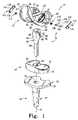
- FIG. 1is an exploded, perspective view of a hinged knee prosthesis
- FIG. 2is a part-sectional side view of the hinged knee prosthesis of FIG. 1 showing, in phantom, motion of a femoral component of the hinged knee prosthesis;
- FIG. 3is a part-sectional side view of another hinged knee prosthesis
- FIG. 4is an exploded, perspective view of yet another hinged knee prosthesis
- FIG. 5is a part-sectional side view of the hinged prosthesis of FIG. 4 ;
- FIG. 6is an exploded, perspective view of another hinged knee prosthesis
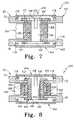
- FIG. 7is a top sectional view of the hinged knee prosthesis of FIGS. 4 and 5 including a hinge pin assembly coupling a femoral component and a bearing component of the hinged knee prosthesis together;
- FIG. 8is a top sectional view of another hinged knee prosthesis including an alternative hinge pin assembly.
- FIG. 9is a diagrammatic view of a femoral component having a slot formed within a side wall of the femoral component which follows the curvature of an outer condylar surface of the femoral component.
- a hinged prosthetic deviceillustratively, a hinged knee prosthesis 10 , includes a femoral component 12 , a hinge assembly 14 , a bearing component 16 , and a tibial component or tray 18 .
- the hinge assembly 14is pivotably coupled to the femoral component 12 and is received within the tibial tray 18 in order to stabilize relative movement between the femoral component 12 and the bearing component 16 .
- the hinge assembly 14is received through elongated guide slots 20 of the femoral component 12 in order to guide the movement of the femoral component 12 relative to both the bearing component 16 and the tibial component 18 .
- Such movement of the femoral component 12 as guided by the slots 20 and the hinge assembly 14provides for a more even distribution of weight loads from the femoral component 12 across the bearing component 16 and to the tibial tray 18 during movement of the knee prosthesis 10 between flexed and extended positions.
- the tibial tray 18includes a platform 30 from which a stem 32 extends.
- the tibial stem 32is configured to be implanted into a prepared end of a patient's tibia (not shown).
- An elongated cylindrical cavity 34 of the tibial tray 18is formed through the platform 30 and within the stem 32 of the tibial tray 18 .
- the illustrative bearing component 16includes a generally flat bottom surface 36 configured to rest upon the generally flat top surface 38 of the platform 30 .
- the bearing component 16is rotatable relative to the tibial tray 18 about an axis 40 running through the elongated cylindrical cavity 34 of the tibial tray 18 .
- the bearing component 16further includes a lateral bearing surface 42 and a medial bearing surface 44 .
- the bearing surfaces 42 , 44are configured to articulate with a lateral condyle surface 52 and a medial condyle surface 54 , respectively, of the femoral component 12 , as discussed below.
- the bearing component 16further defines an aperture or slot 60 extending through the body of the bearing component 16 .
- the slot 60is positioned between the bearing surfaces 42 , 44 of the bearing component 16 and is configured to be aligned with the cylindrical cavity 34 of the tibial tray 18 .
- the slot 60slidably receives a portion of the hinge assembly 14 therethrough, as is discussed in greater detail below.
- the hinge assembly 14 and the slot 60are shaped to prevent axial rotation of the hinge assembly 14 relative to the bearing component 16 about the axis 40 shown in FIG. 1 .
- the hinge assembly 14 and the bearing component 16rotate together relative to the tibial tray 18 about the axis 40 .
- the hinge assembly 14is coupled to the femoral component 12 such that the femoral component 12 is also able to rotate with the hinge assembly 14 and the bearing component 16 about the axis 40 .
- the femoral component 12is configured to be implanted into a prepared end of the patient's femur (not shown), and is configured to emulate the configuration of the patient's natural femoral condyles (not shown).
- the femoral component 12includes a body 56 having a pair of spaced-apart lateral and medial condylar members 58 which each include the respective lateral condyle surface 52 and the medial condyle surface 54 formed to articulate with the bearing 16 .
- outer, curved surfaces 52 , 54each include curved segments S 1 , S 2 , and S 3 each having a radii R 1 , R 2 , and R 3 respectively, as shown diagrammatically with reference to a similar femoral component 312 in FIG. 9 , for example.
- the segmentsform a smooth surface in which the radii at the interface between the adjacent surface segments having common tangents.
- the lateral condyle surface 52 and the medial condyle surface 54are configured (e.g., curved) in a manner which mimics the condyles of a natural femur.
- An anterior patellar flange 57 of the femoral component 12is integral with and interconnects anterior portions of the condyle members 58 .
- a cam box 62 of the femoral component 12is positioned between and coupled to the condylar members 58 .
- the cam box 62includes first (or lateral) and second (or medial) side walls 70 , 72 which are coupled to and project from the body 56 of the femoral component 12 .
- each of the first and second side walls 70 , 72is formed integrally with the corresponding lateral and medial condylar member 58 .
- Each side wall 70 , 72defines a top wall 74 of the cam box 62 and an opening 76 of the cam box 62 is provided between the side walls 70 , 72 .
- each elongated slot or track 20is formed in each side wall 70 , 72 .
- each elongated slot 20is angled to define an imaginary line extending from an anterior/inferior front end of each slot 20 toward a posterior/superior back end of each slot 20 .
- the longitudinal axis of each slot 20is each angled upwardly such that a posterior end of each slot 20 is positioned higher than an anterior end of each slot 20 .
- the slots 20 of the femoral component 12are generally straight, rather than curved, for example. However, it is within the scope of this disclosure for the slots 20 to be curved as well.
- slots 20are shown to have a particular length and width relative to other features of the femoral component 12 , it is within the scope of this disclosure to provide a slot having any suitable length and width.
- a portion of the hinge assembly 14is coupled to the cam box 62 and slides along the tracks 20 of the cam box 62 .
- each of the femoral component 12includes a rod support (not shown) coupled to the body 56 in a position generally between the condylar members 58 .
- the rod supportis formed to receive a stabilizing rod (not shown) for implantation into the prepared femur of a patient undergoing a total knee replacement surgery, for example.
- each of the femoral components shown and described hereinincludes such a rod support and/or stabilizing rod in order to couple the femoral component to a patient's femur.
- the components of the knee prosthesis 10 that engage the natural bonesuch as the femoral component 12 and the tibial tray 18 may be constructed from a biocompatible metal, such as titanium or cobalt chrome alloy for example.
- the bone engaging surfaces of these componentsmay be textured to facilitate cementing the component to the bone. Such surfaces may also be porous coated to promote bone ingrowth for permanent fixation.
- the bearing component 16may be constructed from a material that allows for smooth articulation and rotation between the bearing component 16 and the adjacent femoral and tibial components 12 , 18 .
- One such materialis ultra high molecular weight polyethylene (UHMWPE).
- UHMWPEultra high molecular weight polyethylene
- the bearing 16may be made from other suitable polymers as well.
- the hinge assembly 14 of the prosthesis 10includes a metal piston 80 having a head 82 and a shaft 84 coupled to the head 82 .
- the head 82includes two side walls, illustratively, a lateral side wall 86 and a medial side wall 88 , a top wall 90 , a posterior wall 92 , and an anterior wall 94 .
- a curved surface 96is defined between the anterior wall 94 and the top wall 90 .
- a bore 98is formed through the head 82 of the piston 80 and extends from the lateral side wall 86 to the medial side wall 88 .
- the bore 98extends in a medial/lateral direction through the head 82 of the piston 80
- the shaft 84generally defines a circular cylinder and is received through the aperture 60 of the bearing component 16 and into the elongated cylindrical cavity 34 of the tibial tray 18 .
- the piston 80may be made from any suitable metal such as titanium or cobalt chrome alloy, for example.
- the piston 80may be made from any suitable polymer as well.
- the hinge assembly 14further includes a hinge pin 100 to be received through the bore 98 formed in the head 82 of the piston 80 .
- the hinge pin 100is also received through the first and second slots 20 formed within the side walls 70 , 72 of the femoral component 12 in order to couple the piston 80 to the femoral component 12 , as is discussed in greater detail below.
- the illustrative hinge pin 100includes a head or cap 102 and a body 104 coupled to the cap 102 which generally defines a circular cylinder. Opposite the cap 102 , the body 104 of the pin 100 includes a slot 106 formed therein and a foot or outer rim 108 of the pin 100 is coupled to the body 104 .
- the hinge pin 100is metal; however, it is within the scope of this disclosure for the hinge pin 100 to be made from other suitable materials such as polymers, for example.
- First and second bearings 110 , 112 of the hinge assembly 14are coupled to the outer ends (i.e., the cap 102 and the outer rim 108 ) of the hinge pin 100 .
- the bearings 110 , 112are made from a polymer and illustratively operate to provide a bearing surface between the metal hinge pin 100 and the metal femoral component 12 .
- the bearings 110 , 112reduce friction and wear between the hinge pin 100 and side walls 70 , 72 of the cam box 62 which define the slots 20 within which the hinge pin 100 translates.
- the prosthesis 10further includes slot covers 114 , as shown in FIG. 1 , which snap into the slots 20 of the femoral component 12 and shield the slots 20 from the patient's surrounding bone (not shown).
- Each slot cover 114includes a generally oval-shaped body 116 and two flanges 118 coupled to opposite ends of each body 116 .
- the flanges 118are curved or are generally “C-shaped” and are provided to snap into the respective slot 20 in order to couple the slot cover 114 to the femoral component 12 .
- the slot covers 114operate to cover or shield the open slots 20 from the patient's surrounding natural bone in order to help prevent the patient's bone from growing into the slots 20 .
- the slot covers 114operate to prevent or reduce bone ingrowth into the slots 20 .
- the stem 84 of the piston 80 of the hinge assembly 14is received through the aperture 60 of the bearing component 16 and into the elongated cylindrical cavity 34 of the tibial tray 18 .
- the head 82 of the piston 80is positioned within the cam box 62 between the side walls 70 , 72 of the femoral component 12 such that the bore 98 of the head 82 is aligned with the slot 20 formed in each side wall 70 , 72 of the femoral component 12 .
- the hinge pin 100is received through the slot 20 formed in the lateral wall 70 of the femoral component 12 , the bore 98 of the head 82 , and the slot 20 formed in the medial wall 72 of the femoral component 12 in order to couple the piston 80 of the hinge assembly 14 with the femoral component 12 .
- the bearings 110 , 112are positioned between the pin 100 and the side walls 70 , 72 defining elongated slot or guide track 20 .
- the pin 100 of the hinge assembly 14translates along the slots 20 relative to the femoral component 12 .
- the hinged knee prosthesis 10is shown in a flexed position such that the piston 80 has moved downwardly relative to the bearing component 16 and the tibial tray 18 .
- the hinge pin 100 of the hinge assembly 14has translated along the slots 20 formed in the side walls 70 , 72 of the femoral component 12 to be positioned at the upper, posterior end of each slot 20 .
- the piston 80is able to move up and down as necessary within the cylindrical cavity 34 of the tibial tray 18 as the prosthesis 10 moves between the extended position and various flexed positions. As the prosthesis 10 moves between extended and flexed positions, the elongated slots 20 of the femoral component 12 guide the movement of the femoral component 12 and the hinge assembly 14 relative to the bearing component 16 .
- the hinge pin 100 of the hinge assembly 14is urged to translate along the elongated slots 20 formed in the cam box 62 of the femoral component 12 .
- the piston 80 of the hinge assembly 14moves up and down relative to the tibial tray 18 and the bearing component 16 as the femoral component 12 flexes and extends.
- the slots 20allow the femoral component 12 to articulate on the bearing component 16 such that the bearing component 16 remains relatively stationary and does not move significantly in the anterior or posterior directions during such articulation. In other words, an axis of rotation of the femoral component 12 is not fixed.
- the slots 20 of the femoral component 12provide a variable axis of rotation of the femoral component 12 about the hinge pin 100 which translates along the slots 20 .
- Such rotational and sliding movement of the femoral component 12 on the bearing component 16functions to mimic the operation and movement of the patient's natural anatomy. Because the femoral component 12 is able to slide anteriorly and posteriorly on the bearing component 16 to maintain articulating between the condylar surfaces 52 , 54 of the femoral component 12 and the bearing surfaces 42 , 44 of the bearing component 16 , any anterior/posterior movement of the bearing component 16 relative to the tibial tray 18 is reduced.
- such rotational and sliding movement of the femoral component 12 relative to the bearing component 16 about a variable or moving axis of rotationoperates to evenly distribute weight loads across the prosthesis 10 as the prosthesis 10 moves between flexed and extended positions. Weight or stress loads are evenly transferred or distributed from the femoral component 12 across the bearing component 16 during the full range of motion or movement of the prosthesis 10 between flexed and extended positions.
- the prosthesis 10is capable of a flexion angle of approximately 145 degrees.
- the bearing component 16 of the knee prosthesis 10operates to transfer many or all of the applied loads from the femoral component 12 to the tibial tray 18 .
- the hinge assembly 14mainly operates to stabilize the knee prosthesis 10 and guide the motion of the knee prosthesis 10 through flexed and extended positions.
- the hinge assembly 14may operate to transfer some load across the components as well.
- the weight loads carried across the bearing component 16may be evenly distributed throughout the entire range of motion.
- the hinged knee prosthesis 210includes a femoral component 212 , a bearing component 216 , a tibial tray component 218 and a hinge assembly 214 .
- the femoral component 212 of the prosthesis 210is similar to the femoral component 12 of the prosthesis 10 .
- like reference numeralshave been used to denote like components.
- the femoral component 212includes the elongated slots 20 formed within the side walls 70 , 72 of the femoral component 212 .
- the bearing component 216 of the prosthesis 210includes a platform 220 and a stem 222 coupled to a bottom surface 236 of the platform 220 and configured to extend downwardly therefrom.
- An upper surface of the platform 220illustratively defines the bearing surfaces 42 , 44 of the bearing component 216 .
- a generally cylindrical bore 260is formed through the platform 220 and the stem 222 of the bearing component 216 and receives a portion of the hinge assembly 214 therethrough as is discussed in greater detail below.
- the tibia tray 218 of the prosthesis 210includes a platform 230 from which a stem 232 extends.
- the tibial stem 232is configured to be implanted into a prepared end of a patient's tibia (not shown).
- the a generally flat bottom surface 236 of the illustrative bearing component 216is configured to rest upon the generally flat top surface 238 of the platform 230 .
- the stem 222 of the bearing component 216is received within an elongated cylindrical cavity 234 formed in the tibial tray 218 .
- the bearing component 216is rotatable relative to the tibial tray 218 about the axis 40 running through the cavity 234 of the tibial tray 218 .
- the hinge assembly 214 of the prosthesis 210is pivotably coupled to the femoral component 212 and is received through the bearing component 216 and within the tibial tray 218 in order to stabilize relative movement between the femoral component 212 and the bearing component 216 .
- the femoral component 212 of the illustrative prosthesis 210includes guide slots 20 to guide and limit the range of motion of the femoral component 212 of the prosthesis 210 while also providing a variable axis of rotation through the hinge pin 100 of the hinge assembly 214 .
- this variable axis of rotationpermits the femoral component 212 to slide and rotate on the bearing component 216 which aides in evenly transferring weight loads from the femoral component 212 across the bearing component 216 and to the tibial tray 218 as the prosthesis moves between flexed and extended positions.
- the hinge assembly 214includes a metal piston 280 having a head 282 and a shaft 284 coupled to the head 282 .
- the head 282includes two side walls 286 , an angled top wall 290 , an angled bottom wall 292 connected to the angled top wall 290 at a posterior curved portion 294 .
- a bore 298 extending in a medical/lateral directionis formed through the head 282 of the piston 280 to extend between the side walls 286 .
- the shaft 284generally defines a circular cylinder and is received through the cylindrical bore 260 of the bearing component 216 and into the cylindrical cavity 234 of the tibial tray 218 .
- the hinge assembly 114further includes the hinge pin 100 to be received through the bore 298 formed in the head 282 of the piston 280 . As shown in FIG. 3 , for example, the hinge pin 100 is also received through the slots 20 formed within the side walls 70 , 72 of the femoral component 212 in order to couple the piston 280 of the hinge assembly 214 to the femoral component 212 , as is discussed in greater detail below.
- the hinge pin 100 of the hinge assembly 114is the same as or similar to the hinge pin 100 of the hinge assembly 14 . As such, like reference numerals have been used to denote like components.
- Bushings 110 , 112 of the hinge assembly 214may be coupled to the outer ends of the hinge pin 100 .
- slot covers 114may also be provided to snap into the slots 20 and shield the open portions of the each slot 20 from the surrounding bone.
- the stem 282 of the piston 280 of the hinge assembly 214is received through the bore 260 of the bearing component 216 and into the elongated cylindrical cavity 234 of the tibial tray 218 .
- the head 282 of the piston 280is positioned within the cam box 62 and between the side walls 70 , 72 of the femoral component 212 such that the bore 298 of the head 282 is aligned with the slot 20 formed in each side wall 70 , 72 of the femoral component 212 .
- the hinge pin 100is received through the slot 20 formed in the lateral wall 70 of the femoral component 212 , the bore 298 of the head 282 , and the slot 20 formed in the medial wall 72 of the femoral component 212 in order to couple the piston 280 of the hinge assembly 214 with the femoral component 212 .
- the hinge assembly 214further includes a liner or sleeve 250 coupled to a distal end 252 of the piston 280 .
- the distal end 252 of the stem 284 of the piston 280is knurled, as shown in FIG. 3 , in order to maintain the liner 250 on the end 252 of the stem 284 and reduce relative movement between the piston 280 and the liner 250 .
- the sleeve 250is generally cylindrical in shape and defines a central bore formed to receive the distal end 252 of the stem 284 therein. The liner 250 and the distal end 252 of the piston 280 are received within the cylindrical cavity 234 of the tibial tray 218 .
- the piston 280is metal and moves upwardly and downwardly within the both the cylindrical bore 260 of the bearing component 216 and the cylindrical cavity 234 of the tibial tray 218 .
- the illustrative liner 250is made from a polymer, such as UHMWPE, for example, and therefore operates to prevent metal-on-metal wear between the stem 284 of the piston 280 and the metal tray 218 .
- the liner 250is coupled to the distal end 252 of the stem 284 of the piston 280 .
- the liner 250moves upwardly and downwardly with the piston 280 as the prosthesis 210 is moved between flexed and extended positions, as is discussed above in regards to the prosthesis 10 .
- the liner 250is coupled to the stem 284 of the piston 280 to move with the piston 280 relative to both the tibial tray 218 and the bearing component 216 .
- the liner 250also operates to limit the upward travel of the piston 280 in order to further constrain the prosthesis 210 .
- an upper surface 254 of the liner 250may contact a lower surface 256 of the stem 222 of the bearing component 216 in order to prevent the liner 250 and the piston 280 from continuing to move upwardly relative to the tray 218 and the bearing component 216 .
- Limiting the upward movement of the piston 280further constrains or limits the amount of extension of the prosthesis 210 .
- liner 250 as well as the stem 222 of the bearing component 216may be sized to increase or decrease amount of upwardly and downwardly travel of the piston 280 .
- the position of the liner 250 on the stem 222may also be changed in order to adjust the amount of travel of the piston 280 .
- the knee prosthesis 310includes a femoral component 312 , a bearing component 316 , a tibial tray 218 , and a hinge assembly 314 .
- the femoral component 312is similar to the femoral components 12 , 212 described above. As such, like reference numerals are used to denote like features.
- the bearing component 316 of the prosthesis 310is a varus-valgus constrained (VCC) mobile bearing component which provides posterior stabilization to the knee prosthesis 310 in order to reduce the possibility of anterior subluxation or dislocation of the femur.
- VCCvarus-valgus constrained
- the bearing component of a posterior stabilized knee prosthesisincludes a spine, such as the spine 350 between the articular condyles 42 , 44 of the bearing component 316 .
- the posterior surface of the spineinteracts with a cam on the posterior aspect of the femoral component 312 to provide posterior stability to the prosthesis 310 .
- a varus/valgus constrained (VVC) implantmay be used.
- the varus/valgus constraintoperates to prevent or resist liftoff.
- the varus/valgus constraintis provided by raising and reinforcing the tibial spine 350 and by using a tighter fit between the side walls of the tibial 350 spine and the corresponding side walls 70 , 72 of the femoral cam box 62 .
- the width of the cam box 62 compared to the width of the spine 350may be carefully selected to allow only a small degree of condylar liftoff, thus providing varus/valgus stability to the knee without inducing excessive forces to the spine and to the bone/implant fixation interfaces.
- the bearing component 316includes a platform 319 defining the lateral bearing surface 42 and the medial bearing surface 44 .
- the bearing component 316further includes a stem 322 coupled to a bottom surface 336 of the platform 319 of the bearing component 316 and positioned to extend downwardly therefrom.
- the illustrative stem 322is generally conical in shape and is formed to be received within the elongated cylindrical cavity 234 of the tibial tray component 218 such that the bottom surface 336 of the platform 319 of the bearing component 316 is adjacent to and engaged with the top surface of the platform 230 of the tray 218 .
- the bearing component 316further includes the spine 350 coupled to the platform 319 of the bearing component 316 and positioned to extend upwardly therefrom.
- the spine 350is positioned between the lateral and medial condyle surfaces 42 , 44 of the bearing component 316 .
- the spine 350includes a generally vertical posterior surface 352 , medial and lateral surfaces 386 , 388 , an angled anterior surface 390 , and an angled superior or top surface 392 .
- the posterior surface 352 of the spineoperates as a cam follower against a cam surface 66 of the femoral component 312 , described in greater detail below.
- the spine 350includes a bore 398 extending between the medial and lateral surfaces 386 , 388 of the spine 350 .
- the bore 398extends in a medical/lateral direction through the spine 350 .
- the hinge assembly 314 of the prosthesis 310operates to mechanically couple or link the spine 350 of the bearing component 316 with the femoral component 312 .
- the femoral component 312 of the knee prosthesis 310is similar to the femoral components 12 , 212 described above. As such, like reference numerals are used to denote like components and features. Additionally, the cam box 62 of the femoral component 312 includes an anterior cam face 64 and a posterior cam face 66 which interacts with corresponding cam surfaces of the spine 350 as the prosthesis 310 moves between flexed and extended positions. For example, the posterior surface 352 of the spine 350 may interact with the posterior cam surface 66 of the cam box 62 when the prosthesis 310 is in the flexed position. Similarly, surfaces 390 , 392 of the spine 350 may interact with the anterior cam surface 64 when the prosthesis 310 in an extended position.
- the femoral component 312 of the knee prosthesis 310includes elongated, curved slots 320 formed in each side wall 70 , 72 of the cam box 62 of the femoral component 312 .
- the slots 20 of the femoral components 12 , 212are generally straight
- the slots 320 of the femoral component 312 of the knee prosthesis 310are curved, as shown in FIGS. 4 and 5 .
- each condylar member 58defines an outer, curved surface 52 , 54 which each includes curved segments S 1 , S 2 , and S 3 each having a radii R 1 , R 2 , and R 3 respectively.
- the segments S 1 , S 2 , and S 3form a smooth surface such that the radii R 1 , R 2 , and R 3 at the interface between the adjacent surface segments S 1 , S 2 , and S 3 have common tangents.
- each slot 320 of the femoral component 312follows the curvature of the condylar members 58 such that each slot 320 similarly includes curved segments each having a radii which corresponds to the radii R 1 , R 2 , R 3 of the condylar members 58 .
- the curvature of each slot 320 formed in the cam box 62 of the femoral component 312follows the curvature of the condylar members 58 .
- the hinge assembly 314 of the knee prosthesis 310includes the hinge pin 100 , bushings 110 , 112 and slot covers 414 discussed above in regards to the hinge assemblies 14 and 214 .
- the slot covers 414include a curved body 416 corresponding to the curved shape of the slots 320 .
- the hinge assembly 314 of the prosthesis 310does not include a piston component such as the pistons 80 and 280 described above. However, the hinge assembly 314 of the prosthesis 310 operates to mechanically link the femoral component 312 with the bearing component 316 in order to constrain the movement of the femoral component 312 relative to the bearing component 316 .
- the curved slots 320 of the femoral component 312operate to guide the movement of the femoral component 312 relative to the bearing component 316 to provide a variable axis of rotation of the femoral component to allow the weight of the femur to be evenly distributed throughout the range of motion of the knee prosthesis 310 .
- the tibial tray component 218is secured to a prepared tibia (not shown) of a patient and the bearing component 316 is received within the elongated conical bore 34 of the tibial tray component 218 .
- the cone or stem 322 of the bearing component 316is received within the elongated conical bore 234 of the tibial tray component 218 such that the bottom surface 336 of the platform 319 of the bearing component 316 is adjacent to and engages the top surface 38 of the platform 230 of the tibial tray component 218 .
- the bearing component 316operates as a rotational platform of the knee prosthesis 310 such that the bearing component 316 is able to rotate about the axis 40 extending through the stem 232 of the tibial tray component 218 relative to the tibial tray component 218 .
- the rotational motion of the illustrative bearing component 316 relative to the tray component 218is generally not hindered or restricted. It is, of course, within the scope of this disclosure, however, to restrict the rotational motion of the bearing component relative to the tibial tray component 218 and/or to provide a fixed bearing component which is generally not able to rotate relative to the tibial tray component.
- rotationally fixed or restricted bearing componentsmay be provided for any of the knee prostheses disclosed herein.
- the spine 350 of the bearing component 316is received within the cam box 62 of the femoral component 312 such that the medial side 386 of the spine 350 is adjacent the medial side wall 70 of the cam box 62 and the lateral side 388 of the spine 350 is adjacent the lateral side wall 72 of the cam box 62 .
- the hinge pin 100 of the hinge assembly 314is received through the side walls 70 , 72 of the cam box 62 and the bore 398 of the spine 350 in order to pivotably couple the bearing component 316 and the femoral component 312 to one another.
- the hinge pin 100is received through the elongated, curved slot 320 formed in each side wall 70 , 72 of the cam box 62 and is able to translate along the slots 320 in a path defined by the curvature of the slots 320 .
- the curvature of the slots 320is the same as or similar to the curvature of the condylar members 58 of the femoral component 312 . As such, movement of the femoral component 312 relative to the bearing component 316 is restricted to the motion defined by the slots 320 .
- the movement of the femoral component 312 relative to the bearing component 316is limited at least in part by the shape and size of the slots 320 .
- the hinge pin 100 coupling the femoral component 312 to the bearing component 316effectively restrains the motion of the femoral component 312 to the size and shape of the slots 320 .
- the illustrative slots 320are shown to have a particular length, width, and curvature relative to the other features of the femoral component 312 , it is within the scope of this disclosure to provide a slot having any suitable length, width, and curvature.
- certain components of the knee prosthesis 310may be used as a typical varus/valgus constrained knee prosthesis without the need to hinge the femoral component 312 to the bearing component 316 .
- the knee prosthesis 310is able to convert from a VCC knee prosthesis to a hinged, VCC knee prosthesis.
- an initial or first total knee replacement surgerymay use the tray component 218 and slotted femoral component 312 shown in FIGS. 4 and 5 while implementing either the bearing component 316 or another bearing component (not shown) similar in structure to the bearing component 316 but without the bore 398 formed through the spine 350 of the bearing component 316 .
- the surgeonmay choose to not utilize the hinge assembly 314 to link the femoral component 312 and the bearing component 316 together.
- Such a knee prosthesismay remain in place within the patient until the knee prosthesis becomes unstable.
- the surgeonmay perform a revision knee replacement surgery in order to improve the stability of the knee prosthesis by adding additional constraints.
- One such additional constraintmay be the hinge assembly 314 , for example.
- the surgeonmay simply remove the alternative bearing component for use with the non-hinged knee prosthesis and replace it with another bearing component for use with a hinged knee prosthesis, such as the bearing component 316 , which is suitable to receive a hinge assembly, such as the hinge assembly 314 , for example.
- the surgeonmay install the hinge assembly 314 in order to couple the bearing component 316 with the femoral component 312 to link the two components 312 , 316 together and further constrain the motion of the femoral component 312 to that defined by the slots 320 of the femoral component 312 .
- the surgeonmay simply add the hinge assembly 114 to the components to further constrain the relative motion of the components.
- the knee prosthesis 410is a VVC knee prosthesis including the hinge assembly 314 .
- the knee prosthesis 410includes a bearing component 417 having a spine 450 shaped differently than the spine 350 disclosed above with respect to the knee prosthesis 310 .
- the spine 450 of the bearing component 417includes a generally vertical anterior surface 490 and a top or superior surface 492 which is angled from horizontal to a lesser degree than the top surface 392 of the spine 350 .
- the generally vertical anterior surface 452 of the spine 450generally operates to further prevent over-extension of the femoral component 312 relative to the bearing component 417 .
- the spine 450also includes the bore 398 formed therethrough and the hinge pin 100 of the hinge assembly 314 is received through the bore 398 and the slots 320 of the femoral component 312 in order to couple the femoral and bearing components 312 , 417 together.
- the operation of the knee prosthesis 410is similar to, if not the same as, the operation of the knee prosthesis 310 in that the motion of the femoral component 312 is limited to the size and shape of the slots 320 formed in the stabilizing box 62 of the femoral component 312 .
- FIG. 7a part-sectional, part-fragmentary view of the knee prosthesis 310 of FIGS. 4 and 5 is provided.
- the hinge pin 100 of the hinge assembly 314is received through the bore 398 formed in the spine 350 of the bearing component 316 as well as the slots 320 formed in the side walls 70 , 72 of the cam box 62 of the femoral component 312 .
- the hinge pin 100includes the cap 102 , the body 104 , and the foot 108 .
- the slot 106is formed in the body 104 of the pin 100 in order to allow the foot end of the pin 100 to be compressed or pinched together.
- both the hinge pin 100 and the femoral components 312are made from metal.
- plastic or polymer bearings 110 , 112are coupled to the respective cap 102 and foot 108 of the pin 100 and are received within the slots 320 of the femoral component 320 to prevent metal-on-metal wear between the pin 100 and the slots 320 .
- the bearings 110 , 112carry the hinge pin 100 and translate within the slots 320 as the femoral component 312 moves relative to the bearing component 316 .
- the knee prosthesis 310(as well as the knee prostheses 10 , 210 , and 410 ) includes slot covers 414 which are coupled to the femoral component 312 in order to cover the slots 320 .
- the slot covers 414operate to cover the slots 320 in order to prevent or reduce any bone ingrowth of the patient's natural femur into the open slots 320 .
- the illustrative slot covers 414include a curved body 416 and flexible flanges 118 which may be snapped into the slots 320 , as shown in FIG. 7 .
- the slot covers 414 provided to cover the elongated, curved slots 320 of the femoral component 312are similarly curved while the slot covers 114 provided to cover the elongated, generally straight slots 20 of the femoral components 12 and 212 are similarly straight.
- the shape of the slot covers of each prosthesiscorrespond to the shape of the slots formed in the femoral component of each prosthesis.
- FIG. 8a part-sectional, part-fragmentary view of another knee prosthesis 510 is provided.
- the knee prosthesis 510is similar to the knee prosthesis 310 ; as such, like reference numerals have been used to denote like components.
- a hinge assembly 514 of the knee prosthesis 510includes polymer bearings 610 , 612 similar to the polymer bearings 110 , 112 shown in FIG. 7 .
- the polymer bearings 610 , 612each include sleeve portions 616 such that the body 104 of the pin 100 is received within and surrounded by the sleeve portions 616 of the bearings 610 , 612 .
- a metal bushing 520 of the hinge assembly 514is provided between the bearing component 316 and the bearings 610 , 612 in order to prevent wear between the femoral component 312 and the hinge assembly 514 . Further, such bushings and bearings may prevent or reduce the components from locking up and allow the hinge pin 100 , the bearing component 316 , and the femoral component 312 to move smoothly and easily relative to one another.
- the hinge assembly 114 shown in FIG. 7 or the hinge assembly 514 shown in FIG. 8may be used with any of the knee prostheses disclosed herein.
- a hinged prosthetic joint for accommodating articulation between a first bone and a second bonemay include a first component configured to be attached to the first bone and a second component configured to be attached to the second bone.
- the first componentmay include a body and an elongated slot formed in the body.
- a bearing component of the prosthetic jointis positioned between the first and second components and a hinge assembly, such as the hinge assemblies 14 , 114 , 214 , 314 described above, may include a hinge pin received within the slot of the first component.
Landscapes
- Health & Medical Sciences (AREA)
- Orthopedic Medicine & Surgery (AREA)
- Physical Education & Sports Medicine (AREA)
- Cardiology (AREA)
- Oral & Maxillofacial Surgery (AREA)
- Transplantation (AREA)
- Engineering & Computer Science (AREA)
- Biomedical Technology (AREA)
- Heart & Thoracic Surgery (AREA)
- Vascular Medicine (AREA)
- Life Sciences & Earth Sciences (AREA)
- Animal Behavior & Ethology (AREA)
- General Health & Medical Sciences (AREA)
- Public Health (AREA)
- Veterinary Medicine (AREA)
- Prostheses (AREA)
- Materials For Medical Uses (AREA)
Abstract
Description
Claims (21)
Priority Applications (6)
| Application Number | Priority Date | Filing Date | Title |
|---|---|---|---|
| US11/428,066US7658767B2 (en) | 2006-06-30 | 2006-06-30 | Hinged orthopaedic prosthesis |
| AT07252632TATE529071T1 (en) | 2006-06-30 | 2007-06-28 | ORTHOPEDIC PROSTHESIS WITH JOINT |
| AU2007203005AAU2007203005B2 (en) | 2006-06-30 | 2007-06-28 | Hinged orthopaedic prosthesis |
| EP07252632AEP1872747B1 (en) | 2006-06-30 | 2007-06-28 | Hinged orthopaedic prosthesis |
| CN2007101385088ACN101095631B (en) | 2006-06-30 | 2007-06-29 | Hinged orthopaedic prosthesis |
| JP2007172619AJP5538668B2 (en) | 2006-06-30 | 2007-06-29 | Hinged orthopedic joint |
Applications Claiming Priority (1)
| Application Number | Priority Date | Filing Date | Title |
|---|---|---|---|
| US11/428,066US7658767B2 (en) | 2006-06-30 | 2006-06-30 | Hinged orthopaedic prosthesis |
Publications (2)
| Publication Number | Publication Date |
|---|---|
| US20080004708A1 US20080004708A1 (en) | 2008-01-03 |
| US7658767B2true US7658767B2 (en) | 2010-02-09 |
Family
ID=38529460
Family Applications (1)
| Application Number | Title | Priority Date | Filing Date |
|---|---|---|---|
| US11/428,066Active2027-03-10US7658767B2 (en) | 2006-06-30 | 2006-06-30 | Hinged orthopaedic prosthesis |
Country Status (6)
| Country | Link |
|---|---|
| US (1) | US7658767B2 (en) |
| EP (1) | EP1872747B1 (en) |
| JP (1) | JP5538668B2 (en) |
| CN (1) | CN101095631B (en) |
| AT (1) | ATE529071T1 (en) |
| AU (1) | AU2007203005B2 (en) |
Cited By (48)
| Publication number | Priority date | Publication date | Assignee | Title |
|---|---|---|---|---|
| US20070135926A1 (en)* | 2005-12-14 | 2007-06-14 | Peter Walker | Surface guided knee replacement |
| US20090043395A1 (en)* | 2005-07-14 | 2009-02-12 | Takao Hotokebuchi | Artificial knee joint |
| US20090088860A1 (en)* | 2007-09-30 | 2009-04-02 | Romeis Kristen L | Hinged orthopaedic prosthesis |
| US20090125116A1 (en)* | 2001-12-21 | 2009-05-14 | Smith & Nephew, Inc. | Hinged joint system |
| US20090143866A1 (en)* | 2007-11-30 | 2009-06-04 | Howmedica Osteonics Corp. | Knee prosthesis with four degrees of freedom |
| US20090326666A1 (en)* | 2008-06-30 | 2009-12-31 | Wyss Joseph G | Posterior stabilized orthopaedic prosthesis |
| US20100016979A1 (en)* | 2008-07-16 | 2010-01-21 | Depuy Products, Inc. | Knee prostheses with enhanced kinematics |
| US20100131070A1 (en)* | 2006-06-30 | 2010-05-27 | Smith & Nephew, Inc. | Anatomical motion hinged prosthesis |
| US20100234962A1 (en)* | 2001-01-29 | 2010-09-16 | Zimmer Technology, Inc. | Constrained prosthetic knee with rotating bearing |
| US20100286788A1 (en)* | 2009-05-07 | 2010-11-11 | Richard David Komistek | Anterior stabilized knee implant |
| US20110040387A1 (en)* | 2009-08-11 | 2011-02-17 | IMDS, Inc. | Systems and methods for mobile bearing prosthetic knee |
| US20110202139A1 (en)* | 2010-02-18 | 2011-08-18 | Biomet Manufacturing Corp. | Prosthetic device with damper |
| US8029574B2 (en) | 2006-11-07 | 2011-10-04 | Biomedflex Llc | Prosthetic knee joint |
| US8070823B2 (en) | 2006-11-07 | 2011-12-06 | Biomedflex Llc | Prosthetic ball-and-socket joint |
| US8187335B2 (en) | 2008-06-30 | 2012-05-29 | Depuy Products, Inc. | Posterior stabilized orthopaedic knee prosthesis having controlled condylar curvature |
| US8192498B2 (en) | 2008-06-30 | 2012-06-05 | Depuy Products, Inc. | Posterior cructiate-retaining orthopaedic knee prosthesis having controlled condylar curvature |
| WO2012093961A1 (en)* | 2011-01-05 | 2012-07-12 | Milux Holding S.A. | Knee joint device |
| US8236061B2 (en) | 2008-06-30 | 2012-08-07 | Depuy Products, Inc. | Orthopaedic knee prosthesis having controlled condylar curvature |
| US8308812B2 (en) | 2006-11-07 | 2012-11-13 | Biomedflex, Llc | Prosthetic joint assembly and joint member therefor |
| US8512413B2 (en) | 2006-11-07 | 2013-08-20 | Biomedflex, Llc | Prosthetic knee joint |
| USRE44476E1 (en) | 2001-01-29 | 2013-09-03 | Zimmer, Inc. | Constrained prosthetic knee with rotating bearing |
| US8628579B2 (en) | 2009-08-11 | 2014-01-14 | Imds Corporation | Systems and methods for prosthetic knee |
| US8636807B2 (en) | 2006-03-21 | 2014-01-28 | Depuy (Ireland) | Moment induced total arthroplasty prosthetic |
| US8747479B2 (en) | 2011-04-26 | 2014-06-10 | Michael A. McShane | Tibial component |
| US8828086B2 (en) | 2008-06-30 | 2014-09-09 | Depuy (Ireland) | Orthopaedic femoral component having controlled condylar curvature |
| US8845744B2 (en)* | 2012-01-09 | 2014-09-30 | Biomet Manufacturing, Llc | Ulnar head implant |
| US8998997B2 (en) | 2009-08-11 | 2015-04-07 | Michael D. Ries | Implantable mobile bearing prosthetics |
| US9005307B2 (en) | 2006-11-07 | 2015-04-14 | Biomedflex, Llc | Prosthetic ball-and-socket joint |
| US9005306B2 (en) | 2006-11-07 | 2015-04-14 | Biomedflex, Llc | Medical Implants With Compliant Wear-Resistant Surfaces |
| US9095453B2 (en) | 2009-08-11 | 2015-08-04 | Michael D. Ries | Position adjustable trial systems for prosthetic implants |
| US9119723B2 (en) | 2008-06-30 | 2015-09-01 | Depuy (Ireland) | Posterior stabilized orthopaedic prosthesis assembly |
| US9168145B2 (en) | 2008-06-30 | 2015-10-27 | Depuy (Ireland) | Posterior stabilized orthopaedic knee prosthesis having controlled condylar curvature |
| US9492280B2 (en) | 2000-11-28 | 2016-11-15 | Medidea, Llc | Multiple-cam, posterior-stabilized knee prosthesis |
| US9566157B2 (en) | 2006-11-07 | 2017-02-14 | Biomedflex, Llc | Three-member prosthetic joint |
| US9668883B2 (en) | 2015-08-19 | 2017-06-06 | Depuy Ireland Unlimited Company | Trial kit for knee prosthesis system |
| US20170312087A1 (en)* | 2014-09-23 | 2017-11-02 | Tecres S.P.A. | Constrained Spacer Device For The Knee Joint |
| US10179052B2 (en) | 2016-07-28 | 2019-01-15 | Depuy Ireland Unlimited Company | Total knee implant prosthesis assembly and method |
| US20190015115A1 (en)* | 2017-07-14 | 2019-01-17 | DePuy Synthes Products, Inc. | System and method for an orthopaedic joint replacement procedure |
| US10195056B2 (en) | 2015-10-19 | 2019-02-05 | Depuy Ireland Unlimited Company | Method for preparing a patient's tibia to receive an implant |
| US10265183B2 (en) | 2014-04-30 | 2019-04-23 | Depuy Ireland Unlimited Company | Tibial trial system for a knee prosthesis and method |
| US10537445B2 (en) | 2015-10-19 | 2020-01-21 | Depuy Ireland Unlimited Company | Surgical instruments for preparing a patient's tibia to receive an implant |
| US10548735B2 (en) | 2015-08-06 | 2020-02-04 | Howmedica Osteonics Corp. | Modular hinge knee prosthesis and improvements of same |
| US10722372B2 (en) | 2016-07-05 | 2020-07-28 | Howmedica Osteonics Corp. | Hinge knee preparation instrumentation and associated methods |
| US10736748B2 (en) | 2018-05-02 | 2020-08-11 | Depuy Ireland Unlimited Company | Orthopaedic prosthetic system for a hinged-knee prosthesis |
| US20210154018A1 (en)* | 2017-09-26 | 2021-05-27 | Stephen J. Incavo | Knee arthroplasty with modular femoral adapters |
| US11033396B2 (en) | 2019-02-05 | 2021-06-15 | Depuy Ireland Unlimited Company | Orthopaedic prosthetic system for a rotating hinged-knee prosthesis |
| US11116641B2 (en) | 2019-02-05 | 2021-09-14 | Depuy Ireland Unlimited Company | Orthopaedic prosthetic system for a rotating hinged-knee prosthesis |
| US11596519B2 (en) | 2019-07-16 | 2023-03-07 | Howmedica Osteonics Corp. | Hinge knee assembly guide |
Families Citing this family (27)
| Publication number | Priority date | Publication date | Assignee | Title |
|---|---|---|---|---|
| US8366783B2 (en)* | 2007-08-27 | 2013-02-05 | Samuelson Kent M | Systems and methods for providing deeper knee flexion capabilities for knee prosthesis patients |
| US8632600B2 (en)* | 2007-09-25 | 2014-01-21 | Depuy (Ireland) | Prosthesis with modular extensions |
| US8128703B2 (en) | 2007-09-28 | 2012-03-06 | Depuy Products, Inc. | Fixed-bearing knee prosthesis having interchangeable components |
| US9204967B2 (en)* | 2007-09-28 | 2015-12-08 | Depuy (Ireland) | Fixed-bearing knee prosthesis having interchangeable components |
| US9011547B2 (en)* | 2010-01-21 | 2015-04-21 | Depuy (Ireland) | Knee prosthesis system |
| US8545571B2 (en) | 2010-07-30 | 2013-10-01 | Howmedica Osteonics Corp. | Stabilized knee prosthesis |
| US8317870B2 (en) | 2010-09-30 | 2012-11-27 | Depuy Products, Inc. | Tibial component of a knee prosthesis having an angled cement pocket |
| US8287601B2 (en) | 2010-09-30 | 2012-10-16 | Depuy Products, Inc. | Femoral component of a knee prosthesis having an angled cement pocket |
| EP2514391A1 (en)* | 2011-04-20 | 2012-10-24 | Deru GmbH | Joint prosthesis with a flexion hinge with expanding axis |
| US8617250B2 (en)* | 2011-06-17 | 2013-12-31 | Biomet Manufacturing, Llc | Revision knee tibial locking mechanism |
| US8968412B2 (en)* | 2011-06-30 | 2015-03-03 | Depuy (Ireland) | Trialing system for a knee prosthesis and method of use |
| WO2013007747A1 (en)* | 2011-07-13 | 2013-01-17 | Zimmer Gmbh | Femoral knee prosthesis with diverging lateral condyle |
| FR2980103B1 (en)* | 2011-09-21 | 2013-12-20 | Scor Group | HINGE TYPE KNEE PROSTHESIS |
| CN102793594B (en)* | 2012-08-18 | 2015-11-18 | 深圳清华大学研究院 | A kind of artificial knee joint |
| US9585758B2 (en) | 2013-03-12 | 2017-03-07 | Biomet Manufacturing, Llc | Knee prosthesis systems and methods |
| US9603649B2 (en) | 2013-03-15 | 2017-03-28 | Depuy Ireland Unlimited Company | Instruments for use in disassembling implants |
| US9101479B2 (en)* | 2013-03-15 | 2015-08-11 | Depuy (Ireland) | Prosthetic components and methods for joint line access |
| FR3006167B1 (en)* | 2013-05-30 | 2018-07-06 | Euros | IMPROVEMENT TO TOTAL KNEE PROSTHESES AND THEIR ASSEMBLY METHOD |
| CN103598937B (en)* | 2013-11-07 | 2016-01-20 | 桂林电子科技大学 | The discontinuous artificial knee joint of a kind of instantaneous Center |
| JP5663692B1 (en)* | 2014-07-17 | 2015-02-04 | 経憲 武井 | Knee joint, and prosthetic leg and power assist device using the same |
| US10463498B2 (en)* | 2014-09-23 | 2019-11-05 | Tecres S.P.A. | Constrained prosthesis for the knee joint |
| TWI642419B (en)* | 2017-05-15 | 2018-12-01 | 國立屏東科技大學 | Method of designing and manufacturing artificial joint |
| CN109199646B (en)* | 2017-07-03 | 2024-06-18 | 贵州澳特拉斯科技有限公司 | Adjustable spring assembly on artificial knee joint |
| CN108420571A (en)* | 2018-02-28 | 2018-08-21 | 嘉思特华剑医疗器材(天津)有限公司 | A kind of multi-purpose type posterior cruciate ligament of knee conservative condyle of femur column reinforcement cushion block |
| CN109009578A (en)* | 2018-08-21 | 2018-12-18 | 北京市春立正达医疗器械股份有限公司 | Knee hinge joint prosthese |
| AU2020200145B2 (en)* | 2019-02-05 | 2024-12-19 | Depuy Ireland Unlimited Company | Orthopaedic prosthetic system for a rotating hinged-knee prosthesis |
| IT201900012201A1 (en)* | 2019-07-17 | 2021-01-17 | Tecres Spa | DEVICE WITH ENCLOSURE AND PROSTHETIC COMPONENT EQUIPPED WITH THIS DEVICE |
Citations (15)
| Publication number | Priority date | Publication date | Assignee | Title |
|---|---|---|---|---|
| US4064568A (en)* | 1975-11-06 | 1977-12-27 | Sanitatshaus Schuutt & Grundei | Knee-joint endoprostheses |
| US4219893A (en) | 1977-09-01 | 1980-09-02 | United States Surgical Corporation | Prosthetic knee joint |
| US4262368A (en) | 1979-09-24 | 1981-04-21 | Wright Manufacturing Company | Rotating and hinged knee prosthesis |
| US4301553A (en)* | 1975-08-15 | 1981-11-24 | United States Surgical Corporation | Prosthetic knee joint |
| US4470158A (en) | 1978-03-10 | 1984-09-11 | Biomedical Engineering Corp. | Joint endoprosthesis |
| DE3343606A1 (en) | 1983-12-02 | 1985-07-04 | S + G Implants GmbH, 2400 Lübeck | Endoprosthesis for a knee joint |
| US4865606A (en)* | 1987-08-13 | 1989-09-12 | Friedrichsfeld Gmbh Keramik Und Kunststoffwerke | Endoprosthesis for a knee-joint |
| US5800552A (en)* | 1991-03-22 | 1998-09-01 | Forte; Mark R. | Mechanically linked hinged total knee prosthesis |
| FR2760352A1 (en) | 1997-03-10 | 1998-09-11 | Philippe Berret | Total knee joint prosthesis |
| US5824096A (en) | 1994-12-12 | 1998-10-20 | Biomedical Engineering Trust I | Hinged knee prosthesis with condylar bearing |
| FR2776919A1 (en) | 1998-04-02 | 1999-10-08 | Beguec Pierre Le | TOTAL KNEE PROSTHESIS WITH HINGE |
| US6099570A (en)* | 1997-10-28 | 2000-08-08 | Sulzer Orthopaedie Ag | Knee joint prothesis |
| US6485519B2 (en) | 2001-01-29 | 2002-11-26 | Bristol-Myers Squibb Company | Constrained prosthetic knee with rotating bearing |
| US20040249467A1 (en)* | 2001-01-29 | 2004-12-09 | Meyers John E. | Constrained prosthetic knee with rotating bearing |
| US20050192672A1 (en) | 2002-09-12 | 2005-09-01 | Joe Wyss | Posterior stabilized knee with varus-valgus constraint |
Family Cites Families (1)
| Publication number | Priority date | Publication date | Assignee | Title |
|---|---|---|---|---|
| US4888021A (en)* | 1988-02-02 | 1989-12-19 | Joint Medical Products Corporation | Knee and patellar prosthesis |
- 2006
- 2006-06-30USUS11/428,066patent/US7658767B2/enactiveActive
- 2007
- 2007-06-28EPEP07252632Apatent/EP1872747B1/enactiveActive
- 2007-06-28ATAT07252632Tpatent/ATE529071T1/ennot_activeIP Right Cessation
- 2007-06-28AUAU2007203005Apatent/AU2007203005B2/ennot_activeCeased
- 2007-06-29JPJP2007172619Apatent/JP5538668B2/enactiveActive
- 2007-06-29CNCN2007101385088Apatent/CN101095631B/ennot_activeExpired - Fee Related
Patent Citations (15)
| Publication number | Priority date | Publication date | Assignee | Title |
|---|---|---|---|---|
| US4301553A (en)* | 1975-08-15 | 1981-11-24 | United States Surgical Corporation | Prosthetic knee joint |
| US4064568A (en)* | 1975-11-06 | 1977-12-27 | Sanitatshaus Schuutt & Grundei | Knee-joint endoprostheses |
| US4219893A (en) | 1977-09-01 | 1980-09-02 | United States Surgical Corporation | Prosthetic knee joint |
| US4470158A (en) | 1978-03-10 | 1984-09-11 | Biomedical Engineering Corp. | Joint endoprosthesis |
| US4262368A (en) | 1979-09-24 | 1981-04-21 | Wright Manufacturing Company | Rotating and hinged knee prosthesis |
| DE3343606A1 (en) | 1983-12-02 | 1985-07-04 | S + G Implants GmbH, 2400 Lübeck | Endoprosthesis for a knee joint |
| US4865606A (en)* | 1987-08-13 | 1989-09-12 | Friedrichsfeld Gmbh Keramik Und Kunststoffwerke | Endoprosthesis for a knee-joint |
| US5800552A (en)* | 1991-03-22 | 1998-09-01 | Forte; Mark R. | Mechanically linked hinged total knee prosthesis |
| US5824096A (en) | 1994-12-12 | 1998-10-20 | Biomedical Engineering Trust I | Hinged knee prosthesis with condylar bearing |
| FR2760352A1 (en) | 1997-03-10 | 1998-09-11 | Philippe Berret | Total knee joint prosthesis |
| US6099570A (en)* | 1997-10-28 | 2000-08-08 | Sulzer Orthopaedie Ag | Knee joint prothesis |
| FR2776919A1 (en) | 1998-04-02 | 1999-10-08 | Beguec Pierre Le | TOTAL KNEE PROSTHESIS WITH HINGE |
| US6485519B2 (en) | 2001-01-29 | 2002-11-26 | Bristol-Myers Squibb Company | Constrained prosthetic knee with rotating bearing |
| US20040249467A1 (en)* | 2001-01-29 | 2004-12-09 | Meyers John E. | Constrained prosthetic knee with rotating bearing |
| US20050192672A1 (en) | 2002-09-12 | 2005-09-01 | Joe Wyss | Posterior stabilized knee with varus-valgus constraint |
Non-Patent Citations (1)
| Title |
|---|
| European Search Report for European Patent Application No. 07252632.0-2310, Oct. 19, 2007, 8 pgs. |
Cited By (114)
| Publication number | Priority date | Publication date | Assignee | Title |
|---|---|---|---|---|
| US9492280B2 (en) | 2000-11-28 | 2016-11-15 | Medidea, Llc | Multiple-cam, posterior-stabilized knee prosthesis |
| US10188521B2 (en) | 2000-11-28 | 2019-01-29 | Medidea, Llc | Multiple-cam, posterior-stabilized knee prosthesis |
| US8268006B2 (en)* | 2001-01-29 | 2012-09-18 | Zimmer, Inc. | Constrained prosthetic knee with rotating bearing |
| USRE44476E1 (en) | 2001-01-29 | 2013-09-03 | Zimmer, Inc. | Constrained prosthetic knee with rotating bearing |
| US8888857B2 (en) | 2001-01-29 | 2014-11-18 | Zimmer, Inc. | Constrained prosthetic knee with rotating bearing |
| US20100234962A1 (en)* | 2001-01-29 | 2010-09-16 | Zimmer Technology, Inc. | Constrained prosthetic knee with rotating bearing |
| US9381087B2 (en) | 2001-12-21 | 2016-07-05 | Smith & Nephew, Inc. | Hinged joint system |
| US8545570B2 (en) | 2001-12-21 | 2013-10-01 | Smith & Nephew, Inc. | Hinged joint system |
| US9693868B2 (en) | 2001-12-21 | 2017-07-04 | Smith & Nephew, Inc. | Hinged joint system |
| US9056012B2 (en) | 2001-12-21 | 2015-06-16 | Smith & Nephew, Inc. | Hinged joint system |
| US20090125116A1 (en)* | 2001-12-21 | 2009-05-14 | Smith & Nephew, Inc. | Hinged joint system |
| US7955394B2 (en)* | 2005-07-14 | 2011-06-07 | Saga University | Artificial knee joint |
| US20090043395A1 (en)* | 2005-07-14 | 2009-02-12 | Takao Hotokebuchi | Artificial knee joint |
| US8211181B2 (en)* | 2005-12-14 | 2012-07-03 | New York University | Surface guided knee replacement |
| US20070135926A1 (en)* | 2005-12-14 | 2007-06-14 | Peter Walker | Surface guided knee replacement |
| US10045849B2 (en) | 2006-03-21 | 2018-08-14 | Depuy Ireland Unlimited Company | Moment induced total arthroplasty prosthetic |
| US9254197B2 (en) | 2006-03-21 | 2016-02-09 | Depuy (Ireland) | Moment induced total arthroplasty prosthetic |
| US8636807B2 (en) | 2006-03-21 | 2014-01-28 | Depuy (Ireland) | Moment induced total arthroplasty prosthetic |
| US10932915B2 (en) | 2006-03-21 | 2021-03-02 | Depuy Ireland Unlimited Company | Moment induced total arthroplasty prosthetic |
| US12383405B2 (en) | 2006-06-30 | 2025-08-12 | Smith & Nephew, Inc. | Anatomical motion hinged prosthesis |
| US9730799B2 (en) | 2006-06-30 | 2017-08-15 | Smith & Nephew, Inc. | Anatomical motion hinged prosthesis |
| US20100131070A1 (en)* | 2006-06-30 | 2010-05-27 | Smith & Nephew, Inc. | Anatomical motion hinged prosthesis |
| US10779949B2 (en) | 2006-06-30 | 2020-09-22 | Smith & Nephew, Inc. | Anatomical motion hinged prosthesis |
| US8523950B2 (en) | 2006-06-30 | 2013-09-03 | Smith & Nephew, Inc. | Anatomical motion hinged prosthesis |
| US8512413B2 (en) | 2006-11-07 | 2013-08-20 | Biomedflex, Llc | Prosthetic knee joint |
| US8029574B2 (en) | 2006-11-07 | 2011-10-04 | Biomedflex Llc | Prosthetic knee joint |
| US8308812B2 (en) | 2006-11-07 | 2012-11-13 | Biomedflex, Llc | Prosthetic joint assembly and joint member therefor |
| US9566157B2 (en) | 2006-11-07 | 2017-02-14 | Biomedflex, Llc | Three-member prosthetic joint |
| US9107754B2 (en) | 2006-11-07 | 2015-08-18 | Biomedflex, Llc | Prosthetic joint assembly and prosthetic joint member |
| US8070823B2 (en) | 2006-11-07 | 2011-12-06 | Biomedflex Llc | Prosthetic ball-and-socket joint |
| US9005306B2 (en) | 2006-11-07 | 2015-04-14 | Biomedflex, Llc | Medical Implants With Compliant Wear-Resistant Surfaces |
| US9005307B2 (en) | 2006-11-07 | 2015-04-14 | Biomedflex, Llc | Prosthetic ball-and-socket joint |
| US20090088860A1 (en)* | 2007-09-30 | 2009-04-02 | Romeis Kristen L | Hinged orthopaedic prosthesis |
| US7918893B2 (en)* | 2007-09-30 | 2011-04-05 | Depuy Products, Inc. | Hinged orthopaedic prosthesis |
| US20090143866A1 (en)* | 2007-11-30 | 2009-06-04 | Howmedica Osteonics Corp. | Knee prosthesis with four degrees of freedom |
| US7871442B2 (en)* | 2007-11-30 | 2011-01-18 | Howmedica Osteonics Corp. | Knee prosthesis with four degrees freedom |
| US8206451B2 (en) | 2008-06-30 | 2012-06-26 | Depuy Products, Inc. | Posterior stabilized orthopaedic prosthesis |
| US9119723B2 (en) | 2008-06-30 | 2015-09-01 | Depuy (Ireland) | Posterior stabilized orthopaedic prosthesis assembly |
| US8828086B2 (en) | 2008-06-30 | 2014-09-09 | Depuy (Ireland) | Orthopaedic femoral component having controlled condylar curvature |
| US8834575B2 (en) | 2008-06-30 | 2014-09-16 | Depuy (Ireland) | Posterior stabilized orthopaedic knee prosthesis having controlled condylar curvature |
| US11337823B2 (en) | 2008-06-30 | 2022-05-24 | Depuy Ireland Unlimited Company | Orthopaedic femoral component having controlled condylar curvature |
| US8187335B2 (en) | 2008-06-30 | 2012-05-29 | Depuy Products, Inc. | Posterior stabilized orthopaedic knee prosthesis having controlled condylar curvature |
| US8784496B2 (en) | 2008-06-30 | 2014-07-22 | Depuy (Ireland) | Orthopaedic knee prosthesis having controlled condylar curvature |
| US10849760B2 (en) | 2008-06-30 | 2020-12-01 | Depuy Ireland Unlimited Company | Orthopaedic knee prosthesis having controlled condylar curvature |
| US20090326666A1 (en)* | 2008-06-30 | 2009-12-31 | Wyss Joseph G | Posterior stabilized orthopaedic prosthesis |
| US9937049B2 (en) | 2008-06-30 | 2018-04-10 | Depuy Ireland Unlimited Company | Orthopaedic knee prosthesis having controlled condylar curvature |
| US12059356B2 (en) | 2008-06-30 | 2024-08-13 | Depuy Ireland Unlimited Company | Orthopaedic knee prosthesis having controlled condylar curvature |
| US10729551B2 (en) | 2008-06-30 | 2020-08-04 | Depuy Ireland Unlimited Company | Orthopaedic knee prosthesis having controlled condylar curvature |
| US11730602B2 (en) | 2008-06-30 | 2023-08-22 | Depuy Ireland Unlimited Company | Orthopaedic knee prosthesis having controlled condylar curvature |
| US10543098B2 (en) | 2008-06-30 | 2020-01-28 | Depuy Ireland Unlimited Company | Orthopaedic femoral component having controlled condylar curvature |
| US12109119B2 (en) | 2008-06-30 | 2024-10-08 | Depuy Ireland Unlimited Company | Orthopaedic femoral component having controlled condylar curvature |
| US8795380B2 (en) | 2008-06-30 | 2014-08-05 | Depuy (Ireland) | Orthopaedic knee prosthesis having controlled condylar curvature |
| US9168145B2 (en) | 2008-06-30 | 2015-10-27 | Depuy (Ireland) | Posterior stabilized orthopaedic knee prosthesis having controlled condylar curvature |
| US9204968B2 (en) | 2008-06-30 | 2015-12-08 | Depuy (Ireland) | Posterior stabilized orthopaedic prosthesis |
| US9220601B2 (en) | 2008-06-30 | 2015-12-29 | Depuy (Ireland) | Orthopaedic femoral component having controlled condylar curvature |
| US9931216B2 (en) | 2008-06-30 | 2018-04-03 | Depuy Ireland Unlimited Company | Orthopaedic femoral component having controlled condylar curvature |
| US9326864B2 (en) | 2008-06-30 | 2016-05-03 | Depuy (Ireland) | Orthopaedic knee prosthesis having controlled condylar curvature |
| US10265180B2 (en) | 2008-06-30 | 2019-04-23 | Depuy Ireland Unlimited Company | Orthopaedic knee prosthesis having controlled condylar curvature |
| US8192498B2 (en) | 2008-06-30 | 2012-06-05 | Depuy Products, Inc. | Posterior cructiate-retaining orthopaedic knee prosthesis having controlled condylar curvature |
| US9452053B2 (en) | 2008-06-30 | 2016-09-27 | Depuy (Ireland) | Orthopaedic knee prosthesis having controlled condylar curvature |
| US11369478B2 (en) | 2008-06-30 | 2022-06-28 | Depuy Ireland Unlimited Company | Orthopaedic knee prosthesis having controlled condylar curvature |
| US9539099B2 (en) | 2008-06-30 | 2017-01-10 | Depuy Ireland Unlimited Company | Orthopaedic knee prosthesis having controlled condylar curvature |
| US8734522B2 (en) | 2008-06-30 | 2014-05-27 | Depuy (Ireland) | Posterior stabilized orthopaedic prosthesis |
| US10179051B2 (en) | 2008-06-30 | 2019-01-15 | Depuy Ireland Unlimited Company | Orthopaedic knee prosthesis having controlled condylar curvature |
| US8236061B2 (en) | 2008-06-30 | 2012-08-07 | Depuy Products, Inc. | Orthopaedic knee prosthesis having controlled condylar curvature |
| US20100016979A1 (en)* | 2008-07-16 | 2010-01-21 | Depuy Products, Inc. | Knee prostheses with enhanced kinematics |
| US8202323B2 (en)* | 2008-07-16 | 2012-06-19 | Depuy Products, Inc. | Knee prostheses with enhanced kinematics |
| US9962264B2 (en) | 2009-05-07 | 2018-05-08 | Depuy Ireland Unlimited Company | Anterior stabilized knee implant |
| US10500055B2 (en) | 2009-05-07 | 2019-12-10 | Depuy Ireland Unlimited Company | Anterior stabilized knee implant |
| US20100286788A1 (en)* | 2009-05-07 | 2010-11-11 | Richard David Komistek | Anterior stabilized knee implant |
| US8915965B2 (en) | 2009-05-07 | 2014-12-23 | Depuy (Ireland) | Anterior stabilized knee implant |
| US9408703B2 (en) | 2009-05-07 | 2016-08-09 | Depuy (Ireland) | Anterior stabilized knee implant |
| US11564800B2 (en) | 2009-05-07 | 2023-01-31 | Depuy Ireland Unlimited Company | Anterior stabilized knee implant |
| US20110040387A1 (en)* | 2009-08-11 | 2011-02-17 | IMDS, Inc. | Systems and methods for mobile bearing prosthetic knee |
| US8906105B2 (en) | 2009-08-11 | 2014-12-09 | Michael D. Ries | Systems and methods for mobile bearing prosthetic knee |
| US8998997B2 (en) | 2009-08-11 | 2015-04-07 | Michael D. Ries | Implantable mobile bearing prosthetics |
| US8628579B2 (en) | 2009-08-11 | 2014-01-14 | Imds Corporation | Systems and methods for prosthetic knee |
| US9095453B2 (en) | 2009-08-11 | 2015-08-04 | Michael D. Ries | Position adjustable trial systems for prosthetic implants |
| US8206452B2 (en)* | 2010-02-18 | 2012-06-26 | Biomet Manufacturing Corp. | Prosthetic device with damper |
| US20110202139A1 (en)* | 2010-02-18 | 2011-08-18 | Biomet Manufacturing Corp. | Prosthetic device with damper |
| US8518121B2 (en)* | 2010-02-18 | 2013-08-27 | Biomet Manufacturing, Llc | Prosthetic device with damper |
| US9011548B2 (en) | 2010-02-18 | 2015-04-21 | Biomet Manufacturing, Llc | Prosthetic device with damper |
| US20190298534A1 (en)* | 2011-01-05 | 2019-10-03 | Peter Forsell | Knee joint device and method |
| US10251754B2 (en) | 2011-01-05 | 2019-04-09 | Peter Forsell | Knee joint device |
| US11000381B2 (en)* | 2011-01-05 | 2021-05-11 | Peter Forsell | Knee joint device and method |
| WO2012093961A1 (en)* | 2011-01-05 | 2012-07-12 | Milux Holding S.A. | Knee joint device |
| US8747479B2 (en) | 2011-04-26 | 2014-06-10 | Michael A. McShane | Tibial component |
| US8845744B2 (en)* | 2012-01-09 | 2014-09-30 | Biomet Manufacturing, Llc | Ulnar head implant |
| US10265183B2 (en) | 2014-04-30 | 2019-04-23 | Depuy Ireland Unlimited Company | Tibial trial system for a knee prosthesis and method |
| US11684479B2 (en) | 2014-04-30 | 2023-06-27 | Depuy Ireland Unlimited Company | Tibial trial system for a knee prosthesis and method |
| US10952863B2 (en) | 2014-04-30 | 2021-03-23 | Depuy Ireland Unlimited Company | Tibial trial system for a knee prosthesis and method |
| US10092407B2 (en)* | 2014-09-23 | 2018-10-09 | Tecres S.P.A. | Constrained spacer device for the knee joint |
| US20170312087A1 (en)* | 2014-09-23 | 2017-11-02 | Tecres S.P.A. | Constrained Spacer Device For The Knee Joint |
| US10548735B2 (en) | 2015-08-06 | 2020-02-04 | Howmedica Osteonics Corp. | Modular hinge knee prosthesis and improvements of same |
| US9668883B2 (en) | 2015-08-19 | 2017-06-06 | Depuy Ireland Unlimited Company | Trial kit for knee prosthesis system |
| US10952874B2 (en) | 2015-10-19 | 2021-03-23 | Depuy Ireland Unlimited Company | Method for preparing a patient's tibia to receive an implant |
| US11806252B2 (en) | 2015-10-19 | 2023-11-07 | Depuy Ireland Unlimited Company | Surgical instruments for preparing a patient's tibia to receive an implant |
| US10537445B2 (en) | 2015-10-19 | 2020-01-21 | Depuy Ireland Unlimited Company | Surgical instruments for preparing a patient's tibia to receive an implant |
| US10195056B2 (en) | 2015-10-19 | 2019-02-05 | Depuy Ireland Unlimited Company | Method for preparing a patient's tibia to receive an implant |
| US12004959B2 (en) | 2016-07-05 | 2024-06-11 | Howmedica Osteonics Corp. | Hinge knee preparation instrumentation and associated methods |
| US10722372B2 (en) | 2016-07-05 | 2020-07-28 | Howmedica Osteonics Corp. | Hinge knee preparation instrumentation and associated methods |
| US11382756B2 (en) | 2016-07-28 | 2022-07-12 | Depuy Ireland Unlimited Company | Total knee implant prosthesis assembly and method |
| US12115080B2 (en) | 2016-07-28 | 2024-10-15 | Depuy Ireland Unlimited Company | Total knee implant prosthesis assembly and method |
| US10179052B2 (en) | 2016-07-28 | 2019-01-15 | Depuy Ireland Unlimited Company | Total knee implant prosthesis assembly and method |
| US20190015115A1 (en)* | 2017-07-14 | 2019-01-17 | DePuy Synthes Products, Inc. | System and method for an orthopaedic joint replacement procedure |
| US11890198B2 (en)* | 2017-09-26 | 2024-02-06 | Stephen J. Incavo | Knee arthroplasty with modular femoral adapters |
| US20240156607A1 (en)* | 2017-09-26 | 2024-05-16 | Stephen J. Incavo | Knee arthroplasty with modular femoral adapters |
| US20210154018A1 (en)* | 2017-09-26 | 2021-05-27 | Stephen J. Incavo | Knee arthroplasty with modular femoral adapters |
| US10736748B2 (en) | 2018-05-02 | 2020-08-11 | Depuy Ireland Unlimited Company | Orthopaedic prosthetic system for a hinged-knee prosthesis |
| US11833053B2 (en) | 2018-05-02 | 2023-12-05 | Depuy Ireland Unlimited Company | Orthopaedic prosthetic system for a hinged-knee prosthesis |
| US11033396B2 (en) | 2019-02-05 | 2021-06-15 | Depuy Ireland Unlimited Company | Orthopaedic prosthetic system for a rotating hinged-knee prosthesis |
| US11696834B2 (en) | 2019-02-05 | 2023-07-11 | Depuy Ireland Unlimited Company | Orthopaedic prosthetic system for a rotating hinged-knee prosthesis |
| US11116641B2 (en) | 2019-02-05 | 2021-09-14 | Depuy Ireland Unlimited Company | Orthopaedic prosthetic system for a rotating hinged-knee prosthesis |
| US11596519B2 (en) | 2019-07-16 | 2023-03-07 | Howmedica Osteonics Corp. | Hinge knee assembly guide |
Also Published As
| Publication number | Publication date |
|---|---|
| ATE529071T1 (en) | 2011-11-15 |
| JP2008062030A (en) | 2008-03-21 |
| AU2007203005A1 (en) | 2008-01-17 |
| EP1872747B1 (en) | 2011-10-19 |
| CN101095631B (en) | 2012-02-01 |
| AU2007203005B2 (en) | 2012-06-07 |
| JP5538668B2 (en) | 2014-07-02 |
| US20080004708A1 (en) | 2008-01-03 |
| CN101095631A (en) | 2008-01-02 |
| EP1872747A1 (en) | 2008-01-02 |
Similar Documents
| Publication | Publication Date | Title |
|---|---|---|
| US7658767B2 (en) | Hinged orthopaedic prosthesis | |
| US6165223A (en) | Floating bearing knee joint prosthesis with a fixed tibial post | |
| EP1333785B1 (en) | Floating bearing knee joint prosthesis with a fixed tibial post | |
| EP1400220B1 (en) | Posterior stabilized knee with varus-valgus constraint | |
| EP1974697B1 (en) | Mobile tibial bearing assembly | |
| EP1684672B1 (en) | High flexion articular insert | |
| US7261740B2 (en) | Tibial knee prosthesis | |
| US20180064543A1 (en) | Knee prosthesis assembly having proportional trochlear groove geometry | |
| EP1604623B1 (en) | Posterior stabilized mobile bearing knee | |
| US20210307914A1 (en) | Orthopaedic prosthetic system for a rotating hinged-knee prosthesis | |
| US11116641B2 (en) | Orthopaedic prosthetic system for a rotating hinged-knee prosthesis | |
| US12042391B2 (en) | Orthopaedic implant system with hinge | |
| US12419753B2 (en) | Orthopaedic system with medial pivoting femoral component and insert | |
| EP3692951B1 (en) | Orthopaedic prosthetic system for a rotating hinged-knee prosthesis | |
| WO2025037346A1 (en) | A knee implant with interlocking mechanism | |
| CA3011051A1 (en) | System and method for an orthopaedic joint replacement procedure |
Legal Events
| Date | Code | Title | Description |
|---|---|---|---|
| AS | Assignment | Owner name:DEPUY PRODUCTS, INC.,INDIANA Free format text:ASSIGNMENT OF ASSIGNORS INTEREST;ASSIGNOR:WYSS, JOSEPH G.;REEL/FRAME:018004/0571 Effective date:20060630 Owner name:DEPUY PRODUCTS, INC., INDIANA Free format text:ASSIGNMENT OF ASSIGNORS INTEREST;ASSIGNOR:WYSS, JOSEPH G.;REEL/FRAME:018004/0571 Effective date:20060630 | |
| STCF | Information on status: patent grant | Free format text:PATENTED CASE | |
| FPAY | Fee payment | Year of fee payment:4 | |
| FPAY | Fee payment | Year of fee payment:8 | |
| AS | Assignment | Owner name:DEPUY IRELAND UNLIMITED COMPANY, IRELAND Free format text:CHANGE OF NAME;ASSIGNOR:DEPUY (IRELAND);REEL/FRAME:044636/0294 Effective date:20160812 | |
| MAFP | Maintenance fee payment | Free format text:PAYMENT OF MAINTENANCE FEE, 12TH YEAR, LARGE ENTITY (ORIGINAL EVENT CODE: M1553); ENTITY STATUS OF PATENT OWNER: LARGE ENTITY Year of fee payment:12 | |
| AS | Assignment | Owner name:DEPUY (IRELAND), IRELAND Free format text:ASSIGNMENT OF ASSIGNORS INTEREST;ASSIGNOR:DEPUY PRODUCTS, INC;REEL/FRAME:057444/0814 Effective date:20110818 |