US7658726B2 - Drip chamber with integrated flow regulator for medical lines - Google Patents
Drip chamber with integrated flow regulator for medical linesDownload PDFInfo
- Publication number
- US7658726B2 US7658726B2US11/492,652US49265206AUS7658726B2US 7658726 B2US7658726 B2US 7658726B2US 49265206 AUS49265206 AUS 49265206AUS 7658726 B2US7658726 B2US 7658726B2
- Authority
- US
- United States
- Prior art keywords
- inlet
- fitting
- drip chamber
- flow regulator
- graduated scale
- Prior art date
- Legal status (The legal status is an assumption and is not a legal conclusion. Google has not performed a legal analysis and makes no representation as to the accuracy of the status listed.)
- Active, expires
Links
- 238000005273aerationMethods0.000claimsdescription3
- 230000002093peripheral effectEffects0.000claims4
- 238000009432framingMethods0.000claims2
- 239000007788liquidSubstances0.000description5
- 239000000463materialSubstances0.000description2
- 238000004026adhesive bondingMethods0.000description1
- 238000010276constructionMethods0.000description1
- 238000001802infusionMethods0.000description1
- 230000010354integrationEffects0.000description1
- 239000002991molded plasticSubstances0.000description1
- 229920003023plasticPolymers0.000description1
- 230000000750progressive effectEffects0.000description1
Images

Classifications
- A—HUMAN NECESSITIES
- A61—MEDICAL OR VETERINARY SCIENCE; HYGIENE
- A61M—DEVICES FOR INTRODUCING MEDIA INTO, OR ONTO, THE BODY; DEVICES FOR TRANSDUCING BODY MEDIA OR FOR TAKING MEDIA FROM THE BODY; DEVICES FOR PRODUCING OR ENDING SLEEP OR STUPOR
- A61M5/00—Devices for bringing media into the body in a subcutaneous, intra-vascular or intramuscular way; Accessories therefor, e.g. filling or cleaning devices, arm-rests
- A61M5/14—Infusion devices, e.g. infusing by gravity; Blood infusion; Accessories therefor
- A61M5/1411—Drip chambers
- A—HUMAN NECESSITIES
- A61—MEDICAL OR VETERINARY SCIENCE; HYGIENE
- A61M—DEVICES FOR INTRODUCING MEDIA INTO, OR ONTO, THE BODY; DEVICES FOR TRANSDUCING BODY MEDIA OR FOR TAKING MEDIA FROM THE BODY; DEVICES FOR PRODUCING OR ENDING SLEEP OR STUPOR
- A61M5/00—Devices for bringing media into the body in a subcutaneous, intra-vascular or intramuscular way; Accessories therefor, e.g. filling or cleaning devices, arm-rests
- A61M5/14—Infusion devices, e.g. infusing by gravity; Blood infusion; Accessories therefor
- A61M5/162—Needle sets, i.e. connections by puncture between reservoir and tube ; Connections between reservoir and tube
- A61M2005/1623—Details of air intake
- A—HUMAN NECESSITIES
- A61—MEDICAL OR VETERINARY SCIENCE; HYGIENE
- A61M—DEVICES FOR INTRODUCING MEDIA INTO, OR ONTO, THE BODY; DEVICES FOR TRANSDUCING BODY MEDIA OR FOR TAKING MEDIA FROM THE BODY; DEVICES FOR PRODUCING OR ENDING SLEEP OR STUPOR
- A61M5/00—Devices for bringing media into the body in a subcutaneous, intra-vascular or intramuscular way; Accessories therefor, e.g. filling or cleaning devices, arm-rests
- A61M5/14—Infusion devices, e.g. infusing by gravity; Blood infusion; Accessories therefor
- A61M5/162—Needle sets, i.e. connections by puncture between reservoir and tube ; Connections between reservoir and tube
- A61M5/1626—Needle protectors therefor
- A—HUMAN NECESSITIES
- A61—MEDICAL OR VETERINARY SCIENCE; HYGIENE
- A61M—DEVICES FOR INTRODUCING MEDIA INTO, OR ONTO, THE BODY; DEVICES FOR TRANSDUCING BODY MEDIA OR FOR TAKING MEDIA FROM THE BODY; DEVICES FOR PRODUCING OR ENDING SLEEP OR STUPOR
- A61M5/00—Devices for bringing media into the body in a subcutaneous, intra-vascular or intramuscular way; Accessories therefor, e.g. filling or cleaning devices, arm-rests
- A61M5/14—Infusion devices, e.g. infusing by gravity; Blood infusion; Accessories therefor
- A61M5/168—Means for controlling media flow to the body or for metering media to the body, e.g. drip meters, counters ; Monitoring media flow to the body
- A61M5/16804—Flow controllers
- A61M5/16813—Flow controllers by controlling the degree of opening of the flow line
- A—HUMAN NECESSITIES
- A61—MEDICAL OR VETERINARY SCIENCE; HYGIENE
- A61M—DEVICES FOR INTRODUCING MEDIA INTO, OR ONTO, THE BODY; DEVICES FOR TRANSDUCING BODY MEDIA OR FOR TAKING MEDIA FROM THE BODY; DEVICES FOR PRODUCING OR ENDING SLEEP OR STUPOR
- A61M5/00—Devices for bringing media into the body in a subcutaneous, intra-vascular or intramuscular way; Accessories therefor, e.g. filling or cleaning devices, arm-rests
- A61M5/14—Infusion devices, e.g. infusing by gravity; Blood infusion; Accessories therefor
- A61M5/168—Means for controlling media flow to the body or for metering media to the body, e.g. drip meters, counters ; Monitoring media flow to the body
- A61M5/16877—Adjusting flow; Devices for setting a flow rate
- A61M5/16881—Regulating valves
Definitions
- the present inventionrelates to drip chambers formed by a generally cylindrical body having an inlet and an outlet, traditionally used in medical lines, for example for infusion or transfusion, to supply, in a dosed way, a medical liquid, normally contained in a sac or bottle, to a patient.
- a flow regulatortypically constituted by an elastic clamp for gripping with adjustable intensity a flexible pipe that connects the sac to the drip chamber.
- a precision regulator of a rotary typecan be used, which is also in any case distinct and separate from the drip chamber.
- the purpose of the present inventionis to provide a drip chamber of the aforesaid type, configured in such a way as to reduce the number of loose components of the medical line, ensuring at the same time a greater convenience and practicality of regulation during use.
- the above purposeis achieved thanks to the fact that the drip chamber is integrated with a precision flow regulator.
- the flow regulatorcomprises a first body with an inlet fitting and a second body with an outlet fitting coupled together in a rotary way, with the interposition of a gasket, to open progressively the communication between said inlet fitting and said outlet fitting through dosage passages, and in which the second body bears a graduated scale co-operating with an indicator carried by the first body and has an annular attachment skirt permanently fixed on the inlet end of the body of the drip chamber.
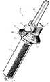
- FIG. 1is a schematic perspective view of a drip chamber with integrated flow regulator according to the invention
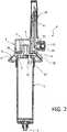
- FIG. 2is an axial cross-sectional view of FIG. 1 ;
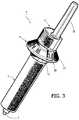
- FIG. 3shows a variant of FIG. 1 .
- a drip chamberbasically comprises a generally cylindrical body 1 made of transparent plastic material having one open end, which defines an inlet 2 , and a restricted opposite end, which defines an outlet 3 .
- a precision flow regulatordirectly applied on the inlet 2 is a precision flow regulator, designated as a whole by 4 .
- the flow regulator 4comprises, in a generally known way, a first body 5 and a second body 6 both made of moulded plastic material and coupled together in a rotary way via a central pin 7 , with the interposition of a gasket 8 .
- the first body 5is formed integrally with an axial inlet fitting 9 , the outer part of which is shaped like a perforating tip 10 , applied on which is a removable protection cap 11 .
- the inlet fitting 9is moreover formed integrally with a side aeration passage 12 with associated filter 13 and openable closing plug 14 .
- the second body 6is formed integrally with an outlet fitting 15 , communication of which with the inlet fitting 9 is finely and progressively adjustable by means of relative rotation between the bodies 5 and 6 , through dosage passages of said body 5 , one of which is designated as a whole by 16 in FIG. 2 .
- the modalities via which said progressive regulation is obtainedare generally known, and for reasons of brevity will not be described in detail.
- At least one graduated scale 17(or a different indication representing a greater or smaller flow rate) is provided, formed peripherally on the body 6 and co-operating with a window indicator 18 , formed integrally with the body 5 .
- the graduated scale 17can be conveniently made according to what is described and illustrated in the Italian patent application No. TO2005A00394, not published at the date of filing of the present application.
- the body 6is moreover formed integrally with an annular skirt 19 , projecting from the part opposite to the body 5 and fixed permanently on the outside of the inlet 2 of the drip chamber 1 , via gluing or with any suitable equivalent system.
- the outlet fitting 15contained within the skirt 19 , projects in this way within the body I of the drip chamber.
- FIG. 3differs from the preceding embodiment only as regards the absence of the side aeration passage and corresponding plug.
- This variantis usable in the case where the drip chamber is to be used for a sac for medical liquid, whilst the previous embodiment is designed for use with medical liquids contained in bottles.
- Integration between the body 1 of the drip chamber and the precision regulator 4advantageously enables, on the one hand, reduction and compacting of the number of the components necessary for the medical line to which the drip chamber is associated, and on the other renders appreciably more convenient and easy the operations of regulation of the flow through said line by the personnel responsible.
Landscapes
- Health & Medical Sciences (AREA)
- Vascular Medicine (AREA)
- Engineering & Computer Science (AREA)
- Anesthesiology (AREA)
- Biomedical Technology (AREA)
- Heart & Thoracic Surgery (AREA)
- Hematology (AREA)
- Life Sciences & Earth Sciences (AREA)
- Animal Behavior & Ethology (AREA)
- General Health & Medical Sciences (AREA)
- Public Health (AREA)
- Veterinary Medicine (AREA)
- Infusion, Injection, And Reservoir Apparatuses (AREA)
- External Artificial Organs (AREA)
- Medical Preparation Storing Or Oral Administration Devices (AREA)
Abstract
Description
This application is a claims priority from Italian Utility Model Application No. TO2005A000106 filed on Jul. 25, 2005, the entire disclosure of which is incorporated herein by reference.
The present invention relates to drip chambers formed by a generally cylindrical body having an inlet and an outlet, traditionally used in medical lines, for example for infusion or transfusion, to supply, in a dosed way, a medical liquid, normally contained in a sac or bottle, to a patient.
In use, set between the sac or bottle of the medical liquid and the drip chamber is a flow regulator, typically constituted by an elastic clamp for gripping with adjustable intensity a flexible pipe that connects the sac to the drip chamber. As an alternative to the elastic clamp, for dosage of the liquid a precision regulator of a rotary type can be used, which is also in any case distinct and separate from the drip chamber.
The purpose of the present invention is to provide a drip chamber of the aforesaid type, configured in such a way as to reduce the number of loose components of the medical line, ensuring at the same time a greater convenience and practicality of regulation during use.
According to the invention, the above purpose is achieved thanks to the fact that the drip chamber is integrated with a precision flow regulator.
According to a preferred embodiment of the invention the flow regulator comprises a first body with an inlet fitting and a second body with an outlet fitting coupled together in a rotary way, with the interposition of a gasket, to open progressively the communication between said inlet fitting and said outlet fitting through dosage passages, and in which the second body bears a graduated scale co-operating with an indicator carried by the first body and has an annular attachment skirt permanently fixed on the inlet end of the body of the drip chamber.
The invention will now be described in detail with reference to the annexed plate of drawings, which are provided purely by way of non-limiting example and in which:
With reference toFIGS. 1 and 2 , a drip chamber according to the invention basically comprises a generallycylindrical body 1 made of transparent plastic material having one open end, which defines aninlet 2, and a restricted opposite end, which defines anoutlet 3. According to the invention, directly applied on theinlet 2 is a precision flow regulator, designated as a whole by4.
Theflow regulator 4 comprises, in a generally known way, afirst body 5 and asecond body 6 both made of moulded plastic material and coupled together in a rotary way via acentral pin 7, with the interposition of agasket 8.
Thefirst body 5 is formed integrally with anaxial inlet fitting 9, the outer part of which is shaped like aperforating tip 10, applied on which is aremovable protection cap 11. Theinlet fitting 9 is moreover formed integrally with aside aeration passage 12 with associatedfilter 13 andopenable closing plug 14.
Thesecond body 6 is formed integrally with an outlet fitting15, communication of which with the inlet fitting9 is finely and progressively adjustable by means of relative rotation between thebodies body 5, one of which is designated as a whole by16 inFIG. 2 . The modalities via which said progressive regulation is obtained are generally known, and for reasons of brevity will not be described in detail.
For controlling regulation, at least one graduated scale17 (or a different indication representing a greater or smaller flow rate) is provided, formed peripherally on thebody 6 and co-operating with awindow indicator 18, formed integrally with thebody 5. The graduatedscale 17 can be conveniently made according to what is described and illustrated in the Italian patent application No. TO2005A00394, not published at the date of filing of the present application.
Thebody 6 is moreover formed integrally with anannular skirt 19, projecting from the part opposite to thebody 5 and fixed permanently on the outside of theinlet 2 of thedrip chamber 1, via gluing or with any suitable equivalent system. The outlet fitting15, contained within theskirt 19, projects in this way within the body I of the drip chamber.
The variant ofFIG. 3 , in which parts that are identical or similar to the ones already described with reference toFIGS. 1 and 2 are designated by the same reference numbers, differs from the preceding embodiment only as regards the absence of the side aeration passage and corresponding plug. This variant is usable in the case where the drip chamber is to be used for a sac for medical liquid, whilst the previous embodiment is designed for use with medical liquids contained in bottles.
Integration between thebody 1 of the drip chamber and theprecision regulator 4 advantageously enables, on the one hand, reduction and compacting of the number of the components necessary for the medical line to which the drip chamber is associated, and on the other renders appreciably more convenient and easy the operations of regulation of the flow through said line by the personnel responsible.
Of course the details of construction and the embodiments may vary widely with respect to what is described and illustrated herein, without thereby departing from the scope of the invention, as defined in the ensuing claims.
Claims (4)
1. A drip chamber for medical lines, including:
a generally cylindrical body having an inlet and an outlet and a precision flow regulator integrated therewith;
said precision flow regulator comprising a first body having an inlet fitting and a second body having an outlet fitting, said first and second body being coupled together in a rotary way with the interposition of a gasket so as to open progressively the communication between said inlet fitting and said outlet fitting through dosage passages, said second body having an annular attachment skirt permanently fixed on said inlet end of the body of the drip chamber;
said second body bearing a peripheral graduated scale co-operating with an indicator of said first body, said indicator consisting of an integral side appendage of said first body shaped as a window projecting from a side wall of said first body and over said graduated scale, so as to form a raised window framing at least one value of said peripheral graduated scale while leaving other values thereof visible.
2. The drip chamber according toclaim 1 , wherein said inlet fitting of the first body of said flow regulator is formed as a perforating tip.
3. The drip chamber according toclaim 2 , wherein said inlet fitting of the first body of said flow regulator further comprises an aeration passage with an associated filter and openable closing plug.
4. A drip chamber for medical lines, including:
a generally cylindrical body having an inlet and an outlet and a precision flow regulator integrated therewith;
said precision flow regulator comprising a first body having an inlet fitting and a second body having an outlet fitting, said first and second body being coupled together to allow rotation therebetween about an axis of said generally cylindrical body;
a gasket interposed between said first body and said second body and configured so as to open progressively a communication between said inlet fitting and said outlet fitting through dosage passages in response to a rotation of said first body and said second body relative to each other;
said inlet fitting and said outlet fitting located on opposite sides of said gasket axially relative to said axis of said generally cylindrical body, said inlet fitting and said outlet fitting having axes parallel and offset relative to each other;
said second body having on annular attachment skirt permanently fixed on an inlet end of the cylindrical body of the drip chamber, said outlet fitting extending into said inlet; and
said second body bearing a peripheral graduated scale co-operating with an indicator of said first body, said indicator consisting of an integral side appendage of said first body shaped as a window, said indicator projecting from a side wall of said first body and over said graduated scale of said second body, so as to form a raised window framing at least one value of said peripheral graduated scale inside said indicator, and wherein a remainder of said graduated scale is unframed by said indicator and uncovered to leave said graduated scale visible.
Applications Claiming Priority (3)
| Application Number | Priority Date | Filing Date | Title |
|---|---|---|---|
| ITTO20050106U | 2005-07-25 | ||
| ITTO2005U000106 | 2005-07-25 | ||
| IT000106UITTO20050106U1 (en) | 2005-07-25 | 2005-07-25 | DRIPPING CHAMBER WITH INTEGRATED FLOW REGULATOR FOR MEDICAL LINES |
Publications (2)
| Publication Number | Publication Date |
|---|---|
| US20070043325A1 US20070043325A1 (en) | 2007-02-22 |
| US7658726B2true US7658726B2 (en) | 2010-02-09 |
Family
ID=37072985
Family Applications (1)
| Application Number | Title | Priority Date | Filing Date |
|---|---|---|---|
| US11/492,652Active2027-07-02US7658726B2 (en) | 2005-07-25 | 2006-07-25 | Drip chamber with integrated flow regulator for medical lines |
Country Status (13)
| Country | Link |
|---|---|
| US (1) | US7658726B2 (en) |
| EP (1) | EP1747787B1 (en) |
| CN (1) | CN1923305B (en) |
| AT (1) | ATE418349T1 (en) |
| AU (1) | AU2006203148A1 (en) |
| CA (1) | CA2552692C (en) |
| DE (1) | DE602006004405D1 (en) |
| ES (1) | ES2318680T3 (en) |
| IT (1) | ITTO20050106U1 (en) |
| PT (1) | PT1747787E (en) |
| SG (1) | SG129402A1 (en) |
| TW (1) | TWI380833B (en) |
| ZA (1) | ZA200606022B (en) |
Families Citing this family (9)
| Publication number | Priority date | Publication date | Assignee | Title |
|---|---|---|---|---|
| JP6100472B2 (en)* | 2012-03-30 | 2017-03-22 | シャープ株式会社 | Measuring device, dialysis end condition judging device, and dialysis progress presentation device |
| US20140194832A1 (en)* | 2013-01-04 | 2014-07-10 | HUBIOMED Co., Ltd. | Instillator for injection of ringer's solution |
| KR101800664B1 (en)* | 2016-07-12 | 2017-11-23 | 주식회사 인성메디칼 | Float control assembly used in medical field |
| DE102017205250A1 (en)* | 2017-03-28 | 2018-10-04 | B. Braun Melsungen Ag | Piercing part for a medical infusion system |
| USD816831S1 (en)* | 2017-04-05 | 2018-05-01 | Alcor Scientific, Inc. | Drip chamber |
| DE202017002518U1 (en)* | 2017-05-04 | 2017-07-04 | B. Braun Melsungen Ag | Drip chamber arrangement for a medical infusion system |
| KR101874262B1 (en)* | 2017-11-15 | 2018-07-03 | 김재환 | Online trip and exercise system beyond time and space |
| US11452928B2 (en) | 2019-07-02 | 2022-09-27 | Jae Hwan Kim | System for providing virtual exercising place |
| JP1716544S (en)* | 2021-08-11 | 2022-06-02 | Drip chamber for medical lines |
Citations (14)
| Publication number | Priority date | Publication date | Assignee | Title |
|---|---|---|---|---|
| US4317473A (en) | 1979-12-31 | 1982-03-02 | Becton, Dickinson And Company | Fluid flow control assembly |
| US4343305A (en) | 1977-10-14 | 1982-08-10 | Dan Bron | Adjustable-rate, constant output infusion set |
| US4396016A (en)* | 1977-09-07 | 1983-08-02 | Becker Karl E | Intravenous solution flow regulator |
| US4869457A (en)* | 1986-09-10 | 1989-09-26 | Ewerloef Goeran | Arrangement for controlling and regulating a liquid flowing through a line |
| US5098407A (en)* | 1989-01-09 | 1992-03-24 | Terumo Kabushiki Kaisha | Medical piercing cannula with drip chamber |
| US5098408A (en) | 1990-02-12 | 1992-03-24 | General Automatic Corp. | Automatic intravenous flow controller |
| US5360412A (en)* | 1992-10-05 | 1994-11-01 | Nakao Naomi L | Method and device for regulating intravenous flow |
| US6261267B1 (en) | 1998-10-09 | 2001-07-17 | Globe Enterprises, Inc. | Automatic IV shut off valve |
| DE20216791U1 (en) | 2002-10-31 | 2003-02-06 | Fresenius Kabi Ab, Uppsala | Air bleed valve, for medical infusion fluid for small children, has two shut-off valves operating in opposite directions and with eccentric apertures |
| EP1312388A1 (en) | 2001-11-20 | 2003-05-21 | GVS S.r.l. | Device for regulating the flow rate of medical liquid directed towards a patient |
| WO2003047660A1 (en) | 2001-12-06 | 2003-06-12 | Sobem | Flow rate control device for medical use |
| US6619308B2 (en)* | 1999-07-09 | 2003-09-16 | I-Flow Corporation | Pressure regulator |
| US20070018129A1 (en)* | 2005-06-09 | 2007-01-25 | Industrie Borla S.P.A. | Flow regulator for medical liquids and method for its fabrication |
| US7327273B2 (en)* | 2004-02-12 | 2008-02-05 | Hung Orlando R | Fluid monitoring device |
- 2005
- 2005-07-25ITIT000106Upatent/ITTO20050106U1/enunknown
- 2006
- 2006-07-17SGSG200604806Apatent/SG129402A1/enunknown
- 2006-07-17DEDE602006004405Tpatent/DE602006004405D1/enactiveActive
- 2006-07-17PTPT06117317Tpatent/PT1747787E/enunknown
- 2006-07-17ATAT06117317Tpatent/ATE418349T1/ennot_activeIP Right Cessation
- 2006-07-17EPEP06117317Apatent/EP1747787B1/enactiveActive
- 2006-07-17ESES06117317Tpatent/ES2318680T3/enactiveActive
- 2006-07-18TWTW095126265Apatent/TWI380833B/enactive
- 2006-07-18CACA2552692Apatent/CA2552692C/enactiveActive
- 2006-07-20ZAZA200606022Apatent/ZA200606022B/enunknown
- 2006-07-24AUAU2006203148Apatent/AU2006203148A1/ennot_activeAbandoned
- 2006-07-25CNCN2006101263758Apatent/CN1923305B/enactiveActive
- 2006-07-25USUS11/492,652patent/US7658726B2/enactiveActive
Patent Citations (14)
| Publication number | Priority date | Publication date | Assignee | Title |
|---|---|---|---|---|
| US4396016A (en)* | 1977-09-07 | 1983-08-02 | Becker Karl E | Intravenous solution flow regulator |
| US4343305A (en) | 1977-10-14 | 1982-08-10 | Dan Bron | Adjustable-rate, constant output infusion set |
| US4317473A (en) | 1979-12-31 | 1982-03-02 | Becton, Dickinson And Company | Fluid flow control assembly |
| US4869457A (en)* | 1986-09-10 | 1989-09-26 | Ewerloef Goeran | Arrangement for controlling and regulating a liquid flowing through a line |
| US5098407A (en)* | 1989-01-09 | 1992-03-24 | Terumo Kabushiki Kaisha | Medical piercing cannula with drip chamber |
| US5098408A (en) | 1990-02-12 | 1992-03-24 | General Automatic Corp. | Automatic intravenous flow controller |
| US5360412A (en)* | 1992-10-05 | 1994-11-01 | Nakao Naomi L | Method and device for regulating intravenous flow |
| US6261267B1 (en) | 1998-10-09 | 2001-07-17 | Globe Enterprises, Inc. | Automatic IV shut off valve |
| US6619308B2 (en)* | 1999-07-09 | 2003-09-16 | I-Flow Corporation | Pressure regulator |
| EP1312388A1 (en) | 2001-11-20 | 2003-05-21 | GVS S.r.l. | Device for regulating the flow rate of medical liquid directed towards a patient |
| WO2003047660A1 (en) | 2001-12-06 | 2003-06-12 | Sobem | Flow rate control device for medical use |
| DE20216791U1 (en) | 2002-10-31 | 2003-02-06 | Fresenius Kabi Ab, Uppsala | Air bleed valve, for medical infusion fluid for small children, has two shut-off valves operating in opposite directions and with eccentric apertures |
| US7327273B2 (en)* | 2004-02-12 | 2008-02-05 | Hung Orlando R | Fluid monitoring device |
| US20070018129A1 (en)* | 2005-06-09 | 2007-01-25 | Industrie Borla S.P.A. | Flow regulator for medical liquids and method for its fabrication |
Non-Patent Citations (1)
| Title |
|---|
| European Search Report for EP 06117317.5-2310, dated Oct. 13, 2006. |
Also Published As
| Publication number | Publication date |
|---|---|
| CA2552692C (en) | 2014-04-22 |
| ATE418349T1 (en) | 2009-01-15 |
| EP1747787A1 (en) | 2007-01-31 |
| ES2318680T3 (en) | 2009-05-01 |
| CN1923305A (en) | 2007-03-07 |
| CA2552692A1 (en) | 2007-01-25 |
| ITTO20050106U1 (en) | 2007-01-26 |
| US20070043325A1 (en) | 2007-02-22 |
| EP1747787B1 (en) | 2008-12-24 |
| CN1923305B (en) | 2012-07-18 |
| ZA200606022B (en) | 2007-09-26 |
| TWI380833B (en) | 2013-01-01 |
| AU2006203148A1 (en) | 2007-02-08 |
| SG129402A1 (en) | 2007-02-26 |
| PT1747787E (en) | 2009-03-19 |
| DE602006004405D1 (en) | 2009-02-05 |
Similar Documents
| Publication | Publication Date | Title |
|---|---|---|
| US7658726B2 (en) | Drip chamber with integrated flow regulator for medical lines | |
| GB0129171D0 (en) | Improvements in and relating to a medicament cartridge | |
| US7150369B1 (en) | Dual chamber infant bottle | |
| WO2004089805A3 (en) | Multi-dose liquid dispensing assembly | |
| MX2007003539A (en) | Absorbent article with indicator. | |
| CN208003256U (en) | A kind of medical adjustable anti-pollution cotton swab | |
| CN111071618B (en) | Cover assembly capable of assisting pouring | |
| US20100288129A1 (en) | Device for treating and purifying a liquid product | |
| CN103357091B (en) | Disposable liquid stop infusion apparatus | |
| CN205145215U (en) | Take drainage bag against current of preventing of cross valve | |
| CN209900269U (en) | Transfusion bottle type transfusion device | |
| CN202379233U (en) | Purified water barrel | |
| CN207644874U (en) | A kind of extrusion recorder jar | |
| CN222584967U (en) | Integrated scraping board with care solution | |
| CN206151132U (en) | Special quantitative drinking cup of postoperative | |
| CN208585562U (en) | Packing container | |
| CN212074923U (en) | Double-layer glass bottle for containing 98 composite iodine disinfectant | |
| CN210813047U (en) | Transfusion connecting pipe convenient for exhaust | |
| CN210794321U (en) | Cosmetic emulsion split charging bottle | |
| EP3574940B1 (en) | Drip chamber and spike assembly for medical lines | |
| CN204767747U (en) | Drainage core location structure of water purification filter core | |
| CN219127999U (en) | Combined permeation promoting device | |
| CN216093505U (en) | Automatic liquid preparation system capable of improving liquid preparation accuracy | |
| CN210259601U (en) | Quantitative liquid feeding device for pesticide synergist | |
| CN205589778U (en) | Liquid medicine bottle with structure is taken to ration |
Legal Events
| Date | Code | Title | Description |
|---|---|---|---|
| AS | Assignment | Owner name:INDUSTRIE BORLA S.P.A.,ITALY Free format text:ASSIGNMENT OF ASSIGNORS INTEREST;ASSIGNOR:GUALA, GIANNI;REEL/FRAME:018306/0500 Effective date:20060915 Owner name:INDUSTRIE BORLA S.P.A., ITALY Free format text:ASSIGNMENT OF ASSIGNORS INTEREST;ASSIGNOR:GUALA, GIANNI;REEL/FRAME:018306/0500 Effective date:20060915 | |
| STCF | Information on status: patent grant | Free format text:PATENTED CASE | |
| FEPP | Fee payment procedure | Free format text:PAYOR NUMBER ASSIGNED (ORIGINAL EVENT CODE: ASPN); ENTITY STATUS OF PATENT OWNER: SMALL ENTITY | |
| FPAY | Fee payment | Year of fee payment:4 | |
| FPAY | Fee payment | Year of fee payment:8 | |
| MAFP | Maintenance fee payment | Free format text:PAYMENT OF MAINTENANCE FEE, 12TH YR, SMALL ENTITY (ORIGINAL EVENT CODE: M2553); ENTITY STATUS OF PATENT OWNER: SMALL ENTITY Year of fee payment:12 |