US7658718B2 - Biopsy needle with integrated guide pin - Google Patents
Biopsy needle with integrated guide pinDownload PDFInfo
- Publication number
- US7658718B2 US7658718B2US11/958,500US95850007AUS7658718B2US 7658718 B2US7658718 B2US 7658718B2US 95850007 AUS95850007 AUS 95850007AUS 7658718 B2US7658718 B2US 7658718B2
- Authority
- US
- United States
- Prior art keywords
- needle
- pin
- hubs
- arm
- biopsy
- Prior art date
- Legal status (The legal status is an assumption and is not a legal conclusion. Google has not performed a legal analysis and makes no representation as to the accuracy of the status listed.)
- Expired - Fee Related, expires
Links
- 238000001574biopsyMethods0.000titleclaimsabstractdescription107
- 238000003780insertionMethods0.000claimsdescription5
- 230000037431insertionEffects0.000claimsdescription5
- 125000006850spacer groupChemical group0.000description14
- 230000008901benefitEffects0.000description5
- 238000000034methodMethods0.000description4
- 238000012986modificationMethods0.000description3
- 230000004048modificationEffects0.000description3
- 238000000465mouldingMethods0.000description3
- 230000009471actionEffects0.000description2
- 230000001010compromised effectEffects0.000description2
- 238000010304firingMethods0.000description2
- 238000004519manufacturing processMethods0.000description2
- 230000001960triggered effectEffects0.000description2
- 230000004913activationEffects0.000description1
- 230000004075alterationEffects0.000description1
- 238000005452bendingMethods0.000description1
- 239000012530fluidSubstances0.000description1
- 230000002452interceptive effectEffects0.000description1
- 230000007246mechanismEffects0.000description1
- 238000012858packaging processMethods0.000description1
- 230000008569processEffects0.000description1
- 230000001737promoting effectEffects0.000description1
Images


Classifications
- A—HUMAN NECESSITIES
- A61—MEDICAL OR VETERINARY SCIENCE; HYGIENE
- A61B—DIAGNOSIS; SURGERY; IDENTIFICATION
- A61B10/00—Instruments for taking body samples for diagnostic purposes; Other methods or instruments for diagnosis, e.g. for vaccination diagnosis, sex determination or ovulation-period determination; Throat striking implements
- A61B10/02—Instruments for taking cell samples or for biopsy
- A61B10/0233—Pointed or sharp biopsy instruments
- A61B10/0266—Pointed or sharp biopsy instruments means for severing sample
- A61B10/0275—Pointed or sharp biopsy instruments means for severing sample with sample notch, e.g. on the side of inner stylet
- A—HUMAN NECESSITIES
- A61—MEDICAL OR VETERINARY SCIENCE; HYGIENE
- A61B—DIAGNOSIS; SURGERY; IDENTIFICATION
- A61B17/00—Surgical instruments, devices or methods
- A61B17/34—Trocars; Puncturing needles
- A61B17/3403—Needle locating or guiding means
- A—HUMAN NECESSITIES
- A61—MEDICAL OR VETERINARY SCIENCE; HYGIENE
- A61B—DIAGNOSIS; SURGERY; IDENTIFICATION
- A61B10/00—Instruments for taking body samples for diagnostic purposes; Other methods or instruments for diagnosis, e.g. for vaccination diagnosis, sex determination or ovulation-period determination; Throat striking implements
- A61B10/02—Instruments for taking cell samples or for biopsy
- A61B2010/0208—Biopsy devices with actuators, e.g. with triggered spring mechanisms
- A—HUMAN NECESSITIES
- A61—MEDICAL OR VETERINARY SCIENCE; HYGIENE
- A61B—DIAGNOSIS; SURGERY; IDENTIFICATION
- A61B90/00—Instruments, implements or accessories specially adapted for surgery or diagnosis and not covered by any of the groups A61B1/00 - A61B50/00, e.g. for luxation treatment or for protecting wound edges
- A61B90/03—Automatic limiting or abutting means, e.g. for safety
- A61B2090/033—Abutting means, stops, e.g. abutting on tissue or skin
- A61B2090/034—Abutting means, stops, e.g. abutting on tissue or skin abutting on parts of the device itself
Definitions
- the present inventionrelates to an improved biopsy needle suited for use in a biopsy gun, or for use as a surgical instrument.
- Biopsy needlesas part of a biopsy system, are generally used in the medical field to remove tissue, cells or fluids from a body for examination.
- Known biopsy needleshave at least one inner needle (stylet) and an outer needle (cannula).
- the stylethas a point to enable insertion of the needle into a body, and a recess or notch located near its distal end for receiving a tissue sample.
- the cannulais displaceably guided on the stylet and has sharp cutting edges.
- Both the stylet and cannulahave a connecting element on their proximal ends to enable connection of the needle to the slides of a biopsy gun.
- the connecting elements in known biopsy needlesgenerally have included either flanges that cooperate with matching contact surfaces on the slides, or recesses that engage a rib located on a slide wherein both the slide and the rib run along the length of the biopsy needle.
- Some prior art biopsy needleshave the disadvantage that it is sometimes difficult to insert them into the biopsy gun under sterile conditions.
- Some prior art biopsy gunsrequire a certain spacing between the connecting elements on the stylet and cannula in order for the biopsy needle to be inserted into the biopsy gun.
- this task of inserting the biopsy needle into the biopsy gun while the connecting elements are maintained in a fixed orientationis difficult because the stylet is generally freely displaceable in the cannula. Therefore, it is generally necessary to align the connecting elements of the biopsy needle, either manually or through use of a separate spacer, prior to insertion into a biopsy gun.
- a spacer clipAfter the biopsy needle is inserted into a biopsy gun, if a spacer clip is used, it is generally necessary to remove the spacer in order to close the lid and operate the biopsy gun.
- Conventional spacer clipsrequire the molding of a separate spacer. This requirement of a separate molding step adds an additional step in the manufacturing and packaging process thereby increasing the costs to produce the biopsy needle.
- the use of a separate spacer clipmay require undue handling of the needle in order to connect and disconnect the spacer clip.
- some conventional biopsy gunsdo not permit the option of inserting the needle into a biopsy gun in the uncocked position.
- the present inventionincludes a biopsy needle particularly suited for use in a biopsy gun.
- the inventionincludes an integrated guide pin and a stop engagement.
- the guide pin stop engagementprevents disengagement of the cannula and the stylet, facilitates needle alignment without the use of extrinsic devices and prevents rotation and other movement of the inner and outer needles relative to each other and the slides in a biopsy gun.
- the integrated design of the needleallows the needle to be easily prepackaged in a sterile, disposable condition.
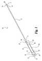
- FIG. 1is a side elevational view of a biopsy needle according to this invention.
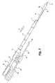
- FIG. 2is a top perspective view of a biopsy needle of this invention shown in the first position.
- FIG. 3is a top perspective view of the needle of FIG. 2 shown in the second position.
- FIG. 4is a partial bottom perspective view of the second hub of the needle of FIG. 2 shown approaching the second position.
- FIG. 5is a partial bottom perspective view of the second hub of the needle of FIG. 2 shown in the second position.
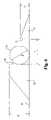
- FIG. 6is a side view of a portion of the second hub showing the relationship between the ramp and the stop member.
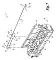
- FIG. 7is an isometric view of one embodiment of the biopsy needle of the present invention used in conjunction with a biopsy gun of a type that is well-known in the art.
- FIG. 8is a top perspective view of another embodiment of a biopsy needle assembly with the first and second hubs in a second closed position.
- FIG. 9is a top view of the first hub of the biopsy needle assembly shown in FIG. 8
- FIG. 10is a top view of the second hub of the biopsy needle assembly shown in FIG. 8 .
- FIG. 11is a top view of the biopsy needle assembly shown in FIG. 8 with the first and second hubs in a first extended position for loading into a biopsy gun of the type shown in FIG. 7 .
- FIG. 12is a side cross-sectional view of the biopsy needle assembly shown in FIG. 11 , taken along line 12 - 12 as viewed in the direction of the arrows.
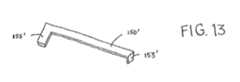
- FIG. 13is a top perspective view of the elongated pin as a flat wire.
- the present inventionprovides a biopsy needle having an integrated guide pin and a stop engagement.
- a preferred embodiment of a biopsy instrument 10 for use in a biopsy gun of this inventionis shown schematically in FIG. 1 .
- Instrument 10includes a hollow outer needle 12 having a proximal end 14 and a distal end 16 and defining a lumen therethrough.
- An inner needle 20is slidably engaged within the lumen.
- a first hub 30is attached to the proximal end 22 of the inner needle.
- a second hub 35is attached to the proximal end 14 of the outer needle 12 .
- the first hub 30defines a longitudinally extending bore 32 for holding the proximal end 22 of inner needle 20 .
- Bore 32may extend through the entire length of the first hub 30 ; however it is not necessary so long as the proximal end 22 of inner needle is securely attached.
- Hub 30also includes means for engaging the carriage of a biopsy device.
- the meansincludes a vertically extending bore 31 as shown in FIG. 1 .
- the second hub 35may be identical to the first hub 30 , except that the longitudinally extending bore 37 should extend through the entire length of the second hub 35 .
- the longitudinally extending bore 37 of the second hub 35holds the proximal end 14 of the outer needle 12 .
- the second hub 35further includes a second vertically extending bore 36 adapted to engage the carriage of a biopsy device.
- hubs 30 , 35may be identical.
- the hubs 30 , 35may be formed by insert molding and other techniques that are known in the art.
- the hubs 30 , 35are insert molded around inner needle 20 and outer needle 12 , respectively.
- the preferred embodimentillustrates vertically extending bores 31 , 36 in the hubs 30 , 35 for engagement to the slides of a biopsy gun, other configurations may be used, such as, for example, flanges.
- the hubs 30 , 35are moveable/slidable relative to one another between a first position shown in FIG. 2 wherein the distal end 24 of the inner needle 20 is retracted within the lumen and a second position shown in FIG. 3 .
- the distal end 24 of the inner needle 20is extended away from the outer needle 12 to expose a cavity 25 defined adjacent the distal end 24 of the inner needle 20 .
- the cavity 25is covered by the outer needle 12 .
- the design of the outer needle 12 and the inner needle 20is generally well known in the art, and one or both may have a beveled cutting edge 17 , 26 on their distal ends 16 , 24 , respectively.
- the inner needle 20 and the outer needle 12may be of a variety of gauge sizes.
- the gauge and length of the inner needle and outer needlevaries with the procedure for which it will be used.
- the needlesare provided in lengths between 10 cm to 29 cm and gauge sizes of 20 gauge to 12 gauge.
- An elongated pin 50is provided to maintain proper relationships between the hubs 30 , 35 .
- the first end 53 of the pin 50is fixedly attached to the first hub 30 .
- the first end 53 of the pinis engaged within a second longitudinal bore 33 defined through first hub 30 ( FIG. 1 ).
- Second hub 35 and the pin 50are slidable or moveable relative to each other, or in other words, second hub 35 is moveable relative to the pin 50 between the first and second ends 53 , 56 .
- the length of the pinmay be configured to allow the biopsy needle 10 of the present invention to be used in various biopsy guns.
- a stop engagementis provided between the second end 56 of the pin 50 and the second hub 35 , which prevents disengagement of the outer and inner needles 12 , 20 .
- the stop engagementinvolves an engagement member at the second end 56 , which is configured to engage the second hub 35 when the second hub 35 is at the second end 56 of pin 50 .
- a track 38which runs parallel to the outer needle 12 , is provided on the second hub 35 .
- the track 38may be defined by the surface 41 , a wall member 44 projecting from the surface 41 and a dog 46 projecting from the wall 44 .
- Pin 50is slidably disposed within track 38 .
- the shaft 54 of pin 50runs parallel to the needles 12 , 20 , and the second hub 35 is slidable along the pin 50 between a location 58 near the first end 53 and the second end 56 .
- a stop member 60projects from surface 41 of the second hub 35 adjacent the track 38 .
- the engagement memberengages the second hub 35 at the stop member 60 .
- the engagement memberis an arm 55 projecting from the second end 56 of the pin 50 .
- arm 55is formed from a bend in pin 50 .
- any suitable means of creating arm 55is contemplated.
- the embodiment shownfurther includes a ramp 70 projecting from the surface 41 at a location distal to the stop member 60 .
- Ramp 70is inclined towards stop member 60 .
- Ramp 70includes a ramp head 72 facing stop member 60 .
- the space 80 between ramp 72 and stop member 60has a length L that is at least as large as a cross sectional dimension of said arm 55 .
- the cross sectional dimensionis the diameter D.
- Stop member 60has a height H that is sufficient to prevent arm 55 to roll over stop member during operation of the device 10 .
- Ramphas a height h sufficient to prevent the arm 55 from backing over the ramp 70 as the biopsy instrument 10 is inserted into the biopsy gun.
- ramp 70has a height h of at least about one third of the height of the arm 55 .
- the heightwill be the diameter D.
- ramp 55has a height D sufficient to provide a tactile indication when arm 55 slides over ramp 70 and into said space 80 .
- Some embodiments of the biopsy needle 10 of this inventionprovide several advantages over conventional biopsy needles and even those conventional biopsy needles that employ separate and integral spacer clips.
- the biopsy needle 10 of the present inventionWhen the biopsy needle 10 of the present invention is in the first position as shown in FIG. 5 , the first and second hubs 30 , 35 are in the maximally displaced position. With the arm 55 within space 80 , the user may easily insert the biopsy needle 10 into the gun without moving the position of the hubs 30 , 35 relative to each other. In this position, the distance between the vertical bores 31 , 36 is sufficient to align these holes with posts located on the slides of a cocked biopsy gun. In addition the hubs, and therefore the needles, are kept in proper rotational alignment.
- biopsy needle 10can be loaded into a biopsy gun without manipulation of the hubs 30 , 35 .
- some integrated spacer devicesprovide these same advantages, it is believed that some of them achieve these benefits at the expense of creating drag on the hubs during firing. Since these prior integrated spacers require a tight friction fit with the hubs, movement of the hubs within the gun may be compromised.
- the biopsy needle 10 of this inventioncan be inserted into a biopsy gun either in the cocked or uncocked position to accommodate the user's preference.
- the pin 50also facilitates removal of the biopsy needle 10 from a biopsy gun without the necessity to reattach a spacer clip as is required with some prior biopsy needles. If the biopsy needle 10 is inserted while the gun is uncocked, the gun should be cocked prior to use.
- the device 10can be shipped in the second position ( FIG. 3 ) with the hubs 30 , 35 close together. Insertion of the biopsy needle 10 into a biopsy gun 90 is generally straight forward as shown in FIGS. 4 , 5 and 7 .
- the usermoves the second hub 35 away from the first hub 30 towards the distal end 16 , which moves the outer needle 12 to cover the cavity 25 of inner needle 20 .
- arm 55encounters the ramp 70 and travels over the incline and into the space 80 and contacts the stop member 60 .
- the userfeels a definite click. This tactile indicator tells the user that the device is in position to be loaded.
- the deviceis now in the first position shown in FIG. 2 .
- the outer needle 12is positioned over cavity 25 , the beveled tip 26 of inner needle 20 is exposed, and the rotational relationship of the hubs and, as a result, the needle cavity and beveled tips, is fixed.
- the distance between the bore 31 in the first hub 30 and the bore 36 in the second hub 35is such that the biopsy needle 10 can be inserted with the proper spacing into a biopsy gun in the cocked position as shown in FIG. 7 .
- the hubs 30 , 35are also in proper orientation for operation of the gun 90 . This eliminates the need for any external means of achieving the proper spacing of the needle.
- the needlecan be mounted in a biopsy gun in the uncocked position.
- One of the hubsis grasped by the user and placed over the interior chamber of the biopsy gun 90 , as illustrated in FIG. 7 .
- Vertically extending bores 31 , 36 of the first and second hubs 30 , 35are aligned over the slides 91 , 92 of the biopsy gun 90 and receive posts 93 , 94 , respectively. Without having to remove the integrated pin 50 , the lid 95 to the biopsy gun 90 is closed and is ready for use.
- the tip 26 of inner needle 20is exposed to facilitate insertion of the biopsy needle 10 into the tissue being sampled.
- the biopsy gunis then triggered causing the first hub 30 and the pin 50 to move forward towards the distal end in the direction of arrow F, while the second hub 35 is held stationary.
- This movementcauses the inner needle 20 to move forward into the tissue being sampled and exposes the cavity 25 , which receives the tissue to be sampled.
- the deviceis now in the second position depicted in FIG. 3 .
- the arm 55must overcome the ramp head 72 to move out of space 80 . While the arm 55 will not back out over the ramp 70 during loading of the gun 90 , the force of the gun 90 is more than sufficient to smoothly overcome the ramp head 72 without interfering with the action of the gun 90 .
- the second slide 92 of the biopsy gun 90is then triggered moving the second hub 35 forward in the direction of arrow F.
- This actioncauses the outer needle 12 to move forward over cavity 25 , which causes outer needle 12 to separate and trap tissue prolapsed in the cavity 25 .
- the device 10has returned to the first position shown in FIG. 2 with the arm 55 in the space 80 ( FIG. 5 ).
- the biopsy needle 10can then be removed and the tissue examined.
- the pin 50 in engagement with the first and second hubs 30 , 35 during operation of the biopsy gun 90stabilizes the first and second hubs 30 , 35 and prevents twisting and bending in the biopsy gun 90 .
- the hubs 30 , 35are fixed rotationally relative to one another due to the fixed connection of the first end 53 of the pin 50 within the longitudinal bore 33 of the first hub 30 and the cooperation of the longitudinal bore 33 , the track 38 , and the dog 46 to prevent rotation of the hubs 30 , 35 relative to each other.
- a biopsy needle assembly 100shown in FIG. 8 , includes an outer needle 112 and an inner needle 120 that may be configured similar to the needles 12 and 20 described above.
- the inner needle 120is fixed to a first rearmost hub 130
- the outer needle 112is fixed to a second forward hub 135 , again in a manner similar to that described above.
- Both hubsinclude carriage engagement features 131 , 136 , respectively that are configured to allow the biopsy needle assembly 100 to be mounted within a biopsy gun, such as the gun depicted in FIG. 7 .
- the guide pin 150is oriented above the inner needle 120 extending from the first hub 130 , as best seen in FIGS. 11 , 12 .
- the first hubthus includes an elongated track 133 sized to receive the pin 150 therein, as illustrated in FIG. 9 .
- the hub 130further defines a bore 134 at one end of the track to receive the bent first end 153 of the pin.
- the walls 133 a of the track 133can be configured to form a snap-fit engagement about the pin to firmly hold the pin 150 to the first hub 130 .
- the trackdefines a channel 133 b between the walls that can fit snugly about the pin.
- the second hub 135also defines a second track 138 directly above the engagement between the outer needle 112 and the hub 135 , as shown in FIG. 10 .
- the second track 138is configured to allow the pin 150 to slide within the track as the biopsy needle activation propels the first hub forward toward the second hub, as described above.
- the walls 138 a of the track 138may be configured for a snap-fit engagement, but with sufficient clearance in the channel 133 b for the pin to slide smoothly therein.
- the pin 150includes an arm 155 at the second end 156 of the pin. This arm is configured to engage a stop and ramp defined on the second hub 135 in a manner similar to that described above with respect to pin 50 .
- the stop surface 160is defined by the end of the track 138 , as illustrated in FIG. 10 .
- a projection or ramp element 170Offset from this stop surface 160 is a projection or ramp element 170 .
- the projectionhas a height from the body of the hub 135 that is sufficient to retain the arm 155 of the pin between the projection and the stop surface, such as when the two hubs are in their extended position shown in FIGS. 11 , 12 .
- the projection 170must further have a height that can be easily traversed by the arm 155 of the pin when the hubs are activated by the biopsy needle carriage mechanisms. Consequently, the projection or ramp element 170 may have the same dimensional relationship to the arm 155 of the pin 150 as between the ramp 70 and pin 50 described above in connection with FIG. 6 .
- the element 170may further incorporate a ramp head similar to the ramp head 72 and a beveled surface similar to that shown in FIG. 6 .
- one ramp 170is provided off to one side of the track 138 .
- the position of the rampis dictated by the direction at which the arm 155 of the pin 150 is bent. It is of course contemplated that an arm 155 that is 180° offset from the position shown in the figures would necessitate that the ramp 170 be positioned on the opposite side the track from what is illustrated.
- a rampmay be provided on both sides of the track.
- the end 156 of the pin 150may be configured as a “T”, with arms 155 projecting toward both sides.
- the pin 150may include a notch 151 formed adjacent the second end 156 and arm 155 .
- the notch 151provides a region of reduces cross-sectional area adjacent the free end of the pin.
- the arrangement of the tracks 133 and 138 and the pin 150help maintain the hubs 130 , 135 in alignment within a common plane when the hubs are in their extended position depicted in FIGS. 11 , 12 .
- the pinalso helps hold the angular orientation between the hubs in that extended position.
- arm 55engages another portion of the second hub 35 , such as wall member 48 .
- pin 50is rotated 180°, and the stop member 60 is not required.
- pins 50 , 150are shown as a cylindrical wire.
- a pin 150 ′may be formed of flat wire as shown in FIG. 13 , with appropriate modifications to the tracks for sliding contact with the respective pins.
- pin 150 ′includes an arm 155 ′ and a bent first end 153 ′ that have the same dimensional relationship as the arm and bent end in the other embodiments described above.
- the pins 50 , 150are shown anchored to the first hub 30 , 130 , respectively.
- the first ends 53 , 153 of the respective pinsmay be anchored to the corresponding second hub 35 , 135 , with the pins extending rearward toward the first hub 30 , 130 .
- the ramp and stop componentswould be formed on the first hub, rather than on the second hub.
- the ramp element 70presents beveled configuration that the arm 55 of the pin rides up as the two hubs are moved to their extended positions.
- the beveled ramp featuremay be incorporated into the arm to allow the arm to ride up the element 70 , which may or may not be similarly beveled.
Landscapes
- Health & Medical Sciences (AREA)
- Life Sciences & Earth Sciences (AREA)
- Medical Informatics (AREA)
- Engineering & Computer Science (AREA)
- Biomedical Technology (AREA)
- Heart & Thoracic Surgery (AREA)
- Pathology (AREA)
- Molecular Biology (AREA)
- Surgery (AREA)
- Animal Behavior & Ethology (AREA)
- General Health & Medical Sciences (AREA)
- Public Health (AREA)
- Veterinary Medicine (AREA)
- Infusion, Injection, And Reservoir Apparatuses (AREA)
Abstract
Description
Claims (14)
Priority Applications (4)
| Application Number | Priority Date | Filing Date | Title |
|---|---|---|---|
| US11/958,500US7658718B2 (en) | 2002-05-31 | 2007-12-18 | Biopsy needle with integrated guide pin |
| PCT/US2008/081712WO2009079100A1 (en) | 2007-12-18 | 2008-10-30 | Biopsy needle with integrated guide pin |
| EP08862605.6AEP2231023A4 (en) | 2007-12-18 | 2008-10-30 | Biopsy needle with integrated guide pin |
| US12/698,709US8167819B2 (en) | 2002-05-31 | 2010-02-02 | Biopsy needle with integrated guide pin |
Applications Claiming Priority (3)
| Application Number | Priority Date | Filing Date | Title |
|---|---|---|---|
| US10/159,692US6918881B2 (en) | 2002-05-31 | 2002-05-31 | Biopsy needle with integrated guide pin |
| US11/157,569US7309317B2 (en) | 2002-05-31 | 2005-06-21 | Biopsy needle with integrated guide pin |
| US11/958,500US7658718B2 (en) | 2002-05-31 | 2007-12-18 | Biopsy needle with integrated guide pin |
Related Parent Applications (1)
| Application Number | Title | Priority Date | Filing Date |
|---|---|---|---|
| US11/157,569Continuation-In-PartUS7309317B2 (en) | 2002-05-31 | 2005-06-21 | Biopsy needle with integrated guide pin |
Related Child Applications (1)
| Application Number | Title | Priority Date | Filing Date |
|---|---|---|---|
| US12/698,709ContinuationUS8167819B2 (en) | 2002-05-31 | 2010-02-02 | Biopsy needle with integrated guide pin |
Publications (2)
| Publication Number | Publication Date |
|---|---|
| US20080161719A1 US20080161719A1 (en) | 2008-07-03 |
| US7658718B2true US7658718B2 (en) | 2010-02-09 |
Family
ID=40795843
Family Applications (2)
| Application Number | Title | Priority Date | Filing Date |
|---|---|---|---|
| US11/958,500Expired - Fee RelatedUS7658718B2 (en) | 2002-05-31 | 2007-12-18 | Biopsy needle with integrated guide pin |
| US12/698,709Expired - LifetimeUS8167819B2 (en) | 2002-05-31 | 2010-02-02 | Biopsy needle with integrated guide pin |
Family Applications After (1)
| Application Number | Title | Priority Date | Filing Date |
|---|---|---|---|
| US12/698,709Expired - LifetimeUS8167819B2 (en) | 2002-05-31 | 2010-02-02 | Biopsy needle with integrated guide pin |
Country Status (3)
| Country | Link |
|---|---|
| US (2) | US7658718B2 (en) |
| EP (1) | EP2231023A4 (en) |
| WO (1) | WO2009079100A1 (en) |
Cited By (6)
| Publication number | Priority date | Publication date | Assignee | Title |
|---|---|---|---|---|
| US20100160829A1 (en)* | 2002-05-31 | 2010-06-24 | Promex Technologies, Llc | Biopsy Needle with Integrated Guide Pin |
| US8864682B2 (en) | 2007-12-27 | 2014-10-21 | Devicor Medical Products, Inc. | Clutch and valving system for tetherless biopsy device |
| US9468424B2 (en) | 2009-06-12 | 2016-10-18 | Devicor Medical Products, Inc. | Cutter drive assembly for biopsy device |
| US9724073B2 (en) | 2012-04-16 | 2017-08-08 | Jeff M. Hathaway | Biopsy device |
| US10456120B2 (en) | 2013-11-05 | 2019-10-29 | C. R. Bard, Inc. | Biopsy device having integrated vacuum |
| US10463350B2 (en) | 2015-05-01 | 2019-11-05 | C. R. Bard, Inc. | Biopsy device |
Families Citing this family (30)
| Publication number | Priority date | Publication date | Assignee | Title |
|---|---|---|---|---|
| US8109885B2 (en) | 2002-03-19 | 2012-02-07 | C. R. Bard, Inc. | Biopsy device for removing tissue specimens using a vacuum |
| EP1524940B1 (en) | 2002-03-19 | 2011-08-24 | Bard Dublin ITC Limited | Biopsy device and biopsy needle module that can be inserted into the biopsy device |
| DE10314240B4 (en) | 2003-03-29 | 2025-05-28 | Bard Dublin Itc Ltd. | Pressure generation unit |
| JP4814229B2 (en) | 2004-07-09 | 2011-11-16 | バード ペリフェラル ヴァスキュラー インコーポレイテッド | Transport device for biopsy device |
| US7517321B2 (en) | 2005-01-31 | 2009-04-14 | C. R. Bard, Inc. | Quick cycle biopsy system |
| EP1921998B8 (en) | 2005-08-10 | 2021-07-07 | C.R.Bard, Inc. | Single-insertion, multiple sampling biopsy device with linear drive |
| ES2539578T3 (en) | 2005-08-10 | 2015-07-02 | C.R. Bard, Inc. | Multi-sample biopsy device and single insert with various transport systems |
| JP4991723B2 (en) | 2005-08-10 | 2012-08-01 | シー・アール・バード・インコーポレーテッド | Single insertion multiple sampling biopsy device with integrated marker |
| EP3417792B1 (en) | 2006-08-21 | 2022-03-02 | C. R. Bard, Inc. | Self-contained handheld biopsy needle |
| SI2086418T1 (en) | 2006-10-06 | 2011-05-31 | Bard Peripheral Vascular Inc | Tissue handling system with reduced operator exposure |
| US8262586B2 (en) | 2006-10-24 | 2012-09-11 | C. R. Bard, Inc. | Large sample low aspect ratio biopsy needle |
| US8241225B2 (en) | 2007-12-20 | 2012-08-14 | C. R. Bard, Inc. | Biopsy device |
| WO2010107424A1 (en) | 2009-03-16 | 2010-09-23 | C.R. Bard, Inc. | Biopsy device having rotational cutting |
| AU2009344276B2 (en) | 2009-04-15 | 2014-06-05 | C.R. Bard, Inc. | Biopsy apparatus having integrated fluid management |
| US9173641B2 (en) | 2009-08-12 | 2015-11-03 | C. R. Bard, Inc. | Biopsy apparatus having integrated thumbwheel mechanism for manual rotation of biopsy cannula |
| US8430824B2 (en) | 2009-10-29 | 2013-04-30 | Bard Peripheral Vascular, Inc. | Biopsy driver assembly having a control circuit for conserving battery power |
| US8485989B2 (en) | 2009-09-01 | 2013-07-16 | Bard Peripheral Vascular, Inc. | Biopsy apparatus having a tissue sample retrieval mechanism |
| US8597206B2 (en) | 2009-10-12 | 2013-12-03 | Bard Peripheral Vascular, Inc. | Biopsy probe assembly having a mechanism to prevent misalignment of components prior to installation |
| US9498248B2 (en) | 2010-10-05 | 2016-11-22 | Medtronic, Inc. | Retainer for immobilizing an implanted catheter during stylet retraction, and stylet holder for use with same |
| CA2902221A1 (en) | 2013-03-20 | 2014-09-25 | Bard Peripheral Vascular, Inc. | Biopsy device |
| BR202013024295Y1 (en)* | 2013-09-23 | 2019-04-02 | Dorival Paronetto | ARRANGEMENT INTRODUCED IN MOTORIZED TRIGGER FOR BIOPSY SAMPLE COLLECTION |
| US20170209130A1 (en)* | 2014-07-31 | 2017-07-27 | Vincenzo CENNAMO | Device for taking samples of tissue for cytological/histological tests |
| US10076387B2 (en) | 2015-06-18 | 2018-09-18 | Medtronic, Inc. | Medical device implantation and positioning system |
| US11844500B2 (en) | 2017-05-19 | 2023-12-19 | Merit Medical Systems, Inc. | Semi-automatic biopsy needle device and methods of use |
| US11793498B2 (en) | 2017-05-19 | 2023-10-24 | Merit Medical Systems, Inc. | Biopsy needle devices and methods of use |
| US11116483B2 (en) | 2017-05-19 | 2021-09-14 | Merit Medical Systems, Inc. | Rotating biopsy needle |
| WO2020146968A1 (en)* | 2019-01-14 | 2020-07-23 | 王沁 | Biopsy needle and puncture biopsy device |
| US12295556B2 (en) | 2019-09-27 | 2025-05-13 | Merit Medical Systems, Inc. | Rotation biopsy system and handle |
| US12150627B2 (en) | 2019-12-11 | 2024-11-26 | Merit Medical Systems, Inc. | Bone biopsy device and related methods |
| CN114403939A (en)* | 2022-01-17 | 2022-04-29 | 利福昇(苏州)医疗科技有限公司 | Biopsy needle machine body assembly |
Citations (5)
| Publication number | Priority date | Publication date | Assignee | Title |
|---|---|---|---|---|
| US5121751A (en) | 1990-03-16 | 1992-06-16 | Ryder International Corporation | Instrument for tissue sampling |
| US5249582A (en)* | 1991-08-30 | 1993-10-05 | Hart Enterprises | Oriented biopsy needle assembly |
| EP1290978A2 (en)* | 2001-09-07 | 2003-03-12 | Gallini S.r.l. | Needle set for biopsy |
| US6918881B2 (en)* | 2002-05-31 | 2005-07-19 | Promex Technologies, Llc | Biopsy needle with integrated guide pin |
| US20050203439A1 (en) | 2002-03-19 | 2005-09-15 | Norbert Heske | Vacuum biopsy device |
Family Cites Families (5)
| Publication number | Priority date | Publication date | Assignee | Title |
|---|---|---|---|---|
| EP0540846B1 (en)* | 1991-09-27 | 1996-05-15 | Dlp, Inc. | Biopsy needle with spacer |
| US5236334A (en)* | 1991-12-16 | 1993-08-17 | Bennett Lavon L | Core biopsy needle units for use with automated biopsy guns |
| US5876354A (en)* | 1996-05-01 | 1999-03-02 | Emx | Biopsy needle hub assembly |
| US6110129A (en)* | 1998-07-13 | 2000-08-29 | Medical Device Technologies, Inc. | Biopsy needle and surgical instrument |
| US7658718B2 (en)* | 2002-05-31 | 2010-02-09 | Promex Technologies, Llc | Biopsy needle with integrated guide pin |
- 2007
- 2007-12-18USUS11/958,500patent/US7658718B2/ennot_activeExpired - Fee Related
- 2008
- 2008-10-30EPEP08862605.6Apatent/EP2231023A4/ennot_activeWithdrawn
- 2008-10-30WOPCT/US2008/081712patent/WO2009079100A1/enactiveApplication Filing
- 2010
- 2010-02-02USUS12/698,709patent/US8167819B2/ennot_activeExpired - Lifetime
Patent Citations (7)
| Publication number | Priority date | Publication date | Assignee | Title |
|---|---|---|---|---|
| US5121751A (en) | 1990-03-16 | 1992-06-16 | Ryder International Corporation | Instrument for tissue sampling |
| US5249582A (en)* | 1991-08-30 | 1993-10-05 | Hart Enterprises | Oriented biopsy needle assembly |
| EP1290978A2 (en)* | 2001-09-07 | 2003-03-12 | Gallini S.r.l. | Needle set for biopsy |
| US20050203439A1 (en) | 2002-03-19 | 2005-09-15 | Norbert Heske | Vacuum biopsy device |
| US6918881B2 (en)* | 2002-05-31 | 2005-07-19 | Promex Technologies, Llc | Biopsy needle with integrated guide pin |
| US20050234367A1 (en) | 2002-05-31 | 2005-10-20 | Promex Technologies, Llc | Biopsy needle with intergraded guide pin |
| US7309317B2 (en)* | 2002-05-31 | 2007-12-18 | Promex Technologies Llc | Biopsy needle with integrated guide pin |
Non-Patent Citations (1)
| Title |
|---|
| International Search Report, PCT Patent Application PCT/US2008/081712, Dec. 24, 2008, 2 pages. |
Cited By (9)
| Publication number | Priority date | Publication date | Assignee | Title |
|---|---|---|---|---|
| US20100160829A1 (en)* | 2002-05-31 | 2010-06-24 | Promex Technologies, Llc | Biopsy Needle with Integrated Guide Pin |
| US8167819B2 (en)* | 2002-05-31 | 2012-05-01 | Promex Technologies, Llc | Biopsy needle with integrated guide pin |
| US8864682B2 (en) | 2007-12-27 | 2014-10-21 | Devicor Medical Products, Inc. | Clutch and valving system for tetherless biopsy device |
| US9468424B2 (en) | 2009-06-12 | 2016-10-18 | Devicor Medical Products, Inc. | Cutter drive assembly for biopsy device |
| US9724073B2 (en) | 2012-04-16 | 2017-08-08 | Jeff M. Hathaway | Biopsy device |
| US10456120B2 (en) | 2013-11-05 | 2019-10-29 | C. R. Bard, Inc. | Biopsy device having integrated vacuum |
| US11534148B2 (en) | 2013-11-05 | 2022-12-27 | C. R. Bard, Inc. | Biopsy device having integrated vacuum |
| US10463350B2 (en) | 2015-05-01 | 2019-11-05 | C. R. Bard, Inc. | Biopsy device |
| US11179142B2 (en) | 2015-05-01 | 2021-11-23 | C.R. Bard, Inc. | Biopsy device |
Also Published As
| Publication number | Publication date |
|---|---|
| US20080161719A1 (en) | 2008-07-03 |
| EP2231023A1 (en) | 2010-09-29 |
| EP2231023A4 (en) | 2017-12-20 |
| US20100160829A1 (en) | 2010-06-24 |
| US8167819B2 (en) | 2012-05-01 |
| WO2009079100A1 (en) | 2009-06-25 |
Similar Documents
| Publication | Publication Date | Title |
|---|---|---|
| US7658718B2 (en) | Biopsy needle with integrated guide pin | |
| US6918881B2 (en) | Biopsy needle with integrated guide pin | |
| US6328701B1 (en) | Biopsy needle and surgical instrument | |
| CN107530525B (en) | catheter assembly | |
| US6149607A (en) | Multiple sample biopsy device | |
| US5316013A (en) | Oriented biopsy needle assembly | |
| JP3614943B2 (en) | Endoscopic puncture needle | |
| EP0720440B1 (en) | Multiple biopsy sampling device | |
| US5871453A (en) | Moveable sample tube multiple biopsy sampling device | |
| ES2216044T3 (en) | INSTRUMENT AND APPARATUS FOR BIOPSY AND METHOD TO PERFORM IT. | |
| JP5739439B2 (en) | Lancet cutting device with improved guide assembly | |
| US9125637B2 (en) | Method of loading a locked tissue biopsy needle into a biopsy gun | |
| US11889997B2 (en) | Biopsy instrument having outer needle-locking member | |
| EP3081140A1 (en) | Endoscope treatment instrument | |
| CN113855264A (en) | Puncture location delivery device and puncture positioner | |
| US20230346413A1 (en) | Operation device and implanted body indwelling instrument | |
| EP4041087B1 (en) | Parallel path puncture device guide | |
| CN112120742A (en) | Puncture device | |
| US20190021708A1 (en) | Endoscopic treatment tool and handle | |
| EP0722287B1 (en) | Moveable sample tube multiple biopsy sampling device | |
| CN117694934B (en) | Biopsy needle |
Legal Events
| Date | Code | Title | Description |
|---|---|---|---|
| AS | Assignment | Owner name:PROMEX TECHNOLOGIES, LLC, INDIANA Free format text:ASSIGNMENT OF ASSIGNORS INTEREST;ASSIGNORS:MILLER, MICHAEL E.;IRELAND, DAN C.;REEL/FRAME:020659/0352 Effective date:20080311 Owner name:PROMEX TECHNOLOGIES, LLC,INDIANA Free format text:ASSIGNMENT OF ASSIGNORS INTEREST;ASSIGNORS:MILLER, MICHAEL E.;IRELAND, DAN C.;REEL/FRAME:020659/0352 Effective date:20080311 | |
| FEPP | Fee payment procedure | Free format text:PAYOR NUMBER ASSIGNED (ORIGINAL EVENT CODE: ASPN); ENTITY STATUS OF PATENT OWNER: LARGE ENTITY | |
| FPAY | Fee payment | Year of fee payment:4 | |
| AS | Assignment | Owner name:GENERAL ELECTRIC CAPITAL CORPORATION, AS AGENT, CO Free format text:SECURITY INTEREST;ASSIGNOR:PROMEX TECHNOLOGIES, LLC;REEL/FRAME:033705/0934 Effective date:20140909 | |
| FEPP | Fee payment procedure | Free format text:PAT HOLDER NO LONGER CLAIMS SMALL ENTITY STATUS, ENTITY STATUS SET TO UNDISCOUNTED (ORIGINAL EVENT CODE: STOL); ENTITY STATUS OF PATENT OWNER: LARGE ENTITY | |
| AS | Assignment | Owner name:HEALTHCARE FINANCIAL SOLUTIONS, LLC, AS ADMINISTRA Free format text:FIRST LIEN PATENT SECURITY AGREEMENT;ASSIGNOR:PROMEX TECHNOLOGIES, LLC;REEL/FRAME:037702/0497 Effective date:20151223 | |
| AS | Assignment | Owner name:HEALTHCARE FINANCIAL SOLUTIONS, LLC AS ADMINISTRAT Free format text:SECOND LIEN PATENT SECURITY AGREEMENT;ASSIGNOR:PROMEX TECHNOLOGIES, LLC;REEL/FRAME:037827/0882 Effective date:20151223 | |
| AS | Assignment | Owner name:PROMEX TECHNOLOGIES, LLC, ILLINOIS Free format text:RELEASE BY SECURED PARTY;ASSIGNOR:GENERAL ELECTRIC COMPANY (AS SUCCESSOR IN INTEREST BY MERGER TO GENERAL ELECTRIC CAPITAL CORPORATION), AS ADMINISTRATIVE AGENT;REEL/FRAME:037756/0542 Effective date:20151223 | |
| FEPP | Fee payment procedure | Free format text:MAINTENANCE FEE REMINDER MAILED (ORIGINAL EVENT CODE: REM.) | |
| AS | Assignment | Owner name:MEDICAL DEVICE TECHNOLOGIES, INC., ILLINOIS Free format text:RELEASE OF FIRST LIEN PATENT SECURITY AGREEMENTS RECORDED AT REEL/FRAME 037703/0001, 037702/0592, 037702/0580, AND 037702/0497;ASSIGNOR:HEALTHCARE FINANCIAL SOLUTIONS, LLC, AS ADMINISTRATIVE AGENT;REEL/FRAME:045130/0706 Effective date:20180123 Owner name:ARGON MEDICAL DEVICES, INC., ILLINOIS Free format text:RELEASE OF FIRST LIEN PATENT SECURITY AGREEMENTS RECORDED AT REEL/FRAME 037703/0001, 037702/0592, 037702/0580, AND 037702/0497;ASSIGNOR:HEALTHCARE FINANCIAL SOLUTIONS, LLC, AS ADMINISTRATIVE AGENT;REEL/FRAME:045130/0525 Effective date:20180123 Owner name:MANAN MEDICAL PRODUCTS, INC., ILLINOIS Free format text:RELEASE OF FIRST LIEN PATENT SECURITY AGREEMENTS RECORDED AT REEL/FRAME 037703/0001, 037702/0592, 037702/0580, AND 037702/0497;ASSIGNOR:HEALTHCARE FINANCIAL SOLUTIONS, LLC, AS ADMINISTRATIVE AGENT;REEL/FRAME:045130/0706 Effective date:20180123 Owner name:ARGON MEDICAL DEVICES, INC., ILLINOIS Free format text:RELEASE OF FIRST LIEN PATENT SECURITY AGREEMENTS RECORDED AT REEL/FRAME 037703/0001, 037702/0592, 037702/0580, AND 037702/0497;ASSIGNOR:HEALTHCARE FINANCIAL SOLUTIONS, LLC, AS ADMINISTRATIVE AGENT;REEL/FRAME:045130/0706 Effective date:20180123 Owner name:PROMEX TECHNOLOGIES, LLC, ILLINOIS Free format text:RELEASE OF FIRST LIEN PATENT SECURITY AGREEMENTS RECORDED AT REEL/FRAME 037703/0001, 037702/0592, 037702/0580, AND 037702/0497;ASSIGNOR:HEALTHCARE FINANCIAL SOLUTIONS, LLC, AS ADMINISTRATIVE AGENT;REEL/FRAME:045130/0525 Effective date:20180123 Owner name:PROMEX TECHNOLOGIES, LLC, ILLINOIS Free format text:RELEASE OF FIRST LIEN PATENT SECURITY AGREEMENTS RECORDED AT REEL/FRAME 037703/0001, 037702/0592, 037702/0580, AND 037702/0497;ASSIGNOR:HEALTHCARE FINANCIAL SOLUTIONS, LLC, AS ADMINISTRATIVE AGENT;REEL/FRAME:045130/0706 Effective date:20180123 Owner name:LUTHER MEDICAL PRODUCTS, INC., ILLINOIS Free format text:RELEASE OF FIRST LIEN PATENT SECURITY AGREEMENTS RECORDED AT REEL/FRAME 037703/0001, 037702/0592, 037702/0580, AND 037702/0497;ASSIGNOR:HEALTHCARE FINANCIAL SOLUTIONS, LLC, AS ADMINISTRATIVE AGENT;REEL/FRAME:045130/0706 Effective date:20180123 Owner name:MANAN MEDICAL PRODUCTS, INC., ILLINOIS Free format text:RELEASE OF FIRST LIEN PATENT SECURITY AGREEMENTS RECORDED AT REEL/FRAME 037703/0001, 037702/0592, 037702/0580, AND 037702/0497;ASSIGNOR:HEALTHCARE FINANCIAL SOLUTIONS, LLC, AS ADMINISTRATIVE AGENT;REEL/FRAME:045130/0525 Effective date:20180123 Owner name:MEDICAL DEVICE TECHNOLOGIES, INC., ILLINOIS Free format text:RELEASE OF FIRST LIEN PATENT SECURITY AGREEMENTS RECORDED AT REEL/FRAME 037703/0001, 037702/0592, 037702/0580, AND 037702/0497;ASSIGNOR:HEALTHCARE FINANCIAL SOLUTIONS, LLC, AS ADMINISTRATIVE AGENT;REEL/FRAME:045130/0525 Effective date:20180123 Owner name:LUTHER MEDICAL PRODUCTS, INC., ILLINOIS Free format text:RELEASE OF SECOND LIEN PATENT SECURITY AGREEMENTS RECORDED AT REEL/FRAME 037827/0460, 037827/0526, 037827/0764, AND 037827/0882;ASSIGNOR:HEALTHCARE FINANCIAL SOLUTIONS, LLC, AS ADMINISTRATIVE AGENT;REEL/FRAME:045130/0906 Effective date:20180123 Owner name:PROMEX TECHNOLOGIES, LLC, ILLINOIS Free format text:RELEASE OF SECOND LIEN PATENT SECURITY AGREEMENTS RECORDED AT REEL/FRAME 037827/0460, 037827/0526, 037827/0764, AND 037827/0882;ASSIGNOR:HEALTHCARE FINANCIAL SOLUTIONS, LLC, AS ADMINISTRATIVE AGENT;REEL/FRAME:045130/0906 Effective date:20180123 Owner name:MANAN MEDICAL PRODUCTS, INC., ILLINOIS Free format text:RELEASE OF SECOND LIEN PATENT SECURITY AGREEMENTS RECORDED AT REEL/FRAME 037827/0460, 037827/0526, 037827/0764, AND 037827/0882;ASSIGNOR:HEALTHCARE FINANCIAL SOLUTIONS, LLC, AS ADMINISTRATIVE AGENT;REEL/FRAME:045130/0906 Effective date:20180123 Owner name:MEDICAL DEVICE TECHNOLOGIES, INC., ILLINOIS Free format text:RELEASE OF SECOND LIEN PATENT SECURITY AGREEMENTS RECORDED AT REEL/FRAME 037827/0460, 037827/0526, 037827/0764, AND 037827/0882;ASSIGNOR:HEALTHCARE FINANCIAL SOLUTIONS, LLC, AS ADMINISTRATIVE AGENT;REEL/FRAME:045130/0906 Effective date:20180123 Owner name:ARGON MEDICAL DEVICES, INC., ILLINOIS Free format text:RELEASE OF SECOND LIEN PATENT SECURITY AGREEMENTS RECORDED AT REEL/FRAME 037827/0460, 037827/0526, 037827/0764, AND 037827/0882;ASSIGNOR:HEALTHCARE FINANCIAL SOLUTIONS, LLC, AS ADMINISTRATIVE AGENT;REEL/FRAME:045130/0906 Effective date:20180123 | |
| LAPS | Lapse for failure to pay maintenance fees | Free format text:PATENT EXPIRED FOR FAILURE TO PAY MAINTENANCE FEES (ORIGINAL EVENT CODE: EXP.) | |
| STCH | Information on status: patent discontinuation | Free format text:PATENT EXPIRED DUE TO NONPAYMENT OF MAINTENANCE FEES UNDER 37 CFR 1.362 | |
| FP | Lapsed due to failure to pay maintenance fee | Effective date:20180209 |