US7658708B2 - Endotracheal intubation device - Google Patents
Endotracheal intubation deviceDownload PDFInfo
- Publication number
- US7658708B2 US7658708B2US11/230,392US23039205AUS7658708B2US 7658708 B2US7658708 B2US 7658708B2US 23039205 AUS23039205 AUS 23039205AUS 7658708 B2US7658708 B2US 7658708B2
- Authority
- US
- United States
- Prior art keywords
- tubular element
- handgrip
- trigger
- control wire
- patient
- Prior art date
- Legal status (The legal status is an assumption and is not a legal conclusion. Google has not performed a legal analysis and makes no representation as to the accuracy of the status listed.)
- Expired - Fee Related, expires
Links
Images


Classifications
- A—HUMAN NECESSITIES
- A61—MEDICAL OR VETERINARY SCIENCE; HYGIENE
- A61B—DIAGNOSIS; SURGERY; IDENTIFICATION
- A61B1/00—Instruments for performing medical examinations of the interior of cavities or tubes of the body by visual or photographical inspection, e.g. endoscopes; Illuminating arrangements therefor
- A61B1/267—Instruments for performing medical examinations of the interior of cavities or tubes of the body by visual or photographical inspection, e.g. endoscopes; Illuminating arrangements therefor for the respiratory tract, e.g. laryngoscopes, bronchoscopes
- A—HUMAN NECESSITIES
- A61—MEDICAL OR VETERINARY SCIENCE; HYGIENE
- A61B—DIAGNOSIS; SURGERY; IDENTIFICATION
- A61B1/00—Instruments for performing medical examinations of the interior of cavities or tubes of the body by visual or photographical inspection, e.g. endoscopes; Illuminating arrangements therefor
- A61B1/00002—Operational features of endoscopes
- A61B1/00025—Operational features of endoscopes characterised by power management
- A61B1/00027—Operational features of endoscopes characterised by power management characterised by power supply
- A61B1/00032—Operational features of endoscopes characterised by power management characterised by power supply internally powered
- A—HUMAN NECESSITIES
- A61—MEDICAL OR VETERINARY SCIENCE; HYGIENE
- A61M—DEVICES FOR INTRODUCING MEDIA INTO, OR ONTO, THE BODY; DEVICES FOR TRANSDUCING BODY MEDIA OR FOR TAKING MEDIA FROM THE BODY; DEVICES FOR PRODUCING OR ENDING SLEEP OR STUPOR
- A61M16/00—Devices for influencing the respiratory system of patients by gas treatment, e.g. ventilators; Tracheal tubes
- A61M16/04—Tracheal tubes
- A61M16/0402—Special features for tracheal tubes not otherwise provided for
- A61M16/0418—Special features for tracheal tubes not otherwise provided for with integrated means for changing the degree of curvature, e.g. for easy intubation
- A—HUMAN NECESSITIES
- A61—MEDICAL OR VETERINARY SCIENCE; HYGIENE
- A61M—DEVICES FOR INTRODUCING MEDIA INTO, OR ONTO, THE BODY; DEVICES FOR TRANSDUCING BODY MEDIA OR FOR TAKING MEDIA FROM THE BODY; DEVICES FOR PRODUCING OR ENDING SLEEP OR STUPOR
- A61M16/00—Devices for influencing the respiratory system of patients by gas treatment, e.g. ventilators; Tracheal tubes
- A61M16/04—Tracheal tubes
- A61M16/0488—Mouthpieces; Means for guiding, securing or introducing the tubes
Definitions
- the present inventionrelates generally to endotracheal intubation devices, and more specifically to a endotracheal devices having a flexible portion and internal optics or a viewing device.
- U.S. Pat. No. 2,975,785 to Sheldondiscloses an optical viewing instrument comprising an endoscope sheath and a plurality of tube elements arranged in an end to end relationship.
- One end of the sheathis secured to a control housing and has its interior end in communication with the interior chamber of the housing.
- the control housingserves to support various control structures for the endoscope including cables which are secured to a terminal tube element with the other ends of the cables secured and looped around a pair of pulleys positioned within the chamber.
- the pulleysare turned by control knobs to flex a terminal section of the endoscope.
- the instrumenthas an optical system with a flexible bundle of optically aligned transparent glass fibers.
- the transparent glass fiberstransmit light from an object which is illuminated by a pair of lamps in the end of the instrument so that an image of the object can be seen at an eyepiece.
- U.S. Pat. No. 4,861,153 issued to Bercidiscloses an intubating video endoscope which includes an elongated sheath member with a selectively controllable bendable section housing an image forming optical system.
- a generally rigid sectionincludes a control housing.
- An image transmitting optical systemextends throughout the length of the sheath member and terminates adjacent to the image forming system.
- a light transmitting systemalso extends throughout the length of the sheath member to the image forming optical system, the rearward end of which is adapted to be operatively connected to a light source.
- U.S. Pat. No. 4,949,716 issued to Chenowethdiscloses a hand held medical device with a wide range of nasally placed airway tubes to afford better control of airway tubes.
- a soft flexible tube surrounding a flat springhas a braided wire which is pulled to control the flexing of the airway tube.
- U.S. Pat. No. 6,539,942 to Schwartz et al.hereby incorporated herein by reference in its entirety, describes an endotracheal intubation device having a series of interlinked, truncated ring-like elements disposed along the distal portion of the tube and a handgrip for controlling the degree of bend in the distal end of the device.
- An imaging devicesuch as a nasopharyngoscope, can be inserted through the intubation device to visualize the patient's vocal cords during the intubation procedure.
- the endotracheal intubation deviceuses a scissors mechanism without pulleys to bend the distal end of the device.
- the present inventionprovides a device to facilitate endotracheal intubation of a patient, comprising: a handgrip comprising a housing enclosing and mounting a pulley means; a trigger mounted on a pivot on the housing having a first end for controlled movement on one side of the pivot towards the handgrip and a second end on another side of the pivot as a lever; a substantially tubular element attached to the handgrip at a proximal end, the tubular element further having an internal channel with a length extending from the proximal end to a distal end of the tubular element; a curvable means disposed towards the distal end of the tubular element; and a control wire having a first end and a second end, the control wire passing through the internal channel of the tubular element with the first end of the control wire end attached to the curvable means and the second end of the control wire passing over the pulley means and attaching to the second end of the trigger which is the lever, so as to enable curving of the curv
- the present inventionprovides a device to facilitate endotracheal intubation of a patient, comprising: a handgrip comprising a housing enclosing and mounting a pulley; a trigger mounted on a pivot on the housing having a first end for controlled movement on one side of the pivot towards the handgrip and a second end on another side of the pivot as a lever; a substantially tubular element attached to the handgrip at a proximal end, the tubular element further having an internal channel with a length extending from the proximal end to a distal end of the tubular element; a curvable means disposed towards the distal end of the tubular element comprising a series of interconnected ring elements having a first ring element at an end of the series towards the distal end of the tubular element, the ring elements being interconnected with spaces therebetween so as to provide the curvable means; and a control wire having a first end and a second end, the control wire passing through the internal channel of the tubular element with the
- the present inventionprovides a device to facilitate endotracheal intubation of a patient, comprising: a handgrip comprising a housing enclosing and mounting a pulley; a trigger mounted on a pivot on the housing having a first end for controlled movement on one side of the pivot towards the handgrip and a second end on another side of the pivot as a lever; a substantially tubular element attached to the handgrip at a proximal end near to a light source in the handgrip, the tubular element further having an internal channel with a length extending from the proximal end to a distal end of the tubular element with one or more illumination fibers which carry the light from the light source to the distal end of the tubular element so as to illuminate the throat of the patient during endotracheal intubation of the patient, the tubular element further having an external aperture for an optics fiber at the distal end, the optics fiber extending from the aperture at a first end and passing through the length of the internal channel to a second end
- the present inventionprovides a device to facilitate endotracheal intubation of a patient, comprising: a handgrip comprising a housing; a trigger mounted on a pivot on the housing having a first end for controlled movement on one side of the pivot towards the handgrip and a second end on another side of the pivot as a lever; a substantially tubular element attached to the handgrip at a proximal end near to a light source in the handgrip, the tubular element further having an internal channel with a length extending from the proximal end to a distal end of the tubular element with one or more illumination fibers which carry the light from the light source to the distal end of the tubular element so as to illuminate the throat of the patient during endotracheal intubation of the patient, the tubular element further having an external aperture for an optics fiber at the distal end, the optics fiber extending from the aperture at a first end and passing through the length of the internal channel to a second end in the handgrip; an optics portion having an
- the present inventionprovides a method of inserting an endotracheal tube into the trachea of a patient comprising: providing a device comprising a handgrip comprising a housing enclosing and mounting a pulley means; a trigger mounted on a pivot on the housing having a first end for controlled movement on one side of the pivot towards the handgrip and a second end on another side of the pivot as a lever; a substantially tubular element attached to the handgrip at a proximal end, the tubular element further having an internal channel with a length extending from the proximal end to a distal end of the tubular element; a curvable means disposed towards the distal end of the tubular element; and a control wire having a first end and a second end, the control wire passing through the internal channel of the tubular element with the first end of the control wire end attached to the curvable means and the second end of the control wire passing over the pulley means and attaching to the second end of the trigger which is the lever
- the present inventionprovides a method of inserting an endotracheal tube into the trachea of a patient comprising: providing a device comprising a handgrip comprising a housing enclosing and mounting a pulley; a trigger mounted on a pivot on the housing having a first end for controlled movement on one side of the pivot towards the handgrip and a second end on another side of the pivot as a lever; a substantially tubular element attached to the handgrip at a proximal end near to a light source in the handgrip, the tubular element further having an internal channel with a length extending from the proximal end to a distal end of the tubular element with one or more illumination fibers which carry the light from the light source to the distal end of the tubular element so as to illuminate the throat of the patient during endotracheal intubation of the patient, the tubular element further having an external aperture for an optics fiber at the distal end, the optics fiber extending from the aperture at a first end and passing through
- the present inventionprovides a method of inserting an endotracheal tube into the trachea of a patient comprising: providing a device comprising a handgrip comprising a housing; a trigger mounted on a pivot on the housing having a first end for controlled movement on one side of the pivot towards the handgrip and a second end on another side of the pivot as a lever; a substantially tubular element attached to the handgrip at a proximal end near to a light source in the handgrip, the tubular element further having an internal channel with a length extending from the proximal end to a distal end of the tubular element with one or more illumination fibers which carry the light from the light source to the distal end of the tubular element so as to illuminate the throat of the patient during endotracheal intubation of the patient, the tubular element further having an external aperture for an optics fiber at the distal end, the optics fiber extending from the aperture at a first end and passing through the length of the internal channel to a second end in
- the present inventionprovides a method of inserting an endotracheal tube into the trachea of a patient comprising providing a device comprising: a handgrip comprising a housing enclosing and mounting a pulley; a trigger mounted on a pivot on the housing having a first end for controlled movement on one side of the pivot towards the handgrip and a second end on another side of the pivot as a lever; a substantially tubular element attached to the handgrip at a proximal end, the tubular element further having an internal channel with a length extending from the proximal end to a distal end of the tubular element; a curvable means disposed towards the distal end of the tubular element comprising a series of interconnected ring elements having a first ring element at an end of the series towards the distal end of the tubular element, the ring elements being interconnected with spaces therebetween so as to provide the curvable means; and a control wire having a first end and a second end, the control wire passing
- the present inventionprovides a device to facilitate endotracheal intubation of a patient, comprising: a handgrip comprising a housing; a trigger mounted on a pivot on the housing having a first end for controlled movement on one side of the pivot towards the handgrip and a second end on another side of the pivot as a lever; a substantially tubular element attached to the handgrip at a proximal end near to a light source in the handgrip, the tubular element further having an internal channel with a length extending from the proximal end to a distal end of the tubular element with one or more illumination fibers which carry the light from the light source to the distal end of the tubular element so as to illuminate the throat of the patient during endotracheal intubation of the patient; an external aperture for a viewing means at the distal end of the tubular element for collecting an image of the throat of the patient; a display means at a proximal end of the device linked by a transmission means to the viewing means for displaying of an image
- the present inventionprovides a device to facilitate endotracheal intubation of a patient, comprising: a handgrip comprising a housing; a trigger mounted on the housing; a substantially tubular element attached to the handgrip at a proximal end, the tubular element further having an internal channel with a length extending from the proximal end to a distal end of the tubular element; an external aperture with an electronic viewing means at the distal end of the tubular element for collecting an image of the throat of the patient; a display means at a proximal end of the device linked by an electrical transmission means to the viewing means for displaying of an image of the throat of the patient when the distal end of the tubular element is advanced forward during the endotracheal intubation procedure; a curvable means disposed towards the distal end of the tubular element; and a wire for moving the curvable means attached to the trigger at a first end and to the curvable means at a second end, wherein when the first end of the trigger is squeezed
- the present inventionprovides a method of inserting an endotracheal tube into the trachea of a patient comprising: providing a device comprising: a handgrip comprising a housing; a trigger mounted on the housing; a substantially tubular element attached to the handgrip at a proximal end, the tubular element further having an internal channel with a length extending from the proximal end to a distal end of the tubular element; an external aperture with an electronic viewing means at the distal end of the tubular element for collecting an image of the throat of the patient; a display means at a proximal end of the device linked by an electrical transmission means to the viewing means for displaying of an image of the throat of the patient when the distal end of the tubular element is advanced forward during the endotracheal intubation procedure; a curvable means disposed towards the distal end of the tubular element; and a wire for moving the curvable means attached to the trigger at a first end and to the curvable means at a second end,
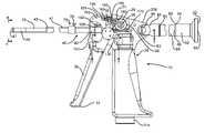
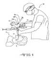
- FIG. 1illustrates an environmental perspective view of an endotracheal intubation device 10 according to the present invention in use.
- FIG. 2illustrates an environmental perspective view of an endotracheal intubation device 10 inserted into an endotracheal tube E prior to use.
- FIG. 3illustrates a side cross-sectional view of the endotracheal intubation device 10 with a cover 135 removed.
- FIG. 3Ais a cross-sectional view of an endotracheal tube stop.
- FIG. 4illustrates a distal end view of the tubular element 40 taken along line 4 - 4 of FIG. 3 .
- FIG. 5illustrates a cross-sectional view of the endotracheal intubation device 10 taken along line 5 - 5 of FIG. 2 .
- FIG. 6illustrates a magnified cross-sectional view of the curvable means of the tubular element 40 of FIG. 5 .
- FIG. 7illustrates a top cross-sectional view of the endotracheal intubation device 10 taken along line 7 - 7 of FIG. 3 .
- FIG. 8illustrates a partial cross-sectional view of the endotracheal intubation device 10 taken along line 3 - 3 of FIG. 2 .
- FIG. 8Aillustrates a magnified cross-sectional view of the handgrip of FIG. 5 .
- FIG. 9illustrates a perspective view of a second end 60 C of a vertebra mount 60 .
- FIG. 10illustrates a perspective view of a proximal end 61 A of a vertebra 61 .
- FIG. 11illustrates a perspective view of a distal end 61 A of two of the vertebra 61 which are attached to form a hinge joint.
- FIG. 12illustrates a perspective view of the yoke portion 155 of the device 10 .
- FIG. 13illustrates a perspective view of a second embodiment an endotracheal intubation device 110 according to the present invention having a video system.
- proximalrefers to a direction towards a medical professional when the endotracheal intubation device is in use.
- distalrefers to a direction towards a patient who is to be endotracheally intubated when the endotracheal intubation device is in use.
- toprefers to a direction or side, respectively of the device corresponding to the top side of the handgrip.
- belowrefers to a direction or side, respectively, of the device corresponding to the bottom side of the handgrip.
- leftrefers to a side of the device corresponding to the left side of the handgrip.
- the term “right” as used hereinrefers to a side of the device corresponding to the right side of the handgrip.
- curvable meansrefers to a part of the tubular element which is curvable.
- the curvable meanscan be provided as a series of vertebra as in the embodiment described herein, however it is not limited to this structure.
- the curvable meanscan also be provided as a bellows or other tubular structures that can be curved which are known in the art.
- pulley meansrefers to any apparatus known in the art for translating force which comprises one or more pulleys.
- Ring elementsrefers to any set of ring shaped structures, that when arranged in a series can be curved. Ring elements can be of a structure including, but not limited to, the vertebra as described herein.
- viewing meansrefers to any mechanism or device for collecting an image of the throat of the patient at the distal end of the tubular element during the endotracheal intubation procedure.
- An example of a viewing meansincludes, but is not limited to, a small video camera or a lens for a fiber optics system.
- display meansrefers to any mechanism or device for displaying an image of the throat of the patient at the distal end of the tubular element during the endotracheal intubation procedure.
- An example of a display meansincludes, but is not limited to, a liquid crystal display or other type of video display or one or more lenses which collect an image from a fiber optics system.
- transmission meansrefers to a any mechanism or device for transmitting an image of the throat from the viewing means to the display means.
- An example of a transmission meansincludes, but is not limited to, electrical wiring lines, fiber optic lines, and/or optical lenses.
- FIGS. 1 to 12One embodiment of the present invention is illustrated in the FIGS. 1 to 12 .
- This embodiment of the endotracheal intubation device 10is illustrated in use in FIGS. 1 and 2 .
- FIG. 1shows how a tubular element 40 of the endotracheal intubation device 10 can be inserted into a patient P by a medical practitioner M.
- the endotracheal intubation device 10is gripped by the medical professional M on a handgrip 20 having a top 20 A, a bottom 20 B, a left 20 C, a right 20 D (see FIG. 7 ), a front 20 E and a back 20 F.
- the fingers of the medical professionalgrip a trigger 30 which is pivotably mounted on the handgrip 20 .
- the trigger 30has a first end 31 for controlled movement when the medical professional M squeezes the trigger 30 towards the handgrip 20 .
- a curvable portion 70FIGS. 1 , 2 , 3 , 5 , 6 , 7 and 8 ) towards the distal end of the tubular element 40 is curved into a generally curved configuration in a controlled manner from a fully straight configuration.
- the medical professionalcan thereby move the distal end 47 of the tubular element 40 to safely advance the tubular element 40 into the throat of the patient.
- the endotracheal intubation device 10is well sealed so that bodily fluids cannot penetrate the device 10 and damage any internal components.
- FIG. 2illustrates how an endotracheal tube E is inserted over the tubular element 40 of the endotracheal intubation device 10 to a stop 75 ( FIGS. 1 , 2 and 3 A) prior to using the device 10 to endotracheally intubate the patient.
- the tubular element 40attaches at a proximal end 42 ( FIGS. 2 , 3 , 5 , 8 and 8 A) of a proximal portion 41 ( FIG. 2 ) of the tubular element 40 at the front 20 E of the handgrip 20 and extends to a distal end 47 of a distal portion 45 ( FIG. 2 ) which is inserted into the patient's throat to place the endotracheal tube E in the patient.
- a pivotable optics portion 80is attached to the back 20 F of the handgrip 20 on an eyepiece swivel 84 (see FIG. 3 ) at the distal end 83 of the optics portion 80 .
- An eyepiece tube 88projects from a proximal end 85 ( FIG. 5 ) of the eyepiece swivel 84 .
- an eyepiece housing 92which is mounted over the proximal end 89 of the eyepiece tube 88 .
- the medical practitioner Mcan look into the proximal end 82 of the optics portion 80 to view an image of the patient's throat as the distal end of the tubular element 40 is advanced to place the endotracheal tube E in the trachea of the patient P. Since the endotracheal intubation device 10 incorporates internal optics, it can be used in situations where an external imaging device, such as a nasopharyngoscope, is not readily available.
- FIGS. 3 through 12illustrate the internal workings of the endotracheal intubation device 10 in detail.
- the handgrip 20provides a housing 101 having an inner wall 102 which defines a lighting cavity 103 towards the bottom of the device 10 .
- the lighting cavity 103encloses a cylindrical battery sleeve 105 constructed of brass or other conducting material, having a top end 105 A and a bottom end 105 B.
- the battery sleeve 105( FIG. 5 ) is disposed against an inner wall 102 of the housing 101 towards the bottom 20 B of the handgrip 20 .
- Two batteries 120 A, 120 Bare arranged in series within the battery sleeve 105 in the lighting cavity 103 of the handgrip 20 .
- the two batteries 120 A, 120 Bare held in the lighting cavity 103 by a battery plug 114 mounted below the two batteries 120 A, 120 B at the bottom 20 B of the handgrip 20 .
- the battery plug 114has a first portion 114 A which can be gripped when inserting the battery plug 114 into the lighting cavity 103 after insertion of the two batteries 120 A, 120 B.
- a battery plug o-ring 116surrounds a second portion 114 B in the center of the battery plug 114 and rests snugly against the inner wall 102 of the housing 101 of the handgrip 20 when the battery plug 114 is inserted.
- the battery plug 114has a third portion 114 C with a thread 115 which is screwed into a threaded portion 104 in the inner wall 102 of the lighting cavity 103 . Since the battery plug o-ring 116 fits snugly against the inner wall 102 , the battery plug 114 will not loosen when the device 10 is in use. The battery plug o-ring 116 also keeps fluid out of the device 10 .
- a contact cap 119fits into a depression in the third portion 114 C of the battery plug 114 .
- a spring 117which is disposed over a projection 118 in the contact cap 119 is held against a negative terminal of a first battery 120 A to make electrical contact and support the two batteries 120 A, 120 B in the lighting cavity 103 .
- a lamp housing 106( FIG. 5 ).
- a lamp 107which is the light source for the endotracheal intubation device 10 .
- the lamp 107can be a xenon lamp or other similar light source.
- the lamp 107is affixed to a first end 108 A of a lamp base 108 .
- the lamp housing 106surrounds the first end 108 A of the lamp base 108 to enclose the lamp 107 .
- the second end 108 B of the lamp base 108rests in the top end 105 A of the battery sleeve 105 .
- At the second end 108 B of the lamp base 108is a first electrical contact 109 which is surrounded with an insulator ring 112 .
- the insulator ring 112secures the lamp base 108 in the battery sleeve 105 while also isolating the first contact 109 from electrical connection with the battery sleeve 105 .
- a second contact 110 on the lamp base 108extends above the insulator ring 112 and makes electrical contact with the battery sleeve 105 .
- the lamp housing 106is penetrated above towards the top 20 A and front 20 E of the handgrip 20 by a fiber ferrule 121 into which the proximal ends of three illumination fibers 122 ( FIG. 8A ) are secured.
- the illumination fibers 122( FIG. 8A ) are held by the fiber ferrule 121 in close proximity to the lamp 107 ( FIG. 5 ), so that the illumination fibers 122 can collect the light from the lamp 107 when it is powered by the two batteries 120 A, 120 B.
- the lamp 107can be activated by turning the battery plug 114 ( FIG.
- the lamp 107when supplied with power, emits light into a first end 121 A ( FIG. 8A ) of the fiber ferrule 121 , where the light is collected by the proximal ends of the three illumination fibers 122 .
- the second end 121 B ( FIG. 8A ) of the fiber ferrule 121protrudes out from the lamp housing 106 and into a connecting cavity 130 ( FIGS.
- the connecting cavity 130extends from the lighting cavity 103 into a lever cavity 150 ( FIGS. 3 , 5 , 8 and 8 A) which is above and distal to the lighting cavity 103 .
- a transparent window 21is mounted in an opening that penetrates the left side 20 C of the handgrip 20 and the lamp housing 106 over the lamp 107 . When the lamp 107 is turned on the transparent window 21 is lit as a reminder that the power is on.
- the lever cavity 150is enclosed by the housing 101 on the right side and the cover 135 ( FIG. 7 ) on the left side.
- the cover 135is attached to the housing 101 by a front screw 136 ( FIGS. 2 and 3 ) at a front of the cover 135 and a left pivot screw 98 ( FIG. 2 ) at a back of the cover 135 .
- the trigger 30which is mounted on the handgrip 20 has a first end 31 for controlling the degree of bend of the curvable portion 70 of the tubular element 40 when the trigger 30 is squeezed towards the handgrip 20 .
- the first end 31 ( FIG. 2 ) of the trigger 30is mounted to a pivot portion 33 of the second end 32 ( FIG.
- the pivot portion 33 of the trigger 30extends laterally left to right across the handgrip 20 .
- the pivot portion 33extends from a left mounting post 34 which is rotatably mounted in a left mounting hole 137 in the cover at the left side of the handgrip 20 , to a right mounting post 35 rotatably mounted in a right mounting hole 23 in the inner wall at the right side 20 D of the handgrip 20 .
- a pivot o-ring 36fits around the left mounting post 34 between the pivot portion 33 and rests in a groove 138 surrounding the left mounting hole 137 .
- a hinge portion 31 A on the first end 31 of the trigger 30is mounted in a trigger mounting hole 139 in the cover 135 which extends through the cover 135 to the left mounting hole 137 .
- a trigger pivot pin 140penetrates a first pivot pin hole 141 through the hinge portion 31 A of the first end 31 of the trigger 30 and a second pivot pin hole 34 A in the left mounting post 34 of the pivot portion 33 to secure the first end 31 of the trigger 30 to the pivot portion 33 .
- An elongate yoke portion 155seen in FIG.
- a pivot channel 37extends through the second end 32 of the trigger 30 from front to back which provides access between the lighting cavity 103 and the lever cavity 150 .
- a mounting channel 160extends a length through the housing 101 and the cover 135 ( FIG. 7 ) of the handgrip 20 .
- the mounting channel 160extends from the front side of the handgrip 20 to the bottom of the lever cavity 150 adjacent to the pivot channel 37 in the second end 32 of the trigger 30 .
- Mounted flush with the wall defining the mounting channel 160 and extending the length of the mounting channel 160is a tubular mounting shaft 161 .
- the mounting shaft 161is anchored in the handgrip 20 by means of a central rim 162 ( FIGS. 8 and 8A ) which encircles the mounting shaft 161 and fits into a slot 24 ( FIGS.
- an adjustable endotracheal tube stop 75as shown in FIGS. 3 and 3A encircles the proximal portion 41 of the tubular element 40 .
- the endotracheal tube stop 75has a first end 75 A ( FIG.
- FIG. 3Ahaving a first circular opening 75 C with a diameter adapted to receive an end of a standard adapter 77 on an endotracheal tube E as illustrated in FIG. 3A .
- a stop 75grips the end of the endotracheal tube in the first opening 75 C, so that it will not slide off during the intubation procedure.
- a second opening 75 B of the endotracheal tube stop 75is a second opening 75 D having a diameter fits over the tubular element 40 .
- the endotracheal tube stop 75is secured in place on the proximal portion 41 by means of a stop screw 76 .
- An internal channel 44 ( FIG. 8A ) in the tubular element 40extends the length of the tubular element 40 from the proximal end 42 which opens into the lever cavity 150 adjacent to the pivot channel 37 , through the proximal portion 41 of the tubular element 40 , the curvable portion 70 ( FIGS. 1 , 2 , 3 , 5 , 6 , 7 and 8 ), and through the distal portion 45 to the distal end 47 ( FIG. 6 ) of the tubular element 40 where a distal head 48 is inserted to cap the internal channel at distal end 47 .
- the three illumination fibers 122FIG.
- the three illumination fibers 122extend through the connecting cavity 130 , the pivot channel 37 , the lever cavity 150 and into the proximal end 42 of the internal channel 44 , where they extend to the distal end 47 of the distal portion 45 of the tubular element 40 and through the distal head 48 where they terminate at the distal ends 122 B, 123 B, 124 B as illustrated in FIG. 4 .
- the battery plug 114is turned to complete the circuit and provide power to the lamp 107 , the throat of the patient is illuminated with light from the distal ends 122 B, 123 B, 124 B of the three illumination fibers 122 .
- the distal portion 45 of the tubular element 40has an adapter 55 which fits in the proximal end 46 to attach it to the curvable portion 70 .
- the distal head 48inserts into the distal end 47 of the distal portion 45 of the tubular element 40 .
- a tube 56( FIG. 6 ) extends from the distal head 48 inside of the distal portion 45 to support a first end 52 of the optics fiber 50 .
- a lens 57 for the optics fiber 50is located between the distal ends 122 B, 123 B, 124 B of the three illumination fibers 122 .
- the lens 57 in the aperturehas approximately a 60° field of view.
- the optics fiber 50extends from the lens 57 ( FIGS. 4 , 5 and 6 ) at a first end 52 ( FIGS. 5 and 6 ) of the optics fiber 50 and passes through the length of the internal channel 44 ( FIGS. 5 , 6 and 8 A) to a second end 53 ( FIGS. 5 and 7 ) at the back of handgrip 20 .
- the optics fiber 50extends from the internal channel 44 ( FIGS. 5 , 6 and 8 A) of the tubular element 40 , into the lever cavity 150 ( FIGS. 3 , 5 and 8 A), through the pivot channel 37 ( FIGS. 5 , 7 , 8 , 8 A and 12 ) and into an optics channel 170 ( FIGS.
- FIG. 13An alternative embodiment of the present invention is shown in FIG. 13 which is identical to the embodiment of FIGS.
- a small video camera 220 at the distal end 230 of the device 210is wired through to a small video display 240 at the proximal end of the device 210 .
- a small video display in a proximal end of the devicecan be viewed through an opening in the eyepiece housing when the distal end of the tubular element is advanced forward during the endotracheal intubation procedure.
- an eyepiece tube 88attaches to the proximal end 85 ( FIG. 5 ) of the eyepiece swivel 84 ( FIG. 5 ) having an internal channel 91 ( FIG. 5 ) which extends from the eyepiece swivel 84 ( FIG. 5 ) to the proximal end 89 of the eyepiece tube 88 .
- a distal end 94 ( FIGS. 2 and 5 ) of an 18 mm Ortho eyepiece housing 92is threaded over the eyepiece tube 88 so that the proximal end 89 of eyepiece tube 88 rests against a lock ring 95 ( FIG. 5 ) in the eyepiece housing 92 ( FIG.
- the proximal end 93 ( FIGS. 3 and 5 ) of the eyepiece housing 92flares outward to provide a circular lip used as an eye rest.
- an opening 96 ( FIG. 5 )centrally located in a concave portion 97 ( FIG. 5 ) of the eyepiece housing 92 .
- the optics portion 80focuses light collected at the lens 57 ( FIGS. 4 and 6 ) of the optics fiber 50 by means of a series of lenses 175 , 176 , 177 ( FIG. 5 ) from light which is emitted from the second end 53 of the optics fiber 50 .
- An image of the throat of the patientcan be viewed through the opening 96 in the eyepiece housing 92 when the distal end 47 of the tubular element 40 is advanced forward during the endotracheal intubation procedure.
- the second end 53 of the optics fiber 50is enclosed within a flexible tubing 171 which can be constructed of silicone.
- the flexible tubing 171is supported at a distal end by a section of silicone tubing 172 A surrounding the flexible tubing 171 which is held by a lock ring 173 A in the back of the handgrip 20 .
- the proximal end of the flexible tubing 171is supported in the internal channel 87 of the eyepiece swivel 84 by a section of silicone tubing 172 B surrounding the flexible tubing 171 which is held by a lock ring 173 B.
- the flexible tubing 171encloses the optics fiber 50 extending from the optics channel 170 and through the internal channel 87 of the eyepiece swivel 84 so as to protect the optics fiber 50 when the optics portion 80 is moved.
- the eyepiece swivel 84is mounted at a left side on the left pivot screw 98 which penetrates the cover 135 at the back 20 F and left 20 C of the handgrip 20 .
- the eyepiece swivel 84is mounted at a right side on a right pivot screw 99 penetrating the housing 101 at the back 20 F and right 20 D of the handgrip 20 .
- FIG. 7the eyepiece swivel 84 is mounted at a left side on the left pivot screw 98 which penetrates the cover 135 at the back 20 F and left 20 C of the handgrip 20 .
- the eyepiece swivel 84is mounted at a right side on a right pivot screw 99 penetrating the housing 101 at the back 20 F and right 20
- the optics portion 80can be moved up and down with respect to the handgrip 20 although the flexible tubing 171 extends through to the proximal end 85 of the eyepiece swivel 84 .
- the second end 53 of the optics fiber 50is covered with a cover glass 174 A ( FIG. 5 ) and held by a mount 174 disposed over the distal end 171 A of the flexible tubing 171 .
- the optics fiber 50is held by the mount 174 so that an image is projected through the series of lenses 175 , 176 , 177 ( FIG. 5 ) in the eyepiece tube 88 and the eyepiece housing 92 .
- a distal lens 175is mounted in a distal magnification cell 180 and a proximal lens 176 is mounted in a proximal magnification cell 181 .
- the lenses 175 , 176 mounted in the eyepiece tubeproject light onto lenses 177 in the eyepiece housing 92 .
- the lenses 177 of the eyepiece housing 92are configured so that an image of the throat of the patient can be viewed through the opening 96 in the eyepiece housing 92 .
- the trigger 30can be squeezed to curve the curvable portion 70 to then view the vocal cords.
- FIG. 8Awhen the first end 31 of the trigger 30 is squeezed towards the handgrip 20 the pivot portion 33 and the yoke portion 155 rotate forward so as to act as a lever.
- a tension spring 156is attached at a first end 156 A ( FIGS. 8A and 12 ) to the yoke portion and at a second end 156 B to a back wall of the lever cavity 150 (See FIG. 12 ).
- the tension spring 156resists forward movement of the yoke portion 155 , and returns the yoke portion 155 backward again when pressure on the first end 31 of the trigger 30 is released.
- a left projection 155 A and a right projection 155 C of the yoke portion 155extend upwards to define a space through which a hollow cylindrical yoke swivel 190 is mounted.
- a hollow wire fitting 195is mounted inside the cylindrical yoke swivel 190 .
- a length adjacent to a second end 73 of a control wire 71is secured inside the wire fitting 195 so that the control wire 71 extends from the second end 195 B of the wire fitting 195 towards the back 20 F of the handgrip 20 .
- Two jam nuts 199are threaded and locked over an external thread on a front end 195 A of the wire fitting 195 and rest against a rim 193 at an end of the yoke swivel towards the front 20 E of the handgrip 20 .
- a left yoke pin 188penetrates a hole 155 B through the left projection 155 A of the yoke 155 , a left hole through the yoke swivel 190 , and into a left hole in the wire fitting 195 .
- a right yoke pin 189penetrates a hole 155 D through the right projection 155 C of the yoke portion 155 , a right hole through the yoke swivel 190 , and into a right hole in the wire fitting 195 .
- the left yoke pin 188 and right yoke pin 189allow the assembled pieces to swivel in the yoke portion 155 when the yoke portion 155 moves forward and backward in the level cavity 150 .
- the housing 101 and cover 135 of the handgrip 20also encloses a pulley 25 ( FIGS. 3 , 5 , 8 , 8 A and 12 ) which is mounted on a pulley pin 26 ( FIGS. 3 , 5 , 8 , 8 A and 12 ) which extends from a right side mounted in the housing 101 and a left side which is mounted in the cover 135 .
- the pulley 25fits into a pulley cavity 27 ( FIG. 8A ) located behind the lever cavity 150 .
- the control wire 71 towards the second end 73passes through a control wire hole 152 ( FIG. 8A ) in the back wall 151 of the lever cavity 150 and over a top of the pulley 25 in the pulley cavity 27 .
- the control wire 71wraps around to a bottom of the pulley 25 where the control wire 71 enters the optics channel 170 ( FIG. 8A ) beneath the pulley 25 and extends forward substantially parallel to the optics fiber 50 through the pivot channel 37 ( FIG. 8A , 12 ) and the lever cavity 150 .
- the control wire 71extends into the internal channel 44 of the tubular element 40 at the proximal end 42 of the proximal portion 41 and through the internal channel 44 of the tubular element 40 to a first end 72 ( FIG. 6 ) of the control wire 71 at a distal end 70 B of the curvable portion 70 as seen in FIG. 6 .
- the curvable portion 70is constructed so as to curve in a controlled manner. As illustrated in FIG. 6 , the curvable portion 70 is mounted on a vertebra mount 60 to a distal end 43 of the proximal portion 41 of the tubular element 40 .
- the curvable portion 70is constructed of a series of asymmetric vertebra 61 as illustrated in FIGS. 6 , 10 and 11 .
- the entire length of the curvable portion 70is covered with a protective tubing 65 such as Viton® tubing (DuPont, Wilmington, Del.) or other robust tubing material which seals the series of vertebra 61 and other internal components of the curvable portion 70 .
- a protective tubing 65such as Viton® tubing (DuPont, Wilmington, Del.) or other robust tubing material which seals the series of vertebra 61 and other internal components of the curvable portion 70 .
- the series of vertebra 61are mounted at a proximal end 70 A of the curvable portion 70 by means of the vertebra mount 60 .
- the vertebra mount 60has a cylindrical first end 60 A ( FIG. 9 ), a central rim 60 B, and a second end 60 C having an angled face 60 D.
- the cylindrical first end 60 Ahas an external radius such that the cylindrical first end 60 A snugly fits in the internal channel 44 of the tubular element 40 .
- the central rim 60 Brests against the distal end 43 of the proximal portion 41 of the tubular element 40 ( FIG. 6 ) when the vertebra mount 60 is inserted.
- the second end 60 C of the vertebra mount 60extends from the tubular element 40 to the angled face 60 D.
- a bottom of the angled face 60 Dhas two rounded projections 60 E, 60 F.
- a first rounded projection 60 Eis on a left side and a second projection 60 F is on a right side of a first wire hole 60 G which passes through the second end 60 C of the vertebra mount 60 .
- a top of the second end 60 C of the vertebra mount 60is shorter than the bottom, so that the angled face 60 D of the second end 60 C angles back at an 8° angle from a vertical line running from the top to the bottom of the device 10 .
- a second wire hole 60 Hwhich passes through the top of the second end 60 C and first end 60 A of the vertebra mount 60 through which the control wire 71 can freely pass.
- a fiber cavity 60 Ipasses longitudinally through the second end 60 C and the first end 60 A of the vertebra mount 60 .
- the fiber cavity 60 Iprovides an extension of the internal channel tubular element 40 through which the optics fiber 50 and the three illumination fibers 122 extend.
- FIGS. 6 , 10 and 11Mounted adjacent to the second end 60 C of the vertebra mount 60 is a first of the series of vertebra 61 ( FIGS. 6 , 10 and 11 ).
- Each of the vertebra 61are identical, each having a first indentation 61 C and a second indentation 61 D at a bottom side of a proximal end 61 A of the vertebra 61 .
- a first angled face 61 E ( FIG. 10 ) at the proximal end 61 A of the vertebra 61angles back at an 8° angle towards the distal end of the device 10 when mounted.
- the two indentations 61 C, 61 Dreceive the two rounded projections 60 E, 60 F of the vertebra mount to provide a hinge joint.
- the angle of the first angled face 61 E of the vertebra 61 and the angle of the angled face 60 D of the vertebra mount 60provide a wedge-shaped space 64 ( FIG. 6 ) therebetween which allows the vertebra 61 ( FIGS. 6 and 11 ) to twist upwards on the hinge joint with respect to the vertebra mount 60 .
- the distal end 61 D of the vertebra 61like the second end 60 C of the vertebra mount 60 has two rounded projections 61 G, 61 H at a bottom of the distal end 61 B.
- the second angled face 61 F at the distal end 61 Bangles back at an 8° angle from vertical towards the proximal end of the device 10 when mounted.
- Each of the vertebra 61 in the series of vertebra 61are identically shaped and mounted in a similar fashion, so that each vertebra can twist upwards on their hinge joint with respect to an its respective adjacent vertebra.
- a fiber cavity 60 Kextends longitudinally through each of the vertebra 61 in the series from the proximal end 61 A to the distal end 61 B of each vertebra 61 .
- the fiber cavity 61 K of the series of vertebra 61provide a portion of the internal channel 44 of the tubular element 40 through which the optics fiber 50 and the three illumination fibers 122 extend.
- a bottom of the first angled face 61 F of each vertebra 61has a first wire hole 61 I which opens between the two indentations 61 C, 61 D.
- the first wire hole 61 Ipasses longitudinally through to the distal end 61 B of the vertebra 61 and opens between the two rounded projections 61 G, 61 H on the second angled face 61 F.
- a proximal end 66 A of a wire rope 66( FIG. 6 ) which anchored in the first wire hole 60 G of the vertebra mount 60 .
- the wire rope 66extends out of the second end 60 C of the vertebra mount 60 and sequentially passes through the first wire hole 61 I of each vertebra 61 in the series and finally to the first vertebra 63 at the distal end of the series where it is anchored at a distal end 66 B.
- tensionbuilds in the wire rope 66 , which holds the curvable portion 70 rigid in a left/right torsion position.
- each vertebra 61In the top of each vertebra 61 ( FIGS. 6 , 10 and 11 ) is a second wire hole 61 J which passes longitudinally through the top of the vertebra 61 from the proximal end 61 A to the distal end 61 B.
- the control wire 71extends sequentially through the second wire hole 61 J ( FIGS. 6 , 10 and 11 ) of each vertebra 61 in the series.
- the second wire hole 61 Jhas a radius which allow the control wire 71 to slide freely in the second wire hole 61 J, except for in the first vertebra 63 where the control wire is secured. As illustrated in FIG. 8 and FIG.
- the second end 32 of the trigger 30acting as a lever, pulls the second end 73 of the control wire 71 around the pulley 25 so that the first end 72 of the control wire 71 pulls the first vertebra 63 of the series of vertebra 61 back towards the proximal end of the device 10 .
- the tension on the control wire 71twists the first vertebra 63 on its hinge joint back against an adjacent vertebra 61 of the series.
- Each of the vertebra 61twists on its hinge joint so as to close the wedge-shaped space 64 between the vertebra 61 which thereby curves the curvable portion 70 in a controlled manner from a fully straight configuration.
- the protective tubing 65 covering the vertebrareturns the curvable portion 70 to a straight conformation.
Landscapes
- Health & Medical Sciences (AREA)
- Life Sciences & Earth Sciences (AREA)
- Surgery (AREA)
- Veterinary Medicine (AREA)
- Public Health (AREA)
- Biomedical Technology (AREA)
- Heart & Thoracic Surgery (AREA)
- Pulmonology (AREA)
- Engineering & Computer Science (AREA)
- Animal Behavior & Ethology (AREA)
- General Health & Medical Sciences (AREA)
- Pathology (AREA)
- Optics & Photonics (AREA)
- Molecular Biology (AREA)
- Medical Informatics (AREA)
- Physics & Mathematics (AREA)
- Biophysics (AREA)
- Nuclear Medicine, Radiotherapy & Molecular Imaging (AREA)
- Radiology & Medical Imaging (AREA)
- Anesthesiology (AREA)
- Emergency Medicine (AREA)
- Hematology (AREA)
- Physiology (AREA)
- Otolaryngology (AREA)
- Endoscopes (AREA)
- Instruments For Viewing The Inside Of Hollow Bodies (AREA)
- Surgical Instruments (AREA)
Abstract
Description
Claims (16)
Priority Applications (9)
| Application Number | Priority Date | Filing Date | Title |
|---|---|---|---|
| US11/230,392US7658708B2 (en) | 2005-09-20 | 2005-09-20 | Endotracheal intubation device |
| EP06803312AEP1948275A2 (en) | 2005-09-20 | 2006-09-11 | Endotracheal intubation device |
| AU2006292753AAU2006292753B2 (en) | 2005-09-20 | 2006-09-11 | Endotracheal intubation device |
| JP2008532266AJP2009508636A (en) | 2005-09-20 | 2006-09-11 | Endotracheal intubation device |
| CA002623820ACA2623820A1 (en) | 2005-09-20 | 2006-09-11 | Endotracheal intubation device |
| CNA200680042283XACN101340942A (en) | 2005-09-20 | 2006-09-11 | Endotracheal Tube Equipment |
| PCT/US2006/035249WO2007035297A2 (en) | 2005-09-20 | 2006-09-11 | Endotracheal intubation device |
| US12/148,050US8231524B2 (en) | 2005-09-20 | 2008-04-16 | Endotracheal intubation device |
| US12/653,917US20100137687A1 (en) | 2005-09-20 | 2009-12-21 | Endotracheal intubation device |
Applications Claiming Priority (1)
| Application Number | Priority Date | Filing Date | Title |
|---|---|---|---|
| US11/230,392US7658708B2 (en) | 2005-09-20 | 2005-09-20 | Endotracheal intubation device |
Related Parent Applications (1)
| Application Number | Title | Priority Date | Filing Date |
|---|---|---|---|
| US11/514,486Continuation-In-PartUS7458375B2 (en) | 2005-09-20 | 2006-09-01 | Endotracheal intubation device |
Related Child Applications (2)
| Application Number | Title | Priority Date | Filing Date |
|---|---|---|---|
| US12/148,050Continuation-In-PartUS8231524B2 (en) | 2005-09-20 | 2008-04-16 | Endotracheal intubation device |
| US12/653,917ContinuationUS20100137687A1 (en) | 2005-09-20 | 2009-12-21 | Endotracheal intubation device |
Publications (2)
| Publication Number | Publication Date |
|---|---|
| US20070074720A1 US20070074720A1 (en) | 2007-04-05 |
| US7658708B2true US7658708B2 (en) | 2010-02-09 |
Family
ID=37889301
Family Applications (2)
| Application Number | Title | Priority Date | Filing Date |
|---|---|---|---|
| US11/230,392Expired - Fee RelatedUS7658708B2 (en) | 2005-09-20 | 2005-09-20 | Endotracheal intubation device |
| US12/653,917AbandonedUS20100137687A1 (en) | 2005-09-20 | 2009-12-21 | Endotracheal intubation device |
Family Applications After (1)
| Application Number | Title | Priority Date | Filing Date |
|---|---|---|---|
| US12/653,917AbandonedUS20100137687A1 (en) | 2005-09-20 | 2009-12-21 | Endotracheal intubation device |
Country Status (7)
| Country | Link |
|---|---|
| US (2) | US7658708B2 (en) |
| EP (1) | EP1948275A2 (en) |
| JP (1) | JP2009508636A (en) |
| CN (1) | CN101340942A (en) |
| AU (1) | AU2006292753B2 (en) |
| CA (1) | CA2623820A1 (en) |
| WO (1) | WO2007035297A2 (en) |
Cited By (32)
| Publication number | Priority date | Publication date | Assignee | Title |
|---|---|---|---|---|
| US20080236575A1 (en)* | 2007-03-29 | 2008-10-02 | Robert Michael Chuda | Intubation device with video, stylet steering, prep and storage system |
| US20090050146A1 (en)* | 2007-08-23 | 2009-02-26 | The Cleveland Clinic Foundation | Apparatus and method for intubating an airway of a patient |
| US20090146583A1 (en)* | 2007-02-28 | 2009-06-11 | Doheny Eye Institute | Portable handheld illumination system |
| US20100199999A1 (en)* | 2009-02-06 | 2010-08-12 | Vazales Brad E | Methods for cleaning endotracheal tubes |
| US20110023887A1 (en)* | 2009-02-06 | 2011-02-03 | Endoclear, Llc | Methods for tracheostomy visualization |
| US20110130632A1 (en)* | 2009-11-30 | 2011-06-02 | King Systems Corporation | Visualization Instrument |
| US20110137127A1 (en)* | 2009-12-08 | 2011-06-09 | Ai Medical Devices, Inc. | Dual screen intubation system |
| US20110196204A1 (en)* | 2010-02-11 | 2011-08-11 | Al Medical Devices, Inc. | Shape-conforming intubation device |
| US20110201882A1 (en)* | 2010-02-18 | 2011-08-18 | Ai Medical Devices, Inc. | Endotracheal tube exchanger and detachable stylet assembly therefor |
| US20130023859A1 (en)* | 2011-07-21 | 2013-01-24 | Tyco Healthcare Group Lp | Articulating Links with Middle Link Control System |
| US8652033B2 (en) | 2010-09-23 | 2014-02-18 | Karl Storz Endovision, Inc. | Video stylet with directable tip |
| US8667966B2 (en) | 2010-08-03 | 2014-03-11 | Hideo Koike | Intubating attachment and method |
| US20140275772A1 (en)* | 2007-03-29 | 2014-09-18 | Robert Michael Chuda | Intubation device with video and anatomic stylet steering |
| US9089364B2 (en) | 2010-05-13 | 2015-07-28 | Doheny Eye Institute | Self contained illuminated infusion cannula systems and methods and devices |
| US9357984B2 (en) | 2013-04-23 | 2016-06-07 | Covidien Lp | Constant value gap stabilizer for articulating links |
| US9445714B2 (en) | 2010-03-29 | 2016-09-20 | Endoclear Llc | Endotracheal tube coupling adapters |
| US9750912B2 (en) | 2011-05-04 | 2017-09-05 | The Regents Of The University Of Michigan | Intubation device |
| US9883791B2 (en) | 2013-10-08 | 2018-02-06 | Blink Device, Llc | Disposable sheath for an endotracheal intubation device |
| US9888832B2 (en) | 2010-09-24 | 2018-02-13 | Blink Device LLC | Endotracheal intubation device |
| US10004863B2 (en) | 2012-12-04 | 2018-06-26 | Endoclear Llc | Closed suction cleaning devices, systems and methods |
| US10016575B2 (en) | 2014-06-03 | 2018-07-10 | Endoclear Llc | Cleaning devices, systems and methods |
| US10149602B2 (en) | 2011-07-11 | 2018-12-11 | Ambu A/S | Endobronchial tube with integrated image sensor and a cleaning nozzle arrangement |
| US10219695B2 (en) | 2006-11-10 | 2019-03-05 | Doheny Eye Institute | Enhanced visualization illumination system |
| US10245402B2 (en) | 2011-07-11 | 2019-04-02 | Ambu A/S | Endobronchial tube with integrated image sensor |
| US10286171B2 (en) | 2016-01-07 | 2019-05-14 | Glenn P. Gardner | Endotracheal tube insertion device |
| US10335023B2 (en) | 2016-01-07 | 2019-07-02 | Glenn P. Gardner | Endotracheal tube insertion device |
| US10368726B2 (en) | 2013-03-15 | 2019-08-06 | Edward R. Perez-Lizano | Intubation device capable of bi-directional distal deflection and temporary proximal, shaping for laryngoscopy, tracheoscopy, and bronchoscopy |
| US10722322B2 (en) | 2010-03-29 | 2020-07-28 | Endoclear Llc | Distal airway cleaning devices |
| US20210145255A1 (en)* | 2019-11-20 | 2021-05-20 | Atmos Medizintechnik Gmbh & Co. Kg | Handle for Endoscope, Endoscope Having Such Handle and Method for Disposing such Handle on an Endoscope |
| US20210196915A1 (en)* | 2017-10-13 | 2021-07-01 | Industry-University Cooperation Foundation Hanyang University | Artificial intelligence-based automatic intubation device and method of operating the same |
| US20240008732A1 (en)* | 2020-08-20 | 2024-01-11 | Jiaqing Huang | Dual-visible and dual-positioning endotracheal intubation set with visual laryngoscope and visual guide core |
| US12108938B2 (en) | 2013-03-15 | 2024-10-08 | Dvl, Inc. | System and device for visualization of an enclosed space |
Families Citing this family (58)
| Publication number | Priority date | Publication date | Assignee | Title |
|---|---|---|---|---|
| US8231524B2 (en)* | 2005-09-20 | 2012-07-31 | Ai Medical Devices, Inc. | Endotracheal intubation device |
| US20070225556A1 (en)* | 2006-03-23 | 2007-09-27 | Ethicon Endo-Surgery, Inc. | Disposable endoscope devices |
| DE102006030521A1 (en) | 2006-07-01 | 2008-01-03 | Karl Storz Gmbh & Co.Kg | Method for producing an endoscope and such endoscope |
| KR100811588B1 (en)* | 2007-03-26 | 2008-03-11 | 한국화학연구원 | Auto Video Dropper |
| US20090138025A1 (en)* | 2007-05-04 | 2009-05-28 | Hansen Medical, Inc. | Apparatus systems and methods for forming a working platform of a robotic instrument system by manipulation of components having controllably rigidity |
| US20080312507A1 (en)* | 2007-06-16 | 2008-12-18 | Taehoon Kim | Apparatus and method for imaging-assisted intubation using pre-existing practitioner skill set |
| US20080308098A1 (en)* | 2007-06-18 | 2008-12-18 | Ai Medical Devices | Endotracheal intubation device |
| USD580549S1 (en)* | 2007-06-25 | 2008-11-11 | Ai Medical Devices | Endotracheal intubation device handle |
| WO2009051698A2 (en)* | 2007-10-12 | 2009-04-23 | Beth Israel Deaconess Medical Center | Catheter guided endotracheal intubation |
| US20090192350A1 (en)* | 2008-01-28 | 2009-07-30 | Mauricio Mejia | Wireless video stylet with display mounted to laryngoscope blade and method for using the same |
| US8888683B2 (en)* | 2008-01-28 | 2014-11-18 | Mauricio Mejia | Modifications in endoscope apparatus, using fluid and gas dynamics, and methods for improving visibility during endoscopy |
| US20090192355A1 (en)* | 2008-01-28 | 2009-07-30 | Mauricio Mejia | Scope for managing difficult pathways and method to improve visibility of the same |
| WO2010044862A1 (en) | 2008-10-17 | 2010-04-22 | Ai Medical Devices, Inc. | Endotracheal intubation device |
| DE102009022118A1 (en)* | 2009-05-20 | 2010-11-25 | Karl Storz Gmbh & Co. Kg | endoscope |
| US9101287B2 (en) | 2011-03-07 | 2015-08-11 | Endochoice Innovation Center Ltd. | Multi camera endoscope assembly having multiple working channels |
| US12137873B2 (en) | 2009-06-18 | 2024-11-12 | Endochoice, Inc. | Compact multi-viewing element endoscope system |
| US8926502B2 (en) | 2011-03-07 | 2015-01-06 | Endochoice, Inc. | Multi camera endoscope having a side service channel |
| US11864734B2 (en) | 2009-06-18 | 2024-01-09 | Endochoice, Inc. | Multi-camera endoscope |
| US11278190B2 (en) | 2009-06-18 | 2022-03-22 | Endochoice, Inc. | Multi-viewing element endoscope |
| US9101268B2 (en) | 2009-06-18 | 2015-08-11 | Endochoice Innovation Center Ltd. | Multi-camera endoscope |
| US11547275B2 (en) | 2009-06-18 | 2023-01-10 | Endochoice, Inc. | Compact multi-viewing element endoscope system |
| US9901244B2 (en) | 2009-06-18 | 2018-02-27 | Endochoice, Inc. | Circuit board assembly of a multiple viewing elements endoscope |
| US9713417B2 (en) | 2009-06-18 | 2017-07-25 | Endochoice, Inc. | Image capture assembly for use in a multi-viewing elements endoscope |
| US9492063B2 (en) | 2009-06-18 | 2016-11-15 | Endochoice Innovation Center Ltd. | Multi-viewing element endoscope |
| US9872609B2 (en) | 2009-06-18 | 2018-01-23 | Endochoice Innovation Center Ltd. | Multi-camera endoscope |
| WO2010146587A1 (en) | 2009-06-18 | 2010-12-23 | Peer Medical Ltd. | Multi-camera endoscope |
| US9402533B2 (en) | 2011-03-07 | 2016-08-02 | Endochoice Innovation Center Ltd. | Endoscope circuit board assembly |
| US10165929B2 (en) | 2009-06-18 | 2019-01-01 | Endochoice, Inc. | Compact multi-viewing element endoscope system |
| US9642513B2 (en) | 2009-06-18 | 2017-05-09 | Endochoice Inc. | Compact multi-viewing element endoscope system |
| US9706903B2 (en) | 2009-06-18 | 2017-07-18 | Endochoice, Inc. | Multiple viewing elements endoscope system with modular imaging units |
| US12220105B2 (en) | 2010-06-16 | 2025-02-11 | Endochoice, Inc. | Circuit board assembly of a multiple viewing elements endoscope |
| EP2618718B1 (en) | 2010-09-20 | 2020-04-15 | EndoChoice Innovation Center Ltd. | Multi-camera endoscope having fluid channels |
| US9560953B2 (en) | 2010-09-20 | 2017-02-07 | Endochoice, Inc. | Operational interface in a multi-viewing element endoscope |
| CN103403605A (en) | 2010-10-28 | 2013-11-20 | 恩多巧爱思创新中心有限公司 | Optical systems for multi-sensor endoscopes |
| US12204087B2 (en) | 2010-10-28 | 2025-01-21 | Endochoice, Inc. | Optical systems for multi-sensor endoscopes |
| US20120143064A1 (en) | 2010-11-05 | 2012-06-07 | Charles Dean Cyphery | Muscle function evaluating system |
| US11889986B2 (en) | 2010-12-09 | 2024-02-06 | Endochoice, Inc. | Flexible electronic circuit board for a multi-camera endoscope |
| US9320419B2 (en) | 2010-12-09 | 2016-04-26 | Endochoice Innovation Center Ltd. | Fluid channeling component of a multi-camera endoscope |
| CN107361721B (en) | 2010-12-09 | 2019-06-18 | 恩多巧爱思创新中心有限公司 | Flexible electronic circuit boards for multi-camera endoscopes |
| EP2672878B1 (en) | 2011-02-07 | 2017-11-22 | Endochoice Innovation Center Ltd. | Multi-element cover for a multi-camera endoscope |
| USD689607S1 (en)* | 2011-11-04 | 2013-09-10 | Medical Technologies Unlimited, Inc. | Functional capacity evaluator |
| CA2798716A1 (en) | 2011-12-13 | 2013-06-13 | Peermedical Ltd. | Removable tip endoscope |
| EP2604172B1 (en) | 2011-12-13 | 2015-08-12 | EndoChoice Innovation Center Ltd. | Rotatable connector for an endoscope |
| WO2013090619A1 (en) | 2011-12-15 | 2013-06-20 | The Board Of Trustees Of The Leland Stanford Junior University | Devices and methods for preventing tracheal aspiration |
| US20140378766A1 (en)* | 2012-03-13 | 2014-12-25 | Gentle And Tender Co., Ltd. | Endotracheal intubation assistance apparatus |
| US9560954B2 (en) | 2012-07-24 | 2017-02-07 | Endochoice, Inc. | Connector for use with endoscope |
| US9662466B2 (en) | 2013-03-15 | 2017-05-30 | Sanovas, Inc. | Imaging stylet for intubation |
| US9986899B2 (en) | 2013-03-28 | 2018-06-05 | Endochoice, Inc. | Manifold for a multiple viewing elements endoscope |
| US9993142B2 (en) | 2013-03-28 | 2018-06-12 | Endochoice, Inc. | Fluid distribution device for a multiple viewing elements endoscope |
| US10499794B2 (en) | 2013-05-09 | 2019-12-10 | Endochoice, Inc. | Operational interface in a multi-viewing element endoscope |
| US9840266B2 (en) | 2013-10-09 | 2017-12-12 | Glidemachines Llc | Apparatus and method for towing a load by a person |
| US9770194B2 (en) | 2013-11-05 | 2017-09-26 | Ciel Medical, Inc. | Devices and methods for airway measurement |
| US9833587B2 (en) | 2014-10-23 | 2017-12-05 | Cookgas, Llc | Camera tube with guide surface for intubation stylet and method of use |
| WO2018064185A1 (en)* | 2016-09-27 | 2018-04-05 | Maslow Andrew | Intubating endoscopic device |
| US20190217034A1 (en)* | 2016-09-27 | 2019-07-18 | Andrew Maslow | Intubating endoscopic device |
| CN110694156B (en)* | 2019-11-12 | 2022-03-15 | 浙江优亿医疗器械股份有限公司 | Visual Laryngeal Mask Assembly and Visualizer |
| US20230277045A1 (en)* | 2020-09-03 | 2023-09-07 | InnoMed Five, LLC | Medical device for female reproductive health and method of use |
| CN112754412B (en)* | 2021-01-11 | 2021-11-23 | 新乡市中心医院 | Cardiovascular intubation image auxiliary detection device |
Citations (31)
| Publication number | Priority date | Publication date | Assignee | Title |
|---|---|---|---|---|
| US2975785A (en) | 1957-09-26 | 1961-03-21 | Bausch & Lomb | Optical viewing instrument |
| US3091235A (en)* | 1960-06-15 | 1963-05-28 | American Optical Corp | Diagnostic instruments |
| US3162214A (en) | 1963-01-16 | 1964-12-22 | American Optical Corp | Flexible tubular structures |
| US3913568A (en)* | 1973-01-22 | 1975-10-21 | American Optical Corp | Nasopharyngoscope |
| US4236509A (en) | 1976-12-28 | 1980-12-02 | Nagashige Takahashi | Curving device in an endoscope |
| US4353358A (en)* | 1980-08-28 | 1982-10-12 | Emerson Reynolds L | Sigmoidoscope |
| US4669172A (en) | 1983-02-07 | 1987-06-02 | Circon Corporation | Method for fabrication of flexible shaft |
| US4861153A (en) | 1986-12-19 | 1989-08-29 | American Optical Corporation | Progressive addition spectacle lens |
| US4905666A (en) | 1987-03-27 | 1990-03-06 | Olympus Optical Co., Ltd. | Bending device for an endoscope |
| US4919112A (en)* | 1989-04-07 | 1990-04-24 | Schott Fiber Optics | Low-cost semi-disposable endoscope |
| US4949716A (en) | 1988-10-31 | 1990-08-21 | Medical Devices, Inc. | Nasal intubation adjunct |
| JPH05329095A (en) | 1992-06-03 | 1993-12-14 | Asahi Optical Co Ltd | Endoscope curving operating device |
| US5299562A (en)* | 1992-01-18 | 1994-04-05 | Richard Wolf Gmbh | Endoscope having a controllable distal end piece |
| US5327881A (en)* | 1993-02-26 | 1994-07-12 | Beth Israel Hospital Association | Fiberoptic intubating stylet |
| US5520222A (en) | 1989-10-13 | 1996-05-28 | Kabushiki Kaisha Machida Seisakusho | Bending device |
| US5630783A (en)* | 1995-08-11 | 1997-05-20 | Steinberg; Jeffrey | Portable cystoscope |
| US5676635A (en)* | 1995-08-30 | 1997-10-14 | Levin; Bruce | Instrument for insertion of an endotracheal tube |
| US5732871A (en)* | 1993-12-06 | 1998-03-31 | Ethicon, Inc. | Surgical stapling instrument with articulated stapling head assembly on rotatable and flexible support shaft |
| US5762613A (en)* | 1996-05-07 | 1998-06-09 | Spectrascience, Inc. | Optical biopsy forceps |
| US5846183A (en)* | 1995-06-07 | 1998-12-08 | Chilcoat; Robert T. | Articulated endoscope with specific advantages for laryngoscopy |
| US5868760A (en)* | 1994-12-07 | 1999-02-09 | Mcguckin, Jr.; James F. | Method and apparatus for endolumenally resectioning tissue |
| US5885288A (en)* | 1994-05-24 | 1999-03-23 | Endius Incorporated | Surgical instrument |
| US5944690A (en)* | 1997-03-17 | 1999-08-31 | C.R. Bard, Inc. | Slidable control mechanism for steerable catheter |
| US6004263A (en)* | 1996-03-13 | 1999-12-21 | Hihon Kohden Corporation | Endoscope with detachable operation unit and insertion unit |
| US6319195B1 (en)* | 1998-10-20 | 2001-11-20 | Nihon Kohden Corporation | Endoscope |
| US6432043B2 (en)* | 2000-07-19 | 2002-08-13 | Nihon Kohden Corporation | Endoscope |
| US6539942B2 (en) | 2001-04-19 | 2003-04-01 | Richard Schwartz | Endotracheal intubation device |
| US6929600B2 (en)* | 2001-07-24 | 2005-08-16 | Stephen D. Hill | Apparatus for intubation |
| US6979312B2 (en)* | 2001-04-12 | 2005-12-27 | Biotran Corporation, Inc. | Steerable sheath catheters |
| US20060094933A1 (en)* | 2004-11-04 | 2006-05-04 | Goldfarb Michael A | Articulated surgical probe and method for use |
| US20060155168A1 (en)* | 2005-01-10 | 2006-07-13 | Pease Alfred A | Optical snake |
Family Cites Families (13)
| Publication number | Priority date | Publication date | Assignee | Title |
|---|---|---|---|---|
| US3470876A (en)* | 1966-09-28 | 1969-10-07 | John Barchilon | Dirigible catheter |
| US5363838B1 (en)* | 1992-12-09 | 2000-03-28 | Gordon P George | Fiberoptic intubating scope with camera and lightweight portable screen and method of using same |
| US5733242A (en)* | 1996-02-07 | 1998-03-31 | Rayburn; Robert L. | Intubation system having an axially moveable memory cylinder |
| JP3309152B2 (en)* | 1996-03-13 | 2002-07-29 | 日本光電工業株式会社 | Endoscope for tracheal tube intubation |
| JP3220747B2 (en)* | 1998-11-10 | 2001-10-22 | 日本光電工業株式会社 | Endoscope for endotracheal tube intubation |
| FR2785132B1 (en)* | 1998-10-27 | 2000-12-22 | Tokendo Sarl | DISTAL COLOR CCD SENSOR VIDEOENDOSCOPIC PROBE |
| AU2632001A (en)* | 2000-01-06 | 2001-07-16 | Raymond L. Bedell | Steerable fiberoptic epidural balloon catheter and scope |
| JP2004109222A (en)* | 2002-09-13 | 2004-04-08 | Olympus Corp | Endoscope apparatus |
| JP4454956B2 (en)* | 2003-04-24 | 2010-04-21 | オリンパス株式会社 | Endoscope |
| JP2006006874A (en)* | 2004-06-23 | 2006-01-12 | Tadakazu Sakuragi | Endoscope with liquid-crystal monitor for guiding tracheal tube |
| JP3721189B1 (en)* | 2005-05-02 | 2005-11-30 | アルフレッサファーマ株式会社 | Tightening device for bone fastening cable |
| US20070175482A1 (en)* | 2006-01-27 | 2007-08-02 | Ezc Medical Llc | Apparatus for introducing an airway tube into the trachea having visualization capability and methods of use |
| JP5030441B2 (en)* | 2006-03-09 | 2012-09-19 | オリンパスメディカルシステムズ株式会社 | Endoscope device |
- 2005
- 2005-09-20USUS11/230,392patent/US7658708B2/ennot_activeExpired - Fee Related
- 2006
- 2006-09-11JPJP2008532266Apatent/JP2009508636A/enactivePending
- 2006-09-11CNCNA200680042283XApatent/CN101340942A/enactivePending
- 2006-09-11AUAU2006292753Apatent/AU2006292753B2/ennot_activeCeased
- 2006-09-11CACA002623820Apatent/CA2623820A1/ennot_activeAbandoned
- 2006-09-11WOPCT/US2006/035249patent/WO2007035297A2/enactiveApplication Filing
- 2006-09-11EPEP06803312Apatent/EP1948275A2/ennot_activeWithdrawn
- 2009
- 2009-12-21USUS12/653,917patent/US20100137687A1/ennot_activeAbandoned
Patent Citations (32)
| Publication number | Priority date | Publication date | Assignee | Title |
|---|---|---|---|---|
| US2975785A (en) | 1957-09-26 | 1961-03-21 | Bausch & Lomb | Optical viewing instrument |
| US3091235A (en)* | 1960-06-15 | 1963-05-28 | American Optical Corp | Diagnostic instruments |
| US3162214A (en) | 1963-01-16 | 1964-12-22 | American Optical Corp | Flexible tubular structures |
| US3913568A (en)* | 1973-01-22 | 1975-10-21 | American Optical Corp | Nasopharyngoscope |
| US4236509A (en) | 1976-12-28 | 1980-12-02 | Nagashige Takahashi | Curving device in an endoscope |
| US4353358A (en)* | 1980-08-28 | 1982-10-12 | Emerson Reynolds L | Sigmoidoscope |
| US4669172A (en) | 1983-02-07 | 1987-06-02 | Circon Corporation | Method for fabrication of flexible shaft |
| US4861153A (en) | 1986-12-19 | 1989-08-29 | American Optical Corporation | Progressive addition spectacle lens |
| US4905666A (en) | 1987-03-27 | 1990-03-06 | Olympus Optical Co., Ltd. | Bending device for an endoscope |
| US4949716A (en) | 1988-10-31 | 1990-08-21 | Medical Devices, Inc. | Nasal intubation adjunct |
| US4919112B1 (en)* | 1989-04-07 | 1993-12-28 | Low-cost semi-disposable endoscope | |
| US4919112A (en)* | 1989-04-07 | 1990-04-24 | Schott Fiber Optics | Low-cost semi-disposable endoscope |
| US5520222A (en) | 1989-10-13 | 1996-05-28 | Kabushiki Kaisha Machida Seisakusho | Bending device |
| US5299562A (en)* | 1992-01-18 | 1994-04-05 | Richard Wolf Gmbh | Endoscope having a controllable distal end piece |
| JPH05329095A (en) | 1992-06-03 | 1993-12-14 | Asahi Optical Co Ltd | Endoscope curving operating device |
| US5327881A (en)* | 1993-02-26 | 1994-07-12 | Beth Israel Hospital Association | Fiberoptic intubating stylet |
| US5732871A (en)* | 1993-12-06 | 1998-03-31 | Ethicon, Inc. | Surgical stapling instrument with articulated stapling head assembly on rotatable and flexible support shaft |
| US5885288A (en)* | 1994-05-24 | 1999-03-23 | Endius Incorporated | Surgical instrument |
| US5868760A (en)* | 1994-12-07 | 1999-02-09 | Mcguckin, Jr.; James F. | Method and apparatus for endolumenally resectioning tissue |
| US5846183A (en)* | 1995-06-07 | 1998-12-08 | Chilcoat; Robert T. | Articulated endoscope with specific advantages for laryngoscopy |
| US5630783A (en)* | 1995-08-11 | 1997-05-20 | Steinberg; Jeffrey | Portable cystoscope |
| US5676635A (en)* | 1995-08-30 | 1997-10-14 | Levin; Bruce | Instrument for insertion of an endotracheal tube |
| US6004263A (en)* | 1996-03-13 | 1999-12-21 | Hihon Kohden Corporation | Endoscope with detachable operation unit and insertion unit |
| US5762613A (en)* | 1996-05-07 | 1998-06-09 | Spectrascience, Inc. | Optical biopsy forceps |
| US5944690A (en)* | 1997-03-17 | 1999-08-31 | C.R. Bard, Inc. | Slidable control mechanism for steerable catheter |
| US6319195B1 (en)* | 1998-10-20 | 2001-11-20 | Nihon Kohden Corporation | Endoscope |
| US6432043B2 (en)* | 2000-07-19 | 2002-08-13 | Nihon Kohden Corporation | Endoscope |
| US6979312B2 (en)* | 2001-04-12 | 2005-12-27 | Biotran Corporation, Inc. | Steerable sheath catheters |
| US6539942B2 (en) | 2001-04-19 | 2003-04-01 | Richard Schwartz | Endotracheal intubation device |
| US6929600B2 (en)* | 2001-07-24 | 2005-08-16 | Stephen D. Hill | Apparatus for intubation |
| US20060094933A1 (en)* | 2004-11-04 | 2006-05-04 | Goldfarb Michael A | Articulated surgical probe and method for use |
| US20060155168A1 (en)* | 2005-01-10 | 2006-07-13 | Pease Alfred A | Optical snake |
Cited By (59)
| Publication number | Priority date | Publication date | Assignee | Title |
|---|---|---|---|---|
| US10219695B2 (en) | 2006-11-10 | 2019-03-05 | Doheny Eye Institute | Enhanced visualization illumination system |
| US8172834B2 (en) | 2007-02-28 | 2012-05-08 | Doheny Eye Institute | Portable handheld illumination system |
| US20090146583A1 (en)* | 2007-02-28 | 2009-06-11 | Doheny Eye Institute | Portable handheld illumination system |
| US20080236575A1 (en)* | 2007-03-29 | 2008-10-02 | Robert Michael Chuda | Intubation device with video, stylet steering, prep and storage system |
| US20140275772A1 (en)* | 2007-03-29 | 2014-09-18 | Robert Michael Chuda | Intubation device with video and anatomic stylet steering |
| US20090050146A1 (en)* | 2007-08-23 | 2009-02-26 | The Cleveland Clinic Foundation | Apparatus and method for intubating an airway of a patient |
| US9579012B2 (en) | 2009-02-06 | 2017-02-28 | Endoclear Llc | Visualized endotracheal tube placement systems |
| US8601633B2 (en) | 2009-02-06 | 2013-12-10 | Endoclear Llc | Cleaning of body-inserted medical tubes |
| US10682203B2 (en) | 2009-02-06 | 2020-06-16 | Endoclear Llc | Methods of cleaning endotracheal tubes including light treatment |
| US8157919B2 (en) | 2009-02-06 | 2012-04-17 | Endoclear, Llc | Methods for removing debris from medical tubes |
| US9855111B2 (en) | 2009-02-06 | 2018-01-02 | Endoclear Llc | Methods of removing biofilm from endotracheal tubes |
| US10441380B2 (en) | 2009-02-06 | 2019-10-15 | Endoclear Llc | Body-inserted tube cleaning |
| US8382908B2 (en) | 2009-02-06 | 2013-02-26 | Endoclear, Llc | Methods for cleaning endotracheal tubes |
| US8381345B2 (en) | 2009-02-06 | 2013-02-26 | Endoclear, Llc | Devices for cleaning endotracheal tubes |
| US8458844B2 (en) | 2009-02-06 | 2013-06-11 | Endoclear, Llc | Medical tube cleaning apparatus |
| US8468637B2 (en) | 2009-02-06 | 2013-06-25 | Endoclear Llc | Mechanically-actuated endotracheal tube cleaning device |
| US8534287B2 (en) | 2009-02-06 | 2013-09-17 | Endoclear, Llc | Methods for tracheostomy visualization |
| US20110023887A1 (en)* | 2009-02-06 | 2011-02-03 | Endoclear, Llc | Methods for tracheostomy visualization |
| US20100199999A1 (en)* | 2009-02-06 | 2010-08-12 | Vazales Brad E | Methods for cleaning endotracheal tubes |
| US9962233B2 (en) | 2009-02-06 | 2018-05-08 | Endoclear Llc | Body-inserted tube cleaning |
| US9386907B2 (en) | 2009-02-06 | 2016-07-12 | Endoclear Llc | Visualization systems and methods |
| US9907624B2 (en) | 2009-02-06 | 2018-03-06 | Endoclear Llc | Body-inserted tube cleaning with suction |
| US9095286B2 (en) | 2009-02-06 | 2015-08-04 | Endoclear Llc | Body-inserted tube cleaning |
| US9398837B2 (en) | 2009-02-06 | 2016-07-26 | Endoclear Llc | Methods for confirming placement of endotracheal tubes |
| US9332891B2 (en) | 2009-02-06 | 2016-05-10 | Endoclear Llc | Tracheostomy visualization |
| US9179831B2 (en) | 2009-11-30 | 2015-11-10 | King Systems Corporation | Visualization instrument |
| US20110130632A1 (en)* | 2009-11-30 | 2011-06-02 | King Systems Corporation | Visualization Instrument |
| US9854962B2 (en) | 2009-11-30 | 2018-01-02 | King Systems Corporation | Visualization instrument |
| US20110137127A1 (en)* | 2009-12-08 | 2011-06-09 | Ai Medical Devices, Inc. | Dual screen intubation system |
| US20110196204A1 (en)* | 2010-02-11 | 2011-08-11 | Al Medical Devices, Inc. | Shape-conforming intubation device |
| US20110201882A1 (en)* | 2010-02-18 | 2011-08-18 | Ai Medical Devices, Inc. | Endotracheal tube exchanger and detachable stylet assembly therefor |
| US9445714B2 (en) | 2010-03-29 | 2016-09-20 | Endoclear Llc | Endotracheal tube coupling adapters |
| US10722322B2 (en) | 2010-03-29 | 2020-07-28 | Endoclear Llc | Distal airway cleaning devices |
| US9089364B2 (en) | 2010-05-13 | 2015-07-28 | Doheny Eye Institute | Self contained illuminated infusion cannula systems and methods and devices |
| US8667966B2 (en) | 2010-08-03 | 2014-03-11 | Hideo Koike | Intubating attachment and method |
| US8652033B2 (en) | 2010-09-23 | 2014-02-18 | Karl Storz Endovision, Inc. | Video stylet with directable tip |
| US9888832B2 (en) | 2010-09-24 | 2018-02-13 | Blink Device LLC | Endotracheal intubation device |
| US9750912B2 (en) | 2011-05-04 | 2017-09-05 | The Regents Of The University Of Michigan | Intubation device |
| US10888679B2 (en) | 2011-07-11 | 2021-01-12 | Ambu A/S | Endobronchial tube with integrated image sensor |
| US10149602B2 (en) | 2011-07-11 | 2018-12-11 | Ambu A/S | Endobronchial tube with integrated image sensor and a cleaning nozzle arrangement |
| US10406309B2 (en) | 2011-07-11 | 2019-09-10 | Ambu A/S | Endobronchial tube with integrated image sensor and a cleaning nozzle arrangement |
| US10245402B2 (en) | 2011-07-11 | 2019-04-02 | Ambu A/S | Endobronchial tube with integrated image sensor |
| US20130023859A1 (en)* | 2011-07-21 | 2013-01-24 | Tyco Healthcare Group Lp | Articulating Links with Middle Link Control System |
| US10004863B2 (en) | 2012-12-04 | 2018-06-26 | Endoclear Llc | Closed suction cleaning devices, systems and methods |
| US10821249B2 (en) | 2012-12-04 | 2020-11-03 | Endoclear Llc | Closed suction cleaning devices, systems and methods |
| US11173266B2 (en) | 2012-12-04 | 2021-11-16 | Endoclear Llc | Closed suction cleaning devices, systems and methods |
| US12108938B2 (en) | 2013-03-15 | 2024-10-08 | Dvl, Inc. | System and device for visualization of an enclosed space |
| US11617498B2 (en) | 2013-03-15 | 2023-04-04 | Edward R. Perez-Lizano | Intubation device capable of bi-directional distal deflection and temporary proximal shaping for laryngoscopy, tracheoscopy, and bronchoscopy |
| US10368726B2 (en) | 2013-03-15 | 2019-08-06 | Edward R. Perez-Lizano | Intubation device capable of bi-directional distal deflection and temporary proximal, shaping for laryngoscopy, tracheoscopy, and bronchoscopy |
| US9357984B2 (en) | 2013-04-23 | 2016-06-07 | Covidien Lp | Constant value gap stabilizer for articulating links |
| US9883791B2 (en) | 2013-10-08 | 2018-02-06 | Blink Device, Llc | Disposable sheath for an endotracheal intubation device |
| US10016575B2 (en) | 2014-06-03 | 2018-07-10 | Endoclear Llc | Cleaning devices, systems and methods |
| US10850062B2 (en) | 2014-06-03 | 2020-12-01 | Endoclear Llc | Cleaning devices, systems and methods |
| US10286171B2 (en) | 2016-01-07 | 2019-05-14 | Glenn P. Gardner | Endotracheal tube insertion device |
| US10335023B2 (en) | 2016-01-07 | 2019-07-02 | Glenn P. Gardner | Endotracheal tube insertion device |
| US20210196915A1 (en)* | 2017-10-13 | 2021-07-01 | Industry-University Cooperation Foundation Hanyang University | Artificial intelligence-based automatic intubation device and method of operating the same |
| US20210145255A1 (en)* | 2019-11-20 | 2021-05-20 | Atmos Medizintechnik Gmbh & Co. Kg | Handle for Endoscope, Endoscope Having Such Handle and Method for Disposing such Handle on an Endoscope |
| US11647897B2 (en)* | 2019-11-20 | 2023-05-16 | Atmos Medizintechnik Gmbh & Co. Kg | Handle for endoscope, endoscope having such handle and method for disposing such handle on an endoscope |
| US20240008732A1 (en)* | 2020-08-20 | 2024-01-11 | Jiaqing Huang | Dual-visible and dual-positioning endotracheal intubation set with visual laryngoscope and visual guide core |
Also Published As
| Publication number | Publication date |
|---|---|
| WO2007035297A2 (en) | 2007-03-29 |
| CN101340942A (en) | 2009-01-07 |
| US20070074720A1 (en) | 2007-04-05 |
| AU2006292753A1 (en) | 2007-03-29 |
| JP2009508636A (en) | 2009-03-05 |
| WO2007035297A3 (en) | 2007-06-21 |
| CA2623820A1 (en) | 2007-03-29 |
| US20100137687A1 (en) | 2010-06-03 |
| AU2006292753B2 (en) | 2009-10-08 |
| EP1948275A2 (en) | 2008-07-30 |
Similar Documents
| Publication | Publication Date | Title |
|---|---|---|
| US7658708B2 (en) | Endotracheal intubation device | |
| US8231524B2 (en) | Endotracheal intubation device | |
| US7458375B2 (en) | Endotracheal intubation device | |
| US8042545B2 (en) | Endotracheal intubation and fluid delivery device | |
| US20080308098A1 (en) | Endotracheal intubation device | |
| US9888832B2 (en) | Endotracheal intubation device | |
| EP3636133B1 (en) | An articulated tip part for an endoscope | |
| US9750913B2 (en) | Endotracheal intubation device | |
| US8336541B2 (en) | Endotracheal intubation device | |
| US5327881A (en) | Fiberoptic intubating stylet | |
| CN1225229C (en) | Video rectoscope | |
| WO2007027811A2 (en) | Visualization stylet for medical device applications having self-contained power source | |
| EP3628208A1 (en) | An articulated tip part for an endoscope | |
| JP7585597B2 (en) | Laryngoscope for oral tracheal intubation | |
| CN219109394U (en) | Video soft laryngoscope |
Legal Events
| Date | Code | Title | Description |
|---|---|---|---|
| AS | Assignment | Owner name:AI MEDICAL DEVICES, INC.,MICHIGAN Free format text:ASSIGNMENT OF ASSIGNORS INTEREST;ASSIGNORS:SCHWARTZ, JOHN;SCHWARTZ, RICHARD;SIGNING DATES FROM 20060810 TO 20061030;REEL/FRAME:018656/0211 Owner name:AI MEDICAL DEVICES, INC., MICHIGAN Free format text:ASSIGNMENT OF ASSIGNORS INTEREST;ASSIGNORS:SCHWARTZ, JOHN;SCHWARTZ, RICHARD;REEL/FRAME:018656/0211;SIGNING DATES FROM 20060810 TO 20061030 | |
| STCF | Information on status: patent grant | Free format text:PATENTED CASE | |
| REMI | Maintenance fee reminder mailed | ||
| FPAY | Fee payment | Year of fee payment:4 | |
| SULP | Surcharge for late payment | ||
| FEPP | Fee payment procedure | Free format text:PAYOR NUMBER ASSIGNED (ORIGINAL EVENT CODE: ASPN); ENTITY STATUS OF PATENT OWNER: SMALL ENTITY | |
| AS | Assignment | Owner name:CENTURION MEDICAL PRODUCTS CORPORATION, MICHIGAN Free format text:ASSIGNMENT OF ASSIGNORS INTEREST;ASSIGNOR:AI MEDICAL DEVICES, INC.;REEL/FRAME:034424/0339 Effective date:20141126 | |
| FEPP | Fee payment procedure | Free format text:ENTITY STATUS SET TO UNDISCOUNTED (ORIGINAL EVENT CODE: BIG.) Free format text:7.5 YR SURCHARGE - LATE PMT W/IN 6 MO, LARGE ENTITY (ORIGINAL EVENT CODE: M1555) | |
| MAFP | Maintenance fee payment | Free format text:PAYMENT OF MAINTENANCE FEE, 8TH YEAR, LARGE ENTITY (ORIGINAL EVENT CODE: M1552) Year of fee payment:8 | |
| AS | Assignment | Owner name:BLINK DEVICE, LLC, MICHIGAN Free format text:ASSIGNMENT OF ASSIGNORS INTEREST;ASSIGNOR:CENTURION MEDICAL PRODUCTS CORPORATION;REEL/FRAME:044187/0814 Effective date:20171031 | |
| FEPP | Fee payment procedure | Free format text:ENTITY STATUS SET TO SMALL (ORIGINAL EVENT CODE: SMAL) | |
| FEPP | Fee payment procedure | Free format text:MAINTENANCE FEE REMINDER MAILED (ORIGINAL EVENT CODE: REM.); ENTITY STATUS OF PATENT OWNER: SMALL ENTITY | |
| LAPS | Lapse for failure to pay maintenance fees | Free format text:PATENT EXPIRED FOR FAILURE TO PAY MAINTENANCE FEES (ORIGINAL EVENT CODE: EXP.); ENTITY STATUS OF PATENT OWNER: SMALL ENTITY | |
| STCH | Information on status: patent discontinuation | Free format text:PATENT EXPIRED DUE TO NONPAYMENT OF MAINTENANCE FEES UNDER 37 CFR 1.362 | |
| FP | Lapsed due to failure to pay maintenance fee | Effective date:20220209 |