US7658698B2 - Variable stride exercise device with ramp - Google Patents
Variable stride exercise device with rampDownload PDFInfo
- Publication number
- US7658698B2 US7658698B2US11/832,496US83249607AUS7658698B2US 7658698 B2US7658698 B2US 7658698B2US 83249607 AUS83249607 AUS 83249607AUS 7658698 B2US7658698 B2US 7658698B2
- Authority
- US
- United States
- Prior art keywords
- foot support
- assembly
- ramp
- foot
- exercise apparatus
- Prior art date
- Legal status (The legal status is an assumption and is not a legal conclusion. Google has not performed a legal analysis and makes no representation as to the accuracy of the status listed.)
- Expired - Fee Related
Links
- 230000000712assemblyEffects0.000claimsabstractdescription161
- 238000000429assemblyMethods0.000claimsabstractdescription161
- 230000033001locomotionEffects0.000claimsdescription108
- 230000007935neutral effectEffects0.000claimsdescription20
- 230000008878couplingEffects0.000claimsdescription14
- 238000010168coupling processMethods0.000claimsdescription14
- 238000005859coupling reactionMethods0.000claimsdescription14
- 230000007246mechanismEffects0.000claimsdescription14
- 230000008859changeEffects0.000claimsdescription12
- 238000005096rolling processMethods0.000claims1
- 210000002683footAnatomy0.000description183
- 230000008901benefitEffects0.000description11
- 239000003381stabilizerSubstances0.000description8
- 208000027418Wounds and injuryDiseases0.000description6
- 210000003205muscleAnatomy0.000description6
- 230000006378damageEffects0.000description4
- 230000000694effectsEffects0.000description4
- 210000001624hipAnatomy0.000description4
- 210000003127kneeAnatomy0.000description4
- 210000003423ankleAnatomy0.000description3
- 230000009286beneficial effectEffects0.000description3
- 208000014674injuryDiseases0.000description3
- 210000002414legAnatomy0.000description3
- 230000001419dependent effectEffects0.000description2
- 230000005021gaitEffects0.000description2
- 230000036541healthEffects0.000description2
- 210000003041ligamentAnatomy0.000description2
- 230000037081physical activityEffects0.000description2
- 230000002441reversible effectEffects0.000description2
- 210000002435tendonAnatomy0.000description2
- 210000003371toeAnatomy0.000description2
- 208000025940Back injuryDiseases0.000description1
- 206010050031Muscle strainDiseases0.000description1
- 238000010521absorption reactionMethods0.000description1
- 230000003247decreasing effectEffects0.000description1
- 230000002526effect on cardiovascular systemEffects0.000description1
- 238000005516engineering processMethods0.000description1
- 230000007613environmental effectEffects0.000description1
- 238000011540hip replacementMethods0.000description1
- 238000013150knee replacementMethods0.000description1
- 230000000670limiting effectEffects0.000description1
- 238000000554physical therapyMethods0.000description1
- 230000009467reductionEffects0.000description1
- 230000002829reductive effectEffects0.000description1
- 230000002040relaxant effectEffects0.000description1
- 230000003252repetitive effectEffects0.000description1
- 230000000284resting effectEffects0.000description1
- 238000000926separation methodMethods0.000description1
- 238000001356surgical procedureMethods0.000description1
- 238000004804windingMethods0.000description1
Images


Classifications
- A—HUMAN NECESSITIES
- A63—SPORTS; GAMES; AMUSEMENTS
- A63B—APPARATUS FOR PHYSICAL TRAINING, GYMNASTICS, SWIMMING, CLIMBING, OR FENCING; BALL GAMES; TRAINING EQUIPMENT
- A63B22/00—Exercising apparatus specially adapted for conditioning the cardio-vascular system, for training agility or co-ordination of movements
- A63B22/0015—Exercising apparatus specially adapted for conditioning the cardio-vascular system, for training agility or co-ordination of movements with an adjustable movement path of the support elements
- A63B22/0023—Exercising apparatus specially adapted for conditioning the cardio-vascular system, for training agility or co-ordination of movements with an adjustable movement path of the support elements the inclination of the main axis of the movement path being adjustable, e.g. the inclination of an endless band
- A—HUMAN NECESSITIES
- A63—SPORTS; GAMES; AMUSEMENTS
- A63B—APPARATUS FOR PHYSICAL TRAINING, GYMNASTICS, SWIMMING, CLIMBING, OR FENCING; BALL GAMES; TRAINING EQUIPMENT
- A63B21/00—Exercising apparatus for developing or strengthening the muscles or joints of the body by working against a counterforce, with or without measuring devices
- A63B21/15—Arrangements for force transmissions
- A63B21/157—Ratchet-wheel links; Overrunning clutches; One-way clutches
- A—HUMAN NECESSITIES
- A63—SPORTS; GAMES; AMUSEMENTS
- A63B—APPARATUS FOR PHYSICAL TRAINING, GYMNASTICS, SWIMMING, CLIMBING, OR FENCING; BALL GAMES; TRAINING EQUIPMENT
- A63B22/00—Exercising apparatus specially adapted for conditioning the cardio-vascular system, for training agility or co-ordination of movements
- A63B22/0002—Exercising apparatus specially adapted for conditioning the cardio-vascular system, for training agility or co-ordination of movements involving an exercising of arms
- A63B22/001—Exercising apparatus specially adapted for conditioning the cardio-vascular system, for training agility or co-ordination of movements involving an exercising of arms by simultaneously exercising arms and legs, e.g. diagonally in anti-phase
- A—HUMAN NECESSITIES
- A63—SPORTS; GAMES; AMUSEMENTS
- A63B—APPARATUS FOR PHYSICAL TRAINING, GYMNASTICS, SWIMMING, CLIMBING, OR FENCING; BALL GAMES; TRAINING EQUIPMENT
- A63B22/00—Exercising apparatus specially adapted for conditioning the cardio-vascular system, for training agility or co-ordination of movements
- A63B22/0015—Exercising apparatus specially adapted for conditioning the cardio-vascular system, for training agility or co-ordination of movements with an adjustable movement path of the support elements
- A63B22/0017—Exercising apparatus specially adapted for conditioning the cardio-vascular system, for training agility or co-ordination of movements with an adjustable movement path of the support elements the adjustment being controlled by movement of the user
- A—HUMAN NECESSITIES
- A63—SPORTS; GAMES; AMUSEMENTS
- A63B—APPARATUS FOR PHYSICAL TRAINING, GYMNASTICS, SWIMMING, CLIMBING, OR FENCING; BALL GAMES; TRAINING EQUIPMENT
- A63B22/00—Exercising apparatus specially adapted for conditioning the cardio-vascular system, for training agility or co-ordination of movements
- A63B22/20—Exercising apparatus specially adapted for conditioning the cardio-vascular system, for training agility or co-ordination of movements using rollers, wheels, castors or the like, e.g. gliding means, to be moved over the floor or other surface, e.g. guide tracks, during exercising
- A63B22/201—Exercising apparatus specially adapted for conditioning the cardio-vascular system, for training agility or co-ordination of movements using rollers, wheels, castors or the like, e.g. gliding means, to be moved over the floor or other surface, e.g. guide tracks, during exercising for moving a support element in reciprocating translation, i.e. for sliding back and forth on a guide track
- A63B22/205—Exercising apparatus specially adapted for conditioning the cardio-vascular system, for training agility or co-ordination of movements using rollers, wheels, castors or the like, e.g. gliding means, to be moved over the floor or other surface, e.g. guide tracks, during exercising for moving a support element in reciprocating translation, i.e. for sliding back and forth on a guide track in a substantially vertical plane, e.g. for exercising against gravity
- A—HUMAN NECESSITIES
- A63—SPORTS; GAMES; AMUSEMENTS
- A63B—APPARATUS FOR PHYSICAL TRAINING, GYMNASTICS, SWIMMING, CLIMBING, OR FENCING; BALL GAMES; TRAINING EQUIPMENT
- A63B22/00—Exercising apparatus specially adapted for conditioning the cardio-vascular system, for training agility or co-ordination of movements
- A63B22/20—Exercising apparatus specially adapted for conditioning the cardio-vascular system, for training agility or co-ordination of movements using rollers, wheels, castors or the like, e.g. gliding means, to be moved over the floor or other surface, e.g. guide tracks, during exercising
- A63B22/201—Exercising apparatus specially adapted for conditioning the cardio-vascular system, for training agility or co-ordination of movements using rollers, wheels, castors or the like, e.g. gliding means, to be moved over the floor or other surface, e.g. guide tracks, during exercising for moving a support element in reciprocating translation, i.e. for sliding back and forth on a guide track
- A63B2022/206—Exercising apparatus specially adapted for conditioning the cardio-vascular system, for training agility or co-ordination of movements using rollers, wheels, castors or the like, e.g. gliding means, to be moved over the floor or other surface, e.g. guide tracks, during exercising for moving a support element in reciprocating translation, i.e. for sliding back and forth on a guide track on a curved path
- A—HUMAN NECESSITIES
- A63—SPORTS; GAMES; AMUSEMENTS
- A63B—APPARATUS FOR PHYSICAL TRAINING, GYMNASTICS, SWIMMING, CLIMBING, OR FENCING; BALL GAMES; TRAINING EQUIPMENT
- A63B21/00—Exercising apparatus for developing or strengthening the muscles or joints of the body by working against a counterforce, with or without measuring devices
- A63B21/22—Resisting devices with rotary bodies
- A63B21/225—Resisting devices with rotary bodies with flywheels
- A—HUMAN NECESSITIES
- A63—SPORTS; GAMES; AMUSEMENTS
- A63B—APPARATUS FOR PHYSICAL TRAINING, GYMNASTICS, SWIMMING, CLIMBING, OR FENCING; BALL GAMES; TRAINING EQUIPMENT
- A63B2225/00—Miscellaneous features of sport apparatus, devices or equipment
- A63B2225/09—Adjustable dimensions
Definitions
- the present inventionrelates to exercise equipment. More particularly, the invention relates to a non-impact exercise device with a reciprocating motion.
- the present inventionis directed to a non-impact, striding exercise device capable of a variety of exercise motions and having a variable stride length.
- the deviceincludes a framework, at least one ramp assembly, a pair of foot support assemblies, a foot location control assembly coupled to the foot support assemblies so as to provide resistance against the user's movements, and means for adjusting a maximum stride length of the foot support assemblies.
- a usermounts the exercise device by stepping onto the foot platforms and holding onto the handles. The user is able to engage in a reciprocating, striding motion by putting force into the foot platforms and/or the handles. Movement of either the handles or the foot platforms causes the foot platforms to move along an associated ramp of the ramp assembly.
- the shape of the ramp(s)dictate the path of the exercise movement that the user experiences.
- the present exercise deviceis designed so that it is easy for the user to enter into a linearly reciprocating motion without having to overcome the substantial inertia commonly experienced while reversing direction while using other reciprocating exercise devices, such as elliptical exercise devices.
- Elliptical exercise devicesoften use a crank and a heavy flywheel that combine to fix the path of the user's motion into a cycle that impels itself and makes it very difficult for the user to reverse direction.
- the present exercise deviceis designed such that the direction of the foot platform is easily reversed, slowed, or sped up with a minimal input of force from the user.
- the present inventionprovides a non-impact exercise device that allows a user to simulate the exercise movements of elliptical or stair stepper motions, in a minimal amount of space. This combines a reduction in injury potential with a total body workout capability in a single exercise device.
- the upper portion of the ramp assemblyis relatively vertical, corresponding to the movements of a stair stepper exercise, while the lower portion of the ramp assembly is relatively horizontal, corresponding more to the movements of an elliptical exercise.
- a useris easily able to work primarily at the upper end of the ramp assembly, at the lower end of the ramp assembly, or anywhere in between.
- the useris able to select their own desired stride length during an exercise routine, and change it accordingly at will without having to stop and adjust a mechanism.
- the present exercise devicemay include a foot location control assembly to aid the user in selecting and maintaining a stride within a desired portion of the ramp assembly.
- the foot location control assemblyis selectively adjustable by the user to effectively alter the upper and/or lower terminus of each foot support assembly.
- the foot location control assemblymay be positioned so as to set upper termini of the foot support assemblies so that user's stride motion is within a substantially horizontal portion of the ramp assembly.
- the foot location control assemblymay be positioned so as to force the user to work within a substantially vertical portion of the ramp assembly, or anywhere in between.
- the present exercise deviceis compact.
- the connection between the foot support assemblies, the handles, and the resistance assembliesare made via a flexible cable linkage, such that there are no rigid swinging arms or elbows.
- the connecting cablesare able to be contained within a substantially more compact exercise unit versus a swinging arm configuration that relies on connecting the upper and lower parts of the exercise machine via link arms and rods.
- this featurehelps to create an exercise device that is safer by eliminating the rigid swinging parts that have substantial momentum.
- Another advantage of the present inventionis that the user has unobstructed access to the exercise device.
- Certain exercise devices that have a reciprocal motionsuch as purely elliptical devices, are enclosed by a bulky cage that surrounds the moving parts of the exercise device.
- Other deviceshaving swinging members that arc out a large path through the operating space. Often times, such devices are only accessible through an opening in a cage-like frame assembly that surrounds the user interface of the elliptical exercise device.
- An advantage of the present exercise deviceis the ease of entry and simplicity of the design which allows a smaller footprint without having a relatively large cage-like frame assembly enclosing the moving parts of the exercise device. The lack of such a frame assembly allows the user of the exercise device to access the device from both the first and second sides as well as through the rear of the device.
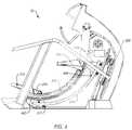
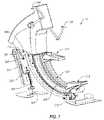
- FIG. 1is a side perspective view of an embodiment of the present invention depicting the foot platforms in a first configuration
- FIG. 2is another perspective view of the exercise device of FIG. 1 depicting the foot platforms in a second configuration
- FIG. 3is a rear view of the exercise device of FIG. 1 ;
- FIG. 4is a side view of the exercise device of FIG. 1 ;
- FIG. 5is another side view of the exercise device of FIG. 1 ;
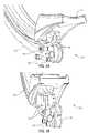
- FIGS. 5A , 5 B and 5 Care close-up views of a foot support assembly of the exercise device of FIG. 1 , for clarity, FIG. 5C does not show the spring loaded drum pulley;
- FIG. 5Dis a schematic representation of the movement of a foot support assembly upon a ramped surface of the exercise device of FIG. 1 ;
- FIG. 6is a front view of an embodiment of the exercise device of FIG. 1 depicting an embodiment of the foot location control assembly
- FIG. 6Ais a view highlighting the resistance assembly and the foot location control assembly
- FIG. 7is a perspective view depicting an embodiment of the exercise device of FIG. 1 having the spring loaded drum pulley of the foot support assemblies;
- FIG. 7Ais a perspective view depicting an embodiment of an exercise device similar to FIG. 1 , but having a series of pulleys towards the rear of the exercise device, rather than having a spring loaded drum pulley;
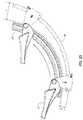
- FIG. 8is a perspective view depicting the ramp assemblies of the exercise device of FIG. 1 ;
- FIG. 9is a perspective view of an embodiment of the exercise device of FIG. 1 ; depicting the linkage assembly;
- FIG. 9Ais a close up perspective view showing several components related to the foot location control assembly of the exercise device of FIG. 1 ;
- FIGS. 10A and 10Bare schematic depictions of the variable positions of the foot location control assembly of the exercise device of FIG. 1 ;
- FIGS. 11A-11Cillustrate an alternative embodiment of the exercise device of the present invention in which cable tension within the linkage system is maintained by a lower cable and pulley assembly rather than a spring loaded drum pulley as described in previous Figures.
- the exercise device of the present inventionis a non-impact, striding exercise device that enables a variety of exercise movements.
- An exercise device 10comprises (i) a framework 100 , (ii) a pair of spaced apart ramp assemblies 200 , 202 , (iii) a pair of spaced apart foot platform assemblies 212 , 214 , (iv) a foot location control assembly 300 , (v) and a linkage assembly 400 ( FIGS. 9-10B ).
- a usermounts exercise device 10 by stepping on top of first foot support assembly 212 and second foot support assembly 214 .
- Foot platform assemblies 212 , 214roll upon a pair of spaced apart ramp assemblies 200 , 202 .
- the path that the user's feet travelis defined by first and second spaced apart foot platform assemblies 212 , 214 as they roll along respective underlying first and second ramp assemblies 212 , 214 .
- the user of exercise device 10may vary the exercise motion from a substantially elliptical motion, to a substantially stair-stepping motion.
- the usermoves spaced apart foot platform assemblies 212 , 214 in a reciprocating manner in a variety of exercise planes defined by the length and shape of spaced apart ramp assemblies 200 , 202 .
- a user's exercise stride lengthmay be all the way from very small movements (e.g., 0 to about 3 inches) to very large movements (e.g., more than 30 inches, even as high as 44 inches, for example, or more), and any increment therebetween.
- the design of ramp assemblies 200 , 202enables foot platform assemblies 212 , 214 to remain at an ergonomically favored angle throughout the user defined exercise stride.
- Framework 100supports ramp assemblies 200 , 202 , and foot location control assembly 300 all within a relatively narrow footprint. This allows easy access to exercise device 10 rather than having a “cage” surrounding the device that makes access inconvenient.
- FIGS. 1-10Brefer to embodiment 10 of the exercise device that has a reciprocally dependent movement of spaced apart handlebars 126 , 128 and spaced apart foot platform assemblies 212 , 214 .
- Spaced apart foot platform assemblies 212 , 214move upon spaced apart ramp assemblies 200 , 202 .
- a usermay define their exercise quality through foot location control assembly 300 , which is coupled with the movement of spaced apart foot assemblies 212 , 214 and spaced apart handlebars 126 , 128 , through flexible linkage assembly 400 .
- FIG. 1is a perspective view of exercise device 10 .
- Framework 100comprises a first side panel 102 (partially cut away), a second side panel 104 (cut away from FIG. 1 for clarity, shown later in FIG. 5 ), an upright gusset 106 , a bottom gusset 108 , a front stabilizer member 114 , a rear stabilizer member 116 , a first hand rest 118 , a second hand rest 120 , a first rear support 122 for supporting hand rest 118 , and a second rear support 124 for supporting hand rest 120 .
- First and second ramp assemblies 200 , 202are mounted at a front end to upright gusset 106 and at a rear end to rear stabilizer member 116 .
- First side panel 102 and second side panel 104are substantially vertical and parallel to one another.
- First side panel 102is connected at or near one end to upright gusset 106 and at or near a bottom end to bottom gusset 108 .
- Second side panel 104is attached to opposite sides of upright gusset 106 and bottom gusset 108 .
- Upright gusset 106is connected to bottom gusset 108 in an essentially perpendicular configuration.
- First guide rail 110 and second guide rail 112are bolted or otherwise fastened to the interior of first side panel 102 and second side panel 104 , respectively. As will be discussed later, first guide rail 110 and second guide rail 112 run in a substantially vertical direction, may be essentially parallel to upright gusset 106 and act to guide the movement of foot location control assembly 300 .
- Front stabilizer member 114is perpendicularly fixed to the front lower portions of first and second side panels 102 , 104 .
- Rear stabilizer member 116is perpendicularly fixed to the rear lower portions of first and second side panels 102 , 104 . Together, front and rear stabilizer members 114 , 116 , rest upon a support surface such as a floor and help to stabilize exercise device 10 .
- framework 100may contain first and second spaced apart hand rests 118 , 120 .
- the front end of first and second spaced apart hand rests 118 , 120may respectively be connected to first and second spaced apart side panels 102 , 104 .
- First and second spaced apart hand rests 118 , 120are further supported by first and second spaced apart rear supports 122 , 124 .
- a user of exercise device 10may use hand rests 118 , 120 , for example when they become fatigued from using exercise device 10 or simply as an alternative to handle bars 126 , 128 .
- a pair of additional stationary handle bars 126 a and 128 amay also be provided near and at approximately the same height as handle bars 126 , 128 (e.g. see FIG. 11A ).
- FIG. 2depicts a perspective view of exercise device 10 with foot platform assemblies 212 , 214 in an orientation opposite that depicted in FIG. 1 .
- FIG. 3depicts a rear perspective view of exercise device 10 showing the easy accessibility that a user has to exercise device 10 , as well as the overall narrow profile of exercise device 10 .
- FIG. 4depicts a side perspective view of exercise device 10 showing the overall configuration of framework 100 , ramp assemblies 200 , 202 , foot platform assemblies 212 , 214 , and foot location control assembly 300 . As will be discussed later, FIG. 4 also depicts a front cable attachment 217 to linkage assembly 400 .
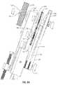
- FIG. 5depicts exercise device 10 from a side perspective, highlighting spaced apart ramp assemblies 200 , 202 and spaced apart foot platform assemblies 212 , 214 .
- Each of spaced apart ramp assemblies 200 , 202have an upper ramp 204 , 206 as well as a respective lower guide tube member 208 , 210 .
- Each upper ramp 204 , 206follow the same arc or curve.
- Each lower guide member 208 , 210follow the same arc or curve.
- Each spaced apart ramp assembly 200 , 202is attached to upright gusset 106 at a front end and to rear stabilizer member 116 at a rear end.
- Spaced apart foot platform assemblies 212 , 214each include a respective foot platform 211 , 213 and respective foot platform brackets 216 , 218 .
- Foot platforms 211 , 213are pivotally attached at their respective front ends to the top ends of respective foot platform brackets 216 , 218 .
- First and second spaced apart foot platforms 211 , 213may have an overall perpendicular orientation to respective foot platform brackets 216 , 218 when the assembly is near the lower portion of the ramp assembly, and a substantially parallel orientation relative to the associated bracket when the assembly is near the upper portion of the ramp assembly, as shown in FIG. 5 .
- FIGS. 5A , 5 B and 5 Cfurther depict the foot platform assemblies.
- Foot platform bracket 216is coupled to lower guide member 208 by foot platform bracket upper wheel 224 , which rolls along a top surface of lower guide member 208 .
- Bracket 216further includes a pair of lower wheels 228 , 230 to securely couple the foot support assembly 212 to lower guide member 208 of ramp assembly 204 .
- spaced apart foot platform brackets 216 , 218are movably fixed to roll along respective spaced apart lower guide members 208 , 210 because of the configuration of their respective first and second foot platform bracket upper wheels 224 , 226 and respective lower wheels 228 , 230 which “sandwich” respective first and second lower guide members 208 , 210 between the wheels.
- FIG. 5Ddepicts a schematic representation of the movement of a foot support assembly along a ramp assembly.
- each first and second lower guide member 208 , 210may advantageously be a different length and a different arc or curve relative to respective upper ramps 204 , 206 .
- upper ramps 204 and 206form arcs (i.e., representing a portion of a circle) having a first radius
- the lower guide members 208 and 210forming arcs having a second, different (e.g., larger) arc radius.
- ramps 204 and 206may include a curvature radius of about 31 inches
- guide members 208 and 210include a curvature radius of about 38 inches.
- each lower guide member 208 , 210is separated from its respective upper ramp 204 , 206 by a larger distance D 2 at their respective front ends than the distance D 1 of separation at their respective rear ends, as depicted in FIG. 5D .
- the top end of each foot support assembly 212 , 214travels a different path than does the bottom end of each foot support assembly 212 , 214 .
- Alternative embodimentsmay include other types of curves (e.g. an elliptical-like curve representing a portion of an ellipse, an exponential type curve, or other curve).
- this articulationresults from the movement of the bracket upwardly with respect to the foot platform 211 , and causes foot platform 211 to pivot slightly as it moves from a lower position to an upper position, but to still remain substantially parallel to a support surface.
- the amount of movement of foot platform 211can be readily adjusted as desired by adjusting the curvature of upper ramp 204 and/or lower guide member 208 .
- first and second spaced apart upper ramps 204 , 206there may be a single, continuous upper ramp instead of first and second spaced apart upper ramps 204 , 206 .
- spaced apart first and second foot platforms 211 , 213may each rest upon a single upper ramp wheel instead of each platform resting on a pair of upper ramp wheels 220 (i.e., one on either side of upper ramp 204 ).
- ramp assemblies 200 , 202may be of any arced or curved shape such that the path foot platform assemblies 212 , 214 travel along respective ramp assemblies 200 , 202 may be a range of curved shapes.
- the shapes of the curvesare dependent upon what kind of movement/workout the device is intended to deliver and/or the user wants.
- the human body's natural hip, knee and ankle movementsmay be factored into the design of ramp assemblies 200 , 202 .
- the movement of the joints throughout the stridecan be engineered to conform to the natural motion of the hips, knees and ankles such that awkward, painful and unnatural angles are avoided.
- One configurationprovides upper ramps 204 and 206 which comprise a first arc representing a portion of a circle having a first one radius, and the lower guide members 208 and 210 also comprise an arc representing a portion of a circle, but of a larger radius.
- Such a configurationhas been found to provide for a natural body motion relative to the hips, knees, and ankles during exercise.
- FIG. 4 and FIG. 5Dsuch a configuration of ramp assemblies 200 and 202 can result in an articulation of the foot platform (e.g., see foot platform 211 ) which angles the user's toes upwards near the top portion of the ramp assembly at about 1° to about 5° (e.g., 2°).
- the user's toescan be angled downward at about 5° to about 15° (e.g., 10°).
- Other articulations of the foot platforms and foot support assembliesare possible simply by altering the configuration of the upper ramps 204 , 206 and/or the lower guide members 208 , 210 , for example by changing the radii of one or both components. Changes in articulation may also be accomplished by altering the configuration of the foot platform brackets 216 , 218 which couple the foot support assemblies to the ramp assemblies.
- the movement of foot platform assemblies 212 , 214may comprise two strokes, a power stroke and a return stroke.
- the power strokeis the movement when foot platform assemblies 212 , 214 impart energy into braking device 324 , depicted in FIGS. 6 and 6A .
- the return strokeis the opposite movement and may not impart energy into braking device 324 .
- the power strokecorrelates to the downward motion of foot platform assemblies 212 , 214 .
- Braking device 324is also a flywheel, storing angular momentum as the exercise device is being used. Braking device 324 may be used as a brake in order to retard the rotation of the drive pulley assembly. Braking device 324 may be an eddy brake. In an embodiment, braking device 324 is responsible for generating the current necessary to power the display and computer of the exercise device.
- exercise device 10has a variable stride length.
- the overall stride lengthmay be varied from a barely perceptible movement all the way out to the limit of the lengths of ramp assemblies 200 , 202 .
- the stride lengthis measured along the arc length of the ramp.
- the user's stridemay be at least about 30 inches measured along the arc length of the ramp.
- the stride lengthis at least about 35 inches.
- the stride lengthis at least about 40 inches.
- the stride lengthis at least about 44 inches.
- the stride lengthcan be more.
- the length of the strideis limited by the length of ramp assemblies 200 , 202 .
- the stride lengthcan also be limited by the cabling of the resistance assembly.
- the advantages of having a large and variable range of motionwill be appreciated by any user of exercise devices. Users of different heights can determine what the comfortable range of motion is for them. A user is not limited to a “one size fits all” reciprocating device where the path of the movement is fixed.
- the infinitely variable stride lengthallows a user of any height to get a complete range of motion while using exercise device 10 .
- the foot location control assembly 300When the foot location control assembly 300 is near its middle position, the user may use the entire length of ramp assemblies 200 , 202 create a full range of motion in order to increase the difficulty of the striding motion, and for a more complete stretch of the tendons, ligaments and muscles of the legs.
- the usercan change the stride motion by changing the force put in through foot platform assemblies 212 , 214 and/or handles 126 , 128 .
- Elliptical exercise devicescommonly have a crank that fixes the motion as well as a flywheel that makes changing the direction of the motion difficult.
- the user of an elliptical deviceis typically limited to movement within the elliptical cycle of motion prescribed by the crank.
- the user of a typical elliptical devicemust overcome the substantial inertia of the flywheel in order to change direction.
- exercise device 10 of the present inventionhas linkage system 400 and foot location control assembly 300 coupled to movement of foot platform assemblies 212 , 214 along ramp assemblies 200 , 202 , the user is in control of the quality and type of exercise motion they want to experience.
- the stride length of the present exercise deviceis not predefined nor is the quality of the exercise movement unchangeable.
- FIG. 4depicts the long potential stride length relative to the overall longitudinal footprint of exercise device 10 .
- Ramp assembly length, and therefore the possible stride lengthmay be as much as around 50% of the overall length of exercise device 10 , for example.
- the amount of movement that the user experiencesis very large compared to the small lengthwise footprint of the exercise device.
- FIG. 2also depicts the narrow horizontal footprint of the exercise device.
- the present exercise deviceis narrow.
- framework 100is substantially the same width as the moving portions of exercise device 10
- the overall footprint of exercise device 10is substantially smaller than other devices on the market.
- the moving parts of the exercise deviceare within a large cage-like frame assembly that prevents the device from falling over.
- a further advantage of the current exercise deviceis that the size, and hence the footprint on the support surface, is substantially contained within the moving parts of the device, and vice versa. This decreased footprint offers substantial benefits to both the home user and the commercial user.
- the present exercise devicetakes up less space in the home of the user as well as increasing the amount of floor space available in a commercial gym that offers the present exercise device instead of other devices.
- foot platform assemblies 212 , 214 and handlebars 126 , 128can duplicate a movement that is essentially the natural gait of a walking person. While the user of the present exercise device is standing upon foot platform assemblies 212 , 214 , they may put exercise device 10 into motion by imparting a force through handlebars 126 , 128 and/or foot platform assemblies 212 , 214 . For example, when a user stands upon foot platform assemblies 212 , 214 and grabs handlebars 126 , 128 and moves their second foot in a forward direction, the first foot will move rearward, the user's first hand will move in a forward direction, and the user's second hand will move in a rearward direction. In this way, the movement of foot platform assemblies 212 , 214 and handlebars 126 , 128 may be reciprocally related to one another.
- the exercise device of the present inventionhas a movement that is reciprocating in nature, but it is not limited to the path created by a crank, nor is it inseparably tied to the momentum created by a flywheel.
- the user of the exercise deviceneed only to move their foot/hand in an opposite direction with a force commensurate with changing the movement of the foot/hand during a normal walking or running gait.
- the user of an elliptical devicemust strain to put in enough force to change the direction of rotation of the flywheel/crank/foot platform apparatus.
- the present exercise deviceoffers a non-impact, natural-gait movement and requires input forces commensurate with the natural movement of walking or running.
- the exercise device of the present inventioncontains braking device 324 (see FIGS. 6 and 6A ) that acts as a flywheel, storing momentum imparted upon it during the power stroke.
- braking device 324acts as a flywheel, storing momentum imparted upon it during the power stroke.
- force from the useris put into the exercise device by means of their weight, leg muscles and/or arm muscles.
- Braking device 324 and the drive pulley assemblyonly spin in one direction.
- Braking device 324acts as a flywheel and stores inertia in order to facilitate the start of the power stroke.
- the inertial momentum of braking device 324does not affect the minimal force necessary to change the reciprocal movement of foot platform assemblies 212 , 214 . It is only during the power stroke that braking device 324 is engaged and during which energy is imparted into braking device 324 .
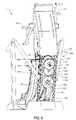
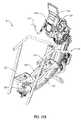
- FIGS. 6-9Aare a series of perspective views of exercise device 10 , depicting foot location control assembly 300 and linkage assembly 400 .
- FIGS. 6 and 6Aare a front perspective view of exercise device 10 depicting foot location control assembly 300 .
- Foot location control assembly 300moves along a substantially vertical plane defined by the area in between first and second guide rails 110 , 112 .
- the upper and lower limit of travel available to foot location control assembly 300are defined by the lengths of first and second guide rails 110 , 112 .
- Foot location control assembly 300includes a capstan 304 mounted to a pulley sled 302 .
- Pulley sled 302is a frame on which capstan 304 and other components are mounted, and which selectively moves up and down along guide members 110 , 112 to adjust a foot location of foot support assemblies 212 , 214 .
- Capstan 304may also be a drum pulley or other pulley or winch capable of winding or unwinding a length of cable.
- capstan 304may be coupled via a flexible linkage, such as a cable, to a resistance assembly, e.g. to a one-way clutch 312 , a first drive pulley 314 , a second drive pulley 316 , and a braking device 324 , as depicted in FIGS. 9 and 9A .
- the pulleys and capstan of foot location control assembly 300 as well as other moving parts of exercise device 10are connected to one another by a flexible linkage mechanism having components described in linkage assembly 400 .
- Foot location control assembly 300is mounted to guide rails 110 , 112 by means of a front mounting plate 326 , a rear mounting plate 328 ( FIGS. 7 , 7 A, and 9 A), a first side plate 330 , and a second side plate 332 which collectively form pulley sled 302 to which a variety of components of the foot location control assembly are mounted.
- the resistance assemblyis independently located from pulley sled 302 .
- Pulley sled 302is movably connected to first guide rail 110 on a first side through a first pair of slide bearings 334 .
- Drive pulley sled 302is movably connected to second guide rail 112 on a second side through a second pair of slide bearings 336 .
- One of slide bearings 334 and one of slide bearings 336are mounted at the top end of each side plate 330 , 332 and one of slide bearings 334 and one of slide bearings 336 are mounted at the bottom end of each side plate 330 , 332 .
- a capstan main shaft 306( FIGS. 7 , 7 A and 9 A) is mounted through rear mounting plate 328 and through rear bearing mount plate 338 ( FIG. 7 ), through front mounting plate 326 and through front bearing mount plate 338 ( FIG. 9 ).
- Capstan main shaft 306is connected to a rear end of one-way clutch 312 , which includes a pressed-in one way clutch so as to accept rotation in only one direction, and also includes a series of evenly spaced gear teeth around its circumference ( FIG. 9A ).
- First one way clutch 312is connected on its front side to a rear end of first clutch shaft 308 .
- First clutch shaft 308then ends at its front end by being mounted through first drive pulley 314 .
- Second drive pulley shaft 318is mounted through rear mounting plate 328 through lower rear bearing mount plate 340 , through front mounting plate 326 and through lower front bearing mount plate 341 . Second drive pulley shaft 318 is mounted to a second drive pulley shaft gear 343 , which includes a series of evenly spaced gear teeth that mesh with the evenly spaced teeth of first clutch gear 312 . Second drive pulley shaft 318 ends at its front end by being mounted through second drive pulley 316 .
- geared one-way clutch 312includes a pressed-in one way clutch to allow it to rotate in only one direction (e.g. counterclockwise).
- First drive pulley 314also includes a pressed-in one way clutch to allow it to rotate in only one direction, which is opposite that of geared one-way clutch 312 (e.g. clockwise).
- the teeth of geared one-way clutch 312are coupled to gear 343 , which causes gear 343 to spin in a direction opposite geared one-way clutch 312 .
- Gear 343is mounted on shaft 318 , on which is also mounted second drive pulley 316 .
- the rotational inertia from one-way clutch 312is reversed in direction by gear 343 , and then used to drive second drive pulley 316 , which in turn drives braking device 324 .
- Such a configurationdelivers all rotation inertia to braking device 324 in a single rotational direction.
- First drive pulley 314 and second drive pulley 316together form a drive assembly that drives braking device 324 . Both first drive pulley 314 and second drive pulley 316 rotate in the same direction.
- the drive assemblyimparts a one-way rotation upon a braking device shaft 322 that allows braking device 324 to spin in only one direction.
- First drive pulley v-belt 432( FIGS. 9 and 9A ) is connected at one end to first drive pulley 314 of foot location control assembly 300 and at a second end to braking device shaft 322 .
- Second drive pulley v-belt 434is connected at one end to second drive pulley 316 of foot location control assembly 300 and at a second end to braking device shaft 322 .
- a lead screw 342 , an electric motor 344 and an actuator bracket 346collectively form the actuator assembly that is responsible for moving foot location control assembly 300 .
- Lead screw 342is mounted at its bottom end to electric motor 344 .
- Lead screw 342is mounted at a position along its length to actuator bracket 346 which is mounted to rear mounting plate 328 of pulley sled 302 .
- Actuator bracket 346is threaded along its connection with lead screw 342 such that a rotation imparted upon lead screw 342 by electric motor 344 in either direction imparts an upward or downward movement of actuator bracket 346 and thus and upward or downward movement of foot location control assembly 300 as assembly 300 slides within guide rails 110 , 112 .
- Movementcould alternatively be forward/rearward, depending on the mounting orientation of the foot location control assembly.
- the location of foot support assemblies 212 , 214is moved either upwards or downwards along respective ramp assemblies 200 , 202 , as will be discussed in further detail below.
- FIG. 9is a perspective view of exercise device 10 that shows linkage assembly 400 .
- Linkage assembly 400may advantageously comprise a flexible linkage mechanism, for example, a series of pulleys and flexible links such as one or more cables that link the movement of handlebars 126 , 128 , through the foot location control assembly 300 to foot platform assemblies 212 , 214 as they move along ramp assemblies 200 , 202 .
- the term cableis meant to include other elongate flexible linkages such as belts, chains, and ropes, for example.
- Linkage assembly 400includes a first rear cable 402 and a second rear cable 404 .
- first rear cable 402is only depicted in FIG. 4 , but it is understood to be part of linkage assembly 400 , which is further depicted in FIGS. 9 , 9 A, 10 A and 10 B.
- Each of first and second rear cables 402 , 404is fixed at one end to the framework 100 (e.g., rear stabilizer 116 ).
- Each of first and second rear cables 402 , 404is fixed at an opposite end to, respectively, a spring loaded drum pulley 406 , 408 which form part of foot support assemblies 212 , 214 respectively.
- First and second spring loaded drum pulleys 406 , 408are respectively connected to first and second foot platform brackets 216 , 218 .
- first and second foot platform assemblies 212 , 214move along respective first and second ramp assemblies 200 , 202
- the length of cable wound upon first and second spring loaded drum pulleys 406 , 408changes.
- first foot support assembly 212 or second foot support assembly 214is at its maximum forward position
- the amount of wound cable upon respective first and second spring loaded drum pulleys 406 , 408is at its minimum.
- first foot support assembly 212 or second foot support assembly 214is at its maximum rearward position
- the amount of wound cable upon respective first and second spring loaded drum pulleys 406 , 408is at its maximum.
- Cables 402 , 404can provide a desired amount of tension and/or resistance to linkage assembly 400 and/or movement of foot support assemblies 212 , 214 and/or can help ensure a smooth, stable and consistent exercise motion.
- a single rear cable 466is connected to the rear end of each foot support assemblies 212 , 214 .
- Single rear cable 466is connected to the rear end of a first foot support assembly 212 , passes through a first rear transverse pulley 462 , a middle rear transverse pulley 460 , and a second rear transverse pulley 464 , then connects to the rear end of a second foot support assembly 214 .
- a first front cable 410 and a second front cable 412are attached at their respective rear ends to the front side of respective foot platform brackets 216 , 218 at the front cable attachments to each of foot platform brackets 216 , 218 .
- front cable attachment 217is depicted on foot platform bracket 218 in FIG. 4 (the respective front cable attachment for foot platform bracket 216 is not depicted).
- a first front cable 410 and a second front cable 412are attached at their respective opposite ends to a first groove 436 of a first large drive pulley 424 and a first groove 440 of a second large drive pulley 426 .
- the first end of a capstan cable 414is attached to a second groove 438 of a first large drive pulley 424 .
- Capstan cable 414is then routed through a first transverse pulley 428 that guides capstan cable 414 onto capstan 304 of foot location control assembly 300 .
- Capstan cable 414wraps around capstan 304 .
- Capstan cable 414then travels through a second transverse pulley 430 and is directed into a second groove 442 of second large drive pulley 426 , where the second end of capstan cable 414 is fixed.
- First handle bar 126is fixed to a first handle bar pulley 416 at an ergonomically beneficial angle.
- Second handle bar 128is likewise fixed to a second handle bar pulley 418 at an ergonomically beneficial angle.
- a first handle bar flexible linkagee.g. cable 420
- first handle bar pulley 416is connected at one end to first handle bar pulley 416 and at another end to first large drive pulley 424 .
- a second handle bar flexible linkagee.g., cable 422
- FIGS. 10A and 10Bdepict a schematic of the movement of capstan 304 and pulley sled 302 and the effect on the front terminus of movement of foot platform assemblies 212 , 214 .
- the effect of varying the length of unwound cable between front cables 410 , 412 and capstan cable 414is to vary the termini of travel of foot platform assemblies 212 , 214 along ramp assemblies 200 , 202 and to thereby vary the stride length of foot support assemblies 212 , 214 .
- the amount of unwound cable between front cables 410 , 412 and capstan cable 414is adjusted through the raising and lowering of foot location control assembly 300 . As depicted schematically in FIG.
- Motion of pulley sled 302either up or down adjusts the effective length of the cable so as to adjust the maximum achievable stride length of the foot support assemblies.
- the cable linkagemimics that of a shorter cable compared to if the pulley sled is positioned upward of this minimum height position.
- This adjustment feature of the pulley sled 302 , capstan 304 and the cable 414alters the effective length of the cable.
- foot location control assembly 300enables exercise device 10 to operate more like an elliptical exercise device and/or to operate more like a stair-stepper device as desired by the user.
- Foot location control assembly 300 and/or the resistance assembly described hereincan be selectively controlled, for example through the use of a user controlled console and associated electronics mounted on framework 100 .
- Foot location control assembly 300 described in conjunction with FIG. 6-10Bis an example of an adjustment assembly for adjusting the neutral body position of the user of the exercise device with respect to a support surface.
- foot location control assembly 300is an example of means for adjusting the neutral body position of the user of the exercise device with respect to a support surface.
- means for adjusting the neutral body position of a usermay comprise a foot location control assembly (e.g. a capstan 304 mounted on a pulley sled 302 and a lead screw 342 , electric motor 344 , and actuator bracket 346 as described above for assisting in moving pulley sled 302 along guide rails 110 , 112 ).
- a lead screwthat may be used independent of a pulley sled.
- Another example of means for adjusting the neutral body position of the user of the exercise device with respect to a support surfaceis an adjustable pulley system that may similarly be used independent of a lead screw that may be used to alter the orientation of the foot platforms of assemblies 212 , 214 , thereby adjusting the neutral body position of the user.
- capstan 304 and pulley 414can be configured so as that more or less of the length of cable 414 is wound around capstan 304 so as to move foot platforms of assemblies 212 , 214 upward or downward along ramps 200 , 202 , adjusting the neutral body position of the user of the exercise device relative to a support surface.
- an adjustable pulley systemmay be adjustably moveable with respect to framework 100 , such that when the pulley is moved upward or downward along the framework the position of the foot platforms of assemblies 212 , 214 move with respect to the framework 100 , thereby adjusting the neutral body position of the user of the exercise device with respect to a support surface.
- means for adjusting the neutral body position of the user of the exercise device with respect to a support surfaceinclude, but are not limited to, gear assemblies, hydraulic assemblies, an elastic resistance assemblies, and the like.
- the neutral position of the present exercise deviceis a position in which the foot platforms 211 , 213 are disposed laterally adjacent to one another (i.e., neither is “ahead” or “behind” the other).
- the user's bodyis in the neutral body position.
- the user's bodymay experience a variety of different positions depending upon how the neutral body position is adjusted. For example, changing the neutral body position may vary the muscles worked and/or intensity of the workout. Different body positions impart different characteristics to the exercise movement of the present exercise device. For example, a user may place more of a burden on their arms or legs, respectively, by adjusting the neutral body position.
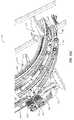
- FIGS. 11A-11Cillustrate an alternative embodiment of the exercise device of the present invention in which cable tension within the flexible linkage system may be maintained by a lower cable and pulley assembly (e.g., rather than or in addition to the spring loaded drum pulley and/or rear cable described previously).
- the embodiment illustrated in FIGS. 11A-11Cis illustrated as not including a foot location control assembly which is vertically adjustable, but rather in which the components which perform the function of the pulley sled components described in the other embodiments are fixed (i.e., not vertically adjustable so as to alter the neutral position of the foot platform assemblies).
- Such an embodimentmay be less complex and although it may not offer the full range of adjustments as the embodiments described above, such an embodiment also may have reduced cost, so as to be more suitable for home use.
- a single lower cable 350maintains tension on the cables of the flexible linkage system and on the foot platform assemblies during movement of the foot platform assemblies.
- One end of cable 350is attached to an inwardly oriented surface of bracket 218 through, for example, extension spring 352 and an associated pivoting transverse mount.
- extension spring 352aids in absorption of forces applied to the cable linkage as a result of the reciprocal movement of foot platforms 212 , 214 , as well as to minimize cable slack within the linkage system.
- the second end of cable 350is connected to bracket 216 in a similar manner.
- cable 350couples first foot support assembly 212 with second foot support assembly 214 , linking the foot platforms (e.g. 211 , 213 ) of each foot support assembly to cable 350 through brackets 216 , 218 , to which each end of cable 350 is attached.
- lower cable 350(i.e., between each end attached to brackets 216 , 218 ) is guided by a series of pulleys, which guide the cable as it runs from one bracket 218 to the other bracket 216 .
- a series of pulleyswhich guide the cable as it runs from one bracket 218 to the other bracket 216 .
- four pairs of v-groove pulleysi.e., 8 pulleys total
- Each pair of pulleysmay be mounted on a transverse shaft, which in turn may be mounted to a bracket which is attached to the frame and/or ramps 200 , 202 .
- the illustrated exampleincludes a pair of front pulleys 354 , a pair of first center pulleys 356 , a pair of second center pulleys 358 disposed rearward relative to first center pulleys 356 , and a pair of rear pulleys 360 .
- a single transverse pulley 362is mounted rearward of pulleys 360 as part of an idler assembly.
- the idler assemblyincludes pulley 362 , a mounting arm 364 and an idler spring 366 . From a first end attached to bracket 218 , cable 350 runs downward so as to contact the lower circumference of one of first center pulleys 356 , continuing downward through one of second center pulleys 358 and through one of rear pulleys 360 .
- Idler pulley 362reorients the cable 350 towards a forward direction.
- Idler pulley 362is mounted on mounting arm 364 , which is coupled to idler spring 366 .
- the idler assemblyaccounts for some variability within the cable system so as to maintain cable tension.
- bracket 216is located at a position corresponding to slightly lower than second center pulley 358
- bracket 218is illustrated at a position corresponding to a higher position on ramp 200 relative to first and second center pulleys 358 , 356 .
- cable 350does not contact all of pulleys 354 , 356 , 358 and 360 at all foot pedal positions, but only contacts those pulleys which lie downward of ramps 200 , 202 relative to the position of brackets 216 , 218 .
- cable 350does not contact either of front pulleys 354 , and cable 350 contacts only one of first center pulleys 356 and one of second center pulleys 358 . Both rear pulleys 360 are contacted by cable 350 . If either foot pedal were moved up to the extreme high end of ramps 200 , 202 , cable 350 would contact one of front pulleys 354 . As the foot pedals are reciprocally coupled, if one foot pedal were “high” the other would be “low” relative to the “high” pedal.
- Lower cable 350reciprocally relates the rearward/forward movement of each foot platform assembly to one another.
- slack within the flexible cable systemis minimized and the foot support platforms remain reciprocally linked during both the power stroke and relaxing stroke of any exercise movement.
- Lower cable 350is an example of another reciprocal coupling of the foot support assemblies, as they may also be coupled by a flexible cable linkage as described in conjunction with FIG. 9 .
- FIGS. 11A-11Cincludes components for performing the function of the foot location control assembly which are fixedly mounted to the frame of device 10 , rather than mounting the components on a pulley sled with is vertically adjustable.
- the embodiment of FIGS. 11A-11Cincludes alternative structure.
- Assembly 300 ′includes a first capstan 368 around which cable 414 is wound in one direction (e.g.
- a first drive belt 372couples first capstan 368 with breaking device 324 (e.g., an eddy current brake), while a second drive belt 374 couples second capstan 370 with breaking device 324 .
- Each capstan 368 and 370includes a one way clutch to ensure that belts 372 and 374 drive breaking device 324 in a single direction.
Landscapes
- Health & Medical Sciences (AREA)
- General Health & Medical Sciences (AREA)
- Physical Education & Sports Medicine (AREA)
- Cardiology (AREA)
- Vascular Medicine (AREA)
- Life Sciences & Earth Sciences (AREA)
- Biophysics (AREA)
- Orthopedic Medicine & Surgery (AREA)
- Rehabilitation Tools (AREA)
- Orthopedics, Nursing, And Contraception (AREA)
Abstract
Description
Claims (61)
Priority Applications (2)
| Application Number | Priority Date | Filing Date | Title |
|---|---|---|---|
| US11/832,496US7658698B2 (en) | 2006-08-02 | 2007-08-01 | Variable stride exercise device with ramp |
| PCT/US2007/075108WO2008017046A2 (en) | 2006-08-02 | 2007-08-02 | Variable stride exercise device with ramp |
Applications Claiming Priority (3)
| Application Number | Priority Date | Filing Date | Title |
|---|---|---|---|
| US83492806P | 2006-08-02 | 2006-08-02 | |
| US90891507P | 2007-03-29 | 2007-03-29 | |
| US11/832,496US7658698B2 (en) | 2006-08-02 | 2007-08-01 | Variable stride exercise device with ramp |
Publications (2)
| Publication Number | Publication Date |
|---|---|
| US20080032869A1 US20080032869A1 (en) | 2008-02-07 |
| US7658698B2true US7658698B2 (en) | 2010-02-09 |
Family
ID=38997878
Family Applications (1)
| Application Number | Title | Priority Date | Filing Date |
|---|---|---|---|
| US11/832,496Expired - Fee RelatedUS7658698B2 (en) | 2006-08-02 | 2007-08-01 | Variable stride exercise device with ramp |
Country Status (2)
| Country | Link |
|---|---|
| US (1) | US7658698B2 (en) |
| WO (1) | WO2008017046A2 (en) |
Cited By (68)
| Publication number | Priority date | Publication date | Assignee | Title |
|---|---|---|---|---|
| US20080051260A1 (en)* | 2006-08-02 | 2008-02-28 | Icon Ip, Inc. | Exercise device with pivoting assembly |
| US20100167883A1 (en)* | 2008-12-29 | 2010-07-01 | Precor Incorporated | Exercise device with adaptive curved track motion |
| US20110021325A1 (en)* | 2009-07-27 | 2011-01-27 | Enanef Limited | Exercise apparatus |
| US20140121065A1 (en)* | 2012-10-31 | 2014-05-01 | Icon Health & Fitness, Inc. | Arch Track for Elliptical Exercise Machine |
| US9174085B2 (en) | 2012-07-31 | 2015-11-03 | John Paul Foley | Exercise system and method |
| USD795974S1 (en)* | 2016-01-22 | 2017-08-29 | Nautilus, Inc. | Handle |
| USD795973S1 (en)* | 2016-01-22 | 2017-08-29 | Nautilus, Inc. | Handle for exercise machine |
| USD795975S1 (en)* | 2016-01-22 | 2017-08-29 | Nautilus, Inc. | Handle |
| US10065062B2 (en) | 2015-10-12 | 2018-09-04 | Precor Incorporated | Exercise apparatus with eddy current rail |
| US10105569B2 (en)* | 2013-09-11 | 2018-10-23 | Cybex International, Inc. | Exercise apparatus |
| US10188890B2 (en) | 2013-12-26 | 2019-01-29 | Icon Health & Fitness, Inc. | Magnetic resistance mechanism in a cable machine |
| US10252109B2 (en) | 2016-05-13 | 2019-04-09 | Icon Health & Fitness, Inc. | Weight platform treadmill |
| US10258828B2 (en) | 2015-01-16 | 2019-04-16 | Icon Health & Fitness, Inc. | Controls for an exercise device |
| US10272317B2 (en) | 2016-03-18 | 2019-04-30 | Icon Health & Fitness, Inc. | Lighted pace feature in a treadmill |
| US10279212B2 (en) | 2013-03-14 | 2019-05-07 | Icon Health & Fitness, Inc. | Strength training apparatus with flywheel and related methods |
| US10293211B2 (en) | 2016-03-18 | 2019-05-21 | Icon Health & Fitness, Inc. | Coordinated weight selection |
| US10343017B2 (en) | 2016-11-01 | 2019-07-09 | Icon Health & Fitness, Inc. | Distance sensor for console positioning |
| US10376736B2 (en) | 2016-10-12 | 2019-08-13 | Icon Health & Fitness, Inc. | Cooling an exercise device during a dive motor runway condition |
| US10426989B2 (en) | 2014-06-09 | 2019-10-01 | Icon Health & Fitness, Inc. | Cable system incorporated into a treadmill |
| US10433612B2 (en) | 2014-03-10 | 2019-10-08 | Icon Health & Fitness, Inc. | Pressure sensor to quantify work |
| US10441840B2 (en) | 2016-03-18 | 2019-10-15 | Icon Health & Fitness, Inc. | Collapsible strength exercise machine |
| US10441844B2 (en) | 2016-07-01 | 2019-10-15 | Icon Health & Fitness, Inc. | Cooling systems and methods for exercise equipment |
| US10449416B2 (en) | 2015-08-26 | 2019-10-22 | Icon Health & Fitness, Inc. | Strength exercise mechanisms |
| US10471299B2 (en) | 2016-07-01 | 2019-11-12 | Icon Health & Fitness, Inc. | Systems and methods for cooling internal exercise equipment components |
| US10493349B2 (en) | 2016-03-18 | 2019-12-03 | Icon Health & Fitness, Inc. | Display on exercise device |
| US10500473B2 (en) | 2016-10-10 | 2019-12-10 | Icon Health & Fitness, Inc. | Console positioning |
| US10518124B2 (en)* | 2018-04-08 | 2019-12-31 | Gary Lawrence Johnston | Pivoting stepper apparatus |
| US10543395B2 (en) | 2016-12-05 | 2020-01-28 | Icon Health & Fitness, Inc. | Offsetting treadmill deck weight during operation |
| US10561894B2 (en) | 2016-03-18 | 2020-02-18 | Icon Health & Fitness, Inc. | Treadmill with removable supports |
| US10625137B2 (en) | 2016-03-18 | 2020-04-21 | Icon Health & Fitness, Inc. | Coordinated displays in an exercise device |
| US10625114B2 (en) | 2016-11-01 | 2020-04-21 | Icon Health & Fitness, Inc. | Elliptical and stationary bicycle apparatus including row functionality |
| US10661114B2 (en) | 2016-11-01 | 2020-05-26 | Icon Health & Fitness, Inc. | Body weight lift mechanism on treadmill |
| US10668314B2 (en) | 2015-10-16 | 2020-06-02 | Precor Incorporated | Variable distance eddy current braking system |
| US10729965B2 (en) | 2017-12-22 | 2020-08-04 | Icon Health & Fitness, Inc. | Audible belt guide in a treadmill |
| US10786706B2 (en) | 2018-07-13 | 2020-09-29 | Icon Health & Fitness, Inc. | Cycling shoe power sensors |
| US10918905B2 (en) | 2016-10-12 | 2021-02-16 | Icon Health & Fitness, Inc. | Systems and methods for reducing runaway resistance on an exercise device |
| US10940360B2 (en) | 2015-08-26 | 2021-03-09 | Icon Health & Fitness, Inc. | Strength exercise mechanisms |
| US10953305B2 (en) | 2015-08-26 | 2021-03-23 | Icon Health & Fitness, Inc. | Strength exercise mechanisms |
| US11000730B2 (en) | 2018-03-16 | 2021-05-11 | Icon Health & Fitness, Inc. | Elliptical exercise machine |
| US11033777B1 (en) | 2019-02-12 | 2021-06-15 | Icon Health & Fitness, Inc. | Stationary exercise machine |
| US11058913B2 (en) | 2017-12-22 | 2021-07-13 | Icon Health & Fitness, Inc. | Inclinable exercise machine |
| US11058914B2 (en) | 2016-07-01 | 2021-07-13 | Icon Health & Fitness, Inc. | Cooling methods for exercise equipment |
| US11187285B2 (en) | 2017-12-09 | 2021-11-30 | Icon Health & Fitness, Inc. | Systems and methods for selectively rotationally fixing a pedaled drivetrain |
| US11185734B2 (en)* | 2018-04-08 | 2021-11-30 | Gary Lawrence Johnston | Twisting stepper apparatus |
| US11244751B2 (en) | 2012-10-19 | 2022-02-08 | Finish Time Holdings, Llc | Method and device for providing a person with training data of an athlete as the athlete is performing a swimming workout |
| US11298577B2 (en) | 2019-02-11 | 2022-04-12 | Ifit Inc. | Cable and power rack exercise machine |
| US11318342B2 (en)* | 2019-03-20 | 2022-05-03 | Paradigm Health and Wellness | Mini stepper with flat steps |
| US11326673B2 (en) | 2018-06-11 | 2022-05-10 | Ifit Inc. | Increased durability linear actuator |
| US11451108B2 (en) | 2017-08-16 | 2022-09-20 | Ifit Inc. | Systems and methods for axial impact resistance in electric motors |
| US11534651B2 (en) | 2019-08-15 | 2022-12-27 | Ifit Inc. | Adjustable dumbbell system |
| US11534654B2 (en) | 2019-01-25 | 2022-12-27 | Ifit Inc. | Systems and methods for an interactive pedaled exercise device |
| US11610664B2 (en) | 2012-07-31 | 2023-03-21 | Peloton Interactive, Inc. | Exercise system and method |
| US11673036B2 (en) | 2019-11-12 | 2023-06-13 | Ifit Inc. | Exercise storage system |
| US11794070B2 (en) | 2019-05-23 | 2023-10-24 | Ifit Inc. | Systems and methods for cooling an exercise device |
| US11850497B2 (en) | 2019-10-11 | 2023-12-26 | Ifit Inc. | Modular exercise device |
| US11878199B2 (en) | 2021-02-16 | 2024-01-23 | Ifit Inc. | Safety mechanism for an adjustable dumbbell |
| US11931621B2 (en) | 2020-03-18 | 2024-03-19 | Ifit Inc. | Systems and methods for treadmill drift avoidance |
| US11951377B2 (en) | 2020-03-24 | 2024-04-09 | Ifit Inc. | Leaderboard with irregularity flags in an exercise machine system |
| US12029961B2 (en) | 2020-03-24 | 2024-07-09 | Ifit Inc. | Flagging irregularities in user performance in an exercise machine system |
| US12029935B2 (en) | 2021-08-19 | 2024-07-09 | Ifit Inc. | Adjustment mechanism for an adjustable kettlebell |
| US12176009B2 (en) | 2021-12-30 | 2024-12-24 | Ifit Inc. | Systems and methods for synchronizing workout equipment with video files |
| US12219201B2 (en) | 2021-08-05 | 2025-02-04 | Ifit Inc. | Synchronizing video workout programs across multiple devices |
| US12263371B2 (en) | 2021-04-27 | 2025-04-01 | Ifit Inc. | Devices, systems, and methods for rotating a tread belt in two directions |
| US12280294B2 (en) | 2021-10-15 | 2025-04-22 | Ifit Inc. | Magnetic clutch for a pedaled drivetrain |
| US12350573B2 (en) | 2021-04-27 | 2025-07-08 | Ifit Inc. | Systems and methods for cross-training on exercise devices |
| US12350547B2 (en) | 2022-02-28 | 2025-07-08 | Ifit Inc. | Devices, systems, and methods for moving a movable step through a transition zone |
| US12409375B2 (en) | 2022-03-18 | 2025-09-09 | Ifit Inc. | Systems and methods for haptic simulation in incline exercise devices |
| US12433815B2 (en) | 2020-10-02 | 2025-10-07 | Ifit Inc. | Massage roller with pressure sensors |
Families Citing this family (15)
| Publication number | Priority date | Publication date | Assignee | Title |
|---|---|---|---|---|
| US9108081B2 (en)* | 2001-11-13 | 2015-08-18 | Cybex International, Inc. | Exercise apparatus |
| US7740563B2 (en)* | 2004-08-11 | 2010-06-22 | Icon Ip, Inc. | Elliptical exercise machine with integrated anaerobic exercise system |
| US7766797B2 (en)* | 2004-08-11 | 2010-08-03 | Icon Ip, Inc. | Breakaway or folding elliptical exercise machine |
| US7658698B2 (en) | 2006-08-02 | 2010-02-09 | Icon Ip, Inc. | Variable stride exercise device with ramp |
| US7736279B2 (en) | 2007-02-20 | 2010-06-15 | Icon Ip, Inc. | One-step foldable elliptical exercise machine |
| US7674205B2 (en) | 2007-05-08 | 2010-03-09 | Icon Ip, Inc. | Elliptical exercise machine with adjustable foot motion |
| US7618350B2 (en)* | 2007-06-04 | 2009-11-17 | Icon Ip, Inc. | Elliptical exercise machine with adjustable ramp |
| CN103041542A (en)* | 2012-12-20 | 2013-04-17 | 成都绿迪科技有限公司 | Body-building appliance |
| US9248338B2 (en)* | 2014-01-20 | 2016-02-02 | Dk City Corporation | Elliptical exercise machine |
| US9457224B2 (en)* | 2014-11-11 | 2016-10-04 | Cybex International, Inc. | Exercise apparatus |
| US20170203144A1 (en)* | 2016-01-14 | 2017-07-20 | Preventive Medical Health Care Co., Ltd. | Direction-reversing device and exercise equipment |
| EP3393607B1 (en) | 2016-03-25 | 2019-11-27 | Cybex International, Inc. | Exercise apparatus |
| CN106730593A (en)* | 2016-12-29 | 2017-05-31 | 广东奥玛健身器材有限公司 | Treadmills |
| CN112891830A (en)* | 2018-03-17 | 2021-06-04 | 陈科明 | Electric treadmill with vertical armrest capable of swinging |
| US11013954B2 (en)* | 2018-07-02 | 2021-05-25 | Magic by Magic, Inc. | Stationary sled exercise machine |
Citations (203)
| Publication number | Priority date | Publication date | Assignee | Title |
|---|---|---|---|---|
| FR498150A (en) | 1916-06-06 | 1919-12-30 | Pierre Joseph Amieux | Mechanotherapy device intended for the passive mobilization of the lower limbs of injured or bedridden patients |
| US3316898A (en) | 1964-10-23 | 1967-05-02 | James W Brown | Rehabilitation and exercise apparatus |
| US3501140A (en) | 1968-01-02 | 1970-03-17 | George J Eichorn | Combined collapsible physical fitness apparatus including a horizontal bar and other exercising devices |
| US3622179A (en)* | 1970-07-23 | 1971-11-23 | Winfred C Pfersick | Occupant-driven open wheel device |
| US3756595A (en) | 1971-04-23 | 1973-09-04 | G Hague | Leg exercising device for simulating ice skating |
| US3824994A (en) | 1973-01-29 | 1974-07-23 | R S Reciprocating Trainer Ente | Reciprocating walker |
| US3941377A (en) | 1974-11-19 | 1976-03-02 | Hakon Lie | Apparatus for simulated skiing |
| US4140312A (en) | 1975-11-21 | 1979-02-20 | Buchmann Rudolf Ch | Stationary exercise bicycle |
| US4300760A (en) | 1977-01-12 | 1981-11-17 | Harry Bobroff | Exercise device |
| US4340214A (en)* | 1979-06-18 | 1982-07-20 | Schuetzer Bjoern E | Training apparatus for skaters |
| US4354675A (en) | 1979-06-12 | 1982-10-19 | Global Gym & Fitness Equipment Limited | Weight lifting device |
| US4679787A (en) | 1985-02-14 | 1987-07-14 | The Stouffer Corporation | Combined exercise station and sleeping bed |
| US4708338A (en) | 1986-08-04 | 1987-11-24 | Potts Lanny L | Stair climbing exercise apparatus |
| US4720093A (en) | 1984-06-18 | 1988-01-19 | Del Mar Avionics | Stress test exercise device |
| US4938474A (en) | 1988-12-23 | 1990-07-03 | Laguna Tectrix, Inc. | Exercise apparatus and method which simulate stair climbing |
| US5013031A (en) | 1990-04-17 | 1991-05-07 | Bull John W | Exercise apparatus |
| US5039088A (en) | 1990-04-26 | 1991-08-13 | Shifferaw Tessema D | Exercise machine |
| US5078389A (en) | 1991-07-19 | 1992-01-07 | David Chen | Exercise machine with three exercise modes |
| US5135447A (en) | 1988-10-21 | 1992-08-04 | Life Fitness | Exercise apparatus for simulating stair climbing |
| US5180351A (en)* | 1991-10-21 | 1993-01-19 | Alpine Life Sports | Simulated stair climbing exercise apparatus having variable sensory feedback |
| US5195935A (en) | 1990-12-20 | 1993-03-23 | Sf Engineering | Exercise apparatus with automatic variation of provided passive and active exercise without interruption of the exercise |
| US5199931A (en)* | 1991-11-27 | 1993-04-06 | Fitness Master, Inc. | Exercise machine for simulating stair climbing |
| USD336141S (en) | 1991-08-14 | 1993-06-01 | Mikron Industries | Window component extrusion |
| US5242343A (en)* | 1992-09-30 | 1993-09-07 | Larry Miller | Stationary exercise device |
| US5267922A (en)* | 1992-07-06 | 1993-12-07 | Robinson Eldon L | Simulated stair exerciser |
| US5279529A (en) | 1992-04-16 | 1994-01-18 | Eschenbach Paul W | Programmed pedal platform exercise apparatus |
| US5279531A (en) | 1993-03-11 | 1994-01-18 | Jen Huey Chiou Ju | Foot exercising apparatus |
| USD344112S (en) | 1992-06-08 | 1994-02-08 | Smith Gary H | Physical exerciser |
| US5290211A (en) | 1992-10-29 | 1994-03-01 | Stearns Technologies, Inc. | Exercise device |
| US5299993A (en) | 1992-12-01 | 1994-04-05 | Pacific Fitness Corporation | Articulated lower body exerciser |
| US5308296A (en)* | 1992-07-16 | 1994-05-03 | Donald Eckstein | Interactive video and exercise apparatus |
| US5322491A (en) | 1992-06-23 | 1994-06-21 | Precor Incorporated | Exercise apparatus with reciprocating levers coupled by resilient linkage for semi-dependent action |
| US5336141A (en) | 1992-09-25 | 1994-08-09 | Vittone Larry W | Exercise machine for simulating perambulatory movement |
| US5352169A (en) | 1993-04-22 | 1994-10-04 | Eschenbach Paul W | Collapsible exercise machine |
| USD356128S (en) | 1993-04-20 | 1995-03-07 | Exerhealth, Inc. | Physical exerciser |
| US5415607A (en) | 1993-09-24 | 1995-05-16 | M. Michael Carpenter | Exercise device |
| US5419751A (en) | 1993-10-28 | 1995-05-30 | Stamina Products, Inc. | Multi-function exercise apparatus |
| US5423729A (en) | 1994-08-01 | 1995-06-13 | Eschenbach; Paul W. | Collapsible exercise machine with arm exercise |
| US5435801A (en) | 1994-08-01 | 1995-07-25 | Hung; Michael | Multi-functional sporting equipment |
| US5435799A (en) | 1993-06-24 | 1995-07-25 | Physiq, Inc. | Circuit training exercise apparatus |
| USD367689S (en) | 1995-04-11 | 1996-03-05 | Exerhealth, Inc. | Exercise machine |
| US5518473A (en)* | 1995-03-20 | 1996-05-21 | Miller; Larry | Exercise device |
| US5527245A (en) | 1994-02-03 | 1996-06-18 | Icon Health & Fitness, Inc. | Aerobic and anaerobic exercise machine |
| US5527246A (en) | 1995-01-25 | 1996-06-18 | Rodgers, Jr.; Robert E. | Mobile exercise apparatus |
| US5529555A (en) | 1995-06-06 | 1996-06-25 | Ccs, Llc | Crank assembly for an exercising device |
| US5529554A (en) | 1993-04-22 | 1996-06-25 | Eschenbach; Paul W. | Collapsible exercise machine with multi-mode operation |
| US5540637A (en) | 1995-01-25 | 1996-07-30 | Ccs, Llc | Stationary exercise apparatus having a preferred foot platform orientation |
| US5549526A (en) | 1995-01-25 | 1996-08-27 | Ccs, Llc | Stationary exercise apparatus |
| US5562574A (en)* | 1996-02-08 | 1996-10-08 | Miller; Larry | Compact exercise device |
| US5573480A (en) | 1995-01-25 | 1996-11-12 | Ccs, Llc | Stationary exercise apparatus |
| US5577985A (en) | 1996-02-08 | 1996-11-26 | Miller; Larry | Stationary exercise device |
| US5591107A (en)* | 1995-01-25 | 1997-01-07 | Rodgers, Jr.; Robert E. | Mobile exercise apparatus |
| US5593372A (en) | 1995-01-25 | 1997-01-14 | Ccs, Llc | Stationary exercise apparatus having a preferred foot platform path |
| US5595556A (en) | 1992-09-30 | 1997-01-21 | Icon Health & Fitness, Inc. | Treadmill with upper body system |
| US5595553A (en) | 1995-01-25 | 1997-01-21 | Ccs, Llc | Stationary exercise apparatus |
| US5611756A (en) | 1996-02-08 | 1997-03-18 | Miller; Larry | Stationary exercise device |
| US5611758A (en) | 1996-05-15 | 1997-03-18 | Ccs, Llc | Recumbent exercise apparatus |
| US5616103A (en) | 1995-08-03 | 1997-04-01 | Lee; Kuo-Ron | Jogger exerciser |
| US5626542A (en) | 1996-01-31 | 1997-05-06 | Icon Health & Fitness, Inc. | Folding rider exerciser |
| USD380509S (en) | 1995-09-15 | 1997-07-01 | Healthrider, Inc. | Exercise machine |
| US5653662A (en) | 1996-05-24 | 1997-08-05 | Rodgers, Jr.; Robert E. | Stationary exercise apparatus |
| USD384118S (en) | 1996-03-05 | 1997-09-23 | Healthrider Corp. | Exercise machine |
| US5672140A (en) | 1996-01-30 | 1997-09-30 | Icon Health & Fitness, Inc. | Reorienting treadmill with inclination mechanism |
| US5685804A (en) | 1995-12-07 | 1997-11-11 | Precor Incorporated | Stationary exercise device |
| US5690589A (en) | 1995-01-25 | 1997-11-25 | Rodgers, Jr.; Robert E. | Stationary exercise apparatus |
| US5695435A (en) | 1995-02-01 | 1997-12-09 | Icon Health & Fitness, Inc. | Collapsible rider exerciser |
| US5707320A (en) | 1996-12-18 | 1998-01-13 | Yu; Huei-Nan | Swimming exerciser |
| US5707321A (en) | 1995-06-30 | 1998-01-13 | Maresh; Joseph Douglas | Four bar exercise machine |
| US5722922A (en) | 1991-01-23 | 1998-03-03 | Icon Health & Fitness, Inc. | Aerobic and anaerobic exercise machine |
| US5738614A (en) | 1995-01-25 | 1998-04-14 | Rodgers, Jr.; Robert E. | Stationary exercise apparatus with retractable arm members |
| US5743834A (en) | 1995-01-25 | 1998-04-28 | Rodgers, Jr.; Robert E. | Stationary exercise apparatus with adjustable crank |
| US5779599A (en) | 1997-08-19 | 1998-07-14 | Chen; Paul | Stationary exerciser |
| US5782722A (en) | 1997-08-27 | 1998-07-21 | Sands; Lenny | Structure of folding collapsible step exerciser |
| US5788610A (en) | 1996-09-09 | 1998-08-04 | Eschenbach; Paul William | Elliptical exercise machine with arm exercise |
| US5792029A (en)* | 1996-02-21 | 1998-08-11 | Gordon; Trace | Foot skate climbing simulation exercise apparatus and method |
| US5792026A (en) | 1997-03-14 | 1998-08-11 | Maresh; Joseph D. | Exercise method and apparatus |
| US5795268A (en) | 1995-12-14 | 1998-08-18 | Husted; Royce H. | Low impact simulated striding device |
| US5823917A (en) | 1997-10-17 | 1998-10-20 | Chen; Chao-Chuan | Exercising apparatus |
| US5830113A (en) | 1996-05-13 | 1998-11-03 | Ff Acquisition Corp. | Foldable treadmill and bench apparatus and method |
| US5830114A (en) | 1996-11-05 | 1998-11-03 | Nordictrack, Inc. | Variable incline folding exerciser |
| US5833582A (en) | 1997-09-29 | 1998-11-10 | Chen; George | Body exerciser |
| US5836854A (en) | 1998-02-10 | 1998-11-17 | Kuo; Hai Pin | Roaming excerciser |
| US5846166A (en) | 1998-04-13 | 1998-12-08 | Kuo; Hui Kuei | Stepping exercise mechanism |
| USD403033S (en) | 1997-12-09 | 1998-12-22 | Royce H. Husted | Striding device |
| US5855538A (en)* | 1997-04-08 | 1999-01-05 | Argabright; John | Leg extension machine with upwardly curved tracks |
| US5857941A (en) | 1997-04-15 | 1999-01-12 | Maresh; Joseph D. | Exercise methods and apparatus |
| US5860893A (en) | 1996-01-30 | 1999-01-19 | Icon Health & Fitness | Treadmill with folding handrails |
| US5860895A (en) | 1997-11-06 | 1999-01-19 | Lee; Kuo-Lung | Structure of folding collapsible step exercising machine |
| US5873608A (en) | 1997-07-23 | 1999-02-23 | Tharp; Jeffrey Mcclain | Safety device for quick disconnect couplings |
| US5897460A (en) | 1995-09-07 | 1999-04-27 | Stamina Products, Inc. | Dual action air resistance treadmill |
| US5899834A (en) | 1997-10-28 | 1999-05-04 | Icon Health & Fitness, Inc. | Fold-out treadmill |
| US5904637A (en) | 1998-06-04 | 1999-05-18 | Kuo; Johnson | Folding collapsible jogging exerciser |
| US5913751A (en) | 1997-10-09 | 1999-06-22 | Eschenbach; Paul William | Walker exercise apparatus with arm exercise |
| US5916064A (en) | 1997-11-10 | 1999-06-29 | Eschenbach; Paul William | Compact exercise apparatus |
| US5919118A (en) | 1997-12-16 | 1999-07-06 | Stearns; Kenneth W. | Elliptical exercise methods and apparatus |
| US5938570A (en) | 1995-06-30 | 1999-08-17 | Maresh; Joseph D. | Recumbent exercise apparatus with elliptical motion |
| US5944638A (en) | 1997-04-26 | 1999-08-31 | Maresh; Joseph D. | Exercise apparatus and methods involving a flywheel |
| US5947872A (en) | 1996-06-17 | 1999-09-07 | Brunswick Corporation | Cross training exercise apparatus |
| US5951449A (en) | 1998-03-12 | 1999-09-14 | Oppriecht; Clair E. | Exercise device |
| US5957814A (en) | 1997-06-09 | 1999-09-28 | Eschenbach; Paul William | Orbital exercise apparatus with arm exercise |
| US5961423A (en) | 1997-03-04 | 1999-10-05 | Sellers; Tyrone D. | Multiple use exercise machine |
| US5997445A (en) | 1997-08-19 | 1999-12-07 | Maresh; Joseph D. | Elliptical exercise methods and apparatus |
| US6001046A (en) | 1998-07-23 | 1999-12-14 | Lifegear, Inc. | Collapsible recumbent exercise bicycle apparatus |
| US6004244A (en) | 1997-02-13 | 1999-12-21 | Cybex International, Inc. | Simulated hill-climbing exercise apparatus and method of exercising |
| US6007462A (en) | 1998-02-18 | 1999-12-28 | Chen; Chao-Chuan | Exercise device |
| US6019710A (en) | 1998-01-06 | 2000-02-01 | Icon Health & Fitness, Inc. | Exercising device with elliptical movement |
| US6024676A (en) | 1997-06-09 | 2000-02-15 | Eschenbach; Paul William | Compact cross trainer exercise apparatus |
| US6027431A (en) | 1997-04-26 | 2000-02-22 | Stearns; Kenneth W. | Exercise methods and apparatus with an adjustable crank |
| US6030319A (en) | 1999-04-15 | 2000-02-29 | Modas Shing Company Ltd. | Foldable cross-country skiing exerciser |
| US6030320A (en) | 1998-01-12 | 2000-02-29 | Stearns; Kenneth W. | Collapsible exercise apparatus |
| US6042512A (en) | 1999-07-27 | 2000-03-28 | Eschenbach; Paul William | Variable lift cross trainer exercise apparatus |
| US6045487A (en) | 1996-02-08 | 2000-04-04 | Miller; Larry | Exercise apparatus |
| US6077202A (en) | 1998-10-16 | 2000-06-20 | Gray; Gary W. | Exercise device |
| US6099439A (en) | 1996-06-17 | 2000-08-08 | Brunswick Corporation | Cross training exercise apparatus |
| US6106439A (en) | 1997-06-25 | 2000-08-22 | Boland; Kevin O'brien | Combination foot stepper and bench press device |
| US6123649A (en) | 1998-02-13 | 2000-09-26 | Lee; R. Clayton | Resistance apparatus for connection to a human body |
| US6123650A (en) | 1998-11-03 | 2000-09-26 | Precor Incorporated | Independent elliptical motion exerciser |
| US6135927A (en) | 1999-10-29 | 2000-10-24 | Lo; Kun-Chuan | Foldable exerciser |
| US6149551A (en) | 1998-05-12 | 2000-11-21 | Epix, Inc. | Foldable elliptical exercise machine |
| US6165107A (en)* | 1999-03-18 | 2000-12-26 | Illinois Tool Works Inc. | Flexibly coordinated motion elliptical exerciser |
| US6171217B1 (en) | 1999-02-09 | 2001-01-09 | Gordon L. Cutler | Convertible elliptical and recumbent cycle |
| US6196948B1 (en) | 1998-05-05 | 2001-03-06 | Kenneth W. Stearns | Elliptical exercise methods and apparatus |
| US6206804B1 (en) | 1995-07-19 | 2001-03-27 | Joseph D. Maresh | Exercise methods and apparatus |
| US6210305B1 (en) | 1999-07-27 | 2001-04-03 | Paul William Eschenbach | Variable lift exercise apparatus with curved guide |
| US6217486B1 (en) | 1999-06-15 | 2001-04-17 | Brunswick Corporation | Elliptical step exercise apparatus |
| US6261209B1 (en) | 1998-05-29 | 2001-07-17 | Fitness Quest, Inc. | Folding exercise treadmill with front inclination |
| US6315702B1 (en) | 2000-02-18 | 2001-11-13 | Anna Ikonomopoulos | Exercise machine |
| US20020019298A1 (en) | 1997-06-09 | 2002-02-14 | Eschenbach Paul William | Pathfinder elliptical exercise machine |
| US6361476B1 (en) | 1999-07-27 | 2002-03-26 | Paul William Eschenbach | Variable stride elliptical exercise apparatus |
| US6368252B1 (en) | 1997-10-07 | 2002-04-09 | Kenneth W. Stearns | Exercise methods and apparatus |
| US6390953B1 (en) | 2000-06-27 | 2002-05-21 | Joseph D. Maresh | Exercise methods and apparatus |
| US6398695B2 (en) | 1998-09-24 | 2002-06-04 | Larry Miller | Elliptical exercise device |
| US6409632B1 (en) | 1996-09-09 | 2002-06-25 | Paul William Eschenbach | Compact elliptical exercise machine |
| US20020086779A1 (en) | 2000-12-29 | 2002-07-04 | Wilkinson William T. | Resistance devices, total-body exercise machines outfitted therewith, and exercise methods using such devices and machines |
| US6422977B1 (en) | 1997-06-09 | 2002-07-23 | Paul William Eschenbach | Compact elliptical exercise machine with adjustment |
| US6422976B1 (en) | 1996-09-09 | 2002-07-23 | Paul William Eschenbach | Compact elliptical exercise machine with arm exercise |
| US6436007B1 (en) | 1996-09-09 | 2002-08-20 | Paul William Eschenbach | Elliptical exercise machine with adjustment |
| US6482132B2 (en) | 1996-09-09 | 2002-11-19 | Paul William Eschenbach | Compact elliptical exercise apparatus |
| US6500096B1 (en) | 2000-11-29 | 2002-12-31 | Sinties Corporation, Inc. | Footbed for elliptical exercise machine |
| US20030045403A1 (en) | 2001-09-06 | 2003-03-06 | Icon Ip, Inc. | Method and apparatus for treadmill with frameless treadbase |
| US6544147B1 (en) | 2001-11-28 | 2003-04-08 | Leao Wang | Rocker arm for an electric treadmill |
| US6551217B2 (en) | 2001-07-10 | 2003-04-22 | Yuriy Kaganovsky | Combination exercise apparatus |
| US20030083177A1 (en) | 2001-10-25 | 2003-05-01 | Tung Chang Huang | Method for adjusting the traveling path of a tread-training device |
| US20030092532A1 (en) | 2001-11-13 | 2003-05-15 | Cybex International, Inc. | Exercise device for cross training |
| US6582343B2 (en) | 2001-01-16 | 2003-06-24 | David Lin | Adjustable step exerciser |
| US6612969B2 (en) | 1997-06-09 | 2003-09-02 | Paul William Eschenbach | Variable stride elliptical exercise apparatus |
| US6645125B1 (en) | 1999-06-28 | 2003-11-11 | Kenneth W. Stearns | Methods and apparatus for linking arm exercise motion and leg exercise motion |
| US6685607B1 (en) | 2003-01-10 | 2004-02-03 | Icon Ip, Inc. | Exercise device with resistance mechanism having a pivoting arm and a resistance member |
| US6695749B2 (en) | 2002-05-16 | 2004-02-24 | Hai Pin Kuo | Exerciser having laterally movable foot support |
| US20040077463A1 (en) | 2002-02-26 | 2004-04-22 | Rodgers Robert E. | Stationary exercise apparatus with pivoting foot platforms |
| US6730002B2 (en) | 2001-09-28 | 2004-05-04 | Icon Ip, Inc. | Inclining tread apparatus |
| US6749540B1 (en) | 1995-12-07 | 2004-06-15 | Precor Incorporated | Cross training exercise device |
| US6752744B2 (en) | 1999-10-14 | 2004-06-22 | Precor Incorporated | Exercise device |
| US6758790B1 (en) | 2002-09-04 | 2004-07-06 | Northland Industries, Inc. | Low impact walking/jogging exercise machine |
| US20040132583A1 (en) | 2001-03-30 | 2004-07-08 | Nautilus, Inc. | Exercise machine |
| US20040157706A1 (en) | 2003-02-06 | 2004-08-12 | Miller Larry D. | Non-reciprocating exercise device |
| US20040162191A1 (en) | 2003-02-19 | 2004-08-19 | Gaylen Ercanbrack | Cushioned elliptical exerciser |
| US6783481B2 (en) | 1997-04-15 | 2004-08-31 | Kenneth W. Stearns | Exercise method and apparatus |
| US6786850B2 (en) | 2000-10-04 | 2004-09-07 | Skatestrider Inc. | Exercise apparatus for simulating skating movement |
| US20040198561A1 (en) | 2003-01-17 | 2004-10-07 | Corbalis Kevin P. | Recumbent bicycle |
| US20040224825A1 (en) | 2001-11-13 | 2004-11-11 | Cybex International, Inc. | Cross trainer exercise apparatus |
| US6821232B1 (en) | 2003-05-28 | 2004-11-23 | Leao Wang | Cushioning unit for an oval-tracked exercise device |
| US6830538B2 (en) | 2002-11-26 | 2004-12-14 | Paul William Eschenbach | Cyclodial drive for exercise apparatus |
| US20050009668A1 (en) | 2003-07-10 | 2005-01-13 | Greg Savettiere | Elliptical/treadmill exercise apparatus |
| US20050026752A1 (en) | 2003-06-23 | 2005-02-03 | Nautilus, Inc. | Variable stride exercise device |
| US6855093B2 (en) | 2001-07-12 | 2005-02-15 | Brunswick Corporation | Stairclimber apparatus pedal mechanism |
| US6875160B2 (en) | 2001-08-30 | 2005-04-05 | Icon Ip, Inc. | Elliptical exercise device with leaf spring supports |
| US20050085344A1 (en) | 2002-11-26 | 2005-04-21 | Eschenbach Paul W. | Adjustable drive for exercise apparatus |
| US20050101463A1 (en) | 2003-11-12 | 2005-05-12 | James Chen | Multipurpose exercising machine |
| US20050130807A1 (en) | 2003-12-11 | 2005-06-16 | Gordon Cutler | Incline trainer |
| US20050164837A1 (en) | 2001-04-16 | 2005-07-28 | Anderson Timothy T. | Stride adjustment mechanism |
| US20050181912A1 (en) | 2002-11-26 | 2005-08-18 | Eschenbach Paul W. | Elliptical exercise apparatus with adjustable crank |
| US20050202939A1 (en) | 2003-06-23 | 2005-09-15 | Nautilus, Inc. | Variable stride exercise device |
| US20050209059A1 (en) | 2003-02-28 | 2005-09-22 | Nautilus, Inc. | Upper body exercise and flywheel enhanced dual deck treadmills |
| US6949053B1 (en) | 1997-04-24 | 2005-09-27 | Stearns Kenneth W | Exercise methods and apparatus |
| US6949054B1 (en) | 2003-06-26 | 2005-09-27 | Stearns Kenneth W | Exercise methods and apparatus with elliptical foot motion |
| US20050227817A1 (en) | 2001-07-12 | 2005-10-13 | Brunswick Corporation | Stairclimber apparatus pedal mechanism |
| US20060019804A1 (en) | 2004-01-02 | 2006-01-26 | Gregory Young | Recumbent strength trainer |
| US6994657B1 (en) | 2005-03-17 | 2006-02-07 | Paul William Eschenbach | Elliptical exercise machine |
| US20060035755A1 (en) | 2004-08-11 | 2006-02-16 | Dalebout William T | Elliptical exercise machine with integrated anaerobic exercise system |
| US7025711B2 (en) | 2004-08-19 | 2006-04-11 | Paul William Eschenbach | Orbital exercise machine with arm exercise |
| US7033305B1 (en) | 1997-10-17 | 2006-04-25 | Stearns Kenneth W | Exercise methods and apparatus |
| US7060005B2 (en) | 2004-01-05 | 2006-06-13 | Diamondback Fitness, Inc. | Exercise device |
| US20060166791A1 (en) | 2005-01-21 | 2006-07-27 | Hung-Mao Liao | Elliptical exercise machine with adjustable elliptical path |
| US7097600B2 (en)* | 1997-10-17 | 2006-08-29 | True Fitness Technology, Inc. | Exercise device |
| US7097592B2 (en) | 2005-01-31 | 2006-08-29 | Leao Wang | Oval-tracked exercise apparatus with an adjustable exercise track (I) |
| US20060234838A1 (en) | 2005-04-14 | 2006-10-19 | Icon Ip, Inc. | Method and system for varying stride in an elliptical exercise machine |
| US20060287161A1 (en) | 2004-08-11 | 2006-12-21 | Dalebout William T | Foldable elliptical exercise machine |
| US7156776B2 (en)* | 2003-04-29 | 2007-01-02 | Donald Clifton Maser | Easy access stepper |
| US20070060450A1 (en) | 2005-09-09 | 2007-03-15 | Chiu-Hsiang Lo | Elliptical fitness machine having incline adjusting mechanism |
| US20070060449A1 (en) | 2005-09-09 | 2007-03-15 | Chiu-Hsiang Lo | Foldable elliptical fitness machine |
| US7192388B2 (en) | 1997-10-28 | 2007-03-20 | Icon Health & Fitness, Inc. | Fold-out treadmill |
| US7201707B1 (en) | 2006-01-12 | 2007-04-10 | True Fitness Technology, Inc. | Elliptical exercise machine with adjustable stride length |
| US7214168B2 (en)* | 2003-06-06 | 2007-05-08 | Rodgers Jr Robert E | Variable path exercise apparatus |
| US20070117683A1 (en) | 2005-11-22 | 2007-05-24 | Icon Health & Fitness, Inc. | Exercising apparatus with varying length arms |
| US20070162823A1 (en) | 2003-03-28 | 2007-07-12 | International Business Machines Corporation | System and method for optimizing iterative circuit for cyclic redundency check (crc) calculation |
| US20070179023A1 (en) | 2006-01-30 | 2007-08-02 | Precor Incorporated | Cross training exercise device |
| US20070202995A1 (en) | 2006-02-24 | 2007-08-30 | Maurizio Roman | Gymnastic machine |
| USD554715S1 (en) | 2002-11-13 | 2007-11-06 | Cybex International, Inc. | Pair of handle assemblies for a cross training exercise device |
| US20080032869A1 (en) | 2006-08-02 | 2008-02-07 | Icon Ip, Inc. | Variable stride exercise device with ramp |
| US20080051260A1 (en) | 2006-08-02 | 2008-02-28 | Icon Ip, Inc. | Exercise device with pivoting assembly |
| USD563489S1 (en) | 2007-01-19 | 2008-03-04 | Cybex International, Inc. | Arc trainer |
| USD564051S1 (en) | 2007-01-19 | 2008-03-11 | Cybex International Inc. | Vertical arc trainer |
- 2007
- 2007-08-01USUS11/832,496patent/US7658698B2/ennot_activeExpired - Fee Related
- 2007-08-02WOPCT/US2007/075108patent/WO2008017046A2/enactiveApplication Filing
Patent Citations (245)
| Publication number | Priority date | Publication date | Assignee | Title |
|---|---|---|---|---|
| FR498150A (en) | 1916-06-06 | 1919-12-30 | Pierre Joseph Amieux | Mechanotherapy device intended for the passive mobilization of the lower limbs of injured or bedridden patients |
| US3316898A (en) | 1964-10-23 | 1967-05-02 | James W Brown | Rehabilitation and exercise apparatus |
| US3501140A (en) | 1968-01-02 | 1970-03-17 | George J Eichorn | Combined collapsible physical fitness apparatus including a horizontal bar and other exercising devices |
| US3622179A (en)* | 1970-07-23 | 1971-11-23 | Winfred C Pfersick | Occupant-driven open wheel device |
| US3756595A (en) | 1971-04-23 | 1973-09-04 | G Hague | Leg exercising device for simulating ice skating |
| US3824994A (en) | 1973-01-29 | 1974-07-23 | R S Reciprocating Trainer Ente | Reciprocating walker |
| US3941377A (en) | 1974-11-19 | 1976-03-02 | Hakon Lie | Apparatus for simulated skiing |
| US4140312A (en) | 1975-11-21 | 1979-02-20 | Buchmann Rudolf Ch | Stationary exercise bicycle |
| US4300760A (en) | 1977-01-12 | 1981-11-17 | Harry Bobroff | Exercise device |
| US4354675A (en) | 1979-06-12 | 1982-10-19 | Global Gym & Fitness Equipment Limited | Weight lifting device |
| US4340214A (en)* | 1979-06-18 | 1982-07-20 | Schuetzer Bjoern E | Training apparatus for skaters |
| US4720093A (en) | 1984-06-18 | 1988-01-19 | Del Mar Avionics | Stress test exercise device |
| US4679787A (en) | 1985-02-14 | 1987-07-14 | The Stouffer Corporation | Combined exercise station and sleeping bed |
| US4708338A (en) | 1986-08-04 | 1987-11-24 | Potts Lanny L | Stair climbing exercise apparatus |
| US5135447A (en) | 1988-10-21 | 1992-08-04 | Life Fitness | Exercise apparatus for simulating stair climbing |
| US4938474A (en) | 1988-12-23 | 1990-07-03 | Laguna Tectrix, Inc. | Exercise apparatus and method which simulate stair climbing |
| US5013031A (en) | 1990-04-17 | 1991-05-07 | Bull John W | Exercise apparatus |
| US5039088A (en) | 1990-04-26 | 1991-08-13 | Shifferaw Tessema D | Exercise machine |
| US5195935A (en) | 1990-12-20 | 1993-03-23 | Sf Engineering | Exercise apparatus with automatic variation of provided passive and active exercise without interruption of the exercise |
| US5722922A (en) | 1991-01-23 | 1998-03-03 | Icon Health & Fitness, Inc. | Aerobic and anaerobic exercise machine |
| US5078389A (en) | 1991-07-19 | 1992-01-07 | David Chen | Exercise machine with three exercise modes |
| USD336141S (en) | 1991-08-14 | 1993-06-01 | Mikron Industries | Window component extrusion |
| US5180351A (en)* | 1991-10-21 | 1993-01-19 | Alpine Life Sports | Simulated stair climbing exercise apparatus having variable sensory feedback |
| US5199931A (en)* | 1991-11-27 | 1993-04-06 | Fitness Master, Inc. | Exercise machine for simulating stair climbing |
| US5279529A (en) | 1992-04-16 | 1994-01-18 | Eschenbach Paul W | Programmed pedal platform exercise apparatus |
| USD344112S (en) | 1992-06-08 | 1994-02-08 | Smith Gary H | Physical exerciser |
| US5322491A (en) | 1992-06-23 | 1994-06-21 | Precor Incorporated | Exercise apparatus with reciprocating levers coupled by resilient linkage for semi-dependent action |
| US5267922A (en)* | 1992-07-06 | 1993-12-07 | Robinson Eldon L | Simulated stair exerciser |
| US5308296A (en)* | 1992-07-16 | 1994-05-03 | Donald Eckstein | Interactive video and exercise apparatus |
| US5336141A (en) | 1992-09-25 | 1994-08-09 | Vittone Larry W | Exercise machine for simulating perambulatory movement |
| US5242343A (en)* | 1992-09-30 | 1993-09-07 | Larry Miller | Stationary exercise device |
| US5595556A (en) | 1992-09-30 | 1997-01-21 | Icon Health & Fitness, Inc. | Treadmill with upper body system |
| US5383829A (en) | 1992-09-30 | 1995-01-24 | Miller; Larry | Stationary exercise device |
| US5383829C1 (en) | 1992-09-30 | 2002-03-05 | Larry Miller | Stationary exercise device |
| US5290211A (en) | 1992-10-29 | 1994-03-01 | Stearns Technologies, Inc. | Exercise device |
| US5299993A (en) | 1992-12-01 | 1994-04-05 | Pacific Fitness Corporation | Articulated lower body exerciser |
| US5499956A (en) | 1992-12-01 | 1996-03-19 | Nordictrack, Inc. | Articulated lower body exerciser |
| US5279531A (en) | 1993-03-11 | 1994-01-18 | Jen Huey Chiou Ju | Foot exercising apparatus |
| USD356128S (en) | 1993-04-20 | 1995-03-07 | Exerhealth, Inc. | Physical exerciser |
| US5352169A (en) | 1993-04-22 | 1994-10-04 | Eschenbach Paul W | Collapsible exercise machine |
| US5529554A (en) | 1993-04-22 | 1996-06-25 | Eschenbach; Paul W. | Collapsible exercise machine with multi-mode operation |
| US5435799A (en) | 1993-06-24 | 1995-07-25 | Physiq, Inc. | Circuit training exercise apparatus |
| US5415607A (en) | 1993-09-24 | 1995-05-16 | M. Michael Carpenter | Exercise device |
| US5419751A (en) | 1993-10-28 | 1995-05-30 | Stamina Products, Inc. | Multi-function exercise apparatus |
| US5527245A (en) | 1994-02-03 | 1996-06-18 | Icon Health & Fitness, Inc. | Aerobic and anaerobic exercise machine |
| US5435801A (en) | 1994-08-01 | 1995-07-25 | Hung; Michael | Multi-functional sporting equipment |
| US5423729A (en) | 1994-08-01 | 1995-06-13 | Eschenbach; Paul W. | Collapsible exercise machine with arm exercise |
| US5690589A (en) | 1995-01-25 | 1997-11-25 | Rodgers, Jr.; Robert E. | Stationary exercise apparatus |
| US5938567A (en) | 1995-01-25 | 1999-08-17 | Ccs Fitness, Inc. | Stationary exercise apparatus |
| US5549526A (en) | 1995-01-25 | 1996-08-27 | Ccs, Llc | Stationary exercise apparatus |
| US5772558A (en) | 1995-01-25 | 1998-06-30 | Ccs, Llc | Stationary exercise apparatus |
| US5573480A (en) | 1995-01-25 | 1996-11-12 | Ccs, Llc | Stationary exercise apparatus |
| US5766113A (en) | 1995-01-25 | 1998-06-16 | Ccs, Llc | Stationary exercise apparatus having a preferred foot platform path |
| US5591107A (en)* | 1995-01-25 | 1997-01-07 | Rodgers, Jr.; Robert E. | Mobile exercise apparatus |
| US5593372A (en) | 1995-01-25 | 1997-01-14 | Ccs, Llc | Stationary exercise apparatus having a preferred foot platform path |
| US5593371A (en) | 1995-01-25 | 1997-01-14 | Ccs, Llc | Stationary exercise apparatus |
| US5637058A (en) | 1995-01-25 | 1997-06-10 | Ccs, L.L.C. | Stationary exercise apparatus |
| US5743834A (en) | 1995-01-25 | 1998-04-28 | Rodgers, Jr.; Robert E. | Stationary exercise apparatus with adjustable crank |
| US5683333A (en) | 1995-01-25 | 1997-11-04 | Ccs, Llc | Stationary exercise apparatus |
| US5924962A (en) | 1995-01-25 | 1999-07-20 | Ccs Fitness, Inc. | Stationary exercise apparatus |
| US5611757A (en) | 1995-01-25 | 1997-03-18 | Rodgers, Jr.; Robert E. | Mobile exercise apparatus |
| US5738614A (en) | 1995-01-25 | 1998-04-14 | Rodgers, Jr.; Robert E. | Stationary exercise apparatus with retractable arm members |
| US5527246A (en) | 1995-01-25 | 1996-06-18 | Rodgers, Jr.; Robert E. | Mobile exercise apparatus |
| US5540637A (en) | 1995-01-25 | 1996-07-30 | Ccs, Llc | Stationary exercise apparatus having a preferred foot platform orientation |
| US5813949A (en) | 1995-01-25 | 1998-09-29 | Ccs, Llc | Stationary exercise apparatus having a preferred foot platform orientation |
| US5595553A (en) | 1995-01-25 | 1997-01-21 | Ccs, Llc | Stationary exercise apparatus |
| US5695434A (en) | 1995-02-01 | 1997-12-09 | Icon Health & Fitness, Inc. | Riding-type exercise machine |
| US5695435A (en) | 1995-02-01 | 1997-12-09 | Icon Health & Fitness, Inc. | Collapsible rider exerciser |
| US5518473A (en)* | 1995-03-20 | 1996-05-21 | Miller; Larry | Exercise device |
| US5755642A (en) | 1995-03-20 | 1998-05-26 | Miller; Larry | Exercise device |
| USD367689S (en) | 1995-04-11 | 1996-03-05 | Exerhealth, Inc. | Exercise machine |
| US5529555A (en) | 1995-06-06 | 1996-06-25 | Ccs, Llc | Crank assembly for an exercising device |
| US5707321A (en) | 1995-06-30 | 1998-01-13 | Maresh; Joseph Douglas | Four bar exercise machine |
| US5938570A (en) | 1995-06-30 | 1999-08-17 | Maresh; Joseph D. | Recumbent exercise apparatus with elliptical motion |
| US6206804B1 (en) | 1995-07-19 | 2001-03-27 | Joseph D. Maresh | Exercise methods and apparatus |
| US5616103A (en) | 1995-08-03 | 1997-04-01 | Lee; Kuo-Ron | Jogger exerciser |
| US5897460A (en) | 1995-09-07 | 1999-04-27 | Stamina Products, Inc. | Dual action air resistance treadmill |
| USD380509S (en) | 1995-09-15 | 1997-07-01 | Healthrider, Inc. | Exercise machine |
| US5685804A (en) | 1995-12-07 | 1997-11-11 | Precor Incorporated | Stationary exercise device |
| US6749540B1 (en) | 1995-12-07 | 2004-06-15 | Precor Incorporated | Cross training exercise device |
| US6146313A (en) | 1995-12-07 | 2000-11-14 | Precor Incorporated | Cross training exercise device |
| US5795268A (en) | 1995-12-14 | 1998-08-18 | Husted; Royce H. | Low impact simulated striding device |
| US5860893A (en) | 1996-01-30 | 1999-01-19 | Icon Health & Fitness | Treadmill with folding handrails |
| US5672140A (en) | 1996-01-30 | 1997-09-30 | Icon Health & Fitness, Inc. | Reorienting treadmill with inclination mechanism |
| US5626542A (en) | 1996-01-31 | 1997-05-06 | Icon Health & Fitness, Inc. | Folding rider exerciser |
| US5611756A (en) | 1996-02-08 | 1997-03-18 | Miller; Larry | Stationary exercise device |
| US5562574A (en)* | 1996-02-08 | 1996-10-08 | Miller; Larry | Compact exercise device |
| US5577985A (en) | 1996-02-08 | 1996-11-26 | Miller; Larry | Stationary exercise device |
| US5911649A (en) | 1996-02-08 | 1999-06-15 | Miller; Larry | Stationary exercise device |
| US6045487A (en) | 1996-02-08 | 2000-04-04 | Miller; Larry | Exercise apparatus |
| US5788609A (en) | 1996-02-08 | 1998-08-04 | Miller; Larry | Compact exercise device |
| US5792029A (en)* | 1996-02-21 | 1998-08-11 | Gordon; Trace | Foot skate climbing simulation exercise apparatus and method |
| USD384118S (en) | 1996-03-05 | 1997-09-23 | Healthrider Corp. | Exercise machine |
| US5830113A (en) | 1996-05-13 | 1998-11-03 | Ff Acquisition Corp. | Foldable treadmill and bench apparatus and method |
| US5611758A (en) | 1996-05-15 | 1997-03-18 | Ccs, Llc | Recumbent exercise apparatus |
| US5653662A (en) | 1996-05-24 | 1997-08-05 | Rodgers, Jr.; Robert E. | Stationary exercise apparatus |
| US6099439A (en) | 1996-06-17 | 2000-08-08 | Brunswick Corporation | Cross training exercise apparatus |
| US6176814B1 (en) | 1996-06-17 | 2001-01-23 | Brunswick Corporation | Cross training exercise apparatus |
| US5947872A (en) | 1996-06-17 | 1999-09-07 | Brunswick Corporation | Cross training exercise apparatus |
| US6422976B1 (en) | 1996-09-09 | 2002-07-23 | Paul William Eschenbach | Compact elliptical exercise machine with arm exercise |
| US6436007B1 (en) | 1996-09-09 | 2002-08-20 | Paul William Eschenbach | Elliptical exercise machine with adjustment |
| US6409632B1 (en) | 1996-09-09 | 2002-06-25 | Paul William Eschenbach | Compact elliptical exercise machine |
| US5788610A (en) | 1996-09-09 | 1998-08-04 | Eschenbach; Paul William | Elliptical exercise machine with arm exercise |
| US6482132B2 (en) | 1996-09-09 | 2002-11-19 | Paul William Eschenbach | Compact elliptical exercise apparatus |
| US5830114A (en) | 1996-11-05 | 1998-11-03 | Nordictrack, Inc. | Variable incline folding exerciser |
| US5707320A (en) | 1996-12-18 | 1998-01-13 | Yu; Huei-Nan | Swimming exerciser |
| US6004244A (en) | 1997-02-13 | 1999-12-21 | Cybex International, Inc. | Simulated hill-climbing exercise apparatus and method of exercising |
| US5961423A (en) | 1997-03-04 | 1999-10-05 | Sellers; Tyrone D. | Multiple use exercise machine |
| US5792026A (en) | 1997-03-14 | 1998-08-11 | Maresh; Joseph D. | Exercise method and apparatus |
| US5855538A (en)* | 1997-04-08 | 1999-01-05 | Argabright; John | Leg extension machine with upwardly curved tracks |
| US6783481B2 (en) | 1997-04-15 | 2004-08-31 | Kenneth W. Stearns | Exercise method and apparatus |
| US5857941A (en) | 1997-04-15 | 1999-01-12 | Maresh; Joseph D. | Exercise methods and apparatus |
| US6949053B1 (en) | 1997-04-24 | 2005-09-27 | Stearns Kenneth W | Exercise methods and apparatus |
| US5944638A (en) | 1997-04-26 | 1999-08-31 | Maresh; Joseph D. | Exercise apparatus and methods involving a flywheel |
| US7214167B2 (en) | 1997-04-26 | 2007-05-08 | Stearns Kenneth W | Exercise methods and apparatus |
| US20020198084A1 (en) | 1997-04-26 | 2002-12-26 | Stearns Kenneth W. | Exercise methods and apparatus with [an adjustable] a peripherally supported crank |
| US6338698B1 (en) | 1997-04-26 | 2002-01-15 | Kenneth W. Stearns | Exercise method and apparatus with an adjustable crank |
| US20060247103A1 (en) | 1997-04-26 | 2006-11-02 | Stearns Kenneth K | Elliptical exercise methods and apparatus with adjustable crank |
| US6027431A (en) | 1997-04-26 | 2000-02-22 | Stearns; Kenneth W. | Exercise methods and apparatus with an adjustable crank |
| US6024676A (en) | 1997-06-09 | 2000-02-15 | Eschenbach; Paul William | Compact cross trainer exercise apparatus |
| US6422977B1 (en) | 1997-06-09 | 2002-07-23 | Paul William Eschenbach | Compact elliptical exercise machine with adjustment |
| US6440042B2 (en) | 1997-06-09 | 2002-08-27 | Paul William Eschenbach | Pathfinder elliptical exercise machine |
| US6612969B2 (en) | 1997-06-09 | 2003-09-02 | Paul William Eschenbach | Variable stride elliptical exercise apparatus |
| US20020019298A1 (en) | 1997-06-09 | 2002-02-14 | Eschenbach Paul William | Pathfinder elliptical exercise machine |
| US5957814A (en) | 1997-06-09 | 1999-09-28 | Eschenbach; Paul William | Orbital exercise apparatus with arm exercise |
| US6106439A (en) | 1997-06-25 | 2000-08-22 | Boland; Kevin O'brien | Combination foot stepper and bench press device |
| US5873608A (en) | 1997-07-23 | 1999-02-23 | Tharp; Jeffrey Mcclain | Safety device for quick disconnect couplings |
| US6248044B1 (en) | 1997-08-19 | 2001-06-19 | Kenneth W. Stearns | Elliptical exercise methods and apparatus |
| US5779599A (en) | 1997-08-19 | 1998-07-14 | Chen; Paul | Stationary exerciser |
| US5997445A (en) | 1997-08-19 | 1999-12-07 | Maresh; Joseph D. | Elliptical exercise methods and apparatus |
| US5782722A (en) | 1997-08-27 | 1998-07-21 | Sands; Lenny | Structure of folding collapsible step exerciser |
| US5833582A (en) | 1997-09-29 | 1998-11-10 | Chen; George | Body exerciser |
| US6368252B1 (en) | 1997-10-07 | 2002-04-09 | Kenneth W. Stearns | Exercise methods and apparatus |
| US5913751A (en) | 1997-10-09 | 1999-06-22 | Eschenbach; Paul William | Walker exercise apparatus with arm exercise |
| US7033305B1 (en) | 1997-10-17 | 2006-04-25 | Stearns Kenneth W | Exercise methods and apparatus |
| US7097600B2 (en)* | 1997-10-17 | 2006-08-29 | True Fitness Technology, Inc. | Exercise device |
| US5823917A (en) | 1997-10-17 | 1998-10-20 | Chen; Chao-Chuan | Exercising apparatus |
| US7192388B2 (en) | 1997-10-28 | 2007-03-20 | Icon Health & Fitness, Inc. | Fold-out treadmill |
| US5899834A (en) | 1997-10-28 | 1999-05-04 | Icon Health & Fitness, Inc. | Fold-out treadmill |
| US5860895A (en) | 1997-11-06 | 1999-01-19 | Lee; Kuo-Lung | Structure of folding collapsible step exercising machine |
| US5916064A (en) | 1997-11-10 | 1999-06-29 | Eschenbach; Paul William | Compact exercise apparatus |
| USD403033S (en) | 1997-12-09 | 1998-12-22 | Royce H. Husted | Striding device |
| US5919118A (en) | 1997-12-16 | 1999-07-06 | Stearns; Kenneth W. | Elliptical exercise methods and apparatus |
| US6019710A (en) | 1998-01-06 | 2000-02-01 | Icon Health & Fitness, Inc. | Exercising device with elliptical movement |
| US6030320A (en) | 1998-01-12 | 2000-02-29 | Stearns; Kenneth W. | Collapsible exercise apparatus |
| US5836854A (en) | 1998-02-10 | 1998-11-17 | Kuo; Hai Pin | Roaming excerciser |
| US6123649A (en) | 1998-02-13 | 2000-09-26 | Lee; R. Clayton | Resistance apparatus for connection to a human body |
| US6007462A (en) | 1998-02-18 | 1999-12-28 | Chen; Chao-Chuan | Exercise device |
| US5951449A (en) | 1998-03-12 | 1999-09-14 | Oppriecht; Clair E. | Exercise device |
| US5846166A (en) | 1998-04-13 | 1998-12-08 | Kuo; Hui Kuei | Stepping exercise mechanism |
| US6196948B1 (en) | 1998-05-05 | 2001-03-06 | Kenneth W. Stearns | Elliptical exercise methods and apparatus |
| US6149551A (en) | 1998-05-12 | 2000-11-21 | Epix, Inc. | Foldable elliptical exercise machine |
| US6190289B1 (en) | 1998-05-12 | 2001-02-20 | Epix, Inc. | Foldable elliptical exercise machine |
| US6261209B1 (en) | 1998-05-29 | 2001-07-17 | Fitness Quest, Inc. | Folding exercise treadmill with front inclination |
| US5904637A (en) | 1998-06-04 | 1999-05-18 | Kuo; Johnson | Folding collapsible jogging exerciser |
| US6001046A (en) | 1998-07-23 | 1999-12-14 | Lifegear, Inc. | Collapsible recumbent exercise bicycle apparatus |
| US6398695B2 (en) | 1998-09-24 | 2002-06-04 | Larry Miller | Elliptical exercise device |
| US6077202A (en) | 1998-10-16 | 2000-06-20 | Gray; Gary W. | Exercise device |
| US6123650A (en) | 1998-11-03 | 2000-09-26 | Precor Incorporated | Independent elliptical motion exerciser |
| US6171217B1 (en) | 1999-02-09 | 2001-01-09 | Gordon L. Cutler | Convertible elliptical and recumbent cycle |
| US6277055B1 (en) | 1999-03-18 | 2001-08-21 | Illinois Tool Works, Inc. | Flexibly coordinated stationary exercise device |
| US6165107A (en)* | 1999-03-18 | 2000-12-26 | Illinois Tool Works Inc. | Flexibly coordinated motion elliptical exerciser |
| US6030319A (en) | 1999-04-15 | 2000-02-29 | Modas Shing Company Ltd. | Foldable cross-country skiing exerciser |
| US6217486B1 (en) | 1999-06-15 | 2001-04-17 | Brunswick Corporation | Elliptical step exercise apparatus |
| US6645125B1 (en) | 1999-06-28 | 2003-11-11 | Kenneth W. Stearns | Methods and apparatus for linking arm exercise motion and leg exercise motion |
| US6210305B1 (en) | 1999-07-27 | 2001-04-03 | Paul William Eschenbach | Variable lift exercise apparatus with curved guide |
| US6042512A (en) | 1999-07-27 | 2000-03-28 | Eschenbach; Paul William | Variable lift cross trainer exercise apparatus |
| US6361476B1 (en) | 1999-07-27 | 2002-03-26 | Paul William Eschenbach | Variable stride elliptical exercise apparatus |
| US6752744B2 (en) | 1999-10-14 | 2004-06-22 | Precor Incorporated | Exercise device |
| US6135927A (en) | 1999-10-29 | 2000-10-24 | Lo; Kun-Chuan | Foldable exerciser |
| US6315702B1 (en) | 2000-02-18 | 2001-11-13 | Anna Ikonomopoulos | Exercise machine |
| US6390953B1 (en) | 2000-06-27 | 2002-05-21 | Joseph D. Maresh | Exercise methods and apparatus |
| US6786850B2 (en) | 2000-10-04 | 2004-09-07 | Skatestrider Inc. | Exercise apparatus for simulating skating movement |
| US6500096B1 (en) | 2000-11-29 | 2002-12-31 | Sinties Corporation, Inc. | Footbed for elliptical exercise machine |
| US20020086779A1 (en) | 2000-12-29 | 2002-07-04 | Wilkinson William T. | Resistance devices, total-body exercise machines outfitted therewith, and exercise methods using such devices and machines |
| US6582343B2 (en) | 2001-01-16 | 2003-06-24 | David Lin | Adjustable step exerciser |
| US20040132583A1 (en) | 2001-03-30 | 2004-07-08 | Nautilus, Inc. | Exercise machine |
| US20050164837A1 (en) | 2001-04-16 | 2005-07-28 | Anderson Timothy T. | Stride adjustment mechanism |
| US6551217B2 (en) | 2001-07-10 | 2003-04-22 | Yuriy Kaganovsky | Combination exercise apparatus |
| US7153238B2 (en) | 2001-07-12 | 2006-12-26 | Brunswick Corporation | Stairclimber apparatus pedal mechanism |
| US7052439B2 (en) | 2001-07-12 | 2006-05-30 | Brunswick Corporation | Stairclimber apparatus pedal mechanism |
| US6855093B2 (en) | 2001-07-12 | 2005-02-15 | Brunswick Corporation | Stairclimber apparatus pedal mechanism |
| US20050227817A1 (en) | 2001-07-12 | 2005-10-13 | Brunswick Corporation | Stairclimber apparatus pedal mechanism |
| US6905441B2 (en) | 2001-07-12 | 2005-06-14 | Brunswick Corporation | Stairclimber apparatus pedal mechanism |
| US6875160B2 (en) | 2001-08-30 | 2005-04-05 | Icon Ip, Inc. | Elliptical exercise device with leaf spring supports |
| US20060217236A1 (en) | 2001-09-06 | 2006-09-28 | Watterson Scott R | Method and apparatus for treadmill with frameless treadbase |
| US20030045403A1 (en) | 2001-09-06 | 2003-03-06 | Icon Ip, Inc. | Method and apparatus for treadmill with frameless treadbase |
| US6730002B2 (en) | 2001-09-28 | 2004-05-04 | Icon Ip, Inc. | Inclining tread apparatus |
| US20030083177A1 (en) | 2001-10-25 | 2003-05-01 | Tung Chang Huang | Method for adjusting the traveling path of a tread-training device |
| US20070123393A1 (en) | 2001-11-13 | 2007-05-31 | Cybex International, Inc. | Exercise device for cross training |
| US20070129217A1 (en) | 2001-11-13 | 2007-06-07 | Cybex International, Inc. | Exercise device for cross training |
| US7278955B2 (en) | 2001-11-13 | 2007-10-09 | Cybex International Inc. | Exercise device for cross training |
| US20060040794A1 (en) | 2001-11-13 | 2006-02-23 | Raymond Giannelli | Exercise device for cross training |
| US20060035754A1 (en) | 2001-11-13 | 2006-02-16 | Cybex International, Inc. | Exercise device for cross training |
| US20030092532A1 (en) | 2001-11-13 | 2003-05-15 | Cybex International, Inc. | Exercise device for cross training |
| US20070202999A1 (en) | 2001-11-13 | 2007-08-30 | Cybex International, Inc. | Cross trainer exercise apparatus |
| US20040224825A1 (en) | 2001-11-13 | 2004-11-11 | Cybex International, Inc. | Cross trainer exercise apparatus |
| US6544147B1 (en) | 2001-11-28 | 2003-04-08 | Leao Wang | Rocker arm for an electric treadmill |
| US20040077463A1 (en) | 2002-02-26 | 2004-04-22 | Rodgers Robert E. | Stationary exercise apparatus with pivoting foot platforms |
| US6695749B2 (en) | 2002-05-16 | 2004-02-24 | Hai Pin Kuo | Exerciser having laterally movable foot support |
| US6758790B1 (en) | 2002-09-04 | 2004-07-06 | Northland Industries, Inc. | Low impact walking/jogging exercise machine |
| USD554715S1 (en) | 2002-11-13 | 2007-11-06 | Cybex International, Inc. | Pair of handle assemblies for a cross training exercise device |
| US20050181912A1 (en) | 2002-11-26 | 2005-08-18 | Eschenbach Paul W. | Elliptical exercise apparatus with adjustable crank |
| US6830538B2 (en) | 2002-11-26 | 2004-12-14 | Paul William Eschenbach | Cyclodial drive for exercise apparatus |
| US7494449B2 (en)* | 2002-11-26 | 2009-02-24 | Paul William Eschenbach | Adjustable drive for exercise apparatus |
| US20050085344A1 (en) | 2002-11-26 | 2005-04-21 | Eschenbach Paul W. | Adjustable drive for exercise apparatus |
| US6685607B1 (en) | 2003-01-10 | 2004-02-03 | Icon Ip, Inc. | Exercise device with resistance mechanism having a pivoting arm and a resistance member |
| US20040198561A1 (en) | 2003-01-17 | 2004-10-07 | Corbalis Kevin P. | Recumbent bicycle |
| US20040157706A1 (en) | 2003-02-06 | 2004-08-12 | Miller Larry D. | Non-reciprocating exercise device |
| US20040162191A1 (en) | 2003-02-19 | 2004-08-19 | Gaylen Ercanbrack | Cushioned elliptical exerciser |
| US20070123394A1 (en) | 2003-02-19 | 2007-05-31 | Gaylen Ercanbrack | Cushioned elliptical exerciser |
| US7169087B2 (en) | 2003-02-19 | 2007-01-30 | Icon Health & Fitness, Inc. | Cushioned elliptical exerciser |
| US20050209059A1 (en) | 2003-02-28 | 2005-09-22 | Nautilus, Inc. | Upper body exercise and flywheel enhanced dual deck treadmills |
| US20070162823A1 (en) | 2003-03-28 | 2007-07-12 | International Business Machines Corporation | System and method for optimizing iterative circuit for cyclic redundency check (crc) calculation |
| US7156776B2 (en)* | 2003-04-29 | 2007-01-02 | Donald Clifton Maser | Easy access stepper |
| US6821232B1 (en) | 2003-05-28 | 2004-11-23 | Leao Wang | Cushioning unit for an oval-tracked exercise device |
| US7214168B2 (en)* | 2003-06-06 | 2007-05-08 | Rodgers Jr Robert E | Variable path exercise apparatus |
| US20050202939A1 (en) | 2003-06-23 | 2005-09-15 | Nautilus, Inc. | Variable stride exercise device |
| US20050026752A1 (en) | 2003-06-23 | 2005-02-03 | Nautilus, Inc. | Variable stride exercise device |
| US6949054B1 (en) | 2003-06-26 | 2005-09-27 | Stearns Kenneth W | Exercise methods and apparatus with elliptical foot motion |
| US20050009668A1 (en) | 2003-07-10 | 2005-01-13 | Greg Savettiere | Elliptical/treadmill exercise apparatus |
| US20050101463A1 (en) | 2003-11-12 | 2005-05-12 | James Chen | Multipurpose exercising machine |
| US20050130807A1 (en) | 2003-12-11 | 2005-06-16 | Gordon Cutler | Incline trainer |
| US20060019804A1 (en) | 2004-01-02 | 2006-01-26 | Gregory Young | Recumbent strength trainer |
| US7060005B2 (en) | 2004-01-05 | 2006-06-13 | Diamondback Fitness, Inc. | Exercise device |
| US20070129218A1 (en) | 2004-08-11 | 2007-06-07 | Icon Ip, Inc. | Folding elliptical exercise machine |
| US20080167163A9 (en) | 2004-08-11 | 2008-07-10 | Icon Ip, Inc. | Folding elliptical exercise machine |
| US20060035755A1 (en) | 2004-08-11 | 2006-02-16 | Dalebout William T | Elliptical exercise machine with integrated anaerobic exercise system |
| US20080153674A9 (en) | 2004-08-11 | 2008-06-26 | Dalebout William T | Foldable elliptical exercise machine |
| US20060287161A1 (en) | 2004-08-11 | 2006-12-21 | Dalebout William T | Foldable elliptical exercise machine |
| US7025711B2 (en) | 2004-08-19 | 2006-04-11 | Paul William Eschenbach | Orbital exercise machine with arm exercise |
| US20060166791A1 (en) | 2005-01-21 | 2006-07-27 | Hung-Mao Liao | Elliptical exercise machine with adjustable elliptical path |
| US7097592B2 (en) | 2005-01-31 | 2006-08-29 | Leao Wang | Oval-tracked exercise apparatus with an adjustable exercise track (I) |
| US6994657B1 (en) | 2005-03-17 | 2006-02-07 | Paul William Eschenbach | Elliptical exercise machine |
| US20060234838A1 (en) | 2005-04-14 | 2006-10-19 | Icon Ip, Inc. | Method and system for varying stride in an elliptical exercise machine |
| US20070060450A1 (en) | 2005-09-09 | 2007-03-15 | Chiu-Hsiang Lo | Elliptical fitness machine having incline adjusting mechanism |
| US20070060449A1 (en) | 2005-09-09 | 2007-03-15 | Chiu-Hsiang Lo | Foldable elliptical fitness machine |
| US20070117683A1 (en) | 2005-11-22 | 2007-05-24 | Icon Health & Fitness, Inc. | Exercising apparatus with varying length arms |
| US7201707B1 (en) | 2006-01-12 | 2007-04-10 | True Fitness Technology, Inc. | Elliptical exercise machine with adjustable stride length |
| US20070179023A1 (en) | 2006-01-30 | 2007-08-02 | Precor Incorporated | Cross training exercise device |
| US20070202995A1 (en) | 2006-02-24 | 2007-08-30 | Maurizio Roman | Gymnastic machine |
| US20080051260A1 (en) | 2006-08-02 | 2008-02-28 | Icon Ip, Inc. | Exercise device with pivoting assembly |
| US20080032869A1 (en) | 2006-08-02 | 2008-02-07 | Icon Ip, Inc. | Variable stride exercise device with ramp |
| USD564051S1 (en) | 2007-01-19 | 2008-03-11 | Cybex International Inc. | Vertical arc trainer |
| USD563489S1 (en) | 2007-01-19 | 2008-03-04 | Cybex International, Inc. | Arc trainer |
Non-Patent Citations (57)
| Title |
|---|
| "95Le Summit Trainer" and "95Le Summit Trainer Specifications," copyright 2006 (2 pages). |
| "Arc Trainer Specifications," copyright 2005 (1 page). |
| Assembly Instructions, 95Li Summit Trainer, LifeFitness, 10 pages, available on information and belief at least as early as Dec. 18, 2006. |
| Assembly Manual, Q35, Octane Fitness, 12 pages, copyright 2006. |
| Brochure: "EFX 5.17i Elliptical Fitness Cross Trainer," 2 pages, copyright 2006. |
| Brochure: "EFX 5.37 Elliptical Fitness Cross Trainer," 2 pages, copyright 2007. |
| Brochure: "Reach Your Summit," 7 pages, available on information and belief at least as early as Nov. 1, 2006. |
| Brochure: "Summit Trainers, The latest innovation in cardiovascular exercise," 3 pages available on information and belief at least as early as Jul. 17, 2007 (includes brochure pp. 38-41, 66). |
| CYBEX Cross-Training, "CYBEXceptional," including pages relating to Nova 7 award, Cybex Arc Trainer Nova 7 2004 & 2005 "Best Product of the Year," and "Total Body Arc Trainer The Evolution of Fitness Continues," printed Jun. 14, 2006 (4 pages). |
| Geartrends Fitness 2007 edition, available on information and belief at least as early as Jun. 1, 2007 (6 pages). |
| Horizon Elliptical Specs, printed on Jul. 27, 2004 from www.horizonfitness.com/horizon-series/ellipticals/elliptical-spec.php, (1 page). |
| Horizon Series E30 E20, printed on Jul. 27, 2004 from www.horizonfitness .com/horizon-series/ellipticals/e20.php, (1 page). |
| International Search Report mailed Apr. 4, 2008 from PCT Application No. PCT/US2007/075112 (2 pages). |
| International Search Report mailed Jul. 16, 2008 from PCT Application No. PCT/US2007/075108 (3 pages). |
| Internet archive for www.octanefitness.com, "Home Products," available on information and belief at least as early as Jun. 12, 2006 (1 page). |
| Internet archive for www.octanefitness.com, "Octane Fitness: Front Page," available on information and belief at least as early as Jun. 29, 2005 (1 page). |
| Internet archive for www.octanefitness.com, "Press Room," available on information and belief at least as early as Dec. 20, 2005 (1 page). |
| Internet archive for www.octanefitness.com, "Research," available on information and belief at least as early as Sep. 8, 2005 (1 page). |
| Internet archive for www.octanefitness.com, "Service," and "Club Products," available on information and belief at least as early as Apr. 9, 2005 (2 pages). |
| Internet archive for www.octanefitness.com, entitled "Feel," available on information and belief at least as early as Dec. 22, 2005 (1 page). |
| Internet archive for www.octanefitness.com, pages entitled "Feel" (4 pages) and "Electronics" (2 pages), available on information and belief at least as early as Jan. 3, 2006 (6 total pages). |
| Internet archive for www.octanefitness.com, pages entitled "Why are elliptical trainers so popular," "Effectiveness of Elliptical Trainerss," Impact your life, not your body! "Total Body Workout," "Minimal Maintenance," "Small Footprint," "Retailers," available on information and belief at least as early as Dec. 31, 2005 (7 pages). |
| Internet archive for www.octanefitness.com, pages entitled, "Elliptical Cross Training," (3 pages), "Body-Mapping Ergonomics," (2 pages) and "Elliptical Trainers and Pregnancy," (3 pages) available on information and belief at least as early as Dec. 26, 2005 (8 total pages). |
| Internet archive for www.octanefitness.com, pages entitled, "White Papers," "Company History," "Electronics," "Programs Q45/Q45e," "Programs Pro35," "Programs Pro350/Pro350XL," "X-Mode+ Pro35/Pro350/Pro350XL," "X-Mode Q35 and Q45," "X-Mode+ Q35e/Q45e," "X-Mode+ Pro35/Pro350/Pro350XL," "SmartStride Q45/Q45e," "SmartStride Q45/Q45e," "Elliptical Shopping Guide," "Specs," (2 pages), "Consumer Guide Best Buy," "Octane Q45e" "Consumer Guide Best Buy," "Octane Q35e," "Heart Rate Training," (3 pages), available on information and belief at least as early as Mar. 14, 2006 (20 total pages). |
| Internet archive for www.octanefitness.com, Testimonial pages, available on information and belief at least as early as Oct. 23, 2005 (11 pages). |
| Internet archive for www.us.commercial.lifefitness.com, at http://web.archive.org/web/20061016230321/us.commercial.lifefitness.com/, "Summit Trainers," available on information and belief at least as early as Oct. 16, 2006 (3 pages). |
| LifeFitness, "Biomechanical Research Presents Benefits of New Summit Trainer," copyright 2006 (2 pages). |
| Octane Fitness table listing Q47 Specs, Q37 Specs, and Q35 Specs, available on information and belief at least as early as Sep. 2007, 1 page. |
| Office Action dated Jun. 9, 2009 from U.S. Appl. No. 11/832,634 (14 pages). |
| Office Action dated Oct. 29, 2009 for U.S. Appl. No. 11/832,634 (11 pages). |
| Office Action in U.S. Appl. No. 11/832,634 dated Aug. 14, 2008. |
| Office Action in U.S. Appl. No. 11/832,634 dated Dec. 9, 2008. |
| Operations Manual, 95Le Summit Trainer, LifeFitness, 53 pages, copyright 2006. |
| Operations Manual, 95Li Summit Trainer, LifeFitness, 39 pages, copyright 2006. |
| Operations Manual, Q35, Octane Fitness, 28 pages, copyright 2006. |
| Operations Manual, Q35/Q35e/Pro35, Octane Fitness, 48 pages, copyright 2004. |
| Operations Manual, Q47/Q47e/Q47ce Exercise Device, Octane Fitness, 52 pages, copyright 2007. |
| Photographs of Octane Fitness Exercise Device, available on information and belief at least as early as Sep. 2006, 8 photographs (3 pages). |
| Picture of Summit Trainer Exercise Device, which was available on information and belief at least as early as Jul. 2006, 1 page. |
| Quality Control Checklist, Q47 Base, Document No. 102387-001 Rev. A, dated Jun. 13, 2007, 1 page. |
| Quality Control Checklist, Q47 Deluxe Console, Document No. 102389-001 Rev. A, dated Jun. 13, 2007, 1 page. |
| Sports Authority Newspaper Advertisement, "All Ellipticals and Bikes on Sale," Deseret Morning News, Dec. 6, 2006, one page. |
| User's Manual, NordicTrack CX 998, Model No. 70950, 28 pages, available on information and belief at least as early as Jan. 29, 2005. |
| User's Manual, NordicTrack EX 1000 Commercial Pro, Model No. NTEL 4255.1, 28 pages, available on information and belief at least as early as May 24, 2006.. |
| User's Manual, Pro-Form XP 520 Razor Elliptical Exerciser, Model No. 831.23744.0, 28 pages, available on information and belief at least as early as Jun. 19, 2007.. |
| Vision Fitness-About Our Ellipticals, www.visionfitness.com, printed Sep. 13, 2005. |
| www.cybexinternational.com, "425A Arc Trainer," printed Apr. 4, 2007 (1 page). |
| www.cybexinternational.com, "Home Arc Trainer," printed Apr. 4, 2007 (1 page). |
| www.cybexinternational.com, "Self Powered Total Body Arc," printed Apr. 4, 2007 (1 page). |
| www.cybexinternational.com, "Total Body Arc Trainer" and "Total Body Arc Trainer" Product #630A, available on information and belief at least as early as Apr. 4, 2007 (2 total pages). |
| www.cybexintl.com/Products, "Total Body Arc Trainer," printed Jun. 14, 2006 (1 page). |
| www.cybexintl.com/Products, Arc Trainer, printed Jun. 14, 2006 (1 page). |
| www.nautilus.com, Nautilus(R) EV718 Pro Series Elliptical, printed Jun. 21, 2006 (2 pages). |
| www.nautilus.com, Nautilus® EV718 Pro Series Elliptical, printed Jun. 21, 2006 (2 pages). |
| www.precor.com, Internet pages relating to EFX Elliptical Fitness Cross Trainer, printed Jan. 3, 2008, 5 pages. |
| www.uk.corporate.lifefitness.com, "Life Fitness Joins as Associate Sponsor of the 2006 LaSalle Bank Chicago Marathon," printed on Jan. 4, 2008 (2 pages). |
| www.us.commerciallifefitness.com, "Summit Trainers," printed Oct. 17, 2006 (3 pages). |
Cited By (119)
| Publication number | Priority date | Publication date | Assignee | Title |
|---|---|---|---|---|
| US20080051260A1 (en)* | 2006-08-02 | 2008-02-28 | Icon Ip, Inc. | Exercise device with pivoting assembly |
| US7717828B2 (en)* | 2006-08-02 | 2010-05-18 | Icon Ip, Inc. | Exercise device with pivoting assembly |
| US20100167883A1 (en)* | 2008-12-29 | 2010-07-01 | Precor Incorporated | Exercise device with adaptive curved track motion |
| US7874963B2 (en)* | 2008-12-29 | 2011-01-25 | Precor Incorporated | Exercise device with adaptive curved track motion |
| US20110021325A1 (en)* | 2009-07-27 | 2011-01-27 | Enanef Limited | Exercise apparatus |
| US11640856B2 (en) | 2012-07-31 | 2023-05-02 | Peloton Interactive, Inc. | Exercise system and method |
| US11081224B2 (en) | 2012-07-31 | 2021-08-03 | Peloton Interactive, Inc. | Exercise system and method |
| US11145399B2 (en) | 2012-07-31 | 2021-10-12 | Peleton Interactive, Inc. | Exercise system and method |
| US11170886B2 (en) | 2012-07-31 | 2021-11-09 | Peloton Interactive, Inc. | Exercise system and method |
| US12249413B2 (en) | 2012-07-31 | 2025-03-11 | Peloton Interactive, Inc. | Exercise system and method |
| US11183288B2 (en) | 2012-07-31 | 2021-11-23 | Peloton Interactive, Inc. | Exercise system and method |
| US9861855B2 (en) | 2012-07-31 | 2018-01-09 | Peloton Interactive, Inc. | Exercise system and method |
| US10022590B2 (en) | 2012-07-31 | 2018-07-17 | Peloton Interactive, Inc. | Exercise system and method |
| US11915817B2 (en) | 2012-07-31 | 2024-02-27 | Peloton Interactive, Inc. | Exercise system and method |
| US11289185B2 (en) | 2012-07-31 | 2022-03-29 | Peloton Interactive, Inc. | Exercise system and method |
| US9174085B2 (en) | 2012-07-31 | 2015-11-03 | John Paul Foley | Exercise system and method |
| US11295850B2 (en) | 2012-07-31 | 2022-04-05 | Peloton Interactive, Inc. | Exercise system and method |
| US10486026B2 (en) | 2012-07-31 | 2019-11-26 | Peloton Interactive, Inc. | Exercise system and method |
| US11295849B2 (en) | 2012-07-31 | 2022-04-05 | Peloton Interactive, Inc. | Exercise system and method |
| US10639521B2 (en) | 2012-07-31 | 2020-05-05 | Peloton Interactive, Inc. | Exercise system and method |
| US11145398B2 (en) | 2012-07-31 | 2021-10-12 | Peloton Interactive, Inc. | Exercise system and method |
| US10322315B2 (en) | 2012-07-31 | 2019-06-18 | Peloton Interactive, Inc. | Exercise system and method |
| US11139061B2 (en) | 2012-07-31 | 2021-10-05 | Peloton Interactive, Inc. | Exercise system and method |
| US11610664B2 (en) | 2012-07-31 | 2023-03-21 | Peloton Interactive, Inc. | Exercise system and method |
| US11244751B2 (en) | 2012-10-19 | 2022-02-08 | Finish Time Holdings, Llc | Method and device for providing a person with training data of an athlete as the athlete is performing a swimming workout |
| US11322240B2 (en) | 2012-10-19 | 2022-05-03 | Finish Time Holdings, Llc | Method and device for providing a person with training data of an athlete as the athlete is performing a running workout |
| US11810656B2 (en) | 2012-10-19 | 2023-11-07 | Finish Time Holdings, Llc | System for providing a coach with live training data of an athlete as the athlete is training |
| US11923066B2 (en) | 2012-10-19 | 2024-03-05 | Finish Time Holdings, Llc | System and method for providing a trainer with live training data of an individual as the individual is performing a training workout |
| US12340891B2 (en) | 2012-10-19 | 2025-06-24 | Finish Time Network LLC | System and method for providing a trainer with live training data of an individual as the individual is performing a training workout |
| US20140121065A1 (en)* | 2012-10-31 | 2014-05-01 | Icon Health & Fitness, Inc. | Arch Track for Elliptical Exercise Machine |
| US9457222B2 (en)* | 2012-10-31 | 2016-10-04 | Icon Health & Fitness, Inc. | Arch track for elliptical exercise machine |
| US10279212B2 (en) | 2013-03-14 | 2019-05-07 | Icon Health & Fitness, Inc. | Strength training apparatus with flywheel and related methods |
| US11338169B2 (en) | 2013-03-14 | 2022-05-24 | IFIT, Inc. | Strength training apparatus |
| US10709925B2 (en) | 2013-03-14 | 2020-07-14 | Icon Health & Fitness, Inc. | Strength training apparatus |
| US11878206B2 (en) | 2013-03-14 | 2024-01-23 | Ifit Inc. | Strength training apparatus |
| US10953268B1 (en) | 2013-03-14 | 2021-03-23 | Icon Health & Fitness, Inc. | Strength training apparatus |
| US10105569B2 (en)* | 2013-09-11 | 2018-10-23 | Cybex International, Inc. | Exercise apparatus |
| US10188890B2 (en) | 2013-12-26 | 2019-01-29 | Icon Health & Fitness, Inc. | Magnetic resistance mechanism in a cable machine |
| US10967214B1 (en) | 2013-12-26 | 2021-04-06 | Icon Health & Fitness, Inc. | Cable exercise machine |
| US10758767B2 (en) | 2013-12-26 | 2020-09-01 | Icon Health & Fitness, Inc. | Resistance mechanism in a cable exercise machine |
| US10433612B2 (en) | 2014-03-10 | 2019-10-08 | Icon Health & Fitness, Inc. | Pressure sensor to quantify work |
| US11700905B2 (en) | 2014-03-10 | 2023-07-18 | Ifit Inc. | Pressure sensor to quantify work |
| US10426989B2 (en) | 2014-06-09 | 2019-10-01 | Icon Health & Fitness, Inc. | Cable system incorporated into a treadmill |
| US10258828B2 (en) | 2015-01-16 | 2019-04-16 | Icon Health & Fitness, Inc. | Controls for an exercise device |
| US10449416B2 (en) | 2015-08-26 | 2019-10-22 | Icon Health & Fitness, Inc. | Strength exercise mechanisms |
| US10940360B2 (en) | 2015-08-26 | 2021-03-09 | Icon Health & Fitness, Inc. | Strength exercise mechanisms |
| US10953305B2 (en) | 2015-08-26 | 2021-03-23 | Icon Health & Fitness, Inc. | Strength exercise mechanisms |
| US10065062B2 (en) | 2015-10-12 | 2018-09-04 | Precor Incorporated | Exercise apparatus with eddy current rail |
| US10668314B2 (en) | 2015-10-16 | 2020-06-02 | Precor Incorporated | Variable distance eddy current braking system |
| USD795975S1 (en)* | 2016-01-22 | 2017-08-29 | Nautilus, Inc. | Handle |
| USD795974S1 (en)* | 2016-01-22 | 2017-08-29 | Nautilus, Inc. | Handle |
| USD795973S1 (en)* | 2016-01-22 | 2017-08-29 | Nautilus, Inc. | Handle for exercise machine |
| US10561894B2 (en) | 2016-03-18 | 2020-02-18 | Icon Health & Fitness, Inc. | Treadmill with removable supports |
| US12029944B2 (en) | 2016-03-18 | 2024-07-09 | Ifit Inc. | Stationary exercise machine configured to execute a programmed workout with aerobic portions and lifting portions |
| US12023549B2 (en) | 2016-03-18 | 2024-07-02 | Ifit Inc. | Stationary exercise machine configured to execute a programmed workout with aerobic portions and lifting portions |
| US11013960B2 (en) | 2016-03-18 | 2021-05-25 | Icon Health & Fitness, Inc. | Exercise system including a stationary bicycle and a free weight cradle |
| US10293211B2 (en) | 2016-03-18 | 2019-05-21 | Icon Health & Fitness, Inc. | Coordinated weight selection |
| US12029943B2 (en) | 2016-03-18 | 2024-07-09 | Ifit Inc. | Stationary exercise machine configured to execute a programmed workout with aerobic portions and lifting portions |
| US10441840B2 (en) | 2016-03-18 | 2019-10-15 | Icon Health & Fitness, Inc. | Collapsible strength exercise machine |
| US10272317B2 (en) | 2016-03-18 | 2019-04-30 | Icon Health & Fitness, Inc. | Lighted pace feature in a treadmill |
| US10625137B2 (en) | 2016-03-18 | 2020-04-21 | Icon Health & Fitness, Inc. | Coordinated displays in an exercise device |
| US11565148B2 (en) | 2016-03-18 | 2023-01-31 | Ifit Inc. | Treadmill with a scale mechanism in a motor cover |
| US10493349B2 (en) | 2016-03-18 | 2019-12-03 | Icon Health & Fitness, Inc. | Display on exercise device |
| US11794075B2 (en) | 2016-03-18 | 2023-10-24 | Ifit Inc. | Stationary exercise machine configured to execute a programmed workout with aerobic portions and lifting portions |
| US10994173B2 (en) | 2016-05-13 | 2021-05-04 | Icon Health & Fitness, Inc. | Weight platform treadmill |
| US10252109B2 (en) | 2016-05-13 | 2019-04-09 | Icon Health & Fitness, Inc. | Weight platform treadmill |
| US11779812B2 (en) | 2016-05-13 | 2023-10-10 | Ifit Inc. | Treadmill configured to automatically determine user exercise movement |
| US10441844B2 (en) | 2016-07-01 | 2019-10-15 | Icon Health & Fitness, Inc. | Cooling systems and methods for exercise equipment |
| US10471299B2 (en) | 2016-07-01 | 2019-11-12 | Icon Health & Fitness, Inc. | Systems and methods for cooling internal exercise equipment components |
| US11058914B2 (en) | 2016-07-01 | 2021-07-13 | Icon Health & Fitness, Inc. | Cooling methods for exercise equipment |
| US10500473B2 (en) | 2016-10-10 | 2019-12-10 | Icon Health & Fitness, Inc. | Console positioning |
| US10918905B2 (en) | 2016-10-12 | 2021-02-16 | Icon Health & Fitness, Inc. | Systems and methods for reducing runaway resistance on an exercise device |
| US10376736B2 (en) | 2016-10-12 | 2019-08-13 | Icon Health & Fitness, Inc. | Cooling an exercise device during a dive motor runway condition |
| US10625114B2 (en) | 2016-11-01 | 2020-04-21 | Icon Health & Fitness, Inc. | Elliptical and stationary bicycle apparatus including row functionality |
| US10661114B2 (en) | 2016-11-01 | 2020-05-26 | Icon Health & Fitness, Inc. | Body weight lift mechanism on treadmill |
| US10343017B2 (en) | 2016-11-01 | 2019-07-09 | Icon Health & Fitness, Inc. | Distance sensor for console positioning |
| US10543395B2 (en) | 2016-12-05 | 2020-01-28 | Icon Health & Fitness, Inc. | Offsetting treadmill deck weight during operation |
| US11451108B2 (en) | 2017-08-16 | 2022-09-20 | Ifit Inc. | Systems and methods for axial impact resistance in electric motors |
| US11187285B2 (en) | 2017-12-09 | 2021-11-30 | Icon Health & Fitness, Inc. | Systems and methods for selectively rotationally fixing a pedaled drivetrain |
| US12270441B2 (en) | 2017-12-09 | 2025-04-08 | Ifit Inc. | Systems and methods for selectively rotationally fixing a pedaled drivetrain |
| US11680611B2 (en) | 2017-12-09 | 2023-06-20 | Ifit Inc. | Systems and methods for selectively rotationally fixing a pedaled drivetrain |
| US11708874B2 (en) | 2017-12-09 | 2023-07-25 | Ifit Inc. | Systems and methods for selectively rotationally fixing a pedaled drivetrain |
| US11058913B2 (en) | 2017-12-22 | 2021-07-13 | Icon Health & Fitness, Inc. | Inclinable exercise machine |
| US10729965B2 (en) | 2017-12-22 | 2020-08-04 | Icon Health & Fitness, Inc. | Audible belt guide in a treadmill |
| US11000730B2 (en) | 2018-03-16 | 2021-05-11 | Icon Health & Fitness, Inc. | Elliptical exercise machine |
| US11596830B2 (en) | 2018-03-16 | 2023-03-07 | Ifit Inc. | Elliptical exercise machine |
| US10518124B2 (en)* | 2018-04-08 | 2019-12-31 | Gary Lawrence Johnston | Pivoting stepper apparatus |
| US11185734B2 (en)* | 2018-04-08 | 2021-11-30 | Gary Lawrence Johnston | Twisting stepper apparatus |
| US11326673B2 (en) | 2018-06-11 | 2022-05-10 | Ifit Inc. | Increased durability linear actuator |
| US12005315B2 (en) | 2018-07-13 | 2024-06-11 | Ifit Inc. | Cycling shoe power sensors |
| US10786706B2 (en) | 2018-07-13 | 2020-09-29 | Icon Health & Fitness, Inc. | Cycling shoe power sensors |
| US11534654B2 (en) | 2019-01-25 | 2022-12-27 | Ifit Inc. | Systems and methods for an interactive pedaled exercise device |
| US11642564B2 (en) | 2019-02-11 | 2023-05-09 | Ifit Inc. | Exercise machine |
| US11298577B2 (en) | 2019-02-11 | 2022-04-12 | Ifit Inc. | Cable and power rack exercise machine |
| US11452903B2 (en) | 2019-02-11 | 2022-09-27 | Ifit Inc. | Exercise machine |
| US11951358B2 (en) | 2019-02-12 | 2024-04-09 | Ifit Inc. | Encoding exercise machine control commands in subtitle streams |
| US11058918B1 (en) | 2019-02-12 | 2021-07-13 | Icon Health & Fitness, Inc. | Producing a workout video to control a stationary exercise machine |
| US11033777B1 (en) | 2019-02-12 | 2021-06-15 | Icon Health & Fitness, Inc. | Stationary exercise machine |
| US11426633B2 (en) | 2019-02-12 | 2022-08-30 | Ifit Inc. | Controlling an exercise machine using a video workout program |
| US11318342B2 (en)* | 2019-03-20 | 2022-05-03 | Paradigm Health and Wellness | Mini stepper with flat steps |
| US11794070B2 (en) | 2019-05-23 | 2023-10-24 | Ifit Inc. | Systems and methods for cooling an exercise device |
| US11534651B2 (en) | 2019-08-15 | 2022-12-27 | Ifit Inc. | Adjustable dumbbell system |
| US12296247B2 (en) | 2019-10-11 | 2025-05-13 | Ifit Inc. | Modular exercise device |
| US11850497B2 (en) | 2019-10-11 | 2023-12-26 | Ifit Inc. | Modular exercise device |
| US11673036B2 (en) | 2019-11-12 | 2023-06-13 | Ifit Inc. | Exercise storage system |
| US11931621B2 (en) | 2020-03-18 | 2024-03-19 | Ifit Inc. | Systems and methods for treadmill drift avoidance |
| US12029961B2 (en) | 2020-03-24 | 2024-07-09 | Ifit Inc. | Flagging irregularities in user performance in an exercise machine system |
| US11951377B2 (en) | 2020-03-24 | 2024-04-09 | Ifit Inc. | Leaderboard with irregularity flags in an exercise machine system |
| US12433815B2 (en) | 2020-10-02 | 2025-10-07 | Ifit Inc. | Massage roller with pressure sensors |
| US12239872B2 (en) | 2021-02-16 | 2025-03-04 | Ifit Inc. | Safety mechanism for an adjustable dumbbell |
| US11878199B2 (en) | 2021-02-16 | 2024-01-23 | Ifit Inc. | Safety mechanism for an adjustable dumbbell |
| US12263371B2 (en) | 2021-04-27 | 2025-04-01 | Ifit Inc. | Devices, systems, and methods for rotating a tread belt in two directions |
| US12350573B2 (en) | 2021-04-27 | 2025-07-08 | Ifit Inc. | Systems and methods for cross-training on exercise devices |
| US12219201B2 (en) | 2021-08-05 | 2025-02-04 | Ifit Inc. | Synchronizing video workout programs across multiple devices |
| US12029935B2 (en) | 2021-08-19 | 2024-07-09 | Ifit Inc. | Adjustment mechanism for an adjustable kettlebell |
| US12280294B2 (en) | 2021-10-15 | 2025-04-22 | Ifit Inc. | Magnetic clutch for a pedaled drivetrain |
| US12176009B2 (en) | 2021-12-30 | 2024-12-24 | Ifit Inc. | Systems and methods for synchronizing workout equipment with video files |
| US12350547B2 (en) | 2022-02-28 | 2025-07-08 | Ifit Inc. | Devices, systems, and methods for moving a movable step through a transition zone |
| US12409375B2 (en) | 2022-03-18 | 2025-09-09 | Ifit Inc. | Systems and methods for haptic simulation in incline exercise devices |
Also Published As
| Publication number | Publication date |
|---|---|
| WO2008017046A3 (en) | 2008-10-02 |
| WO2008017046A2 (en) | 2008-02-07 |
| US20080032869A1 (en) | 2008-02-07 |
Similar Documents
| Publication | Publication Date | Title |
|---|---|---|
| US7658698B2 (en) | Variable stride exercise device with ramp | |
| US7717828B2 (en) | Exercise device with pivoting assembly | |
| US5279529A (en) | Programmed pedal platform exercise apparatus | |
| US7556592B2 (en) | Method of using exercise apparatus for simulating skating movement | |
| US7824313B2 (en) | Exercise device for cross training | |
| US8398529B2 (en) | Dual direction exercise treadmill with moment arm resistance | |
| US5833584A (en) | Striding exerciser with upwardly curved tracks | |
| US7695408B2 (en) | Elliptical exercise device and methods of use | |
| US5910072A (en) | Exercise apparatus | |
| US6786850B2 (en) | Exercise apparatus for simulating skating movement | |
| US7507185B2 (en) | Recumbent elliptical exercise apparatus with adjustment | |
| US20070123396A1 (en) | Exercise treadmill for pulling and dragging action | |
| US20140051552A1 (en) | Elliptical motion exerciser | |
| US20080287267A1 (en) | Dual direction exercise treadmill for simulating a dragging or pulling action | |
| US20200276471A1 (en) | Upper and lower body push and pull exercise machine with a one directional resistance mechanism and adjustable angle | |
| EP1793901A1 (en) | Exercise apparatus for simulating skating movement |
Legal Events
| Date | Code | Title | Description |
|---|---|---|---|
| AS | Assignment | Owner name:ICON IP, INC., UTAH Free format text:ASSIGNMENT OF ASSIGNORS INTEREST;ASSIGNORS:PACHECO, CHAD R.;FARBOD, FARID;DALEBOUT, WILLIAM T.;AND OTHERS;REEL/FRAME:019839/0639;SIGNING DATES FROM 20070822 TO 20070910 Owner name:ICON IP, INC.,UTAH Free format text:ASSIGNMENT OF ASSIGNORS INTEREST;ASSIGNORS:PACHECO, CHAD R.;FARBOD, FARID;DALEBOUT, WILLIAM T.;AND OTHERS;SIGNING DATES FROM 20070822 TO 20070910;REEL/FRAME:019839/0639 | |
| AS | Assignment | Owner name:BANK OF AMERICA, N.A., AS ADMINISTRATIVE AGENT, MA Free format text:SECURITY INTEREST;ASSIGNORS:ICON HEALTH & FITNESS, INC., A DELAWARE CORPORATION;HF HOLDINGS, INC., A DELAWARE CORPORATION;ICON INTERNATIONAL HOLDINGS, INC., A DELAWARE CORPORATION;AND OTHERS;REEL/FRAME:024953/0310 Effective date:20100729 | |
| AS | Assignment | Owner name:WILMINGTON TRUST FSB, AS COLLATERAL AGENT, MINNESO Free format text:SECURITY AGREEMENT;ASSIGNORS:ICON HEALTH & FITNESS, INC., A DELAWARE CORPORATION;ICON INTERNATIONAL HOLDINGS, INC., A DELAWARE CORPORATION;UNIVERSAL TECHNICAL SERVICES, A UTAH CORPORATION;AND OTHERS;REEL/FRAME:025309/0683 Effective date:20101008 | |
| CC | Certificate of correction | ||
| REMI | Maintenance fee reminder mailed | ||
| LAPS | Lapse for failure to pay maintenance fees | ||
| STCH | Information on status: patent discontinuation | Free format text:PATENT EXPIRED DUE TO NONPAYMENT OF MAINTENANCE FEES UNDER 37 CFR 1.362 | |
| FP | Lapsed due to failure to pay maintenance fee | Effective date:20140209 | |
| AS | Assignment | Owner name:ICON HEALTH & FITNESS, INC, UTAH Free format text:RELEASE OF SECURITY INTEREST IN PATENTS;ASSIGNOR:BANK OF AMERICA, N.A., ACTING IN ITS CAPACITY AS AGENT FOR THE LENDERS;REEL/FRAME:039584/0886 Effective date:20160803 Owner name:ICON - ALTRA LLC, UTAH Free format text:RELEASE OF SECURITY INTEREST IN PATENTS;ASSIGNOR:BANK OF AMERICA, N.A., ACTING IN ITS CAPACITY AS AGENT FOR THE LENDERS;REEL/FRAME:039584/0886 Effective date:20160803 Owner name:ICON DU CANADA INC., CANADA Free format text:RELEASE OF SECURITY INTEREST IN PATENTS;ASSIGNOR:BANK OF AMERICA, N.A., ACTING IN ITS CAPACITY AS AGENT FOR THE LENDERS;REEL/FRAME:039584/0886 Effective date:20160803 Owner name:FREE MOTION FITNESS, INC., UTAH Free format text:RELEASE OF SECURITY INTEREST IN PATENTS;ASSIGNOR:BANK OF AMERICA, N.A., ACTING IN ITS CAPACITY AS AGENT FOR THE LENDERS;REEL/FRAME:039584/0886 Effective date:20160803 Owner name:ICON IP, INC., UTAH Free format text:RELEASE OF SECURITY INTEREST IN PATENTS;ASSIGNOR:BANK OF AMERICA, N.A., ACTING IN ITS CAPACITY AS AGENT FOR THE LENDERS;REEL/FRAME:039584/0886 Effective date:20160803 Owner name:HF HOLDINGS, INC., UTAH Free format text:RELEASE OF SECURITY INTEREST IN PATENTS;ASSIGNOR:BANK OF AMERICA, N.A., ACTING IN ITS CAPACITY AS AGENT FOR THE LENDERS;REEL/FRAME:039584/0886 Effective date:20160803 Owner name:UNIVERSAL TECHNICAL SERVICES, UTAH Free format text:RELEASE OF SECURITY INTEREST IN PATENTS;ASSIGNOR:BANK OF AMERICA, N.A., ACTING IN ITS CAPACITY AS AGENT FOR THE LENDERS;REEL/FRAME:039584/0886 Effective date:20160803 Owner name:ICON INTERNATIONAL HOLDINGS, INC., UTAH Free format text:RELEASE OF SECURITY INTEREST IN PATENTS;ASSIGNOR:BANK OF AMERICA, N.A., ACTING IN ITS CAPACITY AS AGENT FOR THE LENDERS;REEL/FRAME:039584/0886 Effective date:20160803 | |
| AS | Assignment | Owner name:ICON DU CANADA INC., UTAH Free format text:RELEASE OF SECURITY INTEREST IN INTELLECTUAL PROPERTY;ASSIGNOR:WILMINGTON TRUST,NATIONAL ASSOCIATION (AS SUCCESSOR BY MERGER TO WILMINGTON TRUST FSB), AS COLLATERAL AGENT;REEL/FRAME:039610/0346 Effective date:20160803 Owner name:ICON INTERNATIONAL HOLDINGS, INC., UTAH Free format text:RELEASE OF SECURITY INTEREST IN INTELLECTUAL PROPERTY;ASSIGNOR:WILMINGTON TRUST,NATIONAL ASSOCIATION (AS SUCCESSOR BY MERGER TO WILMINGTON TRUST FSB), AS COLLATERAL AGENT;REEL/FRAME:039610/0346 Effective date:20160803 Owner name:ICON HEALTH & FITNESS, INC., UTAH Free format text:RELEASE OF SECURITY INTEREST IN INTELLECTUAL PROPERTY;ASSIGNOR:WILMINGTON TRUST,NATIONAL ASSOCIATION (AS SUCCESSOR BY MERGER TO WILMINGTON TRUST FSB), AS COLLATERAL AGENT;REEL/FRAME:039610/0346 Effective date:20160803 Owner name:ICON IP, INC., UTAH Free format text:RELEASE OF SECURITY INTEREST IN INTELLECTUAL PROPERTY;ASSIGNOR:WILMINGTON TRUST,NATIONAL ASSOCIATION (AS SUCCESSOR BY MERGER TO WILMINGTON TRUST FSB), AS COLLATERAL AGENT;REEL/FRAME:039610/0346 Effective date:20160803 Owner name:UNIVERSAL TECHNICAL SERVICES, UTAH Free format text:RELEASE OF SECURITY INTEREST IN INTELLECTUAL PROPERTY;ASSIGNOR:WILMINGTON TRUST,NATIONAL ASSOCIATION (AS SUCCESSOR BY MERGER TO WILMINGTON TRUST FSB), AS COLLATERAL AGENT;REEL/FRAME:039610/0346 Effective date:20160803 Owner name:FREE MOTION FITNESS, INC., UTAH Free format text:RELEASE OF SECURITY INTEREST IN INTELLECTUAL PROPERTY;ASSIGNOR:WILMINGTON TRUST,NATIONAL ASSOCIATION (AS SUCCESSOR BY MERGER TO WILMINGTON TRUST FSB), AS COLLATERAL AGENT;REEL/FRAME:039610/0346 Effective date:20160803 |