US7658354B2 - Suction device and supporting device having the same - Google Patents
Suction device and supporting device having the sameDownload PDFInfo
- Publication number
- US7658354B2 US7658354B2US11/896,322US89632207AUS7658354B2US 7658354 B2US7658354 B2US 7658354B2US 89632207 AUS89632207 AUS 89632207AUS 7658354 B2US7658354 B2US 7658354B2
- Authority
- US
- United States
- Prior art keywords
- sleeve
- cam
- connecting member
- suction device
- cam body
- Prior art date
- Legal status (The legal status is an assumption and is not a legal conclusion. Google has not performed a legal analysis and makes no representation as to the accuracy of the status listed.)
- Expired - Fee Related, expires
Links
- 230000002093peripheral effectEffects0.000claimsabstractdescription15
- 230000001360synchronised effectEffects0.000claimsdescription5
- 230000004048modificationEffects0.000description2
- 238000012986modificationMethods0.000description2
- QNRATNLHPGXHMA-XZHTYLCXSA-N(r)-(6-ethoxyquinolin-4-yl)-[(2s,4s,5r)-5-ethyl-1-azabicyclo[2.2.2]octan-2-yl]methanol;hydrochlorideChemical compoundCl.C([C@H]([C@H](C1)CC)C2)CN1[C@@H]2[C@H](O)C1=CC=NC2=CC=C(OCC)C=C21QNRATNLHPGXHMA-XZHTYLCXSA-N0.000description1
- 238000003780insertionMethods0.000description1
- 230000037431insertionEffects0.000description1
Images


Classifications
- F—MECHANICAL ENGINEERING; LIGHTING; HEATING; WEAPONS; BLASTING
- F16—ENGINEERING ELEMENTS AND UNITS; GENERAL MEASURES FOR PRODUCING AND MAINTAINING EFFECTIVE FUNCTIONING OF MACHINES OR INSTALLATIONS; THERMAL INSULATION IN GENERAL
- F16B—DEVICES FOR FASTENING OR SECURING CONSTRUCTIONAL ELEMENTS OR MACHINE PARTS TOGETHER, e.g. NAILS, BOLTS, CIRCLIPS, CLAMPS, CLIPS OR WEDGES; JOINTS OR JOINTING
- F16B47/00—Suction cups for attaching purposes; Equivalent means using adhesives
Definitions
- the inventionrelates to a suction device, more particularly to a suction device that is repositionable, and a supporting device having the same.
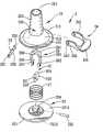
- FIGS. 1 and 2illustrate a conventional supporting device 11 disclosed in U.S. Pat. No. 7,092,521.
- the conventional supporting device 11includes: a hollow base 112 ; a sleeve 111 extending upwardly from the center of the top of the base 112 and having an upper end coupled to a supporting rod 15 that has a clamping end capable of clamping a mobile phone (not shown); a sucking member 12 having a flexible disc body 122 disposed under the base 112 , and a tubular connecting rod 121 connected to a central portion of the disc body 122 and extending upwardly through the base 112 and into the sleeve 111 ; and an operating member 13 disposed outwardly of the sleeve 111 and having an operating plate portion 131 , and two connecting arm portions 132 connected to the operating plate portion 131 .
- Each connecting arm portion 132 of the operating member 13has a pivot end 133 in the form of a cam abutting against a top surface 1121 of the base 112 and connected pivotally to a corresponding one of opposite ends of a pivot rod 14 that extends through two aligned vertical slide slots 113 in the sleeve 111 (only one is shown) and the connecting rod 121 , and that is movable vertically relative to the sleeve 111 .
- a coil spring 16is sleeved on the connecting rod 121 , and is disposed between the base 112 and the disc body 122 for biasing the base 112 to move upwardly.
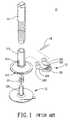
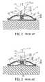
- the supporting device 11can be switched from a non-sucking state, where the base 112 is spaced apart from the sucking member 12 and where the operating plate portion 131 is pivoted away from the base 112 , as shown in FIG. 2 , to a sucking state, where a peripheral portion of the disc body 122 is attached sealingly to a supporting surface 100 as a result of pressing of the base 112 thereon and where a central portion of the disc body 122 is pulled upwardly, thereby forming a vacant space 120 between the supporting surface 100 and the central portion of the disc body 122 , as shown in FIG. 3 , by operating the operating plate portion 131 of the operating member 13 .
- the operating plate portion 131 of the operating member 13is pivoted toward the base 112 such that, initially, the base 112 moves downwardly toward the disc body 122 due to pressing of the pivot end 133 , so as to abut against the peripheral portion of the disc body 122 , and then, an assembly of the pivot rod 14 , the pivot ends 133 of the connecting arm portions 132 of the operating member 13 , the connecting rod 121 and the central portion of the disc body 12 moves upwardly, thereby forming the vacant space 120 .
- the object of the present inventionis to provide a suction device, and a supporting device having the same that can be stably positioned on a supporting surface.
- a suction devicecomprises:
- sucking memberhaving a flexible disc body disposed under the sleeve and having a peripheral portion that is adapted to be attached sealingly to a supporting surface and that abuts against the sleeve, and a central portion connected integrally to the peripheral portion and adapted to be spaced apart from the supporting surface, and a connecting body connected to the central portion of the disc body and extending upwardly into the sleeve;
- a connecting memberdisposed in the sleeve, and having a lower end portion connected to the connecting body of the sucking member so as to allow synchronous movement of the connecting member and the connecting body of the sucking member, an upper end portion, and a cam-accommodating space defined between the lower end portion and the upper end portion;
- cam bodydisposed rotatably in the cam-accommodating space in the connecting member and having an axial hole
- pivot rodextending through the through holes in the annular surrounding wall of the sleeve and pivotable relative to the sleeve about a central axis thereof, the pivot rod having two opposite ends extending outwardly from the sleeve, and a central rod portion extending through and engaging the axial hole in the cam body such that the cam body is pivotable together with the pivot rod;
- an operating memberdisposed outwardly of the sleeve and connected to at least one of the ends of the pivot rod.
- the operating memberis operable so as to pivot an assembly of the pivot rod and the cam body relative to the sleeve such that an assembly of the connecting member and the connecting body of the sucking member is pushed by the cam body to move upwardly away from the supporting surface, thereby forming a vacant space between the central portion of the disc body of the sucking member and the supporting surface.
- a supporting deviceadapted for an electronic device.
- the supporting devicecomprises:
- a suction deviceincluding
- a supporting memberhaving an inserting end portion inserted into an upper end of the sleeve of the suction device, and a mounting end portion adapted to be mounted with the electronic device thereon.
- the operating memberis operable so as to pivot an assembly of the pivot rod and the cam body relative to the sleeve such that an assembly of the connecting member and the connecting body of the sucking member is pushed by the cam body to move upwardly away from the supporting surface, thereby forming a vacant space between the central portion of the disc body of the sucking member and the supporting surface.
- FIG. 1is an exploded perspective view showing a conventional supporting device
- FIG. 2is a schematic partly sectional view showing a suction device of the conventional supporting device when in a non-sucking state
- FIG. 3is a schematic partly sectional view showing the suction device of the conventional suction device when in a sucking state
- FIG. 4is a perspective view showing the first preferred embodiment of a suction device according to the present invention, together with a supporting member to form a supporting device for an electronic device;
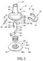
- FIG. 5is an exploded perspective view showing the first preferred embodiment
- FIG. 6is a schematic partly sectional view showing the first preferred embodiment when in a non-sucking state
- FIG. 7is a schematic partly sectional view showing the first preferred embodiment when in a sucking state
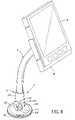
- FIG. 8is a perspective view showing the second preferred embodiment of a suction device according to the present invention, together with a supporting member to form a supporting device for an electronic device;
- FIG. 9is a schematic view showing the second preferred embodiment when in a non-sucking state.
- FIG. 10is a schematic view showing the second preferred embodiment when in a sucking state.
- the first preferred embodiment of a suction device 2is shown to include an upright sleeve 21 , a sucking member 22 , a connecting member 20 , a cam body 25 , a pivot rod 23 , and an operating member 24 .
- the sleeve 21has an open top end 214 , an open bottom end 215 , and a lower end portion 216 having a diameter that increases gradually toward the bottom end 215 (see FIG. 6 ).
- the sleeve 21further has an annular flange 211 that extends radially, horizontally and outwardly from the bottom end 215 , and an annular surrounding wall 213 formed with two aligned through holes 210 .
- the sleeve 21is adapted to permit insertion of an inserting end portion of a supporting member 3 thereinto via the top end 214 .
- the supporting member 3has a mounting end portion 30 for mounting an electronic device 31 thereon, such as a mobile phone, a PDA, or a satellite navigation device, as shown in FIG. 4 .
- the suction device 2is adapted to cooperate with the support member 3 to constitute a repositionable supporting device for the electronic device 31 .
- the sucking member 22has a flexible disk body 221 and a connecting body 220 .
- the disc body 221is disposed under the sleeve 21 , and has a peripheral portion 2211 that is adapted to be attached sealingly to a supporting surface 301 and that is pressed by the annular flange 211 of the sleeve 21 , and a central portion 2212 connected integrally to the peripheral portion 2211 and adapted to be spaced apart from the supporting surface 301 .
- the connecting body 220is connected fixedly to the central portion 2212 of the disc body 221 , and extends upwardly into the sleeve 21 .
- the connecting member 20is disposed in the sleeve 21 , and has a lower end portion connected to the connecting body 220 of the sucking member 22 so as to allow synchronous movement of the connecting member 20 and the connecting body 220 of the sucking member 22 , an upper end portion, and a cam-accommodating space 204 defined between the lower end portion and the upper end portion.
- the connecting member 20is a generally inverted U-shaped plate that has parallel lateral plate portions 202 having lower ends that constitute the lower end portion of the connecting member 20 and that are connected to the connecting body 220 of the sucking member 22 using a connecting bolt 222 , and an intermediate plate portion 201 that constitutes the upper end portion of the connecting member 20 , that interconnects upper ends of the lateral plate portions 202 , and that cooperates with the lateral plate portions 202 to define the cam-accommodating space 204 .
- the intermediate plate portion 201 of the connecting member 20has an inner surface 205 formed with a positioning recess 203 .
- the cam body 25is disposed rotatably in the cam-accommodating space 204 in the connecting member 20 , and has an axial hole 251 .
- the cam body 25is elliptical, and has two projecting edge portions 253 opposite to each other along a major axis thereof.
- the cam bodycan be rhombic, and is chamfered at each corner portion thereof.
- the pivot rod 23extends through the through holes 210 in the annular surrounding wall 213 of the sleeve 21 , and is pivotable relative to the sleeve 21 about a central axis thereof.
- the pivot rod 23has two opposite ends 231 extending outwardly from the sleeve 21 , and a central rod portion 232 extending through and engaging the axial hole 251 in the cam body 25 such that the cam body 25 is pivotable together with the pivot rod 23 .
- the operating member 24is disposed outwardly of the sleeve 21 .
- the operating member 24has an operating plate portion 241 , and two connecting arm portions 242 connected integrally to the operating plate portion 241 .
- Each connecting arm portion 242is formed with an engaging hole 243 that engages a corresponding one of the ends 231 of the pivot rod 23 .
- the operating member 24may have a single connecting arm portion 242 formed with an engaging hole 243 that engages one of the ends 231 of the pivot rod 23 .
- the operating plate portion 241 of the operating member 24is moved downwardly toward the lower end portion 216 so as to pivot an assembly of the pivot rod 23 and the cam body 25 relative to the sleeve 21 such that an assembly of the connecting member 20 and the connecting body 220 of the sucking member 22 is pushed by the cam body 25 to move upwardly away from the supporting surface 301 , thereby forming a vacant space 26 between the central portion 2212 of the disc body 221 of the sucking member 22 and the supporting surface 301 , as best shown in FIG. 7 .
- the suction device 2is in a sucking state.
- the suction device 2further includes a coil spring 27 , which is disposed in the sleeve 21 , is sleeved around the connecting member 20 ., and has opposite ends abutting respectively against the lower end portion 216 of the sleeve 21 and the central portion 2212 of the disk body 221 , for biasing the central portion 2212 of the disk body 221 to move downwardly when the projecting edge portions 253 of the cam body 25 disengages the positioning recess 203 in the inner surface 205 of the intermediate plate portion 201 of the connecting member 20 .
- a coil spring 27which is disposed in the sleeve 21 , is sleeved around the connecting member 20 ., and has opposite ends abutting respectively against the lower end portion 216 of the sleeve 21 and the central portion 2212 of the disk body 221 , for biasing the central portion 2212 of the disk body 221 to move downwardly when the projecting edge portions 253 of the cam body 25 disengages the positioning reces
- the cam body 25since the cam body 25 is disposed in the sleeve 21 , frictional wearing of the top surface 1121 of the base 112 (see FIG. 3 ) as encountered in the prior art can be avoided. Furthermore, due to the presence of the positioning recess 203 in the inner surface 205 of the intermediate plate portion 201 of the connecting member 20 , the cam body 25 can be stably positioned in the sleeve 21 so as to maintain the vacant space 26 when the suction device 2 is in the sucking state, thereby enabling the suction device 2 of the present invention to be positioned stably on the supporting surface 301 .
- FIGS. 8 to 10illustrate the second preferred embodiment of a suction device 2 ′ according to this invention, which is a modification of the first preferred embodiment.
- the operating member 24 ′is a circular plate formed with a cross-shaped rib 241 ′ on a side surface 240 thereof, and a central engaging hole 243 ′ that engages one of the ends 231 of the pivot rod 23 .
- the operating member 24 ′is rotatable to operate the suction device 2 ′ in a selected one of the non-sucking state (see FIG. 9 ) and the sucking state (see FIG. 10 ).
Landscapes
- Engineering & Computer Science (AREA)
- General Engineering & Computer Science (AREA)
- Mechanical Engineering (AREA)
- Hooks, Suction Cups, And Attachment By Adhesive Means (AREA)
Abstract
Description
This application claims priority of Taiwanese Application No. 096203466, filed on Mar. 2, 2007.
1. Field of the Invention
The invention relates to a suction device, more particularly to a suction device that is repositionable, and a supporting device having the same.
2. Description of the Related Art
The supportingdevice 11 can be switched from a non-sucking state, where thebase 112 is spaced apart from the suckingmember 12 and where theoperating plate portion 131 is pivoted away from thebase 112, as shown inFIG. 2 , to a sucking state, where a peripheral portion of thedisc body 122 is attached sealingly to a supportingsurface 100 as a result of pressing of thebase 112 thereon and where a central portion of thedisc body 122 is pulled upwardly, thereby forming avacant space 120 between the supportingsurface 100 and the central portion of thedisc body 122, as shown inFIG. 3 , by operating theoperating plate portion 131 of theoperating member 13. In actual operation of the supportingdevice 11 from the non-sucking state to the sucking state, theoperating plate portion 131 of theoperating member 13 is pivoted toward thebase 112 such that, initially, thebase 112 moves downwardly toward thedisc body 122 due to pressing of thepivot end 133, so as to abut against the peripheral portion of thedisc body 122, and then, an assembly of thepivot rod 14, the pivot ends133 of the connectingarm portions 132 of theoperating member 13, the connectingrod 121 and the central portion of thedisc body 12 moves upwardly, thereby forming thevacant space 120.
In such a configuration, during the pivoting movement of theoperating member 13, the pivot ends133 of the connectingarm portions 132 of theoperating member 13 are always in contact with thetop surface 1121 of thebase 112, thereby resulting in wearing of thetop surface 1121 of thebase 112, as indicated byreference numeral 101 inFIG. 3 , after a long period of use. Due to wearing of thetop surface 1121 of thebase 112, the supportingdevice 11 cannot be accurately and stably positioned in the sucking state.
Therefore, the object of the present invention is to provide a suction device, and a supporting device having the same that can be stably positioned on a supporting surface.
According to one aspect of the present invention, a suction device comprises:
an upright sleeve having an annular surrounding wall formed with two aligned through holes;
a sucking member having a flexible disc body disposed under the sleeve and having a peripheral portion that is adapted to be attached sealingly to a supporting surface and that abuts against the sleeve, and a central portion connected integrally to the peripheral portion and adapted to be spaced apart from the supporting surface, and a connecting body connected to the central portion of the disc body and extending upwardly into the sleeve;
a connecting member disposed in the sleeve, and having a lower end portion connected to the connecting body of the sucking member so as to allow synchronous movement of the connecting member and the connecting body of the sucking member, an upper end portion, and a cam-accommodating space defined between the lower end portion and the upper end portion;
a cam body disposed rotatably in the cam-accommodating space in the connecting member and having an axial hole;
a pivot rod extending through the through holes in the annular surrounding wall of the sleeve and pivotable relative to the sleeve about a central axis thereof, the pivot rod having two opposite ends extending outwardly from the sleeve, and a central rod portion extending through and engaging the axial hole in the cam body such that the cam body is pivotable together with the pivot rod; and
an operating member disposed outwardly of the sleeve and connected to at least one of the ends of the pivot rod.
The operating member is operable so as to pivot an assembly of the pivot rod and the cam body relative to the sleeve such that an assembly of the connecting member and the connecting body of the sucking member is pushed by the cam body to move upwardly away from the supporting surface, thereby forming a vacant space between the central portion of the disc body of the sucking member and the supporting surface.
According to another aspect of the present invention, there is provided a supporting device adapted for an electronic device. The supporting device comprises:
a suction device including
- an upright sleeve having an annular surrounding wall formed with two aligned through holes,
- a sucking member having a flexible disc body disposed under the sleeve and having a peripheral portion that is adapted to be attached sealingly to a supporting surface and that abuts against the sleeve, and a central portion connected integrally to the peripheral portion and adapted to be spaced apart from the supporting surface, and a connecting body connected to the central portion of the disc body and extending upwardly into the sleeve,
- a connecting member disposed in the sleeve, and having a lower end portion connected to the connecting body of the sucking member so as to allow synchronous movement of the connecting member and the connecting body of the sucking member, an upper end portion, and a cam-accommodating space defined between the lower end portion and the upper end portion,
- a cam body disposed rotatably in the cam-accommodating space in the connecting member and having an axial hole,
- a pivot rod extending through the through holes in the annular surrounding wall of the sleeve and pivotable relative to the sleeve about a central axis thereof, the pivot rod having two opposite ends extending outwardly from the sleeve, and a central rod portion extending through and engaging the axial hole in the cam body such that the cam body is pivotable together with the pivot rod, and
- an operating member disposed outwardly of the sleeve and connected to at least one of the ends of the pivot rod; and
a supporting member having an inserting end portion inserted into an upper end of the sleeve of the suction device, and a mounting end portion adapted to be mounted with the electronic device thereon.
The operating member is operable so as to pivot an assembly of the pivot rod and the cam body relative to the sleeve such that an assembly of the connecting member and the connecting body of the sucking member is pushed by the cam body to move upwardly away from the supporting surface, thereby forming a vacant space between the central portion of the disc body of the sucking member and the supporting surface.
Other features and advantages of the present invention will become apparent in the following detailed description of the preferred embodiments with reference to the accompanying drawings, of which:
Before the present invention is described in greater detail, it should be noted that like elements are denoted by the same reference numerals throughout the disclosure.
Referring toFIGS. 4 to 6 , the first preferred embodiment of asuction device 2 according to the present invention is shown to include anupright sleeve 21, a suckingmember 22, a connectingmember 20, acam body 25, apivot rod 23, and anoperating member 24.
Thesleeve 21 has anopen top end 214, anopen bottom end 215, and alower end portion 216 having a diameter that increases gradually toward the bottom end215 (seeFIG. 6 ). Thesleeve 21 further has anannular flange 211 that extends radially, horizontally and outwardly from thebottom end 215, and an annular surroundingwall 213 formed with two aligned throughholes 210. In this embodiment, thesleeve 21 is adapted to permit insertion of an inserting end portion of a supportingmember 3 thereinto via thetop end 214. The supportingmember 3 has amounting end portion 30 for mounting anelectronic device 31 thereon, such as a mobile phone, a PDA, or a satellite navigation device, as shown inFIG. 4 . As such, thesuction device 2 is adapted to cooperate with thesupport member 3 to constitute a repositionable supporting device for theelectronic device 31.
The suckingmember 22 has aflexible disk body 221 and a connectingbody 220. Thedisc body 221 is disposed under thesleeve 21, and has aperipheral portion 2211 that is adapted to be attached sealingly to a supportingsurface 301 and that is pressed by theannular flange 211 of thesleeve 21, and acentral portion 2212 connected integrally to theperipheral portion 2211 and adapted to be spaced apart from the supportingsurface 301. Theconnecting body 220 is connected fixedly to thecentral portion 2212 of thedisc body 221, and extends upwardly into thesleeve 21.
The connectingmember 20 is disposed in thesleeve 21, and has a lower end portion connected to the connectingbody 220 of the suckingmember 22 so as to allow synchronous movement of the connectingmember 20 and the connectingbody 220 of the suckingmember 22, an upper end portion, and a cam-accommodating space 204 defined between the lower end portion and the upper end portion. In this embodiment, the connectingmember 20 is a generally inverted U-shaped plate that has parallellateral plate portions 202 having lower ends that constitute the lower end portion of the connectingmember 20 and that are connected to the connectingbody 220 of the suckingmember 22 using a connectingbolt 222, and anintermediate plate portion 201 that constitutes the upper end portion of the connectingmember 20, that interconnects upper ends of thelateral plate portions 202, and that cooperates with thelateral plate portions 202 to define the cam-accommodatingspace 204. In this embodiment, theintermediate plate portion 201 of the connectingmember 20 has aninner surface 205 formed with apositioning recess 203.
Thecam body 25 is disposed rotatably in the cam-accommodatingspace 204 in the connectingmember 20, and has anaxial hole 251. In this embodiment, thecam body 25 is elliptical, and has two projectingedge portions 253 opposite to each other along a major axis thereof. In an alternative embodiment, the cam body can be rhombic, and is chamfered at each corner portion thereof.
Thepivot rod 23 extends through the throughholes 210 in theannular surrounding wall 213 of thesleeve 21, and is pivotable relative to thesleeve 21 about a central axis thereof. Thepivot rod 23 has twoopposite ends 231 extending outwardly from thesleeve 21, and acentral rod portion 232 extending through and engaging theaxial hole 251 in thecam body 25 such that thecam body 25 is pivotable together with thepivot rod 23. When thecam body 25 rotates in thesleeve 21, one of the projectingedge portions 253 of the cam body abuts movably against theinner surface 205 of theintermediate plate portion 201 of the connectingmember 20 so as to push upwardly the connectingmember 20, as shown inFIG. 7 .
The operatingmember 24 is disposed outwardly of thesleeve 21. In this embodiment, the operatingmember 24 has anoperating plate portion 241, and two connectingarm portions 242 connected integrally to theoperating plate portion 241. Each connectingarm portion 242 is formed with anengaging hole 243 that engages a corresponding one of theends 231 of thepivot rod 23. It is noted that, in an alternative embodiment, the operatingmember 24 may have a single connectingarm portion 242 formed with anengaging hole 243 that engages one of theends 231 of thepivot rod 23.
In actual operation, the operatingplate portion 241 of the operatingmember 24 is moved downwardly toward thelower end portion 216 so as to pivot an assembly of thepivot rod 23 and thecam body 25 relative to thesleeve 21 such that an assembly of the connectingmember 20 and the connectingbody 220 of the suckingmember 22 is pushed by thecam body 25 to move upwardly away from the supportingsurface 301, thereby forming avacant space 26 between thecentral portion 2212 of thedisc body 221 of the suckingmember 22 and the supportingsurface 301, as best shown inFIG. 7 . Hence, thesuction device 2 is in a sucking state. It is noted that, when thesuction device 2 is in the sucking state, one of the projectingedge portions 253 of thecam body 25 engages thepositioning recess 203 in theinner surface 205 of theintermediate plate portion 201 of the connectingmember 20 so as to stably position thecam body 25 in the sleeve21 (seeFIG. 7 ), thereby maintaining thevacant space 26 between thecentral portion 2212 of thedisc body 221 of the suckingmember 22 and the supportingsurface 301. On the other hand, when thesuction device 2 is in a non-sucking state, as shown inFIG. 6 , in this embodiment, a part of anannular surrounding surface 252 of thecam body 25 abuts against theinner surface 205 of theintermediate plate portion 201 of the connectingmember 20. However, such abutment is not necessary in other embodiments.
Furthermore, thesuction device 2 further includes acoil spring 27, which is disposed in thesleeve 21, is sleeved around the connecting member20., and has opposite ends abutting respectively against thelower end portion 216 of thesleeve 21 and thecentral portion 2212 of thedisk body 221, for biasing thecentral portion 2212 of thedisk body 221 to move downwardly when the projectingedge portions 253 of thecam body 25 disengages thepositioning recess 203 in theinner surface 205 of theintermediate plate portion 201 of the connectingmember 20.
In this invention, since thecam body 25 is disposed in thesleeve 21, frictional wearing of thetop surface 1121 of the base112 (seeFIG. 3 ) as encountered in the prior art can be avoided. Furthermore, due to the presence of thepositioning recess 203 in theinner surface 205 of theintermediate plate portion 201 of the connectingmember 20, thecam body 25 can be stably positioned in thesleeve 21 so as to maintain thevacant space 26 when thesuction device 2 is in the sucking state, thereby enabling thesuction device 2 of the present invention to be positioned stably on the supportingsurface 301.
While the present invention has been described in connection with what are considered the most practical and preferred embodiments, it is understood that this invention is not limited to the disclosed embodiments but is intended to cover various arrangements included within the spirit and scope of the broadest interpretation so as to encompass all such modifications and equivalent arrangements.
Claims (12)
1. A suction device comprising:
an upright sleeve having an annular surrounding wall formed with two aligned through holes;
a sucking member having a flexible disc body disposed under said sleeve and having a peripheral portion that is adapted to be attached sealingly to a supporting surface and that abuts against said sleeve, and a central portion connected integrally to said peripheral portion and adapted to be spaced apart from the supporting surface, and a connecting body connected to said central portion of said disc body and extending upwardly into said sleeve;
a connecting member disposed in said sleeve, and having a lower end portion connected to said connecting body of said sucking member so as to allow synchronous movement of said connecting member and said connecting body of said sucking member, an upper end portion, and a cam-accommodating space defined between said lower end portion and said upper end portion;
a cam body disposed rotatably in said cam-accommodating space in said connecting member and having an axial hole;
a pivot rod extending through said through holes in said annular surrounding wall of said sleeve and pivotable relative to said sleeve about a central axis thereof, said pivot rod having two opposite ends extending outwardly from said sleeve, and a central rod portion extending through and engaging said axial hole in said cam body such that said cam body is pivotable together with said pivot rod; and
an operating member disposed outwardly of said sleeve and connected to at least one of said ends of said pivot rod;
wherein said operating member is operable so as to pivot an assembly of said pivot rod and said cam body relative to said sleeve such that an assembly of said connecting member and said connecting body of said sucking member is pushed by said cam body to move upwardly away from the supporting surface, thereby forming a vacant space between said central portion of said disc body of said sucking member and the supporting surface; and
wherein said connecting member is a generally inverted U-shaped plate that has opposite lateral plate portions connected respectively to opposite sides of said connecting body of said sucking member, and an intermediate plate portion interconnecting said lateral plate portions, cooperating with said lateral plate portions to define said cam-accommodating space, and abutting against said cam body when said vacant space is formed.
2. The suction device as claimed inclaim 1 , wherein:
said intermediate plate portion of said connecting member has an inner surface; and
said cam body is elliptical and has two projecting edge portions opposite to each other along a major axis thereof such that, when said cam body rotates in said sleeve, one of said projecting edge portions of said cam body abuts movably against said inner surface of said intermediate plate portion of said connecting member so as to push upwardly said connecting member.
3. The suction device as claimed inclaim 2 , wherein said inner surface of said intermediate plate portion of said connecting member is formed with a positioning recess that engages said one of said projecting edge portions of said cam body so as to position said cam body in said sleeve when said vacant space is formed, thereby maintaining said vacant space between said central portion of said disc body of said sucking member and the supporting surface.
4. The suction device as claimed inclaim 3 , wherein said sleeve further has a lower end portion, said suction device further comprising a coil spring disposed in said sleeve and sleeved around said connecting member, said coil spring having opposite ends abutting respectively against said lower end portion of said sleeve and said central portion of said disk body for biasing said central portion of said disk body to move downwardly when said projecting edge portions of said cam body disengages said positioning recess in said inner surface of said intermediate plate portion of said connecting member.
5. The suction device as claimed inclaim 1 , wherein said operating member has an operating plate portion, and a connecting arm portion connected to said operating plate portion and formed with an engaging hole that engages said pivot rod.
6. The suction device as claimed inclaim 1 , wherein said sleeve further has an annular flange extending radially, horizontally and outwardly from a bottom end thereof and pressing downwardly against said peripheral portion of said disc body of said sucking member.
7. A supporting device adapted for an electronic device, comprising:
a suction device including
an upright sleeve having an annular surrounding wall formed with two aligned through holes,
a sucking member having a flexible disc body disposed under said sleeve and having a peripheral portion that is adapted to be attached sealingly to a supporting surface and that abuts against said sleeve, and a central portion connected integrally to said peripheral portion and adapted to be spaced apart from the supporting surface, and a connecting body connected to said central portion of said disc body and extending upwardly into said sleeve,
a connecting member disposed in said sleeve, and having a lower end portion connected to said connecting body of said sucking member so as to allow synchronous movement of said connecting member and said connecting body of said sucking member, an upper end portion, and a cam-accommodating space defined between said lower end portion and said upper end portion,
a cam body disposed rotatably in said cam-accommodating space in said connecting member and having an axial hole,
a pivot rod extending through said through holes in said annular surrounding wall of said sleeve and pivotable relative to said sleeve about a central axis thereof, said pivot rod having two opposite ends extending outwardly from said sleeve, and a central rod portion extending through and engaging said axial hole in said cam body such that said cam body is pivotable together with said pivot rod, and
an operating member disposed outwardly of said sleeve and connected to at least one of said ends of said pivot rod; and
a supporting member having an inserting end portion inserted into an upper end of said sleeve of said suction device, and a mounting end portion adapted to be mounted with the electronic device thereon;
wherein said operating member is operable so as to pivot an assembly of said pivot rod and said cam body relative to said sleeve such that an assembly of said connecting member and said connecting body of said sucking member is pushed by said cam body to move upwardly away from the supporting surface, thereby forming a vacant space between said central portion of said disc body of said sucking member and the supporting surface; and
wherein said connecting member of said suction device is a generally inverted U-shaped plate that has opposite lateral plate portions connected respectively to opposite sides of said connecting body of said sucking member, and an intermediate plate portion interconnecting said lateral plate portions, cooperating with said lateral plate portions to define said cam-accommodating space, and abutting against said cam body when said vacant space is formed.
8. The supporting device as claimed inclaim 7 , wherein:
said intermediate plate portion of said connecting member of said suction device has an inner surface; and
said cam body of said suction device is elliptical and has two projecting edge portions opposite to each other along a major axis thereof such that, when said cam body rotates in said sleeve, one of said projecting edge portions of said cam body abuts movably against said inner surface of said intermediate plate portion of said connecting member so as to push upwardly said connecting member.
9. The supporting device as claimed inclaim 8 , wherein said inner surface of said intermediate plate portion of said connecting member of said suction device is formed with a positioning recess that engages said one of said projecting edge portions of said cam body so as to position said cam body in said sleeve when said vacant space is formed, thereby maintaining said vacant space between said central portion of said disc body of said sucking member and the supporting surface.
10. The supporting device as claimed inclaim 9 , wherein said sleeve of said suction device further has a lower end portion; and said suction device further includes a coil spring disposed in said sleeve and sleeved around said connecting member, said coil spring having opposite ends abutting respectively against said lower end portion of said sleeve and said central portion of said disk body for biasing said central portion of said disk body to move downwardly when said projecting edge portions of said cam body disengages said positioning recess in said inner surface of said intermediate plate portion of said connecting member.
11. The supporting device as claimed inclaim 7 , wherein said operating member of said suction device has an operating plate portion, and a connecting arm portion connected to said operating plate portion and formed with an engaging hole that engages said pivot rod.
12. The supporting device as claimed inclaim 7 , wherein said sleeve of said suction device further has an annular flange extending radially, horizontally and outwardly from a bottom end thereof and pressing downwardly against said peripheral portion of said disc body of said sucking member.
Applications Claiming Priority (3)
| Application Number | Priority Date | Filing Date | Title |
|---|---|---|---|
| TW96203466U | 2007-03-02 | ||
| TW096203466 | 2007-03-02 | ||
| TW096203466UTWM322483U (en) | 2007-03-02 | 2007-03-02 | Suction device and detachable electronic device rack having the suction device |
Publications (2)
| Publication Number | Publication Date |
|---|---|
| US20080210833A1 US20080210833A1 (en) | 2008-09-04 |
| US7658354B2true US7658354B2 (en) | 2010-02-09 |
Family
ID=39309569
Family Applications (1)
| Application Number | Title | Priority Date | Filing Date |
|---|---|---|---|
| US11/896,322Expired - Fee RelatedUS7658354B2 (en) | 2007-03-02 | 2007-08-31 | Suction device and supporting device having the same |
Country Status (2)
| Country | Link |
|---|---|
| US (1) | US7658354B2 (en) |
| TW (1) | TWM322483U (en) |
Cited By (21)
| Publication number | Priority date | Publication date | Assignee | Title |
|---|---|---|---|---|
| US20080105800A1 (en)* | 2006-11-03 | 2008-05-08 | John Menning | Cleat-mountable accessory apparatus |
| US20090193661A1 (en)* | 2008-02-01 | 2009-08-06 | Kwok Kuen So | Kitchen Utensil with a Suction Base Mechanism |
| US20120067911A1 (en)* | 2010-09-20 | 2012-03-22 | Michael Norment | Detachable basket with vacuum attachments |
| US20130099075A1 (en)* | 2011-10-21 | 2013-04-25 | Hon Hai Precision Industry Co., Ltd. | Support device |
| US20130269793A1 (en)* | 2012-04-13 | 2013-10-17 | Pi Kuang Tsai | Holder device for shower nozzle or the like |
| US8919712B2 (en)* | 2010-06-29 | 2014-12-30 | Ferro-Carbon Ent. Co., Ltd. | Sucker assembly having a better attachment effect |
| US9307838B1 (en)* | 2014-02-17 | 2016-04-12 | Michael A. Blavat | Fishing rod holder |
| USD755585S1 (en) | 2014-07-30 | 2016-05-10 | National Presto Industries, Inc. | Kitchen utensil |
| USD755583S1 (en) | 2014-07-30 | 2016-05-10 | National Presto Industries, Inc. | Kitchen utensil |
| US9635983B2 (en) | 2014-07-30 | 2017-05-02 | National Presto Industries, Inc. | Countertop device having retention feature |
| US9987489B2 (en) | 2015-03-27 | 2018-06-05 | Elwha Llc | Controlling ear stimulation in response to electrical contact sensing |
| US10039928B2 (en) | 2015-03-27 | 2018-08-07 | Equility Llc | Ear stimulation with neural feedback sensing |
| US10327984B2 (en) | 2015-03-27 | 2019-06-25 | Equility Llc | Controlling ear stimulation in response to image analysis |
| US10398902B2 (en) | 2015-03-27 | 2019-09-03 | Equility Llc | Neural stimulation method and system with audio output |
| US10406376B2 (en) | 2015-03-27 | 2019-09-10 | Equility Llc | Multi-factor control of ear stimulation |
| US10512783B2 (en) | 2015-03-27 | 2019-12-24 | Equility Llc | User interface method and system for ear stimulation |
| US10589105B2 (en) | 2015-03-27 | 2020-03-17 | The Invention Science Fund Ii, Llc | Method and system for controlling ear stimulation |
| US10610062B2 (en)* | 2018-08-31 | 2020-04-07 | Jeffery Alan Mieldon | Washcloth identification system |
| US20200291689A1 (en)* | 2019-03-12 | 2020-09-17 | Wistron Corporation | Lock mechanism and holding structure for electronic device |
| US11364380B2 (en) | 2015-03-27 | 2022-06-21 | Elwha Llc | Nerve stimulation system, subsystem, headset, and earpiece |
| US11892027B1 (en)* | 2022-09-30 | 2024-02-06 | Ruochen Fan | Suction cup type hook |
Families Citing this family (8)
| Publication number | Priority date | Publication date | Assignee | Title |
|---|---|---|---|---|
| TWM318683U (en)* | 2006-12-22 | 2007-09-11 | Lite On Technology Corp | Suction plate and removable electronic device fastener with the same |
| GB2470898B (en)* | 2009-06-08 | 2013-01-23 | Bb Ipr Ltd | A suction fixing |
| TWI600840B (en)* | 2016-08-05 | 2017-10-01 | Press suction cup structure | |
| CN107009298B (en)* | 2017-04-26 | 2018-09-25 | 深圳市明信测试设备有限公司 | A kind of vacuum slot quick change construction |
| CN107606446A (en)* | 2017-10-19 | 2018-01-19 | 苏州傲儒塑胶有限公司 | One kind is connected device and its method of work |
| CA3089618A1 (en)* | 2018-01-26 | 2019-08-01 | Bing Innovations, L.L.C. | Reducing pain at a medical treatment site |
| CN114089851B (en)* | 2020-07-30 | 2024-03-01 | 明基智能科技(上海)有限公司 | Wire clamping device |
| USD989986S1 (en)* | 2021-09-16 | 2023-06-20 | Hugo E Morales | Pool ladder socket cover |
Citations (9)
| Publication number | Priority date | Publication date | Assignee | Title |
|---|---|---|---|---|
| US6234435B1 (en)* | 1999-10-13 | 2001-05-22 | Ta Kuang Yeh | Sucking disk support |
| US6308923B1 (en)* | 1999-12-10 | 2001-10-30 | Herman S. Howard | Suction support assembly |
| US6550735B1 (en)* | 2002-01-25 | 2003-04-22 | Zhi-Yuan Zheng | Sucker-type suspension structure |
| US6749160B1 (en)* | 2003-03-12 | 2004-06-15 | Herbert Richter | Suction disc mounting arrangement |
| US7007908B2 (en)* | 2004-06-23 | 2006-03-07 | Wen-Feng Tsay | Sucking disk type hanging pole |
| US7066434B2 (en)* | 2002-08-01 | 2006-06-27 | Golden Peak Plastic Works Limited | Suction-adhesive device |
| US7092521B2 (en) | 2004-01-20 | 2006-08-15 | Chin Yang Wang | Fixed base assembly of mobile phone |
| US7293750B2 (en)* | 2005-10-05 | 2007-11-13 | Harald Richter | Suction base for an apparatus support device |
| US20070262217A1 (en)* | 2006-05-15 | 2007-11-15 | Leland Wang | Sucking disc apparatus |
- 2007
- 2007-03-02TWTW096203466Upatent/TWM322483U/ennot_activeIP Right Cessation
- 2007-08-31USUS11/896,322patent/US7658354B2/ennot_activeExpired - Fee Related
Patent Citations (9)
| Publication number | Priority date | Publication date | Assignee | Title |
|---|---|---|---|---|
| US6234435B1 (en)* | 1999-10-13 | 2001-05-22 | Ta Kuang Yeh | Sucking disk support |
| US6308923B1 (en)* | 1999-12-10 | 2001-10-30 | Herman S. Howard | Suction support assembly |
| US6550735B1 (en)* | 2002-01-25 | 2003-04-22 | Zhi-Yuan Zheng | Sucker-type suspension structure |
| US7066434B2 (en)* | 2002-08-01 | 2006-06-27 | Golden Peak Plastic Works Limited | Suction-adhesive device |
| US6749160B1 (en)* | 2003-03-12 | 2004-06-15 | Herbert Richter | Suction disc mounting arrangement |
| US7092521B2 (en) | 2004-01-20 | 2006-08-15 | Chin Yang Wang | Fixed base assembly of mobile phone |
| US7007908B2 (en)* | 2004-06-23 | 2006-03-07 | Wen-Feng Tsay | Sucking disk type hanging pole |
| US7293750B2 (en)* | 2005-10-05 | 2007-11-13 | Harald Richter | Suction base for an apparatus support device |
| US20070262217A1 (en)* | 2006-05-15 | 2007-11-15 | Leland Wang | Sucking disc apparatus |
Cited By (26)
| Publication number | Priority date | Publication date | Assignee | Title |
|---|---|---|---|---|
| US20080105800A1 (en)* | 2006-11-03 | 2008-05-08 | John Menning | Cleat-mountable accessory apparatus |
| US8851434B2 (en)* | 2006-11-03 | 2014-10-07 | Lc Watersports, Inc. | Cleat-mountable accessory apparatus |
| US20090193661A1 (en)* | 2008-02-01 | 2009-08-06 | Kwok Kuen So | Kitchen Utensil with a Suction Base Mechanism |
| US7861647B2 (en)* | 2008-02-01 | 2011-01-04 | Kwok Kuen So | Kitchen utensil with a suction base mechanism |
| US8919712B2 (en)* | 2010-06-29 | 2014-12-30 | Ferro-Carbon Ent. Co., Ltd. | Sucker assembly having a better attachment effect |
| US20120067911A1 (en)* | 2010-09-20 | 2012-03-22 | Michael Norment | Detachable basket with vacuum attachments |
| US20130099075A1 (en)* | 2011-10-21 | 2013-04-25 | Hon Hai Precision Industry Co., Ltd. | Support device |
| US20130269793A1 (en)* | 2012-04-13 | 2013-10-17 | Pi Kuang Tsai | Holder device for shower nozzle or the like |
| US9307838B1 (en)* | 2014-02-17 | 2016-04-12 | Michael A. Blavat | Fishing rod holder |
| US9936838B2 (en) | 2014-07-30 | 2018-04-10 | National Presto Industries, Inc. | Countertop device having retention feature |
| USD755583S1 (en) | 2014-07-30 | 2016-05-10 | National Presto Industries, Inc. | Kitchen utensil |
| US9635983B2 (en) | 2014-07-30 | 2017-05-02 | National Presto Industries, Inc. | Countertop device having retention feature |
| USD755585S1 (en) | 2014-07-30 | 2016-05-10 | National Presto Industries, Inc. | Kitchen utensil |
| US10406376B2 (en) | 2015-03-27 | 2019-09-10 | Equility Llc | Multi-factor control of ear stimulation |
| US10039928B2 (en) | 2015-03-27 | 2018-08-07 | Equility Llc | Ear stimulation with neural feedback sensing |
| US10293158B2 (en) | 2015-03-27 | 2019-05-21 | Equility Llc | Controlling ear stimulation in response to a status of a subject |
| US10327984B2 (en) | 2015-03-27 | 2019-06-25 | Equility Llc | Controlling ear stimulation in response to image analysis |
| US10398902B2 (en) | 2015-03-27 | 2019-09-03 | Equility Llc | Neural stimulation method and system with audio output |
| US9987489B2 (en) | 2015-03-27 | 2018-06-05 | Elwha Llc | Controlling ear stimulation in response to electrical contact sensing |
| US10512783B2 (en) | 2015-03-27 | 2019-12-24 | Equility Llc | User interface method and system for ear stimulation |
| US10589105B2 (en) | 2015-03-27 | 2020-03-17 | The Invention Science Fund Ii, Llc | Method and system for controlling ear stimulation |
| US11364380B2 (en) | 2015-03-27 | 2022-06-21 | Elwha Llc | Nerve stimulation system, subsystem, headset, and earpiece |
| US10610062B2 (en)* | 2018-08-31 | 2020-04-07 | Jeffery Alan Mieldon | Washcloth identification system |
| US20200291689A1 (en)* | 2019-03-12 | 2020-09-17 | Wistron Corporation | Lock mechanism and holding structure for electronic device |
| US11879272B2 (en)* | 2019-03-12 | 2024-01-23 | Wistron Corporation | Lock mechanism and holding structure for electronic device |
| US11892027B1 (en)* | 2022-09-30 | 2024-02-06 | Ruochen Fan | Suction cup type hook |
Also Published As
| Publication number | Publication date |
|---|---|
| TWM322483U (en) | 2007-11-21 |
| US20080210833A1 (en) | 2008-09-04 |
Similar Documents
| Publication | Publication Date | Title |
|---|---|---|
| US7658354B2 (en) | Suction device and supporting device having the same | |
| US7815155B2 (en) | Suction device and supporting device having the same | |
| US7731139B2 (en) | Suction device and supporting device having the same | |
| US7628364B2 (en) | Fixation device | |
| US7226026B2 (en) | Suction device | |
| US7661648B2 (en) | Sucker device for a fixing support | |
| US20090127411A1 (en) | Structure and mechanism of windshield mount and pedestal for portable electronics device | |
| EP2249074B1 (en) | Holder | |
| US7793899B2 (en) | Structure for a suction device | |
| US7007908B2 (en) | Sucking disk type hanging pole | |
| US9416814B2 (en) | Cradle for a portable device | |
| US20070262217A1 (en) | Sucking disc apparatus | |
| US9534628B1 (en) | Folding device for baby carriage | |
| US7762504B2 (en) | Base for display device | |
| TW201336546A (en) | Support structure for treadmill | |
| US20070120026A1 (en) | Fixture for a communication device | |
| JP2007537378A5 (en) | ||
| US8079166B2 (en) | Support assembly and digital photo frame using the same | |
| GB2438626A (en) | Suction disc apparatus | |
| KR200432614Y1 (en) | Hanger Holder | |
| US20110182063A1 (en) | Table Lamp | |
| KR100625699B1 (en) | Cell Phone Case Rotating Cradle | |
| FR2902474A3 (en) | Suction disc forming device for fixing e.g. cellular phone, on smooth surface, has rod including rectangular slot hole, and control element pivoted with projecting part of body via pivot shaft that passes through hole | |
| JP3123596U (en) | Suction cup structure | |
| KR200377613Y1 (en) | cellular phone case adhesion holder for automobile |
Legal Events
| Date | Code | Title | Description |
|---|---|---|---|
| AS | Assignment | Owner name:LITE-ON TECHNOLOGY CORP., TAIWAN Free format text:ASSIGNMENT OF ASSIGNORS INTEREST;ASSIGNOR:WANG, CHEN-HSING;REEL/FRAME:019812/0964 Effective date:20070820 Owner name:LITE-ON TECHNOLOGY CORP.,TAIWAN Free format text:ASSIGNMENT OF ASSIGNORS INTEREST;ASSIGNOR:WANG, CHEN-HSING;REEL/FRAME:019812/0964 Effective date:20070820 | |
| FEPP | Fee payment procedure | Free format text:PAYOR NUMBER ASSIGNED (ORIGINAL EVENT CODE: ASPN); ENTITY STATUS OF PATENT OWNER: LARGE ENTITY | |
| AS | Assignment | Owner name:DUAL MEMRISTOR LTD. CO. LLC, DELAWARE Free format text:ASSIGNMENT OF ASSIGNORS INTEREST;ASSIGNOR:LITE-ON TECHNOLOGY CORPORATION;REEL/FRAME:027775/0583 Effective date:20111206 | |
| REMI | Maintenance fee reminder mailed | ||
| LAPS | Lapse for failure to pay maintenance fees | ||
| STCH | Information on status: patent discontinuation | Free format text:PATENT EXPIRED DUE TO NONPAYMENT OF MAINTENANCE FEES UNDER 37 CFR 1.362 | |
| FP | Lapsed due to failure to pay maintenance fee | Effective date:20140209 |