US7658241B2 - Underreaming and stabilizing tool and method for its use - Google Patents
Underreaming and stabilizing tool and method for its useDownload PDFInfo
- Publication number
- US7658241B2 US7658241B2US11/109,350US10935005AUS7658241B2US 7658241 B2US7658241 B2US 7658241B2US 10935005 AUS10935005 AUS 10935005AUS 7658241 B2US7658241 B2US 7658241B2
- Authority
- US
- United States
- Prior art keywords
- drive pipe
- longitudinal
- tubular body
- axial cavity
- wedge element
- Prior art date
- Legal status (The legal status is an assumption and is not a legal conclusion. Google has not performed a legal analysis and makes no representation as to the accuracy of the status listed.)
- Expired - Fee Related, expires
Links
- 238000000034methodMethods0.000titleclaimsdescription20
- 230000000087stabilizing effectEffects0.000titledescription29
- 238000005553drillingMethods0.000claimsabstractdescription59
- 230000033001locomotionEffects0.000claimsdescription37
- 230000002093peripheral effectEffects0.000claimsdescription24
- 230000003100immobilizing effectEffects0.000claimsdescription22
- 239000012530fluidSubstances0.000claimsdescription17
- 238000006073displacement reactionMethods0.000claimsdescription13
- 230000008878couplingEffects0.000claimsdescription11
- 238000010168coupling processMethods0.000claimsdescription11
- 238000005859coupling reactionMethods0.000claimsdescription11
- 238000005304joiningMethods0.000claimsdescription10
- 230000015572biosynthetic processEffects0.000description17
- 238000005755formation reactionMethods0.000description17
- 230000004913activationEffects0.000description12
- 230000007246mechanismEffects0.000description11
- 230000008901benefitEffects0.000description8
- 238000005520cutting processMethods0.000description6
- 238000011144upstream manufacturingMethods0.000description5
- 238000004891communicationMethods0.000description4
- 238000009434installationMethods0.000description4
- 230000008859changeEffects0.000description3
- 238000000465mouldingMethods0.000description3
- 238000006467substitution reactionMethods0.000description3
- 230000004075alterationEffects0.000description2
- 230000009849deactivationEffects0.000description2
- 230000007423decreaseEffects0.000description2
- 238000012423maintenanceMethods0.000description2
- 238000012986modificationMethods0.000description2
- 230000004048modificationEffects0.000description2
- 230000002829reductive effectEffects0.000description2
- 238000009419refurbishmentMethods0.000description2
- 230000009471actionEffects0.000description1
- 239000012190activatorSubstances0.000description1
- 238000005266castingMethods0.000description1
- 238000006243chemical reactionMethods0.000description1
- 230000003247decreasing effectEffects0.000description1
- 229910003460diamondInorganic materials0.000description1
- 239000010432diamondSubstances0.000description1
- 230000006870functionEffects0.000description1
- 238000002347injectionMethods0.000description1
- 239000007924injectionSubstances0.000description1
- 238000003780insertionMethods0.000description1
- 230000037431insertionEffects0.000description1
- 230000000670limiting effectEffects0.000description1
- 230000010349pulsationEffects0.000description1
- 230000004044responseEffects0.000description1
- 230000000284resting effectEffects0.000description1
- 238000010008shearingMethods0.000description1
- 238000003860storageMethods0.000description1
- 239000002699waste materialSubstances0.000description1
- 238000003466weldingMethods0.000description1
Images


Classifications
- E—FIXED CONSTRUCTIONS
- E21—EARTH OR ROCK DRILLING; MINING
- E21B—EARTH OR ROCK DRILLING; OBTAINING OIL, GAS, WATER, SOLUBLE OR MELTABLE MATERIALS OR A SLURRY OF MINERALS FROM WELLS
- E21B10/00—Drill bits
- E21B10/26—Drill bits with leading portion, i.e. drill bits with a pilot cutter; Drill bits for enlarging the borehole, e.g. reamers
- E21B10/32—Drill bits with leading portion, i.e. drill bits with a pilot cutter; Drill bits for enlarging the borehole, e.g. reamers with expansible cutting tools
- E21B10/322—Drill bits with leading portion, i.e. drill bits with a pilot cutter; Drill bits for enlarging the borehole, e.g. reamers with expansible cutting tools cutter shifted by fluid pressure
Definitions
- This inventionrelates in general to earth formation drilling tools and methods, and more particularly to an underreaming and stabilizing tool to be put into service in a drilling hole and a method for its use.
- Earth formation drillingis often accomplished using a long string of drilling pipes and tools coupled together.
- the drilling stringis rotated together in order to rotate a cutting bit at the end of the string.
- This cutting bitcreates the hole which the rest of the drilling string moves through.
- Bore-hole underreamersexist to accomplish the widening of the hole.
- An underreamermay be coupled to the drilling string between two other elements of the drilling string. It may then be sent down hole with the drilling string, rotating with the drilling string, and widening the hole.
- underreamer designsexist. Some have fixed cutting blades around the periphery of the underreamer and some have expandable blades or arms. Various types and hardness of earth formations also exist. Aggressive blades, extending quickly and/or relatively far beyond the periphery of the underreamer body, may be used in soft formations; and less aggressive blades, extending more slowly and/or a shorter distance beyond the periphery of the underreamer body, may be used in harder formations. Different types of formations may exist down the length of a drilling hole, and it may be desirable to widen the hole through each of these formation types. If the blades or arms with which the underreamer is equipped are not suitable for the types of formations being widened, the underreamer may need to be replaced.
- the blades or arms of the underreamermay become worn.
- the underreamerWhen the underreamer is no longer able to perform a widening of the drilling hole, it may be withdrawn from the drilling hole and disconnected from the drilling string.
- a new underreamermay be put in its place, and the worn underreamer may be sent for retooling and refurbishment. Sending the worn underreamer away for retooling and refurbishment may result in costly down time or increased inventory and maintenance costs by requiring a replacement underreamer to be kept available.
- a drilling toolthat includes a tubular body defining a longitudinal axial cavity extending therethrough.
- the tubular bodyalso defines at least one radial guidance channel extending radially from the axial cavity through the tubular body.
- a cutter elementis disposed in the at least one radial guidance channel and includes an internal surface inclined at an angle to a longitudinal axis of the tubular body.
- the drilling toolalso includes a wedge element having an external surface configured to engage the internal surface of the cutter element and to direct the cutter element from a retracted position to an extended position as the wedge element moves from a first position to a second position.
- Certain embodiments of the present inventionmay also include a drive pipe disposed within the axial cavity and coupled to the wedge element.
- the drive pipemay be configured to move the wedge element from the first position to the second position as the drive pipe moves from a first longitudinal position to a second longitudinal position.
- Certain embodimentsmay also include the drive pipe defining a longitudinal slot along an intermediate portion of the drive pipe.
- the drive pipemay also define a peripheral slot disposed adjacent a first end of the longitudinal slot.
- the drive pipemay be configured to permit the wedge element to slide within the longitudinal slot when the drive pipe is in a first angular position and to fixedly couple the wedge element to the peripheral slot of the drive pipe as the drive pipe is rotated from the first angular position to a second angular position.
- the drive pipemay define at least a first longitudinal groove having a length corresponding to a distance between the first and second longitudinal positions of the drive pipe.
- the tubular bodymay further define at least a first aperture aligning with the first longitudinal groove when the drive pipe is in the second angular position.
- a generally cylindrical immobilizing elementmay pass through the first aperture and protrude into the first longitudinal groove.
- a methodmay include installing a cutter element and a wedge element at least partially within a radial guidance channel of a tubular body by passing the cutter element through a longitudinal axial cavity of the tubular body.
- the cutter element and the wedge elementmay then be moved radially outward from the longitudinal axial cavity at least partially into the radial guidance channel.
- the cutter elementmay be moved from a retracted position to an extended position by moving the wedge element from a first longitudinal position to a second longitudinal position.
- Certain embodimentsmay include coupling the wedge element to the cutter element before installing the cutter element and the wedge element at least partially within the radial guidance channel.
- Another particular embodimentmay include installing the drive pipe in the axial cavity by: orienting the drive pipe in a first angular position, inserting an end of the drive pipe into an end of the tubular body, sliding the drive pipe into the axial cavity, and rotating the drive pipe to a second angular position.
- a particular alternative embodiment of the present inventionmay include increasing a fluid pressure of a drilling fluid circulating inside an axial cavity of a tubular body.
- a surface pressure on a piston of a drive pipe disposed within the axial cavity of the tubular bodyis increased by increasing the fluid pressure of the drilling fluid.
- a longitudinal movement of the drive pipe and a wedge element coupled to the drive pipeis achieved by increasing the surface pressure on the piston.
- a radial movement of a cutter element disposed in a radial guidance channel of the tubular bodyis achieved by directing the longitudinal movement of the drive pipe and the wedge element.
- inventions of certain embodiments of the present inventioninclude an underreamer with cutter elements which are easily replaced, yet held securely within the underreamer.
- the cutter elementsare installed from the inside of the body of the underreamer into radial guidance channels which prevent the cutter elements from extending past a designed extension point. In this manner, the cutter elements of the underreamer may be easily changed to less worn cutter elements or to cutter elements which are more appropriate for a particular formation type. This feature may reduce or eliminate the need to keep multiple underreamers available.
- Additional technical advantages of the present inventioninclude radially movable cutter elements which move in response to fluid pressure changes.
- the fluid pressure acting on the cutter elementsmay be increased to extend the cutter elements and decreased to cause a retraction of the cutter elements.
- the activation devicekeeps the cutter elements in a retracted position until underreaming is desired, and the deactivation device keeps the cutter elements in the retracted position after underreaming is complete. In this manner, the underreamer is not activated when underreaming is not desired. This also avoids unnecessary wear on the underreamer.
- FIG. 1is a perspective view, with portions broken away, illustrating an underreaming and stabilizing tool having cutter elements in a retracted position, in accordance with the teachings of the present invention
- FIG. 2is a perspective view, with portions broken away, illustrating the underreaming and stabilizing tool of FIG. 1 , having cutter elements in a deployed position;
- FIG. 3is a perspective view illustrating a drive pipe of the underreaming and stabilizing tool of FIG. 1 , equipped with wedge elements and cutter elements;
- FIG. 4is a perspective view illustrating the drive pipe of FIG. 3 without the wedge elements and the cutter elements;
- FIG. 5is a longitudinal cross section view of the underreaming and stabilizing tool of FIG. 1 , illustrating the installation of a cutter element and wedge element assembly into the body of the tool;
- FIG. 6is a perspective view, with portions broken away, of the underreaming and stabilizing tool of FIG. 1 , illustrating the installation of the drive pipe into the body of the tool;
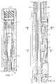
- FIG. 7is a longitudinal cross section view of the top, or upstream, portion of the underreaming and stabilizing tool of FIG. 1 , illustrating the upstream joining element for coupling the upstream portion of the tool with the drill string;
- FIG. 8is a longitudinal cross section view of the middle portion of the underreaming and stabilizing tool of FIG. 1 , illustrating the wedge elements, cutter elements, and a portion of the drive pipe;
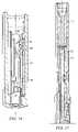
- FIG. 9is a longitudinal cross section view of the middle portion of the underreaming and stabilizing tool of FIG. 1 , illustrating the downstream joining element for coupling the downstream portion of the tool with the drill string;
- FIG. 10is a radial cross section view of the underreaming and stabilizing tool of FIG. 1 through the 10 - 10 line of FIG. 8 ;
- FIG. 11is a radial cross section view of the underreaming and stabilizing tool of FIG. 1 through the 11 - 11 line of FIG. 8 ;
- FIG. 12is a perspective view, with portions broken away, of the underreaming and stabilizing tool of FIG. 1 , illustrating an activation device in a deactivated position corresponding to the withdrawn position of the cutter elements;
- FIG. 13is a perspective view, with portions broken away, of the underreaming and stabilizing tool of FIG. 1 , illustrating the activation device of FIG. 12 in an activated position corresponding to the extended position of the cutter elements;
- FIG. 14is a perspective view, with portions broken away, of the underreaming and stabilizing tool of FIG. 1 , illustrating the activation device of FIG. 12 in an activated position corresponding to the withdrawn position of the cutter elements;
- FIG. 15is a perspective view, with portions broken away, of the underreaming and stabilizing tool of FIG. 1 , illustrating a capture device in a deactivated position;
- FIG. 16is a perspective view, with portions broken away, of the underreaming and stabilizing tool of FIG. 1 , illustrating the capture device of FIG. 15 in an activated position;
- FIG. 17is a longitudinal cross section view of an underreaming and stabilizing tool having an activation/capture device that is electrically actuated, in accordance with a particular embodiment of the present invention
- FIG. 18is a longitudinal cross section view of an underreaming and stabilizing tool having two rigidly coupled wedge elements per cutter element, in accordance with the teachings of the present invention.
- FIG. 19is a perspective view of the rigidly coupled wedge elements of the underreaming and stabilizing tool of FIG. 18 , in accordance with the teachings of the present invention.
- the present inventionrelates to an underreaming and stabilizing tool to be used in a drilling hole.
- the toolincludes a tubular body suitable for coupling with a drilling string and/or other drilling tools.
- the tubular bodymay have an axial cavity which is open towards the outside through at least one radial guidance channel.
- a cutter elementmay be arranged so as to be movable radially in each radial guidance channel.
- the toolalso includes wedges that, through a longitudinal movement inside the tubular body, lead to radial motion of each cutter element in its radial guidance channel.
- underreaming toolsprovided with many cutter elements having the form of large arms.
- the underreaming armsare increasingly elongated and equipped with a high number of cutting tips.
- the underreaming armsunderream the drilling hole during a descent of the tool downwards and may be provided with reinforced diamond dome parts for stabilizing the tool during underreaming and parts for underreaming the hole while raising the underreaming tool towards the surface.
- the tools currently availablehave the drawback of being suitable only for use in one type of geological formation.
- the underreaming toolUpon a change of geological formation, the underreaming tool must be completely replaced. The whole tool must be extracted from the drilling sting and replaced with another tool whose configuration is better suited for underreaming the drilling hole in the new geological formation. The same applies in the case of wear or failure of the cutter elements. This results in a significant operating cost.
- the teachings of the present inventionprovide an underreaming and stabilizing tool that provides increased flexibility according to the geological formations in which it is used, and ease of replacement of the cutter elements due to wear.
- an underreaming and stabilizing toolwhich includes a drive pipe mounted inside the axial cavity so as to move longitudinally therein.
- the drive pipehas a longitudinal axis about which it is capable of pivoting.
- the toolalso includes at least one wedge element per cutter element. Each wedge element is supported in a detachable manner at the periphery of the drive pipe.
- Each wedge element and the drive pipeare, in a first angular position of the drive pipe, capable of moving independently longitudinally. In a second angular position of the drive pipe, each wedge element is held by the drive pipe such that each wedge element moves longitudinally with the drive pipe.
- the toolalso includes detachable stopping mechanisms which are capable of immobilizing the drive pipe in its second angular position, while allowing its longitudinal movements.
- This tooltherefore, allows easy replacement of the wedge elements by allowing detachment from the drive pipe on which the wedge elements are supported. Therefore it is possible without difficulty to replace the wedge elements with other wedge elements having a different configuration.
- cutter elementsFaced with a hard geological formation, cutter elements can be provided that react with more flexibility during underreaming because they rest on wedge elements with a steep slope.
- cutter elementsFaced with a crumbly geological formation, there can be provided, in the same tool, cutter elements that retract more slowly, since the wedge elements will then be provided with a gentler slope. Such a conversion of the tool therefore requires only replacement of the wedge elements and substitution of the cutter elements with other cutter elements adapted to the replaced wedge elements.
- cutter elementshaving different active lengths without having to change tools.
- the cutter elementscan be replaced quickly, as will be described in a more detailed manner below.
- a stopping mechanismmay be provided that may comprise at least one aperture in the tubular body and at least one groove extending longitudinally on the periphery of the drive pipe over a length corresponding to the desired longitudinal sliding of the drive pipe.
- the groovefaces the at least one aperture.
- the stopping mechanismmay also include an immobilizing element passed through the at least one aperture in order to enter the at least one groove to immobilize the drive pipe in its second angular position without preventing its longitudinal movements.
- the stopping mechanismcomprises a number of apertures and a corresponding number of grooves which have mutually different lengths.
- the immobilizing elementis passed through the aperture situated facing the appropriate groove.
- the toolalso comprises a way of closing off the unused apertures. For example, if the required slope of the wedge elements must be steeper or if the radial movement of the cutter elements protruding out of the body of the tool must be small, it is sufficient to limit the longitudinal movement of the drive pipe by introducing the immobilizing element into a groove having a relatively shorter length.
- the inclined internal surface of each cutter element and the inclined external surface of each wedge element on which the cutter element restsare provided with mutual holding mechanisms in the radial direction.
- the holding mechanismsare arranged so that the cutter element in the high position in its radial guidance channel performs a radial descent to a low position by retraction on the part of the holding mechanisms of said at least one wedge element during the longitudinal movement thereof.
- the pressure of the cutter elements radially outwards and the retraction thereof inside the tubular bodytherefore result solely from cooperation between wedge elements and a corresponding cutter element, confined in a channel which is used solely for radial guidance.
- the result of thisis that, irrespective of the slope of the cooperating surfaces of the wedge elements and the cutter element, the length of the latter or the required extension thereof out of the body of the tool, the tubular body and the drive pipe remain the same.
- the drive pipecomprises a piston which separates, in the tubular body, a first section in which a hydraulic fluid is under an internal pressure and a second section, which is in communication with the outside through said at least one radial guidance channel where the at least one wedge element and corresponding cutter element are housed.
- the present inventionalso concerns a method for using an underreaming and stabilizing tool to be put into service in a drilling hole.
- the methodmay include axial introduction of each cutter element equipped with at least one wedge element into the axial cavity of the tubular body facing a corresponding radial guidance channel.
- Each cutter element, equipped with its at least one wedge elementmay be positioned and held in its radial guidance channel.
- the methodmay then include introduction of the drive pipe into the axial cavity of the tubular body, in a first angular position, and relative sliding between this drive pipe and said at least one radially fitted wedge element, as far as an appropriate position.
- the methodmay then include pivoting the drive pipe to a second angular position in which it is capable of driving said at least one wedge element in its longitudinal movements.
- the drive pipemay be immobilized in this second angular position, while still allowing its longitudinal movements.
- Such a methodallows a particularly easy and quick mounting and dismantling of the tool by axial introduction of all the other elements into the cavity of the tubular body.
- a simple rotation of the drive pipeimmobilizes the wedge elements on the drive pipe in the longitudinal direction.
- a simple immobilization of the drive pipe in its new angular positionimmediately allows the tool to be put into service.
- cutter elementsaxially, or through the inside of the tubular body, reduces or eliminates the risk of them becoming detached from the tool during operation. This is because the cutter elements are immobilized in their radial guidance channel, for example, by appropriate limit stops that prevent the portions of the cutter elements interacting with the limit stops from extending radially past the limit stops.
- the methodalso comprises, before the step of axial introduction of each cutter element, arranging on at least one inclined internal surface of each cutter element at least one wedge element having an external surface inclined in the same way.
- the cutter element and the wedge elementremain fixed to one another by, for example, a shear pin.
- the wedge element and the cutter elementmay be separated during drilling by a threshold hydraulic pressure of a drilling fluid acting on a piston of the drive pipe sufficient to shear the shear pin.
- the tool according to the inventioncomprises a tubular body 1 which is mounted between two sections of a drilling string (not depicted).
- Tubular body 1has a longitudinal axial cavity 2 , extending therethrough, that is open towards the outside through three radial guidance channels, of which only two, radial guidance channel 3 and radial guidance channel 4 , are visible in the figures.
- Alternative embodimentsmay include any suitable number of radial guidance channels.
- a cutter element 5 and 6is arranged so as to be movable radially, with respect to a longitudinal central axis 8 of the tubular body 1 .
- Each cutter elementcomprises, in the example illustrated, an external surface equipped with cutting tips which has a front part 7 inclined towards the front with respect to longitudinal axis 8 , a central part 9 substantially parallel to the axis 8 , and a rear part 10 inclined towards the rear with respect to axis 8 .
- Front part 7is intended to produce an underreaming of the drilling hole during its descent.
- Central part 9is intended to stabilize the tool with respect to the underreamed hole.
- Rear part 10is intended to produce an underreaming of the drilling hole during raising of the drilling string.
- longitudinal movementis defined as movement at least substantially parallel to the longitudinal axis 8 .
- Radial movementis defined as movement at least substantially perpendicular to, or in a plane at least substantially perpendicular to, longitudinal axis 8 .
- the tool according to the inventionalso comprises a drive pipe 11 mounted inside axial cavity 2 so as to be able to perform longitudinal movements therein according to a hydraulic pressure.
- Drive pipe 11is also capable of pivoting or rotating about the aforementioned longitudinal axis 8 .
- drive pipe 11also has an axial cavity 12 through which the drilling mud can circulate.
- Drive pipe 11comprises a piston 13 which separates a first section 14 of tubular body 1 (see FIG. 7 ) and a second section 15 of tubular body 1 (see FIG. 8 ).
- a fluid under hydraulic pressurecan enter into first section 14 , for example from axial cavity 12 of drive pipe 11 , by passing through a filter formed by piercings 16 .
- Second section 15 of tubular body 1is in communication with the well bore through radial guidance channels 3 and 4 where cutter elements 5 and 6 are housed.
- the tool according to the inventionalso comprises, in the example illustrated, two wedge elements 17 and 18 per cutter element 5 and 6 . These wedge elements are supported by drive pipe 11 . In alternative embodiments, there could be provided a single wedge element per cutter element or more than two wedge elements per cutter element, according to operational requirements.
- Each cutter element 5 and 6may have at least one inclined internal surface disposed at an angle to longitudinal axis 8 .
- cutter element 5has two inclined internal surfaces 19 and 20 .
- Each wedge element 17 and 18may have an inclined external surface 21 corresponding to inclined internal surfaces 19 and 20 that rests on the internal surface 19 or 20 of the corresponding cutter element.
- each cutter element 5has a generally U-shaped cross-section straddling the corresponding wedge elements 17 and 18 .
- the surfaces 19 and 20 of the cutter elements and the surface 21 of the wedge elementhave mutual holding mechanisms in the radial direction which, in the example illustrated, are each in the form of a dovetail slot and a molding 38 of corresponding shape.
- each wedge elementis fixed on its respective cutter element by a shear pin 22 (see FIGS. 1 and 10 ).
- the shear pins 22hold the wedge elements with respect to the cutter elements in the position illustrated in FIG. 1 .
- shear pins 22are introduced into a perforation 37 a provided for that purpose in cutter element 5 and a corresponding perforation 37 b in wedge elements 17 and 18 (see FIGS. 2 and 10 ).
- drive pipe 11is provided at its periphery with longitudinal slots 23 in which the wedge elements 17 and 18 can perform a relative longitudinal sliding motion with respect to drive pipe 11 , as depicted in FIG. 3 .
- Drive pipe 11also has at its periphery peripheral slots 24 and 25 into each of which a wedge element 17 or 18 can move when the drive pipe is caused to pivot about its axis 8 between a first angular position illustrated in FIGS. 3 and 6 and a second angular position illustrated in FIGS. 1 and 2 .
- wedge elements 17 and 18are held radially inside peripheral slots 24 and 25 , respectively, as a result of the peripheral slots having a dovetail-shaped cross-section and the edges of wedge elements 17 and 18 widening out in a corresponding manner at 26 and 27 (see FIG. 8 ).
- wedge elements 17 and 18are therefore immobilized longitudinally with respect to drive pipe 11 , and they accompany drive pipe 11 in its longitudinal movements.
- the toolmay also comprise detachable stopping mechanisms which are capable of immobilizing drive pipe 11 in its second angular position while allowing its longitudinal movements.
- These stopping mechanismsmay comprise at least one aperture in tubular body 1 and at least one groove which extends longitudinally on the periphery of drive pipe 11 .
- drive pipe 11is provided with three apertures and three grooves. Two apertures 28 and 29 are depicted in particular in FIGS. 1 and 2 , and two grooves 30 and 31 are depicted in particular in FIGS. 1 and 4 .
- a different number of apertures and groovescan of course be imagined. In the example illustrated, these grooves have different lengths, as groove 31 is shorter than groove 30 .
- each groove 30 and 31is situated facing a corresponding aperture 28 and 29 .
- the aforementioned stopping mechanismsalso comprise an immobilizing element 32 that passes through aperture 28 situated facing groove 30 .
- Immobilizing element 32passes into groove 30 and thereby prevents drive pipe 11 from performing a pivoting motion while not hindering its longitudinal sliding within the limits imposed by the length of groove 30 .
- a drive pipe 11 including grooves of differing lengthsallows selection of the length of longitudinal displacement of drive pipe 11 .
- the longitudinal displacement of drive pipe 11may be adjusted to achieve the desired radial displacement of cutter element 5 given the slope of wedge elements 17 and 18 .
- the longitudinal displacementis selected by installing the immobilizing element 32 into the aperture corresponding to the groove having a length substantially equal to the desired length of longitudinal displacement. Once the immobilizing element 32 has been installed, the other apertures may be equipped with plugs 33 .
- drive pipe 11During its longitudinal sliding, drive pipe 11 is brought from the position depicted in FIG. 1 to the position depicted in FIG. 2 . It drives with it wedge elements 17 and 18 which then lead to radial motion of each cutter element 5 and 6 in their radial guidance channel 3 and 4 .
- Cutter elements 5 and 6are immobilized against any longitudinal movement by front wall 34 and rear wall 35 of their radial guidance channels 3 and 4 . Therefore cutter elements 5 and 6 perform an extending or retracting motion within radial guidance channels 3 and 4 between the low (retracted) position illustrated in FIG. 1 and the high (extended) position illustrated in FIG. 2 .
- Front wall 34 and rear wall 35may include raised ridges 81 and 82 at the ends of the radial guidance channels 3 and 4 .
- Raised ridges 81 and 82have corresponding shapes with cutouts in cutter elements 5 partially defined by surfaces 83 and 84 . As cutter element 5 moves from the retracted position to the extended position, surface 83 will abut raised ridge 81 and surface 84 will abut raised ridge 82 . Together, raised ridges 81 and 82 and surfaces 83 and 84 define a maximum radial extension of the cutter elements 5 and 6 .
- piston 13has a passage in the form of at least one duct 36 of small diameter (see FIG. 8 ) that allows communication between section 14 under pressure (see FIG. 7 ) and section 15 (see FIG. 8 ), which is in communication with the well bore.
- the narrowing implemented by duct 36results in an injection under high pressure of jets of hydraulic fluid into section 15 . This makes it possible to prevent entry into the tool of the drilling mud which circulates outside the drilling string and to clean wedge elements 17 and 18 , cutter elements 5 and 6 , and radial guidance channels 3 and 4 .
- each cutter element 5is equipped with two wedge elements 17 and 18 .
- dovetail moldings 38 of wedge elements 17 and 18are slipped inside the corresponding dovetail slots of cutter elements 5 and 6 .
- Each wedge element 17 and 18is fixed to its respective cutter element 5 and 6 with a shear pin 22 .
- its respective shear pin 22passes through wedge element 17 or 18 and at least one aperture 37 provided in cutter element 17 or 18 (see FIG. 10 ).
- wedge elements 17 and 18 and cutter elements 5 and 6remain fixed together during the mounting operations.
- Cutter elements 5 and 6equipped with their two wedge elements, are then introduced axially inside axial cavity 2 of tubular body 1 in the direction of arrow F 1 of FIG. 5 , where cutter element 5 is depicted in two successive introduction positions.
- cutter element 5appears facing its corresponding radial guidance channel 3
- cutter element 5is pulled radially towards the outside in the direction of arrow F 2 , manually or by a machine, and is kept in this fitted position.
- FIG. 6The next step is illustrated in FIG. 6 .
- Drive pipe 11is introduced into axial cavity 2 of tubular body 1 in the direction of arrow F 3 .
- drive pipe 11is situated in its first angular position, which allows wedge elements 17 and 18 to slide in longitudinal slots 23 of drive pipe 11 .
- FIGS. 3 and 6illustrate this position, which allows relative longitudinal sliding between wedge elements 17 and 18 and drive pipe 11 .
- Immobilizing element 32is passed through an appropriate aperture, for example aperture 28 , and a groove, for example groove 30 , whose length corresponds to the sliding length chosen for the application of the tool.
- Cutter elements 5 and 6can easily be replaced with new cutter elements, and other models of cutter elements can be introduced into the tool without having to replace the entire tool.
- the tool according to the inventionalso comprises an activation device which is capable of keeping drive pipe 11 in its initial position depicted in FIG. 1 .
- the activation devicecomprises a shear pin 39 which passes through an aperture 40 provided in tubular body 1 and enters a blind hole provided on an extension pipe 41 connected in a fixed manner to drive pipe 11 .
- shear pin 39prevents any longitudinal movement in the tubular body.
- shear pin 39is sheared off as illustrated in FIG. 2 , and drive pipe 11 can slide in tubular body 1 .
- the tool according to the inventionis also equipped, in the example illustrated, with a return spring 42 resting on the one hand on extension pipe 41 fixed with drive pipe 11 and on the other hand on a joining element 43 fixed on tubular body 1 .
- return spring 42When, under the action of pressure, drive pipe 11 is moved, return spring 42 is compressed as depicted in FIG. 2 .
- drive pipe 11When the pressure decreases, drive pipe 11 is brought back to its initial position illustrated in FIG. 1 by the extension of return spring 42 .
- the activation devicecomprises, at the end of extension pipe 41 , a socket 44 surrounding the end of extension pipe 41 .
- Socket 44is provided with a number of lateral holes 45 .
- Socket 44is provided so as to be able to slide inside a sleeve 46 which is incorporated in a fixed manner in joining element 43 .
- a shear pin 47holds socket 44 in place over the end of extension pipe 41 in the initial position of drive pipe 11 . In this manner socket 44 prevents any longitudinal movement of extension pipe 41 and therefore any longitudinal movement of drive pipe 11 .
- the drilling mudpasses through drive pipe 11 , extension pipe 41 , and sleeve 46 and then returns to the drilling string.
- An activation ball 48can be sent from the surface, coming to lodge against a terminal narrowing 49 of extension pipe 41 .
- the application of activation ball 48 as depicted in FIG. 13results, on the one hand, in a mechanical impact on shear pin 47 and, on the other hand, in a closing off of axial cavity 12 for passage of the drilling mud. This results in a huge increase in the pressure exerted on piston 13 of drive pipe 11 .
- the increase in pressureresults in the shearing of shear pin 47 , as depicted in FIG. 13 , and a sliding downwards of drive pipe 11 .
- socket 44is projected downwards as far as the position illustrated in FIG.
- the tool according to the inventioncan also advantageously be provided with a drive pipe capture device.
- drive pipe 11is provided with a tubular lengthening piece 51 fixed thereon.
- Lengthening piece 51is surrounded by a sleeve 52 capable of sliding over lengthening piece 51 and inside two successive sockets 53 and 54 that are connected to one another in a fixed manner.
- Sockets 53 and 54are themselves embedded in a stationary manner inside a joining element 57 that is connected in a fixed manner to tubular body 1 in order to allow insertion of joining element 57 into a drilling string.
- a first elastic catch ring 55is housed in an internal slot 58 in sleeve 52 and can therefore slide with sleeve 52 over lengthening piece 51 .
- a second elastic catch ring 59is housed in an internal slot 60 formed between sockets 53 and 54 so as to be able to slide over sleeve 52 .
- sleeve 52In the initial position of drive pipe 11 , and when the tool is being put into service, sleeve 52 is kept longitudinally inside fixed socket 53 by a shear pin 61 . The drilling mud passes inside sleeve 52 , lengthening piece 51 , and drive pipe 11 .
- a second ball 62 with a diameter greater than that of sleeve 52is sent into the drilling string. Ball 62 is stopped at the input of sleeve 52 , closing off the passage. Through the mechanical impact of ball 62 and the great increase in fluid pressure, shear pin 61 is sheared off and the sleeve 52 can slide downwards.
- a peripheral slot 64 in sleeve 52takes up a position facing second elastic catch ring 59 .
- Second elastic catch ring 59lodges in peripheral slot 64 , thus fixing together sleeve 52 and fixed sockets 53 and 54 .
- Sleeve 52is thereby also fixed to joining element 57 of tubular body 1 .
- first elastic catch ring 55lodges in a peripheral slot 63 provided in lengthening piece 51 of drive pipe 11 . This occurs because drive pipe 11 is raised into its initial position by return spring 42 , which fixes lengthening piece 51 and drive pipe 11 with the sleeve 52 . In this position, drive pipe 11 is captured by tubular body 1 and cannot move anymore.
- the drilling mudcan, in this capture position, continue to circulate by passing laterally around ball 62 in a space 67 formed between socket 53 and sleeve 52 , through lateral holes 66 , and through sleeve 52 .
- a latch elementmay longitudinally keep drive pipe 11 in its initial position in tubular body 1 .
- An electrical control similar to those already known in the artmay be used to actuate the latch element.
- the electrical controlmay be situated on the surface or integral to the drilling string and may be electrically coupled to the latch.
- the electrical controlmay be operable to actuate the latch between open and closed positions and thereby release and capture drive pipe 11 .
- FIG. 17illustrates an embodiment utilizing a latch which is controlled by an electronic device 71 .
- Electronic device 71may be activated by pulsations of fluid. When electrical device 71 is activated, it signals latch activator 72 to open or close latch 70 and thereby allow or restrict movement of the drive pipe.
- FIGS. 18 and 19illustrate an embodiment of an underreaming and stabilizing tool with two wedge elements 117 and 118 that are rigidly coupled to each other.
- a cutter element 105is disposed within a radial guidance channel 103 .
- drive pipe 111moves longitudinally downward.
- Wedge elements 117 and 118are coupled to drive pipe 111 and move longitudinally with drive pipe 111 .
- the downward longitudinal movement of the wedge elements 117 and 118causes a corresponding radial extension of cutter element 105 within radial guidance channel 103 .
- the wedge elements 117 and 118may be rigidly connected to each other.
- wedge elements 117 and 118are coupled together by a rectangular cross member 150 and have a common base 151 .
- Wedge elements 117 and 118may be formed as a single piece with cross member 150 and base 151 by casting or billeting the entire assembly, or the pieces may be coupled together after being formed by welding or other appropriate fixing method.
- the shape of cross member 150is not limited to a rectangular shape and may be practically any shape.
- the number of wedge elementsis not limited to two, but may be practically any desired number.
- base 151 of wedge elements 117 and 118may slide along a longitudinal slot as described above.
- Drive pipe 111may then be rotated into its second angular position, or installed position, and base 151 may slide into peripheral slot 124 .
- Base 151 and peripheral slot 124may form a dove-tail joint as described above. This arrangement allows for installation of the assembled wedge elements 117 and 118 with cutter elements 105 prior to installation of drive pipe 111 , while providing a secure coupling of wedge elements 117 and 118 to drive pipe 111 when drive pipe 111 is in its second angular position.
- wedge elements 117 and 118may be coupled with cutter element 105 by dove-tail slot 139 and molding 138 . This assembly may be held together in an initial, unactivated position by shear pin 122 .
- An advantage of rigidly coupling wedge elements 117 and 118is that only one shear pin 122 is needed to couple wedge elements 117 and 118 to cutter assembly 105 .
- Shear pin 122is designed to be destroyed during activation and using only one shear pin 122 reduces waste and assembly time.
- FIGS. 18 and 19also provides wedge elements 117 and 118 having a resistance to titling or rotating within peripheral slot 124 . If wedge elements 117 and 118 tilt or rotate within peripheral slot 124 , jamming of the tool may occur. If the tool jams, it may not be able to fulfill the underreaming and/or stabilizing functions, may become damaged, and may require removal of the entire string or abandonment of the drilled hole. Therefore, providing rigidly coupled wedge elements 117 and 118 reduces the chances of jamming and thereby increases reliability of the tool.
Landscapes
- Engineering & Computer Science (AREA)
- Life Sciences & Earth Sciences (AREA)
- Geology (AREA)
- Mining & Mineral Resources (AREA)
- Mechanical Engineering (AREA)
- Physics & Mathematics (AREA)
- Environmental & Geological Engineering (AREA)
- Fluid Mechanics (AREA)
- General Life Sciences & Earth Sciences (AREA)
- Geochemistry & Mineralogy (AREA)
- Earth Drilling (AREA)
- Cutting Tools, Boring Holders, And Turrets (AREA)
Abstract
Description
Claims (19)
Applications Claiming Priority (2)
| Application Number | Priority Date | Filing Date | Title |
|---|---|---|---|
| BEPCT/BE2004/000057 | 2004-04-21 | ||
| WOPCT/BE04/00057 | 2004-04-21 |
Related Parent Applications (1)
| Application Number | Title | Priority Date | Filing Date |
|---|---|---|---|
| BEPCT/BE2004/000057Continuation-In-Part | 2004-04-21 | 2004-04-21 |
Publications (2)
| Publication Number | Publication Date |
|---|---|
| US20050241856A1 US20050241856A1 (en) | 2005-11-03 |
| US7658241B2true US7658241B2 (en) | 2010-02-09 |
Family
ID=34957281
Family Applications (1)
| Application Number | Title | Priority Date | Filing Date |
|---|---|---|---|
| US11/109,350Expired - Fee RelatedUS7658241B2 (en) | 2004-04-21 | 2005-04-19 | Underreaming and stabilizing tool and method for its use |
Country Status (5)
| Country | Link |
|---|---|
| US (1) | US7658241B2 (en) |
| EP (1) | EP1747344B1 (en) |
| CA (1) | CA2563758C (en) |
| NO (1) | NO334422B1 (en) |
| WO (1) | WO2005103435A1 (en) |
Cited By (18)
| Publication number | Priority date | Publication date | Assignee | Title |
|---|---|---|---|---|
| US20090294178A1 (en)* | 2008-05-01 | 2009-12-03 | Radford Steven R | Stabilizer and reamer system having extensible blades and bearing pads and method of using same |
| US20100018779A1 (en)* | 2008-07-24 | 2010-01-28 | Smith International, Inc. | Placement of cutting elements on secondary cutting structures of drilling tool assemblies |
| US7882905B2 (en) | 2008-03-28 | 2011-02-08 | Baker Hughes Incorporated | Stabilizer and reamer system having extensible blades and bearing pads and method of using same |
| US7900717B2 (en) | 2006-12-04 | 2011-03-08 | Baker Hughes Incorporated | Expandable reamers for earth boring applications |
| US20110073376A1 (en)* | 2009-09-30 | 2011-03-31 | Radford Steven R | Earth-boring tools having expandable members and methods of making and using such earth-boring tools |
| US8028767B2 (en) | 2006-12-04 | 2011-10-04 | Baker Hughes, Incorporated | Expandable stabilizer with roller reamer elements |
| US20110266060A1 (en)* | 2006-12-04 | 2011-11-03 | Baker Hughes Incorporated | Expandable earth-boring wellbore reamers and related methods |
| US20120168229A1 (en)* | 2009-08-21 | 2012-07-05 | Paul Bernard Lee | Expandable downhole tool apparatus |
| US8297381B2 (en) | 2009-07-13 | 2012-10-30 | Baker Hughes Incorporated | Stabilizer subs for use with expandable reamer apparatus, expandable reamer apparatus including stabilizer subs and related methods |
| US8657039B2 (en) | 2006-12-04 | 2014-02-25 | Baker Hughes Incorporated | Restriction element trap for use with an actuation element of a downhole apparatus and method of use |
| US8936110B2 (en) | 2009-04-09 | 2015-01-20 | Nov Downhole Eurasia Limited | Under reamer |
| US8973680B2 (en) | 2010-08-05 | 2015-03-10 | Nov Downhole Eurasia Limited | Lockable reamer |
| US9631434B2 (en) | 2013-03-14 | 2017-04-25 | Smith International, Inc. | Underreamer for increasing a wellbore diameter |
| USD786645S1 (en) | 2015-11-03 | 2017-05-16 | Z Drilling Holdings, Inc. | Reamer |
| US9689209B2 (en) | 2010-12-29 | 2017-06-27 | Nov Downhole Eurasia Limited | Large gauge concentric underreamer |
| US9752411B2 (en) | 2013-07-26 | 2017-09-05 | National Oilwell DHT, L.P. | Downhole activation assembly with sleeve valve and method of using same |
| US9945184B2 (en) | 2014-06-26 | 2018-04-17 | Nov Downhole Eurasia Limited | Downhole under-reamer and associated methods |
| US10316595B2 (en) | 2014-11-13 | 2019-06-11 | Z Drilling Holdings, Inc. | Method and apparatus for reaming and/or stabilizing boreholes in drilling operations |
Families Citing this family (25)
| Publication number | Priority date | Publication date | Assignee | Title |
|---|---|---|---|---|
| US7513318B2 (en)* | 2002-02-19 | 2009-04-07 | Smith International, Inc. | Steerable underreamer/stabilizer assembly and method |
| WO2006050252A2 (en)* | 2004-11-01 | 2006-05-11 | Allen Kent Rives | Improved underreamer and method of use |
| GB0516214D0 (en) | 2005-08-06 | 2005-09-14 | Andergauge Ltd | Downhole tool |
| CA2624697C (en)* | 2005-10-11 | 2012-12-04 | Halliburton Energy Services N.V. | Underreaming and stabilisation tool to be used in a borehole and a method for using it |
| US8251161B2 (en) | 2007-01-11 | 2012-08-28 | Halliburton Energy Services, Inc. | Device for actuating a bottom tool |
| US8540035B2 (en) | 2008-05-05 | 2013-09-24 | Weatherford/Lamb, Inc. | Extendable cutting tools for use in a wellbore |
| GB2460096B (en) | 2008-06-27 | 2010-04-07 | Wajid Rasheed | Expansion and calliper tool |
| US8776912B2 (en)* | 2009-05-01 | 2014-07-15 | Smith International, Inc. | Secondary cutting structure |
| GB201005207D0 (en)* | 2010-03-29 | 2010-05-12 | Pedem Ltd | Downhole tool |
| US20120193147A1 (en)* | 2011-01-28 | 2012-08-02 | Hall David R | Fluid Path between the Outer Surface of a Tool and an Expandable Blade |
| GB201201652D0 (en) | 2012-01-31 | 2012-03-14 | Nov Downhole Eurasia Ltd | Downhole tool actuation |
| CN104781495B (en)* | 2012-10-22 | 2017-05-10 | 哈里伯顿能源服务公司 | Improvements in or relating to downhole tools |
| MX364341B (en)* | 2012-12-27 | 2019-04-23 | Schlumberger Technology Bv | Underreamer for increasing a bore diameter. |
| US9915101B2 (en) | 2012-12-27 | 2018-03-13 | Smith International, Inc. | Underreamer for increasing a bore diameter |
| US10041333B2 (en)* | 2013-07-25 | 2018-08-07 | Baker Hughes, A Ge Company, Llc | One trip drill and casing scrape method and apparatus |
| AU2013251202A1 (en) | 2013-10-02 | 2015-04-16 | Weatherford Technology Holdings, Llc | A method of drilling a wellbore |
| WO2015072971A1 (en) | 2013-11-12 | 2015-05-21 | Halliburton Energy Services, Inc. | Proximity detection using instrumented cutting elements |
| US9915100B2 (en) | 2013-12-26 | 2018-03-13 | Smith International, Inc. | Underreamer for increasing a bore diameter |
| US9617815B2 (en)* | 2014-03-24 | 2017-04-11 | Baker Hughes Incorporated | Downhole tools with independently-operated cutters and methods of milling long sections of a casing therewith |
| GB2548023B (en)* | 2014-12-30 | 2020-10-21 | Halliburton Energy Services Inc | Multi shot activation system |
| CA3008735A1 (en) | 2017-06-19 | 2018-12-19 | Nuwave Industries Inc. | Waterjet cutting tool |
| RU2674044C1 (en)* | 2017-11-17 | 2018-12-04 | Общество с ограниченной ответственностью "Перекрыватель" (ООО "Перекрыватель") | Well bore expander |
| GB201802223D0 (en)* | 2018-02-12 | 2018-03-28 | Odfjell Partners Invest Ltd | Downhole cleaning apparatus |
| CN109681123B (en)* | 2018-11-28 | 2023-09-29 | 山东唐口煤业有限公司 | Diameter-adjustable drill bit and sectional reaming method |
| CA3173223A1 (en) | 2020-04-03 | 2021-10-07 | Jonas SOLEM | Hydraulically locked tool |
Citations (110)
| Publication number | Priority date | Publication date | Assignee | Title |
|---|---|---|---|---|
| US336187A (en) | 1886-02-16 | Well-drill | ||
| US1411484A (en) | 1920-06-22 | 1922-04-04 | John P Fullilove | Combined drill and reamer |
| US1454843A (en) | 1921-06-08 | 1923-05-15 | Brown Machine Company | Underreamer |
| US1485642A (en) | 1922-04-11 | 1924-03-04 | Diamond Drill Contracting Comp | Expanding rotary reamer |
| FR569203A (en) | 1922-10-04 | 1924-04-09 | Rotary expanding bit and its application to drilling | |
| GB218774A (en) | 1923-04-24 | 1924-07-17 | Paul Arbon | Improvements in underreamers |
| US1607662A (en) | 1925-07-20 | 1926-11-23 | Boynton Alexander | Rotary reamer |
| US1631449A (en) | 1926-12-06 | 1927-06-07 | Allen D Alford | Reamer drill bit |
| US1671474A (en) | 1923-11-07 | 1928-05-29 | Jones Frederick William | Water-pressure underreamer |
| GB295150A (en) | 1927-11-03 | 1928-08-09 | Charles Henry Brown | Improvements in or relating to underreamers for use in well drilling operations |
| US1686403A (en) | 1925-05-13 | 1928-10-02 | Boynton Alexander | Rotary reamer |
| US1750629A (en) | 1928-10-15 | 1930-03-18 | H C Smith Mfg Company | Expansible underreamer |
| US1772710A (en) | 1928-06-01 | 1930-08-12 | Harvey J Denney | Inside pipe cutter |
| US1804850A (en) | 1926-10-18 | 1931-05-12 | Grant John | Underreamer with an hydraulic trigger |
| US1878260A (en) | 1929-02-12 | 1932-09-20 | Grant John | Underreamer |
| US1881035A (en)* | 1928-12-05 | 1932-10-04 | William H Campbell | Well reamer |
| US1921135A (en)* | 1930-03-07 | 1933-08-08 | Grant John | Hydraulic underreamer |
| US2060352A (en) | 1936-06-20 | 1936-11-10 | Reed Roller Bit Co | Expansible bit |
| US2169502A (en) | 1938-02-28 | 1939-08-15 | Grant John | Well bore enlarging tool |
| US2239996A (en) | 1936-05-25 | 1941-04-29 | Chappell Drilling Equipment Co | Drilling apparatus |
| GB540027A (en) | 1940-04-26 | 1941-10-02 | Percy Cox | Improvements in and relating to rock boring and like tools |
| US2271472A (en) | 1939-01-23 | 1942-01-27 | United States Gypsum Co | Building construction |
| US2427052A (en) | 1944-06-17 | 1947-09-09 | Grant Oil Tool Company | Oil well tool |
| US2438673A (en) | 1945-02-20 | 1948-03-30 | Thomas E Mcmahan | Well tool |
| US2450223A (en) | 1944-11-25 | 1948-09-28 | William R Barbour | Well reaming apparatus |
| US2499916A (en) | 1946-05-27 | 1950-03-07 | Ford W Harris | Apparatus for reaming wells |
| US2710172A (en) | 1953-11-23 | 1955-06-07 | Rotary Oil Tool Company | Expansible drill bits for enlarging well bores |
| US2754089A (en) | 1954-02-08 | 1956-07-10 | Rotary Oil Tool Company | Rotary expansible drill bits |
| US2758819A (en) | 1954-08-25 | 1956-08-14 | Rotary Oil Tool Company | Hydraulically expansible drill bits |
| US2809015A (en) | 1954-03-29 | 1957-10-08 | John T Phipps | Under reamer |
| US2822150A (en) | 1955-04-18 | 1958-02-04 | Baker Oil Tools Inc | Rotary expansible drill bits |
| US2834578A (en) | 1955-09-12 | 1958-05-13 | Charles J Carr | Reamer |
| US2872160A (en) | 1956-05-14 | 1959-02-03 | Baker Oil Tools Inc | Hydraulic expansible rotary well drilling bit |
| US2882019A (en) | 1956-10-19 | 1959-04-14 | Charles J Carr | Self-cleaning collapsible reamer |
| US3105562A (en) | 1960-07-15 | 1963-10-01 | Gulf Oil Corp | Underreaming tool |
| US3123162A (en) | 1964-03-03 | Xsill string stabilizer | ||
| US3180436A (en) | 1961-05-01 | 1965-04-27 | Jersey Prod Res Co | Borehole drilling system |
| US3224507A (en) | 1962-09-07 | 1965-12-21 | Servco Co | Expansible subsurface well bore apparatus |
| US3351144A (en) | 1965-04-05 | 1967-11-07 | Baker Oil Tools Inc | Rotary expansible drilling apparatus with centrifugally operated latch |
| US3365010A (en) | 1966-01-24 | 1968-01-23 | Tri State Oil Tools Inc | Expandable drill bit |
| US3425500A (en) | 1966-11-25 | 1969-02-04 | Benjamin H Fuchs | Expandable underreamer |
| US3433313A (en) | 1966-05-10 | 1969-03-18 | Cicero C Brown | Under-reaming tool |
| US3556233A (en) | 1968-10-04 | 1971-01-19 | Lafayette E Gilreath | Well reamer with extensible and retractable reamer elements |
| US3749184A (en) | 1972-06-15 | 1973-07-31 | E Andeen | Ice hole flarer |
| US3974886A (en) | 1975-02-27 | 1976-08-17 | Blake Jr Jack L | Directional drilling tool |
| US4055226A (en) | 1976-03-19 | 1977-10-25 | The Servco Company, A Division Of Smith International, Inc. | Underreamer having splined torque transmitting connection between telescoping portions for control of cutter position |
| US4081042A (en) | 1976-07-08 | 1978-03-28 | Tri-State Oil Tool Industries, Inc. | Stabilizer and rotary expansible drill bit apparatus |
| US4091883A (en) | 1976-03-19 | 1978-05-30 | The Servco Company, A Division Of Smith International | Underreaming tool with overriding extended arm retainer |
| US4141421A (en) | 1977-08-17 | 1979-02-27 | Gardner Benjamin R | Under reamer |
| DE2839868A1 (en) | 1977-09-30 | 1979-04-05 | Anton Broder | DRILL BIT |
| US4177866A (en) | 1978-05-30 | 1979-12-11 | Dresser Industries, Inc. | System for boring raises having portions of different diameters |
| US4186810A (en) | 1976-07-06 | 1980-02-05 | John Macdonald & Company (Pneumatic Tools) Limited | Fluid operated undercutter |
| US4190124A (en) | 1978-10-23 | 1980-02-26 | Thomas L. Taylor | Stabilizer and blade attachment means therefor |
| EP0086701A1 (en) | 1982-02-11 | 1983-08-24 | Joseph Paul Suied | Drilling device |
| US4411557A (en) | 1977-03-31 | 1983-10-25 | Booth Weldon S | Method of making a high-capacity earthbound structural reference |
| GB2128657A (en) | 1982-10-22 | 1984-05-02 | Coal Ind | Drilling methods and equipment |
| US4458761A (en) | 1982-09-09 | 1984-07-10 | Smith International, Inc. | Underreamer with adjustable arm extension |
| US4589504A (en) | 1984-07-27 | 1986-05-20 | Diamant Boart Societe Anonyme | Well bore enlarger |
| GB2180570A (en) | 1985-09-19 | 1987-04-01 | Allen Kent Rives | Borehole reamer |
| US4660657A (en) | 1985-10-21 | 1987-04-28 | Smith International, Inc. | Underreamer |
| NL8503371A (en) | 1985-12-06 | 1987-07-01 | Scope Engineering B V | Stabiliser in drilling tube string to vary inclination of bore hole - has tubular member contg. elements radially extendable to hole dia. against springs by mud pressure and retractable by dropping sealing bush |
| EP0301890A2 (en) | 1987-07-30 | 1989-02-01 | Norsk Hydro A/S | Hydraulic operated reamer |
| US4821817A (en) | 1985-01-07 | 1989-04-18 | Smf International | Actuator for an appliance associated with a ducted body, especially a drill rod |
| US4842083A (en) | 1986-01-22 | 1989-06-27 | Raney Richard C | Drill bit stabilizer |
| US4915181A (en) | 1987-12-14 | 1990-04-10 | Jerome Labrosse | Tubing bit opener |
| US5010967A (en) | 1989-05-09 | 1991-04-30 | Smith International, Inc. | Milling apparatus with replaceable blades |
| US5036921A (en) | 1990-06-28 | 1991-08-06 | Slimdril International, Inc. | Underreamer with sequentially expandable cutter blades |
| US5060738A (en) | 1990-09-20 | 1991-10-29 | Slimdril International, Inc. | Three-blade underreamer |
| US5086852A (en) | 1990-08-27 | 1992-02-11 | Wada Ventures | Fluid flow control system for operating a down-hole tool |
| US5139098A (en) | 1991-09-26 | 1992-08-18 | John Blake | Combined drill and underreamer tool |
| US5184687A (en) | 1988-11-22 | 1993-02-09 | Abdrakhmanov Gabdrashit S | Well reamer |
| US5255741A (en) | 1991-12-11 | 1993-10-26 | Mobil Oil Corporation | Process and apparatus for completing a well in an unconsolidated formation |
| EP0568292A1 (en) | 1992-04-25 | 1993-11-03 | Volker Stevin Offshore (U.K.) Ltd. | Reamer |
| US5265684A (en) | 1991-11-27 | 1993-11-30 | Baroid Technology, Inc. | Downhole adjustable stabilizer and method |
| US5271472A (en) | 1991-08-14 | 1993-12-21 | Atlantic Richfield Company | Drilling with casing and retrievable drill bit |
| EP0577545A1 (en) | 1992-06-19 | 1994-01-05 | Broder Ag | Drill bit |
| US5318137A (en) | 1992-10-23 | 1994-06-07 | Halliburton Company | Method and apparatus for adjusting the position of stabilizer blades |
| US5318138A (en) | 1992-10-23 | 1994-06-07 | Halliburton Company | Adjustable stabilizer |
| US5330016A (en) | 1993-05-07 | 1994-07-19 | Barold Technology, Inc. | Drill bit and other downhole tools having electro-negative surfaces and sacrificial anodes to reduce mud balling |
| US5332048A (en) | 1992-10-23 | 1994-07-26 | Halliburton Company | Method and apparatus for automatic closed loop drilling system |
| US5348095A (en) | 1992-06-09 | 1994-09-20 | Shell Oil Company | Method of creating a wellbore in an underground formation |
| US5368114A (en) | 1992-04-30 | 1994-11-29 | Tandberg; Geir | Under-reaming tool for boreholes |
| US5560440A (en) | 1993-02-12 | 1996-10-01 | Baker Hughes Incorporated | Bit for subterranean drilling fabricated from separately-formed major components |
| US5590724A (en) | 1994-06-08 | 1997-01-07 | Russian-American Technology Alliance, Inc. | Underreaming method |
| US5655609A (en) | 1996-01-16 | 1997-08-12 | Baroid Technology, Inc. | Extension and retraction mechanism for subsurface drilling equipment |
| US5788000A (en) | 1995-10-31 | 1998-08-04 | Elf Aquitaine Production | Stabilizer-reamer for drilling an oil well |
| US5957222A (en) | 1997-06-10 | 1999-09-28 | Charles T. Webb | Directional drilling system |
| US5957226A (en) | 1997-01-28 | 1999-09-28 | Holte; Ardis L. | Reverse circulation drilling system with hexagonal pipe coupling |
| US6059051A (en) | 1996-11-04 | 2000-05-09 | Baker Hughes Incorporated | Integrated directional under-reamer and stabilizer |
| US6070677A (en) | 1997-12-02 | 2000-06-06 | I.D.A. Corporation | Method and apparatus for enhancing production from a wellbore hole |
| US6131675A (en) | 1998-09-08 | 2000-10-17 | Baker Hughes Incorporated | Combination mill and drill bit |
| BE1012545A3 (en) | 1999-03-09 | 2000-12-05 | Security Dbs | Widener borehole. |
| US6189631B1 (en) | 1998-11-12 | 2001-02-20 | Adel Sheshtawy | Drilling tool with extendable elements |
| US6209665B1 (en) | 1996-07-01 | 2001-04-03 | Ardis L. Holte | Reverse circulation drilling system with bit locked underreamer arms |
| US6213226B1 (en) | 1997-12-04 | 2001-04-10 | Halliburton Energy Services, Inc. | Directional drilling assembly and method |
| US6244664B1 (en) | 1997-01-30 | 2001-06-12 | Tamrock Voest-Alpine Bergtechnik Gesellschaft M.B.H. | Extendable end assembly for a mine face cutting roller |
| US6269893B1 (en) | 1999-06-30 | 2001-08-07 | Smith International, Inc. | Bi-centered drill bit having improved drilling stability mud hydraulics and resistance to cutter damage |
| US6289999B1 (en) | 1998-10-30 | 2001-09-18 | Smith International, Inc. | Fluid flow control devices and methods for selective actuation of valves and hydraulic drilling tools |
| US6360830B1 (en) | 2000-06-23 | 2002-03-26 | Vermeer Manufacturing Company | Blocking system for a directional drilling machine |
| US6378632B1 (en) | 1998-10-30 | 2002-04-30 | Smith International, Inc. | Remotely operable hydraulic underreamer |
| US6419025B1 (en) | 1999-04-09 | 2002-07-16 | Shell Oil Company | Method of selective plastic expansion of sections of a tubing |
| US6427788B1 (en) | 2000-09-22 | 2002-08-06 | Emerald Tools, Inc. | Underreaming rotary drill |
| WO2002072994A1 (en) | 2001-03-12 | 2002-09-19 | Halliburton Energy Services, Inc. | Reamer |
| US6464124B2 (en) | 1997-10-31 | 2002-10-15 | Micron Technology, Inc. | Electrically conductive elevation shaping tool |
| US20030079913A1 (en) | 2000-06-27 | 2003-05-01 | Halliburton Energy Services, Inc. | Apparatus and method for drilling and reaming a borehole |
| US20030155155A1 (en) | 2002-02-19 | 2003-08-21 | Dewey Charles H. | Expandable underreamer/stabilizer |
| US6668949B1 (en) | 1999-10-21 | 2003-12-30 | Allen Kent Rives | Underreamer and method of use |
| US20040065479A1 (en) | 2002-10-04 | 2004-04-08 | Philippe Fanuel | Bore hole underreamer having extendible cutting arms |
| US20040065480A1 (en) | 2002-10-04 | 2004-04-08 | Security Dbs Nv/Sa | Bore hole underreamer |
| US20040134687A1 (en) | 2002-07-30 | 2004-07-15 | Radford Steven R. | Expandable reamer apparatus for enlarging boreholes while drilling and methods of use |
Family Cites Families (2)
| Publication number | Priority date | Publication date | Assignee | Title |
|---|---|---|---|---|
| US4457761A (en)* | 1983-02-16 | 1984-07-03 | Precision Cosmet Co., Inc. | Method and apparatus for marking contact lenses |
| GB9825425D0 (en)* | 1998-11-19 | 1999-01-13 | Andergauge Ltd | Downhole tool |
- 2005
- 2005-04-19USUS11/109,350patent/US7658241B2/ennot_activeExpired - Fee Related
- 2005-04-21WOPCT/EP2005/051765patent/WO2005103435A1/enactiveIP Right Grant
- 2005-04-21CACA2563758Apatent/CA2563758C/ennot_activeExpired - Fee Related
- 2005-04-21EPEP05742758Apatent/EP1747344B1/ennot_activeCeased
- 2006
- 2006-11-21NONO20065362Apatent/NO334422B1/ennot_activeIP Right Cessation
Patent Citations (115)
| Publication number | Priority date | Publication date | Assignee | Title |
|---|---|---|---|---|
| US3123162A (en) | 1964-03-03 | Xsill string stabilizer | ||
| US336187A (en) | 1886-02-16 | Well-drill | ||
| US1411484A (en) | 1920-06-22 | 1922-04-04 | John P Fullilove | Combined drill and reamer |
| US1454843A (en) | 1921-06-08 | 1923-05-15 | Brown Machine Company | Underreamer |
| US1485642A (en) | 1922-04-11 | 1924-03-04 | Diamond Drill Contracting Comp | Expanding rotary reamer |
| FR569203A (en) | 1922-10-04 | 1924-04-09 | Rotary expanding bit and its application to drilling | |
| GB218774A (en) | 1923-04-24 | 1924-07-17 | Paul Arbon | Improvements in underreamers |
| US1671474A (en) | 1923-11-07 | 1928-05-29 | Jones Frederick William | Water-pressure underreamer |
| US1686403A (en) | 1925-05-13 | 1928-10-02 | Boynton Alexander | Rotary reamer |
| US1607662A (en) | 1925-07-20 | 1926-11-23 | Boynton Alexander | Rotary reamer |
| US1804850A (en) | 1926-10-18 | 1931-05-12 | Grant John | Underreamer with an hydraulic trigger |
| US1631449A (en) | 1926-12-06 | 1927-06-07 | Allen D Alford | Reamer drill bit |
| GB295150A (en) | 1927-11-03 | 1928-08-09 | Charles Henry Brown | Improvements in or relating to underreamers for use in well drilling operations |
| US1772710A (en) | 1928-06-01 | 1930-08-12 | Harvey J Denney | Inside pipe cutter |
| US1750629A (en) | 1928-10-15 | 1930-03-18 | H C Smith Mfg Company | Expansible underreamer |
| US1881035A (en)* | 1928-12-05 | 1932-10-04 | William H Campbell | Well reamer |
| US1878260A (en) | 1929-02-12 | 1932-09-20 | Grant John | Underreamer |
| US1921135A (en)* | 1930-03-07 | 1933-08-08 | Grant John | Hydraulic underreamer |
| US2239996A (en) | 1936-05-25 | 1941-04-29 | Chappell Drilling Equipment Co | Drilling apparatus |
| US2060352A (en) | 1936-06-20 | 1936-11-10 | Reed Roller Bit Co | Expansible bit |
| US2169502A (en) | 1938-02-28 | 1939-08-15 | Grant John | Well bore enlarging tool |
| US2271472A (en) | 1939-01-23 | 1942-01-27 | United States Gypsum Co | Building construction |
| GB540027A (en) | 1940-04-26 | 1941-10-02 | Percy Cox | Improvements in and relating to rock boring and like tools |
| US2427052A (en) | 1944-06-17 | 1947-09-09 | Grant Oil Tool Company | Oil well tool |
| US2450223A (en) | 1944-11-25 | 1948-09-28 | William R Barbour | Well reaming apparatus |
| US2438673A (en) | 1945-02-20 | 1948-03-30 | Thomas E Mcmahan | Well tool |
| US2499916A (en) | 1946-05-27 | 1950-03-07 | Ford W Harris | Apparatus for reaming wells |
| US2710172A (en) | 1953-11-23 | 1955-06-07 | Rotary Oil Tool Company | Expansible drill bits for enlarging well bores |
| US2754089A (en) | 1954-02-08 | 1956-07-10 | Rotary Oil Tool Company | Rotary expansible drill bits |
| US2809015A (en) | 1954-03-29 | 1957-10-08 | John T Phipps | Under reamer |
| US2758819A (en) | 1954-08-25 | 1956-08-14 | Rotary Oil Tool Company | Hydraulically expansible drill bits |
| US2822150A (en) | 1955-04-18 | 1958-02-04 | Baker Oil Tools Inc | Rotary expansible drill bits |
| US2834578A (en) | 1955-09-12 | 1958-05-13 | Charles J Carr | Reamer |
| US2872160A (en) | 1956-05-14 | 1959-02-03 | Baker Oil Tools Inc | Hydraulic expansible rotary well drilling bit |
| US2882019A (en) | 1956-10-19 | 1959-04-14 | Charles J Carr | Self-cleaning collapsible reamer |
| US3105562A (en) | 1960-07-15 | 1963-10-01 | Gulf Oil Corp | Underreaming tool |
| US3180436A (en) | 1961-05-01 | 1965-04-27 | Jersey Prod Res Co | Borehole drilling system |
| US3224507A (en) | 1962-09-07 | 1965-12-21 | Servco Co | Expansible subsurface well bore apparatus |
| US3351144A (en) | 1965-04-05 | 1967-11-07 | Baker Oil Tools Inc | Rotary expansible drilling apparatus with centrifugally operated latch |
| US3365010A (en) | 1966-01-24 | 1968-01-23 | Tri State Oil Tools Inc | Expandable drill bit |
| US3433313A (en) | 1966-05-10 | 1969-03-18 | Cicero C Brown | Under-reaming tool |
| US3425500A (en) | 1966-11-25 | 1969-02-04 | Benjamin H Fuchs | Expandable underreamer |
| US3556233A (en) | 1968-10-04 | 1971-01-19 | Lafayette E Gilreath | Well reamer with extensible and retractable reamer elements |
| US3749184A (en) | 1972-06-15 | 1973-07-31 | E Andeen | Ice hole flarer |
| US3974886A (en) | 1975-02-27 | 1976-08-17 | Blake Jr Jack L | Directional drilling tool |
| US4055226A (en) | 1976-03-19 | 1977-10-25 | The Servco Company, A Division Of Smith International, Inc. | Underreamer having splined torque transmitting connection between telescoping portions for control of cutter position |
| US4091883A (en) | 1976-03-19 | 1978-05-30 | The Servco Company, A Division Of Smith International | Underreaming tool with overriding extended arm retainer |
| GB1586163A (en) | 1976-07-06 | 1981-03-18 | Macdonald Pneumatic Tools | Fluid operated undercutter |
| US4186810A (en) | 1976-07-06 | 1980-02-05 | John Macdonald & Company (Pneumatic Tools) Limited | Fluid operated undercutter |
| US4081042A (en) | 1976-07-08 | 1978-03-28 | Tri-State Oil Tool Industries, Inc. | Stabilizer and rotary expansible drill bit apparatus |
| US4411557A (en) | 1977-03-31 | 1983-10-25 | Booth Weldon S | Method of making a high-capacity earthbound structural reference |
| US4141421A (en) | 1977-08-17 | 1979-02-27 | Gardner Benjamin R | Under reamer |
| DE2839868A1 (en) | 1977-09-30 | 1979-04-05 | Anton Broder | DRILL BIT |
| US4177866A (en) | 1978-05-30 | 1979-12-11 | Dresser Industries, Inc. | System for boring raises having portions of different diameters |
| US4190124A (en) | 1978-10-23 | 1980-02-26 | Thomas L. Taylor | Stabilizer and blade attachment means therefor |
| EP0086701A1 (en) | 1982-02-11 | 1983-08-24 | Joseph Paul Suied | Drilling device |
| US4503919A (en) | 1982-02-11 | 1985-03-12 | Suied Joseph P | Boring devices |
| US4458761A (en) | 1982-09-09 | 1984-07-10 | Smith International, Inc. | Underreamer with adjustable arm extension |
| GB2128657A (en) | 1982-10-22 | 1984-05-02 | Coal Ind | Drilling methods and equipment |
| US4589504A (en) | 1984-07-27 | 1986-05-20 | Diamant Boart Societe Anonyme | Well bore enlarger |
| US4821817A (en) | 1985-01-07 | 1989-04-18 | Smf International | Actuator for an appliance associated with a ducted body, especially a drill rod |
| GB2180570A (en) | 1985-09-19 | 1987-04-01 | Allen Kent Rives | Borehole reamer |
| US4660657A (en) | 1985-10-21 | 1987-04-28 | Smith International, Inc. | Underreamer |
| NL8503371A (en) | 1985-12-06 | 1987-07-01 | Scope Engineering B V | Stabiliser in drilling tube string to vary inclination of bore hole - has tubular member contg. elements radially extendable to hole dia. against springs by mud pressure and retractable by dropping sealing bush |
| US4842083A (en) | 1986-01-22 | 1989-06-27 | Raney Richard C | Drill bit stabilizer |
| US4889197A (en) | 1987-07-30 | 1989-12-26 | Norsk Hydro A.S. | Hydraulic operated underreamer |
| EP0301890A2 (en) | 1987-07-30 | 1989-02-01 | Norsk Hydro A/S | Hydraulic operated reamer |
| US4915181A (en) | 1987-12-14 | 1990-04-10 | Jerome Labrosse | Tubing bit opener |
| US5184687A (en) | 1988-11-22 | 1993-02-09 | Abdrakhmanov Gabdrashit S | Well reamer |
| US5010967A (en) | 1989-05-09 | 1991-04-30 | Smith International, Inc. | Milling apparatus with replaceable blades |
| US5036921A (en) | 1990-06-28 | 1991-08-06 | Slimdril International, Inc. | Underreamer with sequentially expandable cutter blades |
| US5086852A (en) | 1990-08-27 | 1992-02-11 | Wada Ventures | Fluid flow control system for operating a down-hole tool |
| US5060738A (en) | 1990-09-20 | 1991-10-29 | Slimdril International, Inc. | Three-blade underreamer |
| US5271472A (en) | 1991-08-14 | 1993-12-21 | Atlantic Richfield Company | Drilling with casing and retrievable drill bit |
| US5139098A (en) | 1991-09-26 | 1992-08-18 | John Blake | Combined drill and underreamer tool |
| US5265684A (en) | 1991-11-27 | 1993-11-30 | Baroid Technology, Inc. | Downhole adjustable stabilizer and method |
| US5255741A (en) | 1991-12-11 | 1993-10-26 | Mobil Oil Corporation | Process and apparatus for completing a well in an unconsolidated formation |
| EP0568292A1 (en) | 1992-04-25 | 1993-11-03 | Volker Stevin Offshore (U.K.) Ltd. | Reamer |
| US5368114A (en) | 1992-04-30 | 1994-11-29 | Tandberg; Geir | Under-reaming tool for boreholes |
| US5348095A (en) | 1992-06-09 | 1994-09-20 | Shell Oil Company | Method of creating a wellbore in an underground formation |
| EP0577545A1 (en) | 1992-06-19 | 1994-01-05 | Broder Ag | Drill bit |
| US5318137A (en) | 1992-10-23 | 1994-06-07 | Halliburton Company | Method and apparatus for adjusting the position of stabilizer blades |
| US5318138A (en) | 1992-10-23 | 1994-06-07 | Halliburton Company | Adjustable stabilizer |
| US5332048A (en) | 1992-10-23 | 1994-07-26 | Halliburton Company | Method and apparatus for automatic closed loop drilling system |
| US5560440A (en) | 1993-02-12 | 1996-10-01 | Baker Hughes Incorporated | Bit for subterranean drilling fabricated from separately-formed major components |
| US5330016A (en) | 1993-05-07 | 1994-07-19 | Barold Technology, Inc. | Drill bit and other downhole tools having electro-negative surfaces and sacrificial anodes to reduce mud balling |
| US5590724A (en) | 1994-06-08 | 1997-01-07 | Russian-American Technology Alliance, Inc. | Underreaming method |
| US5788000A (en) | 1995-10-31 | 1998-08-04 | Elf Aquitaine Production | Stabilizer-reamer for drilling an oil well |
| US5655609A (en) | 1996-01-16 | 1997-08-12 | Baroid Technology, Inc. | Extension and retraction mechanism for subsurface drilling equipment |
| US6209665B1 (en) | 1996-07-01 | 2001-04-03 | Ardis L. Holte | Reverse circulation drilling system with bit locked underreamer arms |
| US6059051A (en) | 1996-11-04 | 2000-05-09 | Baker Hughes Incorporated | Integrated directional under-reamer and stabilizer |
| US5957226A (en) | 1997-01-28 | 1999-09-28 | Holte; Ardis L. | Reverse circulation drilling system with hexagonal pipe coupling |
| US6244664B1 (en) | 1997-01-30 | 2001-06-12 | Tamrock Voest-Alpine Bergtechnik Gesellschaft M.B.H. | Extendable end assembly for a mine face cutting roller |
| US5957222A (en) | 1997-06-10 | 1999-09-28 | Charles T. Webb | Directional drilling system |
| US6464124B2 (en) | 1997-10-31 | 2002-10-15 | Micron Technology, Inc. | Electrically conductive elevation shaping tool |
| US6070677A (en) | 1997-12-02 | 2000-06-06 | I.D.A. Corporation | Method and apparatus for enhancing production from a wellbore hole |
| US6213226B1 (en) | 1997-12-04 | 2001-04-10 | Halliburton Energy Services, Inc. | Directional drilling assembly and method |
| US6131675A (en) | 1998-09-08 | 2000-10-17 | Baker Hughes Incorporated | Combination mill and drill bit |
| US6378632B1 (en) | 1998-10-30 | 2002-04-30 | Smith International, Inc. | Remotely operable hydraulic underreamer |
| US6289999B1 (en) | 1998-10-30 | 2001-09-18 | Smith International, Inc. | Fluid flow control devices and methods for selective actuation of valves and hydraulic drilling tools |
| US6189631B1 (en) | 1998-11-12 | 2001-02-20 | Adel Sheshtawy | Drilling tool with extendable elements |
| US6360831B1 (en) | 1999-03-09 | 2002-03-26 | Halliburton Energy Services, Inc. | Borehole opener |
| BE1012545A3 (en) | 1999-03-09 | 2000-12-05 | Security Dbs | Widener borehole. |
| US6419025B1 (en) | 1999-04-09 | 2002-07-16 | Shell Oil Company | Method of selective plastic expansion of sections of a tubing |
| US6269893B1 (en) | 1999-06-30 | 2001-08-07 | Smith International, Inc. | Bi-centered drill bit having improved drilling stability mud hydraulics and resistance to cutter damage |
| US6668949B1 (en) | 1999-10-21 | 2003-12-30 | Allen Kent Rives | Underreamer and method of use |
| US6360830B1 (en) | 2000-06-23 | 2002-03-26 | Vermeer Manufacturing Company | Blocking system for a directional drilling machine |
| US20030079913A1 (en) | 2000-06-27 | 2003-05-01 | Halliburton Energy Services, Inc. | Apparatus and method for drilling and reaming a borehole |
| US6427788B1 (en) | 2000-09-22 | 2002-08-06 | Emerald Tools, Inc. | Underreaming rotary drill |
| WO2002072994A1 (en) | 2001-03-12 | 2002-09-19 | Halliburton Energy Services, Inc. | Reamer |
| US20030155155A1 (en) | 2002-02-19 | 2003-08-21 | Dewey Charles H. | Expandable underreamer/stabilizer |
| US6732817B2 (en) | 2002-02-19 | 2004-05-11 | Smith International, Inc. | Expandable underreamer/stabilizer |
| US20040134687A1 (en) | 2002-07-30 | 2004-07-15 | Radford Steven R. | Expandable reamer apparatus for enlarging boreholes while drilling and methods of use |
| US20040065479A1 (en) | 2002-10-04 | 2004-04-08 | Philippe Fanuel | Bore hole underreamer having extendible cutting arms |
| US20040065480A1 (en) | 2002-10-04 | 2004-04-08 | Security Dbs Nv/Sa | Bore hole underreamer |
Non-Patent Citations (8)
| Title |
|---|
| Belgium Search Report for International Application No. PCT/BE02/00031, (3 pages-including cover letter dated Oct. 5, 2004), Sep. 17, 2004. |
| Belgium Search Report for International Application No. PCT/BE02/00031, (3 pages—including cover letter dated Oct. 5, 2004), Sep. 17, 2004. |
| Notification of International Search Report and Written Opinion for International Application No. PCT/BE2004/000057, filed Apr. 21, 2004 (11 pages), Dec. 21, 2004. |
| Notification of International Search Report and Written Opinion for International Application No. PCT/BE2004/000083, filed Jun. 9, 2004 (11 pages), Dec. 21, 2004. |
| Notification of International Search Report for International Application No. PCT/BE02/00031, filed May 7, 2002 (7 pages), May 16, 2002. |
| PCT International Preliminary Examination Report for International Application No. PCT/BE/00031; filed Mar. 12, 2002, Jun. 17, 2003. |
| PCT/EP2005/052613, 3 pgs, Jun. 7, 2005. |
| UK Search Report for GB Application No. GB 0323195.8 from (1 page), Dec. 11, 2003. |
Cited By (26)
| Publication number | Priority date | Publication date | Assignee | Title |
|---|---|---|---|---|
| US8453763B2 (en)* | 2006-12-04 | 2013-06-04 | Baker Hughes Incorporated | Expandable earth-boring wellbore reamers and related methods |
| US7900717B2 (en) | 2006-12-04 | 2011-03-08 | Baker Hughes Incorporated | Expandable reamers for earth boring applications |
| US8657039B2 (en) | 2006-12-04 | 2014-02-25 | Baker Hughes Incorporated | Restriction element trap for use with an actuation element of a downhole apparatus and method of use |
| US8028767B2 (en) | 2006-12-04 | 2011-10-04 | Baker Hughes, Incorporated | Expandable stabilizer with roller reamer elements |
| US20110266060A1 (en)* | 2006-12-04 | 2011-11-03 | Baker Hughes Incorporated | Expandable earth-boring wellbore reamers and related methods |
| US9187960B2 (en) | 2006-12-04 | 2015-11-17 | Baker Hughes Incorporated | Expandable reamer tools |
| US7882905B2 (en) | 2008-03-28 | 2011-02-08 | Baker Hughes Incorporated | Stabilizer and reamer system having extensible blades and bearing pads and method of using same |
| US8205689B2 (en)* | 2008-05-01 | 2012-06-26 | Baker Hughes Incorporated | Stabilizer and reamer system having extensible blades and bearing pads and method of using same |
| US20090294178A1 (en)* | 2008-05-01 | 2009-12-03 | Radford Steven R | Stabilizer and reamer system having extensible blades and bearing pads and method of using same |
| US7954564B2 (en)* | 2008-07-24 | 2011-06-07 | Smith International, Inc. | Placement of cutting elements on secondary cutting structures of drilling tool assemblies |
| US20100018779A1 (en)* | 2008-07-24 | 2010-01-28 | Smith International, Inc. | Placement of cutting elements on secondary cutting structures of drilling tool assemblies |
| US10024109B2 (en) | 2009-04-09 | 2018-07-17 | Nov Downhole Eurasia Limited | Under-reamer |
| US8936110B2 (en) | 2009-04-09 | 2015-01-20 | Nov Downhole Eurasia Limited | Under reamer |
| US8297381B2 (en) | 2009-07-13 | 2012-10-30 | Baker Hughes Incorporated | Stabilizer subs for use with expandable reamer apparatus, expandable reamer apparatus including stabilizer subs and related methods |
| US8657038B2 (en) | 2009-07-13 | 2014-02-25 | Baker Hughes Incorporated | Expandable reamer apparatus including stabilizers |
| US9133666B2 (en)* | 2009-08-21 | 2015-09-15 | Paul Bernard Lee | Expandable downhole tool apparatus |
| US20120168229A1 (en)* | 2009-08-21 | 2012-07-05 | Paul Bernard Lee | Expandable downhole tool apparatus |
| US8230951B2 (en)* | 2009-09-30 | 2012-07-31 | Baker Hughes Incorporated | Earth-boring tools having expandable members and methods of making and using such earth-boring tools |
| US20110073376A1 (en)* | 2009-09-30 | 2011-03-31 | Radford Steven R | Earth-boring tools having expandable members and methods of making and using such earth-boring tools |
| US8973680B2 (en) | 2010-08-05 | 2015-03-10 | Nov Downhole Eurasia Limited | Lockable reamer |
| US9689209B2 (en) | 2010-12-29 | 2017-06-27 | Nov Downhole Eurasia Limited | Large gauge concentric underreamer |
| US9631434B2 (en) | 2013-03-14 | 2017-04-25 | Smith International, Inc. | Underreamer for increasing a wellbore diameter |
| US9752411B2 (en) | 2013-07-26 | 2017-09-05 | National Oilwell DHT, L.P. | Downhole activation assembly with sleeve valve and method of using same |
| US9945184B2 (en) | 2014-06-26 | 2018-04-17 | Nov Downhole Eurasia Limited | Downhole under-reamer and associated methods |
| US10316595B2 (en) | 2014-11-13 | 2019-06-11 | Z Drilling Holdings, Inc. | Method and apparatus for reaming and/or stabilizing boreholes in drilling operations |
| USD786645S1 (en) | 2015-11-03 | 2017-05-16 | Z Drilling Holdings, Inc. | Reamer |
Also Published As
| Publication number | Publication date |
|---|---|
| EP1747344B1 (en) | 2008-08-13 |
| WO2005103435A1 (en) | 2005-11-03 |
| US20050241856A1 (en) | 2005-11-03 |
| CA2563758C (en) | 2012-11-27 |
| NO20065362L (en) | 2007-01-11 |
| EP1747344A1 (en) | 2007-01-31 |
| CA2563758A1 (en) | 2005-11-03 |
| NO334422B1 (en) | 2014-03-03 |
Similar Documents
| Publication | Publication Date | Title |
|---|---|---|
| US7658241B2 (en) | Underreaming and stabilizing tool and method for its use | |
| US7958951B2 (en) | Method for assembling an underreaming tool | |
| US7401666B2 (en) | Reaming and stabilization tool and method for its use in a borehole | |
| US7891441B2 (en) | Expandable downhole tool | |
| US7597158B2 (en) | Drilling and hole enlargement device | |
| US9719305B2 (en) | Expandable reamers and methods of using expandable reamers | |
| US8281880B2 (en) | Expandable tool for an earth boring system | |
| KR102251002B1 (en) | Drilling device | |
| KR101745393B1 (en) | Withdrawable hammer bit | |
| US7665550B2 (en) | Underreamer and method of use | |
| US9523241B2 (en) | Multi shot activation system | |
| CN111902604A (en) | Downhole cleaning apparatus | |
| US20150240565A1 (en) | Earth boring device and method of use | |
| KR101819369B1 (en) | Withdrawable hammer bit | |
| KR20240005164A (en) | Drilling system and method of using same | |
| CN119213196A (en) | Well drilling bit and method for drilling a hole for a pipeline installed underground | |
| BR112020016386B1 (en) | BOTTOM-WELL CLEANING DEVICE AND METHOD FOR CLEANING THE INSIDE OF A WELLHOLE | |
| HK1157424A1 (en) | A drilling apparatus having in-line extending wings and driving method thereof |
Legal Events
| Date | Code | Title | Description |
|---|---|---|---|
| AS | Assignment | Owner name:SECURITY DBS NV/SA,BELGIUM Free format text:ASSIGNMENT OF ASSIGNORS INTEREST;ASSIGNORS:LASSOIE, JEAN-PIERRE;FANUEL, PHILIPPE;REEL/FRAME:016495/0526 Effective date:20050419 Owner name:SECURITY DBS NV/SA, BELGIUM Free format text:ASSIGNMENT OF ASSIGNORS INTEREST;ASSIGNORS:LASSOIE, JEAN-PIERRE;FANUEL, PHILIPPE;REEL/FRAME:016495/0526 Effective date:20050419 | |
| AS | Assignment | Owner name:HALLIBURTON ENERGY SERVICES, INC., TEXAS Free format text:ASSIGNMENT OF ASSIGNORS INTEREST;ASSIGNOR:SECURITY DBS NV/SA;REEL/FRAME:026217/0353 Effective date:20110502 | |
| FPAY | Fee payment | Year of fee payment:4 | |
| FEPP | Fee payment procedure | Free format text:PAYOR NUMBER ASSIGNED (ORIGINAL EVENT CODE: ASPN); ENTITY STATUS OF PATENT OWNER: LARGE ENTITY | |
| FEPP | Fee payment procedure | Free format text:MAINTENANCE FEE REMINDER MAILED (ORIGINAL EVENT CODE: REM.) | |
| LAPS | Lapse for failure to pay maintenance fees | Free format text:PATENT EXPIRED FOR FAILURE TO PAY MAINTENANCE FEES (ORIGINAL EVENT CODE: EXP.) | |
| STCH | Information on status: patent discontinuation | Free format text:PATENT EXPIRED DUE TO NONPAYMENT OF MAINTENANCE FEES UNDER 37 CFR 1.362 | |
| FP | Lapsed due to failure to pay maintenance fee | Effective date:20180209 |