US7658045B2 - Wall structure for protection against wind-caused uplift - Google Patents
Wall structure for protection against wind-caused upliftDownload PDFInfo
- Publication number
- US7658045B2 US7658045B2US11/767,498US76749807AUS7658045B2US 7658045 B2US7658045 B2US 7658045B2US 76749807 AUS76749807 AUS 76749807AUS 7658045 B2US7658045 B2US 7658045B2
- Authority
- US
- United States
- Prior art keywords
- edge
- shear
- layer
- structural layer
- wind
- Prior art date
- Legal status (The legal status is an assumption and is not a legal conclusion. Google has not performed a legal analysis and makes no representation as to the accuracy of the status listed.)
- Active, expires
Links
- 229910000831SteelInorganic materials0.000claimsabstractdescription23
- 239000010959steelSubstances0.000claimsabstractdescription23
- 239000000463materialSubstances0.000claimsabstractdescription18
- 238000000034methodMethods0.000claimsabstractdescription12
- 239000002023woodSubstances0.000claimsdescription5
- CPLXHLVBOLITMK-UHFFFAOYSA-Nmagnesium oxideInorganic materials[Mg]=OCPLXHLVBOLITMK-UHFFFAOYSA-N0.000claimsdescription4
- 239000000395magnesium oxideSubstances0.000claimsdescription4
- AXZKOIWUVFPNLO-UHFFFAOYSA-Nmagnesium;oxygen(2-)Chemical compound[O-2].[Mg+2]AXZKOIWUVFPNLO-UHFFFAOYSA-N0.000claimsdescription4
- 239000011120plywoodSubstances0.000claimsdescription4
- 239000000853adhesiveSubstances0.000claimsdescription3
- 230000001070adhesive effectEffects0.000claimsdescription3
- 239000011094fiberboardSubstances0.000claimsdescription3
- 230000000284resting effectEffects0.000claimsdescription2
- 229960000869magnesium oxideDrugs0.000claims1
- 235000012245magnesium oxideNutrition0.000claims1
- 239000010410layerSubstances0.000description80
- 239000012790adhesive layerSubstances0.000description5
- 238000009434installationMethods0.000description5
- 238000010276constructionMethods0.000description4
- 238000000576coating methodMethods0.000description2
- 238000010422paintingMethods0.000description2
- 239000011505plasterSubstances0.000description2
- 230000006978adaptationEffects0.000description1
- 238000004873anchoringMethods0.000description1
- 230000001680brushing effectEffects0.000description1
- 238000009435building constructionMethods0.000description1
- 230000008878couplingEffects0.000description1
- 238000010168coupling processMethods0.000description1
- 238000005859coupling reactionMethods0.000description1
- 238000009432framingMethods0.000description1
- 230000005484gravityEffects0.000description1
- 238000010030laminatingMethods0.000description1
- 239000007788liquidSubstances0.000description1
- 230000000149penetrating effectEffects0.000description1
- 238000005096rolling processMethods0.000description1
- 238000005507sprayingMethods0.000description1
- 230000007704transitionEffects0.000description1
Images


Classifications
- E—FIXED CONSTRUCTIONS
- E04—BUILDING
- E04B—GENERAL BUILDING CONSTRUCTIONS; WALLS, e.g. PARTITIONS; ROOFS; FLOORS; CEILINGS; INSULATION OR OTHER PROTECTION OF BUILDINGS
- E04B1/00—Constructions in general; Structures which are not restricted either to walls, e.g. partitions, or floors or ceilings or roofs
- E04B1/18—Structures comprising elongated load-supporting parts, e.g. columns, girders, skeletons
- E04B1/26—Structures comprising elongated load-supporting parts, e.g. columns, girders, skeletons the supporting parts consisting of wood
- E04B1/2604—Connections specially adapted therefor
- E04B2001/268—Connection to foundations
- E—FIXED CONSTRUCTIONS
- E04—BUILDING
- E04B—GENERAL BUILDING CONSTRUCTIONS; WALLS, e.g. PARTITIONS; ROOFS; FLOORS; CEILINGS; INSULATION OR OTHER PROTECTION OF BUILDINGS
- E04B1/00—Constructions in general; Structures which are not restricted either to walls, e.g. partitions, or floors or ceilings or roofs
- E04B1/18—Structures comprising elongated load-supporting parts, e.g. columns, girders, skeletons
- E04B1/26—Structures comprising elongated load-supporting parts, e.g. columns, girders, skeletons the supporting parts consisting of wood
- E04B2001/2696—Shear bracing
Definitions
- This applicationis directed to wall structures and methods of making wall structures to provide protection against uplift of the wall structures during hurricanes, tornadoes and other high wind conditions.
- a structurerelies primarily on gravity to maintain the structure on a foundation, such as, for example, a concrete slab, a concrete footing or the like, which is embedded in the ground.
- the walls of a conventional structuremay be anchored to the foundation by a number of hold-down bolts embedded in the concrete and bolted to the mudsill at the base of the wall.
- One or more of the vertical studs in a wall sectionmay also be bolted to the foundation using hold-down systems such as, for example, the systems described in U.S. Pat. Nos. 4,825,621, 5,388,804, 5,535,561, 6,560,940.
- An aspect of an embodiment disclosed hereinis a wall system for a stud-framed structure comprising a shear panel having a thin shear layer bonded to a thicker non-structural layer.
- the non-structural layeris rectangular and is sized to mount to the studs of a rectangular wall section and to the mudsill of the wall with the thin shear layer in contact with the studs and interposed between the non-structural layer and the studs.
- the thin shear layeris sized to cover a substantial portion of the non-structural layer and to have at least one tab portion extending beyond at least one edge of the non-structural layer.
- the tab portionis attachable to a foundation or slab of the structure to secure the shear panel to the foundation or slab.
- the thin shear layercomprises a sheet of high-strength material, such as, sheet steel having a thickness in a range of approximately 0.015 inch to approximately 0.060 inch or a sheet of another high-strength material having suitable characteristics.
- the thin shear layerhas a thickness in a range of approximately 0.0179 inch to approximately 0.0389 inch. Still more preferably, the thin shear layer has a thickness of approximately 0.027 inch corresponding to 22 gauge steel.
- the high-strength materialis steel, the steel may be coated by galvanization, painting or another suitable coating process.
- the thin subsurface shear layeris laminated to a substantially rigid non-structural layer having a thickness in a range of approximately 0.0625 inch to approximately 0.25 inch.
- the non-structural layerhas a thickness in a range of 0.0625 inch to approximately 0.1875 inch.
- the non-structural layerhas a thickness of approximately 0.125 inch.
- the non-structural layeradvantageously comprises a medium density fiber board, plywood or another suitable material that is substantially flat and rigid.
- the thin subsurface shear layeris secured to the non-structural layer by a suitable adhesive to maintain the subsurface shear layer substantially flat when the shear panel is positioned against the studs.
- Another aspect of an embodiment disclosed hereinis a method of constructing a section of a studded wall system resistant to uplift from wind.
- the methodcomprises erecting a plurality of vertical studs secured to a mudsill resting on a concrete foundation or slab.
- a shear panel having a thin subsurface shear layer bonded to a non-structural layeris secured to the studs with an extended portion of the thin subsurface shear layer extending below the mudsill to a position adjacent to the side of the foundation or slab.
- the extended portion of the thin subsurface shear layeris secured to the foundation or slab to restrain vertical or lateral movement of the section of the studded wall system.
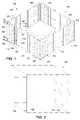
- FIG. 1illustrates a partially broken away perspective view of the four corner portions of the frame of a structure secured to a foundation with a shear panel mounted at each end of each wall of the frame proximate each corner;
- FIG. 2illustrates an exploded perspective view of one of the shear panels of FIG. 1 showing a non-structural layer, an adhesive layer, and a shear layer, wherein the length of the shear layer is longer than the length of the non-structural layer;
- FIG. 3illustrates an enlarged cross-sectional view of the upper portion of one of the shear panels of FIG. 1 taken along the lines 3 - 3 in FIG. 1 and showing the layers of the shear panel in more detail;
- FIG. 4illustrates an enlarged cross-sectional view of the lower portion of one of the shear panels of FIG. 1 taken along the lines 4 - 4 in FIG. 1 and showing the tab layer of the shear panel in more detail;
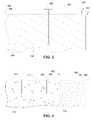
- FIG. 5illustrates a partial perspective view of the frame of a structure secured to a foundation with a shear panel having a tab along a longer horizontal edge and with the height of the shear panel less than the height of the studs forming the walls of the structure.
- FIG. 1is a perspective illustration of a partially framed structure 100 , such as, for example, a residence or a small commercial building.
- the structurecomprises a foundation 110 , which is illustrated as a slab in FIG. 1 .
- the slabis shown in partially broken section in FIG. 1 in order to emphasize the shear panels at the corners of the structure.
- the foundationmay comprise only a perimeter footing or may comprise the above-ground portion of the perimeter walls of a basement.
- a first side wall 120 , a second side wall 122 , a third side wall 124 and a fourth side wall 126are supported by the foundation 110 .
- Each side wallcomprises a lower mudsill 130 , which rests on the upper surface of the foundation.
- the mudsillis preferably aligned with the upper edges of the vertical sides of the foundation so that the mudsill does not extend beyond the edge of the foundation and so that the upper surface of the foundation is not exposed proximate the outer edge of the mudsill.
- the mudsillcomprises wood, such as, for example, a standard 2 ⁇ 4 (actually 1.5 inches by 3.5 inches) structural member having one or more lengths selected to span the length and width of the foundation.
- the mudsillmay also comprise a metallic structural member.
- the mudsill 130supports a plurality of conventional vertical studs 132 , which are spaced apart in a regular conventional manner.
- the studsare preferably spaced so that four adjacent studs provide vertical support for a four-foot by eight-foot panel, with one stud at each vertical edge of the panel and two studs being positioned between the first two studs.
- the vertical studsare doubled every four feet to correspond to the edges of the panels.
- the side wallsmay also include a plurality of cross members 134 as required by relevant building codes.
- a top plate 140is positioned across the tops of the studs.
- the top plateis approximately twice the thickness of the mudsill.
- the top plateadvantageously comprises an upper top plate layer 142 and a lower top plate layer 144 of 2 ⁇ 4 structural wood to provide a thickness of approximately 3 inches.
- the lengths of the vertical studs 132are selected for the height of the walls. For example, when conventional 92.25-inch studs are used, the combined height of the mudsill 130 , the studs and the top plate produce an overall wall height of approximately 96.75 inches, which is approximately 0.75 inch higher than the length of a standard 8-foot wall panel.
- the mudsill 130is advantageously secured to the foundation by conventional devices.
- the mudsillis secured by a plurality of nut and washer combinations 150 , which are attached to bolts embedded in the foundation.
- a plate(not shown) may be included to increase the surface area of the force applied against the top surface of the mudsill.
- the nuts and washerssecure the mudsill to the foundation, the vertical studs 132 of the walls are not secured directly to the foundation. Furthermore, the nuts and washers may not be sufficient to keep the mudsill secured to the foundation under high wind conditions if the walls start to move back and forth.
- Hold-down devicesare available to also connect the studs to the foundation; however, the placement of the hold-down devices with respect to the locations of the studs requires additional labor, and the hold-devices add significant expense to the building construction.
- the system described hereinprovides significant wind protection without adding significantly to the construction costs.
- a plurality of shear panels 160are positioned on each wall 120 , 122 , 124 , 126 proximate to the corners of the foundation 110 .
- Shear panelsare conventionally used in certain regions as protection against movement caused by high winds and earth movement (e.g., movement caused by earthquakes and other seismic events).
- An exemplary conventional shear panelis disclosed, for example, in U.S. Pat. No. 5,768,841 to Swartz et al., which is incorporated by reference herein.
- Such conventional shear panelsare manufactured to have a thickness in a range of approximately 0.5 inch to approximately 0.625 inch so that the shear panel can be installed in lieu of conventional plywood panels on a building structure.
- the conventional shear panelsare not suitable for structures that do not have a corresponding thickness of regular paneling adjacent the shear paneling.
- the thickness of the conventional shear panels on one portion of a wallmay require the remaining portions of the wall to be shimmed with furring strips or the like to achieve a uniform thickness before the finish is applied.
- each shear panel 160 in FIG. 1differs from the patented shear panels by utilizing a rigid non-structural layer 162 that is not as thick as the previously known shear panel.
- the non-structural layeris laminated to a thin shear layer 164 .
- the non-structural layer 162advantageously comprises a thin sheet of medium density fiber board (MDF), plywood, magnesium oxide board, or other suitable material, which is easily handled using conventional construction techniques.
- MDFmedium density fiber board
- the non-structural layeradvantageously has a thickness in a range of approximately 0.0625 inch to approximately 0.25 inch.
- the thickness of the non-structural layeris in a range of approximately 0.0625 inch to approximately 0.1875 inch. More preferably, the thickness of the non-structural layer is about 0.125 inch.
- the non-structural layeris formed as a sheet having a size that conforms with the size of a conventional structural panel.
- the non-structural layeradvantageously has a width of approximately 48 inches and has a length corresponding to the height of the side walls 120 , 122 , 124 , 126 .
- the length of the non-structural layeradvantageously is one of 8 feet, 9 feet, 10 feet or 12 feet.
- the length of the non-structural layermay be advantageously formed in a non-conventional size when the side walls have a non-conventional length.
- the non-structural layer 162 of the shear panel 160is laminated (e.g., bonded) to the thin shear layer 164 .
- the thin shear layercomprises a thin steel sheet or a sheet of another high-strength material having suitable characteristics.
- the steel sheetis preferably coated (e.g., by galvanization, by painting or by other suitable coating processes).
- the steel sheetadvantageously has a thickness in a range of approximately 0.015 inch to approximately 0.060 inch, and preferably has a thickness in a range of approximately 0.0179 inch to approximately 0.0389 inch. More preferably, the steel sheet has a thickness of approximately 0.027 inch, which corresponds to 22 gauge steel.
- the shear layer 164has a width that is approximately the same as the width of the non-structural layer 162 ; however, in preferred embodiments, the width of the shear layer is slightly less than the width of the non-structural layer so that when the shear layer is centered on the surface of the non-structural sheet, the side edges (e.g., the long edges) of the shear layer are inset from the side edges of the non-structural layer.
- the side edges of the shear layermay be inset by approximately 0.0626 inch to approximately 0.125 inch from the side edges of the structural layer so that the potentially sharp edges of the shear layer (e.g., the steel sheet in the preferred embodiment) are not exposed when the shear panel 160 is handled at a construction site.
- the upper edge of the shear layer(the edge of the shorter side to be installed on one of the top plates 140 of the structure 100 ) is also preferably offset by approximately the same amount from the upper edge of the non-structural sheet.
- each shear panel 160is formed by laminating the shear layer 164 to a rear surface (when viewed from the outside of the wall onto which the shear panel is mounted) of the non-structural layer 162 using a suitable adhesive layer 166 .
- the adhesive layeris illustrated as a sheet in FIG. 2 , but the adhesive layer is advantageously formed by rolling, brushing or spraying a liquid adhesive onto a surface of the non-structural panel prior to placement of the shear layer. After applying the shear layer over the adhesive layer, pressure is applied to the three layers so that the shear layer is secured as a substantially flat layer against the non-structural layer.
- the thin shear layeris easily handled and is maintained substantially flat when the shear panel is positioned against the vertical studs 132 .
- the shear panel 160further differs from the conventional shear panel because only an upper portion of the shear layer 164 is bonded to the rear surface of the non-structural layer 162 .
- the shear panelincludes an extended, unbonded portion of the shear layer that forms a tab 170 at the lower end of the shear panel.
- the tabhas a length of approximately 4 inches such that when the non-structural layer has a length of approximately 8 feet (96 inches), the steel layer has an overall length of approximately 100 inches.
- the tabis used to provide wind uplift protection when the shear panel is installed on the structure 100 .
- one of the shear panels 160is positioned at each end of each of the walls 120 , 122 , 124 , 126 at the corners where two walls meet.
- Each shear panelis positioned with the shear layer 164 against the studs 132 .
- the top and the bottom of the non-structural layer 162 of each shear panelare aligned in a conventional manner with the top plate 140 and the mudsill 130 . As illustrated in FIGS. 1 and 4 , when the shear panel is aligned in this manner, the tab 170 of the shear layer extends below the mudsill and is positioned against the bare concrete along the side of the foundation 110 .
- each shear panel 160is secured to the top plate 140 and to the studs 132 using a plurality of fasteners 180 (e.g., nails, screws or the like) suitable to the material comprising the top plate and the studs.
- the tab 170 of the steel shear layer 164is secured to the concrete foundation 110 using a plurality of fasteners 182 suitable for penetrating or engaging concrete, such as, for example, concrete nails, masonry screws, or the like.
- the shear panelsfunction as large straps to secure the corner of one of the walls 120 , 122 , 124 , 126 to the foundation.
- the non-structural layer 162 in the shear panelassures that the steel shear layer is installed substantially flat against the top plate and the studs and is maintained in flat condition after installation.
- each shear panel 160substantially reduces or eliminates any tendency of the side walls to lift from the foundation. Furthermore, the steel layer interconnects the studs, the top plate and the mudsill to provide the rigidity of the conventional shear panel described in the above-referenced patent to Swartz et al., thus reducing any tendency of the side walls to lean away from the pressure of the wind.
- the overall thickness of the shear panel 160is preferably less than approximately 0.1875 inch. Accordingly, conventional exterior wall materials (e.g., insulating boards, lap siding, masonry siding, plaster siding or the like) may be positioned directly over the shear panel. In some installations, a thin layer of shim material may be placed on the first vertical stud 132 adjacent the edge of the shear panel to obviate an abrupt transition in the offset of the wall material being installed over the shear panel and the wall material being installed on an adjacent stud not covered by the shear panel. On subsequent studs, the difference between the thicknesses with and without the underlying shear panel should not require additional shimming.
- conventional exterior wall materialse.g., insulating boards, lap siding, masonry siding, plaster siding or the like
- the difference in thickness caused by the shear panelis not significantly greater than a difference in thickness that may occur in conventional wall systems because of variations in the wall thickness caused by non-uniform studs and caused by non-uniform placements of the studs on the mudsill.
- the tab 170 and the fastening devices 182 extending over the side of the concrete foundation 110are advantageously covered with plaster or another suitable finishing materials when the siding or other finish material is installed on the side walls.
- the improved shear panel 160is easily installed on the structure 100 in accordance with conventional construction techniques.
- the shear paneldoes not require any additional hold-down devices to be placed in the foundation 110 when the concrete is poured.
- the normal number of embedded bolts and nut and washer combinations 150 that secure the mudsill 130 to the foundationare adequate when used in combination with the improved shear panel.
- the shear panelis readily installed by the framers of the structure.
- the shear paneldoes not require any significant adaptation in the procedures used when the outer wall material is installed because the overall thickness of the shear panel is sufficiently thin to allow conventional wall materials to be installed directly over the shear panel. Because of the effectively large size of the “strap” provided by each shear panel, the shear panel provides a substantial benefit in securing the walls of the structure to the foundation during high wind conditions.
- each shear panel 160has the lower tab 170 formed as an extension of one of the edges having the narrower width (e.g., along a 4-foot edge of a 4 foot by eight foot panel). Accordingly, the shorter edges of the shear panel are positioned horizontally. In some circumstances, an architect or contract may choose to position a shear panel with the longer edges of the shear panel horizontally. As illustrated for a structure 200 in FIG. 5 , a shear panel 260 may be constructed with a tab 266 extending along the long edge so that the shear panel may be installed horizontally. Such an installation technique is useful, for example, for longer walls in order to provide additional interconnections to the foundation.
Landscapes
- Engineering & Computer Science (AREA)
- Architecture (AREA)
- Physics & Mathematics (AREA)
- Electromagnetism (AREA)
- Civil Engineering (AREA)
- Structural Engineering (AREA)
- Load-Bearing And Curtain Walls (AREA)
Abstract
Description
Claims (17)
Priority Applications (1)
| Application Number | Priority Date | Filing Date | Title |
|---|---|---|---|
| US11/767,498US7658045B2 (en) | 2007-06-23 | 2007-06-23 | Wall structure for protection against wind-caused uplift |
Applications Claiming Priority (1)
| Application Number | Priority Date | Filing Date | Title |
|---|---|---|---|
| US11/767,498US7658045B2 (en) | 2007-06-23 | 2007-06-23 | Wall structure for protection against wind-caused uplift |
Publications (2)
| Publication Number | Publication Date |
|---|---|
| US20080313995A1 US20080313995A1 (en) | 2008-12-25 |
| US7658045B2true US7658045B2 (en) | 2010-02-09 |
Family
ID=40135054
Family Applications (1)
| Application Number | Title | Priority Date | Filing Date |
|---|---|---|---|
| US11/767,498Active2027-12-09US7658045B2 (en) | 2007-06-23 | 2007-06-23 | Wall structure for protection against wind-caused uplift |
Country Status (1)
| Country | Link |
|---|---|
| US (1) | US7658045B2 (en) |
Cited By (20)
| Publication number | Priority date | Publication date | Assignee | Title |
|---|---|---|---|---|
| US8756896B1 (en) | 2012-12-31 | 2014-06-24 | Specialty Hardware L.P. | Roof panel for protection against airborne threats |
| US20140260074A1 (en)* | 2004-11-09 | 2014-09-18 | Johns Manville | Roofing systems and methods |
| US9316015B1 (en) | 2014-02-21 | 2016-04-19 | Specialty Hardware L.P. | Shelter for protection against wind and blast events |
| US9382709B2 (en)* | 2010-06-08 | 2016-07-05 | Innovative Building Technologies, Llc | Premanufactured structures for constructing buildings |
| US9493940B2 (en) | 2010-06-08 | 2016-11-15 | Innovative Building Technologies, Llc | Slab construction system and method for constructing multi-story buildings using pre-manufactured structures |
| US9909317B2 (en) | 2004-11-09 | 2018-03-06 | Johns Manville | Roofing systems and methods |
| US10041289B2 (en) | 2014-08-30 | 2018-08-07 | Innovative Building Technologies, Llc | Interface between a floor panel and a panel track |
| US10260250B2 (en) | 2014-08-30 | 2019-04-16 | Innovative Building Technologies, Llc | Diaphragm to lateral support coupling in a structure |
| US10323428B2 (en) | 2017-05-12 | 2019-06-18 | Innovative Building Technologies, Llc | Sequence for constructing a building from prefabricated components |
| US10329764B2 (en) | 2014-08-30 | 2019-06-25 | Innovative Building Technologies, Llc | Prefabricated demising and end walls |
| US10364572B2 (en) | 2014-08-30 | 2019-07-30 | Innovative Building Technologies, Llc | Prefabricated wall panel for utility installation |
| US10487493B2 (en) | 2017-05-12 | 2019-11-26 | Innovative Building Technologies, Llc | Building design and construction using prefabricated components |
| US10508442B2 (en) | 2016-03-07 | 2019-12-17 | Innovative Building Technologies, Llc | Floor and ceiling panel for slab-free floor system of a building |
| US10676923B2 (en) | 2016-03-07 | 2020-06-09 | Innovative Building Technologies, Llc | Waterproofing assemblies and prefabricated wall panels including the same |
| US10724228B2 (en) | 2017-05-12 | 2020-07-28 | Innovative Building Technologies, Llc | Building assemblies and methods for constructing a building using pre-assembled floor-ceiling panels and walls |
| US10900224B2 (en) | 2016-03-07 | 2021-01-26 | Innovative Building Technologies, Llc | Prefabricated demising wall with external conduit engagement features |
| US10961710B2 (en) | 2016-03-07 | 2021-03-30 | Innovative Building Technologies, Llc | Pre-assembled wall panel for utility installation |
| US11054148B2 (en) | 2014-08-30 | 2021-07-06 | Innovative Building Technologies, Llc | Heated floor and ceiling panel with a corrugated layer for modular use in buildings |
| US11098475B2 (en) | 2017-05-12 | 2021-08-24 | Innovative Building Technologies, Llc | Building system with a diaphragm provided by pre-fabricated floor panels |
| US12297076B2 (en) | 2018-11-14 | 2025-05-13 | Innovative Building Technologies, Llc | Modular stairwell and elevator shaft system and method |
Families Citing this family (3)
| Publication number | Priority date | Publication date | Assignee | Title |
|---|---|---|---|---|
| US20110225915A1 (en)* | 2007-12-20 | 2011-09-22 | Specialty Hardware L.P. | Energy absorbing blast wall for building structure |
| US8079188B2 (en)* | 2007-12-20 | 2011-12-20 | Specialty Hardware L.P. | Energy absorbing blast wall for building structure |
| US20110027100A1 (en)* | 2009-07-30 | 2011-02-03 | Daniel Francis Cummane | Mobile wind power station |
Citations (21)
| Publication number | Priority date | Publication date | Assignee | Title |
|---|---|---|---|---|
| US3302349A (en)* | 1963-03-25 | 1967-02-07 | Zugehor Alexander | Shelter reinforcement |
| US3755982A (en)* | 1971-07-13 | 1973-09-04 | C Schmidt | Building panels |
| US4122203A (en)* | 1978-01-09 | 1978-10-24 | Stahl Joel S | Fire protective thermal barriers for foam plastics |
| CH612239A5 (en) | 1977-01-20 | 1979-07-13 | Keller Ziegeleien | Slab for an insulating roof substructure |
| US4356675A (en)* | 1980-10-24 | 1982-11-02 | United States Gypsum Company | Tie-down runner for mobile home wall construction |
| US5034085A (en)* | 1985-05-03 | 1991-07-23 | Brauchl-Fertighaus Vertriebsgesellschaft M.B.H. & Co. Kg | Method of making a composite wall structure and a building prefabricated therewith |
| US5402615A (en)* | 1992-11-13 | 1995-04-04 | International Copper Association, Ltd. | Fire retardant barrier system and method |
| US5749187A (en)* | 1994-09-02 | 1998-05-12 | Yoshino Gypsum Co., Ltd. | Partition wall |
| US5768841A (en) | 1993-04-14 | 1998-06-23 | Swartz & Kulpa, Structural Design And Engineering | Wallboard structure |
| US5927032A (en) | 1997-04-25 | 1999-07-27 | Record; Grant C. | Insulated building panel with a unitary shear resistance connector array |
| US20010032425A1 (en)* | 2000-02-03 | 2001-10-25 | Terry Leonard R. | Solid monolithic concrete insulated wall system |
| US6412247B1 (en) | 1996-03-04 | 2002-07-02 | National Gypsum Properties, Llc | Composite structural member and wall assembly method |
| US20020095896A1 (en)* | 1997-06-12 | 2002-07-25 | James R. Cypher | Diaphragm with perimeter edging on structural panels |
| US20050086905A1 (en) | 2003-10-22 | 2005-04-28 | Dietrich Industries, Inc. | Shear wall panel |
| US6901713B2 (en) | 2002-01-03 | 2005-06-07 | Erich Jason Axsom | Multipurpose composite wallboard panel |
| US20060143998A1 (en)* | 1997-04-14 | 2006-07-06 | Timmerman Timothy L | Lateral force resisting system |
| US7100342B2 (en)* | 2002-07-18 | 2006-09-05 | Wynn Peter Holloway | Building panel |
| US20070044407A1 (en) | 2005-08-30 | 2007-03-01 | Specialty Hardware L.P. | Fire-retardant cementitious shear board having metal backing with tab for use as underlayment panel for floor or roof |
| US20080120932A1 (en)* | 2006-09-22 | 2008-05-29 | Paradis Duane R | Polymer-based composite structural sheathing board and wall and/or ceilling system |
| US20090094909A1 (en)* | 2007-10-11 | 2009-04-16 | Modular Concepts Corporation | Enclosure panel isolation system |
| US7607271B2 (en)* | 2004-11-09 | 2009-10-27 | Johns Manville | Prefabricated multi-layer roofing panel and system |
- 2007
- 2007-06-23USUS11/767,498patent/US7658045B2/enactiveActive
Patent Citations (21)
| Publication number | Priority date | Publication date | Assignee | Title |
|---|---|---|---|---|
| US3302349A (en)* | 1963-03-25 | 1967-02-07 | Zugehor Alexander | Shelter reinforcement |
| US3755982A (en)* | 1971-07-13 | 1973-09-04 | C Schmidt | Building panels |
| CH612239A5 (en) | 1977-01-20 | 1979-07-13 | Keller Ziegeleien | Slab for an insulating roof substructure |
| US4122203A (en)* | 1978-01-09 | 1978-10-24 | Stahl Joel S | Fire protective thermal barriers for foam plastics |
| US4356675A (en)* | 1980-10-24 | 1982-11-02 | United States Gypsum Company | Tie-down runner for mobile home wall construction |
| US5034085A (en)* | 1985-05-03 | 1991-07-23 | Brauchl-Fertighaus Vertriebsgesellschaft M.B.H. & Co. Kg | Method of making a composite wall structure and a building prefabricated therewith |
| US5402615A (en)* | 1992-11-13 | 1995-04-04 | International Copper Association, Ltd. | Fire retardant barrier system and method |
| US5768841A (en) | 1993-04-14 | 1998-06-23 | Swartz & Kulpa, Structural Design And Engineering | Wallboard structure |
| US5749187A (en)* | 1994-09-02 | 1998-05-12 | Yoshino Gypsum Co., Ltd. | Partition wall |
| US6412247B1 (en) | 1996-03-04 | 2002-07-02 | National Gypsum Properties, Llc | Composite structural member and wall assembly method |
| US20060143998A1 (en)* | 1997-04-14 | 2006-07-06 | Timmerman Timothy L | Lateral force resisting system |
| US5927032A (en) | 1997-04-25 | 1999-07-27 | Record; Grant C. | Insulated building panel with a unitary shear resistance connector array |
| US20020095896A1 (en)* | 1997-06-12 | 2002-07-25 | James R. Cypher | Diaphragm with perimeter edging on structural panels |
| US20010032425A1 (en)* | 2000-02-03 | 2001-10-25 | Terry Leonard R. | Solid monolithic concrete insulated wall system |
| US6901713B2 (en) | 2002-01-03 | 2005-06-07 | Erich Jason Axsom | Multipurpose composite wallboard panel |
| US7100342B2 (en)* | 2002-07-18 | 2006-09-05 | Wynn Peter Holloway | Building panel |
| US20050086905A1 (en) | 2003-10-22 | 2005-04-28 | Dietrich Industries, Inc. | Shear wall panel |
| US7607271B2 (en)* | 2004-11-09 | 2009-10-27 | Johns Manville | Prefabricated multi-layer roofing panel and system |
| US20070044407A1 (en) | 2005-08-30 | 2007-03-01 | Specialty Hardware L.P. | Fire-retardant cementitious shear board having metal backing with tab for use as underlayment panel for floor or roof |
| US20080120932A1 (en)* | 2006-09-22 | 2008-05-29 | Paradis Duane R | Polymer-based composite structural sheathing board and wall and/or ceilling system |
| US20090094909A1 (en)* | 2007-10-11 | 2009-04-16 | Modular Concepts Corporation | Enclosure panel isolation system |
Non-Patent Citations (2)
| Title |
|---|
| Cem-Steel. Datasheet [online]. U.S. Architectural Products, Inc., Jul. 10, 2004. [retrieved on Sep. 16, 2005]. Retrieved from the Internet: . [62 pages]. |
| Cem-Steel. Datasheet [online]. U.S. Architectural Products, Inc., Jul. 10, 2004. [retrieved on Sep. 16, 2005]. Retrieved from the Internet: <URL: http://architecturalproducts.com/cemsteel.htm>. [62 pages]. |
Cited By (26)
| Publication number | Priority date | Publication date | Assignee | Title |
|---|---|---|---|---|
| US9404261B2 (en)* | 2004-11-09 | 2016-08-02 | Johns Manville | Roofing systems and methods |
| US20140260074A1 (en)* | 2004-11-09 | 2014-09-18 | Johns Manville | Roofing systems and methods |
| US10087634B2 (en) | 2004-11-09 | 2018-10-02 | Johns Manville | Roofing systems and methods |
| US9909317B2 (en) | 2004-11-09 | 2018-03-06 | Johns Manville | Roofing systems and methods |
| US10190309B2 (en) | 2010-06-08 | 2019-01-29 | Innovative Building Technologies, Llc | Slab construction system and method for constructing multi-story buildings using pre-manufactured structures |
| US9382709B2 (en)* | 2010-06-08 | 2016-07-05 | Innovative Building Technologies, Llc | Premanufactured structures for constructing buildings |
| US9493940B2 (en) | 2010-06-08 | 2016-11-15 | Innovative Building Technologies, Llc | Slab construction system and method for constructing multi-story buildings using pre-manufactured structures |
| US10145103B2 (en)* | 2010-06-08 | 2018-12-04 | Innovative Building Technologies, Llc | Premanufactured structures for constructing buildings |
| US8756896B1 (en) | 2012-12-31 | 2014-06-24 | Specialty Hardware L.P. | Roof panel for protection against airborne threats |
| US9316015B1 (en) | 2014-02-21 | 2016-04-19 | Specialty Hardware L.P. | Shelter for protection against wind and blast events |
| US10329764B2 (en) | 2014-08-30 | 2019-06-25 | Innovative Building Technologies, Llc | Prefabricated demising and end walls |
| US10260250B2 (en) | 2014-08-30 | 2019-04-16 | Innovative Building Technologies, Llc | Diaphragm to lateral support coupling in a structure |
| US10975590B2 (en) | 2014-08-30 | 2021-04-13 | Innovative Building Technologies, Llc | Diaphragm to lateral support coupling in a structure |
| US10041289B2 (en) | 2014-08-30 | 2018-08-07 | Innovative Building Technologies, Llc | Interface between a floor panel and a panel track |
| US10364572B2 (en) | 2014-08-30 | 2019-07-30 | Innovative Building Technologies, Llc | Prefabricated wall panel for utility installation |
| US11060286B2 (en) | 2014-08-30 | 2021-07-13 | Innovative Building Technologies, Llc | Prefabricated wall panel for utility installation |
| US11054148B2 (en) | 2014-08-30 | 2021-07-06 | Innovative Building Technologies, Llc | Heated floor and ceiling panel with a corrugated layer for modular use in buildings |
| US10508442B2 (en) | 2016-03-07 | 2019-12-17 | Innovative Building Technologies, Llc | Floor and ceiling panel for slab-free floor system of a building |
| US10676923B2 (en) | 2016-03-07 | 2020-06-09 | Innovative Building Technologies, Llc | Waterproofing assemblies and prefabricated wall panels including the same |
| US10900224B2 (en) | 2016-03-07 | 2021-01-26 | Innovative Building Technologies, Llc | Prefabricated demising wall with external conduit engagement features |
| US10961710B2 (en) | 2016-03-07 | 2021-03-30 | Innovative Building Technologies, Llc | Pre-assembled wall panel for utility installation |
| US10323428B2 (en) | 2017-05-12 | 2019-06-18 | Innovative Building Technologies, Llc | Sequence for constructing a building from prefabricated components |
| US10724228B2 (en) | 2017-05-12 | 2020-07-28 | Innovative Building Technologies, Llc | Building assemblies and methods for constructing a building using pre-assembled floor-ceiling panels and walls |
| US10487493B2 (en) | 2017-05-12 | 2019-11-26 | Innovative Building Technologies, Llc | Building design and construction using prefabricated components |
| US11098475B2 (en) | 2017-05-12 | 2021-08-24 | Innovative Building Technologies, Llc | Building system with a diaphragm provided by pre-fabricated floor panels |
| US12297076B2 (en) | 2018-11-14 | 2025-05-13 | Innovative Building Technologies, Llc | Modular stairwell and elevator shaft system and method |
Also Published As
| Publication number | Publication date |
|---|---|
| US20080313995A1 (en) | 2008-12-25 |
Similar Documents
| Publication | Publication Date | Title |
|---|---|---|
| US7658045B2 (en) | Wall structure for protection against wind-caused uplift | |
| US8307608B2 (en) | Modular panel wall assemblies | |
| US8875445B2 (en) | Light weight modular units for staggered stacked building system | |
| US8186115B2 (en) | Modular panel assemblies for building foundations | |
| US8769891B2 (en) | Building method using multi-storey panels | |
| US20090077916A1 (en) | Composite wall system | |
| US5634315A (en) | Buildings method of construction | |
| EP0006756B1 (en) | Load bearing composite panel | |
| US8359799B2 (en) | Building module, a method for making same, and a method for using same to construct a building | |
| US5724782A (en) | System and method for constructing buildings (and other structures) capable of withstanding substantial natural forces | |
| US4335558A (en) | Prefabricated polygonal building | |
| US11155977B2 (en) | Portal frame with lap joint for moment resistance | |
| US4464873A (en) | Wall panel system | |
| US20140157706A1 (en) | Formed Stud with Integral Diaphragm Section | |
| AU2019204859B2 (en) | Inter Partes Wall Module | |
| WO2008007325A2 (en) | Building method | |
| US11203865B2 (en) | Beam and bolting construction system and method | |
| JP7100378B2 (en) | Height-adjustable external seismic retrofitting device | |
| US20040177576A1 (en) | Basement wall construction | |
| AU2005312430A1 (en) | Bracing panel | |
| RU45416U1 (en) | SYSTEM OF EXTERNAL HEATING OF THE BUILDING "THERMOSHEELS" | |
| RU107204U1 (en) | OVERLAPPING FOR WOODEN BUILDING (OPTIONS) | |
| CA3118261A1 (en) | Portal frame with lap joint for moment resistance | |
| JP4132405B2 (en) | building | |
| WO2005007983A1 (en) | A building connector , joist hanger, ventilation packer and method of building construction |
Legal Events
| Date | Code | Title | Description |
|---|---|---|---|
| AS | Assignment | Owner name:SPECIALTY HARDWARE L.P., CALIFORNIA Free format text:ASSIGNMENT OF ASSIGNORS INTEREST;ASSIGNORS:ELLIOTT, A. CARLETON;HOLCOMB, KELLY P.;REEL/FRAME:019471/0169 Effective date:20070618 Owner name:SPECIALTY HARDWARE L.P.,CALIFORNIA Free format text:ASSIGNMENT OF ASSIGNORS INTEREST;ASSIGNORS:ELLIOTT, A. CARLETON;HOLCOMB, KELLY P.;REEL/FRAME:019471/0169 Effective date:20070618 | |
| STCF | Information on status: patent grant | Free format text:PATENTED CASE | |
| CC | Certificate of correction | ||
| AS | Assignment | Owner name:SPECIALTY HARDWARE L.P., CALIFORNIA Free format text:ASSIGNMENT OF ASSIGNORS INTEREST;ASSIGNORS:SWARTZ, ALLAN J.;KULPA, GREGORY;SIGNING DATES FROM 20100813 TO 20100904;REEL/FRAME:025472/0956 | |
| FPAY | Fee payment | Year of fee payment:4 | |
| FPAY | Fee payment | Year of fee payment:8 | |
| AS | Assignment | Owner name:SPECIALTY HARDWARE, LLC, ARIZONA Free format text:ASSIGNMENT OF ASSIGNORS INTEREST;ASSIGNOR:SPECIALTY HARDWARE L.P.;REEL/FRAME:045019/0788 Effective date:20180117 | |
| MAFP | Maintenance fee payment | Free format text:PAYMENT OF MAINTENANCE FEE, 12TH YR, SMALL ENTITY (ORIGINAL EVENT CODE: M2553); ENTITY STATUS OF PATENT OWNER: SMALL ENTITY Year of fee payment:12 |