US7657628B1 - External processor for a distributed network access system - Google Patents
External processor for a distributed network access systemDownload PDFInfo
- Publication number
- US7657628B1 US7657628B1US09/723,501US72350100AUS7657628B1US 7657628 B1US7657628 B1US 7657628B1US 72350100 AUS72350100 AUS 72350100AUS 7657628 B1US7657628 B1US 7657628B1
- Authority
- US
- United States
- Prior art keywords
- service
- external processor
- pad
- controller
- network
- Prior art date
- Legal status (The legal status is an assumption and is not a legal conclusion. Google has not performed a legal analysis and makes no representation as to the accuracy of the status listed.)
- Expired - Lifetime, expires
Links
Images


Classifications
- H—ELECTRICITY
- H04—ELECTRIC COMMUNICATION TECHNIQUE
- H04Q—SELECTING
- H04Q3/00—Selecting arrangements
- H04Q3/0016—Arrangements providing connection between exchanges
- H04Q3/0025—Provisions for signalling
- G—PHYSICS
- G06—COMPUTING OR CALCULATING; COUNTING
- G06F—ELECTRIC DIGITAL DATA PROCESSING
- G06F11/00—Error detection; Error correction; Monitoring
- G06F11/07—Responding to the occurrence of a fault, e.g. fault tolerance
- G06F11/16—Error detection or correction of the data by redundancy in hardware
- G06F11/20—Error detection or correction of the data by redundancy in hardware using active fault-masking, e.g. by switching out faulty elements or by switching in spare elements
- G06F11/202—Error detection or correction of the data by redundancy in hardware using active fault-masking, e.g. by switching out faulty elements or by switching in spare elements where processing functionality is redundant
- G06F11/2023—Failover techniques
- G06F11/2028—Failover techniques eliminating a faulty processor or activating a spare
- H—ELECTRICITY
- H04—ELECTRIC COMMUNICATION TECHNIQUE
- H04L—TRANSMISSION OF DIGITAL INFORMATION, e.g. TELEGRAPHIC COMMUNICATION
- H04L12/00—Data switching networks
- H04L12/02—Details
- H04L12/16—Arrangements for providing special services to substations
- H04L12/18—Arrangements for providing special services to substations for broadcast or conference, e.g. multicast
- H04L12/185—Arrangements for providing special services to substations for broadcast or conference, e.g. multicast with management of multicast group membership
- H—ELECTRICITY
- H04—ELECTRIC COMMUNICATION TECHNIQUE
- H04L—TRANSMISSION OF DIGITAL INFORMATION, e.g. TELEGRAPHIC COMMUNICATION
- H04L12/00—Data switching networks
- H04L12/28—Data switching networks characterised by path configuration, e.g. LAN [Local Area Networks] or WAN [Wide Area Networks]
- H04L12/2854—Wide area networks, e.g. public data networks
- H04L12/2856—Access arrangements, e.g. Internet access
- H04L12/2869—Operational details of access network equipments
- H04L12/2898—Subscriber equipments
- H—ELECTRICITY
- H04—ELECTRIC COMMUNICATION TECHNIQUE
- H04L—TRANSMISSION OF DIGITAL INFORMATION, e.g. TELEGRAPHIC COMMUNICATION
- H04L47/00—Traffic control in data switching networks
- H04L47/10—Flow control; Congestion control
- H04L47/20—Traffic policing
- H—ELECTRICITY
- H04—ELECTRIC COMMUNICATION TECHNIQUE
- H04L—TRANSMISSION OF DIGITAL INFORMATION, e.g. TELEGRAPHIC COMMUNICATION
- H04L67/00—Network arrangements or protocols for supporting network services or applications
- H—ELECTRICITY
- H04—ELECTRIC COMMUNICATION TECHNIQUE
- H04L—TRANSMISSION OF DIGITAL INFORMATION, e.g. TELEGRAPHIC COMMUNICATION
- H04L69/00—Network arrangements, protocols or services independent of the application payload and not provided for in the other groups of this subclass
- H04L69/16—Implementation or adaptation of Internet protocol [IP], of transmission control protocol [TCP] or of user datagram protocol [UDP]
- H—ELECTRICITY
- H04—ELECTRIC COMMUNICATION TECHNIQUE
- H04L—TRANSMISSION OF DIGITAL INFORMATION, e.g. TELEGRAPHIC COMMUNICATION
- H04L9/00—Cryptographic mechanisms or cryptographic arrangements for secret or secure communications; Network security protocols
- H04L9/40—Network security protocols
- G—PHYSICS
- G06—COMPUTING OR CALCULATING; COUNTING
- G06F—ELECTRIC DIGITAL DATA PROCESSING
- G06F11/00—Error detection; Error correction; Monitoring
- G06F11/07—Responding to the occurrence of a fault, e.g. fault tolerance
- G06F11/16—Error detection or correction of the data by redundancy in hardware
- G06F11/20—Error detection or correction of the data by redundancy in hardware using active fault-masking, e.g. by switching out faulty elements or by switching in spare elements
- G06F11/202—Error detection or correction of the data by redundancy in hardware using active fault-masking, e.g. by switching out faulty elements or by switching in spare elements where processing functionality is redundant
- G06F11/2023—Failover techniques
- G06F11/2033—Failover techniques switching over of hardware resources
- G—PHYSICS
- G06—COMPUTING OR CALCULATING; COUNTING
- G06F—ELECTRIC DIGITAL DATA PROCESSING
- G06F11/00—Error detection; Error correction; Monitoring
- G06F11/07—Responding to the occurrence of a fault, e.g. fault tolerance
- G06F11/16—Error detection or correction of the data by redundancy in hardware
- G06F11/20—Error detection or correction of the data by redundancy in hardware using active fault-masking, e.g. by switching out faulty elements or by switching in spare elements
- G06F11/202—Error detection or correction of the data by redundancy in hardware using active fault-masking, e.g. by switching out faulty elements or by switching in spare elements where processing functionality is redundant
- G06F11/2043—Error detection or correction of the data by redundancy in hardware using active fault-masking, e.g. by switching out faulty elements or by switching in spare elements where processing functionality is redundant where the redundant components share a common memory address space
- G—PHYSICS
- G06—COMPUTING OR CALCULATING; COUNTING
- G06F—ELECTRIC DIGITAL DATA PROCESSING
- G06F11/00—Error detection; Error correction; Monitoring
- G06F11/07—Responding to the occurrence of a fault, e.g. fault tolerance
- G06F11/16—Error detection or correction of the data by redundancy in hardware
- G06F11/20—Error detection or correction of the data by redundancy in hardware using active fault-masking, e.g. by switching out faulty elements or by switching in spare elements
- G06F11/2097—Error detection or correction of the data by redundancy in hardware using active fault-masking, e.g. by switching out faulty elements or by switching in spare elements maintaining the standby controller/processing unit updated
- H—ELECTRICITY
- H04—ELECTRIC COMMUNICATION TECHNIQUE
- H04L—TRANSMISSION OF DIGITAL INFORMATION, e.g. TELEGRAPHIC COMMUNICATION
- H04L67/00—Network arrangements or protocols for supporting network services or applications
- H04L67/50—Network services
- H04L67/56—Provisioning of proxy services
- H04L67/568—Storing data temporarily at an intermediate stage, e.g. caching
Definitions
- the Internetcan generally be defined as a worldwide collection of heterogeneous communication networks and associated gateways, bridges and routers that all employ the TCP/IP (Transport Control Protocol/Internet Protocol) suite of protocols to communicate data packets between a source and one or more destinations.
- TCP/IPTransmission Control Protocol/Internet Protocol
- the TCP/IP suite of protocolscorresponds to layers 3 and 4 (the network and transport layers, respectively) of the seven-layer International Organization for Standardization Open Systems Interconnection (ISO/OSI) reference model, which provides a convenient framework for discussing communication protocols.
- ISO/OSI reference modelfurther includes physical and link layers (layers 1 and 2, respectively) below the network and transport layers, and session, presentation, and application layers (layers 5 through 7, respectively) above the network and transport layers.
- router architectureis generally monolithic and proprietary. Consequently, the range of data services that a service provider can offer in addition to basic packet routing is limited by the control software offered by router vendors. In addition, the packet-processing throughput of a router is generally limited by its originally installed processing hardware and cannot be expanded or extended without replacement of the entire router.
- the monolithic and proprietary design of conventional routerspresents a number of problems addressed by the present invention.
- conventional monolithic router designsalso have limited flexibility and extensibility.
- the present inventionrecognizes that it would be desirable, in view of the rapid growth of Internet traffic, to dynamically provision, configure, and/or reallocate access capacity to IP-based services. Because access capacity is necessarily limited and providing additional access capacity is a major cost component of networks, the enforcement of intelligent admission control policies and provision of differing qualities of service is vital to the efficient utilization of available access capacity.
- conventional edge routersare not capable of classifying a wide variety of traffic types while enforcing policy controls or of responding to dynamic requests for capacity, and this functionality is difficult to incorporate within currently deployed monolithic edge routers.
- the present inventionaccordingly recognizes that it would be desirable to provide the above as well as additional policy control, network monitoring, diagnostic, and security services in commercialized hardware, while permitting these services to be tailored to meet the needs of individual customers and service providers.
- the present inventionrecognizes that it would be desirable to introduce a new network access architecture that addresses and overcomes the limitations of conventional monolithic router architectures.
- the external processorincludes a service controller that provides at least one service for network traffic, a message processor that processes network messages for service processing by the service controller, and a programmable access device controller that programs the programmable access device in response to service controller processing. It is advantageous for the external processor to include primary and secondary service controllers for a particular service so that, if the primary service controller fails, the secondary service controller can support the particular service on the programmable access device.
- the service controllerfurther includes a reporting processor that provides an interface through which reporting messages received from the programmable access device can be communicated to the service controller and a signaling controller that forwards signaling messages to the network to establish requested network connections.
- the external processorpreferably further supports a service policy interface through which the service controller can request policy decisions from a possibly remote policy server.
- FIG. 1Bis a metropolitan view of an Internet service provider network in accordance with the present invention.
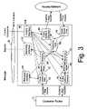
- FIG. 3is a more detailed block diagram of an exemplary embodiment of a programmable access device (PAD) in accordance with the present invention
- FIG. 4is a more detailed block diagram of an exemplary embodiment of an external processor in accordance with the present invention.
- FIG. 6illustrates exemplary signaling in a network access system in accordance with the present invention to support service reservation utilizing Resource Reservation Protocol (RSVP);
- RSVPResource Reservation Protocol
- FIG. 7Edepicts exemplary signaling in a network access system in accordance with the present invention in response to an authorized request for a TCP session
- FIG. 8Aillustrates exemplary signaling in a network access system in accordance with the present invention to establish a UDP (User Datagram Protocol) session having an enhanced quality of service (QoS) path;
- UDPUser Datagram Protocol
- QoSenhanced quality of service
- FIG. 8Cillustrates exemplary signaling in a network access system in accordance with the present invention to tear down a UDP session that has timed out;
- FIG. 9Billustrates exemplary signaling in a network access system in accordance with the present invention during SIP call termination
- FIG. 9Cdepicts exemplary signaling in a network access system in accordance with the present invention to conclude a SIP call following detection of a time out by the network;
- FIG. 9Dillustrates exemplary signaling in a network access system in accordance with the present invention to conclude a SIP call following detection of a time out by the programmable access device
- FIG. 9Edepicts exemplary signaling in a network access system in accordance with the present invention during SIP call negotiation
- FIG. 10Adepicts exemplary signaling in a network access system in accordance with the present invention to authorize registration of a multicast group
- FIG. 10Billustrates exemplary signaling in a network access system in accordance with the present invention in response to an unauthorized attempt to register a multicast group
- FIG. 10Cdepicts exemplary signaling in a network access system in accordance with the present invention in response to an authorized multicast group membership query
- FIG. 10Edepicts exemplary signaling in a network access system in accordance with the present invention in response to receipt of authorized multicast packets from outside the network;
- FIG. 10Fillustrates exemplary signaling in a network access system in accordance with the present invention in response to receipt of unauthorized multicast packets from outside the network;
- communication network 30may be coupled to equipment of a number of customers (one of which is represented by a customer router 32 ) by an access line 34 .
- access line 34may employ any of a number of commonly utilized transport network technologies, such as Ethernet, SONET, ATM and frame relay, and may further include unillustrated aggregation hardware.
- communication network 30includes one or more core communication links 38 (e.g., trunk lines) coupled to one or more core routers 36 .
- customer router 32does not interface to communication network 30 via a monolithic, proprietary edge router. Instead, customer equipment, such as customer router 32 , interfaces with communication network 30 via a network access system 31 that distributes the functions of traditional edge routers (as well as additional functionality) among three logical modules: a programmable access device (PAD) 40 , an external processor 42 , and an access router 44 .
- PIDprogrammable access device
- basic routing of packets between input and output ports of the access networkis performed by access router 44 by reference to forwarding table 50 as determined by Exterior Gateway Protocol (EGP) and Interior Gateway Protocol (IGP) routing tables 52 and 54 .
- EGPExterior Gateway Protocol
- IGPInterior Gateway Protocol
- forwarding and generic traffic conditioning functionssuch as marking, policing, monitoring, shaping, and filtering
- service functionssuch as message interpretation, signaling, admission control, and policy invocation, are implemented in external processor 42 .
- incoming and outgoing packetsare typically communicated between core communication links 38 and customer router 32 via PAD 40 , access router 44 , and core router 36 (and optionally additional switching the access network, such as an ATM or MPLS switch 60 ).
- PAD 40detects packet flows for which additional services are required, PAD 40 passes appropriate messages to external processor 42 for service processing via a Message, Reporting, and Control Interface (MCRI) 58 , which can be accessed via an Application Programming Interface (API) on PAD 40 and external processor 42 .
- MCRIMessage, Reporting, and Control Interface
- APIApplication Programming Interface
- Distributing functionality between access router 44 , PAD 40 , and external processor 42 in this mannergives the service provider (or even third parties) the freedom to extend and modify existing services, create new services, or add more processing power to external processor 42 without adversely affecting the forwarding performance of PAD 40 and the routing performance or functionality of access router 44 .
- the service providercan define policy rules in the policy database 46 of one or more policy servers 48 (also referred to as a policy decision point (PDP)). Policy server 48 then makes policy decisions that control the functionality and operation of PAD 40 and external processor 42 by reference to the policy rules stored in policy database 46 . Policy server 48 communicates policy decisions and associated configuration parameters for external processor 42 and/or PAD 40 to external processor 42 via a Service Policy Interface (SPI) 56 , which can be accessed, for example, via an API on policy server 48 and external processor 42 .
- SPIService Policy Interface
- Communication via SPI 56can employ any of a number of policy query protocols, including Common Open Policy Service (COPS) and Lightweight Directory Access Protocol (LDAP), which are respectively defined by Internet Engineering Task Force (IETF) RFCs 2748 and 2251 , which are incorporated herein by reference.
- External processor 42relays configuration parameters for PAD 40 , if any, to PAD 40 via MCRI 58 .
- network access system 31 of the present inventionpermits flexibility in the placement and implementation of network switching.
- an ATM or MPLS (Multi-Protocol Label Switching) networkcan be utilized to couple one or more PADs 40 to port of an access router 44 through an ATM or MPLS switch 60 , thereby permitting signaling and policing functional blocks 62 and 64 to be implemented separately from access router 44 .
- signalingis implemented by access router 44
- switch 60can be eliminated.
- Switch 60can also alternatively be interposed between access router 44 and core router 36 an aggregation switch.
- access router 44may be implemented by an external processor 42 running routing software controlling a large PAD 40 .
- PAD 40is a programmable access device containing required forwarding and packet classification functions along with other optional traffic conditioning functional modules that implement any desired combination of marking, policing, monitoring, and shaping for incoming and outgoing packets.
- PAD 40is implemented as a combination of software and conventional router hardware that cooperate to provide the functionality of the illustrated modules. (In FIG. 3 , dashed line illustration is utilized to indicate optional functional modules.)
- the functional modules of PAD 40are logically arranged in incoming (e.g., from customer router 32 ) and outgoing (e.g., to customer router 32 ) traffic paths, with the incoming path including packet header filter 80 , marker/policer 82 , monitor(s) 84 , forwarding table 86 , and output buffers and scheduler 88 .
- the outgoing pathsimilarly includes packet header filter 90 , forwarding table 86 , monitor(s) 92 , marker/shaper 94 , and output buffers and scheduler 96 .
- the functions of all of these functional modulescan be independently configured or programmed by an external processor 42 through MCRI 58 .
- Incoming packets received from customer router 34 at the external interface of PAD 40are first processed by packet header filter 80 , which distinguishes between various message types using any one or a combination of the protocol type, Source Address (SA), Destination Address (DA), Type Of Service (TOS), Diffserv Codepoint (DSCP), Source Port (SP), Destination Port (DP), and other fields of a packet (e.g., layer 4 and higher layer fields such as the SYN, ACK, RST, and FIN TCP flags) upon which packet header filter 80 is configured to filter.
- packet header filter 80has the ability to identify higher layer (i.e., layer 4-7) message types or specific fields and forward those messages from/to external processor 42 based on the configured filter parameters.
- packet header filter 80directs the packet either to an external processor 42 via message interface 100 or to a specific marker/policer 82 . It should also be noted that message interface 100 may also inject a packet specified by external processor 42 into either of packet header filters 80 and 90 .
- marker/policer 82may set bits in the Differentiated Services (DiffServ)/TOS byte in the IP packet header, and/or the 3-bit MPLS experimental field, and/or the 20-bit MPLS label field, and/or other fields as configured by control interface 104 for that particular packet stream.
- DiffServDifferentiated Services
- Forwarding table 86After processing by packet header filter 80 (and optionally by marker/policer 82 and monitors 84 ), incoming packets are processed by forwarding table 86 .
- Forwarding table 86maintains entries for each forwarding path, where each forwarding path is represented by packet flow attributes, such as DA, SA, TOS, PT, SP, DP, the incoming port, and the corresponding output port to which PAD 40 forwards the packet through the access network toward access router 44 . Utilizing these forwarding table entries, forwarding table 86 forwards packets to the appropriate output ports and passes the packets to output buffers and scheduler 88 .
- Output buffers and scheduler 88buffer packets ready for transmission over communication network 30 and schedule the transmission of such packets.
- the buffering within output buffers and scheduler 88which can comprise a single buffer or preferably multiple buffers, is preferably configured to support multiple QoS classes, or even QoS for each individual flow. For example, a percentage or a fixed amount of buffer space can be assigned to a queue serving a generic class of traffic or a particular traffic flow classified by DA, SA, TOS, PT, SP and/or DP.
- the packet schedulerthen applies weighted round robin and/or other algorithms to the multiple queues multiplexing the different traffic flows.
- Buffers and scheduler 88can also apply CBQ (Class-based Queuing), WFQ (Weighted Fair Queuing), WRR (Weighted Round Robin) or other link sharing algorithms to optimize communication.
- CBQClass-based Queuing
- WFQWeighted Fair Queuing
- WRRWeighted Round Robin
- the outgoing path through PAD 40is similar to the incoming path, except for the inclusion of marker/shaper 94 in lieu of marker/policer 82 .
- marker/shaper 94discards nonconforming packets, sends marked packets to appropriate output buffers for the various queues serving different QoS classes for individual flows within output buffers and scheduler 96 to control the delay, jitter and loss of an outgoing packet flow, or simply counts non-conforming packets.
- a PAD 40 in accordance with the present inventioncan be deployed at a number of locations in a network to perform traffic management and policy control.
- a PAD 40can be placed in a customer access network (e.g., fiber, xDSL, cable modem, WAP (Wireless Access Protocol), etc.) connecting customer equipment to a provider network controlled by regionally located external processors 42 .
- a PAD 40can be deployed at a service provider's Point of Presence (POP), interfacing with a customer site over a private line, FR, ATM, MPLS or Ethernet access network.
- POPPoint of Presence
- a PAD 40 in accordance with the present inventioncan also be located facing a server farm that can be in the provider's POP or in a customer's site. The manner in which such a distributed network of PADs 40 forwards packets to access router 44 is configured in forwarding table 86 by an external processor 42 using control interface 104 .
- external processor 42primarily performs three types of processing: invoking policy services, signaling to setup and teardown access network connections, and configuring one or more associated PADs 40 .
- external processor 42contains one or more service controllers 120 , which each preferably controls these three functions for a respective type of service.
- service controllers 120may include any or all of a Conference Call Service Controller (CCSC), an E-Commerce Service Controller (ECSC), an IP Telephony Service Controller (IPTELSC), a Reserved Bandwidth Service Controller (RBSC), and a Multicast Service Controller (MSC).
- CCSCConference Call Service Controller
- ECSCE-Commerce Service Controller
- IPTELSCIP Telephony Service Controller
- RBSCReserved Bandwidth Service Controller
- MSCMulticast Service Controller
- Such service-specific controlcan be implemented either with dedicated service controllers or with generic controllers that each support service-specific APIs.
- Each service controllerpreferably maintains a session table recording all of its active sessions with a PAD 40 .
- a message processor 122Upon receipt of a message from a PAD 40 , which is usually a message received from the customer router 32 , a message processor 122 parses the message and informs the appropriate service controller (as determined by the type of service) of its contents. As indicated in FIG. 4 , at any given time not all PADs 40 may be configured to handle all service types; thus, a particular service controller 120 may communicate messages with less than all PADs 40 .
- external processor 42may further include a reporting processor 126 for each PAD (e.g., PAD 40 a ) containing optional monitors 84 or 92 and reporting interface 102 .
- Reporting processor 126receives report messages from the corresponding PAD's reporting interface 102 and transmits appropriate report messages to one or more service controllers 120 .
- Reporting processor 126can also configure the reporting interface 102 of a PAD 40 to specify acceptable type(s) of reporting messages, content of reporting messages, reporting events, etc.
- a service controller 120Upon receipt of a report message from reporting processor 126 or another message type from a message processor 122 , a service controller 120 translates the message into one or more policy queries and transmits the policy query or queries to policy server 48 via SPI 56 . For example, if SPI 56 employs COPS, a service controller 120 will translate RSVP and SIP messages to COPS (RSVP) and COPS (SIP) messages, respectively. A service controller 120 may also pass a message to another service controller 120 to obtain additional services via interface 121 .
- RSVPCOPS
- SIPCOPS
- service controllers 120each preferably cache frequently used policy rules in a respective policy cache 130 . Accordingly, if policy information for a policy query arising from an incoming message is already cached, a service controller 120 can forego sending a query to the policy server 48 and make a policy decision by reference policy rules cached in its policy cache 130 . In addition, when a service controller 120 queries policy server 48 with a new service request, the service controller 120 may request policy server 48 to dump all the related policy information from policy database 46 to its policy cache 130 .
- the objectiveis to cache policies for IP services requiring intensive policy queries, such as SIP calls, while avoiding caching policy lookups for other sessions (e.g., TCP sessions) that generally generate only is one policy query in their lifetime.
- the network access system of the present inventionsupports at least two interfaces: SPI 56 and MCRI 58 . Each of these interfaces is examined in turn infra.
- SPI 56preferably supports at least one message type that is sent from the service controllers 120 of external processor 42 to policy server 48 , namely, queries regarding policy requirements.
- policy queriespreferably include a flag that can be set to request that policy server 48 dump the policy rules for the query into the policy cache 130 of the requesting service controller 120 .
- SPI 56also preferably supports at least five message types that are sent from policy server 48 to service controllers 120 .
- the message types sent via SPI 56 from policy server 48 to service controllers 120which are also summarized in Table I, include transaction approval and rejection messages, messages specifying configuration parameters, and messages containing policy information to be cached in policy caches 130 .
- policy server 48can send messages to external processor 42 that indicate settings for session level parameters in PAD 40 .
- one important session level parameteris an inactivity timer that counts time that has elapsed since a packet has been received in an active session and, if more than a specified amount of time has elapsed, signal that the session should be closed for lack of activity.
- Communication between policy server 48 and external processor 42 over SPI 56can be either solicited or unsolicited.
- policy server 48sends configuration parameters for external processor 42 and PAD 40 to external processor 42 in the absence of a policy request.
- policy server 48sends policy decisions and configuration parameters to external processor 42 in response to a policy request.
- policy requestscan either be sent by external processor 42 or, because SPI 56 preferably employs an open policy query protocol, by a third party's (e.g., a customer's policy server). In either case, policy server 48 receives a policy request via SPI 56 .
- the policy requesttypically specifies a requested service and requires a response indicating whether the requested service is to be provided given the parameters of the service (e.g., identity of the requestor, type and amount of service requested, etc.), and if so, the appropriate configurations for the service.
- policy server 48interrogates policy database 46 to access the appropriate policy rules given the parameters provided in the policy request. Policy server 48 then makes policy decisions for the policy request utilizing the accessed policy rules and usage information. For example, policy server 48 may track the amount of bandwidth reserved by a particular customer (a policy rule) and approve or reject a new service request by comparing the amount of remaining reserved bandwidth that is unutilized (usage information) and the amount of bandwidth required to provide the requested service. Policy server 48 then supplies the resulting policy decisions, which can be “approve,” “reject,” and/or configuration of session level parameters for external processor 42 and PAD 40 , to external processor 42 via SPI 56 .
- MCRI interface 58Table II, below, summarizes message types that are sent by PAD 40 to external processor 42 . As indicated, these message types can be conveniently categorized by reference to which of message interface 100 , reporting interface 102 , and control interface 104 is the source of the messages.
- message interface 100 of PAD 40passes messages captured by packet header filters 80 and 90 to message processor 122 of external processor 42 .
- the messages that are passed to message processor 122can be filtered out of the incoming or outgoing packet flows based upon SA, DA, PT, SP, DP and/or other packets fields such as TCP flags (e.g., SYN, ACK, RST, FIN, etc.), as well as layer 4-7 message types and fields.
- TCP flagse.g., SYN, ACK, RST, FIN, etc.
- Control interface 104sends control reply messages to PAD controller 124 in response to receipt of a control command message. If the command completes successfully (e.g., a configuration of a monitor 84 is successfully updated), control interface 104 returns a command acknowledgement to PAD controller 124 . However, if a command cannot be completed due to improper syntax, unavailability of required resources, etc., then control interface 104 notifies PAD controller 124 of the command failure with a command failure indication.
- Reporting interface 102 of PAD 40sends reporting messages to reporting processor 126 of external processor 42 .
- the reporting messages tabulated in Table IIinclude messages providing information about monitored sessions, messages related to communication between PAD 40 and service controllers 120 of external processor 42 , and messages containing statistics collected by monitors 84 and 92 .
- PAD 40implements a state machine for each active session. If a TCP state machine detects that a particular active TCP session has had a number of retransmissions in excess of an established retransmission threshold, reporting interface 102 sends a message notifying message processor 122 of external processor 42 that the TCP retransmission threshold has been exceeded, thus indicating that the TCP session has failed.
- Reporting processor 126similarly reports other session failures such as the expiration of an inactivity timer on certain IP protocol sessions, such as TCP and SIP. For other data flows (e.g., UDP sessions) that do not have associated state machines to ensure reliability, reporting interface 102 of PAD 40 sends “Activity Detected” reporting messages when activity is detected in the session.
- IP protocol sessionssuch as TCP and SIP.
- reporting interface 102 of PAD 40sends “Activity Detected” reporting messages when activity is detected in the session.
- connection state between a PAD 40 and external processor 42is indicated by keepalive messages that are periodically exchanged between each PAD 40 and the associated external processor 42 .
- the absence of a keepalive message from a PAD 40indicates the failure of the connection between the PAD 40 and external processor 42 and/or the failure of PAD 40 itself.
- Such keepalive messagesare preferably transmitted between reporting interface 102 and reporting processor 126 ; however, if no reporting interface is implemented, keepalive messaging can alternatively be provided by message interface 100 .
- Service controllers 120 within external processor 42are also subject to failure or dynamic reallocation to different services (e.g., for load balancing reasons).
- the new service controller 120 to which responsibility for a session is transferredmust receive state information pertaining to all of the active sessions of the old service controller 120 .
- PAD 40preferably reports the state information for active sessions to reporting processor 126 of external processor 120 . in a state synchronization message.
- Making PAD 40 responsible to provide session state information to the new service controller 120 in this manneradvantageously relieves service controllers 120 a and 120 b from the responsibility of synchronizing session states, which is a message-intensive process that degrades service controller performance during normal operation.
- This aspect of the designachieves fault tolerance to hardware, software, and network failures.
- reporting interface 102can provide general usage statistics on a per-customer basis. Service controllers 120 in external processor 42 can utilize this statistical information to measure conformance to SLAs and detect certain events of interest. Second, reporting interface 102 can specifically indicate in a reporting message that a customer's predefined traffic threshold has been exceeded. A service controller 120 in external processor 42 can utilize this information to allocate additional resources to the customer's traffic (e.g., to ensure conformance to a SLA) or can notify billing server 72 that an adjustment should be made in customer billing (e.g., if billing is based upon usage). Of course, additional reporting messages can also be defined.
- message processor 122can send at least two types of messages to message interface 100 .
- message processor 122may send message interface 100 one or more packets to be injected into either the incoming or outgoing packet flow.
- message processor 122may send message interface 100 a message indicating packet field flags in message interface 100 to be set or reset to cause message interface 100 to pass or to prevent message interface 100 from passing particular messages to message processor 122 based upon the contents of various packet fields, such as SA, DA, PT, SP, DP, etc.
- control messages sent from PAD controller 124 to control interface 104 via MCRI 58include a number of configuration messages that enable a PAD controller 124 to configure any of the filtering, marking, policing, monitoring, buffering, scheduling, shaping and forwarding functional modules 80 - 96 of PAD 40 through control interface 104 .
- output buffers and schedulers 88 and 96can be configured to allocate a number of buffers or size of buffer per traffic class or traffic flow or to implement CBQ, WFQ, WRR or other buffer scheduling algorithms.
- PAD controller 124can also configure marker/shaper 94 to employ static or adaptive shaping algorithms and can configure marker/shaper 94 to implement shaping on a per traffic flow or per traffic class basis.
- PAD controller 124can further configure forwarding table 86 in response to a request by a service controller 120 in order to enable the service controller 120 to associate a data flow with an ATM SVC or a MPLS LSP.
- MCRI 58In addition to general control messages utilized to configure functional modules 80 - 96 , MCRI 58 also supports various control messages utilized to configure particular features of the functional modules of PAD 40 .
- packet header filters 80 and 90can be configured to drop multicast packets from an unauthorized source, to admit or deny source routing for a data flow, or to admit only packets with specific source addresses.
- PAD controller 124can update forwarding table 86 with SVC and LSP paths setup by a service controller 120 using a signaling controller 128 .
- Reporting interface 102can be configured via a “Set reporting flags” control message to enable or disable reporting of selected events by setting or resetting reporting flags corresponding to these events.
- PAD 40can also be configured via MCRI control messages to set the TCP retransmission notification threshold, inactivity timers, activity timers and traffic threshold discussed above.
- processing resources of PAD 40 and output buffers and scheduler 88 , 96can be configured by an “Allocate Resource” control message sent via MCRI 58 and control interface 104 to dynamically allocate resources, such as bandwidth, queues, and processing time slices, to a customer interface, a packet flow, a class, or a multicast group.
- the reporting messages sent from reporting processor 126 of external processor 42 to PAD 40are generally limited to exchanging keepalive messages with reporting interface 102 .
- the continued exchange of keepalive messagesinforms PAD 40 that the associated service controller 120 is operative. If PAD 40 fails to receive keepalive messages from a service controller 120 , PAD 40 initiates a switchover of service to a secondary service controller 120 , as discussed further below.
- each serviceis preferably supported by both a primary service controller that ordinarily provides the service and a secondary service controller that can provide the service if the primary service controller fails or if the connection between a PAD and the primary service controller is lost.
- the primary and secondary service controllersreside on separate external processors 42 diversely connected via the access network.
- PAD 40performs a switchover to the secondary service controller.
- FIG. 5Athere is depicted a time-space diagram showing exemplary network access system signal to switchover the provision of service from a failed primary service controller to a secondary service controller in accordance with the present invention.
- service controller 120 ais the primary service controller
- service controller 120 bis the secondary service controller.
- a PAD 40During normal operation, a PAD 40 employs a reliable communication protocol (e.g., TCP) to exchange information with service controllers 120 a and 120 b of the associated external processor 42 .
- TCPa reliable communication protocol
- a keepalive messageis periodically exchanged between external processor 42 and PAD 40 to keep the TCP session active.
- PAD 40detects a timeout of the keepalive message, meaning that the connection to primary service processor 120 a has failed, PAD 40 attempts to set up a TCP session with secondary service controller 120 b , as shown in FIG. 5A by PAD 40 sending a synchronizing segment (SYN) to secondary service controller 120 b .
- SYNsynchronizing segment
- PAD 40If PAD 40 is unsuccessful in connecting with secondary service controller 120 b (e.g., no SYN ACK is received from the secondary service controller 120 ), PAD 40 stops accepting new sessions and maintains the state and service for all currently active sessions until communication with primary service controller 120 a is restored.
- PAD 40If, however, PAD 40 successfully established a TCP session with secondary service controller 120 b (e.g., as indicated by receipt of a SYN ACK and return of an ACK), PAD 40 , which maintains a state machine for each active session, uploads state information for all of its active sessions controlled by failed primary service controller 120 a to secondary service controller 120 b . Once receipt of the state information by secondary service controller 120 b is acknowledged by an ACK message, PAD 40 initiates the exchange of keepalive messages with secondary service controller 120 b . Thus, service is not interrupted by the failure of a single service controller 120 , and no synchronization is required between service controllers 120 a and 120 b.
- Communication between PAD 40 and secondary service controller 120 bmay continue and not revert to primary service controller 120 a if a non-reverting behavior is desired. However, it is presently preferred for communication to revert to primary service controller 120 a , if possible, to maintain load balancing of service controller processing across the distributed PADs.
- FIG. 5Bthere is depicted a time-space diagram showing exemplary signaling between a programmable access device and an external processor during a switchover from a secondary service controller to a primary service controller following restoration of the primary service controller.
- the reversion processbegins with primary service controller 120 a sending a SYN segment to PAD 40 to reestablish a TCP session.
- PAD 40responds to receipt of the SYN with a SYN ACK, which primary service controller 120 a confirms with an ACK.
- PAD 40uploads the states of active sessions to primary service controller 120 a , and service controller 120 a confirms receipt of the session states with an ACK.
- PAD 40After the session states have been successfully restored to primary service controller 120 a , PAD 40 notifies secondary service controller 120 b that primary service controller 120 a has been restored via a “Prepare to shutdown” message. PAD 40 then closes the TCP session with secondary service controller 120 b via a pair of FIN (i.e., finished) and ACK handshakes, the first half of which is originated by PAD 40 and the second half of which is originated by secondary service controller 120 b . After the TCP connection is closed, secondary service controller 120 b deletes all the state information related to the sessions transferred to primary service controller 120 a . PAD 40 thereafter resumes keepalive exchanges with primary service controller 120 a.
- FINi.e., finished
- FIG. 1Bthere is depicted an exemplary metropolitan implementation of an Internet Service Provider (ISP) network including a distributed network access system in accordance with the present invention.
- FIG. 1Billustrates physical interconnections of components, rather than logical (e.g., network) connections, as shown in FIG. 2 .
- ISPInternet Service Provider
- customer LANs 14interconnect either to a lowest level access network (e.g., TDM, ATM, or Ethernet) among metropolitan access networks 16 ′ or directly to a PAD 40 .
- PADs 40may also be located at higher levels in the aggregation network hierarchy.
- Engineering economic and/or performance considerationsdetermine placement of PADs 40 . For example, aggregation of a minimum amount of traffic or the need to access a low speed access link may drive placement of a PAD 40 to higher and lower access network levels, respectively.
- PADs 40perform policy enforcement, thus relieving the aggregation routers (i.e., access routers 44 ) of some workload. Policy determination is also removed from the aggregation routers and is instead located in redundant external processors 42 and PDPs 46 .
- external processors 42would typically be deployed in a distributed manner to each metropolitan area, while PDPs 46 would be deployed more sparsely on a regional basis.
- access routers 44can be scaled to handle larger traffic capacities because they are optimized to handle the simpler, yet essential, task of Internet routing.
- the capabilities of the ISP networkare also expanded because PADs 40 , external processors 42 , and PDPs 46 implement not only the functionality of state-of-the-art edge routers, but also a number of functions not currently available in monolithic router designs.
- network access system signaling and messagingfor various operating scenarios are described below with reference to generic space-time drawings.
- the examplesillustrate exemplary implementations of network-level signaling, connection-oriented and connectionless transport protocols, application-level communication, and policy-based multicast service management.
- a customer applicationinitiates the reservation process by sending a RSVP PATH message to PAD 40 .
- the customer applicationmay request a path of specified bandwidth at a particular time.
- RBSCReserved Bandwidth Service Controller
- RBSC 120In response to receipt of the path message, RBSC 120 transmits an appropriate policy query to policy server 48 via SPI 56 (which in this case is assumed to implement COPS) to determine whether the reservation service is authorized for this customer. If policy server 48 returns a policy decision to RBSC 120 approving the reservation service for this customer, RBSC 120 returns a RSVP PATH message to PAD 40 , which sends the PATH message downstream to the egress point of the network.
- SPI 56which in this case is assumed to implement COPS
- the receiver at the far end of the networkalso approves the reservation, the receiver responds by transmitting a reservation (RESV) message to PAD 40 , which passes the RESV message to RBSC 120 .
- RESVreservation
- RBSC 120invokes another policy query to policy server 48 to ascertain whether the bandwidth requirements specified by the RESV message are authorized for this customer.
- policy server 48which tracks allocated bandwidth for each customer, determines whether the currently allocated bandwidth plus the requested bandwidth is less than the maximum authorized bandwidth for this customer. If so, policy server 48 notifies RBSC 120 with a policy decision indicating approval.
- RBSC 120then initiates appropriate ATM or MPLS signaling to set up a RVC or LSP utilizing one more signaling controllers 128 .
- RBSC 120After RBSC 120 receives confirmation of the requested path from the network, RBSC 120 configures packet header filter 80 and forwarding table 86 of PAD 40 to transmit packets in the customer's flow over the established SVC or LSP. In addition, RBSC 120 returns the RESV message to PAD 40 using message interface 100 , which sends the RESV message upstream to the customer application. RBSC 120 also sends a CONFIRM message downstream to the receiver via PAD 40 to complete the handshake utilized to set up the SVC or LSP.
- TCP state machine 140includes two states: an idle state 142 in which there is no active TCP session and an active state 144 in which there is an active TCP session.
- state machine 140maintains TCP session state during four TCP processes, including (1) opening a TCP session in response to a synchronizing segment (SYN), (2) closing a TCP session in response to a finished (FIN) message, (3) closing a TCP session that has timed out and (3) closing a TCP session in response to a reset (RST) message.
- messages associated with each of these operationsare identified by corresponding legends (e.g., “1.x” for a TCP session open, “2.x” for a TCP session close in response to a FIN message, etc.) and are further time-ordered by alphabetic designations (e.g., “1.a” precedes “1.b,” etc.).
- opening of a TCP sessionis initiated when state machine 140 is in idle state 142 and PAD 40 receives a SYN segment.
- packet header filter 80captures the initial SYN message received from the customer and passes it to the service controller 120 within external processor 42 that is designated to handle TCP services.
- service controller 120queries policy server 48 regarding a TCP session for this customer. If service controller 120 receives a policy decision indicating approval of the TCP session, service controller 120 returns the SYN segment to PAD 40 as indicated at reference numeral 152 .
- state machine 140changes state from idle state 142 to active state 144 .
- PAD 40forwards the SYN segment to the receiver specified by the destination address and receives a SYN, ACK segment from the receiver, as shown at reference number 154 .
- the sendercompletes the three-way handshake required to open the TCP session by replying with an ACK message, as depicted at reference numeral 156 .
- PAD 40passes the ACK message representing the success of the handshake to service controller 120 , as shown at reference numeral 158 . Receipt of the ACK message notifies service controller 120 that the TCP session is open and causes service controller 120 to add the TCP session to its active session table.
- Service controller 120sets an inactivity timer and other parameters of this TCP session in PAD 40 and returns the ACK message to PAD 40 , as also indicated at reference numeral 158 . Thereafter, data can be transmitted between the customer and the receiver via the active TCP session, as shown at reference numeral 159 .
- either the customer or receivercan send PAD 40 a FIN message.
- PAD 40resets TCP state machine 140 to idle state 142 as shown at reference numeral 160 .
- PAD 40than passes the FIN message to service controller 120 as shown at reference numeral 162 .
- the FIN messagenotifies service controller 120 that the TCP connection is inactive and causes service controller 120 to delete the TCP session from its active session table.
- PAD 40forwards the FIN message to its destination (i.e., either the customer or receiver), which responds with an ACK message and a FIN message 164 .
- the sourcethen responds the last FIN message with an ACK message 166 .
- PAD 40deletes the state machine 140 for the TCP session.
- PAD 40will also close an active TCP session if the inactivity timer for the TCP session expires.
- PAD 40transitions state machine 140 from active state 144 to idle state 142 , as illustrated at reference numeral 170 .
- PAD 40also reports a timeout error to service controller 120 , as shown at reference numeral 172 .
- service controller 120deletes the TCP session from its active session table and updates the configuration of PAD 40 to remove the inactivity timer and other configuration information associated with the TCP session. PAD 40 then deletes the state machine 140 for the TCP session.
- PAD 40also closes an active TCP session in response to receiving a reset (RST) message from either party to a TCP connection.
- RSTreset
- PAD 40transitions state machine 140 from active state 144 to idle state 142 , as shown at reference numeral 180 .
- PAD 40also passes the RST message to service controller 120 , as shown at reference numeral 182 .
- service controller 120passes the RST message back to PAD 40 to acknowledge receipt of RST and successful deletion of the TCP session, as also shown at reference numeral 182 .
- PAD 40then deletes the state machine 140 of the TCP session and forwards the RST message to the other party of the TCP session.
- PAD 40In order to promote efficient operation of PAD 40 and service controller 120 , it is desirable to minimize the amount of messaging there between. Accordingly, PAD 40 only forwards the last ACK messages to service controller 120 if required to open a TCP session. In addition, PAD 40 only passes the first SYN, FIN segment received in a session to service controller 120 . In this manner, excessive messaging is avoided, even though the functions of PAD 40 and service controller 120 are distributed.
- PAD 40needs only keep active state information for TCP session for which service controller 120 configures value-added services. In other words, PAD 40 will not keep state information for best-effort TCP sessions. This greatly reduces the required memory size on PAD 40 for keeping TCP state information (e.g., state variables for packet header filters 80 and 90 and monitors 84 and 92 ). Also, since there may be a large number of active TCP sessions, the delete TCP session message given in Table III allows service controller 120 to decide which TCP sessions will receive value-added service in the event that TCP session state memory is full.
- PAD 40sends a TCP state memory full message 186 to service controller 120 through the reporting interface 102 in response to detecting a TCP state memory full event 184 .
- State memory full event 184may result from depletion either of storage for packet header filter state variables or of storage for monitor state variables.
- service controller 120records the TCP state memory status of PAD 40 .
- PAD 40passes the SYN message to service controller 120 through the message interface 100 , as shown at reference numeral 190 .
- service controller 120checks the TCP state memory status of PAD 40 . Since the TCP state memory status is full, service controller 120 decides whether or not to allow the new TCP session to overwrite existing value-added TCP sessions based on some pre-installed policies. For example, service controller 120 may assign each value-added service a priority and allow sessions of higher relative priority to overwrite lower priority TCP sessions. Alternatively or in addition, service controller 120 may permit the new TCP session to overwrite the TCP session having the longest period of inactivity.
- service controller 120ignores the SYN message. As a result, PAD 40 does not install any state information for the new TCP session, and PAD 40 provides best-effort service to the new TCP session. If, however, service controller 120 decides that the new TCP session can overwrite another TCP session, service controller 120 sends a Delete TCP session message 192 to PAD 40 through control interface 102 . PAD 40 responds by deleting an existing TCP session from its TCP state memory, as indicated at reference numeral 194 . The process illustrated in FIG. 7A at reference numerals 150 - 159 is then performed to install the new TCP session in the state memory of PAD 40 .
- FIG. 7Cexemplary signaling utilized to establish a TCP session through a network access system in accordance with the present invention is shown.
- a client applicationfirst issues an open command that informs the protocol stack that the application desires to open a connection to a server at a specified port and IP address (e.g., when accessing a web page).
- the TCP agent at the client siteselects an initial sequence number (800 in this example) and transmits a synchronizing segment (SYN) carrying the selected sequence number.
- SYNsynchronizing segment
- ECSC 120responds to the SYN segment by querying policy server 48 , for example, utilizing an LDAP request.
- ECSC 120In response to policy server 48 indicating approval of the TCP session, for example, via an LDAP APPROVE message, ECSC 120 returns the SYN segment to PAD 40 .
- PAD 40receives the SYN segment from ECSC 120 , PAD 40 spawns a new TCP state machine and sets it to active state 144 . PAD 40 then sends the SYN segment downstream to the server specified in the SYN segment.
- the server's TCP agentpicks an initial sequence number (400 in this case) and sends a SYN segment containing the selected initial sequence number and an ACK to PAD 40 .
- the ACK messagespecifies that the first data byte sent by the client should be numbered 801 . It should be noted that while the SYN and ACK messages sent by the server are forwarded by PAD 40 to the customer application, these messages need not be forwarded to ECSC 120 .
- the TCP agent at the clientWhen the TCP agent at the client receives the SYN/ACK message, the TCP agent returns an ACK message of 401, meaning that the first data byte sent by the server should be numbered 401.
- This ACK messageis passed by PAD 40 to ECSC 120 to notify ECSC 120 that the three-way handshake is successful and the TCP session is open.
- ECSC 120then adds the TCP session into its active session table and configures PAD 40 with an allowed number of TCP retransmissions and appropriate inactivity timer setting.
- ECSC 120may also set marker/policer 82 to mark packets belonging to this TCP session as high priority.
- ECSC 120then returns the ACK segment to PAD 40 , which sends the ACK segment to the destination server to inform the receiver that the TCP session is open.
- the customer's TCP agentinforms the client application that the TCP connection is open, the client and server can begin exchanging data in the TCP session.
- FIG. 7Dthere is depicted a time-space diagram that illustrates exemplary network access system signaling to close a TCP connection in accordance with the present invention.
- the server applicationWhile either side of a TCP connection can initiate disconnection of TCP session, in the example shown in FIG. 7D , the server application initiates closure of the TCP session by instructing its TCP agent to close the connection. Accordingly, the server's TCP agent sends a FIN segment, informing the client application that it will send no more data.
- PAD 40resets the TCP state machine for the connection to idle state 142 and passes the FIN segment to ECSC 120 .
- ECSC 120responds by deleting the TCP session from its active session table and by configuring PAD 40 to stop marking packets for this TCP session and to remove the session's inactivity timer and retransmission settings.
- PAD 40also forwards FIN segment to the client, which acknowledges receipt of the FIN segment with an ACK that is passed to the server by PAD 40 .
- the client applicationthen commands its TCP agent to close the session.
- the client's TCP agenttherefore sends a FIN message to the server's TCP agent via PAD 40 .
- the server's TCP agentresponds to the client's FIN message with an ACK that indicates to PAD 40 that the three-way handshake to close the TCP session is successful.
- PAD 40accordingly deletes the state machine for the TCP session and forwards the ACK message to the client. Meanwhile, the server's TCP agent notifies the server application that the connection is closed.
- FIG. 7Ethere is illustrated a time-space diagram showing exemplary network access system signaling in accordance with the present invention in response to a request for an unauthorized TCP session.
- Policy server 48may deny the TCP session, for example, because the network lacks sufficient resources to support the requested TCP session or because the client has not subscribed to the requested high priority e-commerce service.
- ECSC 120issues a reset (RST) segment to PAD 40 , which sends the RST segment upstream to the TCP agent at the client.
- RSTreset
- PAD 40does not receive a SYN segment from ECSC 120 , PAD 40 does not create a state machine for the TCP session.
- FIG. 7Fthere is illustrated a time-space diagram showing exemplary network access system signaling when excessive TCP retransmissions are detected.
- TCP sessionsare normally closed through a proper disconnect, as illustrated in FIG. 7D .
- the TCP sessionwill timeout in the host and a normal disconnect will not occur. Accordingly, some mechanism must be implemented to update ECSC 120 and PAD 40 when the TCP session disconnects.
- the route between the customer and the serveris disrupted by failure of a network link or node.
- This failurecauses the TCP agent and the client to re-transmit the data until a threshold number of retransmissions is reached.
- the client's TCP agentthen aborts the TCP connection.
- the inactivity timer for the TCP session in PAD 40expires.
- PAD 40updates state machine 140 of the TCP session to idle state 142 and reports the TCP session timeout error to ECSC 120 .
- ECSC 120responds to the report of the timeout error by deleting the TCP session from its active session table and instructs PAD 40 to stop marking the packets for the TCP session and to delete the configuration for this TCP session. PAD 40 then deletes the state machine for the TCP session.
- FIG. 7Gthere is depicted a time-space diagram illustrating exemplary network access system signaling when a TCP session participant requests an abrupt close to the TCP session.
- an applicationwhich in this case is the server application, signals an abrupt close by sending a reset (RST) segment.
- RSTreset
- the applicationcan launch the abrupt close for a number of reasons, for example, because the application wishes to abort the connection or because the TCP agent has detected a serious communication problem that cannot be resolved.
- PAD 40resets the TCP state machine 140 for the session to idle state 142 and passes the RST segment to ECSC 120 .
- ECSC 120In response to receipt of the RST segment, ECSC 120 deletes the TCP session from its active session table and configures PAD 40 to stop marking packets for this TCP session. PAD 40 then deletes the TCP state machine 140 for the session and forwards the RST segment to the client. The client then closes the TCP session upon receipt of the RST segment.
- UDPUnreliable Datagram Protocol
- FIG. 8Athere is depicted a time-space diagram of network access system signaling in which UDP is utilized as the transport for voice data of an IP telephony session.
- a customerhas ordered guaranteed service for his IP telephony (IPTEL) calls, but has a client that does not support the use of RSVP to reserve guaranteed service for the IPTEL calls. Nevertheless, the customer is able to obtain guaranteed service for an IPTEL call through the exchange of messages detailed below.
- IPTELIP telephony
- the processbegins when a customer at the customer site invokes a client application to place an IPTEL call.
- the client applicationthen obtains an unused UDP port from a pool of available ports assigned for voice data transmission.
- the client applicationthen starts sending voice data encapsulated by UDP packets over the network as best-efforts traffic.
- IPTELSC 120queries policy server 48 for a policy decision via SPI 56 , which in this example employs COPS.
- IPTELSC 120accordingly configures PAD 40 with an inactivity timer for the session and instructs PAD 40 to stop reporting the occurrence of this IPTEL session.
- IPTELSC 120also begins to set up a reserved bandwidth route for the IPTEL call since the customer's client application is incapable of doing so.
- IPTELSC 120sends a RSVP PATH MESSAGE to PAD 40 , which forwards the PATH MESSAGE downstream to the receiver.
- the receiversends a RESV message to PAD 40 , which forwards the RESV message to IPTELSC 120 .
- a determinationis then made whether a reservation of the specified bandwidth is authorized.
- IPTELSC 120If IPTELSC 120 has cached sufficient policy information following the previous query of policy server 48 , IPTELSC 120 need not query policy server 48 regarding the bandwidth. If, however, insufficient policy information was cached in the policy cache 130 of IPTELSC 120 , policy server 48 is again queried whether the specified bandwidth can be reserved. If the specified bandwidth is available for reservation by this customer, IPTELSC 120 initiates signaling via a signaling controller 128 to set up either a SVC or LSP for the IPTEL session. For an ATM core, a bi-directional SVC is set up. Alternatively, for an MPLS core, two unidirectional LSPs are set up.
- IPTELSC 120instructing marker 82 in PAD 40 to modify the differentiated service (DiffServ) field in the IP header.
- DiffServdifferentiated service
- IPTELSC 120configures PAD 40 to prevent PAD 40 from reporting the IPTEL call again.
- IPTELSC 120sets an inactivity timer for the IPTEL call so that the prevention of call reporting can be deleted when the inactivity timer expires. Because no QoS path is authorized, the voice data encapsulated by UDP packets continues to be transmitted over the network as best-effort traffic.
- FIG. 8Ca time-space diagram is shown that illustrates network access system signaling utilized to tear down a QoS path in response to the expiration of a UDP session inactivity timer.
- an UDP session inactivity timercan expire for a number of reasons including failure of a network link or node, in the example illustrated in FIG. 8C
- the timeout eventis caused by the customer application at the customer site concluding a call and ceasing transmission of voice traffic.
- PAD 40detects the timeout event and reports it to IPTELSC 120 .
- IPTELSC 120responds by initiating appropriate signaling to release the SVC or LSPs for the IPTEL call, and the release is confirmed by a message to IPTELSC 120 .
- IPTELSC 120also invokes the pathtear message to explicitly tear down the QoS path for the IPTEL call. As this message is passed from PAD 40 through the network, the pathtear message removes installed RSVP states along the QoS path. IPTELSC 120 then deletes the IPTEL call from its active session table and configures PAD 40 to delete all configured parameters for the IPTEL call.
- FIGS. 9A-9Ethere are illustrated a number of time-space diagrams showing application-level SIP signaling in a network access system in accordance with the present invention.
- FIG. 9Aan example of SIP call establishment is shown.
- a caller at the customer siteissues a SIP INVITE request to the callee in the network, for example, to invite the callee to participate in a multimedia conference call.
- PAD 40detects the invite request by the UDP or TCP port range assigned to SIP, PAD 40 passes the INVITE request to a Conference Call Service Controller (CCSC) 120 .
- CCSCConference Call Service Controller
- CCSC 120then queries policy server 48 (e.g., utilizing an LDAP request) regarding whether the requested capability is approved for the customer.
- policy server 48e.g., utilizing an LDAP request
- CCSC 120preferably sets a flag in the query to request that policy server 48 dump the policy lookups for the SIP request into policy cache 130 of CCSC 120 . In this manner, CCSC 120 can thereafter make policy decisions by reference to the cached policies and avoid unnecessary queries of policy server 48 .
- policy server 48Assuming that policy server 48 approves the SIP session, policy server 48 sends CCSC 120 a policy decision indicating approval of the SIP session and dumps the policy rules for SIP calling into policy cache 130 of CCSC 120 . In response to receipt of approval of the SIP session, CCSC 120 returns the INVITE message to PAD 40 , which forwards the INVITE request toward the callee.
- the calleeIn response to receipt of the INVITE request, the callee returns a SIP 200 OK message to PAD 40 , thereby indicating acknowledgement of the call without change in the specified SIP capability. Because there is no change in the SIP capability, PAD 40 forwards the SIP 200 OK message directly to the caller and does not pass the message to CCSC 120 . The caller then acknowledges acceptance of the SIP 200 OK message via an ACK request, which PAD 40 passes to CCSC 120 to inform it of successful establishment of the SIP session. CCSC 120 then queries its policy cache 130 to approve the final capability set of the SIP call. CCSC 120 also adds the SIP session into its active session table and configures PAD 40 with an inactivity timer and other parameters to facilitate the SIP call. CCSC 120 then returns the ACK request to PAD 40 , which in turns sends the ACK to the callee to complete SIP call establishment.
- Message passing from PAD 40 to CCSC 120is preferably also reduced through implementation of a SIP state machine at PAD 40 that passes SIP messages to CCSC 120 only to establish, terminate, or change the capability set of a SIP session.
- FIG. 9Ba time-space diagram is shown that illustrates exemplary network access system signaling for SIP call termination.
- each partycan only drop himself from the call, and the call is terminated after the last party leaves the call.
- either the callee or the callercan terminate the call.
- the caller at the customer siteinitiates call termination by sending a BYE request, which PAD 40 passes to CCSC 120 .
- CCSC 120responds to the BYE request by deleting the SIP session from its active session table and by cleaning its policy cache 130 of policy rules pertaining to the SIP session.
- CCSC 120then configures PAD 40 to prevent PAD 40 from passing subsequent SIP messages from the SIP call to CCSC 120 and to delete the entire configuration for the SIP call.
- CCSC 120also sends the BYE request to PAD 40 , which forwards the BYE request to the callee.
- the calleeacknowledges the end of the SIP call by sending a SIP 200 OK message, which PAD 40 forwards to the caller without passing to CCSC 120 .
- FIG. 9Cthere is illustrated a time-space diagram showing exemplary network access system signaling to end a SIP call that has exceeded the allowed duration.
- termination of a SIP callis triggered by CCSC 120 detecting that the SIP call has exceeded the allowed duration specified by the session's ExpireTimer.
- the calleethen issues a BYE request to terminate the call.
- PAD 40passes the BYE request to CCSC 120 , which CCSC 120 deletes the SIP session from its active session table and removes associated policies from its policy cache 130 .
- CCSC 120then configures PAD 40 to prevent PAD 40 from passing to CCSC 120 subsequent SIP messages in the SIP call and commands PAD 40 to delete the entire configuration for the SIP call.
- CCSC 120then issues a BYE request to PAD 40 , which forwards the BYE request to both the caller and the callee. The caller and the callee then acknowledge the end of the SIP session via a SIP 200 OK message.
- FIG. 9Ethere is depicted a time-space diagram showing exemplary network access system signaling during negotiation of SIP call capability requirements between a caller and a callee.
- a SIP callis initiated by a customer application at the customer site issuing a SIP INVITE request.
- This INVITE requestis captured by PAD 40 and passed to CCSC 120 , which queries policy server 48 .
- Policy server 48responds with approval of the SIP call and a download of the policy rules for this SIP session (as requested in the policy query).
- CCSC 120then returns the INVITE request to PAD 40 , which forwards it to the callee.
- the calleedoes not respond with a SIP 200 OK message confirming the SIP call. Instead, the callee responds with a SIP 606 NOT ACCEPTABLE message indicating that the requested call bandwidth is higher than that which can be supported by the access link of the callee and that only a 56 Kbps connection is available. As requested by the INVITE request, the callee response further indicates a set of media encodings, for example, that only PCM (pulse code modulation) or linear predictive coding (LPC) audio can be supported (in that order of preference).
- PCMpulse code modulation
- LPClinear predictive coding
- PAD 40In response to receipt of the SIP 606 NOT ACCEPTABLE message, PAD 40 passes the message to CCSC 120 , which queries its local policy cache 130 and approves the new capabilities set. CCSC 120 then sends the SIP 606 NOT ACCEPTABLE message back to PAD 40 , which passes the message to the caller.
- the callerWhen the caller receives the SIP 606 NOT ACCEPTABLE response, the caller adjusts the call capability requirements and issues another INVITE request specifying a 56 Kbps bandwidth, LPC audio encoding and an ExpireTimer of 120 minutes.
- the new INVITE requestis passed to CCSC 120 by PAD 40 .
- CCSC 120queries its local policy cache 130 and limits the call duration to 100 minutes according to resource availability.
- CCSC 120then returns the INVITE request with an ExpireTimer of 100 minutes to PAD 40 , which sends the INVITE request to the callee.
- the calleedetermines that it is able to support of all the call requirements including a call duration of 100 minutes. Accordingly, the callee responds with a SIP 200 OK message having an ExpireTimer set to 100 minutes.
- PAD 40sends the response to CCSC 120 , which checks the SIP capability set carried in the SIP OK response by reference to its policy cache 130 and approves it.
- CCSC 120then sends the SIP OK response to PAD 40 , which forwards the SIP OK response to the caller.
- the callermodifies its ExpireTimer to 100 minutes and acknowledges the SIP OK response via an ACK request.
- IP multicastthat is, the delivery of packets to two or more receivers
- IP multicastemploys an “open group” model of communication.
- sourcesneed only know a multicast address to which to send packets, but do not need to know the membership of a “group” participating in a multicast session and or to belong to the multicast group to which they are sending multicast packets.
- group management entitythere is no centralized group management entity with which group members need to register, synchronize, or negotiate, meaning that multicast group members can join or leave a multicast group at will.
- the network access system architecture of the present inventionimplements policy-based multicast service management as illustrated in FIGS. 10A-10H .
- policy server 48determines that the host is not eligible to join the multicast group, policy server 48 returns a policy decision to MSC 120 rejecting the Join-Group request.
- MSC 120responds to rejection of the request by dropping the Join-Group Message that prevents the unauthorized host from registering a new multicast group in access router 44 .
- MSC 120may also write the unauthorized attempt into an event log for use in detecting fraud attempts or denial of service attacks.
- policy server 48approves the host's request to join the specified multicast group, as shown in FIG. 10A , policy server 48 sends a policy decision indicating approval to MSC 120 , which returns the Join-Group Report Message to PAD 40 . PAD 40 then forwards the Join-Group Report message to access router 44 . If the host is the first member of the multicast group on the network, access router 44 adds the multicast group reported in the Join-Group Report message to the list of multicast group memberships on the network to which the host is attached.
- FIGS. 10B and 10Cthere are depicted time-space diagram illustrating exemplary network access system signaling that is utilized to manage host membership queries seeking to determine the membership of a multicast group.
- PAD 40receives an IGMP Host Membership Query message originating in the network from access router 44 .
- Packet header filter 80captures this IGMP message based upon its port number and passes the Host Membership Query message to MSC 120 in external processor 42 .
- MSC 120queries policy server 48 via SPI 56 (which in this example employs LDAP) to ascertain whether the source address of the Host Membership Query Message is an authorized access router 44 .
- SPI 56which in this example employs LDAP
- policy server 48determines by reference to policy database 46 that the Host Membership Query message is from an unidentified or unauthorized source, policy server 48 returns a policy decision to MSC 120 rejecting the Host Membership Query. In response rejection of the Query, MSC 120 drops the Host Membership Query message and writes a warning message into its event log that may indicate a denial-of-service directed toward the network by flooding of unauthorized Host Membership Query messages.
- policy server 48approves the Host Membership Query and so indicates to MSC 120 , as shown in FIG. 10C , the Host Membership Query is returned to PAD 40 , which forwards the Host Membership Query to the hosts in the customer site.
- the network access system of the prevent inventionsupports policy-based management of Host Membership Queries.
- MSC 120in response to receipt of a policy decision rejecting the sending of the multicast packet (e.g., because the source sending the multicast packet is unidentified or unauthorized), MSC 120 configures PAD 40 to drop multicast packets for this combination of source and multicast address and writes a warning message into the event log that may indicate a denial-of-service attempt by a particular source flooding multicast packets onto the network.
- MSC 120receives a policy decision from policy server 48 approving the multicast packet as shown in FIG. 10E , MSC 120 configures PAD 40 to directly forward multicast packets for this combination of source and multicast address to access router 44 and returns the first multicast packet to PAD 40 .
- PAD 40then forwards the first multicast packet to access router 44 and forwards all subsequent multicast packets in the flow directly to access router 44 without passing them to MSC 120 .
- the network access system of the present inventionutilizes policy-based decisions to permit ingress of authorized multicast packets and prevent ingress of unauthorized packets.
- FIGS. 10G-10Hthere are illustrated time-space diagrams of exemplary network access system signaling utilized to manage the receipt of multicast packets from the network.
- access router 44receives IP multicast packets from the network and forwards them to PAD 40 .
- packet header filter 90 of PAD 40captures the multicast packet after checking to determine whether a packet having its multicast address had previously been received. Packet header filter 90 then passes the first multicast packet to MSC 120 in external processor 42 , which queries policy server 48 to determine whether the source address of the multicast address is authorized to send multicast packets to the specified multicast group.
- policy server 48determines that receipt of multicast packets is unauthorized, for example, because the source of the multicast packets is unidentified or unauthorized, policy server 48 sends MSC 120 a policy decision rejecting receipt of the multicast packet.
- MSC 120configures PAD 40 to drop multicast packets for this combination of source and multicast address and writes a warning message into the event log that may indicate unauthorized multicast packets from the specified source address attempting to flood the sub-network in the customer site. As a result, subsequent multicast packets containing the same combination of source and multicast address are dropped by PAD 40 .
- MSC 120configures PAD 40 to directly forward subsequent packets containing the same combination of source and multicast address directly to the customer site. MSC 120 also returns the first multicast packet to PAD 40 , which forwards the first multicast packet and subsequent multicast packets to the customer site. As illustrated in FIG. 10H , subsequent multicast packets in the flow are forwarded by PAD 40 directly to the customer site without passing them to MSC 120 .
- the present inventionintroduces a distributed network access system architecture.
- the distributed network access system architecture of the present inventionreplaces a conventional monolithic edge router with a programmable access device containing at least filtering and forwarding functionality, an external processor having one or more service-specific service controllers that implement policy-based control of the PAD, and an access router that performs basic routing.
- This distributed architecturehas numerous benefits over conventional monolithic router architectures, including scalability, flexibility, extensibility, interoperability, security, and service provisioning.
- the monitors of the programmable access devicecan be programmed by the service controllers of the external processor to collect statistics for arbitrary combinations of SA, DA, TOS/DSCP, PT, SP, DP, or other fields and to report on events (e.g., excessive TCP retransmissions and RTP/UDP inactivity) based upon the collected statistics.
- One particularly useful application of such monitoringis tracking statistics for different layer-2, layer-3, layer-4 and higher layer traffic types to ensure that active SLAs are maintained throughout the network. This policy-based approach for providing dynamic SLA support in the network is a more flexible solution than the current TDM (Time Division Multiplexing) approach to SLAs.
- the extensibility of the present inventionis also attributable to the additional monitoring functions that may be implemented in the programmable access device, for example, to verify conformance to standards, debug code, and assist fault diagnosis by saving and reporting memory dumps and other related information to the service controllers.
- Such capabilityis not integrated into conventional switches or routers and is usually achieved only by the addition of external network monitoring devices.
- the enhanced usage monitoring provided by the present inventionenables a service provider to sell network resources (i.e., capacity) dynamically while still conforming to SLAs. This not only improves network utilization, but also automates traffic engineering, which reduces network management expenses.
- the distributed network access system of the present inventiondistributes network access functionality among a programmable access device, an external processor providing service control, and an access router. Because these different components communicate via well-defined interfaces, interoperability is not dependent upon all the hardware or software components being developed by the same vendor.
- the present inventionalso provides enhanced security against theft of services and network attacks.
- the external processormay be maintained in a secure environment while leaving the forwarding functions of the programmable access device in a less-secure environment.
- security software and/or hardwarecan easily be integrated into the external processor so that sessions to configure the programmable access device from IP addresses other than its master external processors (as well as other unauthorized communication) are denied by the packet header filter of the programmable access device without being passed into the network.
- the present inventionalso has enhanced service provisioning. Since the programmable access device intercepts network, transport and application level messages, thereby enabling the identification of applications and users, the network access system of the present invention can establish appropriate priorities for or provide desired bandwidth to data flows of user applications. For example, by employing RSVP and a LAN subnet bandwidth manager (SBM), a customer application can be provided with guaranteed bandwidth and priority end-to-end across local and wide area networks. Importantly, the policies that enable customer applications to reserve bandwidth, perform admission control, and prioritize traffic streams based upon available network capacity can be determined not only by the service provider but also by customers. Thus, customer applications can interact with service provider network resources to dynamically provision services and provide applications with a guaranteed quality of service. This network-based provisioning invoked by policy control replaces time-consuming and error-prone OSS (Operation and Support System) provisioning, thereby reducing the intensity and the cost of the network provisioning for IP-centric customer applications.
- OSSOperaation and Support System
- the distributed network access system architecture of the present inventioncan provide a cost-effective network solution.
- the trendis for service providers to push more “intelligent” and therefore more expensive devices to the edge of their network designs.
- this designrequires customers to purchase intelligent and therefore expensive CPEs (Customer Premises Equipment).
- CPEsCustomer Premises Equipment
- the distributed network access system architecture of the present inventionsupports relatively inexpensive PADs, which enables customers to purchase sufficient intelligence to provide service delivery without undue expense.
- Programs defining the functions of the present inventioncan be delivered to a data processing system via a variety of signal-bearing media, which include, without limitation, non-rewritable storage media (e.g., CD-ROM), rewritable storage media (e.g., a floppy diskette or hard disk drive), and communication media, such as digital and analog networks. It should be understood, therefore, that such signal-bearing media, when carrying or encoding computer readable instructions that direct the functions of the present invention, represent alternative embodiments of the present invention.
- signal-bearing mediawhen carrying or encoding computer readable instructions that direct the functions of the present invention, represent alternative embodiments of the present invention.
Landscapes
- Engineering & Computer Science (AREA)
- Computer Networks & Wireless Communication (AREA)
- Signal Processing (AREA)
- Theoretical Computer Science (AREA)
- Computer Security & Cryptography (AREA)
- General Engineering & Computer Science (AREA)
- Physics & Mathematics (AREA)
- General Physics & Mathematics (AREA)
- Quality & Reliability (AREA)
- Data Exchanges In Wide-Area Networks (AREA)
- Computer And Data Communications (AREA)
- Multi Processors (AREA)
- Exchange Systems With Centralized Control (AREA)
- Hardware Redundancy (AREA)
Abstract
Description
- (1) U.S. patent application Ser. No. 09/723,482, entitled “Network Access System Including a Programmable Access Device Having Distributed Service Control;”
- (2) U.S. patent application Ser. No. 09/723,481, entitled “Programmable Access Device for a Distributed Network Access System;” and
- (3) U.S. patent application Ser. No. 09/723,480, entitled “Message, Control and Reporting Interface for a Distributed Network Access System.”
| TABLE I | |||
| Service | Query policy requirements with or without | ||
| Controller to | request to cache policy information | ||
| Policy Server | |||
| Policy Server | Approve transaction | ||
| to Service | Reject transaction with a cause indication | ||
| Controller | Provide configuration parameters | ||
| Dump the policy information into policy | |||
| caches | |||
| Set session level parameters | |||
| TABLE II | |||
| Message | Filtered messages | ||
| Control | Command acknowledgement | ||
| Command failure indication | |||
| Reporting | TCP retransmit threshold exceeded | ||
| TCP state memory full | |||
| Inactivity timer expired | |||
| Activity detected | |||
| Keepalive exchange | |||
| State synchronization in event of a service controller | |||
| switchover | |||
| Traffic threshold exceeded | |||
| Usage statistics | |||
| TABLE III | |||
| Message | Inject packet into ingress or egress packet flow | ||
| Set pass/no pass flag of message interface | |||
| Control | Configure packet header filter | ||
| Configure marker | |||
| Configure policer | |||
| Configure forwarding table | |||
| Configure output buffers and scheduler | |||
| Configure shaper | |||
| Drop multicast packets from specified source | |||
| Admit/deny source routing option | |||
| Set TCP retransmission threshold | |||
| Set session inactivity timer | |||
| Set activity timer and level | |||
| Set traffic reporting threshold | |||
| Allocate resource | |||
| Set reporting flags | |||
| Set SVC, PVC or LSP | |||
| Delete TCP session | |||
| Reporting | Keepalive exchange | ||
Fault Tolerance
Claims (36)
Priority Applications (11)
| Application Number | Priority Date | Filing Date | Title |
|---|---|---|---|
| US09/723,501US7657628B1 (en) | 2000-11-28 | 2000-11-28 | External processor for a distributed network access system |
| JP2002547012AJP2004515181A (en) | 2000-11-28 | 2001-11-28 | External processor for distributed network access systems |
| BR0115732-9ABR0115732A (en) | 2000-11-28 | 2001-11-28 | External processor for a distributed network access system |
| MXPA03004668AMXPA03004668A (en) | 2000-11-28 | 2001-11-28 | External processor for a distributed network access system. |
| EP01998900AEP1342162A4 (en) | 2000-11-28 | 2001-11-28 | External processor for a distributed network access system |
| PCT/US2001/044395WO2002044914A1 (en) | 2000-11-28 | 2001-11-28 | External processor for a distributed network access system |
| AU2002219892AAU2002219892A1 (en) | 2000-11-28 | 2001-11-28 | External processor for a distributed network access system |
| CA002430119ACA2430119A1 (en) | 2000-11-28 | 2001-11-28 | External processor for a distributed network access system |
| CNA018222781ACN1488101A (en) | 2000-11-28 | 2001-11-28 | External processor for distributed network access system |
| US12/633,543US8131853B2 (en) | 2000-11-28 | 2009-12-08 | External processor for a distributed network access system |
| US13/180,233US8296404B2 (en) | 2000-11-28 | 2011-07-11 | External processor for a distributed network access system |
Applications Claiming Priority (1)
| Application Number | Priority Date | Filing Date | Title |
|---|---|---|---|
| US09/723,501US7657628B1 (en) | 2000-11-28 | 2000-11-28 | External processor for a distributed network access system |
Related Child Applications (1)
| Application Number | Title | Priority Date | Filing Date |
|---|---|---|---|
| US12/633,543ContinuationUS8131853B2 (en) | 2000-11-28 | 2009-12-08 | External processor for a distributed network access system |
Publications (1)
| Publication Number | Publication Date |
|---|---|
| US7657628B1true US7657628B1 (en) | 2010-02-02 |
Family
ID=24906540
Family Applications (3)
| Application Number | Title | Priority Date | Filing Date |
|---|---|---|---|
| US09/723,501Expired - LifetimeUS7657628B1 (en) | 2000-11-28 | 2000-11-28 | External processor for a distributed network access system |
| US12/633,543Expired - Fee RelatedUS8131853B2 (en) | 2000-11-28 | 2009-12-08 | External processor for a distributed network access system |
| US13/180,233Expired - Fee RelatedUS8296404B2 (en) | 2000-11-28 | 2011-07-11 | External processor for a distributed network access system |
Family Applications After (2)
| Application Number | Title | Priority Date | Filing Date |
|---|---|---|---|
| US12/633,543Expired - Fee RelatedUS8131853B2 (en) | 2000-11-28 | 2009-12-08 | External processor for a distributed network access system |
| US13/180,233Expired - Fee RelatedUS8296404B2 (en) | 2000-11-28 | 2011-07-11 | External processor for a distributed network access system |
Country Status (9)
| Country | Link |
|---|---|
| US (3) | US7657628B1 (en) |
| EP (1) | EP1342162A4 (en) |
| JP (1) | JP2004515181A (en) |
| CN (1) | CN1488101A (en) |
| AU (1) | AU2002219892A1 (en) |
| BR (1) | BR0115732A (en) |
| CA (1) | CA2430119A1 (en) |
| MX (1) | MXPA03004668A (en) |
| WO (1) | WO2002044914A1 (en) |
Cited By (30)
| Publication number | Priority date | Publication date | Assignee | Title |
|---|---|---|---|---|
| US20030154272A1 (en)* | 2002-01-15 | 2003-08-14 | Douglas Dillon | Method and system for providing load sensitive throttling |
| US20040252708A1 (en)* | 2003-06-11 | 2004-12-16 | Nec Corporation | Mobile unit managing network and path establishing method to be used for same |
| US20080186940A1 (en)* | 2007-02-06 | 2008-08-07 | Viasat, Inc. | Assignment modes for a shared communication medium |
| US20080229095A1 (en)* | 2002-06-25 | 2008-09-18 | Ramesh Kalimuthu | Method and apparatus for dynamically securing voice and other delay-sensitive network traffic |
| US20080304507A1 (en)* | 2007-06-11 | 2008-12-11 | Viasat, Inc. | Quasisynchronous reservation requests |
| US20080304506A1 (en)* | 2007-06-11 | 2008-12-11 | Viasat, Inc. | Multiple request intervals |
| US20080317041A1 (en)* | 2006-02-17 | 2008-12-25 | Freescale Semiconductor, Inc. | Method for Scheduling Atm Cells and a Device Having Atm Cell Scheduling Capabilities |
| US20090132673A1 (en)* | 2007-11-18 | 2009-05-21 | Sprigg Stephen A | System and method for transmitting alert locations to navigational devices |
| US20090141680A1 (en)* | 2007-11-30 | 2009-06-04 | Viasat, Inc. | Flexible assignment of scheduled and request transmissions |
| US20090141736A1 (en)* | 2007-11-30 | 2009-06-04 | Viasat, Inc. | Contention-based communications |
| US20100211678A1 (en)* | 2000-11-28 | 2010-08-19 | Verizon Business Global Llc | External processor for a distributed network access system |
| US20110093601A1 (en)* | 2003-06-30 | 2011-04-21 | Hitachi, Ltd. | Session control apparatus, software applied to session control apparatus, communication control method, and network system |
| US20110274011A1 (en)* | 2008-12-29 | 2011-11-10 | Martin Stuempert | Method and Device for Data Service Provisioning |
| US8117506B2 (en)* | 2010-05-21 | 2012-02-14 | Research In Motion Limited | Apparatus, and associated method, for reporting delayed communication of data messages |
| US8180870B1 (en) | 2000-11-28 | 2012-05-15 | Verizon Business Global Llc | Programmable access device for a distributed network access system |
| US8185615B1 (en) | 2000-11-28 | 2012-05-22 | Verizon Business Global Llc | Message, control and reporting interface for a distributed network access system |
| US8447291B2 (en)* | 2011-04-14 | 2013-05-21 | Qualcomm Incorporated | Selective state transitions of a user equipment within a wireless communications system |
| US20140286358A1 (en)* | 2013-03-15 | 2014-09-25 | Mehdi Mahvi | Global state synchronization for securely managed asymmetric network communication |
| US20150180774A1 (en)* | 2013-12-20 | 2015-06-25 | Sandvine Incorporated Ulc | System and method for analyzing devices accessing a network |
| US20150312385A1 (en)* | 2014-04-28 | 2015-10-29 | T-Mobile Usa, Inc. | Insertion and Use of Application or Radio Information in Network Data Packet Headers |
| US20150334716A1 (en)* | 2014-05-15 | 2015-11-19 | Cisco Technology, Inc. | Managing computational resources in a network environment |
| US20160094461A1 (en)* | 2014-09-25 | 2016-03-31 | Dell Products L.P. | Data traffic policy management system |
| US20180359255A1 (en)* | 2017-06-12 | 2018-12-13 | At&T Intellectual Property I, L.P. | On-demand network security system |
| US10181958B1 (en)* | 2010-12-22 | 2019-01-15 | Juniper Networks, Inc. | Pass-through multicast admission control signaling |
| US10348836B2 (en)* | 2017-02-22 | 2019-07-09 | Microsoft Technology Licensing, Llc | Migrating clients between servers |
| US10356030B2 (en)* | 2014-04-14 | 2019-07-16 | Microsoft Technology Licensing, Llc | Battery efficient synchronization of communications using a token bucket |
| US20190238569A1 (en)* | 2018-01-30 | 2019-08-01 | Hewlett Packard Enterprise Development Lp | Indicating malicious entities based on multicast communication patterns |
| US10419170B2 (en)* | 2015-02-26 | 2019-09-17 | Qualcomm Incorporated | RRC aware TCP retransmissions |
| US10462048B2 (en)* | 2012-11-13 | 2019-10-29 | Huawei Technologies Co., Ltd. | Virtual cluster establishment method and network device |
| US20230211232A1 (en)* | 2020-07-31 | 2023-07-06 | Diarkis Inc. | Information system, service server, management server, information processing method, and recording medium |
Families Citing this family (94)
| Publication number | Priority date | Publication date | Assignee | Title |
|---|---|---|---|---|
| JP4516439B2 (en)* | 2005-02-01 | 2010-08-04 | 富士通株式会社 | Relay program, relay method, and relay device |
| KR100656485B1 (en)* | 2006-02-13 | 2006-12-11 | 삼성전자주식회사 | Method of providing PET service and system |
| JP5063453B2 (en)* | 2008-04-01 | 2012-10-31 | キヤノン株式会社 | Management device, communication device, method and program |
| US8406748B2 (en) | 2009-01-28 | 2013-03-26 | Headwater Partners I Llc | Adaptive ambient services |
| US8832777B2 (en) | 2009-03-02 | 2014-09-09 | Headwater Partners I Llc | Adapting network policies based on device service processor configuration |
| US8275830B2 (en) | 2009-01-28 | 2012-09-25 | Headwater Partners I Llc | Device assisted CDR creation, aggregation, mediation and billing |
| US8924469B2 (en) | 2008-06-05 | 2014-12-30 | Headwater Partners I Llc | Enterprise access control and accounting allocation for access networks |
| US8725123B2 (en) | 2008-06-05 | 2014-05-13 | Headwater Partners I Llc | Communications device with secure data path processing agents |
| US8548428B2 (en) | 2009-01-28 | 2013-10-01 | Headwater Partners I Llc | Device group partitions and settlement platform |
| US8340634B2 (en) | 2009-01-28 | 2012-12-25 | Headwater Partners I, Llc | Enhanced roaming services and converged carrier networks with device assisted services and a proxy |
| US8346225B2 (en) | 2009-01-28 | 2013-01-01 | Headwater Partners I, Llc | Quality of service for device assisted services |
| US8402111B2 (en) | 2009-01-28 | 2013-03-19 | Headwater Partners I, Llc | Device assisted services install |
| US8898293B2 (en) | 2009-01-28 | 2014-11-25 | Headwater Partners I Llc | Service offer set publishing to device agent with on-device service selection |
| US8924543B2 (en) | 2009-01-28 | 2014-12-30 | Headwater Partners I Llc | Service design center for device assisted services |
| US8250207B2 (en) | 2009-01-28 | 2012-08-21 | Headwater Partners I, Llc | Network based ambient services |
| US8635335B2 (en) | 2009-01-28 | 2014-01-21 | Headwater Partners I Llc | System and method for wireless network offloading |
| US8391834B2 (en) | 2009-01-28 | 2013-03-05 | Headwater Partners I Llc | Security techniques for device assisted services |
| US8626115B2 (en) | 2009-01-28 | 2014-01-07 | Headwater Partners I Llc | Wireless network service interfaces |
| US8589541B2 (en) | 2009-01-28 | 2013-11-19 | Headwater Partners I Llc | Device-assisted services for protecting network capacity |
| CN101383832B (en)* | 2008-10-07 | 2011-12-07 | 成都市华为赛门铁克科技有限公司 | Challenging black hole attack defense method and device |
| US10064055B2 (en) | 2009-01-28 | 2018-08-28 | Headwater Research Llc | Security, fraud detection, and fraud mitigation in device-assisted services systems |
| US9578182B2 (en) | 2009-01-28 | 2017-02-21 | Headwater Partners I Llc | Mobile device and service management |
| US9706061B2 (en) | 2009-01-28 | 2017-07-11 | Headwater Partners I Llc | Service design center for device assisted services |
| US9571559B2 (en) | 2009-01-28 | 2017-02-14 | Headwater Partners I Llc | Enhanced curfew and protection associated with a device group |
| US9955332B2 (en) | 2009-01-28 | 2018-04-24 | Headwater Research Llc | Method for child wireless device activation to subscriber account of a master wireless device |
| US10484858B2 (en) | 2009-01-28 | 2019-11-19 | Headwater Research Llc | Enhanced roaming services and converged carrier networks with device assisted services and a proxy |
| US10326800B2 (en) | 2009-01-28 | 2019-06-18 | Headwater Research Llc | Wireless network service interfaces |
| US12166596B2 (en) | 2009-01-28 | 2024-12-10 | Disney Enterprises, Inc. | Device-assisted services for protecting network capacity |
| US10057775B2 (en) | 2009-01-28 | 2018-08-21 | Headwater Research Llc | Virtualized policy and charging system |
| US9253663B2 (en) | 2009-01-28 | 2016-02-02 | Headwater Partners I Llc | Controlling mobile device communications on a roaming network based on device state |
| US8793758B2 (en) | 2009-01-28 | 2014-07-29 | Headwater Partners I Llc | Security, fraud detection, and fraud mitigation in device-assisted services systems |
| US11973804B2 (en) | 2009-01-28 | 2024-04-30 | Headwater Research Llc | Network service plan design |
| US9392462B2 (en) | 2009-01-28 | 2016-07-12 | Headwater Partners I Llc | Mobile end-user device with agent limiting wireless data communication for specified background applications based on a stored policy |
| US10783581B2 (en) | 2009-01-28 | 2020-09-22 | Headwater Research Llc | Wireless end-user device providing ambient or sponsored services |
| US10237757B2 (en) | 2009-01-28 | 2019-03-19 | Headwater Research Llc | System and method for wireless network offloading |
| US9351193B2 (en) | 2009-01-28 | 2016-05-24 | Headwater Partners I Llc | Intermediate networking devices |
| US12432130B2 (en) | 2009-01-28 | 2025-09-30 | Headwater Research Llc | Flow tagging for service policy implementation |
| US9755842B2 (en) | 2009-01-28 | 2017-09-05 | Headwater Research Llc | Managing service user discovery and service launch object placement on a device |
| US10779177B2 (en) | 2009-01-28 | 2020-09-15 | Headwater Research Llc | Device group partitions and settlement platform |
| US10264138B2 (en) | 2009-01-28 | 2019-04-16 | Headwater Research Llc | Mobile device and service management |
| US9954975B2 (en) | 2009-01-28 | 2018-04-24 | Headwater Research Llc | Enhanced curfew and protection associated with a device group |
| US10715342B2 (en) | 2009-01-28 | 2020-07-14 | Headwater Research Llc | Managing service user discovery and service launch object placement on a device |
| US11218854B2 (en) | 2009-01-28 | 2022-01-04 | Headwater Research Llc | Service plan design, user interfaces, application programming interfaces, and device management |
| US9270559B2 (en) | 2009-01-28 | 2016-02-23 | Headwater Partners I Llc | Service policy implementation for an end-user device having a control application or a proxy agent for routing an application traffic flow |
| US10841839B2 (en) | 2009-01-28 | 2020-11-17 | Headwater Research Llc | Security, fraud detection, and fraud mitigation in device-assisted services systems |
| US10248996B2 (en) | 2009-01-28 | 2019-04-02 | Headwater Research Llc | Method for operating a wireless end-user device mobile payment agent |
| US9557889B2 (en) | 2009-01-28 | 2017-01-31 | Headwater Partners I Llc | Service plan design, user interfaces, application programming interfaces, and device management |
| US8745191B2 (en) | 2009-01-28 | 2014-06-03 | Headwater Partners I Llc | System and method for providing user notifications |
| US9980146B2 (en) | 2009-01-28 | 2018-05-22 | Headwater Research Llc | Communications device with secure data path processing agents |
| US8893009B2 (en) | 2009-01-28 | 2014-11-18 | Headwater Partners I Llc | End user device that secures an association of application to service policy with an application certificate check |
| US9572019B2 (en) | 2009-01-28 | 2017-02-14 | Headwater Partners LLC | Service selection set published to device agent with on-device service selection |
| US9647918B2 (en) | 2009-01-28 | 2017-05-09 | Headwater Research Llc | Mobile device and method attributing media services network usage to requesting application |
| US10200541B2 (en) | 2009-01-28 | 2019-02-05 | Headwater Research Llc | Wireless end-user device with divided user space/kernel space traffic policy system |
| US12389218B2 (en) | 2009-01-28 | 2025-08-12 | Headwater Research Llc | Service selection set publishing to device agent with on-device service selection |
| US9858559B2 (en) | 2009-01-28 | 2018-01-02 | Headwater Research Llc | Network service plan design |
| US9565707B2 (en) | 2009-01-28 | 2017-02-07 | Headwater Partners I Llc | Wireless end-user device with wireless data attribution to multiple personas |
| US8606911B2 (en) | 2009-03-02 | 2013-12-10 | Headwater Partners I Llc | Flow tagging for service policy implementation |
| US10492102B2 (en) | 2009-01-28 | 2019-11-26 | Headwater Research Llc | Intermediate networking devices |
| US9609510B2 (en) | 2009-01-28 | 2017-03-28 | Headwater Research Llc | Automated credential porting for mobile devices |
| US10798252B2 (en) | 2009-01-28 | 2020-10-06 | Headwater Research Llc | System and method for providing user notifications |
| US11985155B2 (en) | 2009-01-28 | 2024-05-14 | Headwater Research Llc | Communications device with secure data path processing agents |
| US12388810B2 (en) | 2009-01-28 | 2025-08-12 | Headwater Research Llc | End user device that secures an association of application to service policy with an application certificate check |
| JP2010178867A (en)* | 2009-02-05 | 2010-08-19 | Fujifilm Corp | Radiography network system and radiographic image capturing system control method |
| WO2010116606A1 (en) | 2009-03-30 | 2010-10-14 | 日本電気株式会社 | Communication flow control system, communication flow control method, and communication flow processing program |
| US8804518B2 (en) | 2010-02-26 | 2014-08-12 | Qualcomm Incorporated | Quality of service (QoS) acquisition and provisioning within a wireless communications system |
| WO2011114910A1 (en)* | 2010-03-15 | 2011-09-22 | 日本電気株式会社 | Packet retransmission control device, packet retransmission control method, and packet retransmission control program |
| US9154826B2 (en) | 2011-04-06 | 2015-10-06 | Headwater Partners Ii Llc | Distributing content and service launch objects to mobile devices |
| WO2013006844A1 (en)* | 2011-07-07 | 2013-01-10 | Cisco Technology, Inc. | System and method for providing a message and an event based video services control plane |
| US8887214B1 (en) | 2011-07-07 | 2014-11-11 | Cisco Technology, Inc. | System and method for unified metadata brokering and policy-based content resolution in a video architecture |
| JP5624973B2 (en)* | 2011-11-04 | 2014-11-12 | 株式会社日立製作所 | Filtering device |
| US9173073B2 (en)* | 2011-12-19 | 2015-10-27 | Motorola Solutions, Inc. | Method and apparatus for processing group event notifications and providing group policy in a communication system |
| US9565213B2 (en) | 2012-10-22 | 2017-02-07 | Centripetal Networks, Inc. | Methods and systems for protecting a secured network |
| US9137205B2 (en) | 2012-10-22 | 2015-09-15 | Centripetal Networks, Inc. | Methods and systems for protecting a secured network |
| US9867068B2 (en)* | 2012-10-26 | 2018-01-09 | Verizon Patent And Licensing Inc. | Wirespeed TCP session optimization for networks having radio segments |
| US9294515B2 (en) | 2012-11-08 | 2016-03-22 | Genesys Telecommunications Laboratories, Inc. | Method of controlling session initiation protocol sessions with state charts |
| US9203806B2 (en) | 2013-01-11 | 2015-12-01 | Centripetal Networks, Inc. | Rule swapping in a packet network |
| US9124552B2 (en) | 2013-03-12 | 2015-09-01 | Centripetal Networks, Inc. | Filtering network data transfers |
| US9094445B2 (en) | 2013-03-15 | 2015-07-28 | Centripetal Networks, Inc. | Protecting networks from cyber attacks and overloading |
| FR3011420A1 (en)* | 2013-09-30 | 2015-04-03 | Orange | IMPROVED MANAGEMENT OF NETWORK CONNECTIONS |
| US9264370B1 (en) | 2015-02-10 | 2016-02-16 | Centripetal Networks, Inc. | Correlating packets in communications networks |
| US9866576B2 (en)* | 2015-04-17 | 2018-01-09 | Centripetal Networks, Inc. | Rule-based network-threat detection |
| JP2017041808A (en)* | 2015-08-20 | 2017-02-23 | 富士通株式会社 | Communication device, network management device, and network system |
| US9917856B2 (en) | 2015-12-23 | 2018-03-13 | Centripetal Networks, Inc. | Rule-based network-threat detection for encrypted communications |
| US11729144B2 (en) | 2016-01-04 | 2023-08-15 | Centripetal Networks, Llc | Efficient packet capture for cyber threat analysis |
| JP6866349B2 (en)* | 2016-03-09 | 2021-04-28 | 株式会社Nttドコモ | Slice allocation method |
| US10572675B2 (en)* | 2016-11-02 | 2020-02-25 | Cisco Technology, Inc. | Protecting and monitoring internal bus transactions |
| US10503899B2 (en) | 2017-07-10 | 2019-12-10 | Centripetal Networks, Inc. | Cyberanalysis workflow acceleration |
| US10284526B2 (en) | 2017-07-24 | 2019-05-07 | Centripetal Networks, Inc. | Efficient SSL/TLS proxy |
| US11233777B2 (en) | 2017-07-24 | 2022-01-25 | Centripetal Networks, Inc. | Efficient SSL/TLS proxy |
| CN108322362B (en)* | 2018-01-31 | 2021-11-05 | 广州市中南民航空管通信网络科技有限公司 | Method for monitoring service transmission quality in transmission network, electronic device and storage medium |
| US10333898B1 (en) | 2018-07-09 | 2019-06-25 | Centripetal Networks, Inc. | Methods and systems for efficient network protection |
| US11362996B2 (en) | 2020-10-27 | 2022-06-14 | Centripetal Networks, Inc. | Methods and systems for efficient adaptive logging of cyber threat incidents |
| US11159546B1 (en) | 2021-04-20 | 2021-10-26 | Centripetal Networks, Inc. | Methods and systems for efficient threat context-aware packet filtering for network protection |
| CN113760611B (en)* | 2021-08-30 | 2024-05-03 | 银清科技有限公司 | System site switching method and device, electronic equipment and storage medium |
Citations (81)
| Publication number | Priority date | Publication date | Assignee | Title |
|---|---|---|---|---|
| US4817091A (en) | 1976-09-07 | 1989-03-28 | Tandem Computers Incorporated | Fault-tolerant multiprocessor system |
| US4899333A (en) | 1988-03-31 | 1990-02-06 | American Telephone And Telegraph Company At&T Bell Laboratories | Architecture of the control of a high performance packet switching distribution network |
| US5027269A (en) | 1989-04-27 | 1991-06-25 | International Business Machines Corporation | Method and apparatus for providing continuous availability of applications in a computer network |
| US5058056A (en)* | 1983-09-12 | 1991-10-15 | International Business Machines Corporation | Workstation takeover control |
| US5115432A (en) | 1989-12-12 | 1992-05-19 | At&T Bell Laboratories | Communication architecture for high speed networking |
| US5251205A (en) | 1990-09-04 | 1993-10-05 | Digital Equipment Corporation | Multiple protocol routing |
| US5490252A (en) | 1992-09-30 | 1996-02-06 | Bay Networks Group, Inc. | System having central processor for transmitting generic packets to another processor to be altered and transmitting altered packets back to central processor for routing |
| US5537546A (en) | 1992-04-17 | 1996-07-16 | Bull S.A. | High-level adaptable bidirectional protocol for use between a hypermedia system and a plurality of editors |
| US5541911A (en) | 1994-10-12 | 1996-07-30 | 3Com Corporation | Remote smart filtering communication management system |
| US5592672A (en) | 1993-11-02 | 1997-01-07 | Bell Communications Research, Inc. | System for load balancing between message processors by routing all queued messages to a particular processor selected by a deterministic rule |
| US5737526A (en) | 1994-12-30 | 1998-04-07 | Cisco Systems | Network having at least two routers, each having conditional filter so one of two transmits given frame and each transmits different frames, providing connection to a subnetwork |
| US5742607A (en) | 1995-12-20 | 1998-04-21 | Intel Corporation | Method and apparatus for controlling two way communication via disparate physical media |
| US5832228A (en) | 1996-07-30 | 1998-11-03 | Itt Industries, Inc. | System and method for providing multi-level security in computer devices utilized with non-secure networks |
| US5835727A (en) | 1996-12-09 | 1998-11-10 | Sun Microsystems, Inc. | Method and apparatus for controlling access to services within a computer network |
| US5842040A (en)* | 1996-06-18 | 1998-11-24 | Storage Technology Corporation | Policy caching method and apparatus for use in a communication device based on contents of one data unit in a subset of related data units |
| US5864683A (en) | 1994-10-12 | 1999-01-26 | Secure Computing Corporartion | System for providing secure internetwork by connecting type enforcing secure computers to external network for limiting access to data based on user and process access rights |
| US5870561A (en) | 1996-03-15 | 1999-02-09 | Novell, Inc. | Network traffic manager server for providing policy-based recommendations to clients |
| US5920566A (en) | 1997-06-30 | 1999-07-06 | Sun Microsystems, Inc. | Routing in a multi-layer distributed network element |
| US5933605A (en) | 1995-11-10 | 1999-08-03 | Hitachi, Ltd. | Apparatus for filtering multicast messages transmitted between subnetworks based upon the message content |
| US5938736A (en) | 1997-06-30 | 1999-08-17 | Sun Microsystems, Inc. | Search engine architecture for a high performance multi-layer switch element |
| US5968176A (en) | 1997-05-29 | 1999-10-19 | 3Com Corporation | Multilayer firewall system |
| US5996021A (en)* | 1997-05-20 | 1999-11-30 | At&T Corp | Internet protocol relay network for directly routing datagram from ingress router to egress router |
| EP0973296A2 (en) | 1998-07-17 | 2000-01-19 | Sun Microsystems, Inc. | Controlling devices on a network through policies |
| US6038309A (en) | 1996-06-13 | 2000-03-14 | Northern Telecom Limited | Apparatus and method for externally controlling processing of a service call |
| US6055561A (en) | 1996-10-02 | 2000-04-25 | International Business Machines Corporation | Mapping of routing traffic to switching networks |
| US6064304A (en) | 1995-03-29 | 2000-05-16 | Cabletron Systems, Inc. | Method and apparatus for policy-based alarm notification in a distributed network management environment |
| US6081522A (en) | 1997-06-30 | 2000-06-27 | Sun Microsystems, Inc. | System and method for a multi-layer network element |
| US6088356A (en) | 1997-06-30 | 2000-07-11 | Sun Microsystems, Inc. | System and method for a multi-layer network element |
| US6094435A (en) | 1997-06-30 | 2000-07-25 | Sun Microsystems, Inc. | System and method for a quality of service in a multi-layer network element |
| US6111883A (en) | 1996-07-12 | 2000-08-29 | Hitachi, Ltd. | Repeater and network system utilizing the same |
| WO2000052906A1 (en) | 1999-03-05 | 2000-09-08 | At & T Corporation | System, method and apparatus for network service load and reliability management |
| US6137777A (en) | 1997-05-27 | 2000-10-24 | Ukiah Software, Inc. | Control tool for bandwidth management |
| US6141686A (en)* | 1998-03-13 | 2000-10-31 | Deterministic Networks, Inc. | Client-side application-classifier gathering network-traffic statistics and application and user names using extensible-service provider plugin for policy-based network control |
| WO2000068864A1 (en) | 1999-05-10 | 2000-11-16 | Telefonaktiebolaget L M Ericsson (Publ) | Method and apparatus in a communication network |
| US6157955A (en) | 1998-06-15 | 2000-12-05 | Intel Corporation | Packet processing system including a policy engine having a classification unit |
| US6157635A (en) | 1998-02-13 | 2000-12-05 | 3Com Corporation | Integrated remote data access and audio/visual conference gateway |
| US6157648A (en) | 1997-03-06 | 2000-12-05 | Bell Atlantic Network Services, Inc. | Network session management |
| US6161145A (en)* | 1997-05-08 | 2000-12-12 | International Business Machines Corporation | Updating server-related data at a client |
| US6167445A (en)* | 1998-10-26 | 2000-12-26 | Cisco Technology, Inc. | Method and apparatus for defining and implementing high-level quality of service policies in computer networks |
| US6175874B1 (en) | 1997-07-03 | 2001-01-16 | Fujitsu Limited | Packet relay control method packet relay device and program memory medium |
| US6219706B1 (en)* | 1998-10-16 | 2001-04-17 | Cisco Technology, Inc. | Access control for networks |
| US6230271B1 (en) | 1998-01-20 | 2001-05-08 | Pilot Network Services, Inc. | Dynamic policy-based apparatus for wide-range configurable network service authentication and access control using a fixed-path hardware configuration |
| US6233245B1 (en) | 1997-12-24 | 2001-05-15 | Nortel Networks Limited | Method and apparatus for management of bandwidth in a data communication network |
| US6286035B1 (en)* | 1999-02-01 | 2001-09-04 | Lucent Technologies Inc. | Validating and parsing engine for system configuration and support command messages |
| US6286052B1 (en)* | 1998-12-04 | 2001-09-04 | Cisco Technology, Inc. | Method and apparatus for identifying network data traffic flows and for applying quality of service treatments to the flows |
| US6304893B1 (en)* | 1996-07-01 | 2001-10-16 | Sun Microsystems, Inc. | Object-oriented system, method and article of manufacture for a client-server event driven message framework in an interprise computing framework system |
| US6311215B1 (en)* | 1997-03-25 | 2001-10-30 | Intel Corporation | System for dynamic determination of client communications capabilities |
| US6321338B1 (en) | 1998-11-09 | 2001-11-20 | Sri International | Network surveillance |
| US6366577B1 (en)* | 1999-11-05 | 2002-04-02 | Mci Worldcom, Inc. | Method for providing IP telephony with QoS using end-to-end RSVP signaling |
| US6370151B1 (en) | 1997-12-31 | 2002-04-09 | Nortel Networks Limited | Method of provisioning nodes within a communications network |
| US6424659B2 (en) | 1998-07-17 | 2002-07-23 | Network Equipment Technologies, Inc. | Multi-layer switching apparatus and method |
| US6434618B1 (en) | 1998-11-12 | 2002-08-13 | Lucent Technologies Inc. | Programmable network element for packet-switched computer network |
| US6442547B1 (en)* | 1999-06-02 | 2002-08-27 | Andersen Consulting | System, method and article of manufacture for information service management in a hybrid communication system |
| US6452915B1 (en) | 1998-07-10 | 2002-09-17 | Malibu Networks, Inc. | IP-flow classification in a wireless point to multi-point (PTMP) transmission system |
| US6466976B1 (en) | 1998-12-03 | 2002-10-15 | Nortel Networks Limited | System and method for providing desired service policies to subscribers accessing the internet |
| US6487170B1 (en) | 1998-11-18 | 2002-11-26 | Nortel Networks Limited | Providing admission control and network quality of service with a distributed bandwidth broker |
| US6505244B1 (en) | 1999-06-29 | 2003-01-07 | Cisco Technology Inc. | Policy engine which supports application specific plug-ins for enforcing policies in a feedback-based, adaptive data network |
| US6532241B1 (en) | 1999-05-20 | 2003-03-11 | Cisco Technology, Inc. | Method and apparatus for determining SNA sessions using various protocols for transport based on filter criteria |
| US6539425B1 (en) | 1999-07-07 | 2003-03-25 | Avaya Technology Corp. | Policy-enabled communications networks |
| US6542508B1 (en) | 1998-12-17 | 2003-04-01 | Watchguard Technologies, Inc. | Policy engine using stream classifier and policy binding database to associate data packet with appropriate action processor for processing without involvement of a host processor |
| US6570884B1 (en) | 1999-11-05 | 2003-05-27 | 3Com Corporation | Receive filtering for communication interface |
| US6578076B1 (en)* | 1999-10-18 | 2003-06-10 | Intel Corporation | Policy-based network management system using dynamic policy generation |
| US6584508B1 (en)* | 1999-07-13 | 2003-06-24 | Networks Associates Technology, Inc. | Advanced data guard having independently wrapped components |
| US6587466B1 (en) | 1999-05-27 | 2003-07-01 | International Business Machines Corporation | Search tree for policy based packet classification in communication networks |
| US6598034B1 (en) | 1999-09-21 | 2003-07-22 | Infineon Technologies North America Corp. | Rule based IP data processing |
| US6601101B1 (en) | 2000-03-15 | 2003-07-29 | 3Com Corporation | Transparent access to network attached devices |
| US6606316B1 (en) | 1999-07-02 | 2003-08-12 | Cisco Technology, Inc. | Gathering network statistics in a distributed network service environment |
| US6611872B1 (en) | 1999-01-11 | 2003-08-26 | Fastforward Networks, Inc. | Performing multicast communication in computer networks by using overlay routing |
| US6625150B1 (en) | 1998-12-17 | 2003-09-23 | Watchguard Technologies, Inc. | Policy engine architecture |
| US6631414B2 (en)* | 1998-08-31 | 2003-10-07 | International Business Machines Corporation | System and method for establishing virtual and physical connection paths between peer systems |
| US6651096B1 (en) | 1999-04-20 | 2003-11-18 | Cisco Technology, Inc. | Method and apparatus for organizing, storing and evaluating access control lists |
| US6665495B1 (en)* | 2000-10-27 | 2003-12-16 | Yotta Networks, Inc. | Non-blocking, scalable optical router architecture and method for routing optical traffic |
| US6674743B1 (en) | 1999-12-30 | 2004-01-06 | 3Com Corporation | Method and apparatus for providing policy-based services for internal applications |
| US6680943B1 (en) | 1999-10-01 | 2004-01-20 | Nortel Networks Limited | Establishing bi-directional communication sessions across a communications network |
| US6697857B1 (en) | 2000-06-09 | 2004-02-24 | Microsoft Corporation | Centralized deployment of IPSec policy information |
| US6765927B1 (en) | 1999-10-20 | 2004-07-20 | Alcatel | RSVP proxy service for communication network |
| US6771673B1 (en)* | 2000-08-31 | 2004-08-03 | Verizon Communications Inc. | Methods and apparatus and data structures for providing access to an edge router of a network |
| US6775689B1 (en)* | 2000-06-07 | 2004-08-10 | International Business Machines Corporation | System for restructuring selected parts of email messages prior to transmission to plurality of recipients |
| US6788647B1 (en)* | 1999-11-19 | 2004-09-07 | Cisco Technology, Inc. | Automatically applying bi-directional quality of service treatment to network data flows |
| US6836462B1 (en) | 2000-08-30 | 2004-12-28 | Cisco Technology, Inc. | Distributed, rule based packet redirection |
| US6839350B1 (en) | 1999-06-29 | 2005-01-04 | Hitachi, Ltd. | Node apparatus and packet communication method for communicating with a mobile terminal |
Family Cites Families (10)
| Publication number | Priority date | Publication date | Assignee | Title |
|---|---|---|---|---|
| US6064034A (en) | 1996-11-22 | 2000-05-16 | Anolaze Corporation | Laser marking process for vitrification of bricks and other vitrescent objects |
| EP1234259A2 (en)* | 1999-02-26 | 2002-08-28 | Accenture LLP | A system, method and article of manufacture for an electronic commerce interface to the government |
| US8099758B2 (en)* | 1999-05-12 | 2012-01-17 | Microsoft Corporation | Policy based composite file system and method |
| US6941465B1 (en)* | 1999-07-26 | 2005-09-06 | Microsoft Corporation | Method of enforcing a policy on a computer network |
| US7133403B1 (en) | 2000-05-05 | 2006-11-07 | Fujitsu Limited | Transport network and method |
| US7088720B1 (en) | 2000-08-07 | 2006-08-08 | Sbc Technology Resources, Inc. | Multiservice use of network connection capability under user-to-network interface signaling |
| US8185615B1 (en) | 2000-11-28 | 2012-05-22 | Verizon Business Global Llc | Message, control and reporting interface for a distributed network access system |
| US7657628B1 (en) | 2000-11-28 | 2010-02-02 | Verizon Business Global Llc | External processor for a distributed network access system |
| US8180870B1 (en) | 2000-11-28 | 2012-05-15 | Verizon Business Global Llc | Programmable access device for a distributed network access system |
| FR2818781B1 (en) | 2000-12-22 | 2003-03-21 | Ge Med Sys Global Tech Co Llc | METHOD OF SIMULTANEOUSLY DISPLAYING ORGAN IMAGES |
- 2000
- 2000-11-28USUS09/723,501patent/US7657628B1/ennot_activeExpired - Lifetime
- 2001
- 2001-11-28AUAU2002219892Apatent/AU2002219892A1/ennot_activeAbandoned
- 2001-11-28BRBR0115732-9Apatent/BR0115732A/ennot_activeApplication Discontinuation
- 2001-11-28CACA002430119Apatent/CA2430119A1/ennot_activeAbandoned
- 2001-11-28CNCNA018222781Apatent/CN1488101A/enactivePending
- 2001-11-28WOPCT/US2001/044395patent/WO2002044914A1/ennot_activeApplication Discontinuation
- 2001-11-28EPEP01998900Apatent/EP1342162A4/ennot_activeWithdrawn
- 2001-11-28MXMXPA03004668Apatent/MXPA03004668A/enunknown
- 2001-11-28JPJP2002547012Apatent/JP2004515181A/ennot_activeWithdrawn
- 2009
- 2009-12-08USUS12/633,543patent/US8131853B2/ennot_activeExpired - Fee Related
- 2011
- 2011-07-11USUS13/180,233patent/US8296404B2/ennot_activeExpired - Fee Related
Patent Citations (81)
| Publication number | Priority date | Publication date | Assignee | Title |
|---|---|---|---|---|
| US4817091A (en) | 1976-09-07 | 1989-03-28 | Tandem Computers Incorporated | Fault-tolerant multiprocessor system |
| US5058056A (en)* | 1983-09-12 | 1991-10-15 | International Business Machines Corporation | Workstation takeover control |
| US4899333A (en) | 1988-03-31 | 1990-02-06 | American Telephone And Telegraph Company At&T Bell Laboratories | Architecture of the control of a high performance packet switching distribution network |
| US5027269A (en) | 1989-04-27 | 1991-06-25 | International Business Machines Corporation | Method and apparatus for providing continuous availability of applications in a computer network |
| US5115432A (en) | 1989-12-12 | 1992-05-19 | At&T Bell Laboratories | Communication architecture for high speed networking |
| US5251205A (en) | 1990-09-04 | 1993-10-05 | Digital Equipment Corporation | Multiple protocol routing |
| US5537546A (en) | 1992-04-17 | 1996-07-16 | Bull S.A. | High-level adaptable bidirectional protocol for use between a hypermedia system and a plurality of editors |
| US5490252A (en) | 1992-09-30 | 1996-02-06 | Bay Networks Group, Inc. | System having central processor for transmitting generic packets to another processor to be altered and transmitting altered packets back to central processor for routing |
| US5592672A (en) | 1993-11-02 | 1997-01-07 | Bell Communications Research, Inc. | System for load balancing between message processors by routing all queued messages to a particular processor selected by a deterministic rule |
| US5541911A (en) | 1994-10-12 | 1996-07-30 | 3Com Corporation | Remote smart filtering communication management system |
| US5864683A (en) | 1994-10-12 | 1999-01-26 | Secure Computing Corporartion | System for providing secure internetwork by connecting type enforcing secure computers to external network for limiting access to data based on user and process access rights |
| US5737526A (en) | 1994-12-30 | 1998-04-07 | Cisco Systems | Network having at least two routers, each having conditional filter so one of two transmits given frame and each transmits different frames, providing connection to a subnetwork |
| US6064304A (en) | 1995-03-29 | 2000-05-16 | Cabletron Systems, Inc. | Method and apparatus for policy-based alarm notification in a distributed network management environment |
| US5933605A (en) | 1995-11-10 | 1999-08-03 | Hitachi, Ltd. | Apparatus for filtering multicast messages transmitted between subnetworks based upon the message content |
| US5742607A (en) | 1995-12-20 | 1998-04-21 | Intel Corporation | Method and apparatus for controlling two way communication via disparate physical media |
| US5870561A (en) | 1996-03-15 | 1999-02-09 | Novell, Inc. | Network traffic manager server for providing policy-based recommendations to clients |
| US6038309A (en) | 1996-06-13 | 2000-03-14 | Northern Telecom Limited | Apparatus and method for externally controlling processing of a service call |
| US5842040A (en)* | 1996-06-18 | 1998-11-24 | Storage Technology Corporation | Policy caching method and apparatus for use in a communication device based on contents of one data unit in a subset of related data units |
| US6304893B1 (en)* | 1996-07-01 | 2001-10-16 | Sun Microsystems, Inc. | Object-oriented system, method and article of manufacture for a client-server event driven message framework in an interprise computing framework system |
| US6111883A (en) | 1996-07-12 | 2000-08-29 | Hitachi, Ltd. | Repeater and network system utilizing the same |
| US5832228A (en) | 1996-07-30 | 1998-11-03 | Itt Industries, Inc. | System and method for providing multi-level security in computer devices utilized with non-secure networks |
| US6055561A (en) | 1996-10-02 | 2000-04-25 | International Business Machines Corporation | Mapping of routing traffic to switching networks |
| US5835727A (en) | 1996-12-09 | 1998-11-10 | Sun Microsystems, Inc. | Method and apparatus for controlling access to services within a computer network |
| US6157648A (en) | 1997-03-06 | 2000-12-05 | Bell Atlantic Network Services, Inc. | Network session management |
| US6311215B1 (en)* | 1997-03-25 | 2001-10-30 | Intel Corporation | System for dynamic determination of client communications capabilities |
| US6161145A (en)* | 1997-05-08 | 2000-12-12 | International Business Machines Corporation | Updating server-related data at a client |
| US5996021A (en)* | 1997-05-20 | 1999-11-30 | At&T Corp | Internet protocol relay network for directly routing datagram from ingress router to egress router |
| US6137777A (en) | 1997-05-27 | 2000-10-24 | Ukiah Software, Inc. | Control tool for bandwidth management |
| US5968176A (en) | 1997-05-29 | 1999-10-19 | 3Com Corporation | Multilayer firewall system |
| US5938736A (en) | 1997-06-30 | 1999-08-17 | Sun Microsystems, Inc. | Search engine architecture for a high performance multi-layer switch element |
| US6094435A (en) | 1997-06-30 | 2000-07-25 | Sun Microsystems, Inc. | System and method for a quality of service in a multi-layer network element |
| US6088356A (en) | 1997-06-30 | 2000-07-11 | Sun Microsystems, Inc. | System and method for a multi-layer network element |
| US5920566A (en) | 1997-06-30 | 1999-07-06 | Sun Microsystems, Inc. | Routing in a multi-layer distributed network element |
| US6081522A (en) | 1997-06-30 | 2000-06-27 | Sun Microsystems, Inc. | System and method for a multi-layer network element |
| US6175874B1 (en) | 1997-07-03 | 2001-01-16 | Fujitsu Limited | Packet relay control method packet relay device and program memory medium |
| US6233245B1 (en) | 1997-12-24 | 2001-05-15 | Nortel Networks Limited | Method and apparatus for management of bandwidth in a data communication network |
| US6370151B1 (en) | 1997-12-31 | 2002-04-09 | Nortel Networks Limited | Method of provisioning nodes within a communications network |
| US6230271B1 (en) | 1998-01-20 | 2001-05-08 | Pilot Network Services, Inc. | Dynamic policy-based apparatus for wide-range configurable network service authentication and access control using a fixed-path hardware configuration |
| US6157635A (en) | 1998-02-13 | 2000-12-05 | 3Com Corporation | Integrated remote data access and audio/visual conference gateway |
| US6141686A (en)* | 1998-03-13 | 2000-10-31 | Deterministic Networks, Inc. | Client-side application-classifier gathering network-traffic statistics and application and user names using extensible-service provider plugin for policy-based network control |
| US6157955A (en) | 1998-06-15 | 2000-12-05 | Intel Corporation | Packet processing system including a policy engine having a classification unit |
| US6452915B1 (en) | 1998-07-10 | 2002-09-17 | Malibu Networks, Inc. | IP-flow classification in a wireless point to multi-point (PTMP) transmission system |
| US6424659B2 (en) | 1998-07-17 | 2002-07-23 | Network Equipment Technologies, Inc. | Multi-layer switching apparatus and method |
| EP0973296A2 (en) | 1998-07-17 | 2000-01-19 | Sun Microsystems, Inc. | Controlling devices on a network through policies |
| US6631414B2 (en)* | 1998-08-31 | 2003-10-07 | International Business Machines Corporation | System and method for establishing virtual and physical connection paths between peer systems |
| US6219706B1 (en)* | 1998-10-16 | 2001-04-17 | Cisco Technology, Inc. | Access control for networks |
| US6167445A (en)* | 1998-10-26 | 2000-12-26 | Cisco Technology, Inc. | Method and apparatus for defining and implementing high-level quality of service policies in computer networks |
| US6321338B1 (en) | 1998-11-09 | 2001-11-20 | Sri International | Network surveillance |
| US6434618B1 (en) | 1998-11-12 | 2002-08-13 | Lucent Technologies Inc. | Programmable network element for packet-switched computer network |
| US6487170B1 (en) | 1998-11-18 | 2002-11-26 | Nortel Networks Limited | Providing admission control and network quality of service with a distributed bandwidth broker |
| US6466976B1 (en) | 1998-12-03 | 2002-10-15 | Nortel Networks Limited | System and method for providing desired service policies to subscribers accessing the internet |
| US6286052B1 (en)* | 1998-12-04 | 2001-09-04 | Cisco Technology, Inc. | Method and apparatus for identifying network data traffic flows and for applying quality of service treatments to the flows |
| US6625150B1 (en) | 1998-12-17 | 2003-09-23 | Watchguard Technologies, Inc. | Policy engine architecture |
| US6542508B1 (en) | 1998-12-17 | 2003-04-01 | Watchguard Technologies, Inc. | Policy engine using stream classifier and policy binding database to associate data packet with appropriate action processor for processing without involvement of a host processor |
| US6611872B1 (en) | 1999-01-11 | 2003-08-26 | Fastforward Networks, Inc. | Performing multicast communication in computer networks by using overlay routing |
| US6286035B1 (en)* | 1999-02-01 | 2001-09-04 | Lucent Technologies Inc. | Validating and parsing engine for system configuration and support command messages |
| WO2000052906A1 (en) | 1999-03-05 | 2000-09-08 | At & T Corporation | System, method and apparatus for network service load and reliability management |
| US6651096B1 (en) | 1999-04-20 | 2003-11-18 | Cisco Technology, Inc. | Method and apparatus for organizing, storing and evaluating access control lists |
| WO2000068864A1 (en) | 1999-05-10 | 2000-11-16 | Telefonaktiebolaget L M Ericsson (Publ) | Method and apparatus in a communication network |
| US6532241B1 (en) | 1999-05-20 | 2003-03-11 | Cisco Technology, Inc. | Method and apparatus for determining SNA sessions using various protocols for transport based on filter criteria |
| US6587466B1 (en) | 1999-05-27 | 2003-07-01 | International Business Machines Corporation | Search tree for policy based packet classification in communication networks |
| US6442547B1 (en)* | 1999-06-02 | 2002-08-27 | Andersen Consulting | System, method and article of manufacture for information service management in a hybrid communication system |
| US6505244B1 (en) | 1999-06-29 | 2003-01-07 | Cisco Technology Inc. | Policy engine which supports application specific plug-ins for enforcing policies in a feedback-based, adaptive data network |
| US6839350B1 (en) | 1999-06-29 | 2005-01-04 | Hitachi, Ltd. | Node apparatus and packet communication method for communicating with a mobile terminal |
| US6606316B1 (en) | 1999-07-02 | 2003-08-12 | Cisco Technology, Inc. | Gathering network statistics in a distributed network service environment |
| US6539425B1 (en) | 1999-07-07 | 2003-03-25 | Avaya Technology Corp. | Policy-enabled communications networks |
| US6584508B1 (en)* | 1999-07-13 | 2003-06-24 | Networks Associates Technology, Inc. | Advanced data guard having independently wrapped components |
| US6598034B1 (en) | 1999-09-21 | 2003-07-22 | Infineon Technologies North America Corp. | Rule based IP data processing |
| US6680943B1 (en) | 1999-10-01 | 2004-01-20 | Nortel Networks Limited | Establishing bi-directional communication sessions across a communications network |
| US6578076B1 (en)* | 1999-10-18 | 2003-06-10 | Intel Corporation | Policy-based network management system using dynamic policy generation |
| US6765927B1 (en) | 1999-10-20 | 2004-07-20 | Alcatel | RSVP proxy service for communication network |
| US6570884B1 (en) | 1999-11-05 | 2003-05-27 | 3Com Corporation | Receive filtering for communication interface |
| US6366577B1 (en)* | 1999-11-05 | 2002-04-02 | Mci Worldcom, Inc. | Method for providing IP telephony with QoS using end-to-end RSVP signaling |
| US6788647B1 (en)* | 1999-11-19 | 2004-09-07 | Cisco Technology, Inc. | Automatically applying bi-directional quality of service treatment to network data flows |
| US6674743B1 (en) | 1999-12-30 | 2004-01-06 | 3Com Corporation | Method and apparatus for providing policy-based services for internal applications |
| US6601101B1 (en) | 2000-03-15 | 2003-07-29 | 3Com Corporation | Transparent access to network attached devices |
| US6775689B1 (en)* | 2000-06-07 | 2004-08-10 | International Business Machines Corporation | System for restructuring selected parts of email messages prior to transmission to plurality of recipients |
| US6697857B1 (en) | 2000-06-09 | 2004-02-24 | Microsoft Corporation | Centralized deployment of IPSec policy information |
| US6836462B1 (en) | 2000-08-30 | 2004-12-28 | Cisco Technology, Inc. | Distributed, rule based packet redirection |
| US6771673B1 (en)* | 2000-08-31 | 2004-08-03 | Verizon Communications Inc. | Methods and apparatus and data structures for providing access to an edge router of a network |
| US6665495B1 (en)* | 2000-10-27 | 2003-12-16 | Yotta Networks, Inc. | Non-blocking, scalable optical router architecture and method for routing optical traffic |
Non-Patent Citations (4)
| Title |
|---|
| Liao et al., "Dynamic Edge Provisioning for Core IP Networks", IEEE, Jun. 5, 2000, pp. 148-157. |
| U.S. Appl. No. 09/723,480, filed Nov. 28, 2001, McDysan et al. |
| U.S. Appl. No. 09/723,481, filed Nov. 28, 2001, McDysan et al. |
| U.S. Appl. No. 09/723,482, filed Nov. 28, 2001, McDysan et al. |
Cited By (61)
| Publication number | Priority date | Publication date | Assignee | Title |
|---|---|---|---|---|
| US20100211678A1 (en)* | 2000-11-28 | 2010-08-19 | Verizon Business Global Llc | External processor for a distributed network access system |
| US8296404B2 (en)* | 2000-11-28 | 2012-10-23 | Verizon Business Global Llc | External processor for a distributed network access system |
| US8185615B1 (en) | 2000-11-28 | 2012-05-22 | Verizon Business Global Llc | Message, control and reporting interface for a distributed network access system |
| US8180870B1 (en) | 2000-11-28 | 2012-05-15 | Verizon Business Global Llc | Programmable access device for a distributed network access system |
| US8131853B2 (en) | 2000-11-28 | 2012-03-06 | Verizon Business Global Llc | External processor for a distributed network access system |
| US7979571B2 (en)* | 2002-01-15 | 2011-07-12 | Hughes Network Systems, Llc | Method and system for providing load sensitive throttling |
| US20030154272A1 (en)* | 2002-01-15 | 2003-08-14 | Douglas Dillon | Method and system for providing load sensitive throttling |
| US7917948B2 (en)* | 2002-06-25 | 2011-03-29 | Cisco Technology, Inc. | Method and apparatus for dynamically securing voice and other delay-sensitive network traffic |
| US20080229095A1 (en)* | 2002-06-25 | 2008-09-18 | Ramesh Kalimuthu | Method and apparatus for dynamically securing voice and other delay-sensitive network traffic |
| US8780764B2 (en) | 2003-06-11 | 2014-07-15 | Nec Corporation | Method and system of updating routing/establishing paths in a hierarchical network |
| US20040252708A1 (en)* | 2003-06-11 | 2004-12-16 | Nec Corporation | Mobile unit managing network and path establishing method to be used for same |
| US20110228741A1 (en)* | 2003-06-11 | 2011-09-22 | Nec Corporation | Method and system of updating routing/establishing paths in a hierarchical network |
| US7978633B2 (en)* | 2003-06-11 | 2011-07-12 | Nec Corporation | Method and system of updating routing/establishing paths in a hierarchical network |
| US20110093601A1 (en)* | 2003-06-30 | 2011-04-21 | Hitachi, Ltd. | Session control apparatus, software applied to session control apparatus, communication control method, and network system |
| US8396972B2 (en)* | 2003-06-30 | 2013-03-12 | Hitachi, Ltd. | Session control apparatus, software applied to session control apparatus, communication control method, and network system |
| US20080317041A1 (en)* | 2006-02-17 | 2008-12-25 | Freescale Semiconductor, Inc. | Method for Scheduling Atm Cells and a Device Having Atm Cell Scheduling Capabilities |
| US8116318B2 (en)* | 2006-02-17 | 2012-02-14 | Freescale Semiconductor, Inc. | Method for scheduling ATM cells and a device having ATM cell scheduling capabilities |
| US20080187002A1 (en)* | 2007-02-06 | 2008-08-07 | Viasat, Inc. | Request signal designs for multiple service types |
| US20080186940A1 (en)* | 2007-02-06 | 2008-08-07 | Viasat, Inc. | Assignment modes for a shared communication medium |
| US20080186860A1 (en)* | 2007-02-06 | 2008-08-07 | Viasat, Inc. | Contention and polled requests for scheduling transmissions |
| US20080186975A1 (en)* | 2007-02-06 | 2008-08-07 | Viasat, Inc. | Reservation request improvements |
| US7822010B2 (en) | 2007-02-06 | 2010-10-26 | Viasat, Inc. | Reservation request improvements |
| US7756077B2 (en)* | 2007-02-06 | 2010-07-13 | Viasat, Inc. | Request signal designs for multiple service types |
| US8031711B2 (en) | 2007-02-06 | 2011-10-04 | Viasat, Inc. | Assignment modes for a shared communication medium |
| US20080304507A1 (en)* | 2007-06-11 | 2008-12-11 | Viasat, Inc. | Quasisynchronous reservation requests |
| US7953060B2 (en) | 2007-06-11 | 2011-05-31 | Viasat, Inc. | Quasisynchronous reservation requests |
| US7940790B2 (en) | 2007-06-11 | 2011-05-10 | Viasat, Inc. | Multiple request intervals |
| US20080304506A1 (en)* | 2007-06-11 | 2008-12-11 | Viasat, Inc. | Multiple request intervals |
| US20090132673A1 (en)* | 2007-11-18 | 2009-05-21 | Sprigg Stephen A | System and method for transmitting alert locations to navigational devices |
| US8144680B2 (en) | 2007-11-30 | 2012-03-27 | Viasat, Inc. | Contention-based communications |
| US20090141736A1 (en)* | 2007-11-30 | 2009-06-04 | Viasat, Inc. | Contention-based communications |
| US20090141680A1 (en)* | 2007-11-30 | 2009-06-04 | Viasat, Inc. | Flexible assignment of scheduled and request transmissions |
| US20110274011A1 (en)* | 2008-12-29 | 2011-11-10 | Martin Stuempert | Method and Device for Data Service Provisioning |
| US8117506B2 (en)* | 2010-05-21 | 2012-02-14 | Research In Motion Limited | Apparatus, and associated method, for reporting delayed communication of data messages |
| US10181958B1 (en)* | 2010-12-22 | 2019-01-15 | Juniper Networks, Inc. | Pass-through multicast admission control signaling |
| US8447291B2 (en)* | 2011-04-14 | 2013-05-21 | Qualcomm Incorporated | Selective state transitions of a user equipment within a wireless communications system |
| US10462048B2 (en)* | 2012-11-13 | 2019-10-29 | Huawei Technologies Co., Ltd. | Virtual cluster establishment method and network device |
| US9197362B2 (en)* | 2013-03-15 | 2015-11-24 | Mehdi Mahvi | Global state synchronization for securely managed asymmetric network communication |
| US20140286358A1 (en)* | 2013-03-15 | 2014-09-25 | Mehdi Mahvi | Global state synchronization for securely managed asymmetric network communication |
| US20170187618A1 (en)* | 2013-12-20 | 2017-06-29 | Sandvine Incorporated Ulc | System and method for analyzing devices accessing a network |
| US10103985B2 (en)* | 2013-12-20 | 2018-10-16 | Sandvine Incorporated Ulc | System and method for analyzing devices accessing a network |
| US9608904B2 (en)* | 2013-12-20 | 2017-03-28 | Sandvine Incorporated Ulc | System and method for analyzing devices accessing |
| US20150180774A1 (en)* | 2013-12-20 | 2015-06-25 | Sandvine Incorporated Ulc | System and method for analyzing devices accessing a network |
| US10356030B2 (en)* | 2014-04-14 | 2019-07-16 | Microsoft Technology Licensing, Llc | Battery efficient synchronization of communications using a token bucket |
| US10154123B2 (en)* | 2014-04-28 | 2018-12-11 | T-Mobile Usa, Inc. | Insertion and use of application or radio information in network data packet headers |
| US10491721B2 (en) | 2014-04-28 | 2019-11-26 | T-Mobile Usa, Inc. | Insertion and use of application or radio information in network data packet headers |
| US20150312385A1 (en)* | 2014-04-28 | 2015-10-29 | T-Mobile Usa, Inc. | Insertion and Use of Application or Radio Information in Network Data Packet Headers |
| US9980179B2 (en)* | 2014-05-15 | 2018-05-22 | Cisco Technology, Inc. | Managing computational resources in a network environment |
| US20150334716A1 (en)* | 2014-05-15 | 2015-11-19 | Cisco Technology, Inc. | Managing computational resources in a network environment |
| US9942158B2 (en)* | 2014-09-25 | 2018-04-10 | Dell Products L.P. | Data traffic policy management system |
| US20160094461A1 (en)* | 2014-09-25 | 2016-03-31 | Dell Products L.P. | Data traffic policy management system |
| US10419170B2 (en)* | 2015-02-26 | 2019-09-17 | Qualcomm Incorporated | RRC aware TCP retransmissions |
| US10348836B2 (en)* | 2017-02-22 | 2019-07-09 | Microsoft Technology Licensing, Llc | Migrating clients between servers |
| US20180359255A1 (en)* | 2017-06-12 | 2018-12-13 | At&T Intellectual Property I, L.P. | On-demand network security system |
| US10757105B2 (en)* | 2017-06-12 | 2020-08-25 | At&T Intellectual Property I, L.P. | On-demand network security system |
| US11563742B2 (en) | 2017-06-12 | 2023-01-24 | At&T Intellectual Property I, L.P. | On-demand network security system |
| US20190238569A1 (en)* | 2018-01-30 | 2019-08-01 | Hewlett Packard Enterprise Development Lp | Indicating malicious entities based on multicast communication patterns |
| US10897471B2 (en)* | 2018-01-30 | 2021-01-19 | Hewlett Packard Enterprise Development Lp | Indicating malicious entities based on multicast communication patterns |
| US20230211232A1 (en)* | 2020-07-31 | 2023-07-06 | Diarkis Inc. | Information system, service server, management server, information processing method, and recording medium |
| US11771983B2 (en)* | 2020-07-31 | 2023-10-03 | Diarkis Inc. | Information system, service server, management server, information processing method, and recording medium |
| US12083422B2 (en) | 2020-07-31 | 2024-09-10 | Diarkis Inc. | Information system, service server, management server, information processing method, and recording medium |
Also Published As
| Publication number | Publication date |
|---|---|
| AU2002219892A1 (en) | 2002-06-11 |
| US20100211678A1 (en) | 2010-08-19 |
| MXPA03004668A (en) | 2004-10-14 |
| US8131853B2 (en) | 2012-03-06 |
| JP2004515181A (en) | 2004-05-20 |
| EP1342162A4 (en) | 2004-07-07 |
| WO2002044914A1 (en) | 2002-06-06 |
| US8296404B2 (en) | 2012-10-23 |
| US20110270956A1 (en) | 2011-11-03 |
| EP1342162A1 (en) | 2003-09-10 |
| CA2430119A1 (en) | 2002-06-06 |
| BR0115732A (en) | 2003-09-23 |
| CN1488101A (en) | 2004-04-07 |
Similar Documents
| Publication | Publication Date | Title |
|---|---|---|
| US7657628B1 (en) | External processor for a distributed network access system | |
| US7499458B2 (en) | Network access system including a programmable access device having distributed service control | |
| US8185615B1 (en) | Message, control and reporting interface for a distributed network access system | |
| US6938179B2 (en) | Socket extensions for redundancy | |
| CA2441546A1 (en) | Pool-based resource management in a data network | |
| EP1370934A1 (en) | Policy-based synchronization of per-class resources between routers in a data network | |
| CN1557110A (en) | Transport information in a packet-oriented communication network | |
| US8180870B1 (en) | Programmable access device for a distributed network access system | |
| AU2002244313A1 (en) | Pool-based resource management in a data network | |
| AU2002248664A1 (en) | Policy-based synchronization of per-class resources between routers in a data network |
Legal Events
| Date | Code | Title | Description |
|---|---|---|---|
| AS | Assignment | Owner name:WORLDCOM, INC.,MISSISSIPPI Free format text:ASSIGNMENT OF ASSIGNORS INTEREST;ASSIGNORS:MCDYSAN, DAVE;YAO, LEI;REEL/FRAME:011723/0264 Effective date:20010117 Owner name:WORLDCOM, INC.,MISSISSIPPI Free format text:ASSIGNMENT OF ASSIGNORS INTEREST;ASSIGNOR:THOMAS, HOWARD LEE;REEL/FRAME:011723/0282 Effective date:20001222 | |
| AS | Assignment | Owner name:WORLDCOM, INC.,MISSISSIPPI Free format text:ASSIGNMENT OF ASSIGNORS INTEREST;ASSIGNORS:MCDYSAN, DAVE;THOMAS, HOWARD LEE;YAO, LEI;SIGNING DATES FROM 20001222 TO 20010117;REEL/FRAME:011777/0817 | |
| AS | Assignment | Owner name:MCI, INC.,VIRGINIA Free format text:CHANGE OF NAME;ASSIGNOR:WORLDCOM, INC.;REEL/FRAME:014676/0974 Effective date:20040419 | |
| AS | Assignment | Owner name:MCI, LLC,NEW JERSEY Free format text:MERGER;ASSIGNOR:MCI, INC.;REEL/FRAME:020492/0107 Effective date:20060109 | |
| AS | Assignment | Owner name:VERIZON BUSINESS GLOBAL LLC,NEW JERSEY Free format text:CHANGE OF NAME;ASSIGNOR:MCI, LLC;REEL/FRAME:023657/0632 Effective date:20061120 | |
| STCF | Information on status: patent grant | Free format text:PATENTED CASE | |
| FPAY | Fee payment | Year of fee payment:4 | |
| AS | Assignment | Owner name:VERIZON PATENT AND LICENSING INC., NEW JERSEY Free format text:ASSIGNMENT OF ASSIGNORS INTEREST;ASSIGNOR:VERIZON BUSINESS GLOBAL LLC;REEL/FRAME:032734/0502 Effective date:20140409 | |
| FPAY | Fee payment | Year of fee payment:8 | |
| AS | Assignment | Owner name:VERIZON PATENT AND LICENSING INC., NEW JERSEY Free format text:CORRECTIVE ASSIGNMENT TO CORRECT THE ASSIGNEE PREVIOUSLY RECORDED AT REEL: 032734 FRAME: 0502. ASSIGNOR(S) HEREBY CONFIRMS THE ASSIGNMENT;ASSIGNOR:VERIZON BUSINESS GLOBAL LLC;REEL/FRAME:044626/0088 Effective date:20140409 | |
| MAFP | Maintenance fee payment | Free format text:PAYMENT OF MAINTENANCE FEE, 12TH YEAR, LARGE ENTITY (ORIGINAL EVENT CODE: M1553); ENTITY STATUS OF PATENT OWNER: LARGE ENTITY Year of fee payment:12 |