US7656392B2 - Touch sensor effective area enhancement - Google Patents
Touch sensor effective area enhancementDownload PDFInfo
- Publication number
- US7656392B2 US7656392B2US11/388,586US38858606AUS7656392B2US 7656392 B2US7656392 B2US 7656392B2US 38858606 AUS38858606 AUS 38858606AUS 7656392 B2US7656392 B2US 7656392B2
- Authority
- US
- United States
- Prior art keywords
- touch sensor
- sensor device
- sensing electrodes
- edge electrode
- electrodes
- Prior art date
- Legal status (The legal status is an assumption and is not a legal conclusion. Google has not performed a legal analysis and makes no representation as to the accuracy of the status listed.)
- Active, expires
Links
Images


Classifications
- G—PHYSICS
- G06—COMPUTING OR CALCULATING; COUNTING
- G06F—ELECTRIC DIGITAL DATA PROCESSING
- G06F3/00—Input arrangements for transferring data to be processed into a form capable of being handled by the computer; Output arrangements for transferring data from processing unit to output unit, e.g. interface arrangements
- G06F3/01—Input arrangements or combined input and output arrangements for interaction between user and computer
- G06F3/03—Arrangements for converting the position or the displacement of a member into a coded form
- G06F3/041—Digitisers, e.g. for touch screens or touch pads, characterised by the transducing means
- G06F3/044—Digitisers, e.g. for touch screens or touch pads, characterised by the transducing means by capacitive means
- H—ELECTRICITY
- H03—ELECTRONIC CIRCUITRY
- H03K—PULSE TECHNIQUE
- H03K17/00—Electronic switching or gating, i.e. not by contact-making and –breaking
- H03K17/94—Electronic switching or gating, i.e. not by contact-making and –breaking characterised by the way in which the control signals are generated
- H03K17/96—Touch switches
- H03K17/962—Capacitive touch switches
- H03K17/9622—Capacitive touch switches using a plurality of detectors, e.g. keyboard
- H—ELECTRICITY
- H03—ELECTRONIC CIRCUITRY
- H03K—PULSE TECHNIQUE
- H03K17/00—Electronic switching or gating, i.e. not by contact-making and –breaking
- H03K17/94—Electronic switching or gating, i.e. not by contact-making and –breaking characterised by the way in which the control signals are generated
- H03K17/96—Touch switches
- H03K2017/9602—Touch switches characterised by the type or shape of the sensing electrodes
Definitions
- Touch sensor devicesare also used in smaller devices, such as personal digital assistants (PDAs) and communication devices such as wireless telephones and text messaging devices.
- PDAspersonal digital assistants
- touch sensor devicesare used in multimedia devices, such as CD, DVD, MP3, video or other media players.
- Many electronic devicesinclude a user interface; or UI, and an input device for interacting with the UI.
- a typical UIincludes a screen for displaying graphical and/or textual elements.
- the touch sensor devicecan function as a cursor control device, selection device, scrolling device, character/handwriting input device, menu navigation device, gaming input device, button input device, keyboard and/or other input device.
- touch sensor device designis the efficient use of available space. In modern electronics, space is at a premium. This is particularly true for small devices, such as portable media players and wireless communication devices.
- the effective area on a touch sensor devicee.g., the area in which the position of an object can be accurately determined, was limited to a relatively small portion of the actual touch area. For example, in some designs the effective area was limited to approximately the region inside the center of the outermost electrodes. Outside of this area the position of objects cannot be accurately determined. The difference between the actual area of the touch sensor device and the effective area is thus wasted space. The wasted space increases the space required and the cost needed to provide a touch sensor device with a particular effective area. There remains a continuing need for improved touch sensor device designs that can provide improved space efficiency.
- FIG. 2is a schematic view of a touch sensor device with a mosaic array of sensing electrodes
- FIG. 3is a graphical view illustrating reported position versus actual position in a touch sensor device
- FIG. 6is a schematic view of a touch sensor device with an edge electrode set in accordance with an embodiment of the invention.
- the touch sensor device 116can use a variety of techniques for detecting the presence of an object.
- the touch sensor device 116can use capacitive techniques.
- a voltageis typically applied to create an electric field across the sensing surface.
- a capacitive touch sensor device 116would then detect the position of an object by detecting changes in capacitance caused by the object.
- the touch sensor device 116then delivers position information to the system 100 .
- the touch sensor device 116would include a touch sensor controller coupled to sensing electrodes.
- the touch sensor controllercomprises one or more integrated circuits that receive electrical signals from the sensing electrodes and communicates with the electronic system.
- the touch sensor controllercan also perform a variety of processes on the signals received from the sensing electrodes to implement the touch sensor device 116 .
- the touch sensor controllercan select or connect individual sensor electrodes, detect presence/proximity and report a position when a threshold is reached, and/or interpret and wait for a valid tap/stroke/character/button sequence before reporting it to the electronic system 100 , or indicating it to the user.
- the touch sensor controllerpasses the signals to the electronic system 100 and the majority of the processing is performed on other processors such as those on the electronic system 100 .
- the touch sensor controllerreceives electrical signals from the sensing electrodes and facilitates object sensing by communicating with the electronic system 100 .
- the term “electronic system”broadly refers to any type of device that communicates with touch sensor device 116 .
- the electronic system 100could thus comprise any type of device in which a touch sensor can be implemented or coupled to.
- the touch sensorcould be implemented as part of the electronic system 100 , or coupled to the electronic system using any suitable technique.
- the electronic system 100could thus comprise any type of computing device, media player, communication device, or another input device (such as another touch sensor or keypad). In some cases the electronic system 100 is itself a peripheral to a larger system.
- the electronic system 100could be a data input or output device, such as a remote control or display device, that communicates with a computer or media system (e.g., remote control for television) using a suitable wireless technique.
- a remote control or display devicesuch as a remote control or display device
- a computer or media systeme.g., remote control for television
- the various elements (processor, memory, etc.) of the electronic system 100could be implemented as part of the electronic system 100 , as part of the touch sensor, or as a combination thereof.
- the electronic system 100could be a host or a slave to the touch sensor device 116 .
- the touch sensor device 116is proximate buttons 120 .
- the buttons 120can be implemented to provide additional input functionality to the touch sensor device 116 .
- the buttons 120can be used to facilitate selection of items using the touch sensor device 116 .
- thisis just one example of how additional input functionality can be added to the touch sensor device 116 , and in other implementations the touch sensor device 116 could include additional input devices.
- the touch sensor device 116can be implemented with no additional input devices.
- touch sensor devicesproximity sensors
- touch padstouch pads
- Such devicesmay include, without limitation, touch screens, touch pads, touch tablets, biometric authentication devices, handwriting or character recognition devices, and the like.
- positionor “object position” as used herein are intended to broadly encompass absolute and relative positional information, and also other types of spatial-domain information such as velocity, acceleration, and the like, including measurement of motion in one or more directions.
- Various forms of positional informationmay also include time history components, as in the case of gesture recognition and the like. Accordingly, touch sensor devices appropriately detect more than the mere presence or absence of an object and may encompass a broad range of equivalents.
- Touch sensor device 200is a circular touch sensor that includes a mosaic array of electrodes (e.g., electrode 202 ) arranged in a “scute” or turtle shell pattern.
- a mosaic array of electrodeseach electrode participates in reporting the position of a proximate object in both coordinates of two dimensions. This contrasts with other types of touch sensor devices commonly called “row/column” touch sensors.
- row/column touch sensorsthe electrodes are arranged in rows and columns, with the row electrodes reporting the position of a proximate object in one coordinate, and the column electrodes reporting position in the other coordinate.
- a graph 300illustrates the reported position as a function of the actual position of the object for the touch sensor device 200 . As seen in graph 300 , near the center of the touch sensor device 200 the reported position closely tracks the actual position. Thus, the reported position R 1 is substantially equal to the actual position A 1 .
- ris the distance from the center of the pad to the center of each electrode
- ⁇is the weighting factor of each electrode
- sis the signal strength of each electrode.
- the first two equationscalculate preliminary object location coordinates X c and Y c as a function of the signals measured in the sensing electrodes only.
- the third equationcalculates the angular position ⁇ as a function of the preliminary objection location coordinates.
- the angular position ⁇is calculated without the use of the edge electrodes.
- the fourth equationcalculates a weighted radius R k used to calculate the radial position.
- the objection position informationcan be calculated and reported in rectangular coordinates X and Y as follows:
- edge electrodesare again used in calculating the radial position R, but are not used in calculating the preliminary object location coordinates X c and Y c .
- the effects of all electrodes, including both sensing and edge electrodes,are used to calculate the final object position X and Y.
- the edge electrode setcan be used in peak detection sensing method.
- peak detectionthe capacitance at each electrode is measured and a curve fitting technique is applied to the measured capacitance. A peak detection method is then used to determine the peak of the curve. The peak of the curve corresponds to the point of greatest signal strength on the touch sensor, and is thus used as the reported position of the object.
- peak detection techniquescan be used with touch sensor devices that include an edge electrode set. In those cases capacitance of the edge electrode set is measured along with the sensing electrodes, and curve fitting and peak detection is performed to locate the position of the object.
- row/column touch sensor devicesdo not need to be perpendicular to each other. Instead, they can be implemented along any two substantially non-parallel axes. Specific examples of row/column touch sensor devices can be found at U.S. Pat. No. 6,188,391 to Seely et al.
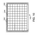
- the edge electrode setsurrounds only a portion of sensing electrodes perimeter.
- FIG. 10a fifth embodiment of a touch sensor device 1000 is illustrated.
- the touch sensor device 1000includes an edge electrode set 1002 partially surrounding sensing electrodes 1004 .
- the set of electrodes 1002consists of two edge electrodes that together surround a portion of the perimeter.
- This type of embodimentmaybe desirable in situations where it is desirable to expand effective area of the touch sensor in only certain directions. Thus, the effective area is expanded in areas where the edge electrodes are provided, but not expanded in other areas.
- a variety of different implementationscan be used.
- one edge electrode that surrounds at least 50% of the sensing electrode perimetercan be used.
- one or two edge electrodes that together surround at least 75% of the sensing electrodescan be used. In both cases the one or two edge electrodes can surround one or more sides of the sensing electrode perimeter, while not surrounding other portions of sensing electrode perimeter.
Landscapes
- Engineering & Computer Science (AREA)
- General Engineering & Computer Science (AREA)
- Theoretical Computer Science (AREA)
- Human Computer Interaction (AREA)
- Physics & Mathematics (AREA)
- General Physics & Mathematics (AREA)
- Position Input By Displaying (AREA)
Abstract
Description
Where there are i electrodes, xiand yiare the coordinates of each electrode, and siis the signal strength for each electrode.
Where there are j sensing electrodes (excluding edge electrodes) and k electrodes total (including both edge and sensing electrodes), r is the distance from the center of the pad to the center of each electrode, ω is the weighting factor of each electrode, and s is the signal strength of each electrode. The first two equations calculate preliminary object location coordinates Xcand Ycas a function of the signals measured in the sensing electrodes only. The third equation calculates the angular position θ as a function of the preliminary objection location coordinates. Thus, the angular position θ is calculated without the use of the edge electrodes. The fourth equation calculates a weighted radius Rkused to calculate the radial position. The fifth equation calculates the radial position R as a function of the weighted radius and the signals measured at all the electrodes, including the edge electrodes. Thus, the edge electrodes are used to provide radial information, extending the radius of the effective sensing area, but are not used to calculate angular information. Optimization can be performed by varying the rkused for each electrode as well as varying the weighting ωkassigned to each electrode to produce an optimal reported position versus actual finger position. It should be noted that while this example outputs position information in form of radial information R and angular position θ, this is just one example, and other systems can use different techniques.
In this example, the edge electrodes are again used in calculating the radial position R, but are not used in calculating the preliminary object location coordinates Xcand Yc. However, the effects of all electrodes, including both sensing and edge electrodes, are used to calculate the final object position X and Y.
Claims (23)
Priority Applications (2)
| Application Number | Priority Date | Filing Date | Title |
|---|---|---|---|
| US11/388,586US7656392B2 (en) | 2006-03-24 | 2006-03-24 | Touch sensor effective area enhancement |
| PCT/US2007/062933WO2007112172A1 (en) | 2006-03-24 | 2007-02-28 | Touch sensor effective area enhancement |
Applications Claiming Priority (1)
| Application Number | Priority Date | Filing Date | Title |
|---|---|---|---|
| US11/388,586US7656392B2 (en) | 2006-03-24 | 2006-03-24 | Touch sensor effective area enhancement |
Publications (2)
| Publication Number | Publication Date |
|---|---|
| US20070222766A1 US20070222766A1 (en) | 2007-09-27 |
| US7656392B2true US7656392B2 (en) | 2010-02-02 |
Family
ID=38198655
Family Applications (1)
| Application Number | Title | Priority Date | Filing Date |
|---|---|---|---|
| US11/388,586Active2028-12-03US7656392B2 (en) | 2006-03-24 | 2006-03-24 | Touch sensor effective area enhancement |
Country Status (2)
| Country | Link |
|---|---|
| US (1) | US7656392B2 (en) |
| WO (1) | WO2007112172A1 (en) |
Cited By (65)
| Publication number | Priority date | Publication date | Assignee | Title |
|---|---|---|---|---|
| US20080223705A1 (en)* | 2007-03-16 | 2008-09-18 | Inventec Appliances Corp. | Touch-sensing device and sensing method for electrical apparatus |
| US20080297174A1 (en)* | 2007-05-31 | 2008-12-04 | Sarangan Narasimhan | Capacitive sensing devices |
| US20090084611A1 (en)* | 2007-09-28 | 2009-04-02 | Au Optronics Corporation | Touch sensor layout design |
| US20100289759A1 (en)* | 2009-05-15 | 2010-11-18 | Apple Inc. | Input device with optimized capacitive sensing |
| US8040321B2 (en) | 2006-07-10 | 2011-10-18 | Cypress Semiconductor Corporation | Touch-sensor with shared capacitive sensors |
| US8058937B2 (en) | 2007-01-30 | 2011-11-15 | Cypress Semiconductor Corporation | Setting a discharge rate and a charge rate of a relaxation oscillator circuit |
| US8059015B2 (en) | 2006-05-25 | 2011-11-15 | Cypress Semiconductor Corporation | Capacitance sensing matrix for keyboard architecture |
| WO2012088549A1 (en) | 2010-12-23 | 2012-06-28 | Frederick Johannes Bruwer | Compact capacitive track pad |
| US8258986B2 (en) | 2007-07-03 | 2012-09-04 | Cypress Semiconductor Corporation | Capacitive-matrix keyboard with multiple touch detection |
| US20130141356A1 (en)* | 2011-12-06 | 2013-06-06 | Shih Hua Technology Ltd. | Touch panel |
| US8498100B1 (en) | 2012-03-02 | 2013-07-30 | Microsoft Corporation | Flexible hinge and removable attachment |
| US8654030B1 (en) | 2012-10-16 | 2014-02-18 | Microsoft Corporation | Antenna placement |
| US8719603B2 (en) | 2012-03-02 | 2014-05-06 | Microsoft Corporation | Accessory device authentication |
| US8733423B1 (en) | 2012-10-17 | 2014-05-27 | Microsoft Corporation | Metal alloy injection molding protrusions |
| US8749529B2 (en) | 2012-03-01 | 2014-06-10 | Microsoft Corporation | Sensor-in-pixel display system with near infrared filter |
| US8786767B2 (en) | 2012-11-02 | 2014-07-22 | Microsoft Corporation | Rapid synchronized lighting and shuttering |
| US20140224635A1 (en)* | 2012-09-27 | 2014-08-14 | Tpk Touch Systems (Xiamen) Inc. | Touch device and manufacturing method thereof |
| US8873227B2 (en) | 2012-03-02 | 2014-10-28 | Microsoft Corporation | Flexible hinge support layer |
| US8902191B2 (en) | 2009-01-28 | 2014-12-02 | Synaptics Incorporated | Proximity sensing for capacitive touch sensors |
| US8947353B2 (en) | 2012-06-12 | 2015-02-03 | Microsoft Corporation | Photosensor array gesture detection |
| US8949477B2 (en) | 2012-05-14 | 2015-02-03 | Microsoft Technology Licensing, Llc | Accessory device architecture |
| US8952892B2 (en) | 2012-11-01 | 2015-02-10 | Microsoft Corporation | Input location correction tables for input panels |
| US8964379B2 (en) | 2012-08-20 | 2015-02-24 | Microsoft Corporation | Switchable magnetic lock |
| US9019615B2 (en) | 2012-06-12 | 2015-04-28 | Microsoft Technology Licensing, Llc | Wide field-of-view virtual image projector |
| US9027631B2 (en) | 2012-10-17 | 2015-05-12 | Microsoft Technology Licensing, Llc | Metal alloy injection molding overflows |
| US9052414B2 (en) | 2012-02-07 | 2015-06-09 | Microsoft Technology Licensing, Llc | Virtual image device |
| US9064654B2 (en) | 2012-03-02 | 2015-06-23 | Microsoft Technology Licensing, Llc | Method of manufacturing an input device |
| US9075566B2 (en) | 2012-03-02 | 2015-07-07 | Microsoft Technoogy Licensing, LLC | Flexible hinge spine |
| US9073123B2 (en) | 2012-06-13 | 2015-07-07 | Microsoft Technology Licensing, Llc | Housing vents |
| US9152173B2 (en) | 2012-10-09 | 2015-10-06 | Microsoft Technology Licensing, Llc | Transparent display device |
| US9176538B2 (en) | 2013-02-05 | 2015-11-03 | Microsoft Technology Licensing, Llc | Input device configurations |
| US9201185B2 (en) | 2011-02-04 | 2015-12-01 | Microsoft Technology Licensing, Llc | Directional backlighting for display panels |
| US9256089B2 (en) | 2012-06-15 | 2016-02-09 | Microsoft Technology Licensing, Llc | Object-detecting backlight unit |
| US9304549B2 (en) | 2013-03-28 | 2016-04-05 | Microsoft Technology Licensing, Llc | Hinge mechanism for rotatable component attachment |
| US9317072B2 (en) | 2014-01-28 | 2016-04-19 | Microsoft Technology Licensing, Llc | Hinge mechanism with preset positions |
| US9354748B2 (en) | 2012-02-13 | 2016-05-31 | Microsoft Technology Licensing, Llc | Optical stylus interaction |
| US9355345B2 (en) | 2012-07-23 | 2016-05-31 | Microsoft Technology Licensing, Llc | Transparent tags with encoded data |
| US9360893B2 (en) | 2012-03-02 | 2016-06-07 | Microsoft Technology Licensing, Llc | Input device writing surface |
| US9426905B2 (en) | 2012-03-02 | 2016-08-23 | Microsoft Technology Licensing, Llc | Connection device for computing devices |
| US9447620B2 (en) | 2014-09-30 | 2016-09-20 | Microsoft Technology Licensing, Llc | Hinge mechanism with multiple preset positions |
| US9448631B2 (en) | 2013-12-31 | 2016-09-20 | Microsoft Technology Licensing, Llc | Input device haptics and pressure sensing |
| US9459160B2 (en) | 2012-06-13 | 2016-10-04 | Microsoft Technology Licensing, Llc | Input device sensor configuration |
| US9513748B2 (en) | 2012-12-13 | 2016-12-06 | Microsoft Technology Licensing, Llc | Combined display panel circuit |
| US9552777B2 (en) | 2013-05-10 | 2017-01-24 | Microsoft Technology Licensing, Llc | Phase control backlight |
| US9638835B2 (en) | 2013-03-05 | 2017-05-02 | Microsoft Technology Licensing, Llc | Asymmetric aberration correcting lens |
| US9661770B2 (en) | 2012-10-17 | 2017-05-23 | Microsoft Technology Licensing, Llc | Graphic formation via material ablation |
| US9684382B2 (en) | 2012-06-13 | 2017-06-20 | Microsoft Technology Licensing, Llc | Input device configuration having capacitive and pressure sensors |
| US9752361B2 (en) | 2015-06-18 | 2017-09-05 | Microsoft Technology Licensing, Llc | Multistage hinge |
| US9759854B2 (en) | 2014-02-17 | 2017-09-12 | Microsoft Technology Licensing, Llc | Input device outer layer and backlighting |
| US9864415B2 (en) | 2015-06-30 | 2018-01-09 | Microsoft Technology Licensing, Llc | Multistage friction hinge |
| US9870066B2 (en) | 2012-03-02 | 2018-01-16 | Microsoft Technology Licensing, Llc | Method of manufacturing an input device |
| US10031556B2 (en) | 2012-06-08 | 2018-07-24 | Microsoft Technology Licensing, Llc | User experience adaptation |
| US10037057B2 (en) | 2016-09-22 | 2018-07-31 | Microsoft Technology Licensing, Llc | Friction hinge |
| US10061385B2 (en) | 2016-01-22 | 2018-08-28 | Microsoft Technology Licensing, Llc | Haptic feedback for a touch input device |
| US10078103B2 (en) | 2016-08-26 | 2018-09-18 | Microsoft Technology Licensing, Llc | Fringing field booster |
| US10120420B2 (en) | 2014-03-21 | 2018-11-06 | Microsoft Technology Licensing, Llc | Lockable display and techniques enabling use of lockable displays |
| US10156889B2 (en) | 2014-09-15 | 2018-12-18 | Microsoft Technology Licensing, Llc | Inductive peripheral retention device |
| US10222889B2 (en) | 2015-06-03 | 2019-03-05 | Microsoft Technology Licensing, Llc | Force inputs and cursor control |
| US10324733B2 (en) | 2014-07-30 | 2019-06-18 | Microsoft Technology Licensing, Llc | Shutdown notifications |
| US10344797B2 (en) | 2016-04-05 | 2019-07-09 | Microsoft Technology Licensing, Llc | Hinge with multiple preset positions |
| US10416799B2 (en) | 2015-06-03 | 2019-09-17 | Microsoft Technology Licensing, Llc | Force sensing and inadvertent input control of an input device |
| US10578499B2 (en) | 2013-02-17 | 2020-03-03 | Microsoft Technology Licensing, Llc | Piezo-actuated virtual buttons for touch surfaces |
| US10795501B1 (en) | 2019-04-03 | 2020-10-06 | Ite Tech. Inc. | Touch apparatus |
| USRE48963E1 (en) | 2012-03-02 | 2022-03-08 | Microsoft Technology Licensing, Llc | Connection device for computing devices |
| US12293052B2 (en) | 2023-03-16 | 2025-05-06 | Samsung Display Co., Ltd. | Electronic device |
Families Citing this family (46)
| Publication number | Priority date | Publication date | Assignee | Title |
|---|---|---|---|---|
| US20070229470A1 (en)* | 2006-03-31 | 2007-10-04 | Warren Snyder | Capacitive touch sense device having polygonal shaped sensor elements |
| US8717302B1 (en)* | 2006-06-30 | 2014-05-06 | Cypress Semiconductor Corporation | Apparatus and method for recognizing a gesture on a sensing device |
| US20080088595A1 (en)* | 2006-10-12 | 2008-04-17 | Hua Liu | Interconnected two-substrate layer touchpad capacitive sensing device |
| KR100837738B1 (en)* | 2006-10-16 | 2008-06-13 | 주식회사 애트랩 | Electronic device and touch panel placement method |
| JP4475321B2 (en)* | 2007-11-26 | 2010-06-09 | ソニー株式会社 | Display device |
| EP2079008A1 (en) | 2007-12-26 | 2009-07-15 | TPO Displays Corp. | Position sensing display |
| KR101080183B1 (en)* | 2008-04-04 | 2011-11-07 | (주)멜파스 | Touch sensing apparatus having improved location detection performance for periphery touch |
| US20090327974A1 (en)* | 2008-06-26 | 2009-12-31 | Microsoft Corporation | User interface for gestural control |
| US8228306B2 (en) | 2008-07-23 | 2012-07-24 | Flextronics Ap, Llc | Integration design for capacitive touch panels and liquid crystal displays |
| US9128568B2 (en) | 2008-07-30 | 2015-09-08 | New Vision Display (Shenzhen) Co., Limited | Capacitive touch panel with FPC connector electrically coupled to conductive traces of face-to-face ITO pattern structure in single plane |
| US8209861B2 (en) | 2008-12-05 | 2012-07-03 | Flextronics Ap, Llc | Method for manufacturing a touch screen sensor assembly |
| US8411045B2 (en)* | 2008-12-15 | 2013-04-02 | Sony Corporation | Touch sensitive displays with coplanar capacitive touch and proximity sensor pads and related touch panels |
| US8274486B2 (en) | 2008-12-22 | 2012-09-25 | Flextronics Ap, Llc | Diamond pattern on a single layer |
| TWI373665B (en)* | 2008-12-25 | 2012-10-01 | Au Optronics Corp | Touch panel structure |
| JP5366051B2 (en)* | 2009-04-20 | 2013-12-11 | 株式会社ジャパンディスプレイ | Information input device, display device |
| US8154529B2 (en)* | 2009-05-14 | 2012-04-10 | Atmel Corporation | Two-dimensional touch sensors |
| US20110057669A1 (en)* | 2009-09-08 | 2011-03-10 | Amlogic Co., Ltd. | Capacitive Sensor |
| US9383867B2 (en)* | 2009-11-09 | 2016-07-05 | Rohm Co., Ltd. | Touch display having proximity sensor electrode pair with each electrode formed on the top face of the display panel so as to overlap the display region |
| US8558802B2 (en)* | 2009-11-21 | 2013-10-15 | Freescale Semiconductor, Inc. | Methods and apparatus for performing capacitive touch sensing and proximity detection |
| TWI408441B (en)* | 2009-12-09 | 2013-09-11 | Au Optronics Corp | Touch display panel and touch substrate |
| KR101040851B1 (en)* | 2010-03-23 | 2011-06-14 | 삼성모바일디스플레이주식회사 | Touch screen panel |
| US9285929B2 (en) | 2010-03-30 | 2016-03-15 | New Vision Display (Shenzhen) Co., Limited | Touchscreen system with simplified mechanical touchscreen design using capacitance and acoustic sensing technologies, and method therefor |
| WO2012052069A1 (en)* | 2010-10-22 | 2012-04-26 | Sony Ericsson Mobile Communications Ab | Mobile communication device with three-dimensional sensing and a method therefore |
| WO2012083553A1 (en)* | 2010-12-24 | 2012-06-28 | 江苏惠通集团有限责任公司 | Press key detection board |
| TW201237717A (en)* | 2011-03-04 | 2012-09-16 | Raydium Semiconductor Corp | Touch panel and touch pad |
| JP2012221120A (en)* | 2011-04-06 | 2012-11-12 | Fujitsu Component Ltd | Touch panel |
| US8674956B2 (en)* | 2011-06-13 | 2014-03-18 | Chimei Innolux Corporation | In-cell touch sensor touch area enhancing algorithm |
| US8988086B1 (en) | 2011-08-10 | 2015-03-24 | Cypress Semiconductor Corporation | Capacitive sensor array with pattern variation |
| US9134858B2 (en)* | 2011-11-03 | 2015-09-15 | Innolux Corporation | Touch panel for electrostatic discharge protection and electronic device using the same |
| US8525955B2 (en) | 2012-01-31 | 2013-09-03 | Multek Display (Hong Kong) Limited | Heater for liquid crystal display |
| US9600125B2 (en) | 2012-07-18 | 2017-03-21 | Ctpress Semiconductor Corporation | Sensor array with edge pattern |
| JP6063201B2 (en)* | 2012-10-15 | 2017-01-18 | 株式会社ソニー・インタラクティブエンタテインメント | Operation device |
| TWM448018U (en)* | 2012-10-31 | 2013-03-01 | Nuvoton Technology Corp | Touch sensing panel |
| US9594462B2 (en) | 2013-04-22 | 2017-03-14 | Cypress Semiconductor Corporation | Uniform signals from non-uniform patterns of electrodes |
| TW201445406A (en)* | 2013-05-24 | 2014-12-01 | Wintek Corp | Touch panel |
| WO2015038133A1 (en)* | 2013-09-12 | 2015-03-19 | Intel Corporation | Detecting gestures on the side of a computing device |
| TWI486843B (en)* | 2013-09-13 | 2015-06-01 | Henghao Technology Co Ltd | Touch panel |
| KR102598155B1 (en)* | 2016-10-27 | 2023-11-07 | 삼성디스플레이 주식회사 | Electronic device |
| US10754465B2 (en)* | 2017-02-15 | 2020-08-25 | Sharp Kabushiki Kaisha | Display device |
| KR101818548B1 (en) | 2017-03-21 | 2018-01-16 | 엘지디스플레이 주식회사 | Display device with integrated touch screen and touch integrated circuit |
| CN107239174A (en)* | 2017-07-19 | 2017-10-10 | 南昌欧菲光科技有限公司 | Display module and its pressure sensor module |
| CN107390963B (en) | 2017-08-17 | 2019-08-30 | 京东方科技集团股份有限公司 | Touch substrate and display device |
| CN108052216B (en)* | 2018-01-02 | 2020-12-01 | 京东方科技集团股份有限公司 | Active pen, active pen touch system and active pen touch method |
| JP7280032B2 (en)* | 2018-11-27 | 2023-05-23 | ローム株式会社 | input devices, automobiles |
| CN115291744A (en)* | 2021-05-03 | 2022-11-04 | 联咏科技股份有限公司 | Touch device |
| US11960693B1 (en) | 2023-05-23 | 2024-04-16 | Rockwell Collins, Inc. | Resistive touch sensor with improved force uniformity |
Citations (26)
| Publication number | Priority date | Publication date | Assignee | Title |
|---|---|---|---|---|
| US4550221A (en) | 1983-10-07 | 1985-10-29 | Scott Mabusth | Touch sensitive control device |
| US5159159A (en) | 1990-12-07 | 1992-10-27 | Asher David J | Touch sensor and controller |
| US5543589A (en) | 1994-05-23 | 1996-08-06 | International Business Machines Corporation | Touchpad with dual sensor that simplifies scanning |
| US6163313A (en)* | 1997-12-12 | 2000-12-19 | Aroyan; James L. | Touch sensitive screen and method |
| US6188391B1 (en) | 1998-07-09 | 2001-02-13 | Synaptics, Inc. | Two-layer capacitive touchpad and method of making same |
| US6225678B1 (en) | 1998-12-23 | 2001-05-01 | Microchip Technology Incorporated | Layout technique for a matching capacitor array using a continuous top electrode |
| US6392636B1 (en) | 1998-01-22 | 2002-05-21 | Stmicroelectronics, Inc. | Touchpad providing screen cursor/pointer movement control |
| US6414671B1 (en)* | 1992-06-08 | 2002-07-02 | Synaptics Incorporated | Object position detector with edge motion feature and gesture recognition |
| US20030067451A1 (en) | 1994-11-14 | 2003-04-10 | James Peter Tagg | Capacitive touch detectors |
| US20030085882A1 (en) | 2001-11-08 | 2003-05-08 | Koninklijke Philips Electronics N.V. | Multi-point touch pad |
| US20030161512A1 (en) | 2000-06-09 | 2003-08-28 | Svein Mathiassen | Sensor unit, especially for fingerprint sensors |
| US20030184527A1 (en) | 2002-03-27 | 2003-10-02 | Inotouch Technology Co., Ltd. | Touch panel structure for increasing active area |
| US20040055396A1 (en) | 2002-09-24 | 2004-03-25 | Hideo Morimoto | Sensor sheet |
| JP2004145761A (en) | 2002-10-25 | 2004-05-20 | Kawaguchiko Seimitsu Co Ltd | Touch panel |
| US6841225B2 (en)* | 1999-07-30 | 2005-01-11 | 3M Innovative Properties, Company | Touch screen with an applied edge electrode pattern |
| US20050089200A1 (en) | 2002-03-01 | 2005-04-28 | Idex Asa | Sensor module for measuring surfaces |
| JP2005128819A (en) | 2003-10-24 | 2005-05-19 | Kawaguchiko Seimitsu Co Ltd | Touch panel and screen input type display device equipped therewith |
| JP2005149967A (en) | 2003-11-18 | 2005-06-09 | Kawaguchiko Seimitsu Co Ltd | Touch panel and screen input type display device with the same |
| US20050270273A1 (en) | 2003-06-13 | 2005-12-08 | Victor Marten | Sensor for capacitive touch pad pointing device |
| US7046230B2 (en)* | 2001-10-22 | 2006-05-16 | Apple Computer, Inc. | Touch pad handheld device |
| US20060203403A1 (en) | 2005-03-08 | 2006-09-14 | Schediwy Richard R | Strike ring based electrostatic discharge protection |
| US7129935B2 (en) | 2003-06-02 | 2006-10-31 | Synaptics Incorporated | Sensor patterns for a capacitive sensing apparatus |
| US7202859B1 (en) | 2002-08-09 | 2007-04-10 | Synaptics, Inc. | Capacitive sensing pattern |
| US7218124B1 (en) | 2006-01-30 | 2007-05-15 | Synaptics Incorporated | Capacitive sensing apparatus designs |
| US7307624B2 (en)* | 2003-12-30 | 2007-12-11 | 3M Innovative Properties Company | Touch sensor with linearized response |
| US7327352B2 (en)* | 2002-06-14 | 2008-02-05 | 3M Innovative Properties Company | Linearized conductive surface |
- 2006
- 2006-03-24USUS11/388,586patent/US7656392B2/enactiveActive
- 2007
- 2007-02-28WOPCT/US2007/062933patent/WO2007112172A1/enactiveApplication Filing
Patent Citations (26)
| Publication number | Priority date | Publication date | Assignee | Title |
|---|---|---|---|---|
| US4550221A (en) | 1983-10-07 | 1985-10-29 | Scott Mabusth | Touch sensitive control device |
| US5159159A (en) | 1990-12-07 | 1992-10-27 | Asher David J | Touch sensor and controller |
| US6414671B1 (en)* | 1992-06-08 | 2002-07-02 | Synaptics Incorporated | Object position detector with edge motion feature and gesture recognition |
| US5543589A (en) | 1994-05-23 | 1996-08-06 | International Business Machines Corporation | Touchpad with dual sensor that simplifies scanning |
| US20030067451A1 (en) | 1994-11-14 | 2003-04-10 | James Peter Tagg | Capacitive touch detectors |
| US6163313A (en)* | 1997-12-12 | 2000-12-19 | Aroyan; James L. | Touch sensitive screen and method |
| US6392636B1 (en) | 1998-01-22 | 2002-05-21 | Stmicroelectronics, Inc. | Touchpad providing screen cursor/pointer movement control |
| US6188391B1 (en) | 1998-07-09 | 2001-02-13 | Synaptics, Inc. | Two-layer capacitive touchpad and method of making same |
| US6225678B1 (en) | 1998-12-23 | 2001-05-01 | Microchip Technology Incorporated | Layout technique for a matching capacitor array using a continuous top electrode |
| US6841225B2 (en)* | 1999-07-30 | 2005-01-11 | 3M Innovative Properties, Company | Touch screen with an applied edge electrode pattern |
| US20030161512A1 (en) | 2000-06-09 | 2003-08-28 | Svein Mathiassen | Sensor unit, especially for fingerprint sensors |
| US7046230B2 (en)* | 2001-10-22 | 2006-05-16 | Apple Computer, Inc. | Touch pad handheld device |
| US20030085882A1 (en) | 2001-11-08 | 2003-05-08 | Koninklijke Philips Electronics N.V. | Multi-point touch pad |
| US20050089200A1 (en) | 2002-03-01 | 2005-04-28 | Idex Asa | Sensor module for measuring surfaces |
| US20030184527A1 (en) | 2002-03-27 | 2003-10-02 | Inotouch Technology Co., Ltd. | Touch panel structure for increasing active area |
| US7327352B2 (en)* | 2002-06-14 | 2008-02-05 | 3M Innovative Properties Company | Linearized conductive surface |
| US7202859B1 (en) | 2002-08-09 | 2007-04-10 | Synaptics, Inc. | Capacitive sensing pattern |
| US20040055396A1 (en) | 2002-09-24 | 2004-03-25 | Hideo Morimoto | Sensor sheet |
| JP2004145761A (en) | 2002-10-25 | 2004-05-20 | Kawaguchiko Seimitsu Co Ltd | Touch panel |
| US7129935B2 (en) | 2003-06-02 | 2006-10-31 | Synaptics Incorporated | Sensor patterns for a capacitive sensing apparatus |
| US20050270273A1 (en) | 2003-06-13 | 2005-12-08 | Victor Marten | Sensor for capacitive touch pad pointing device |
| JP2005128819A (en) | 2003-10-24 | 2005-05-19 | Kawaguchiko Seimitsu Co Ltd | Touch panel and screen input type display device equipped therewith |
| JP2005149967A (en) | 2003-11-18 | 2005-06-09 | Kawaguchiko Seimitsu Co Ltd | Touch panel and screen input type display device with the same |
| US7307624B2 (en)* | 2003-12-30 | 2007-12-11 | 3M Innovative Properties Company | Touch sensor with linearized response |
| US20060203403A1 (en) | 2005-03-08 | 2006-09-14 | Schediwy Richard R | Strike ring based electrostatic discharge protection |
| US7218124B1 (en) | 2006-01-30 | 2007-05-15 | Synaptics Incorporated | Capacitive sensing apparatus designs |
Non-Patent Citations (1)
| Title |
|---|
| International Search Report for PCT/US2007/062933, mailed Jul. 16, 2007. |
Cited By (132)
| Publication number | Priority date | Publication date | Assignee | Title |
|---|---|---|---|---|
| US8482437B1 (en) | 2006-05-25 | 2013-07-09 | Cypress Semiconductor Corporation | Capacitance sensing matrix for keyboard architecture |
| US8059015B2 (en) | 2006-05-25 | 2011-11-15 | Cypress Semiconductor Corporation | Capacitance sensing matrix for keyboard architecture |
| US9019133B1 (en) | 2006-05-25 | 2015-04-28 | Cypress Semiconductor Corporation | Low pin count solution using capacitance sensing matrix for keyboard architecture |
| US8040321B2 (en) | 2006-07-10 | 2011-10-18 | Cypress Semiconductor Corporation | Touch-sensor with shared capacitive sensors |
| US8058937B2 (en) | 2007-01-30 | 2011-11-15 | Cypress Semiconductor Corporation | Setting a discharge rate and a charge rate of a relaxation oscillator circuit |
| US20080223705A1 (en)* | 2007-03-16 | 2008-09-18 | Inventec Appliances Corp. | Touch-sensing device and sensing method for electrical apparatus |
| US20080297174A1 (en)* | 2007-05-31 | 2008-12-04 | Sarangan Narasimhan | Capacitive sensing devices |
| US8258986B2 (en) | 2007-07-03 | 2012-09-04 | Cypress Semiconductor Corporation | Capacitive-matrix keyboard with multiple touch detection |
| US20090084611A1 (en)* | 2007-09-28 | 2009-04-02 | Au Optronics Corporation | Touch sensor layout design |
| US7834862B2 (en)* | 2007-09-28 | 2010-11-16 | Au Optronics Corporation | Touch sensor layout design |
| US8902191B2 (en) | 2009-01-28 | 2014-12-02 | Synaptics Incorporated | Proximity sensing for capacitive touch sensors |
| US9354751B2 (en)* | 2009-05-15 | 2016-05-31 | Apple Inc. | Input device with optimized capacitive sensing |
| US20100289759A1 (en)* | 2009-05-15 | 2010-11-18 | Apple Inc. | Input device with optimized capacitive sensing |
| WO2012088549A1 (en) | 2010-12-23 | 2012-06-28 | Frederick Johannes Bruwer | Compact capacitive track pad |
| US9201185B2 (en) | 2011-02-04 | 2015-12-01 | Microsoft Technology Licensing, Llc | Directional backlighting for display panels |
| US20130141356A1 (en)* | 2011-12-06 | 2013-06-06 | Shih Hua Technology Ltd. | Touch panel |
| US9052414B2 (en) | 2012-02-07 | 2015-06-09 | Microsoft Technology Licensing, Llc | Virtual image device |
| US9354748B2 (en) | 2012-02-13 | 2016-05-31 | Microsoft Technology Licensing, Llc | Optical stylus interaction |
| US8749529B2 (en) | 2012-03-01 | 2014-06-10 | Microsoft Corporation | Sensor-in-pixel display system with near infrared filter |
| US9176900B2 (en) | 2012-03-02 | 2015-11-03 | Microsoft Technology Licensing, Llc | Flexible hinge and removable attachment |
| US9047207B2 (en) | 2012-03-02 | 2015-06-02 | Microsoft Technology Licensing, Llc | Mobile device power state |
| US8699215B2 (en) | 2012-03-02 | 2014-04-15 | Microsoft Corporation | Flexible hinge spine |
| US8719603B2 (en) | 2012-03-02 | 2014-05-06 | Microsoft Corporation | Accessory device authentication |
| US8724302B2 (en) | 2012-03-02 | 2014-05-13 | Microsoft Corporation | Flexible hinge support layer |
| USRE48963E1 (en) | 2012-03-02 | 2022-03-08 | Microsoft Technology Licensing, Llc | Connection device for computing devices |
| US8646999B2 (en) | 2012-03-02 | 2014-02-11 | Microsoft Corporation | Pressure sensitive key normalization |
| US8780540B2 (en) | 2012-03-02 | 2014-07-15 | Microsoft Corporation | Flexible hinge and removable attachment |
| US8780541B2 (en) | 2012-03-02 | 2014-07-15 | Microsoft Corporation | Flexible hinge and removable attachment |
| US10963087B2 (en) | 2012-03-02 | 2021-03-30 | Microsoft Technology Licensing, Llc | Pressure sensitive keys |
| US8791382B2 (en) | 2012-03-02 | 2014-07-29 | Microsoft Corporation | Input device securing techniques |
| US10013030B2 (en) | 2012-03-02 | 2018-07-03 | Microsoft Technology Licensing, Llc | Multiple position input device cover |
| US8830668B2 (en) | 2012-03-02 | 2014-09-09 | Microsoft Corporation | Flexible hinge and removable attachment |
| US8850241B2 (en) | 2012-03-02 | 2014-09-30 | Microsoft Corporation | Multi-stage power adapter configured to provide low power upon initial connection of the power adapter to the host device and high power thereafter upon notification from the host device to the power adapter |
| US8854799B2 (en) | 2012-03-02 | 2014-10-07 | Microsoft Corporation | Flux fountain |
| US8873227B2 (en) | 2012-03-02 | 2014-10-28 | Microsoft Corporation | Flexible hinge support layer |
| US8896993B2 (en) | 2012-03-02 | 2014-11-25 | Microsoft Corporation | Input device layers and nesting |
| US8903517B2 (en) | 2012-03-02 | 2014-12-02 | Microsoft Corporation | Computer device and an apparatus having sensors configured for measuring spatial information indicative of a position of the computing devices |
| US8614666B2 (en) | 2012-03-02 | 2013-12-24 | Microsoft Corporation | Sensing user input at display area edge |
| US8935774B2 (en) | 2012-03-02 | 2015-01-13 | Microsoft Corporation | Accessory device authentication |
| US9946307B2 (en) | 2012-03-02 | 2018-04-17 | Microsoft Technology Licensing, Llc | Classifying the intent of user input |
| US8947864B2 (en) | 2012-03-02 | 2015-02-03 | Microsoft Corporation | Flexible hinge and removable attachment |
| US9904327B2 (en) | 2012-03-02 | 2018-02-27 | Microsoft Technology Licensing, Llc | Flexible hinge and removable attachment |
| US9870066B2 (en) | 2012-03-02 | 2018-01-16 | Microsoft Technology Licensing, Llc | Method of manufacturing an input device |
| US9852855B2 (en) | 2012-03-02 | 2017-12-26 | Microsoft Technology Licensing, Llc | Pressure sensitive key normalization |
| US9793073B2 (en) | 2012-03-02 | 2017-10-17 | Microsoft Technology Licensing, Llc | Backlighting a fabric enclosure of a flexible cover |
| US8610015B2 (en) | 2012-03-02 | 2013-12-17 | Microsoft Corporation | Input device securing techniques |
| US9766663B2 (en) | 2012-03-02 | 2017-09-19 | Microsoft Technology Licensing, Llc | Hinge for component attachment |
| US9710093B2 (en) | 2012-03-02 | 2017-07-18 | Microsoft Technology Licensing, Llc | Pressure sensitive key normalization |
| US8543227B1 (en) | 2012-03-02 | 2013-09-24 | Microsoft Corporation | Sensor fusion algorithm |
| US8570725B2 (en) | 2012-03-02 | 2013-10-29 | Microsoft Corporation | Flexible hinge and removable attachment |
| US9064654B2 (en) | 2012-03-02 | 2015-06-23 | Microsoft Technology Licensing, Llc | Method of manufacturing an input device |
| US9075566B2 (en) | 2012-03-02 | 2015-07-07 | Microsoft Technoogy Licensing, LLC | Flexible hinge spine |
| US9678542B2 (en) | 2012-03-02 | 2017-06-13 | Microsoft Technology Licensing, Llc | Multiple position input device cover |
| US9098117B2 (en) | 2012-03-02 | 2015-08-04 | Microsoft Technology Licensing, Llc | Classifying the intent of user input |
| US9619071B2 (en) | 2012-03-02 | 2017-04-11 | Microsoft Technology Licensing, Llc | Computing device and an apparatus having sensors configured for measuring spatial information indicative of a position of the computing devices |
| US9111703B2 (en) | 2012-03-02 | 2015-08-18 | Microsoft Technology Licensing, Llc | Sensor stack venting |
| US9116550B2 (en) | 2012-03-02 | 2015-08-25 | Microsoft Technology Licensing, Llc | Device kickstand |
| US9134808B2 (en) | 2012-03-02 | 2015-09-15 | Microsoft Technology Licensing, Llc | Device kickstand |
| US9134807B2 (en) | 2012-03-02 | 2015-09-15 | Microsoft Technology Licensing, Llc | Pressure sensitive key normalization |
| US9146620B2 (en) | 2012-03-02 | 2015-09-29 | Microsoft Technology Licensing, Llc | Input device assembly |
| US9618977B2 (en) | 2012-03-02 | 2017-04-11 | Microsoft Technology Licensing, Llc | Input device securing techniques |
| US9465412B2 (en) | 2012-03-02 | 2016-10-11 | Microsoft Technology Licensing, Llc | Input device layers and nesting |
| US9158383B2 (en) | 2012-03-02 | 2015-10-13 | Microsoft Technology Licensing, Llc | Force concentrator |
| US9158384B2 (en) | 2012-03-02 | 2015-10-13 | Microsoft Technology Licensing, Llc | Flexible hinge protrusion attachment |
| US9176901B2 (en) | 2012-03-02 | 2015-11-03 | Microsoft Technology Licensing, Llc | Flux fountain |
| US9460029B2 (en) | 2012-03-02 | 2016-10-04 | Microsoft Technology Licensing, Llc | Pressure sensitive keys |
| US8564944B2 (en) | 2012-03-02 | 2013-10-22 | Microsoft Corporation | Flux fountain |
| US8548608B2 (en) | 2012-03-02 | 2013-10-01 | Microsoft Corporation | Sensor fusion algorithm |
| US9426905B2 (en) | 2012-03-02 | 2016-08-23 | Microsoft Technology Licensing, Llc | Connection device for computing devices |
| US9268373B2 (en) | 2012-03-02 | 2016-02-23 | Microsoft Technology Licensing, Llc | Flexible hinge spine |
| US9275809B2 (en) | 2012-03-02 | 2016-03-01 | Microsoft Technology Licensing, Llc | Device camera angle |
| US9298236B2 (en) | 2012-03-02 | 2016-03-29 | Microsoft Technology Licensing, Llc | Multi-stage power adapter configured to provide a first power level upon initial connection of the power adapter to the host device and a second power level thereafter upon notification from the host device to the power adapter |
| US9411751B2 (en) | 2012-03-02 | 2016-08-09 | Microsoft Technology Licensing, Llc | Key formation |
| US9304948B2 (en) | 2012-03-02 | 2016-04-05 | Microsoft Technology Licensing, Llc | Sensing user input at display area edge |
| US9304949B2 (en) | 2012-03-02 | 2016-04-05 | Microsoft Technology Licensing, Llc | Sensing user input at display area edge |
| US9360893B2 (en) | 2012-03-02 | 2016-06-07 | Microsoft Technology Licensing, Llc | Input device writing surface |
| US8498100B1 (en) | 2012-03-02 | 2013-07-30 | Microsoft Corporation | Flexible hinge and removable attachment |
| US9348605B2 (en) | 2012-05-14 | 2016-05-24 | Microsoft Technology Licensing, Llc | System and method for accessory device architecture that passes human interface device (HID) data via intermediate processor |
| US8949477B2 (en) | 2012-05-14 | 2015-02-03 | Microsoft Technology Licensing, Llc | Accessory device architecture |
| US9098304B2 (en) | 2012-05-14 | 2015-08-04 | Microsoft Technology Licensing, Llc | Device enumeration support method for computing devices that does not natively support device enumeration |
| US9959241B2 (en) | 2012-05-14 | 2018-05-01 | Microsoft Technology Licensing, Llc | System and method for accessory device architecture that passes via intermediate processor a descriptor when processing in a low power state |
| US10031556B2 (en) | 2012-06-08 | 2018-07-24 | Microsoft Technology Licensing, Llc | User experience adaptation |
| US9019615B2 (en) | 2012-06-12 | 2015-04-28 | Microsoft Technology Licensing, Llc | Wide field-of-view virtual image projector |
| US8947353B2 (en) | 2012-06-12 | 2015-02-03 | Microsoft Corporation | Photosensor array gesture detection |
| US10107994B2 (en) | 2012-06-12 | 2018-10-23 | Microsoft Technology Licensing, Llc | Wide field-of-view virtual image projector |
| US9073123B2 (en) | 2012-06-13 | 2015-07-07 | Microsoft Technology Licensing, Llc | Housing vents |
| US9952106B2 (en) | 2012-06-13 | 2018-04-24 | Microsoft Technology Licensing, Llc | Input device sensor configuration |
| US9684382B2 (en) | 2012-06-13 | 2017-06-20 | Microsoft Technology Licensing, Llc | Input device configuration having capacitive and pressure sensors |
| US10228770B2 (en) | 2012-06-13 | 2019-03-12 | Microsoft Technology Licensing, Llc | Input device configuration having capacitive and pressure sensors |
| US9459160B2 (en) | 2012-06-13 | 2016-10-04 | Microsoft Technology Licensing, Llc | Input device sensor configuration |
| US9256089B2 (en) | 2012-06-15 | 2016-02-09 | Microsoft Technology Licensing, Llc | Object-detecting backlight unit |
| US9355345B2 (en) | 2012-07-23 | 2016-05-31 | Microsoft Technology Licensing, Llc | Transparent tags with encoded data |
| US8964379B2 (en) | 2012-08-20 | 2015-02-24 | Microsoft Corporation | Switchable magnetic lock |
| US9824808B2 (en) | 2012-08-20 | 2017-11-21 | Microsoft Technology Licensing, Llc | Switchable magnetic lock |
| US9148143B2 (en)* | 2012-09-27 | 2015-09-29 | Tpk Touch Systems (Xiamen) Inc. | Touch device and manufacturing method thereof |
| US20140224635A1 (en)* | 2012-09-27 | 2014-08-14 | Tpk Touch Systems (Xiamen) Inc. | Touch device and manufacturing method thereof |
| US9152173B2 (en) | 2012-10-09 | 2015-10-06 | Microsoft Technology Licensing, Llc | Transparent display device |
| US9432070B2 (en) | 2012-10-16 | 2016-08-30 | Microsoft Technology Licensing, Llc | Antenna placement |
| US8654030B1 (en) | 2012-10-16 | 2014-02-18 | Microsoft Corporation | Antenna placement |
| US9661770B2 (en) | 2012-10-17 | 2017-05-23 | Microsoft Technology Licensing, Llc | Graphic formation via material ablation |
| US9027631B2 (en) | 2012-10-17 | 2015-05-12 | Microsoft Technology Licensing, Llc | Metal alloy injection molding overflows |
| US8733423B1 (en) | 2012-10-17 | 2014-05-27 | Microsoft Corporation | Metal alloy injection molding protrusions |
| US8991473B2 (en) | 2012-10-17 | 2015-03-31 | Microsoft Technology Holding, LLC | Metal alloy injection molding protrusions |
| US8952892B2 (en) | 2012-11-01 | 2015-02-10 | Microsoft Corporation | Input location correction tables for input panels |
| US9544504B2 (en) | 2012-11-02 | 2017-01-10 | Microsoft Technology Licensing, Llc | Rapid synchronized lighting and shuttering |
| US8786767B2 (en) | 2012-11-02 | 2014-07-22 | Microsoft Corporation | Rapid synchronized lighting and shuttering |
| US9513748B2 (en) | 2012-12-13 | 2016-12-06 | Microsoft Technology Licensing, Llc | Combined display panel circuit |
| US9176538B2 (en) | 2013-02-05 | 2015-11-03 | Microsoft Technology Licensing, Llc | Input device configurations |
| US10578499B2 (en) | 2013-02-17 | 2020-03-03 | Microsoft Technology Licensing, Llc | Piezo-actuated virtual buttons for touch surfaces |
| US9638835B2 (en) | 2013-03-05 | 2017-05-02 | Microsoft Technology Licensing, Llc | Asymmetric aberration correcting lens |
| US9304549B2 (en) | 2013-03-28 | 2016-04-05 | Microsoft Technology Licensing, Llc | Hinge mechanism for rotatable component attachment |
| US9552777B2 (en) | 2013-05-10 | 2017-01-24 | Microsoft Technology Licensing, Llc | Phase control backlight |
| US9448631B2 (en) | 2013-12-31 | 2016-09-20 | Microsoft Technology Licensing, Llc | Input device haptics and pressure sensing |
| US10359848B2 (en) | 2013-12-31 | 2019-07-23 | Microsoft Technology Licensing, Llc | Input device haptics and pressure sensing |
| US9317072B2 (en) | 2014-01-28 | 2016-04-19 | Microsoft Technology Licensing, Llc | Hinge mechanism with preset positions |
| US9759854B2 (en) | 2014-02-17 | 2017-09-12 | Microsoft Technology Licensing, Llc | Input device outer layer and backlighting |
| US10120420B2 (en) | 2014-03-21 | 2018-11-06 | Microsoft Technology Licensing, Llc | Lockable display and techniques enabling use of lockable displays |
| US10324733B2 (en) | 2014-07-30 | 2019-06-18 | Microsoft Technology Licensing, Llc | Shutdown notifications |
| US10156889B2 (en) | 2014-09-15 | 2018-12-18 | Microsoft Technology Licensing, Llc | Inductive peripheral retention device |
| US9447620B2 (en) | 2014-09-30 | 2016-09-20 | Microsoft Technology Licensing, Llc | Hinge mechanism with multiple preset positions |
| US9964998B2 (en) | 2014-09-30 | 2018-05-08 | Microsoft Technology Licensing, Llc | Hinge mechanism with multiple preset positions |
| US10222889B2 (en) | 2015-06-03 | 2019-03-05 | Microsoft Technology Licensing, Llc | Force inputs and cursor control |
| US10416799B2 (en) | 2015-06-03 | 2019-09-17 | Microsoft Technology Licensing, Llc | Force sensing and inadvertent input control of an input device |
| US9752361B2 (en) | 2015-06-18 | 2017-09-05 | Microsoft Technology Licensing, Llc | Multistage hinge |
| US9864415B2 (en) | 2015-06-30 | 2018-01-09 | Microsoft Technology Licensing, Llc | Multistage friction hinge |
| US10606322B2 (en) | 2015-06-30 | 2020-03-31 | Microsoft Technology Licensing, Llc | Multistage friction hinge |
| US10061385B2 (en) | 2016-01-22 | 2018-08-28 | Microsoft Technology Licensing, Llc | Haptic feedback for a touch input device |
| US10344797B2 (en) | 2016-04-05 | 2019-07-09 | Microsoft Technology Licensing, Llc | Hinge with multiple preset positions |
| US10078103B2 (en) | 2016-08-26 | 2018-09-18 | Microsoft Technology Licensing, Llc | Fringing field booster |
| US10037057B2 (en) | 2016-09-22 | 2018-07-31 | Microsoft Technology Licensing, Llc | Friction hinge |
| US10795501B1 (en) | 2019-04-03 | 2020-10-06 | Ite Tech. Inc. | Touch apparatus |
| US12293052B2 (en) | 2023-03-16 | 2025-05-06 | Samsung Display Co., Ltd. | Electronic device |
Also Published As
| Publication number | Publication date |
|---|---|
| WO2007112172A1 (en) | 2007-10-04 |
| US20070222766A1 (en) | 2007-09-27 |
Similar Documents
| Publication | Publication Date | Title |
|---|---|---|
| US7656392B2 (en) | Touch sensor effective area enhancement | |
| US10254860B2 (en) | Touch pad with flexible substrate | |
| US20090040191A1 (en) | Capacitive touch sensor with conductive trace lines in bonding region | |
| CN105556443B (en) | Method and apparatus for click detection of pressure sensitive panel using dynamic threshold | |
| US9459734B2 (en) | Input device with deflectable electrode | |
| US8674950B2 (en) | Dual-sensing-mode touch-sensor device | |
| CN106170750B (en) | Water repellency on capacitive sensors | |
| CN102150109B (en) | Capacitive touch panel device of high-sensitivity digital system | |
| US9772729B2 (en) | Input device with capacitive force sensor and method for constructing the same | |
| US20130088448A1 (en) | Touch screen panel | |
| US8773386B2 (en) | Methods and apparatus to scan a targeted portion of an input device to detect a presence | |
| US20090289902A1 (en) | Proximity sensor device and method with subregion based swipethrough data entry | |
| US20110278078A1 (en) | Input device with force sensing | |
| US8743061B2 (en) | Touch sensing method and electronic device | |
| JP2012529126A (en) | Input device and method with pressure sensitive layer | |
| EP2513756A2 (en) | System and method for measuring individual force in multi-object sensing | |
| US20090288889A1 (en) | Proximity sensor device and method with swipethrough data entry | |
| CN105683886A (en) | Method and apparatus for computing coordinates with high noise immunity in touch applications | |
| US20160034071A1 (en) | Capacitive type touch panel | |
| US20110148436A1 (en) | System and method for determining a number of objects in a capacitive sensing region using signal grouping | |
| US8600688B2 (en) | Geometrically based button discrimination in capacitive sensing applications | |
| US20110148438A1 (en) | System and method for determining a number of objects in a capacitive sensing region using a shape factor | |
| KR101093615B1 (en) | 3D Sensing Panel | |
| US20170060333A1 (en) | Capacitive type touch panel | |
| CN105278780A (en) | Capacitive finger navigation device with hybrid mode and method of operation thereof |
Legal Events
| Date | Code | Title | Description |
|---|---|---|---|
| AS | Assignment | Owner name:SYNAPTICS INCORPORATED, CALIFORNIA Free format text:ASSIGNMENT OF ASSIGNORS INTEREST;ASSIGNOR:BOLENDER, ROBERT J.;REEL/FRAME:017685/0158 Effective date:20060323 Owner name:SYNAPTICS INCORPORATED,CALIFORNIA Free format text:ASSIGNMENT OF ASSIGNORS INTEREST;ASSIGNOR:BOLENDER, ROBERT J.;REEL/FRAME:017685/0158 Effective date:20060323 | |
| STCF | Information on status: patent grant | Free format text:PATENTED CASE | |
| CC | Certificate of correction | ||
| FPAY | Fee payment | Year of fee payment:4 | |
| AS | Assignment | Owner name:WELLS FARGO BANK, NATIONAL ASSOCIATION, NORTH CARO Free format text:SECURITY INTEREST;ASSIGNOR:SYNAPTICS INCORPORATED;REEL/FRAME:033888/0851 Effective date:20140930 | |
| FPAY | Fee payment | Year of fee payment:8 | |
| SULP | Surcharge for late payment | Year of fee payment:7 | |
| AS | Assignment | Owner name:WELLS FARGO BANK, NATIONAL ASSOCIATION, NORTH CAROLINA Free format text:SECURITY INTEREST;ASSIGNOR:SYNAPTICS INCORPORATED;REEL/FRAME:044037/0896 Effective date:20170927 Owner name:WELLS FARGO BANK, NATIONAL ASSOCIATION, NORTH CARO Free format text:SECURITY INTEREST;ASSIGNOR:SYNAPTICS INCORPORATED;REEL/FRAME:044037/0896 Effective date:20170927 | |
| AS | Assignment | Owner name:SYNAPTICS INCORPORATED, CALIFORNIA Free format text:RELEASE BY SECURED PARTY;ASSIGNOR:WELLS FARGO BANK, NATIONAL ASSOCIATION;REEL/FRAME:050206/0252 Effective date:20190805 | |
| AS | Assignment | Owner name:WACOM CO., LTD., JAPAN Free format text:ASSIGNMENT OF ASSIGNORS INTEREST;ASSIGNOR:SYNAPTICS INCORPORATED;REEL/FRAME:050229/0145 Effective date:20190827 | |
| MAFP | Maintenance fee payment | Free format text:PAYMENT OF MAINTENANCE FEE, 12TH YEAR, LARGE ENTITY (ORIGINAL EVENT CODE: M1553); ENTITY STATUS OF PATENT OWNER: LARGE ENTITY Year of fee payment:12 |