US7656286B2 - Trusted monitoring system and method - Google Patents
Trusted monitoring system and methodDownload PDFInfo
- Publication number
- US7656286B2 US7656286B2US11/418,380US41838006AUS7656286B2US 7656286 B2US7656286 B2US 7656286B2US 41838006 AUS41838006 AUS 41838006AUS 7656286 B2US7656286 B2US 7656286B2
- Authority
- US
- United States
- Prior art keywords
- master unit
- data
- sensors
- redundant
- sensor
- Prior art date
- Legal status (The legal status is an assumption and is not a legal conclusion. Google has not performed a legal analysis and makes no representation as to the accuracy of the status listed.)
- Active, expires
Links
Images


Classifications
- G—PHYSICS
- G08—SIGNALLING
- G08B—SIGNALLING OR CALLING SYSTEMS; ORDER TELEGRAPHS; ALARM SYSTEMS
- G08B13/00—Burglar, theft or intruder alarms
- G08B13/22—Electrical actuation
- G—PHYSICS
- G05—CONTROLLING; REGULATING
- G05B—CONTROL OR REGULATING SYSTEMS IN GENERAL; FUNCTIONAL ELEMENTS OF SUCH SYSTEMS; MONITORING OR TESTING ARRANGEMENTS FOR SUCH SYSTEMS OR ELEMENTS
- G05B13/00—Adaptive control systems, i.e. systems automatically adjusting themselves to have a performance which is optimum according to some preassigned criterion
- G05B13/02—Adaptive control systems, i.e. systems automatically adjusting themselves to have a performance which is optimum according to some preassigned criterion electric
- G05B13/0265—Adaptive control systems, i.e. systems automatically adjusting themselves to have a performance which is optimum according to some preassigned criterion electric the criterion being a learning criterion
- G05B13/0275—Adaptive control systems, i.e. systems automatically adjusting themselves to have a performance which is optimum according to some preassigned criterion electric the criterion being a learning criterion using fuzzy logic only
- G—PHYSICS
- G06—COMPUTING OR CALCULATING; COUNTING
- G06F—ELECTRIC DIGITAL DATA PROCESSING
- G06F11/00—Error detection; Error correction; Monitoring
- G06F11/07—Responding to the occurrence of a fault, e.g. fault tolerance
- G06F11/16—Error detection or correction of the data by redundancy in hardware
- G06F11/20—Error detection or correction of the data by redundancy in hardware using active fault-masking, e.g. by switching out faulty elements or by switching in spare elements
- G06F11/202—Error detection or correction of the data by redundancy in hardware using active fault-masking, e.g. by switching out faulty elements or by switching in spare elements where processing functionality is redundant
- G—PHYSICS
- G06—COMPUTING OR CALCULATING; COUNTING
- G06F—ELECTRIC DIGITAL DATA PROCESSING
- G06F21/00—Security arrangements for protecting computers, components thereof, programs or data against unauthorised activity
- G06F21/50—Monitoring users, programs or devices to maintain the integrity of platforms, e.g. of processors, firmware or operating systems
- G06F21/52—Monitoring users, programs or devices to maintain the integrity of platforms, e.g. of processors, firmware or operating systems during program execution, e.g. stack integrity ; Preventing unwanted data erasure; Buffer overflow
- G—PHYSICS
- G06—COMPUTING OR CALCULATING; COUNTING
- G06N—COMPUTING ARRANGEMENTS BASED ON SPECIFIC COMPUTATIONAL MODELS
- G06N20/00—Machine learning
- G—PHYSICS
- G06—COMPUTING OR CALCULATING; COUNTING
- G06N—COMPUTING ARRANGEMENTS BASED ON SPECIFIC COMPUTATIONAL MODELS
- G06N5/00—Computing arrangements using knowledge-based models
- G06N5/04—Inference or reasoning models
- G06N5/048—Fuzzy inferencing
- G—PHYSICS
- G06—COMPUTING OR CALCULATING; COUNTING
- G06N—COMPUTING ARRANGEMENTS BASED ON SPECIFIC COMPUTATIONAL MODELS
- G06N7/00—Computing arrangements based on specific mathematical models
- G06N7/01—Probabilistic graphical models, e.g. probabilistic networks
- G—PHYSICS
- G06—COMPUTING OR CALCULATING; COUNTING
- G06Q—INFORMATION AND COMMUNICATION TECHNOLOGY [ICT] SPECIALLY ADAPTED FOR ADMINISTRATIVE, COMMERCIAL, FINANCIAL, MANAGERIAL OR SUPERVISORY PURPOSES; SYSTEMS OR METHODS SPECIALLY ADAPTED FOR ADMINISTRATIVE, COMMERCIAL, FINANCIAL, MANAGERIAL OR SUPERVISORY PURPOSES, NOT OTHERWISE PROVIDED FOR
- G06Q10/00—Administration; Management
- G06Q10/08—Logistics, e.g. warehousing, loading or distribution; Inventory or stock management
- G06Q10/083—Shipping
- G06Q10/0833—Tracking
- G—PHYSICS
- G06—COMPUTING OR CALCULATING; COUNTING
- G06Q—INFORMATION AND COMMUNICATION TECHNOLOGY [ICT] SPECIALLY ADAPTED FOR ADMINISTRATIVE, COMMERCIAL, FINANCIAL, MANAGERIAL OR SUPERVISORY PURPOSES; SYSTEMS OR METHODS SPECIALLY ADAPTED FOR ADMINISTRATIVE, COMMERCIAL, FINANCIAL, MANAGERIAL OR SUPERVISORY PURPOSES, NOT OTHERWISE PROVIDED FOR
- G06Q30/00—Commerce
- G06Q30/02—Marketing; Price estimation or determination; Fundraising
- G—PHYSICS
- G06—COMPUTING OR CALCULATING; COUNTING
- G06Q—INFORMATION AND COMMUNICATION TECHNOLOGY [ICT] SPECIALLY ADAPTED FOR ADMINISTRATIVE, COMMERCIAL, FINANCIAL, MANAGERIAL OR SUPERVISORY PURPOSES; SYSTEMS OR METHODS SPECIALLY ADAPTED FOR ADMINISTRATIVE, COMMERCIAL, FINANCIAL, MANAGERIAL OR SUPERVISORY PURPOSES, NOT OTHERWISE PROVIDED FOR
- G06Q50/00—Information and communication technology [ICT] specially adapted for implementation of business processes of specific business sectors, e.g. utilities or tourism
- G06Q50/10—Services
- G06Q50/26—Government or public services
- G—PHYSICS
- G06—COMPUTING OR CALCULATING; COUNTING
- G06Q—INFORMATION AND COMMUNICATION TECHNOLOGY [ICT] SPECIALLY ADAPTED FOR ADMINISTRATIVE, COMMERCIAL, FINANCIAL, MANAGERIAL OR SUPERVISORY PURPOSES; SYSTEMS OR METHODS SPECIALLY ADAPTED FOR ADMINISTRATIVE, COMMERCIAL, FINANCIAL, MANAGERIAL OR SUPERVISORY PURPOSES, NOT OTHERWISE PROVIDED FOR
- G06Q50/00—Information and communication technology [ICT] specially adapted for implementation of business processes of specific business sectors, e.g. utilities or tourism
- G06Q50/40—Business processes related to the transportation industry
- G—PHYSICS
- G07—CHECKING-DEVICES
- G07C—TIME OR ATTENDANCE REGISTERS; REGISTERING OR INDICATING THE WORKING OF MACHINES; GENERATING RANDOM NUMBERS; VOTING OR LOTTERY APPARATUS; ARRANGEMENTS, SYSTEMS OR APPARATUS FOR CHECKING NOT PROVIDED FOR ELSEWHERE
- G07C5/00—Registering or indicating the working of vehicles
- G07C5/008—Registering or indicating the working of vehicles communicating information to a remotely located station
- G—PHYSICS
- G07—CHECKING-DEVICES
- G07C—TIME OR ATTENDANCE REGISTERS; REGISTERING OR INDICATING THE WORKING OF MACHINES; GENERATING RANDOM NUMBERS; VOTING OR LOTTERY APPARATUS; ARRANGEMENTS, SYSTEMS OR APPARATUS FOR CHECKING NOT PROVIDED FOR ELSEWHERE
- G07C5/00—Registering or indicating the working of vehicles
- G07C5/08—Registering or indicating performance data other than driving, working, idle, or waiting time, with or without registering driving, working, idle or waiting time
- G07C5/0841—Registering performance data
- G07C5/085—Registering performance data using electronic data carriers
- G—PHYSICS
- G07—CHECKING-DEVICES
- G07C—TIME OR ATTENDANCE REGISTERS; REGISTERING OR INDICATING THE WORKING OF MACHINES; GENERATING RANDOM NUMBERS; VOTING OR LOTTERY APPARATUS; ARRANGEMENTS, SYSTEMS OR APPARATUS FOR CHECKING NOT PROVIDED FOR ELSEWHERE
- G07C9/00—Individual registration on entry or exit
- G07C9/20—Individual registration on entry or exit involving the use of a pass
- G07C9/22—Individual registration on entry or exit involving the use of a pass in combination with an identity check of the pass holder
- G07C9/25—Individual registration on entry or exit involving the use of a pass in combination with an identity check of the pass holder using biometric data, e.g. fingerprints, iris scans or voice recognition
- G07C9/257—Individual registration on entry or exit involving the use of a pass in combination with an identity check of the pass holder using biometric data, e.g. fingerprints, iris scans or voice recognition electronically
- G—PHYSICS
- G07—CHECKING-DEVICES
- G07F—COIN-FREED OR LIKE APPARATUS
- G07F7/00—Mechanisms actuated by objects other than coins to free or to actuate vending, hiring, coin or paper currency dispensing or refunding apparatus
- G07F7/06—Mechanisms actuated by objects other than coins to free or to actuate vending, hiring, coin or paper currency dispensing or refunding apparatus by returnable containers, i.e. reverse vending systems in which a user is rewarded for returning a container that serves as a token of value, e.g. bottles
- G07F7/0618—Mechanisms actuated by objects other than coins to free or to actuate vending, hiring, coin or paper currency dispensing or refunding apparatus by returnable containers, i.e. reverse vending systems in which a user is rewarded for returning a container that serves as a token of value, e.g. bottles by carts
- G07F7/0636—Mechanisms actuated by objects other than coins to free or to actuate vending, hiring, coin or paper currency dispensing or refunding apparatus by returnable containers, i.e. reverse vending systems in which a user is rewarded for returning a container that serves as a token of value, e.g. bottles by carts in which the trolleys or carts are kept in a restricted zone such as a coral-like enclosure, or are passing a gate before use is possible
- G—PHYSICS
- G07—CHECKING-DEVICES
- G07G—REGISTERING THE RECEIPT OF CASH, VALUABLES, OR TOKENS
- G07G1/00—Cash registers
- G07G1/0036—Checkout procedures
- G—PHYSICS
- G07—CHECKING-DEVICES
- G07G—REGISTERING THE RECEIPT OF CASH, VALUABLES, OR TOKENS
- G07G3/00—Alarm indicators, e.g. bells
- G—PHYSICS
- G08—SIGNALLING
- G08B—SIGNALLING OR CALLING SYSTEMS; ORDER TELEGRAPHS; ALARM SYSTEMS
- G08B13/00—Burglar, theft or intruder alarms
- G08B13/18—Actuation by interference with heat, light, or radiation of shorter wavelength; Actuation by intruding sources of heat, light, or radiation of shorter wavelength
- G08B13/189—Actuation by interference with heat, light, or radiation of shorter wavelength; Actuation by intruding sources of heat, light, or radiation of shorter wavelength using passive radiation detection systems
- G08B13/194—Actuation by interference with heat, light, or radiation of shorter wavelength; Actuation by intruding sources of heat, light, or radiation of shorter wavelength using passive radiation detection systems using image scanning and comparing systems
- G08B13/196—Actuation by interference with heat, light, or radiation of shorter wavelength; Actuation by intruding sources of heat, light, or radiation of shorter wavelength using passive radiation detection systems using image scanning and comparing systems using television cameras
- G—PHYSICS
- G08—SIGNALLING
- G08B—SIGNALLING OR CALLING SYSTEMS; ORDER TELEGRAPHS; ALARM SYSTEMS
- G08B13/00—Burglar, theft or intruder alarms
- G08B13/22—Electrical actuation
- G08B13/24—Electrical actuation by interference with electromagnetic field distribution
- G08B13/2402—Electronic Article Surveillance [EAS], i.e. systems using tags for detecting removal of a tagged item from a secure area, e.g. tags for detecting shoplifting
- G08B13/2451—Specific applications combined with EAS
- G08B13/2454—Checking of authorisation of a person accessing tagged items in an EAS system
- G—PHYSICS
- G08—SIGNALLING
- G08B—SIGNALLING OR CALLING SYSTEMS; ORDER TELEGRAPHS; ALARM SYSTEMS
- G08B21/00—Alarms responsive to a single specified undesired or abnormal condition and not otherwise provided for
- G08B21/02—Alarms for ensuring the safety of persons
- G—PHYSICS
- G08—SIGNALLING
- G08B—SIGNALLING OR CALLING SYSTEMS; ORDER TELEGRAPHS; ALARM SYSTEMS
- G08B21/00—Alarms responsive to a single specified undesired or abnormal condition and not otherwise provided for
- G08B21/02—Alarms for ensuring the safety of persons
- G08B21/12—Alarms for ensuring the safety of persons responsive to undesired emission of substances, e.g. pollution alarms
- G—PHYSICS
- G08—SIGNALLING
- G08B—SIGNALLING OR CALLING SYSTEMS; ORDER TELEGRAPHS; ALARM SYSTEMS
- G08B25/00—Alarm systems in which the location of the alarm condition is signalled to a central station, e.g. fire or police telegraphic systems
- G08B25/14—Central alarm receiver or annunciator arrangements
- G—PHYSICS
- G08—SIGNALLING
- G08B—SIGNALLING OR CALLING SYSTEMS; ORDER TELEGRAPHS; ALARM SYSTEMS
- G08B29/00—Checking or monitoring of signalling or alarm systems; Prevention or correction of operating errors, e.g. preventing unauthorised operation
- G08B29/16—Security signalling or alarm systems, e.g. redundant systems
- H—ELECTRICITY
- H04—ELECTRIC COMMUNICATION TECHNIQUE
- H04K—SECRET COMMUNICATION; JAMMING OF COMMUNICATION
- H04K3/00—Jamming of communication; Counter-measures
- H04K3/20—Countermeasures against jamming
- H04K3/22—Countermeasures against jamming including jamming detection and monitoring
- H—ELECTRICITY
- H04—ELECTRIC COMMUNICATION TECHNIQUE
- H04L—TRANSMISSION OF DIGITAL INFORMATION, e.g. TELEGRAPHIC COMMUNICATION
- H04L63/00—Network architectures or network communication protocols for network security
- H04L63/04—Network architectures or network communication protocols for network security for providing a confidential data exchange among entities communicating through data packet networks
- H04L63/0428—Network architectures or network communication protocols for network security for providing a confidential data exchange among entities communicating through data packet networks wherein the data content is protected, e.g. by encrypting or encapsulating the payload
- H—ELECTRICITY
- H04—ELECTRIC COMMUNICATION TECHNIQUE
- H04L—TRANSMISSION OF DIGITAL INFORMATION, e.g. TELEGRAPHIC COMMUNICATION
- H04L63/00—Network architectures or network communication protocols for network security
- H04L63/10—Network architectures or network communication protocols for network security for controlling access to devices or network resources
- H04L63/101—Access control lists [ACL]
- H—ELECTRICITY
- H04—ELECTRIC COMMUNICATION TECHNIQUE
- H04L—TRANSMISSION OF DIGITAL INFORMATION, e.g. TELEGRAPHIC COMMUNICATION
- H04L67/00—Network arrangements or protocols for supporting network services or applications
- H04L67/01—Protocols
- H04L67/02—Protocols based on web technology, e.g. hypertext transfer protocol [HTTP]
- H04L67/025—Protocols based on web technology, e.g. hypertext transfer protocol [HTTP] for remote control or remote monitoring of applications
- H—ELECTRICITY
- H04—ELECTRIC COMMUNICATION TECHNIQUE
- H04L—TRANSMISSION OF DIGITAL INFORMATION, e.g. TELEGRAPHIC COMMUNICATION
- H04L67/00—Network arrangements or protocols for supporting network services or applications
- H04L67/01—Protocols
- H04L67/12—Protocols specially adapted for proprietary or special-purpose networking environments, e.g. medical networks, sensor networks, networks in vehicles or remote metering networks
- H—ELECTRICITY
- H04—ELECTRIC COMMUNICATION TECHNIQUE
- H04L—TRANSMISSION OF DIGITAL INFORMATION, e.g. TELEGRAPHIC COMMUNICATION
- H04L67/00—Network arrangements or protocols for supporting network services or applications
- H04L67/50—Network services
- H04L67/52—Network services specially adapted for the location of the user terminal
- H—ELECTRICITY
- H04—ELECTRIC COMMUNICATION TECHNIQUE
- H04L—TRANSMISSION OF DIGITAL INFORMATION, e.g. TELEGRAPHIC COMMUNICATION
- H04L67/00—Network arrangements or protocols for supporting network services or applications
- H04L67/50—Network services
- H04L67/535—Tracking the activity of the user
- H—ELECTRICITY
- H04—ELECTRIC COMMUNICATION TECHNIQUE
- H04L—TRANSMISSION OF DIGITAL INFORMATION, e.g. TELEGRAPHIC COMMUNICATION
- H04L9/00—Cryptographic mechanisms or cryptographic arrangements for secret or secure communications; Network security protocols
- H04L9/32—Cryptographic mechanisms or cryptographic arrangements for secret or secure communications; Network security protocols including means for verifying the identity or authority of a user of the system or for message authentication, e.g. authorization, entity authentication, data integrity or data verification, non-repudiation, key authentication or verification of credentials
- H04L9/3236—Cryptographic mechanisms or cryptographic arrangements for secret or secure communications; Network security protocols including means for verifying the identity or authority of a user of the system or for message authentication, e.g. authorization, entity authentication, data integrity or data verification, non-repudiation, key authentication or verification of credentials using cryptographic hash functions
- H—ELECTRICITY
- H04—ELECTRIC COMMUNICATION TECHNIQUE
- H04L—TRANSMISSION OF DIGITAL INFORMATION, e.g. TELEGRAPHIC COMMUNICATION
- H04L9/00—Cryptographic mechanisms or cryptographic arrangements for secret or secure communications; Network security protocols
- H04L9/32—Cryptographic mechanisms or cryptographic arrangements for secret or secure communications; Network security protocols including means for verifying the identity or authority of a user of the system or for message authentication, e.g. authorization, entity authentication, data integrity or data verification, non-repudiation, key authentication or verification of credentials
- H04L9/3247—Cryptographic mechanisms or cryptographic arrangements for secret or secure communications; Network security protocols including means for verifying the identity or authority of a user of the system or for message authentication, e.g. authorization, entity authentication, data integrity or data verification, non-repudiation, key authentication or verification of credentials involving digital signatures
- H—ELECTRICITY
- H04—ELECTRIC COMMUNICATION TECHNIQUE
- H04N—PICTORIAL COMMUNICATION, e.g. TELEVISION
- H04N7/00—Television systems
- H04N7/18—Closed-circuit television [CCTV] systems, i.e. systems in which the video signal is not broadcast
- H04N7/181—Closed-circuit television [CCTV] systems, i.e. systems in which the video signal is not broadcast for receiving images from a plurality of remote sources
- G—PHYSICS
- G06—COMPUTING OR CALCULATING; COUNTING
- G06F—ELECTRIC DIGITAL DATA PROCESSING
- G06F2221/00—Indexing scheme relating to security arrangements for protecting computers, components thereof, programs or data against unauthorised activity
- G06F2221/03—Indexing scheme relating to G06F21/50, monitoring users, programs or devices to maintain the integrity of platforms
- G06F2221/034—Test or assess a computer or a system
- G—PHYSICS
- G07—CHECKING-DEVICES
- G07C—TIME OR ATTENDANCE REGISTERS; REGISTERING OR INDICATING THE WORKING OF MACHINES; GENERATING RANDOM NUMBERS; VOTING OR LOTTERY APPARATUS; ARRANGEMENTS, SYSTEMS OR APPARATUS FOR CHECKING NOT PROVIDED FOR ELSEWHERE
- G07C9/00—Individual registration on entry or exit
- G07C9/00174—Electronically operated locks; Circuits therefor; Nonmechanical keys therefor, e.g. passive or active electrical keys or other data carriers without mechanical keys
- G07C9/00896—Electronically operated locks; Circuits therefor; Nonmechanical keys therefor, e.g. passive or active electrical keys or other data carriers without mechanical keys specially adapted for particular uses
- G07C2009/0092—Electronically operated locks; Circuits therefor; Nonmechanical keys therefor, e.g. passive or active electrical keys or other data carriers without mechanical keys specially adapted for particular uses for cargo, freight or shipping containers and applications therefore in general
- G—PHYSICS
- G07—CHECKING-DEVICES
- G07C—TIME OR ATTENDANCE REGISTERS; REGISTERING OR INDICATING THE WORKING OF MACHINES; GENERATING RANDOM NUMBERS; VOTING OR LOTTERY APPARATUS; ARRANGEMENTS, SYSTEMS OR APPARATUS FOR CHECKING NOT PROVIDED FOR ELSEWHERE
- G07C5/00—Registering or indicating the working of vehicles
- G07C5/08—Registering or indicating performance data other than driving, working, idle, or waiting time, with or without registering driving, working, idle or waiting time
- G07C5/0841—Registering performance data
- G07C5/0875—Registering performance data using magnetic data carriers
- G07C5/0891—Video recorder in combination with video camera
- G—PHYSICS
- G07—CHECKING-DEVICES
- G07C—TIME OR ATTENDANCE REGISTERS; REGISTERING OR INDICATING THE WORKING OF MACHINES; GENERATING RANDOM NUMBERS; VOTING OR LOTTERY APPARATUS; ARRANGEMENTS, SYSTEMS OR APPARATUS FOR CHECKING NOT PROVIDED FOR ELSEWHERE
- G07C9/00—Individual registration on entry or exit
- G07C9/30—Individual registration on entry or exit not involving the use of a pass
- G07C9/32—Individual registration on entry or exit not involving the use of a pass in combination with an identity check
- G07C9/37—Individual registration on entry or exit not involving the use of a pass in combination with an identity check using biometric data, e.g. fingerprints, iris scans or voice recognition
- G—PHYSICS
- G08—SIGNALLING
- G08B—SIGNALLING OR CALLING SYSTEMS; ORDER TELEGRAPHS; ALARM SYSTEMS
- G08B29/00—Checking or monitoring of signalling or alarm systems; Prevention or correction of operating errors, e.g. preventing unauthorised operation
- G08B29/02—Monitoring continuously signalling or alarm systems
- G08B29/04—Monitoring of the detection circuits
- H—ELECTRICITY
- H04—ELECTRIC COMMUNICATION TECHNIQUE
- H04L—TRANSMISSION OF DIGITAL INFORMATION, e.g. TELEGRAPHIC COMMUNICATION
- H04L2209/00—Additional information or applications relating to cryptographic mechanisms or cryptographic arrangements for secret or secure communication H04L9/00
- H04L2209/80—Wireless
- H04L2209/805—Lightweight hardware, e.g. radio-frequency identification [RFID] or sensor
Definitions
- the field of the inventionrelates to wireless surveillance and tracking. More particularly, the invention relates to monitoring the state of potentially hostile environments and threat assessment.
- An embodiment of this inventionprovides a trusted and highly reliable self-contained computer-controlled sensing device that can be configured to monitor any object with a variable number of sensors. Some aspects provide tempest construction and remote re-programmability. Thus some embodiments may be deployed for virtually any application from home security to aircraft security.
- One embodimentis a system including a plurality of sensors, and an electronic device including at least two redundant processors each configured to receive data from the sensors and determine an alarm condition.
- the electronic deviceconfirms determination of the alarm condition by both processors before generating an alarm signal.
- Another embodimentis a surveillance system including a plurality of redundant sensors, and an electronic device configured to receive data from at least two of the redundant sensors and determine an alarm condition based on redundant data received from each of the redundant sensors.
- the electronic deviceconfirms determination of the alarm condition by a majority of the redundant sensors before generating the alarm signal.
- Another embodimentis a system including at least one sensor configured to sample environmental and spatial conditions and to transmit the sampled data over a plurality of communication links to an electronic device, and an electronic device configured to receive data from the sensors over the plurality of communication links and determine integrity of the received data.
- the electronic devicedetermines one of the plurality of communication links to be unreliable based on the integrity of the data received.
- Another embodimentis a redundant surveillance system including a first monitoring device configured to receive data over a first communication link, a second monitoring device configured to receive data over a second communication link, and a plurality of redundant sensors in a secure container configured to sample environmental and spatial conditions configured to transmit the sampled data over the first communication link to the first monitoring device.
- the redundant sensorsare configured to receive confirmation of receipt of the data from the first monitoring device over the first communication link, and where the redundant sensors are configured to transmit the sampled data to the second monitoring device over the second communication link.
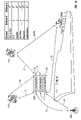
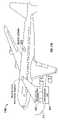
- FIG. 1Aillustrates an example of a communication system for providing redundant communications between one or more master units and one or more remote sensor units.
- FIG. 1Billustrates another example of a communication system between communication devices.
- FIG. 2is a functional block diagram of certain components of a master unit.
- FIG. 3is a functional block diagram of certain components of a remote sensor unit.
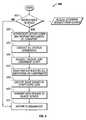
- FIG. 4is a flowchart illustrating certain blocks in a method of processing communications in a master unit.
- FIG. 5is a flowchart illustrating certain blocks in a method of processing communications in a remote sensor unit.
- FIG. 6Ais a data packet that may be used with the communication systems of FIGS. 1A and 1B .
- FIG. 6Bis a data packet that may be used in communicating messages to/from the master units, the central data collection servers and/or the remote sensor units.
- FIG. 7is an example of a data package for communicating between a master unit and a base station.
- FIG. 8is a master unit task assignment script for communicating task assignments to a master unit.
- FIG. 9is an example of a data collection unit housing.
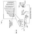
- FIG. 10depicts an example of placement of a data collection unit within a shipping container.
- FIG. 11A to 11Cshow example embodiments of positioning of data collection units for use in the global communication system of FIGS. 1A and 1B .
- the master unitcan be configured to monitor any object, mobile or stationary, including monitoring multiple remote sensor units associated with the objects being monitored.
- the master unitmay be in a fixed location, or attached to a mobile object.
- the master unitcan be configured for monitoring objects that enter and leave the area where it is located.
- the master unitmay act as a parent controller for one or more child devices, wherein the child devices can be remote sensors or monitors of various measurable conditions including environmental conditions, substance identification, product identification and biometric identification.
- the master unitmay be able to discover new remote sensor units as they enter or leave the area where the master unit is located.
- the master unitmay be able to be remotely reprogrammed. The reprogramming may be accomplished with authenticated instructions.
- the remote sensor unitsare configured to communicate with the master unit.
- the communicationcan be over a secure communication link.
- Remote sensorscan be commanded to provide monitored information to the master unit on an as needed basis, on a fixed time basis or in other ways.
- Remote sensor unitsmay be connected to various peripheral measuring devices.
- the central data collection serveris connected to the master unit via one or more communication links.
- the central data collection servercan send instructions to the master unit over the one or more communication links.
- the instructionscan include monitoring task instructions, reprogramming instructions, diagnostic test instructions and others.
- each unite.g., central data collection servers, master units and remote sensor units can communicate over at least two communication links to at least two other entities.
- independent (redundant) encryption key exchangesare used for all messaging between the various units.
- redundant power suppliesare used for the units.
- a processis terminated when its operations are completed.
- a processmay correspond to a method, a function, a procedure, a subroutine, a subprogram, etc.
- a processcorresponds to a function
- its terminationcorresponds to a return of the function to the calling function or the main function.
- FIG. 1Aillustrates an example of an infrastructure of a communication system for providing redundant communications between one or more master units and one or more remote sensor units.
- the example illustratedis a cargo ship with multiple shipping containers 100 .
- the shipping containers 100may each have one or more master data collection units 105 (each container is depicted with one master unit 105 in this example).
- the containerscontain objects (not shown) that may contain remote sensing units (not shown) attached to the objects. Additionally, remote sensing units 110 may be positioned at other areas in and/or outside the containers.
- a devicemay be connected to a plurality of antennae to overcome positioning problems (e.g., containers stacked on a ship).
- the remote sensor units 110 and the master units 105communicate over two or more channels to one or more other communication links to two or more communication devices.
- the master units 105communicate with one or more remote sensor units 110 .
- the master units 105can also communicate with various other communication devices and/or networks, either for the purpose of collecting data or relaying data to another device with a more robust direct communication channel, serving as a peer-to-peer or adhoc-network.
- the communication link 1shows a master unit 105 communicating with another master unit 105 .
- Communication link 2shows a master unit 105 communicating with a satellite relay 115 .
- the communication link 5illustrates a master unit 105 communicating with a land or sea based antenna relay 120 .
- the communication links 2 a and 3depict a remote sensor unit 110 communicating with two relay satellites 115 .
- Communication link 1 adepicts a remote sensor unit 110 communicating with another remote sensor unite 110 (e.g., a relay station).
- the instructions and/or responses to instructionscan be forwarded to the intended remote sensor unit 110 or master unit 105 .
- a master unit 105can communicate with the land or sea based antenna 120 which can then forward the communication to a second master unit 105 via a communication link 5 a.
- Intermediary relay stationsmay also be used in forwarding messages.
- the remote sensor 110 amay communicate a monitoring measurement to the relay satellite 115 on communication link 3 , which the forwards the message to an on-ship intermediary satellite receiver via communication link 6 a .
- the intermediary on-ship receivercan then forward the message to the master unit 105 (e.g., the master unit that requested a measurement from the remote sensor) via communication link 6 .
- Other types of communication links not shown in FIG. 1that can be part of the redundant communication infrastructure include cellular telephone networks, LANs (wired or wireless local area networks), WANs, and wired networks (for fixed location units).
- FIG. 1Billustrates another example of a communication system between communication devices.
- the communication systemcan represent communication flow at multiple levels.
- the master unit 105serves as a data collection server and communicates with one or more of the remote sensor units 110 that serve as trusted monitoring devices.
- the data collection servercan be a central data collection server 125 that communicates with one or more master units 105 that serve as the trusted monitoring devices. Communications can be direct between the data collection server ( 105 or 125 ) and the trusted monitoring devices ( 110 or 105 ). Communications can also be relayed via one or more relay stations such as the relay satellites 115 and the antennas 120 .
- FIG. 2is a functional block diagram of certain components of a master unit, such as the master units 105 discussed above.
- the master unit system 200preferably includes a redundant microprocessor component 202 . However, a single microprocessor unit 202 could be utilized.
- the microprocessor 202may be one or more of any conventional general purpose single—or multi-chip microprocessor such as a Pentium® processor, Pentium II® processor, Pentium III® processor, Pentium IV® processor, Pentium® Pro processor, a 8051 processor, a MIPS® processor, a Power PC® processor, or an ALPHA® processor.
- the microprocessor 202may be one or more of any conventional special purpose microprocessor such as a digital signal processor.
- the microprocessor 202is linked to various other modules on the master unit system 200 with conventional address lines, conventional data lines, and/or conventional control lines for purposes of data transfer, instruction reception and transmission and data processing.
- Memoryis provided by a memory component 204 and/or a data storage unit 206 .
- both the memory component 204 and the data storage unit 206provide redundancy in the form of spatial redundancy (different portions of the same medium), or unit redundancy where two separate devices contain redundant data.
- Memoryrefers to electronic circuitry that allows information, typically computer data, to be stored and retrieved. Memory can refer to external devices or systems, for example, disk drives or tape drives. Memory can also refer to fast semiconductor storage (chips), for example, Random Access Memory (RAM) or various forms of Read Only Memory (ROM), that are directly connected to the processor. Other types of memory include bubble memory and core memory. Memory also includes storage devices (internal or external) including flash memory, optical memory and magnetic memory.
- the master unit system 200is comprised of various modules 208 - 228 .
- each of the modules 208 - 228comprise various sub-routines, procedures, definitional statements, and macros.
- Each of the modules 208 - 228are typically separately compiled and linked into a single executable program. Therefore, the following description of each of the modules 208 - 228 is used for convenience to describe the functionality of the master unit system 200 .
- the processes that are undergone by each of the modules 208 - 228may be arbitrarily redistributed to one of the other modules, combined together in a single module, or made available in a shareable dynamic link library. Further each of the modules 208 - 228 could be implemented in hardware.
- a networking circuitry module 208contains logic and or circuitry for communication of various communication links such as the communication links 1 through 6 and 1 a through 6 a discussed above in reference to FIG. 1A .
- the networking circuitry module 208may include circuitry for communicating over wireless communication links that may comprise, for example, part of a code division multiple access (CDMA or CDMA2000) communication system, a frequency division multiple access (FDMA) system, an orthogonal frequency division multiple access (OFDM) system such as WiMax (IEEE 802.16x), a time division multiple access (TDMA) system such as GSM/GPRS (General Packet Radio Service)/EDGE (enhanced data GSM environment) or TETRA (Terrestrial Trunked Radio) mobile telephone technology for the service industry, a wideband code division multiple access (WCDMA), a high data rate (1xEV-DO or 1xEV-DO Gold Multicast) system, or in general any wireless communication system employing a combination of techniques.
- the networking circuitry module 208may include circuitry for
- An alarm module 210contains circuitry for receiving notification, via pushed messaging or through periodic monitoring of data from various alarm sensors.
- Alarm sensorsmay be linked via wired and or wireless communication links.
- the alarm sensorsmay monitor audible (audio) signals, visual (video) signals, or on/off type of alerts such as door locks, intruder alerts etc.
- An external ports module 212may provide I/O to various external devices including input/output devices, display devices, printers, cameras, antennas and remote sensors. Preferably, redundant wireless communication links are also provided, via the networking circuitry module 208 , for any of the external devices connected via the external ports.
- the wired external devicesare connected to the computer using a standards-based bus system.
- the standards based bus systemcould be Peripheral Component Interconnect (PCI), Microchannel, SCSI, Industrial Standard Architecture (ISA) and Extended ISA (EISA) architectures.
- An air circulation component 214may have multiple input ports for sampling air from various sources. Ducting is connected to the ports to be located in various areas of the monitored area.
- the air intake systemincludes a fan, a vacuum or other means of moving air so as to supply one or more sensors with unadulterated samples. Details of the air intake analysis system are discussed below.
- a global positioning system (GPS) 216is used to track the location of the master unit.
- the GPS modulemay be connected to an external antenna in situations where the master unit is housed in a shielded container or location.
- the GPS systemcan also receive measurements from remote sensor units that contain GPS tracking ability.
- multiple objectscan be tracked by the same master unit.
- multiple sensor units containing GPS capabilitycan combine their satellite signals in order to speed up convergence and capture of the necessary number of GPS satellites. GPS signals may also be combined with other signals to further refine the exact location of the object.
- Instructionsrefer to computer-implemented steps for processing information in the system. Instructions can be implemented in software, firmware or hardware and include any type of programmed step undertaken by components of the system. Instructions received by and transmitted by the master unit 200 are typically encrypted. A digital certificate storage and authentication module 218 is used to establish secure connections with the multiple remote sensor units, relay units, intermediary units and central data collection servers of the global system shown in FIG. 1A . An encryption and decryption module 220 is used to encrypt messages transmitted by and decrypt messages received by the master unit 220 . Redundant encryption keys can be used over the redundant channels for added security. The type of encryption for a given task shall be defined by the Assignment Script discussed below in reference to FIG. 8 .
- An on-board power management module 222is used to monitor batteries, backup batteries, and/or fuel cells as well as external power source reliability and variability. The state of all power sources is monitored at periodic intervals for both quantity and quality so as to get early warning of future operational limitations.
- An external power module 224is used to convert power from multiple sources for use when available.
- the power module 224can sense when the master unit is plugged into various voltage levels, AC and/or DC sources in order to power the unit in multiple areas of the world having different power levels and reliability. Filtering can be used to smooth out power surges in areas where the external power is unreliable. Switching to internal power can be automated when power spikes or power loss is detected. An uninterruptible power supply is preferred. In some embodiments, anomalies in the power supply are logged and reported to the central data collection server.
- the remote control of door/orifice enty/exitcan be monitored/controlled by module 226 .
- the master unitcan control the unlocking and or opening of doors using electro-mechanical, pneumatic devices or other means known to those in the art.
- a suite of remote sensor command and control modules 228 A to 228 Kare used to connect peripherals directly to the master unit or to allow the master unit to interact with the remote sensors.
- the various remote sensor typeswill be presented below. Additional remote sensor suites can be added to the master unit by recognizing the presence of a new remote sensor.
- the new remote sensormay be recognized by monitoring for and receiving an identification signal broadcast by the new remote sensor.
- the identification signalmay contain identification information that identifies a type of sensor, a model number etc.
- the master unitcan conduct authentication of the new remote sensor or transmit the identification information to a central server for evaluation and/or approval to communicate with the new sensor.
- the servercan then send a new assignment script that includes new instructions for adding the new remote sensor to the monitoring schedule of the master unit.
- new remote sensor slotscan be added by remote programming in order to enhance the number of remote sensors that the master unit can recognize and/or command and interact with.
- empty slots in the master devicecan be filled with new sensors or external, remote child sensors units can communicate with the master.
- any sensoris first authenticated prior to communicating with a second device.
- FIG. 3is a functional block diagram of certain components of a remote sensor unit, such as the remote sensor units 105 discussed above.
- the remote sensor unit system 300preferably includes a redundant microprocessor component 302 .
- a single microprocessor unit 302could be utilized.
- the microprocessor 302may be one or more of any conventional general purpose single- or multi-chip microprocessor such as a Pentium® processor, Pentium II® processor, Pentium III® processor, Pentium IV® processor, Pentium® Pro processor, a 8051 processor, a MIPS® processor, a Power PC® processor, or an ALPHA® processor.
- the microprocessor 302may be one or more of any conventional special purpose microprocessor such as a digital signal processor.
- the microprocessor 302is used as the main computing source of various other modules on the remote sensor unit system 300 with conventional address lines, conventional data lines, and/or conventional control lines for purposes of data transfer, instruction reception and transmission and data processing.
- the remote sensor unitacts as a slave device to the master unit, e.g., only doing a subset of the master device functions, e.g., not communicating with the central data collection server directly.
- Memoryis provided by a memory component 304 and/or a data storage unit 306 .
- both the memory component 304 and the data storage unit 306provide redundancy in the form of spatial redundancy (different portions of the same medium), or unit redundancy where two separate devices contain redundant data.
- Memoryrefers to electronic circuitry that allows information, typically computer data, to be stored and retrieved. Memory can refer to external devices or systems, for example, disk drives or tape drives. Memory can also refer to fast semiconductor storage (chips), for example, Random Access Memory (RAM) or various forms of Read Only Memory (ROM), that are directly connected to the processor. Other types of memory include bubble memory and core memory. Memory also includes storage devices (internal or external) including flash memory, optical memory and magnetic memory.
- the remote sensor unit system 300is comprised of various modules 308 - 324 .
- each of the modules 308 - 324comprise various sub-routines, procedures, definitional statements, and macros.
- Each of the modules 308 - 324are typically separately compiled and linked into a single executable program. Therefore, the following description of each of the modules 308 - 324 is used for convenience to describe the functionality of the remote sensor unit system 300 .
- the processes that are undergone by each of the modules 308 - 324may be arbitrarily redistributed to one of the other modules, combined together in a single module, or made available in a shareable dynamic link library. Further each of the modules 308 - 324 could be implemented in hardware.
- a networking circuitry module 308contains logic and or circuitry for communication of various communication links such as the communication links 1 through 6 and 1 a through 6 a discussed above in reference to FIG. 1A .
- the networking circuitry module 308may include circuitry for communicating over wireless communication links that may comprise, for example, part of a code division multiple access (CDMA or CDMA2000) communication system, a frequency division multiple access (FDMA) system, an orthogonal frequency division multiple access (OFDM) system such as WiMax (IEEE 802.16x), a time division multiple access (TDMA) system such as GSM/GPRS (General Packet Radio Service)/EDGE (enhanced data GSM environment) or TETRA (Terrestrial Trunked Radio) mobile telephone technology for the service industry, a wideband code division multiple access (WCDMA), a high data rate (1xEV-DO or 1xEV-DO Gold Multicast) system, or in general any wireless communication system employing a combination of techniques.
- the networking circuitry module 308may include circuitry for
- An external ports module 312may provide I/O to various external devices including input/output devices, display devices, printers, cameras, antennas and remote sensors.
- redundant wireless communication linksare also provided, via the networking circuitry module 308 , for any of the external devices connected via the external ports.
- the wired external devicesare connected to the computer using a standards-based bus system.
- the standards based bus systemcould be Peripheral Component Interconnect (PCI), Microchannel, SCSI, Industrial Standard Architecture (ISA) and Extended ISA (EISA) architectures.
- An air circulation component 314may have multiple input ports for sampling air from various sources. Ducting is connected to the ports to be located at various locations of the monitored area.
- the air intake systemincludes a fan, a vacuum or other means of moving air so as to supply one or more sensors with unadulterated samples.
- a global positioning system (GPS) 316is used to track the location of the remote sensor unit.
- the GPS modulemay be connected to an external antenna in situations where the master unit is housed in a shielded container or location.
- the GPS systemcan also receive measurements from other remote sensor units that contain GPS tracking ability and are in range of the remote sensor unit. Signal levels can be used to estimate ranges to other remote sensor units containing GPS modules 318 .
- multiple sensor units containing GPS capabilitycan combine their satellite signals in order to accelerate acquisition of the necessary number of GPS satellites.
- a digital certificate storage and authentication module 318is used to establish secure connections with the multiple remote sensor units, relay units, intermediary units and central data collection servers of the global system shown in FIG. 1A .
- An encryption and decryption module 320is used to encrypt messages transmitted by and decrypt messages received by the master unit 220 . Redundant encryption keys can be used over the redundant channels for added security.
- An on-board power management module 322is used to monitor batteries, backup batteries, and/or fuel cells as well as external power source reliability and variability. In some embodiments, anomalies in the power supply are logged and reported to a controlling master unit or forwarded to another communication device as in a peer-to-peer and/or adhoc network.
- An external power module 324is used to convert power from multiple sources for use when available.
- the power module 324can sense when the master unit is plugged into various voltage levels, AC and/or DC sources in order to power the unit in multiple areas of the world having different power levels and reliability. Filtering can be used to smooth out power surges in areas where the external power is unreliable. Switching to internal power can be automated when power spikes or power loss is detected. An uninterruptible power supply is preferred.
- FIG. 4is a flowchart illustrating certain blocks in a method of processing communications in a master unit.
- the process 400typically starts in a hibernation state.
- the master unitthen transfers out of the hibernation state to step 410 in order to monitor one or more communication links for incoming instructions (e.g., from the central data collection server 125 in FIG. 1B ). Monitoring for incoming instructions at step 410 can be continuous, periodic, or random. If no instruction is received at step 410 , the process 400 proceeds to step 415 where it returns to the hibernation state. If instructions are received at step 410 , the process 400 proceeds to step 420 .
- Step 420involves authenticating the server from which the received instructions originated. Authentication can include known techniques such as digital IDs with corresponding digital signatures. If the authentication shows that the received message is authentic, the process 400 continues to step 425 . However if the authentication shows the instructions to be false, the process 400 can return to the hibernation state or return to step 410 to detect another incoming instruction. Details of authentication will be discussed below in relation to FIGS. 6 and 7 .
- the processcan continue at one or more other steps 430 to 445 , depending on the received instructions.
- the instructionsare preferably encrypted and the authenticating device decrypts the instructions before performing and/or instructing other devices to perform the tasks.
- the instructionmay direct the master unit to conduct diagnostic tests, step 430 , query and authenticate subsystem modules, components and/or remote sensor units, step 435 , execute tasks defined in a script, step 440 , and/or transmit data packages to one or more remote servers. After completing the instructed tasks the process 400 generally proceeds to step 415 and returns to the hibernation state. Details of the various actions taking place in the steps shown in FIG. 4 will be discussed below in relation to the individual tasks performed by the master unit.
- Instructions received by the master unit while performing the process 400may require the master unit to transmit instructions to one or more of the remote servers. Additionally, the master unit may be programmed to transmit instructions to remote sensors autonomously without receiving command instructions.
- FIG. 5is a flowchart illustrating certain blocks in a method of processing instructions in a remote sensor unit.
- the instructionspertain to sampling a sensor measurement and transmitting the sampled data to the master unit.
- the sensor unitcan also be instructed to perform processing to that shown in FIG. 4 (e.g., diagnostic tests, reprogramming, etc.)
- the process 500typically starts in a hibernation state.
- the master unitthen transfers out of the hibernation state to step 510 in order to monitor one or more communication links for incoming instructions (e.g., from the master unit 105 in FIGS. 1A and 1B ). Monitoring for incoming instructions at step 510 can be continuous, periodic, or random. If no instruction is received at step 510 , the process 500 proceeds to step 515 where it returns to the hibernation state. If instructions are received at step 510 , the process 500 proceeds to step 520 .
- Step 520involves providing the master unit with the remote sensor unit's digital ID/ signature, thus authenticating the remote sensor to the master unit that sent the instructions.
- Authenticationcan include known techniques such as digital IDs with corresponding digital signatures.
- the master unitcan perform the authentication of the remote sensor's response and determine whether or not to use the forthcoming sensor data. Authentication of the master unit to the remote sensor can also be done at step 520 .
- the master unitwill provide a digital ID/signature in the instruction message received at step 510 and the remote sensor will authenticate the master unit. This two-way type of authentication protects both the master unit and the remote sensor from being hacked. If the authentication shows that the received message is from an authentic master unit, the process 500 continues to step 525 . However if the authentication shows the instructions come from an unauthentic master unit, the process 500 can return to the hibernation state or return to step 510 to detect another incoming instruction. Details of authentication will be discussed below in relation to FIGS. 6 and 7 .
- the processcan continue at step 525 where the remote sensor unit samples one or more of the measurements that it is equipped to sample.
- the remote sensormay be instructed to sample for a certain time period or at a certain interval. If the sampling is to be terminated at a certain time, as per predetermined or received instructions, the sampling is stopped at step 530 .
- the remote sensor unitmay periodically transfer the sampled data to the master unit.
- Sampled data that is to be transferred to the master unitis preferably encrypted at step 535 .
- the remote sensor unitmay proceed to step 540 to authenticate the master unit on the one or more communication channels that it will transmit the sampled data on.
- the process 500continues at step 545 where the sensor data is transmitted to the master unit.
- the transmitted datacan be digitally compressed.
- Various compression algorithmscan be used to remove the redundancy in the transmitted data, thereby saving time, bandwidth, and/or power.
- the process 500may return to the hibernation state to receive more instructions, or return to sampling the sensor data at step 530 .
- the remote sensor(or any other transmitting device) is configured to confirm receipt of the data by the master unit (or any other receiving device).
- the remote sensorcan retransmit the data over a different communication path (e.g., one of the available redundant communication links). Redundant communication links may include any of those discussed above. Details of the other actions taking place in the steps shown in FIGS. 4 and 5 at the remote sensor unit will be discussed below in relation to the individual tasks performed by the sensor unit.
- FIG. 6Ais a data packet that may be used in communicating messages to/from the master units, the central data collection servers and/or the remote sensor units.
- the packet 600includes a packet header 602 , a packet body 604 and a packet checksum 606 .
- the packet 600is preferably encrypted as discussed above.
- the packet header 602can contain information necessary for identifying such things as the length of the packet, the ID of the recipient of the packet, the data stream ID that the packet is a part of and other information known to those of skill in the art.
- the packet body 604generally contains the message of the packet.
- the packet body 604may contain instructions as discussed above, sensor measurement data etc.
- the packet body 604comprises digitally compressed information.
- the packet checksum 606contains encoded information, e.g., a cyclic redundancy check (CRC), which is used to determine the integrity of the packet when the packet is received.
- the checksummay protect the integrity of data by being used to detect errors in data that are sent through space (e.g., over a communication link) or time (e.g., storage).
- a checksummay be calculated by simply adding up the components of a message or a portion of a message.
- a checksummay also be based on the body of the packet containing the message or a portion of the message.
- Checksumsmay be an integer number of bits or bytes.
- a checksummay also be based on a cryptographic hash function. Unlike a simple additive checksum, a hash function may enable detection of a reordering of the bits in a message, inserting or deleting zero-valued bits or bytes and multiple errors that cancel each other out.
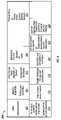
- FIG. 6Bis a data packet that may be used in communicating sampled sensor data from the sensor unit to the master unit as in step 545 of the process 500 .
- the packet 600 Ahas a packet header 602 that includes a digital signature field 608 , a task ID field 610 and a sensor ID and version field 612 .
- the signature field 608contains the digital signature that is used to authenticate the remote sensor to the master unit as in step 520 of the process 500 .
- the Task ID field 610contains a sequence number that is used by the master unit to identify which task this message contains a response for.
- the master unitsmay be monitoring many remote sensors, each of which may have several task IDs.
- the size of the task ID field 610if a fixed number of bits, should be large enough to cover the largest number of simultaneous tasks that the master unit expects to submit.
- the task ID field 610could be variable so as to allow expansion of the number of allowable task IDs to grow as the number of remote sensors which the master unit is control of grows.
- the sensor identification field 612contains information identifying the identity of a particular remote sensor.
- the sensor identification field 612may contain indexed information that identifies a number of items such as, for example, the type of sensor (e.g., a temperature sensor, an air sampling sensor, a biometric sensor, etc.), the serial number of the sensor to distinguish from other sensors of the same type, and the version number of the sensor to distinguish software and/or hardware versions.
- the packet 600 Aalso contains fields 614 to 618 .
- Field 614contains the start date and time when the sampled measurements were sampled.
- the field 616contains the sampled data that was sampled by the sensor from the start time to the stop time.
- the field 618contains the stop date and time for the sampled data.
- Field 620contains the checksum that is used by the master unit in verifying the integrity of the data packet 600 A. If the integrity is determined to be erroneous, then the master unit may request that the remote sensor retransmit the message.
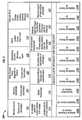
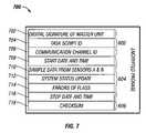
- FIG. 7is a data packet that may be used in communicating data from the master unit to the central date collection server as in step 445 of the process 400 .
- the packet 700has a packet header 602 that includes a digital signature field 702 , a task script ID field 704 and a communication channel ID 706 .
- the signature field 702contains the digital signature that is used to authenticate the master unit to the central data collection server.
- the task script ID field 704contains a sequence number that is used by the central data collection server to identify which task script this message contains a response for. Task scripts will be discussed below in relation to FIG. 8 . As with the task ID field 610 , the size of the task script ID field 704 , if a fixed number of bits, should be large enough to cover the largest number of simultaneous task scripts that may be active simultaneously.
- the Communication channel ID field 706is used for audit trail tracking purposes. By combining the communication channel ID field 706 with the master unit ID (contained in the master unit digital signature field 702 . Maintaining these audit trails may allow identification of compromised or unreliable devices and/or compromised communication channels. Maintaining audit trails may also allow identification of which information was sent by which device and when it was sent.
- the packet body 604 of the packet 700contains the fields 708 to 716 which contain the responses to the various script tasks that the central data collection unit requested of the master unit.
- the field 708contains the start date and time for which the message contains monitoring information.
- the field 710contains the data sampled from various sensors (two sensors A and B in this example).
- the field 712contains system status information. This system status information may be the result of diagnostic test done on the master unit modules and/or components, or they may be the status of remote sensors that the master unit is the controlling parent of.
- Field 714contains information regarding errors or flags identifying the errors. Such errors may include errors in previously received task script instruction messages.
- Field 716contains the stop date and time for the data contained in the packet 700 .
- Field 718contains the checksum that is used by the master unit in verifying the integrity of the data packet 700 . If the integrity is determined to be erroneous, then the central data collection unit may request that the remote sensor retransmit the message.
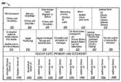
- FIG. 8is a master unit task assignment script for communicating task assignments to a master unit.
- the headercontains 10 fields containing information identifying the master unit that the script is targeted for.
- the digital signature fieldis used for authentication of the central data collection server (or other issuing device) that issued the script instructions.
- Other fields in the headermay include a various task classifications including a customer ID, a project ID, and the targeted master unit ID.
- Other fields in the headermay identify the location of the master unit including a vessel or structure ID and/or a location ID.
- Other header fieldsmay include scheduling or sequence number information such as a logistics number field, a service start and/or stop time field, a field designating a previous script to be replaced by the current script and a script version number.
- the body of the task assignment scriptassigns the tasks to the master unit in the form of an inventory list of all actions and devices approved to participate (or be utilized) in the current job.
- the body fields 1 through 14list monitoring tasks to be performed utilizing preferably two remote sensors, designated sensor A and sensor B in this script.
- the sensors A and Bmay be pre-designated in a previous script or listed in the current script (not shown in FIG. 8 ).
- the master unitwill record the various measurements of the service description tasks listed in the body of the task assignment script and log in the other portions of the inventory check list including a comparison check of sensor A to sensor B (e.g., for identification of a faulty sensor), a sample interval time, a transmit interval time, a date an time stamp that the measured data was transmitted back to a central data collection sever, a field identifying whether the data was logged locally, as well as records indicating whether or not the encryption key handshake and authentication tasks were completed successfully.
- a secure system for remotely gathering informationis formed.
- the master unit(or a data collection server) monitors data received from one or more trusted sensors for the purposes of determining an alarm condition.
- the master unitmay receive an indication of a state of alarm from a remote sensor or a sensor connected directly to the master unit via one or more of the sensor suite ports 228 A to 228 K.
- the master unitmay also make a determination of an alarm condition based on data received from remote sensors.
- the data received from the remote trusted sensorsis compared against a range of acceptable values. The master unit performs a self-diagnosis of the data received from the one or more trusted sensors in order to prevent false alarms.
- One method of performing the self-diagnosisinvolves receiving similar data from redundant remote trusted sensors.
- a majority ruleis used where an alarm is issued if a majority of the similar sensors are transmitting data that is outside of the acceptable levels. If there are 2 redundant remote sensors, then the majority rule may require that both sensors measure unacceptable levels. If there are three redundant sensors, then receiving unacceptable levels from two out of the three will result in a determination of a state of alarm.
- the self diagnosisis based on a state of reliability of the trusted monitor that the data is received from.
- the master unitmay require additional data (e.g., from other sensors or a retransmission of data from the same sensor) to make the self-diagnosis.
- additional datae.g., from other sensors or a retransmission of data from the same sensor.
- Other self-diagnosis techniquesthat can indicate a corrupt or unreliable source of information include various forms of error checking such as cyclic redundancy checks and/or checksums.
- Another variation of diagnosiscomprises running through a standardized set of routines or measuring something of a known value. The measured result is compared to known values in order to detect errors or to calibrate the device.
- the central data collection unitcan perform similar alarm state determinations as those presented here, involving determining an alarm state of one or more master units and/or remote sensors.
- the alarm conditioncan have more than two states (other than an alarm state and a non-alarm state).
- the alarm statemay have several different levels of risk, such as for example, 3, 4, 5, 6, or more levels of risk with the severity of the risk condition increasing with each increase in alarm level.
- alarm level 1may be a condition where no received data lies outside the acceptable ranges (e.g., a no alarm state)
- level 2may be if the received data from one or more sensors is approaching an unacceptable level
- level 3may be where the received data has exceeded the acceptable level but only by a small amount and the level 4 condition may cover when the received data exceeds the unacceptable level by more than the level 3 amount.
- a monitoring devicee.g., a master unit or a central data collection unit
- a method of determining tampering of a deviceinvolves receiving information from a motion sensor. If a trusted device is a stationary (or mostly stationary) device, the a motion sensor can be monitored in order to determine possible tampering. For a stationary device, any motion above the noise level of the motion sensor may be used as an indication that someone or something has attempted to move or at least make contact with the stationary device. For other devices, a movement outside of a defined localized or proximal area may be an indication of tampering.
- CRCsare typically used to identify whether data has been modified between where it originated (e.g., at a trusted remote sensor) and where it was received (e.g., at a master unit and our a data collection server).
- Jamming signalsmay be detected by the resulting corrupt data (e.g., failures of CRCs or checksums).
- Jamming signalsmay also be detected directly by measuring the level of RF energy within a certain bandwidth of frequencies. High levels of RF energy within a certain bandwidth may be used as an indication that the certain bandwidth is being selectively jammed. Monitoring a plurality of sensors may add confidence to the positive (or negative) detection of jamming.
- Redundancy of information sources, processors, power supplies, communication links, memory, and communication devices of all kindsmay add security and robustness to the information monitored in the monitoring system.
- Redundant processorsmay be monitored and if one is determined to be corrupted, the second one may serve as a temporary backup until the corrupt processor is fixed and/or replaced.
- Redundant sensorsmay be used to reduce the risk of false alarm by using a majority rules method of determining and issuing an alarm state as discussed above.
- Redundant power suppliesmay be utilized to lower the likelihood of power failure.
- Redundant communication linksoffer many useful tools for increasing the security and thus the trustworthiness of the monitoring system of some embodiments.
- the best choicecan be determined in several ways. In one method, battery strength may be used in choosing which redundant communication links to use. If the on-board power management component 222 or 322 determines that the battery level of a master unit or remote sensor is low, the communication link requiring the lower transmit power may be the better choice. If battery life is not a problem, or an external power source with indefinite power availability is present, then the most power demanding communication link may be the best choice since it may prove more reliable and more secure. If a battery level is detected to be low, the power management component may activate a recharge state. Recharging can include use of an external AC or DC power supply, solar power generation, wind power generation or any of other power generating techniques known to those of skill in the art.
- received signal strengthmay be used as a deciding factor in which communication link to used between two communication devices.
- the signal to noise ratio (SNR) of received datamay be used as an indicator of a reliable channel.
- One artifact of jammingmay be a low SNR measurement of received data.
- SNRmay be used to detect jamming on a communication link. By monitoring the SNR of all available communication links, the communication link with the highest SNR may be chosen as a best link between two communication devices.
- the urgency of the message and/or the security level of the information level being sentmay be crucial in deciding which communication link to use.
- the estimated time to transmit and receive the messagemay be most important. If time is more critical then security, then a communication link that utilizes an encryption and/or authentication scheme that requires several handshakes may be less desirable than a communication link that has a simple fast way of establishing a link.
- Some types of informationmay call for higher levels of encryption and the communication links with the best encryption security may be chosen first.
- Integrity check failuresmay be an indication of equipment failure (e.g., an obstructed antenna), jamming, power failure or other system failures. Redundant antennas may be employed to overcome equipment failure such as an obstructed antenna. Feedback of integrity check results may be used as an indication than one antenna is not as effective as another and the ineffective antenna may not be used until the effectiveness returns.
- equipment failuree.g., an obstructed antenna
- Redundant antennasmay be employed to overcome equipment failure such as an obstructed antenna.
- Feedback of integrity check resultsmay be used as an indication than one antenna is not as effective as another and the ineffective antenna may not be used until the effectiveness returns.
- Redundant communication linksneed not be utilized simultaneously, although this is one option. Robust communications between two or more devices can be accomplished using a single communication link. Robust communications can be more likely if all data packets are encrypted and authenticated (e.g., signed with a digital signature). The likelihood of losing data can be reduced if large internal memory storage is provided for all communication devices. Redundant memory also reduces likelihood of loss of information due to storage device failure. Frequent handshakes between devices, for example frequent data receipt acknowledgements (Acks) can be used to verify receipt of data. Other methods of providing robust communication links will be apparent to those of skill in the art.
- Acksfrequent data receipt acknowledgements
- the master unitmay revert to the beginning of the task being performed when communication was interrupted and restart the task.
- both devicesmay keep a log of actions taken (for example, see the master unit task assignment script shown in FIG. 8 ) and communication may be reestablished at the last uncompleted task in the list.
- redundant sensorscan provide an indication of a location of an event or an object. For example, if there is a set of remote sensors for detecting radiation sources, a location of a source of radiation may be pinpointed by interpolating the strengths of the radiation measurements of each sensor. A radius of possible locations may be estimated for a given measurement and estimates from three remote sensors can be used to triangulate a two dimensional position of the source of the radiation. Four remote sensors can be used to located an object in three dimensions. Other examples include temperature sensors used to locate heat sources, and air quality sensors used to locate sources of contaminants.
- Another exampleuses multiple GPS receivers to more quickly acquire the number of satellites needed form establishing a GPS location measurement.
- the geographic diversity offered by spreading GPS receivers over an areadecreases the likelihood of all the receivers being blocked (e.g., by buildings etc.).
- the remote sensorscan be located in any of the communication devices discussed above including master units, remote sensors and data collection servers.
- Each of the packageshas at least one sensor measuring at least one sensed input condition.
- the input conditionmay be a location measurement, an altitude measurement, a temperature, magnetic field measurement or other measurement.
- Each of the packagesalso has at least one telemetric communicator configured to provide (e.g., transmit) the sensed input to a coordinating device.
- the coordinating deviceis configured to process the sensed information.
- the telemetric communicatoris configured to communicate the sensed information over a first communication link to the coordinating device.
- the telemetric communicatoris configured to transmit the sensed information to another telemetric communicator contained in another one of the packages.
- the telemetric communicatormay still communicate to the coordinating device via an adhoc network of one or more packages. This type of networking can enable the detection of an object being moved (e.g., being stolen from a warehouse) to be identified and monitored for tracking purposes.
- inventionsprovide a system that can track not only the location of one or more objects, but may also verify that the proper individual is in possession of the object.
- These embodimentsinclude an environmental sensor configured to detect environmental information about an object.
- the environmental sensormay detect a magnetic field, a radio field or some other field associated with the object.
- a product identification sensoris configured to receive information to identify the object.
- the objectmay contain an RFID tag to transmit to the product identification sensor for identification.
- biometric sensorconfigured to receive biometric information about an individual. In one aspect the biometric information is kept on record in a list of individuals permitted access to the object.
- the systemmay also include a GPS sensor configured to receive GPS location information.
- sensorsare all accessible to be monitored by a trusted electronic device such as, for example, the master control unit or the data collection server discussed above.
- the monitoring devicecan perform a diagnosis of the sensed information to assess whether the object being monitored is in danger of being moved and or tampered with by someone other than the permitted individuals.
- FIG. 9shows an example of a housing of a data collection unit.
- the data collection unit 900may be a data collection server, a master unit or a remote sensor.
- the unit 900 in FIG. 9contains an antenna 905 and an LED display 910 .
- the data collection unit 900also contains two air sampling tubes 915 .
- the underside of the housingcontains at least two pressure or proximity activated anti-tamper switches 920 , a fastener 925 to lock to the mounting base and a bus connector 930 to attach to an optional external power supply, keyboard, display device or similar peripheral.
- the housing of the unit 900is of Tempest construction and shielded to resist external measurement devices from gaining access to magnetic and or electric emissions.
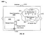
- FIG. 10depicts an example of placement of a data collection unit within a shipping container.
- the data collection unit 900is mounted to a mounting base 1025 .
- the mounting base 1025may include one or more external power connections 1020 , and be attached to the container 1000 so as to be difficult to remove.
- the container 1000preferably includes multiple antenna 1015 (external and/or internal), where the container in FIG. 10 includes three external antenna.
- the multiple antennacan provide directional diversity for transmission and reception of signals in case one or more antenna are obstructed.
- the container 1000can also comprise multiple internal sensors such as a passage control sensor 1005 .
- the passage control sensor 1005can permit individuals or objects with proper identification devices (biometrics, smart cards, RFID cards etc.) to enter the container 1000 or an area 1030 within the container.
- a door sensor 1010may also indicate whether a door of the area 1030 within the container has been opened.
- Other sensorsmay include sensors for detecting the presence of certain objects within the container 1000 .
- Such sensorsmay include ultrasound pattern sensors, radar or x-ray pattern sensors and others.
- the data collection unit 900may use comparison of the ultrasound, x-ray and/or radar patterns to detect changes in the content and/or layout of objects in the container. This can allow for the detection of objects added, moved and/or removed from the container 1000 .
- FIGS. 11A to 11Cshow other example embodiments of places for positioning of data collection units.
- FIG. 11Ashows positioning of the data collection unit 900 within an airliner 1100 .
- FIG. 11Bshows positioning of the data collection unit 900 within an automobile 1120 .
- FIG. 11Cshows positioning of the data collection unit 900 within a building 1130 .
- the embodiment in FIG. 11Cincludes an audio capture device 1132 and a video capture device 1134 that can be used to monitor audio and video/image data (e.g., of people entering and/or leaving the building 1130 .
- a central server of the monitoring systemis provided information such as company information, product description and ID numbers (e.g. manifest), safety disclosures, customs disclosures, financial disclosures and receiver party information about the various items in the container.
- informationsuch as company information, product description and ID numbers (e.g. manifest), safety disclosures, customs disclosures, financial disclosures and receiver party information about the various items in the container.
- the central servermay also be provided with biometric data of authorized personnel permitted to access the container.
- Authorized personnelmay have a hand-held-device (HHD) that is configured to communicate with a monitoring system in the container.
- HHDhand-held-device
- Upon approaching the container an authorized personcan scan the container's identifying information with the HHD at which point an authorization process determines whether to issue an electronic authorization key.
- the authorization processmay include the authorized personnel scanning a biometric fingerprint with the HHD.
- the HHDcan then perform an authentication process based on the biometric scan. If the authentication process is successful, the key can be transmitted to the Master Controller located inside the container.
- the Master Controllerreceives the key and compares it to the most recent Job Assignment Script (JAS) received from the backend server. If the key codes match, the MC sends a signal to the solenoid to unlock the door of the container and simultaneously starts image capture from both the internal and external cameras.
- the camerasare remote sensors that the MC is in communication with. The images are stored to the local disk memory of the MC and every 100th frame may be relayed to the central server.
- the personnelWhen the authenticated personnel enters the container, he may install the necessary sensors depending on the contents of the container.
- the personnelinstalls radiological sensors, one sensor in each corner of the container and attaches special ducting connected to the MC to pull air from several locations. He first scans each sensor device with the HHD, mounts the sensors securely in place, then transmits the data to the MC with the HHD.
- the MCcompares the sensor codes to the JAS to verify authenticity and instructs each sensor to conduct a self-diagnosis and tamper check.
- the MCperforms a complete self diagnostic routine of all sensors and systems, then sends the results to the central server.
- the serverwill respond to the MC with approval to reseal the container.
- an authorized personnelUpon arrival at the loading dock, an authorized personnel scans his personal and corporate ID badges on the scanner mounted on the container door. The codes are passed to the MC and compared with the values in the JAS. If the key codes match, the MC sends a signal to the solenoid to unlock the door of the container and simultaneously starts image capture from both the internal and external cameras.
- the supervisorcloses the container doors, scans his ID cards and enters a code confirming the loading is complete.
- the messageis forwarded to the MC which then sends a signal to activate the solenoid thus locking the door.
- the MCperforms an integrity check of all locks and orifice sensors, takes a baseline sample from all sensors activated as defined by the JAS. The results are relayed to the central server. If all data is in conformance, the server issues an authorization key to the MC which in turn illuminates green LEDs at several locations around the exterior of the container. At this point, the container is ready to be transported to the shipping terminal.
- the trucking companyPrior to picking up the container, the trucking company provides the central server with information including the truck ID number, the driver ID number, the relevant container ID and the shipper ID. An electronic authorization key is then transferred to the driver's HHD.
- the driverUpon arrival at the Wang facility, the driver scans his index finger on his HHD, then scans the truck ID tags, the container ID and the Wang facility ID. The information is relayed to the MC in the container.
- the MCcompares the information and keys to those received in the last JAS, and determines if they are consistent. In this case, the driver was replaced at the last minute and authorization was not received.
- the LEDs on the containerturn red and the HHD instructs the driver to contact his management. His management repeats the registration procedure using his ID, and the central server issues new instructions to his HHD.
- the container's MCWhen the container's MC detects movement due to the truck moving, it starts the transportation section of the JAS.
- GPS antennaare scheduled to collect route information and the full range of environmental sensors are sampling every five minutes inside the container.
- Both the shipping terminal operator and the ship captaincan perform similar procedures as that of the trucking company above such that accountability for the container is never in question.
- the JAS for this particular container shipmentdictates the following tasks: 1) Sample environmental once every 15 minutes, 2) Capture one image frame from each camera every five minutes, and 3) Transmit all samples to server once per hour.
- the MC for this containerauthenticates itself with a neighbor MC and requests relay which in turn does the same until a container is found with clear access and a strong signal to the satellite or relay antenna.
- the shipDuring the voyage to the destination port, the ship encounters a heavy storm with 30 foot seas.
- the MC's motion sensorsdetect pitching in excess of 30 degrees at 20 second intervals. As this value is well outside the norm (the acceptable ranges dictated by the JAS), the MC queries adjacent containers for redundant motion readings and determines that the reading is not in error nor is it significantly different than neighboring containers (an indication that the container is not being stolen).
- the cameras and audio sensorscan record video and audio to detect shifting cargo that may result in product damage.
- authorized personnel of the receiving companycan logon to the central server to track developments along the way.
- the authorization informationis relayed to the container's MC where it performs an authorization process to determine whether to issue an electronic key.
- the MCmay consult with the server.
- the Master Controllerreceives the key and compares it to the most recent Job Assignment Script (JAS) received from the backend server. If the key codes match, the MC sends a signal to the solenoid to unlock the door of the container and simultaneously starts image capture from both the internal and external cameras. The images are stored to the local disk memory and every 100th frame is relayed to the server.
- JSJob Assignment Script
- the monitoring system in this exampleis used as a sentry system for the office building.
- the central servermay be provided with information including company identifying information, business description and employee ID numbers, safety disclosures, structural disclosures, financial disclosures and vendor information.
- a security personnel downloads authorization information to a handheld devicethen scans his index finger to confirm identity.
- the HDDinstructs him to retrieve a new device from SecureTech's inventory with ID nr 98765.
- the security personnelscans the box seal then performs a visual integrity inspection and enters his findings to the HHD. He then transmits the information to the sentry system Master Controller (MC) which performs an authorization process with a remote server to determine whether to issue an electronic key. If successful, the key is transmitted to the Master Controller along with its first Job Assignment Script (JAS).
- MCsentry system Master Controller
- the Master Controllerreceives the key and compares it to the most recent Job Assignment Script (JAS) received from the backend server. If the key codes match, the MC sends a signal to the solenoid to unlock the housing of the MC.
- JSJob Assignment Script
- the security personnelthen proceeds to follow instructions provided by the HDD to perform the following tasks:
- the security personnelscans each device with the HHD, mounts them securely in place, then transmit the data to the MC.
- the MCcompares the sensor codes to the JAS to verify authenticity and instructs each sensor to conduct a self-diagnosis and tamper check.
- the MCperforms a complete diagnostic routine of all sensors and systems, then sends the results to the remote server over both a wired and wireless link (redundant communication links). If all is in order, the server will respond with an activation key and issue a new JAS to the MC.
- exterior camerasdetect a middle-aged man just outside the door for prolonged periods of time on three days in the same week.
- the main exterior camera focused on the entrancebecame occluded (11:22:28).
- the MCreferenced the backup measures specified in the JAS and immediately acted to reposition internal camera 4 in the lobby to point in the direction of the main entrance.
- Two minutes later (11:24:21)a heavily disguised person entered the lobby with a large suitcase. Since these two events fall outside the normal operating ranges for these two measurements as defined in the most recent JAS, the data is immediately relayed to the central server via both wired and wireless connections.
- the MCdetects abnormally high electromagnetic interference. As a result, the ID badge scanner malfunctions and permits an unauthorized person to slip into the main lobby. Already on heightened alert, the MC forwards the event immediately to the server and receives an instant response to shut down elevator operation and lock all exterior doors. All security personnel are alerted to the breach and the intruder is captured. This example is meant only to describe the varied monitoring methods that some embodiments can provide.
Landscapes
- Engineering & Computer Science (AREA)
- Physics & Mathematics (AREA)
- General Physics & Mathematics (AREA)
- Business, Economics & Management (AREA)
- Computer Security & Cryptography (AREA)
- Theoretical Computer Science (AREA)
- Signal Processing (AREA)
- Computer Networks & Wireless Communication (AREA)
- Software Systems (AREA)
- General Engineering & Computer Science (AREA)
- Economics (AREA)
- Computing Systems (AREA)
- Strategic Management (AREA)
- Artificial Intelligence (AREA)
- Tourism & Hospitality (AREA)
- Development Economics (AREA)
- Marketing (AREA)
- General Business, Economics & Management (AREA)
- Health & Medical Sciences (AREA)
- Computer Hardware Design (AREA)
- Human Resources & Organizations (AREA)
- General Health & Medical Sciences (AREA)
- Mathematical Physics (AREA)
- Evolutionary Computation (AREA)
- Automation & Control Theory (AREA)
- Entrepreneurship & Innovation (AREA)
- Emergency Management (AREA)
- Medical Informatics (AREA)
- Quality & Reliability (AREA)
- Data Mining & Analysis (AREA)
- Operations Research (AREA)
- Fuzzy Systems (AREA)
- Finance (AREA)
- Accounting & Taxation (AREA)
- Computer Vision & Pattern Recognition (AREA)
- Primary Health Care (AREA)
- Computational Linguistics (AREA)
- Game Theory and Decision Science (AREA)
- Toxicology (AREA)
- Remote Sensing (AREA)
Abstract
Description
- 1. Open the MC housing
- 2. Install one modular sensor controller inside the MC to detect proprietary equipment tags.
- 3. Connect the MC to pre-existing devices in the building:
- a. ID card readers
- b. Proprietary tag reader - sensor heads
- c. Cameras
- d. Door sensors
- e. Elevator activity sensors
- f. Wide-area microphones
- g. Portable x-ray bag scanner
- h. Air-ducting from all entry passages to the MC input portal.
- 1. The MC conducts a self-diagnosis of all critical components and stores the results;
- 2. Outbound data is assembled into a list of files and compressed to one package.
- a. Camera frames are synchronized with corresponding date/time
- b. Camera frames are linked to Lat/Long of building as well as position of the anomaly within a pre-defined grid for the space in question.
- 3. The JAS is consulted for the current encryption parameters and the above package is encrypted accordingly.
- 4. The message is digitally signed using the remote server's key
- 5. Identical copies of the package are sent via a wired and cell connection.
- 6. The MC waits for notice of successful receipt from the remote server.
Claims (6)
Priority Applications (7)
| Application Number | Priority Date | Filing Date | Title |
|---|---|---|---|
| US11/418,380US7656286B2 (en) | 2005-05-03 | 2006-05-03 | Trusted monitoring system and method |
| US12/641,139US20100090822A1 (en) | 2005-05-03 | 2009-12-17 | Trusted monitoring system and method |
| US13/724,942US8830053B2 (en) | 2005-05-03 | 2012-12-21 | Trusted monitoring system and method |
| US14/480,362US20160019384A1 (en) | 2005-05-03 | 2014-09-08 | Trusted monitoring system and method |
| US15/287,464US10504349B2 (en) | 2005-05-03 | 2016-10-06 | Trusted monitoring system and method |
| US16/706,445US20200118405A1 (en) | 2005-05-03 | 2019-12-06 | Trusted monitoring system and method |
| US17/447,389US20220237997A1 (en) | 2005-05-03 | 2021-09-10 | Trusted monitoring system and method |
Applications Claiming Priority (3)
| Application Number | Priority Date | Filing Date | Title |
|---|---|---|---|
| US67716405P | 2005-05-03 | 2005-05-03 | |
| US73553905P | 2005-11-10 | 2005-11-10 | |
| US11/418,380US7656286B2 (en) | 2005-05-03 | 2006-05-03 | Trusted monitoring system and method |
Related Child Applications (1)
| Application Number | Title | Priority Date | Filing Date |
|---|---|---|---|
| US12/641,139ContinuationUS20100090822A1 (en) | 2005-05-03 | 2009-12-17 | Trusted monitoring system and method |
Publications (2)
| Publication Number | Publication Date |
|---|---|
| US20070030143A1 US20070030143A1 (en) | 2007-02-08 |
| US7656286B2true US7656286B2 (en) | 2010-02-02 |
Family
ID=36764587
Family Applications (24)
| Application Number | Title | Priority Date | Filing Date |
|---|---|---|---|
| US11/417,893AbandonedUS20070011105A1 (en) | 2005-05-03 | 2006-05-03 | Trusted decision support system and method |
| US11/418,380Active2028-06-29US7656286B2 (en) | 2005-05-03 | 2006-05-03 | Trusted monitoring system and method |
| US11/418,472AbandonedUS20060291657A1 (en) | 2005-05-03 | 2006-05-03 | Trusted monitoring system and method |
| US11/418,448Active - Reinstated2026-06-30US7526455B2 (en) | 2005-05-03 | 2006-05-03 | Trusted decision support system and method |
| US11/418,395AbandonedUS20070011107A1 (en) | 2005-05-03 | 2006-05-03 | Trusted decision support system and method |
| US11/417,887Active2026-11-24US7512583B2 (en) | 2005-05-03 | 2006-05-03 | Trusted decision support system and method |
| US11/418,496AbandonedUS20070002140A1 (en) | 2005-05-03 | 2006-05-03 | Trusted monitoring system and method |
| US11/418,381ActiveUS7609159B2 (en) | 2005-05-03 | 2006-05-03 | Trusted monitoring system and method |
| US11/418,382AbandonedUS20070011106A1 (en) | 2005-05-03 | 2006-05-03 | Trusted decision support system and method |
| US11/418,447AbandonedUS20070022079A1 (en) | 2005-05-03 | 2006-05-03 | Trusted decision support system and method |
| US11/417,910AbandonedUS20070182544A1 (en) | 2005-05-03 | 2006-05-03 | Trusted monitoring system and method |
| US11/418,385AbandonedUS20070008410A1 (en) | 2005-05-03 | 2006-05-03 | Trusted monitoring system and method |
| US12/431,656AbandonedUS20090210378A1 (en) | 2005-05-03 | 2009-04-28 | Trusted decision support system and method |
| US12/641,139AbandonedUS20100090822A1 (en) | 2005-05-03 | 2009-12-17 | Trusted monitoring system and method |
| US13/399,249Expired - Fee RelatedUS8515895B2 (en) | 2005-05-03 | 2012-02-17 | Trusted decision support system and method |
| US13/724,942ActiveUS8830053B2 (en) | 2005-05-03 | 2012-12-21 | Trusted monitoring system and method |
| US13/970,514AbandonedUS20140058990A1 (en) | 2005-05-03 | 2013-08-19 | Trusted decision support system and method |
| US14/480,362AbandonedUS20160019384A1 (en) | 2005-05-03 | 2014-09-08 | Trusted monitoring system and method |
| US15/265,551AbandonedUS20170004407A1 (en) | 2005-05-03 | 2016-09-14 | Trusted decision support system and method |
| US15/287,464ActiveUS10504349B2 (en) | 2005-05-03 | 2016-10-06 | Trusted monitoring system and method |
| US16/706,445AbandonedUS20200118405A1 (en) | 2005-05-03 | 2019-12-06 | Trusted monitoring system and method |
| US16/874,493AbandonedUS20200273304A1 (en) | 2005-05-03 | 2020-05-14 | Trusted decision support system and method |
| US17/447,389AbandonedUS20220237997A1 (en) | 2005-05-03 | 2021-09-10 | Trusted monitoring system and method |
| US18/150,495AbandonedUS20230401945A1 (en) | 2005-05-03 | 2023-01-05 | Trusted decision support system and method |
Family Applications Before (1)
| Application Number | Title | Priority Date | Filing Date |
|---|---|---|---|
| US11/417,893AbandonedUS20070011105A1 (en) | 2005-05-03 | 2006-05-03 | Trusted decision support system and method |
Family Applications After (22)
| Application Number | Title | Priority Date | Filing Date |
|---|---|---|---|
| US11/418,472AbandonedUS20060291657A1 (en) | 2005-05-03 | 2006-05-03 | Trusted monitoring system and method |
| US11/418,448Active - Reinstated2026-06-30US7526455B2 (en) | 2005-05-03 | 2006-05-03 | Trusted decision support system and method |
| US11/418,395AbandonedUS20070011107A1 (en) | 2005-05-03 | 2006-05-03 | Trusted decision support system and method |
| US11/417,887Active2026-11-24US7512583B2 (en) | 2005-05-03 | 2006-05-03 | Trusted decision support system and method |
| US11/418,496AbandonedUS20070002140A1 (en) | 2005-05-03 | 2006-05-03 | Trusted monitoring system and method |
| US11/418,381ActiveUS7609159B2 (en) | 2005-05-03 | 2006-05-03 | Trusted monitoring system and method |
| US11/418,382AbandonedUS20070011106A1 (en) | 2005-05-03 | 2006-05-03 | Trusted decision support system and method |
| US11/418,447AbandonedUS20070022079A1 (en) | 2005-05-03 | 2006-05-03 | Trusted decision support system and method |
| US11/417,910AbandonedUS20070182544A1 (en) | 2005-05-03 | 2006-05-03 | Trusted monitoring system and method |
| US11/418,385AbandonedUS20070008410A1 (en) | 2005-05-03 | 2006-05-03 | Trusted monitoring system and method |
| US12/431,656AbandonedUS20090210378A1 (en) | 2005-05-03 | 2009-04-28 | Trusted decision support system and method |
| US12/641,139AbandonedUS20100090822A1 (en) | 2005-05-03 | 2009-12-17 | Trusted monitoring system and method |
| US13/399,249Expired - Fee RelatedUS8515895B2 (en) | 2005-05-03 | 2012-02-17 | Trusted decision support system and method |
| US13/724,942ActiveUS8830053B2 (en) | 2005-05-03 | 2012-12-21 | Trusted monitoring system and method |
| US13/970,514AbandonedUS20140058990A1 (en) | 2005-05-03 | 2013-08-19 | Trusted decision support system and method |
| US14/480,362AbandonedUS20160019384A1 (en) | 2005-05-03 | 2014-09-08 | Trusted monitoring system and method |
| US15/265,551AbandonedUS20170004407A1 (en) | 2005-05-03 | 2016-09-14 | Trusted decision support system and method |
| US15/287,464ActiveUS10504349B2 (en) | 2005-05-03 | 2016-10-06 | Trusted monitoring system and method |
| US16/706,445AbandonedUS20200118405A1 (en) | 2005-05-03 | 2019-12-06 | Trusted monitoring system and method |
| US16/874,493AbandonedUS20200273304A1 (en) | 2005-05-03 | 2020-05-14 | Trusted decision support system and method |
| US17/447,389AbandonedUS20220237997A1 (en) | 2005-05-03 | 2021-09-10 | Trusted monitoring system and method |
| US18/150,495AbandonedUS20230401945A1 (en) | 2005-05-03 | 2023-01-05 | Trusted decision support system and method |
Country Status (2)
| Country | Link |
|---|---|
| US (24) | US20070011105A1 (en) |
| WO (2) | WO2006119323A2 (en) |
Cited By (21)
| Publication number | Priority date | Publication date | Assignee | Title |
|---|---|---|---|---|
| US20070027603A1 (en)* | 2005-07-29 | 2007-02-01 | Gm Global Technology Operations, Inc. | Inertial sensor software architecture security method |
| US20080301049A1 (en)* | 2005-10-04 | 2008-12-04 | Roderick Mark Dyson | Transaction Management System |
| US20100013496A1 (en)* | 2008-06-23 | 2010-01-21 | Jay R. Goetz | Branch circuit black box |
| US20100090822A1 (en)* | 2005-05-03 | 2010-04-15 | Palomar Technology, Llc | Trusted monitoring system and method |
| US20100271207A1 (en)* | 2009-04-24 | 2010-10-28 | Chen-Sheng Wang | Electric-shock and smoke-emission cash box |
| US20120030767A1 (en)* | 2010-07-29 | 2012-02-02 | Accenture Global Services Limited. | System and method for performing threat assessments using situational awareness |
| US20120223833A1 (en)* | 2011-02-03 | 2012-09-06 | Biju Thomas | Portable wireless personal head impact reporting system |
| US8692140B1 (en) | 2013-03-15 | 2014-04-08 | Surgitrac Corporation | Surgical object and fluid monitoring system having highly sensitive and reliable detection of objects being placed in a container |
| US8704178B1 (en) | 2013-03-15 | 2014-04-22 | Surgitrac Corporation | Container for surgical object and fluid monitoring system |
| RU2532723C2 (en)* | 2012-11-14 | 2014-11-10 | Федеральное государственное бюджетное учреждение науки Институт проблем информатики Российской академии наук (ИПИ РАН) | Method of supporting operation of organisational system |
| RU2533090C2 (en)* | 2012-11-29 | 2014-11-20 | Федеральное государственное бюджетное учреждение науки Институт проблем информатики Российской академии наук (ИПИ РАН) | System for situation-analytical centres of organisational system |
| US8963025B2 (en) | 2013-03-15 | 2015-02-24 | Surgitrac Corporation | Surgical object and fluid monitoring system having highly sensitive and reliable detection of objects being placed in a container |
| US20150099956A1 (en)* | 2013-10-09 | 2015-04-09 | Senseonics, Incorporated | Use of a sensor with multiple external sensor transceiver devices |
| US20150170486A1 (en)* | 2013-12-12 | 2015-06-18 | Rustin B. Penland | Security system for identifying disturbances in a building |
| US9347817B2 (en) | 2013-03-15 | 2016-05-24 | Surgitrac Corporation | Surgical object and comprehensive fluid monitoring system having capability of mobile monitoring and having highly sensitive and reliable detection of objects being placed in a container |
| US10287816B2 (en) | 2016-04-21 | 2019-05-14 | Rustin B. Penland | Lockable firearm cabinet |
| US10332326B2 (en) | 2015-06-05 | 2019-06-25 | Rustin B. Penland | Security system for identifying disturbances in a building |
| US20190362620A1 (en)* | 2016-12-16 | 2019-11-28 | Sanco S.P.A. | Fire-prevention control unit |
| US10907399B2 (en) | 2016-04-21 | 2021-02-02 | Rustin B. Penland | Lockable firearm cabinet |
| US20220130182A1 (en)* | 2020-10-28 | 2022-04-28 | Furuno Hellas S.A. | Nautical device diagnosis apparatus, remote nautical device surveillance system, nautical device diagnosis method, and nautical device diagnosis computer-readable media |
| US11496345B2 (en)* | 2013-07-04 | 2022-11-08 | Saturn Licensing Llc | Implicit signaling in OFDM preamble with embedded signature sequence, and cyclic prefix and postfix aided signature detection |
Families Citing this family (299)
| Publication number | Priority date | Publication date | Assignee | Title |
|---|---|---|---|---|
| US6636733B1 (en) | 1997-09-19 | 2003-10-21 | Thompson Trust | Wireless messaging method |
| GB2387912A (en)* | 2002-04-26 | 2003-10-29 | Messier Dowty Inc | Monitoring parameters in structural components |
| DE10328906A1 (en)* | 2003-06-26 | 2005-01-13 | Endress + Hauser Process Solutions Ag | field bus |
| US7619512B2 (en)* | 2006-10-02 | 2009-11-17 | Alarm.Com | System and method for alarm signaling during alarm system destruction |
| US7265668B1 (en)* | 2003-12-12 | 2007-09-04 | Skybitz, Inc. | System and method for asset tracking and monitoring |
| KR100816408B1 (en)* | 2004-06-04 | 2008-03-25 | 미쓰비시덴키 가부시키가이샤 | Certificate issuance server and certification system for certifying operating environment |
| US20060288207A1 (en)* | 2005-06-17 | 2006-12-21 | Research In Motion Limited | Encoding messages for use in a communication system based on classificaiton status |
| US7978067B2 (en)* | 2005-06-22 | 2011-07-12 | Custom Metalcraft, Inc. | Intelligent container |
| EP1932350B1 (en)* | 2005-09-06 | 2016-10-26 | Infraegis, Inc. | Threat detection and monitoring apparatus with integrated display system |
| EP1934902A1 (en)* | 2005-10-12 | 2008-06-25 | First Data Corporation | System and method for authorizing electronic payment transactions |
| US9411969B2 (en)* | 2005-11-25 | 2016-08-09 | Continuity Software Ltd. | System and method of assessing data protection status of data protection resources |
| IL172289A (en)* | 2005-11-30 | 2011-07-31 | Rafael Advanced Defense Sys | Limited bandwidth surveillance system and method with rotation among monitors |
| TW200732980A (en)* | 2006-02-21 | 2007-09-01 | Guo Yuan Heng | Intelligent display control device, system and operation method for the same |
| US20070200701A1 (en)* | 2006-02-27 | 2007-08-30 | English Kent L | Network centric sensor fusion for shipping container security |
| US20070294360A1 (en)* | 2006-06-15 | 2007-12-20 | International Business Machines Corporation | Method and apparatus for localized adaptation of client devices based on correlation or learning at remote server |
| EP1870806A1 (en)* | 2006-06-19 | 2007-12-26 | Wolfgang Pree GmbH | System for executing distributed sofware |
| US7714719B2 (en)* | 2006-06-27 | 2010-05-11 | Qualcomm Incorporated | Field disturbance sensor utilizing leaky or radiating coaxial cable for a conformable antenna pattern |
| US20080020724A1 (en)* | 2006-07-19 | 2008-01-24 | John Robert Orrell | Establishing a data link between stacked cargo containers |
| US7930543B2 (en)* | 2006-08-18 | 2011-04-19 | Medtronic, Inc. | Secure telemetric link |
| US7940933B2 (en)* | 2006-08-18 | 2011-05-10 | Medtronic, Inc. | Secure telemetric link |
| US8102999B2 (en)* | 2006-08-18 | 2012-01-24 | Medtronic, Inc. | Secure telemetric link |
| SG143084A1 (en)* | 2006-11-17 | 2008-06-27 | Nanyang Polytechnic | Software copyright protection and licensing system using rfid |
| US7916022B2 (en)* | 2006-11-21 | 2011-03-29 | Deere & Company | Agricultural information gathering system |
| FI20065766A0 (en)* | 2006-11-30 | 2006-11-30 | Ekahau Oy | Techniques to improve the reliability of the forecasting system |
| JP2008140095A (en)* | 2006-12-01 | 2008-06-19 | Hitachi Ltd | Decision support system |
| US8116748B2 (en) | 2006-12-14 | 2012-02-14 | At&T Intellectual Property I, Lp | Management of locations of group members via mobile communications devices |
| US8566602B2 (en) | 2006-12-15 | 2013-10-22 | At&T Intellectual Property I, L.P. | Device, system and method for recording personal encounter history |
| US7646297B2 (en) | 2006-12-15 | 2010-01-12 | At&T Intellectual Property I, L.P. | Context-detected auto-mode switching |
| US20080146250A1 (en)* | 2006-12-15 | 2008-06-19 | Jeffrey Aaron | Method and System for Creating and Using a Location Safety Indicator |
| US8160548B2 (en)* | 2006-12-15 | 2012-04-17 | At&T Intellectual Property I, Lp | Distributed access control and authentication |
| US8199003B2 (en) | 2007-01-30 | 2012-06-12 | At&T Intellectual Property I, Lp | Devices and methods for detecting environmental circumstances and responding with designated communication actions |
| US8009050B2 (en)* | 2007-02-02 | 2011-08-30 | Semiconductor Energy Laboratory Co., Ltd. | Wireless system, semiconductor device, and communication device |
| US7788200B2 (en)* | 2007-02-02 | 2010-08-31 | Microsoft Corporation | Goal seeking using predictive analytics |
| EP1956523B1 (en)* | 2007-02-02 | 2013-05-29 | Semiconductor Energy Laboratory Co., Ltd. | Wireless identification system, semiconductor device, and communication device |
| US7855005B2 (en)* | 2007-02-12 | 2010-12-21 | Deeya Energy, Inc. | Apparatus and methods of determination of state of charge in a redox flow battery |
| DE102007009023B4 (en) | 2007-02-23 | 2011-12-22 | Siemens Ag | Device and method for providing RFID identification data for an authentication server |
| US7696869B2 (en)* | 2007-04-05 | 2010-04-13 | Health Hero Network, Inc. | Interactive programmable container security and compliance system |
| US20080270551A1 (en)* | 2007-04-30 | 2008-10-30 | Searete Llc, A Limited Liability Corporation Of The State Of Delaware | Rewarding influencers |
| US20080270620A1 (en)* | 2007-04-30 | 2008-10-30 | Searete Llc, A Limited Liability Corporation Of The State Of Delaware | Reporting influence on a person by network-available content |
| US20080270473A1 (en)* | 2007-04-30 | 2008-10-30 | Searete Llc, A Limited Liability Corporation Of The State Of Delaware | Determining an influence on a person by web pages |
| US8290973B2 (en)* | 2007-04-30 | 2012-10-16 | The Invention Science Fund I, Llc | Determining influencers |
| US8793155B2 (en)* | 2007-04-30 | 2014-07-29 | The Invention Science Fund I, Llc | Collecting influence information |
| US9135657B2 (en)* | 2007-07-27 | 2015-09-15 | The Invention Science Fund I, Llc | Rewarding independent influencers |
| US20080270552A1 (en)* | 2007-04-30 | 2008-10-30 | Searete Llc, A Limited Liability Corporation Of The State Of Delaware | Determining influencers |
| US20080270474A1 (en)* | 2007-04-30 | 2008-10-30 | Searete Llc | Collecting influence information |
| US8712837B2 (en)* | 2007-04-30 | 2014-04-29 | The Invention Science Fund I, Llc | Rewarding independent influencers |
| WO2008144550A1 (en)* | 2007-05-17 | 2008-11-27 | Law Enforcement Support Agency | System and method for remote surveillance |
| US20090077156A1 (en)* | 2007-09-14 | 2009-03-19 | Srinivas Raghav Kashyap | Efficient constraint monitoring using adaptive thresholds |
| GB0712981D0 (en)* | 2007-07-05 | 2007-08-15 | Ibm | an apparatus for establishing trust in data associated with a data processing system |
| US8335504B2 (en)* | 2007-08-23 | 2012-12-18 | At&T Intellectual Property I, Lp | Methods, devices and computer readable media for providing quality of service indicators |
| US8799103B1 (en) | 2007-09-20 | 2014-08-05 | Ariba, Inc. | Client-side structured data capture and remote application integration using a web browser |
| US20090102659A1 (en)* | 2007-09-24 | 2009-04-23 | Savi Technology, Inc. | Method and Apparatus for Tracking and Monitoring Containers |
| DE102007050708B4 (en)* | 2007-10-22 | 2009-08-06 | Phoenix Contact Gmbh & Co. Kg | System for operating at least one non-safety-critical and at least one safety-critical process |
| EP2065849A1 (en)* | 2007-11-30 | 2009-06-03 | Sap Ag | Detection of counterfeited products based on sensor measurements |
| US7786858B2 (en)* | 2007-12-07 | 2010-08-31 | Honeywell International Inc. | Video-enabled rapid response system and method |
| US8136095B2 (en)* | 2007-12-19 | 2012-03-13 | Microsoft Corporation | Relations in fuzzing data |
| US20100287083A1 (en)* | 2007-12-28 | 2010-11-11 | Mastercard International, Inc. | Detecting modifications to financial terminals |
| US7895131B2 (en)* | 2008-01-04 | 2011-02-22 | Tracking Innovations, Inc. | Cargo tracking apparatus, system and method |
| WO2009105719A2 (en)* | 2008-02-20 | 2009-08-27 | Icontrol, Inc. | Methods for remote device status determination |
| US8587150B2 (en)* | 2008-02-28 | 2013-11-19 | Deeya Energy, Inc. | Method and modular system for charging a battery |
| US8769267B2 (en)* | 2008-05-30 | 2014-07-01 | The Boeing Company | Geothentication based on new network packet structure |
| US8977843B2 (en)* | 2008-05-30 | 2015-03-10 | The Boeing Company | Geolocating network nodes in attenuated environments for cyber and network security applications |
| US7927731B2 (en)* | 2008-07-01 | 2011-04-19 | Deeya Energy, Inc. | Redox flow cell |
| WO2010008363A1 (en)* | 2008-07-18 | 2010-01-21 | Daniel Isaac S | System and method for countering terrorsm by monitoring containers over international seas |
| JP5200725B2 (en)* | 2008-07-18 | 2013-06-05 | 株式会社リコー | Electronic device regeneration support system |
| US8230736B2 (en)* | 2008-10-10 | 2012-07-31 | Deeya Energy, Inc. | Level sensor for conductive liquids |
| CN102245954B (en)* | 2008-10-10 | 2014-01-15 | 迪亚能源股份有限公司 | Flexible multi-walled tubing assembly |
| US8236463B2 (en)* | 2008-10-10 | 2012-08-07 | Deeya Energy, Inc. | Magnetic current collector |
| US20100092843A1 (en)* | 2008-10-10 | 2010-04-15 | Deeya Energy Technologies, Inc. | Venturi pumping system in a hydrogen gas circulation of a flow battery |
| US8883297B2 (en)* | 2008-10-10 | 2014-11-11 | Imergy Power Systems, Inc. | Methods for bonding porous flexible membranes using solvent |
| CN102177689A (en)* | 2008-10-10 | 2011-09-07 | 爱立信电话股份有限公司 | Lawful authorities warrant management |
| CN102246385B (en)* | 2008-10-10 | 2015-07-29 | 艾默吉电力系统股份有限公司 | Method and apparatus for determining the state of charge of a battery |
| CN102246338B (en)* | 2008-10-10 | 2014-06-11 | 迪亚能源股份有限公司 | Thermal control of a flow cell battery |
| US20100101317A1 (en)* | 2008-10-23 | 2010-04-29 | Whirlpool Corporation | Lid based amount sensor |
| US20100106515A1 (en)* | 2008-10-23 | 2010-04-29 | Whirlpool Corporation | Introduction and activation of a self-reporting portable container into an inventory system |
| US20100106624A1 (en)* | 2008-10-23 | 2010-04-29 | Whirlpool Corporation | Method of inventory management |
| US9691114B2 (en)* | 2008-10-23 | 2017-06-27 | Whirlpool Corporation | Consumables inventory management method |
| US8115688B2 (en)* | 2008-10-24 | 2012-02-14 | Intelleflex Corporation | RF conduit and systems implementing same |
| US20100141445A1 (en)* | 2008-12-08 | 2010-06-10 | Savi Networks Inc. | Multi-Mode Commissioning/Decommissioning of Tags for Managing Assets |
| EP2382555A4 (en)* | 2008-12-23 | 2013-06-26 | Andrew Wong | System, method and computer program for pattern based intelligent control, monitoring and automation |
| US9659257B2 (en)* | 2009-01-12 | 2017-05-23 | Alphatrac, Inc. | Predictive cueing |
| US8423492B2 (en)* | 2009-01-12 | 2013-04-16 | Alphatrac, Inc. | Predictive prompting and decision outcome |
| US8590021B2 (en) | 2009-01-23 | 2013-11-19 | Microsoft Corporation | Passive security enforcement |
| US9509436B2 (en) | 2009-01-29 | 2016-11-29 | Cubic Corporation | Protection of near-field communication exchanges |
| US8170997B2 (en)* | 2009-01-29 | 2012-05-01 | Microsoft Corporation | Unbundled storage transaction services |
| US20100235314A1 (en)* | 2009-02-12 | 2010-09-16 | Decisive Analytics Corporation | Method and apparatus for analyzing and interrelating video data |
| US8458105B2 (en)* | 2009-02-12 | 2013-06-04 | Decisive Analytics Corporation | Method and apparatus for analyzing and interrelating data |
| US10600315B2 (en)* | 2009-03-23 | 2020-03-24 | Chris Kelly | Mesh network enabled building safety system and method |
| US8394529B2 (en)* | 2009-05-28 | 2013-03-12 | Deeya Energy, Inc. | Preparation of flow cell battery electrolytes from raw materials |
| US8338008B2 (en)* | 2009-05-28 | 2012-12-25 | Deeya Energy, Inc. | Electrolyte compositions |
| WO2010138949A2 (en)* | 2009-05-28 | 2010-12-02 | Deeya Energy, Inc. | Optical leak detection sensor |
| US8587255B2 (en)* | 2009-05-28 | 2013-11-19 | Deeya Energy, Inc. | Control system for a flow cell battery |
| US8723489B2 (en)* | 2009-05-28 | 2014-05-13 | Deeya Energy, Inc. | Bi-directional buck-boost circuit |
| US8289160B1 (en) | 2009-05-29 | 2012-10-16 | United Services Automobile Association (Usaa) | Systems and methods for recording and using information about conditions present in a house or other location |
| WO2010138947A2 (en)* | 2009-05-29 | 2010-12-02 | Deeya Energy, Inc. | Methods of producing hydrochloric acid from hydrogen gas and chlorine gas |
| US20100306155A1 (en)* | 2009-05-29 | 2010-12-02 | Giannetto Mark D | System and method for validating signatory information and assigning confidence rating |
| US20100302369A1 (en)* | 2009-06-01 | 2010-12-02 | Monsive Jr Michael G | Security system with satellite surveillance units |
| US8456302B2 (en) | 2009-07-14 | 2013-06-04 | Savi Technology, Inc. | Wireless tracking and monitoring electronic seal |
| EP2454729A1 (en)* | 2009-07-14 | 2012-05-23 | Deal Magic, Inc. | Security seal |
| US8065257B2 (en)* | 2009-07-27 | 2011-11-22 | Saab Sensis Corporation | System and method for correlating past activities, determining hidden relationships and predicting future activities |
| TW201104450A (en)* | 2009-07-29 | 2011-02-01 | Inventec Corp | Method of remote controlling a server device and the server device |
| US8432274B2 (en) | 2009-07-31 | 2013-04-30 | Deal Magic, Inc. | Contextual based determination of accuracy of position fixes |
| US9328857B2 (en)* | 2009-08-04 | 2016-05-03 | Zia Systems, Llc | System and method for real-time tracking of objects |
| CN102713949A (en)* | 2009-08-17 | 2012-10-03 | 交易魔法公司 | Contextually aware monitoring of assets |
| US20110050397A1 (en)* | 2009-08-28 | 2011-03-03 | Cova Nicholas D | System for generating supply chain management statistics from asset tracking data |
| US8314704B2 (en)* | 2009-08-28 | 2012-11-20 | Deal Magic, Inc. | Asset tracking using alternative sources of position fix data |
| US8334773B2 (en)* | 2009-08-28 | 2012-12-18 | Deal Magic, Inc. | Asset monitoring and tracking system |
| US20110054979A1 (en)* | 2009-08-31 | 2011-03-03 | Savi Networks Llc | Physical Event Management During Asset Tracking |
| US9633327B2 (en)* | 2009-09-25 | 2017-04-25 | Fedex Corporate Services, Inc. | Sensor zone management |
| US20110153343A1 (en)* | 2009-12-22 | 2011-06-23 | Carefusion 303, Inc. | Adaptable medical workflow system |
| US9978251B2 (en) | 2009-12-28 | 2018-05-22 | Honeywell International Inc. | Wireless location-based system and method for detecting hazardous and non-hazardous conditions |
| US8442801B2 (en)* | 2009-12-28 | 2013-05-14 | Honeywell International Inc. | Wireless location-based system for detecting hazardous conditions |
| AU2011208346A1 (en)* | 2010-01-21 | 2012-09-06 | Pranamesh Das | Integrated remote pollution monitoring and indexing system and method thereof |
| US8951665B2 (en)* | 2010-03-10 | 2015-02-10 | Imergy Power Systems, Inc. | Methods for the preparation of electrolytes for chromium-iron redox flow batteries |
| US8473447B2 (en)* | 2010-03-29 | 2013-06-25 | Palo Alto Research Center Incorporated | AI planning based quasi-montecarlo simulation method for probabilistic planning |
| US20110248846A1 (en)* | 2010-04-13 | 2011-10-13 | Green SHM Systems, Inc, Incorporated | Wireless Sensing Module and Method of Operation |
| US9442178B2 (en)* | 2010-04-23 | 2016-09-13 | Qualcomm Incorporated | Hybrid tracking device |
| US8963720B2 (en)* | 2010-05-11 | 2015-02-24 | The Boeing Company | RFID tag container |
| DE102010029671B4 (en)* | 2010-06-02 | 2012-03-01 | Cargoguard Gmbh | Backup module for position monitoring of objects |
| US8930321B2 (en) | 2010-06-30 | 2015-01-06 | Microsoft Corporation | Logical recovery with unbundled transaction services |
| FR2963448A1 (en)* | 2010-07-29 | 2012-02-03 | Sagem Defense Securite | METHOD AND SYSTEM FOR ANALYSIS OF FLIGHT DATA RECORDED DURING THE FLIGHT OF AN AIRCRAFT. |
| US10131419B2 (en) | 2010-10-15 | 2018-11-20 | Goodrich Corporation | Systems and methods for detecting landing gear ground loads |
| US8779966B2 (en)* | 2010-11-16 | 2014-07-15 | Tialinx, Inc. | Remote interrogation for detection of activity or living organisms inside electronically conductive containers |
| US9043798B2 (en) | 2010-12-16 | 2015-05-26 | International Business Machines Corporation | Remediating gaps between usage allocation of hardware resource and capacity allocation of hardware resource |
| US8874734B1 (en)* | 2011-01-09 | 2014-10-28 | Globaltrak, Llc | Enhanced ZigBee mesh network with dormant mode activation |
| EP2485201A1 (en) | 2011-02-07 | 2012-08-08 | F.I.M. Legno S.p.A. | Telematic risk management system |
| US9253635B2 (en)* | 2011-02-09 | 2016-02-02 | Cubic Corporation | Low power wireless network for transportation and logistics |
| US9130937B1 (en)* | 2011-03-07 | 2015-09-08 | Raytheon Company | Validating network communications |
| DE102011016163B4 (en)* | 2011-04-05 | 2015-01-22 | Stöbich Brandschutz GmbH | Documenting device with satellite navigation system data receiver and method for documenting the state of a technical device installed in or on a building |
| US8681674B2 (en) | 2011-04-28 | 2014-03-25 | Cubic Corporation | Accelerated rejoining in low power wireless networking for logistics and transportation applications |
| US9129225B2 (en)* | 2011-05-25 | 2015-09-08 | Nokia Technologies Oy | Method and apparatus for providing rule-based recommendations |
| US9058612B2 (en)* | 2011-05-27 | 2015-06-16 | AVG Netherlands B.V. | Systems and methods for recommending software applications |
| US9070131B2 (en) | 2011-06-14 | 2015-06-30 | Ark Ideaz, Inc. | Authentication systems and methods |
| US8656013B2 (en)* | 2011-06-14 | 2014-02-18 | Sony Computer Entertainment America Llc | Real-time data monitoring based on data push |
| US8862313B2 (en)* | 2011-08-09 | 2014-10-14 | Continental Automotive Systems, Inc | Smart trailer RFID system |
| US8909239B2 (en) | 2011-08-30 | 2014-12-09 | Qualcomm Incorporated | Scheduling generic broadcast of location assistance data |
| US9269063B2 (en)* | 2011-09-23 | 2016-02-23 | Elwha Llc | Acquiring and transmitting event related tasks and subtasks to interface devices |
| US11151617B2 (en) | 2012-03-09 | 2021-10-19 | Nara Logics, Inc. | Systems and methods for providing recommendations based on collaborative and/or content-based nodal interrelationships |
| US8732101B1 (en) | 2013-03-15 | 2014-05-20 | Nara Logics, Inc. | Apparatus and method for providing harmonized recommendations based on an integrated user profile |
| US11727249B2 (en) | 2011-09-28 | 2023-08-15 | Nara Logics, Inc. | Methods for constructing and applying synaptic networks |
| US10467677B2 (en) | 2011-09-28 | 2019-11-05 | Nara Logics, Inc. | Systems and methods for providing recommendations based on collaborative and/or content-based nodal interrelationships |
| US8170971B1 (en) | 2011-09-28 | 2012-05-01 | Ava, Inc. | Systems and methods for providing recommendations based on collaborative and/or content-based nodal interrelationships |
| US10789526B2 (en) | 2012-03-09 | 2020-09-29 | Nara Logics, Inc. | Method, system, and non-transitory computer-readable medium for constructing and applying synaptic networks |
| US12387246B2 (en) | 2011-09-28 | 2025-08-12 | Nara Logics, Inc. | Systems and methods for providing results based on nodal interrelationships and updating nodal interrelationship strengths based on feedback regarding the results |
| JP5874292B2 (en)* | 2011-10-12 | 2016-03-02 | ソニー株式会社 | Information processing apparatus, information processing method, and program |
| US20130097317A1 (en)* | 2011-10-18 | 2013-04-18 | Daniel Sheleheda | Method and apparatus for remote trust management for machine to machine communications in a network |
| US20130135080A1 (en)* | 2011-11-28 | 2013-05-30 | Upm Rfid Oy | Tag forgery protection |
| US20130170107A1 (en)* | 2012-01-04 | 2013-07-04 | Doug Dean | Enclosure for Preventing Tampering of Mobile Communication Equipment in Transportation Industry |
| AU2013207537B2 (en) | 2012-01-06 | 2015-04-16 | Attenti Electronic Monitoring Ltd | Released offender geospatial location information user application |
| BR112014016608A8 (en) | 2012-01-06 | 2017-07-04 | 3M Innovative Properties Co | analysis of information trends regarding the offending offender's geospatial location |
| EP2801084B1 (en) | 2012-01-06 | 2016-12-07 | 3M Innovative Properties Company | Released offender geospatial location information clearinghouse |
| JP5854856B2 (en)* | 2012-01-24 | 2016-02-09 | 三菱電機株式会社 | Plant operation device and plant operation training simulator device |
| WO2013147873A1 (en)* | 2012-03-30 | 2013-10-03 | Hewlett-Packard Development Company, L.P. | Protecting context-sensitive data |
| US10122710B2 (en)* | 2012-04-19 | 2018-11-06 | Pq Solutions Limited | Binding a data transaction to a person's identity using biometrics |
| US8935191B2 (en)* | 2012-05-02 | 2015-01-13 | Sap Ag | Reuse of on-demand enterprise system customization knowledge utilizing collective experience |
| US9582767B2 (en)* | 2012-05-16 | 2017-02-28 | Excalibur Ip, Llc | Media recommendation using internet media stream modeling |
| GB2502966A (en)* | 2012-06-11 | 2013-12-18 | Everything Everywhere Ltd | Container monitoring device |
| US9003162B2 (en) | 2012-06-20 | 2015-04-07 | Microsoft Technology Licensing, Llc | Structuring storage based on latch-free B-trees |
| US20140018976A1 (en)* | 2012-07-13 | 2014-01-16 | Honeywell International Inc. | System and method for unmanned system data collection, management, and reporting |
| US9294936B2 (en) | 2012-08-14 | 2016-03-22 | Honeywell International Inc. | System and method for improved location system accuracy |
| US8892484B2 (en)* | 2012-09-28 | 2014-11-18 | Sphere Of Influence, Inc. | System and method for predicting events |
| WO2014104567A1 (en)* | 2012-12-27 | 2014-07-03 | 동아대학교 산학협력단 | Intrusion-detecting and security system on external wall surface of container |
| US8781987B1 (en)* | 2012-12-31 | 2014-07-15 | Gary Stephen Shuster | Decision making using algorithmic or programmatic analysis |
| WO2014116691A2 (en)* | 2013-01-22 | 2014-07-31 | Raytheon Company | Predictive information transmission |
| US9131369B2 (en)* | 2013-01-24 | 2015-09-08 | Nuance Communications, Inc. | Protection of private information in a client/server automatic speech recognition system |
| US9142114B2 (en) | 2013-01-28 | 2015-09-22 | Apple Inc. | Tracking group members' proximity |
| US9514741B2 (en) | 2013-03-13 | 2016-12-06 | Nuance Communications, Inc. | Data shredding for speech recognition acoustic model training under data retention restrictions |
| US9514740B2 (en) | 2013-03-13 | 2016-12-06 | Nuance Communications, Inc. | Data shredding for speech recognition language model training under data retention restrictions |
| US9280681B2 (en)* | 2013-03-15 | 2016-03-08 | Leeo, Inc. | Environmental monitoring device |
| US9103805B2 (en) | 2013-03-15 | 2015-08-11 | Leeo, Inc. | Environmental measurement display system and method |
| SG11201508569SA (en) | 2013-04-19 | 2015-11-27 | Cubic Corp | Payment reconciliation in mixed-ownership low-power mesh networks |
| JP2016524209A (en)* | 2013-04-23 | 2016-08-12 | カナリー コネクト,インコーポレイテッド | Security and / or monitoring device and system |
| US9519591B2 (en) | 2013-06-22 | 2016-12-13 | Microsoft Technology Licensing, Llc | Latch-free, log-structured storage for multiple access methods |
| US20150022337A1 (en) | 2013-07-16 | 2015-01-22 | Leeo, Inc. | Electronic device with environmental monitoring |
| US9116137B1 (en) | 2014-07-15 | 2015-08-25 | Leeo, Inc. | Selective electrical coupling based on environmental conditions |
| GB2519347A (en) | 2013-10-18 | 2015-04-22 | Pole Star Space Applic Ltd | Method and apparatus for tracking and checking compliance of vessels such as ships |
| KR102180226B1 (en)* | 2013-10-30 | 2020-11-18 | 삼성전자주식회사 | Electronic device and method for securing using complex biometrics |
| US9984348B2 (en) | 2013-11-29 | 2018-05-29 | Fedex Corporate Services, Inc. | Context management of a wireless node network |
| AU2013407373B2 (en)* | 2013-12-11 | 2017-06-01 | Sca Hygiene Products Ab | Configuration of distributed data acquisition equipment |
| US9177481B2 (en)* | 2013-12-13 | 2015-11-03 | Sikorsky Aircraft Corporation | Semantics based safe landing area detection for an unmanned vehicle |
| WO2015094354A1 (en)* | 2013-12-20 | 2015-06-25 | Intel Corporation | Electronic goal monitoring |
| EP3092867A4 (en)* | 2014-01-09 | 2017-07-19 | Oceaneering International Inc. | Wireless data communications between a remotely operated vehicle and a remote location |
| US10382194B1 (en)* | 2014-01-10 | 2019-08-13 | Rockwell Collins, Inc. | Homomorphic encryption based high integrity computing system |
| US10528357B2 (en)* | 2014-01-17 | 2020-01-07 | L3 Technologies, Inc. | Web-based recorder configuration utility |
| US20160335862A1 (en)* | 2014-01-17 | 2016-11-17 | Alexander Jaber | Tactical personal surveillance and monitoring system |
| BR112014011015B1 (en)* | 2014-04-04 | 2020-11-10 | Sicpa Holding Sa | method of generating data in an oil and gas supply chain, generating data interface and non-transient computer readable medium |
| CA2949979C (en)* | 2014-06-03 | 2021-09-21 | The Security Oracle, Inc | Defense and denial method |
| US20150379419A1 (en)* | 2014-06-26 | 2015-12-31 | International Business Machines Corporation | Ghost-pattern analyzer |
| US9213327B1 (en) | 2014-07-15 | 2015-12-15 | Leeo, Inc. | Selective electrical coupling based on environmental conditions |
| US9170625B1 (en) | 2014-07-15 | 2015-10-27 | Leeo, Inc. | Selective electrical coupling based on environmental conditions |
| US9372477B2 (en) | 2014-07-15 | 2016-06-21 | Leeo, Inc. | Selective electrical coupling based on environmental conditions |
| US9514211B2 (en) | 2014-07-20 | 2016-12-06 | Microsoft Technology Licensing, Llc | High throughput data modifications using blind update operations |
| US20160033317A1 (en)* | 2014-08-04 | 2016-02-04 | TaKaDu Ltd. | System and method for assessing sensors' reliability |
| US9092060B1 (en) | 2014-08-27 | 2015-07-28 | Leeo, Inc. | Intuitive thermal user interface |
| US11436544B2 (en)* | 2014-09-03 | 2022-09-06 | CloudLeaf, Inc. | System for managing an industrial workflow |
| US10043211B2 (en) | 2014-09-08 | 2018-08-07 | Leeo, Inc. | Identifying fault conditions in combinations of components |
| US9535153B2 (en)* | 2014-09-09 | 2017-01-03 | Honeywell International Inc. | System and method for improved location accuracy |
| US10356649B2 (en) | 2014-09-26 | 2019-07-16 | Intel Corporation | Multisensory change detection for internet of things domain |
| WO2016054016A1 (en)* | 2014-09-30 | 2016-04-07 | United States Of America, As Represented By The Administrator Of The National Aeronautics And Space Administration | Detecting unauthorized device access by comparing multiple independent spatial-time data sets |
| US9474040B2 (en)* | 2014-10-07 | 2016-10-18 | Cisco Technology, Inc. | Independently verifying a transit point in a network environment |
| US10026304B2 (en) | 2014-10-20 | 2018-07-17 | Leeo, Inc. | Calibrating an environmental monitoring device |
| US9445451B2 (en) | 2014-10-20 | 2016-09-13 | Leeo, Inc. | Communicating arbitrary attributes using a predefined characteristic |
| KR101638879B1 (en)* | 2014-11-06 | 2016-07-12 | 주식회사 아이디스 | Mobile device capable of connection with security system under widget |
| US9848458B2 (en)* | 2014-12-01 | 2017-12-19 | Oceus Networks, Inc. | Wireless parameter-sensing node and network thereof |
| US9495861B2 (en)* | 2014-12-02 | 2016-11-15 | Honeywell International Inc. | System and method for take-over protection for a security system |
| GB2533307B (en)* | 2014-12-15 | 2017-07-19 | Ge Aviat Systems Ltd | Aircraft wireless network for fixed aircraft components |
| US10956856B2 (en) | 2015-01-23 | 2021-03-23 | Samsung Electronics Co., Ltd. | Object recognition for a storage structure |
| US9769182B2 (en)* | 2015-02-06 | 2017-09-19 | Honeywell International Inc. | System and method of preventing hijacking of security systems and components |
| US11238397B2 (en) | 2015-02-09 | 2022-02-01 | Fedex Corporate Services, Inc. | Methods, apparatus, and systems for generating a corrective pickup notification for a shipped item using a mobile master node |
| US12314799B2 (en) | 2015-02-18 | 2025-05-27 | Federal Express Corporation | Systems, apparatus, and methods for quantifying space within a container using a removable scanning sensor node |
| US11017346B2 (en) | 2015-02-18 | 2021-05-25 | FedEx Corporate Services, Inc | Methods, apparatus, and systems for generating a content-related notification using a container interface display apparatus |
| US10909540B2 (en)* | 2015-02-24 | 2021-02-02 | Micro Focus Llc | Using fuzzy inference to determine likelihood that financial account scenario is associated with illegal activity |
| WO2016145100A1 (en)* | 2015-03-09 | 2016-09-15 | Autoconnect Holdings Llc | Vehicle supervising of occupant applications |
| CN107534926B (en)* | 2015-03-12 | 2021-01-12 | 霍尼韦尔国际公司 | Wireless mesh network gas detection real-time positioning system |
| US9813334B2 (en)* | 2015-03-31 | 2017-11-07 | Verizon Patent And Licensing Inc. | Network element federation controller and forwarding box |
| KR101683592B1 (en)* | 2015-04-14 | 2016-12-07 | 삼성에스디에스 주식회사 | Method and Apparatus for Managing Data, Data Management System Using the Same |
| CN104899674A (en)* | 2015-04-24 | 2015-09-09 | 公安部交通管理科学研究所 | Public traffic management service pre-warning method and pre-warning system |
| US20160335592A1 (en)* | 2015-05-13 | 2016-11-17 | Carrier Corporation | Modular data logging system with combined data logs |
| US10156552B2 (en) | 2015-05-13 | 2018-12-18 | Honeywell International Inc. | Method to auto-configure gas detectors based on real-time location |
| US10902374B2 (en)* | 2015-06-19 | 2021-01-26 | International Business Machines Corporation | Encrypted transit information for shipments |
| US10378936B2 (en)* | 2015-09-04 | 2019-08-13 | International Business Machines Corporation | Identification of failed sensors in a system of interconnected devices |
| US10003466B1 (en)* | 2015-09-15 | 2018-06-19 | Amazon Technologies, Inc. | Network traffic with credential signatures |
| US9801013B2 (en) | 2015-11-06 | 2017-10-24 | Leeo, Inc. | Electronic-device association based on location duration |
| US10805775B2 (en) | 2015-11-06 | 2020-10-13 | Jon Castor | Electronic-device detection and activity association |
| US20180275988A1 (en)* | 2015-12-09 | 2018-09-27 | Entit Software Llc | Software development managements |
| US10354653B1 (en) | 2016-01-19 | 2019-07-16 | United Services Automobile Association (Usaa) | Cooperative delegation for digital assistants |
| CA3014870A1 (en) | 2016-03-23 | 2017-09-28 | Fedex Corporate Services, Inc. | Systems, apparatus, and methods for self-adjusting a broadcast setting of a node in a wireless node network |
| RU2630393C1 (en)* | 2016-03-31 | 2017-09-07 | Федеральное государственное учреждение "Федеральный исследовательский центр "Информатика и управление" Российской академии наук (ФИЦ ИУ РАН) | Integrated control system |
| US20170352234A1 (en)* | 2016-06-01 | 2017-12-07 | Al Radeef Technology & Solutions L.L.C. | Security and surveillance system |
| US10650593B2 (en) | 2016-07-12 | 2020-05-12 | Tyco Fire & Security Gmbh | Holographic technology implemented security solution |
| EP3270321B1 (en)* | 2016-07-14 | 2020-02-19 | Kontron Modular Computers SAS | Technique for securely performing an operation in an iot environment |
| US9905120B1 (en) | 2016-08-29 | 2018-02-27 | At&T Digital Life, Inc. | Alarm initiation when sensor is intentionally jammed |
| US10311702B2 (en)* | 2016-09-01 | 2019-06-04 | Locus Solutions, Llc | Systems and methods for monitoring vibrations during transportation of goods |
| US9965939B2 (en) | 2016-09-01 | 2018-05-08 | Locus Solutions, Llc | Systems and methods for monitoring vibrations during transportation of goods |
| US10902537B2 (en)* | 2016-11-23 | 2021-01-26 | Electronics And Telecommunications Research Institute | Method of processing logistics information, logistics information processing server using the same, and logistics managing apparatus using the same |
| EP3351473A1 (en)* | 2017-01-20 | 2018-07-25 | Honeywell International Inc. | Apparatus and method for qualifying data automatically generated from an unqualified system |
| US10839401B2 (en) | 2017-01-20 | 2020-11-17 | Honeywell International Inc. | Apparatus and method for qualifying data automatically generated from an unqualified system |
| US11514056B2 (en)* | 2017-01-23 | 2022-11-29 | Raytheon Technologies Corporation | Data request workflow system |
| US11036883B2 (en)* | 2017-01-23 | 2021-06-15 | Raytheon Technologies Corporation | Data filtering for data request workflow system |
| BR102017005171A8 (en)* | 2017-03-15 | 2021-05-18 | Velsis Sist E Tecnologia Viaria S/A | embedded system for instantaneous measurement of weight, vibration, deformation, pressure, acceleration and temperature of vehicles and containers |
| US10832563B2 (en) | 2017-05-01 | 2020-11-10 | Johnson Controls Technology Company | Building security system with false alarm reduction recommendations and automated self-healing for false alarm reduction |
| WO2018226947A1 (en)* | 2017-06-09 | 2018-12-13 | Walmart Apollo, Llc | Systems, devices, and methods for monitoring packages with affixed sensors |
| WO2018230366A1 (en)* | 2017-06-16 | 2018-12-20 | ソニーセミコンダクタソリューションズ株式会社 | Signal processing device and method, and program |
| CN107895413A (en)* | 2017-09-18 | 2018-04-10 | 同方威视技术股份有限公司 | Electronic lock equipment and the method for carrying out loading space examination |
| US10652742B2 (en)* | 2017-11-20 | 2020-05-12 | Valeo Comfort And Driving Assistance | Hybrid authentication of vehicle devices and/or mobile user devices |
| US11356804B2 (en) | 2018-02-25 | 2022-06-07 | Qualcomm Incorporated | Systems and methods for efficiently supporting broadcast of location assistance data in a wireless network |
| JP2021523504A (en)* | 2018-05-06 | 2021-09-02 | ストロング フォース ティエクス ポートフォリオ 2018,エルエルシーStrong Force Tx Portfolio 2018,Llc | Methods and systems for improving machines and systems that automate the execution of distributed ledgers and other transactions in the spot and futures markets for energy, computers, storage, and other resources. |
| US12412120B2 (en) | 2018-05-06 | 2025-09-09 | Strong Force TX Portfolio 2018, LLC | Systems and methods for controlling rights related to digital knowledge |
| US11669914B2 (en) | 2018-05-06 | 2023-06-06 | Strong Force TX Portfolio 2018, LLC | Adaptive intelligence and shared infrastructure lending transaction enablement platform responsive to crowd sourced information |
| US11544782B2 (en) | 2018-05-06 | 2023-01-03 | Strong Force TX Portfolio 2018, LLC | System and method of a smart contract and distributed ledger platform with blockchain custody service |
| US11550299B2 (en) | 2020-02-03 | 2023-01-10 | Strong Force TX Portfolio 2018, LLC | Automated robotic process selection and configuration |
| US11429922B2 (en)* | 2018-06-21 | 2022-08-30 | Raquel Holatz | Cluster-based container lifecycle tracker |
| US12124990B2 (en) | 2018-06-21 | 2024-10-22 | Raquel Holatz | Cluster-based item lifecycle tracker |
| US20200005172A1 (en)* | 2018-06-29 | 2020-01-02 | Paypal, Inc. | System and method for generating multi-factor feature extraction for modeling and reasoning |
| DE102018210959A1 (en)* | 2018-07-04 | 2020-01-09 | Audi Ag | Method for monitoring a traffic component, in particular a motor vehicle, for an unauthorized activity, and system |
| US11191056B2 (en) | 2018-08-08 | 2021-11-30 | Qualcomm Incorporated | Systems and methods for validity time and change notification of broadcast location assistance data |
| DK201870684A1 (en) | 2018-08-27 | 2020-05-19 | Aptiv Technologies Limited | Partitioned wireless communication system with redundant data links and power lines |
| US10639509B2 (en) | 2018-09-22 | 2020-05-05 | Fedex Corporate Services, Inc. | Methods and systems for unresponsive ID node monitoring for an environmental anomaly |
| US11546138B2 (en)* | 2018-09-28 | 2023-01-03 | Benjamin Allan Mord | Information integrity in blockchain and related technologies |
| US10607476B1 (en) | 2019-03-28 | 2020-03-31 | Johnson Controls Technology Company | Building security system with site risk reduction |
| US10607478B1 (en)* | 2019-03-28 | 2020-03-31 | Johnson Controls Technology Company | Building security system with false alarm reduction using hierarchical relationships |
| CN109903501B (en)* | 2019-04-03 | 2020-11-24 | 湖南科技学院 | A security probe analysis and processing system based on big data |
| US12178399B2 (en)* | 2019-04-03 | 2024-12-31 | Intuitive Surgical Operations, Inc. | System and method for view restoration |
| US11153373B2 (en) | 2019-05-03 | 2021-10-19 | EMC IP Holding Company LLC | Method and system for performance-driven load shifting |
| US11153315B2 (en) | 2019-05-30 | 2021-10-19 | Bank Of America Corporation | Controlling access to secure information resources using rotational datasets and dynamically configurable data containers |
| US11165777B2 (en) | 2019-05-30 | 2021-11-02 | Bank Of America Corporation | Controlling access to secure information resources using rotational datasets and dynamically configurable data containers |
| US11138328B2 (en) | 2019-05-30 | 2021-10-05 | Bank Of America Corporation | Controlling access to secure information resources using rotational datasets and dynamically configurable data containers |
| US11922246B2 (en)* | 2019-06-04 | 2024-03-05 | Position Imaging, Inc. | Article-identification-and-location device systems and methods of using same |
| US12011073B2 (en) | 2019-06-04 | 2024-06-18 | Position Imaging, Inc. | Article-identification-and-location device systems and methods of using same |
| US20200388194A1 (en)* | 2019-06-05 | 2020-12-10 | Honeywell International Inc. | Systems and methods for generating aircraft training programs adapted to user characteristics |
| US10999075B2 (en) | 2019-06-17 | 2021-05-04 | Advanced New Technologies Co., Ltd. | Blockchain-based patrol inspection proof storage method, apparatus, and electronic device |
| US11750448B2 (en) | 2019-08-02 | 2023-09-05 | Hewlett Packard Enterprise Development Lp | Network device-integrated asset tag-based environmental sensing with mutual authentication |
| US11917488B2 (en) | 2019-09-13 | 2024-02-27 | Troverlo, Inc. | Passive asset tracking using observations of pseudo Wi-Fi access points |
| US11622234B2 (en) | 2019-09-13 | 2023-04-04 | Troverlo, Inc. | Passive asset tracking using observations of Wi-Fi access points |
| US11589187B2 (en) | 2019-09-13 | 2023-02-21 | Troverlo, Inc. | Passive sensor tracking using observations of Wi-Fi access points |
| EP4035035A4 (en)* | 2019-09-25 | 2023-10-04 | Commonwealth Scientific and Industrial Research Organisation | CRYPTOGRAPHIC SERVICES FOR BROWSER APPLICATIONS |
| CN110889944A (en)* | 2019-10-18 | 2020-03-17 | 合肥森弗卡电子科技有限公司 | Internet-based security analysis alarm system and method |
| CN111063056B (en)* | 2019-11-21 | 2021-09-07 | 中国电子产品可靠性与环境试验研究所((工业和信息化部电子第五研究所)(中国赛宝实验室)) | Aviation accident analysis method, apparatus, computer equipment and storage medium |
| US11277712B2 (en)* | 2019-12-20 | 2022-03-15 | Tatiana Guydouk | Cellular global tracker for freight |
| US11982993B2 (en) | 2020-02-03 | 2024-05-14 | Strong Force TX Portfolio 2018, LLC | AI solution selection for an automated robotic process |
| WO2021215863A1 (en)* | 2020-04-23 | 2021-10-28 | Bae Sung Hoon | Apparatus for performing smart logistics monitoring and method for controlling same |
| US11763182B1 (en)* | 2020-05-07 | 2023-09-19 | Jared Anders Newcombe | Software facilitating decision making method |
| JP2021185350A (en)* | 2020-05-25 | 2021-12-09 | ソニーセミコンダクタソリューションズ株式会社 | Signal processing device, signal processing method, and program |
| FR3111210B1 (en)* | 2020-06-04 | 2022-07-08 | Thales Sa | Two-way man-machine communication |
| US11575979B1 (en)* | 2020-06-29 | 2023-02-07 | Amazon Technologies, Inc. | Real-time multi-dimensional monitoring of environmental parameters |
| RU2744767C1 (en)* | 2020-07-09 | 2021-03-15 | Илья Владимирович Волочков | Method and automated system for solving problems |
| DE102020208955A1 (en)* | 2020-07-17 | 2022-01-20 | Siemens Mobility GmbH | Method for monitoring a danger area and monitoring device |
| JP2023540906A (en)* | 2020-08-27 | 2023-09-27 | ライブランプ インコーポレーテッド | Evolutionary analysis of identity graph data structure |
| DE102020211761A1 (en) | 2020-09-21 | 2022-05-19 | Siemens Aktiengesellschaft | Measurement monitor display |
| CN112531889A (en)* | 2020-11-10 | 2021-03-19 | 国网河南省电力公司鹤壁供电公司 | Transformer substation monitoring system based on wireless sensor |
| US11811520B2 (en) | 2020-12-10 | 2023-11-07 | International Business Machines Corporation | Making security recommendations |
| CN113034841A (en)* | 2021-03-19 | 2021-06-25 | 北京红山信息科技研究院有限公司 | City cooperative management early warning system |
| AU2022254648A1 (en)* | 2021-04-05 | 2023-10-19 | Booz Allen Hamilton Inc. | Scanning system |
| US11646896B1 (en) | 2021-04-15 | 2023-05-09 | National Technology & Engineering Solutions Of Sandia, Llc | Systems and methods for verification and authentication of remote sensing imagery |
| US11941586B2 (en)* | 2022-04-11 | 2024-03-26 | Truist Bank | System for applying an artificial intelligence engine in real-time to affect course corrections and influence outcomes |
| CN116047910B (en)* | 2023-02-01 | 2025-08-26 | 上海交通大学 | Wave compensation system and control method for two-ship transfer |
| CN116540275B (en)* | 2023-07-06 | 2023-09-01 | 中国科学院空天信息创新研究院 | A reliable monitoring and early warning method in the probability domain of accurate positioning and correction information |
| CN117037350B (en)* | 2023-10-10 | 2023-12-19 | 成都汉度科技有限公司 | Dynamic ring monitoring system and data processing method |
| CN117894134A (en)* | 2023-12-15 | 2024-04-16 | 慧之安信息技术股份有限公司 | Method and system for automatically generating and displaying alarm components based on AI big model |
Citations (70)
| Publication number | Priority date | Publication date | Assignee | Title |
|---|---|---|---|---|
| US4636634A (en) | 1984-08-28 | 1987-01-13 | Veeco Integrated Automation, Inc. | Apparatus with intelligent bins indicating the presence and identity of stored coded articles |
| US5068798A (en) | 1989-03-03 | 1991-11-26 | Precision Systems, Inc. | Process environment monitoring system |
| US5078952A (en) | 1989-06-16 | 1992-01-07 | Science Applications International Corporation | Multi-sensor explosive detection system |
| US5199672A (en) | 1990-05-25 | 1993-04-06 | Orbital Sciences Corporation | Method and apparatus for deploying a satellite network |
| US5219194A (en) | 1992-02-28 | 1993-06-15 | Viking Corporation | Security seal |
| US5280527A (en) | 1992-04-14 | 1994-01-18 | Kamahira Safe Co., Inc. | Biometric token for authorizing access to a host system |
| US5345809A (en) | 1989-06-09 | 1994-09-13 | Research Corporation Technologies, Inc. | Explosive detection screening system |
| US5377906A (en) | 1993-10-29 | 1995-01-03 | Mason; Randall | Device for detecting and signalling the presence of objects in a closed container and a mailbox containing the same |
| US5416706A (en) | 1984-04-27 | 1995-05-16 | Hagenbuch; Leroy G. | Apparatus for identifying containers from which refuse is collected and compiling a historical record of the containers |
| US5528228A (en)* | 1994-09-08 | 1996-06-18 | Wilk; Peter J. | Protective device for storage and transport containers |
| US5629498A (en) | 1995-01-18 | 1997-05-13 | Richard A. Pollock | Intraoperative tracking devices and processes |
| US5644489A (en) | 1984-04-27 | 1997-07-01 | Hagenbuch; Leroy G. | Apparatus and method for identifying containers from which material is collected and loaded onto a haulage vehicle |
| US5696884A (en) | 1994-05-09 | 1997-12-09 | Microsoft Corporation | Method for assisting in rendering a decision using improved belief networks |
| US5774876A (en) | 1996-06-26 | 1998-06-30 | Par Government Systems Corporation | Managing assets with active electronic tags |
| US5905443A (en) | 1995-10-02 | 1999-05-18 | Motorola, Inc. | Paging system employing delivery schedule combining and method of operation thereof |
| US5917433A (en)* | 1996-06-26 | 1999-06-29 | Orbital Sciences Corporation | Asset monitoring system and associated method |
| US5963131A (en) | 1998-06-19 | 1999-10-05 | Lexent Technologies, Inc. | Anti-theft device with alarm screening |
| US6070143A (en) | 1997-12-05 | 2000-05-30 | Lucent Technologies Inc. | System and method for analyzing work requirements and linking human resource products to jobs |
| WO2000065770A1 (en) | 1999-04-22 | 2000-11-02 | Veridicom, Inc. | High security biometric authentication using a public key/private key encryption pairs |
| US6204764B1 (en) | 1998-09-11 | 2001-03-20 | Key-Trak, Inc. | Object tracking system with non-contact object detection and identification |
| WO2001027794A2 (en) | 1999-10-07 | 2001-04-19 | Blumberg Seth J | Corporate and entertainment management interactive system using a computer network |
| US6239698B1 (en)* | 1998-07-14 | 2001-05-29 | Infrared Integrated Systems, Ltd. | Detector-array with mask warning |
| US6248063B1 (en) | 1994-10-13 | 2001-06-19 | Horus Therapeutics, Inc. | Computer assisted methods for diagnosing diseases |
| US6281797B1 (en) | 2000-04-04 | 2001-08-28 | Marconi Data Systems Inc. | Method and apparatus for detecting a container proximate to a transportation vessel hold |
| WO2001063994A2 (en) | 2000-02-23 | 2001-08-30 | Iridian Technologies, Inc. | Tamper proof case for electronic devices having memories with sensitive information |
| US20020017977A1 (en) | 2000-08-04 | 2002-02-14 | Wall Mark Emanuel | Method and apparatus for licensing and controlling access, use, and viability of product utilizing geographic position |
| US6370222B1 (en) | 1999-02-17 | 2002-04-09 | Ccvs, Llc | Container contents verification |
| US6398727B1 (en) | 1998-12-23 | 2002-06-04 | Baxter International Inc. | Method and apparatus for providing patient care |
| US20020083067A1 (en) | 2000-09-28 | 2002-06-27 | Pablo Tamayo | Enterprise web mining system and method |
| US20020083022A1 (en) | 2000-11-06 | 2002-06-27 | Algazi Allan Stuart | System and methods for mail security |
| US20020120864A1 (en) | 2000-12-13 | 2002-08-29 | Wu Jackie Zhanhong | Automatable secure submission of confidential user information over a computer network |
| US6448898B1 (en) | 1999-12-16 | 2002-09-10 | Cardinal Automation, Inc. | System for auditing refuse collection |
| US20020124664A1 (en) | 1998-11-13 | 2002-09-12 | Mesosystems Technology, Inc. | Robust system for screening mail for biological agents |
| US20020152185A1 (en) | 2001-01-03 | 2002-10-17 | Sasken Communication Technologies Limited | Method of network modeling and predictive event-correlation in a communication system by the use of contextual fuzzy cognitive maps |
| US6483434B1 (en) | 1999-10-20 | 2002-11-19 | Ifco System Europe Gmbh | Container tracking system |
| US20030056113A1 (en) | 2001-09-19 | 2003-03-20 | Korosec Jason A. | System and method for identity validation for a regulated transaction |
| US6560592B1 (en) | 1998-03-19 | 2003-05-06 | Micro Data Base Systems, Inc. | Multi-model computer database storage system with integrated rule engine |
| US6594578B2 (en) | 2000-07-10 | 2003-07-15 | United Parcel Service Of America | Detection and removal of self-alerts in a tracking system |
| US6613571B2 (en) | 2001-12-19 | 2003-09-02 | Pitney Bowes Inc. | Method and system for detecting biological and chemical hazards in mail |
| US20030227392A1 (en) | 2002-01-11 | 2003-12-11 | Ebert Peter S. | Context-aware and real-time item tracking system architecture and scenarios |
| US6669631B2 (en) | 2000-06-14 | 2003-12-30 | Medtronic, Inc. | Deep computing applications in medical device systems |
| US20040006398A1 (en) | 2000-06-09 | 2004-01-08 | Bickford Randall L. | Surveillance system and method having parameter estimation and operating mode partitioning |
| US20040026491A1 (en) | 2001-10-29 | 2004-02-12 | Lockheed Martin Federal Systems | Hazardous material detection system for use with mail and other objects |
| US20040041706A1 (en) | 2002-09-04 | 2004-03-04 | Stratmoen Scott Alan | Smart and secure container |
| US6707381B1 (en) | 2001-06-26 | 2004-03-16 | Key-Trak, Inc. | Object tracking method and system with object identification and verification |
| US20040066887A1 (en) | 2002-10-08 | 2004-04-08 | Jeffrey Garfinkle | Cargo security method and apparatus |
| US20040122703A1 (en) | 2002-12-19 | 2004-06-24 | Walker Matthew J. | Medical data operating model development system and method |
| US20040122709A1 (en) | 2002-12-18 | 2004-06-24 | Avinash Gopal B. | Medical procedure prioritization system and method utilizing integrated knowledge base |
| US6763299B2 (en) | 1993-05-18 | 2004-07-13 | Arrivalstar, Inc. | Notification systems and methods with notifications based upon prior stop locations |
| US6765490B2 (en) | 2001-10-23 | 2004-07-20 | Steven W. Lopez | System and methods for detecting harmful agents within contents of mail |
| US6768421B1 (en) | 2003-01-31 | 2004-07-27 | Veritainer Corporation | Container crane radiation detection systems and methods |
| US6782302B1 (en) | 2002-08-30 | 2004-08-24 | Advanced Micro Devices, Inc. | Method and apparatus for scheduling workpieces with compatible processing requirements |
| US20040174259A1 (en) | 2003-02-20 | 2004-09-09 | Peel John W. | Container tracking system |
| US6801819B1 (en) | 2002-08-30 | 2004-10-05 | Advanced Micro Devices, Inc. | Method and apparatus for evaluating bids for scheduling a resource |
| US20040196182A1 (en) | 2003-04-03 | 2004-10-07 | Unnold Robert M. | Intelligent mobile asset management system |
| US20040233055A1 (en) | 2003-05-19 | 2004-11-25 | Canich David J. | Sensor suite and communication system for cargo monitoring and identification |
| US20040257223A1 (en) | 2003-06-17 | 2004-12-23 | Intelagents, Inc | System and method for monitoring a security of an asset |
| US20040260666A1 (en) | 2000-09-21 | 2004-12-23 | Pestotnik Stanley L. | Systems and methods for manipulating medical data via a decision support system |
| US6919803B2 (en) | 2002-06-11 | 2005-07-19 | Intelligent Technologies International Inc. | Low power remote asset monitoring |
| US20050261934A1 (en) | 2000-03-31 | 2005-11-24 | Medtronic, Inc. | Variable encryption scheme for data transfer between medical devices and related data management systems |
| US6988279B1 (en) | 2000-05-30 | 2006-01-17 | International Business Machines Corporation | Intelligent agent authentication via position locator system |
| US20060080316A1 (en) | 2004-10-08 | 2006-04-13 | Meridio Ltd | Multiple indexing of an electronic document to selectively permit access to the content and metadata thereof |
| US7032816B2 (en) | 2001-12-28 | 2006-04-25 | Kimberly-Clark Worldwide, Inc. | Communication between machines and feed-forward control in event-based product manufacturing |
| US7126473B1 (en) | 2004-02-18 | 2006-10-24 | Roger Andrew Powell | Intrusion detection and secure remote alarm communication system for a security system for the inactive storage of the active ingredients of weapons of mass destruction |
| US20060291657A1 (en) | 2005-05-03 | 2006-12-28 | Greg Benson | Trusted monitoring system and method |
| US7218974B2 (en) | 2005-03-29 | 2007-05-15 | Zarpac, Inc. | Industrial process data acquisition and analysis |
| US7225031B2 (en) | 2004-06-29 | 2007-05-29 | Hitachi Global Storage Technologies Netherlands, B.V. | Hard disk drive medical monitor with security encryption |
| US20070164857A1 (en) | 2004-12-30 | 2007-07-19 | Thomas Odenwald | Generating electronic seals |
| US7334130B2 (en) | 2002-07-19 | 2008-02-19 | Bowers Charles R | Method and apparatus for managing confidential information |
| US7353532B2 (en) | 2002-08-30 | 2008-04-01 | International Business Machines Corporation | Secure system and method for enforcement of privacy policy and protection of confidentiality |
Family Cites Families (19)
| Publication number | Priority date | Publication date | Assignee | Title |
|---|---|---|---|---|
| US5161110A (en)* | 1990-02-27 | 1992-11-03 | Atlantic Richfield Company | Hierarchical process control system and method |
| US5121467A (en)* | 1990-08-03 | 1992-06-09 | E.I. Du Pont De Nemours & Co., Inc. | Neural network/expert system process control system and method |
| US5219195A (en)* | 1992-03-30 | 1993-06-15 | Lawrence Barry G | Window closure mechanism |
| US5311562A (en)* | 1992-12-01 | 1994-05-10 | Westinghouse Electric Corp. | Plant maintenance with predictive diagnostics |
| US7397363B2 (en)* | 1993-06-08 | 2008-07-08 | Raymond Anthony Joao | Control and/or monitoring apparatus and method |
| JP3989058B2 (en)* | 1997-08-05 | 2007-10-10 | 株式会社ショーワ | Dust cover mounting structure |
| US5969884A (en)* | 1998-01-30 | 1999-10-19 | Dal-Craft, Inc. | Place keeper for line magnifier |
| JP4648533B2 (en)* | 2000-10-30 | 2011-03-09 | Okiセミコンダクタ株式会社 | Semiconductor device |
| JP3832257B2 (en)* | 2001-02-26 | 2006-10-11 | 株式会社日立製作所 | Synchronous motor start control method and control device |
| US6934673B2 (en)* | 2001-05-25 | 2005-08-23 | Hewlett-Packard Development Company, L.P. | Method and apparatus for predicting multi-part performability |
| JP2006517497A (en)* | 2003-01-14 | 2006-07-27 | ユナイテッド テクノロジーズ コーポレイション | Shipping containers and how to use them |
| US6988179B2 (en)* | 2003-04-07 | 2006-01-17 | International Business Machines Corporation | Method, system, and program for ordering of physical extents |
| US20050075899A1 (en)* | 2003-10-06 | 2005-04-07 | Corcoran Timothy M. | Global cargo container information clearinghouse |
| CN2696022Y (en)* | 2004-04-15 | 2005-04-27 | 鸿富锦精密工业(深圳)有限公司 | Computer panel |
| US7525431B2 (en)* | 2004-05-06 | 2009-04-28 | Ut-Battelle Llc | Space charge dosimeters for extremely low power measurements of radiation in shipping containers |
| JP2005319590A (en)* | 2004-05-06 | 2005-11-17 | Konica Minolta Medical & Graphic Inc | Printing plate material, printing plate, and printing method |
| US20060071786A1 (en)* | 2004-10-05 | 2006-04-06 | Accenture Global Sevices Gmbh | Cargo security sensing system |
| JP4167640B2 (en)* | 2004-10-14 | 2008-10-15 | シャープ株式会社 | Method for determining program voltage of nonvolatile memory |
| US7250855B2 (en)* | 2004-12-27 | 2007-07-31 | Sap Aktiengesellschaft | False alarm mitigation using a sensor network |
- 2006
- 2006-05-03USUS11/417,893patent/US20070011105A1/ennot_activeAbandoned
- 2006-05-03USUS11/418,380patent/US7656286B2/enactiveActive
- 2006-05-03USUS11/418,472patent/US20060291657A1/ennot_activeAbandoned
- 2006-05-03USUS11/418,448patent/US7526455B2/enactiveActive - Reinstated
- 2006-05-03USUS11/418,395patent/US20070011107A1/ennot_activeAbandoned
- 2006-05-03USUS11/417,887patent/US7512583B2/enactiveActive
- 2006-05-03USUS11/418,496patent/US20070002140A1/ennot_activeAbandoned
- 2006-05-03WOPCT/US2006/016895patent/WO2006119323A2/enactiveApplication Filing
- 2006-05-03USUS11/418,381patent/US7609159B2/enactiveActive
- 2006-05-03USUS11/418,382patent/US20070011106A1/ennot_activeAbandoned
- 2006-05-03USUS11/418,447patent/US20070022079A1/ennot_activeAbandoned
- 2006-05-03WOPCT/US2006/017100patent/WO2007027239A1/enactiveApplication Filing
- 2006-05-03USUS11/417,910patent/US20070182544A1/ennot_activeAbandoned
- 2006-05-03USUS11/418,385patent/US20070008410A1/ennot_activeAbandoned
- 2009
- 2009-04-28USUS12/431,656patent/US20090210378A1/ennot_activeAbandoned
- 2009-12-17USUS12/641,139patent/US20100090822A1/ennot_activeAbandoned
- 2012
- 2012-02-17USUS13/399,249patent/US8515895B2/ennot_activeExpired - Fee Related
- 2012-12-21USUS13/724,942patent/US8830053B2/enactiveActive
- 2013
- 2013-08-19USUS13/970,514patent/US20140058990A1/ennot_activeAbandoned
- 2014
- 2014-09-08USUS14/480,362patent/US20160019384A1/ennot_activeAbandoned
- 2016
- 2016-09-14USUS15/265,551patent/US20170004407A1/ennot_activeAbandoned
- 2016-10-06USUS15/287,464patent/US10504349B2/enactiveActive
- 2019
- 2019-12-06USUS16/706,445patent/US20200118405A1/ennot_activeAbandoned
- 2020
- 2020-05-14USUS16/874,493patent/US20200273304A1/ennot_activeAbandoned
- 2021
- 2021-09-10USUS17/447,389patent/US20220237997A1/ennot_activeAbandoned
- 2023
- 2023-01-05USUS18/150,495patent/US20230401945A1/ennot_activeAbandoned
Patent Citations (80)
| Publication number | Priority date | Publication date | Assignee | Title |
|---|---|---|---|---|
| US5644489A (en) | 1984-04-27 | 1997-07-01 | Hagenbuch; Leroy G. | Apparatus and method for identifying containers from which material is collected and loaded onto a haulage vehicle |
| US5416706A (en) | 1984-04-27 | 1995-05-16 | Hagenbuch; Leroy G. | Apparatus for identifying containers from which refuse is collected and compiling a historical record of the containers |
| US4636634A (en) | 1984-08-28 | 1987-01-13 | Veeco Integrated Automation, Inc. | Apparatus with intelligent bins indicating the presence and identity of stored coded articles |
| US5068798A (en) | 1989-03-03 | 1991-11-26 | Precision Systems, Inc. | Process environment monitoring system |
| US5345809A (en) | 1989-06-09 | 1994-09-13 | Research Corporation Technologies, Inc. | Explosive detection screening system |
| US5078952A (en) | 1989-06-16 | 1992-01-07 | Science Applications International Corporation | Multi-sensor explosive detection system |
| US5199672A (en) | 1990-05-25 | 1993-04-06 | Orbital Sciences Corporation | Method and apparatus for deploying a satellite network |
| US5219194A (en) | 1992-02-28 | 1993-06-15 | Viking Corporation | Security seal |
| US5280527A (en) | 1992-04-14 | 1994-01-18 | Kamahira Safe Co., Inc. | Biometric token for authorizing access to a host system |
| US6763299B2 (en) | 1993-05-18 | 2004-07-13 | Arrivalstar, Inc. | Notification systems and methods with notifications based upon prior stop locations |
| US5377906A (en) | 1993-10-29 | 1995-01-03 | Mason; Randall | Device for detecting and signalling the presence of objects in a closed container and a mailbox containing the same |
| US5696884A (en) | 1994-05-09 | 1997-12-09 | Microsoft Corporation | Method for assisting in rendering a decision using improved belief networks |
| US5528228A (en)* | 1994-09-08 | 1996-06-18 | Wilk; Peter J. | Protective device for storage and transport containers |
| US6248063B1 (en) | 1994-10-13 | 2001-06-19 | Horus Therapeutics, Inc. | Computer assisted methods for diagnosing diseases |
| US5629498A (en) | 1995-01-18 | 1997-05-13 | Richard A. Pollock | Intraoperative tracking devices and processes |
| US5905443A (en) | 1995-10-02 | 1999-05-18 | Motorola, Inc. | Paging system employing delivery schedule combining and method of operation thereof |
| US5917433A (en)* | 1996-06-26 | 1999-06-29 | Orbital Sciences Corporation | Asset monitoring system and associated method |
| US5774876A (en) | 1996-06-26 | 1998-06-30 | Par Government Systems Corporation | Managing assets with active electronic tags |
| US6070143A (en) | 1997-12-05 | 2000-05-30 | Lucent Technologies Inc. | System and method for analyzing work requirements and linking human resource products to jobs |
| US6560592B1 (en) | 1998-03-19 | 2003-05-06 | Micro Data Base Systems, Inc. | Multi-model computer database storage system with integrated rule engine |
| US5963131A (en) | 1998-06-19 | 1999-10-05 | Lexent Technologies, Inc. | Anti-theft device with alarm screening |
| US6239698B1 (en)* | 1998-07-14 | 2001-05-29 | Infrared Integrated Systems, Ltd. | Detector-array with mask warning |
| US6204764B1 (en) | 1998-09-11 | 2001-03-20 | Key-Trak, Inc. | Object tracking system with non-contact object detection and identification |
| US20020124664A1 (en) | 1998-11-13 | 2002-09-12 | Mesosystems Technology, Inc. | Robust system for screening mail for biological agents |
| US6398727B1 (en) | 1998-12-23 | 2002-06-04 | Baxter International Inc. | Method and apparatus for providing patient care |
| US20020138017A1 (en) | 1998-12-23 | 2002-09-26 | Tuan Bui | Method and apparatus for providing patient care |
| US6370222B1 (en) | 1999-02-17 | 2002-04-09 | Ccvs, Llc | Container contents verification |
| WO2000065770A1 (en) | 1999-04-22 | 2000-11-02 | Veridicom, Inc. | High security biometric authentication using a public key/private key encryption pairs |
| WO2001027794A2 (en) | 1999-10-07 | 2001-04-19 | Blumberg Seth J | Corporate and entertainment management interactive system using a computer network |
| US6483434B1 (en) | 1999-10-20 | 2002-11-19 | Ifco System Europe Gmbh | Container tracking system |
| US6448898B1 (en) | 1999-12-16 | 2002-09-10 | Cardinal Automation, Inc. | System for auditing refuse collection |
| WO2001063994A2 (en) | 2000-02-23 | 2001-08-30 | Iridian Technologies, Inc. | Tamper proof case for electronic devices having memories with sensitive information |
| US20050261934A1 (en) | 2000-03-31 | 2005-11-24 | Medtronic, Inc. | Variable encryption scheme for data transfer between medical devices and related data management systems |
| US20020017989A1 (en) | 2000-04-04 | 2002-02-14 | Forster Ian J. | Deactivation of field-emitting electronic device upon detection of a transportation vessel |
| US6281797B1 (en) | 2000-04-04 | 2001-08-28 | Marconi Data Systems Inc. | Method and apparatus for detecting a container proximate to a transportation vessel hold |
| US6988279B1 (en) | 2000-05-30 | 2006-01-17 | International Business Machines Corporation | Intelligent agent authentication via position locator system |
| US20040006398A1 (en) | 2000-06-09 | 2004-01-08 | Bickford Randall L. | Surveillance system and method having parameter estimation and operating mode partitioning |
| US6669631B2 (en) | 2000-06-14 | 2003-12-30 | Medtronic, Inc. | Deep computing applications in medical device systems |
| US6594578B2 (en) | 2000-07-10 | 2003-07-15 | United Parcel Service Of America | Detection and removal of self-alerts in a tracking system |
| US20020017977A1 (en) | 2000-08-04 | 2002-02-14 | Wall Mark Emanuel | Method and apparatus for licensing and controlling access, use, and viability of product utilizing geographic position |
| US20040260666A1 (en) | 2000-09-21 | 2004-12-23 | Pestotnik Stanley L. | Systems and methods for manipulating medical data via a decision support system |
| US20020083067A1 (en) | 2000-09-28 | 2002-06-27 | Pablo Tamayo | Enterprise web mining system and method |
| US20020083022A1 (en) | 2000-11-06 | 2002-06-27 | Algazi Allan Stuart | System and methods for mail security |
| US20020120864A1 (en) | 2000-12-13 | 2002-08-29 | Wu Jackie Zhanhong | Automatable secure submission of confidential user information over a computer network |
| US20020152185A1 (en) | 2001-01-03 | 2002-10-17 | Sasken Communication Technologies Limited | Method of network modeling and predictive event-correlation in a communication system by the use of contextual fuzzy cognitive maps |
| US6707381B1 (en) | 2001-06-26 | 2004-03-16 | Key-Trak, Inc. | Object tracking method and system with object identification and verification |
| US20030056113A1 (en) | 2001-09-19 | 2003-03-20 | Korosec Jason A. | System and method for identity validation for a regulated transaction |
| US6765490B2 (en) | 2001-10-23 | 2004-07-20 | Steven W. Lopez | System and methods for detecting harmful agents within contents of mail |
| US20040026491A1 (en) | 2001-10-29 | 2004-02-12 | Lockheed Martin Federal Systems | Hazardous material detection system for use with mail and other objects |
| US6613571B2 (en) | 2001-12-19 | 2003-09-02 | Pitney Bowes Inc. | Method and system for detecting biological and chemical hazards in mail |
| US7032816B2 (en) | 2001-12-28 | 2006-04-25 | Kimberly-Clark Worldwide, Inc. | Communication between machines and feed-forward control in event-based product manufacturing |
| US20030227392A1 (en) | 2002-01-11 | 2003-12-11 | Ebert Peter S. | Context-aware and real-time item tracking system architecture and scenarios |
| US6919803B2 (en) | 2002-06-11 | 2005-07-19 | Intelligent Technologies International Inc. | Low power remote asset monitoring |
| US7334130B2 (en) | 2002-07-19 | 2008-02-19 | Bowers Charles R | Method and apparatus for managing confidential information |
| US7353532B2 (en) | 2002-08-30 | 2008-04-01 | International Business Machines Corporation | Secure system and method for enforcement of privacy policy and protection of confidentiality |
| US6782302B1 (en) | 2002-08-30 | 2004-08-24 | Advanced Micro Devices, Inc. | Method and apparatus for scheduling workpieces with compatible processing requirements |
| US6801819B1 (en) | 2002-08-30 | 2004-10-05 | Advanced Micro Devices, Inc. | Method and apparatus for evaluating bids for scheduling a resource |
| US20040041706A1 (en) | 2002-09-04 | 2004-03-04 | Stratmoen Scott Alan | Smart and secure container |
| US20040066887A1 (en) | 2002-10-08 | 2004-04-08 | Jeffrey Garfinkle | Cargo security method and apparatus |
| US20040122709A1 (en) | 2002-12-18 | 2004-06-24 | Avinash Gopal B. | Medical procedure prioritization system and method utilizing integrated knowledge base |
| US20040122703A1 (en) | 2002-12-19 | 2004-06-24 | Walker Matthew J. | Medical data operating model development system and method |
| US6768421B1 (en) | 2003-01-31 | 2004-07-27 | Veritainer Corporation | Container crane radiation detection systems and methods |
| US20040174259A1 (en) | 2003-02-20 | 2004-09-09 | Peel John W. | Container tracking system |
| US20040196182A1 (en) | 2003-04-03 | 2004-10-07 | Unnold Robert M. | Intelligent mobile asset management system |
| US20040233055A1 (en) | 2003-05-19 | 2004-11-25 | Canich David J. | Sensor suite and communication system for cargo monitoring and identification |
| US7019640B2 (en)* | 2003-05-19 | 2006-03-28 | Raytheon Company | Sensor suite and communication system for cargo monitoring and identification |
| US20040257223A1 (en) | 2003-06-17 | 2004-12-23 | Intelagents, Inc | System and method for monitoring a security of an asset |
| US7046138B2 (en) | 2003-06-17 | 2006-05-16 | Intelagents, Inc. | System and method for monitoring a security of an asset |
| US7126473B1 (en) | 2004-02-18 | 2006-10-24 | Roger Andrew Powell | Intrusion detection and secure remote alarm communication system for a security system for the inactive storage of the active ingredients of weapons of mass destruction |
| US7225031B2 (en) | 2004-06-29 | 2007-05-29 | Hitachi Global Storage Technologies Netherlands, B.V. | Hard disk drive medical monitor with security encryption |
| US20060080316A1 (en) | 2004-10-08 | 2006-04-13 | Meridio Ltd | Multiple indexing of an electronic document to selectively permit access to the content and metadata thereof |
| US20070164857A1 (en) | 2004-12-30 | 2007-07-19 | Thomas Odenwald | Generating electronic seals |
| US7218974B2 (en) | 2005-03-29 | 2007-05-15 | Zarpac, Inc. | Industrial process data acquisition and analysis |
| US20060291657A1 (en) | 2005-05-03 | 2006-12-28 | Greg Benson | Trusted monitoring system and method |
| US20070022057A1 (en) | 2005-05-03 | 2007-01-25 | Greg Benson | Trusted decision support system and method |
| US20070011107A1 (en) | 2005-05-03 | 2007-01-11 | Greg Benson | Trusted decision support system and method |
| US20070008410A1 (en) | 2005-05-03 | 2007-01-11 | Greg Benson | Trusted monitoring system and method |
| US20070182544A1 (en) | 2005-05-03 | 2007-08-09 | Greg Benson | Trusted monitoring system and method |
| US20070002139A1 (en) | 2005-05-03 | 2007-01-04 | Greg Benson | Trusted monitoring system and method |
| US20070011108A1 (en) | 2005-05-03 | 2007-01-11 | Greg Benson | Trusted decision support system and method |
Non-Patent Citations (4)
| Title |
|---|
| "Neural Networks" Electronic Textbook Statsoft. 1998 p. 1-31. |
| International Preliminary Report on Patentability for PCT Application No. US2006/016895, dated Nov. 15, 2007, 11 pages. |
| International Preliminary Report on Patentability for PCT Application No. US2006/017100, dated Nov. 15, 2007, 8 pages. |
| International Search Report for International application No. PCT/US2006/0017100 dated Feb. 13, 2007. |
Cited By (36)
| Publication number | Priority date | Publication date | Assignee | Title |
|---|---|---|---|---|
| US8830053B2 (en) | 2005-05-03 | 2014-09-09 | Palomar Technology, Llc | Trusted monitoring system and method |
| US20100090822A1 (en)* | 2005-05-03 | 2010-04-15 | Palomar Technology, Llc | Trusted monitoring system and method |
| US10504349B2 (en)* | 2005-05-03 | 2019-12-10 | 1997 Irrevocable Trust For Gregory P. Benson | Trusted monitoring system and method |
| US20170024988A1 (en)* | 2005-05-03 | 2017-01-26 | 1997 Irrevocable Trust For Gregory P. Benson | Trusted monitoring system and method |
| US8515895B2 (en) | 2005-05-03 | 2013-08-20 | Palomar Technology, Llc | Trusted decision support system and method |
| US20160019384A1 (en)* | 2005-05-03 | 2016-01-21 | Palomar Technology, Llc | Trusted monitoring system and method |
| US7953536B2 (en)* | 2005-07-29 | 2011-05-31 | GM Global Technology Operations LLC | Inertial sensor software architecture security method |
| US20070027603A1 (en)* | 2005-07-29 | 2007-02-01 | Gm Global Technology Operations, Inc. | Inertial sensor software architecture security method |
| US20080301049A1 (en)* | 2005-10-04 | 2008-12-04 | Roderick Mark Dyson | Transaction Management System |
| US20100013496A1 (en)* | 2008-06-23 | 2010-01-21 | Jay R. Goetz | Branch circuit black box |
| US20100271207A1 (en)* | 2009-04-24 | 2010-10-28 | Chen-Sheng Wang | Electric-shock and smoke-emission cash box |
| US8607353B2 (en)* | 2010-07-29 | 2013-12-10 | Accenture Global Services Gmbh | System and method for performing threat assessments using situational awareness |
| US20120030767A1 (en)* | 2010-07-29 | 2012-02-02 | Accenture Global Services Limited. | System and method for performing threat assessments using situational awareness |
| US20120223833A1 (en)* | 2011-02-03 | 2012-09-06 | Biju Thomas | Portable wireless personal head impact reporting system |
| US8860570B2 (en)* | 2011-02-03 | 2014-10-14 | SenseTech, LLC | Portable wireless personal head impact reporting system |
| US10914754B2 (en) | 2011-02-03 | 2021-02-09 | Sensetech Llc | Portable wireless personal head impact reporting system |
| RU2532723C2 (en)* | 2012-11-14 | 2014-11-10 | Федеральное государственное бюджетное учреждение науки Институт проблем информатики Российской академии наук (ИПИ РАН) | Method of supporting operation of organisational system |
| RU2533090C2 (en)* | 2012-11-29 | 2014-11-20 | Федеральное государственное бюджетное учреждение науки Институт проблем информатики Российской академии наук (ИПИ РАН) | System for situation-analytical centres of organisational system |
| US8704178B1 (en) | 2013-03-15 | 2014-04-22 | Surgitrac Corporation | Container for surgical object and fluid monitoring system |
| US8692140B1 (en) | 2013-03-15 | 2014-04-08 | Surgitrac Corporation | Surgical object and fluid monitoring system having highly sensitive and reliable detection of objects being placed in a container |
| US9347817B2 (en) | 2013-03-15 | 2016-05-24 | Surgitrac Corporation | Surgical object and comprehensive fluid monitoring system having capability of mobile monitoring and having highly sensitive and reliable detection of objects being placed in a container |
| US8963025B2 (en) | 2013-03-15 | 2015-02-24 | Surgitrac Corporation | Surgical object and fluid monitoring system having highly sensitive and reliable detection of objects being placed in a container |
| US11496345B2 (en)* | 2013-07-04 | 2022-11-08 | Saturn Licensing Llc | Implicit signaling in OFDM preamble with embedded signature sequence, and cyclic prefix and postfix aided signature detection |
| US20150099956A1 (en)* | 2013-10-09 | 2015-04-09 | Senseonics, Incorporated | Use of a sensor with multiple external sensor transceiver devices |
| US9901250B2 (en)* | 2013-10-09 | 2018-02-27 | Senseonics, Incorporated | Use of a sensor with multiple external sensor transceiver devices |
| US12193780B2 (en) | 2013-10-09 | 2025-01-14 | Senseonics, Incorporated | Use of a sensor with multiple external sensor transceiver devices |
| US10575731B2 (en) | 2013-10-09 | 2020-03-03 | Senseonics, Incorporated | Use of a sensor with multiple external sensor transceiver devices |
| US20150170486A1 (en)* | 2013-12-12 | 2015-06-18 | Rustin B. Penland | Security system for identifying disturbances in a building |
| US10282949B2 (en)* | 2013-12-12 | 2019-05-07 | Rustin B. Penland | Security system for identifying disturbances in a building |
| US10332326B2 (en) | 2015-06-05 | 2019-06-25 | Rustin B. Penland | Security system for identifying disturbances in a building |
| US10907399B2 (en) | 2016-04-21 | 2021-02-02 | Rustin B. Penland | Lockable firearm cabinet |
| US10287816B2 (en) | 2016-04-21 | 2019-05-14 | Rustin B. Penland | Lockable firearm cabinet |
| US20190362620A1 (en)* | 2016-12-16 | 2019-11-28 | Sanco S.P.A. | Fire-prevention control unit |
| US10991235B2 (en)* | 2016-12-16 | 2021-04-27 | Sanco S.P.A. | Fire-prevention control unit |
| US20220130182A1 (en)* | 2020-10-28 | 2022-04-28 | Furuno Hellas S.A. | Nautical device diagnosis apparatus, remote nautical device surveillance system, nautical device diagnosis method, and nautical device diagnosis computer-readable media |
| US11948406B2 (en)* | 2020-10-28 | 2024-04-02 | Furuno Hellas S.A. | Nautical device diagnosis apparatus, remote nautical device surveillance system, nautical device diagnosis method, and nautical device diagnosis computer-readable media |
Also Published As
Similar Documents
| Publication | Publication Date | Title |
|---|---|---|
| US20220237997A1 (en) | Trusted monitoring system and method | |
| US8154397B2 (en) | Locking mechanism, systems and methods for cargo container transport security | |
| US10664792B2 (en) | Maintaining information facilitating deterministic network routing | |
| US7755479B2 (en) | Global intelligent remote detection system | |
| RU2516706C2 (en) | Tracker monitoring system, method of monitoring and securing mobile objects and devices for monitoring location of object | |
| EP1535254B1 (en) | Smart and secure container | |
| US7019640B2 (en) | Sensor suite and communication system for cargo monitoring and identification | |
| US20040178880A1 (en) | Secure cargo transport system | |
| US20080073422A1 (en) | Method and system for tracking and managing cargo containers | |
| US12375908B2 (en) | Method and system for chain of custody verification | |
| Munday | A data system for the security and tracking of goods containers |
Legal Events
| Date | Code | Title | Description |
|---|---|---|---|
| AS | Assignment | Owner name:PALOMAR TECHNOLOGY, LLC,CALIFORNIA Free format text:ASSIGNMENT OF ASSIGNORS INTEREST;ASSIGNORS:BENSON, GREG;FISTONICH, MATTHEW ANTHONY;REEL/FRAME:018278/0136 Effective date:20060823 Owner name:PALOMAR TECHNOLOGY, LLC, CALIFORNIA Free format text:ASSIGNMENT OF ASSIGNORS INTEREST;ASSIGNORS:BENSON, GREG;FISTONICH, MATTHEW ANTHONY;REEL/FRAME:018278/0136 Effective date:20060823 | |
| STCF | Information on status: patent grant | Free format text:PATENTED CASE | |
| CC | Certificate of correction | ||
| CC | Certificate of correction | ||
| AS | Assignment | Owner name:PALOMAR TECHNOLOGY,LLC, CALIFORNIA Free format text:ASSIGNMENT OF ASSIGNORS INTEREST;ASSIGNORS:BENSON, GREG;FISTONICH, MATTHEW;SIGNING DATES FROM 20110802 TO 20110811;REEL/FRAME:026891/0352 | |
| FPAY | Fee payment | Year of fee payment:4 | |
| AS | Assignment | Owner name:1997 IRREVOCABLE TRUST FOR GREGORY P. BENSON, CALI Free format text:ASSIGNMENT OF ASSIGNORS INTEREST;ASSIGNOR:PALOMAR TECHNOLOGY, LLC;REEL/FRAME:037383/0300 Effective date:20151229 | |
| FEPP | Fee payment procedure | Free format text:MAINTENANCE FEE REMINDER MAILED (ORIGINAL EVENT CODE: REM.) | |
| FEPP | Fee payment procedure | Free format text:7.5 YR SURCHARGE - LATE PMT W/IN 6 MO, SMALL ENTITY (ORIGINAL EVENT CODE: M2555) | |
| MAFP | Maintenance fee payment | Free format text:PAYMENT OF MAINTENANCE FEE, 8TH YR, SMALL ENTITY (ORIGINAL EVENT CODE: M2552) Year of fee payment:8 | |
| FEPP | Fee payment procedure | Free format text:MAINTENANCE FEE REMINDER MAILED (ORIGINAL EVENT CODE: REM.); ENTITY STATUS OF PATENT OWNER: SMALL ENTITY | |
| FEPP | Fee payment procedure | Free format text:11.5 YR SURCHARGE- LATE PMT W/IN 6 MO, SMALL ENTITY (ORIGINAL EVENT CODE: M2556); ENTITY STATUS OF PATENT OWNER: SMALL ENTITY | |
| MAFP | Maintenance fee payment | Free format text:PAYMENT OF MAINTENANCE FEE, 12TH YR, SMALL ENTITY (ORIGINAL EVENT CODE: M2553); ENTITY STATUS OF PATENT OWNER: SMALL ENTITY Year of fee payment:12 | |
| AS | Assignment | Owner name:RPX CORPORATION, CALIFORNIA Free format text:ASSIGNMENT OF ASSIGNORS INTEREST;ASSIGNOR:1997 IRREVOCABLE TRUST FOR GREGORY P. BENSON;REEL/FRAME:069284/0560 Effective date:20240903 | |
| AS | Assignment | Owner name:BARINGS FINANCE LLC, AS COLLATERAL AGENT, NORTH CAROLINA Free format text:PATENT SECURITY AGREEMENT;ASSIGNOR:RPX CORPORATION;REEL/FRAME:069392/0613 Effective date:20241014 |