US7656236B2 - Noise canceling technique for frequency synthesizer - Google Patents
Noise canceling technique for frequency synthesizerDownload PDFInfo
- Publication number
- US7656236B2 US7656236B2US11/803,602US80360207AUS7656236B2US 7656236 B2US7656236 B2US 7656236B2US 80360207 AUS80360207 AUS 80360207AUS 7656236 B2US7656236 B2US 7656236B2
- Authority
- US
- United States
- Prior art keywords
- frequency
- signal
- input
- phase detector
- output
- Prior art date
- Legal status (The legal status is an assumption and is not a legal conclusion. Google has not performed a legal analysis and makes no representation as to the accuracy of the status listed.)
- Active, expires
Links
Images


Classifications
- H—ELECTRICITY
- H03—ELECTRONIC CIRCUITRY
- H03L—AUTOMATIC CONTROL, STARTING, SYNCHRONISATION OR STABILISATION OF GENERATORS OF ELECTRONIC OSCILLATIONS OR PULSES
- H03L7/00—Automatic control of frequency or phase; Synchronisation
- H03L7/06—Automatic control of frequency or phase; Synchronisation using a reference signal applied to a frequency- or phase-locked loop
- H03L7/16—Indirect frequency synthesis, i.e. generating a desired one of a number of predetermined frequencies using a frequency- or phase-locked loop
- H03L7/18—Indirect frequency synthesis, i.e. generating a desired one of a number of predetermined frequencies using a frequency- or phase-locked loop using a frequency divider or counter in the loop
- H—ELECTRICITY
- H03—ELECTRONIC CIRCUITRY
- H03L—AUTOMATIC CONTROL, STARTING, SYNCHRONISATION OR STABILISATION OF GENERATORS OF ELECTRONIC OSCILLATIONS OR PULSES
- H03L7/00—Automatic control of frequency or phase; Synchronisation
- H03L7/06—Automatic control of frequency or phase; Synchronisation using a reference signal applied to a frequency- or phase-locked loop
- H03L7/08—Details of the phase-locked loop
- H03L7/085—Details of the phase-locked loop concerning mainly the frequency- or phase-detection arrangement including the filtering or amplification of its output signal
- H03L7/087—Details of the phase-locked loop concerning mainly the frequency- or phase-detection arrangement including the filtering or amplification of its output signal using at least two phase detectors or a frequency and phase detector in the loop
- H—ELECTRICITY
- H03—ELECTRONIC CIRCUITRY
- H03L—AUTOMATIC CONTROL, STARTING, SYNCHRONISATION OR STABILISATION OF GENERATORS OF ELECTRONIC OSCILLATIONS OR PULSES
- H03L7/00—Automatic control of frequency or phase; Synchronisation
- H03L7/06—Automatic control of frequency or phase; Synchronisation using a reference signal applied to a frequency- or phase-locked loop
- H03L7/08—Details of the phase-locked loop
- H03L7/10—Details of the phase-locked loop for assuring initial synchronisation or for broadening the capture range
- H03L7/107—Details of the phase-locked loop for assuring initial synchronisation or for broadening the capture range using a variable transfer function for the loop, e.g. low pass filter having a variable bandwidth
Definitions
- the present disclosureis directed generally to frequency synthesizers.
- Frequency synthesizersare widely used in modern radio communication systems. Such devices typically make use of a single quartz-controlled (i.e., crystal) reference oscillator combined with a phase-locked loop (PLL) to provide a multitude of output frequencies traceable to the highly stable reference from the oscillator.
- quartz-controlled (i.e., crystal) reference oscillatorcombined with a phase-locked loop (PLL) to provide a multitude of output frequencies traceable to the highly stable reference from the oscillator.
- PLLphase-locked loop
- Some frequency synthesizersemploy multiple loop fine step frequency synthesis using a mix and divide technique.
- Other, single loop frequency synthesizersemploy digital phase detectors and integer or fractional frequency dividers.
- Single loop frequency synthesizersmay employ a direct digital synthesizer (DDS) in the loop technique together with an analog phase detector and an auxiliary digital phase frequency detector for acquisition.
- DDSdirect digital synthesizer
- Other implementationsinclude frequency synthesizers for point to point radio supporting high data rates using complex modulation formats using carriers in the millimeter wave frequency range. These frequency synthesizers are required to perform broadband tuning, low phase noise and high frequency stability.
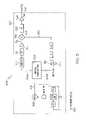
- FIG. 1is block diagram of a conventional frequency synthesizer 100 .
- the frequency synthesizer 100employs a divide by eight frequency divider 102 and a down-converting mixer 104 .
- the divide by eight frequency divider 102 and the down-converting mixer 104converts a signal 106 from a voltage controlled oscillator 108 (VCO) to an intermediate frequency (IF) signal 110 centered on 250 MHz for phase comparison with a variable frequency reference signal 112 generated by a DDS 114 section of a frequency synthesizer integrated circuit 116 such as an AD9858 frequency synthesizer integrated circuit available from Analog Devices, Inc.
- An on-chip digital phase/frequency detector 118is employed for acquisition and an auxiliary analog phase detector 120 is employed to improve phase noise performance.
- the performance of the conventional frequency synthesizer 100is limited as follows. First, the phase comparison is performed using the variable frequency reference signal 112 generated directly by the DDS 114 clocked at 1 GHz.
- the spurious free dynamic range (SFDR) of the DDS 114is approximately ⁇ 50 dBc when it is used to generate a signal at a large fraction of the clock frequency, approximately one quarter in this case. This gives rise to troublesome spurious output signals.
- SFDRspurious free dynamic range
- dBcindicates the relative dB levels of noise or sideband peak power, compared to the carrier power.
- a first unwanted IF signal at 250 MHzwill be generated when the output 122 of the synthesizer 100 is at 11 GHz because:
- the frequency synthesizer 100may be operated only over the frequency range of: 11 GHz>F OUT >6 GHz (3)
- a frequency synthesizercomprises an input terminal and an output terminal, a loop filter, a digital phase detector, and an analog phase detector.
- the digital phase detectorcomprises a first input coupled to the input terminal, a second input coupled to the output terminal, and an output coupled to the loop filter.
- the digital phase detectoris configured to operate at a first phase comparison frequency.
- the analog phase detectorcomprises a first input coupled to the input terminal, a second input coupled to the output terminal, and an output that is alternating current (AC) coupled to the loop filter.
- the analog phase detectoris configured to operate at a second phase comparison frequency.
- the first phase comparison frequencyis different from the second phase comparison frequency.
- FIG. 1is block diagram of a conventional frequency synthesizer.
- FIG. 2is a block diagram of one embodiment of a frequency synthesizer.
- FIG. 3is a schematic diagram of one embodiment of a current to differential voltage converter.
- FIG. 4is a schematic diagram of one embodiment of an analog phase detector comprising a Gilbert cell multiplier circuit.
- FIG. 5is a block diagram of one embodiment of a reference input signal frequency generator.
- FIG. 6is a spectral graph showing the phase noise performance of one embodiment of the frequency synthesizer shown in FIG. 2 .
- FIG. 7is a spectral graph showing the phase noise performance of a conventional frequency synthesizer.
- FIG. 8is a flow diagram.
- the embodiments described hereinare directed to a frequency synthesizer and more particularly to a system and method of reducing phase noise in microwave frequency synthesizers employing a compound phase locked loop comprising a digital phase/frequency detector and an analog phase detector.
- Analog phase detectorsexhibit lower noise floors than digital devices. Analog phase detectors, however, are not able to sense frequency and therefore may be unable to acquire phase lock without the aid of some form of “aided acquisition” circuitry.
- an analog phase detector and a digital phase detectormay be configured to operate at different frequencies and the output of the analog phase detector is alternating current (AC) coupled into a loop filter.
- the digital phase/frequency detectormay facilitate acquisition of phase lock and may set a suitable phase relationship for the signals applied to the analog phase detector.
- the frequency synthesizermay comprise a DDS tracking PLL frequency synthesizer comprising a “compound PLL.”
- the tuning bandwidth of the frequency synthesizermay be limited only by the performance of its components.
- the frequency synthesizermay be realized as a single integrated circuit.
- the frequency synthesizermay comprise a microwave frequency synthesizer comprising a compound PLL.
- the compound PLLmay comprise a digital and an analog phase detector configured to operate at different phase comparison frequencies.
- the analog phase detectormay be employed to detect residual phase noise due to the digital phase detector and frequency divider.
- the detected phase noise voltagemay be AC coupled at a loop filter input node where it is destructively coupled (e.g., combined or summed) with residual noise voltage from the digital phase detector.
- the destructive coupling of the detected phase noise voltage and the residual noise voltageimprove the overall phase noise characteristics of the frequency synthesizer to improve its overall performance.
- the embodimentsare not limited in this context.
- the frequency synthesizermay comprise a digital phase/frequency detector with substantially identical frequency dividers.
- the substantially identical frequency dividersset the phase relationship of the signals at the inputs to the dividers to be in phase. This technique may facilitate the generation of phase quadrature signals to be fed to an analog phase detector.
- the embodimentsare not limited in this context.
- the output signal of the digital phase/frequency detector and the output signal of the analog phase detectormay be AC coupled such that the effects of voltage offset and direct current (DC) drift in the analog phase detector may be substantially or totally negated. As discussed above, this may be accomplished by destructively coupling these output signals at a node.
- the nodemay comprise an input node of a loop filter. The embodiments are not limited in this context.
- FIG. 2is a block diagram of one embodiment of a frequency synthesizer 200 .
- one embodiment of the frequency synthesizer 200comprises a phase locked loop 202 .
- the phase locked loop 202comprises a voltage controlled oscillator (VCO) 204 , a frequency multiplier chain 206 , a programmable digital phase comparator module 208 , an analog phase detector 210 , a loop filter 212 , and a current to differential voltage converter 214 .
- the VCO 204produces an output signal that is fed to the frequency multiplier chain 206 .
- An output signal 248 (F out ) of the frequency synthesizer 200is generated by the VCO 204 and the frequency multiplier chain 206 .
- a sample of the output signalis fed back to the programmable digital phase comparator module 208 .
- the current to differential voltage converter 214converts the output signal of the programmable digital phase comparator module 208 to a differential signal that is fed to an input node at of the loop filter 212 where it is combined with the output signal of the analog phase detector 210 as described below.
- the embodiments, however,are not limited in the context in which they are described herein with reference to FIG. 2 .
- the programmable digital phase comparator module 208comprises a programmable integer divider 216 , an in phase power splitter 218 , a first PLL frequency synthesizer 220 , a second PLL frequency synthesizer 222 , and a quadrature power splitter 224 .
- the programmable integer divider 216receives a feedback signal 226 , which is a sample of output signal 266 of the frequency multiplier chain 206 . It will be appreciated by those skilled in the art that the frequency synthesizer output signal 248 may be a buffered, amplified, or attenuated version of the output signal 266 .
- the programmable integer divider 216may be programmed via programming inputs 228 .
- the programming inputs 228may receive a digital signal comprising an n-bit parallel word, where n is any integer, for example.
- the in phase power splitter 218may comprise a resistor network.
- the in phase power splitter 218may comprise a three-resistor network.
- the first PLL frequency synthesizer 220comprises an N divider 230 , an R divider 232 , and a first digital phase/frequency detector 234 .
- the first PLL frequency synthesizer 220may be programmed via programming input 236 .
- the programming input 236may be configured to receive a digital signal comprising an a-bit serial word, where a is any integer, for example.
- the R divider 232is set to 1 and the N divider 230 is programmable via the programming input 236 .
- the second PLL frequency synthesizer 222comprises an N divider 238 , an R divider 242 , and a second digital phase/frequency detector 240 .
- the second PLL frequency synthesizer 222may be programmed via programming input 244 .
- the programming input 244may be configured to receive a digital signal comprising an a-bit serial word, where a is any integer, for example.
- the R divider 242 and the digital phase/frequency detector 240are not used and the N divider 238 is programmable via the programming input 244 .
- first and second PLL frequency synthesizers 220 , 222comprise substantially identical components. It may be preferable to employ PLL frequency synthesizers 220 , 222 with substantially identical components to improve the overall phase noise performance of the frequency synthesizer 200 .
- the first and second digital phase/frequency detectors 234 , 240each may be formed as portions of a separate ADF4106 PLL frequency synthesizer integrated circuit available from Analog Devices, Inc.
- the microwave frequency output signal 248 (F out )is generated by the VCO 204 and the frequency multiplier chain 206 .
- the VCO 204may generate a 2.5 GHz signal 264 to drive a ⁇ 4 frequency multiplier chain 206 where the VCO output signal 264 is multiplied by a factor of four to produce the output signal 266 .
- the frequency multiplier chain 206comprises multiple buffers 256 , two ⁇ 2 multipliers 258 , and a band pass filter 260 operatively coupled to multiply and buffer the VCO 204 output signal 264 to generate the output signal 266 at a frequency of 10 GHz.
- the output signal 266may be buffered by output buffer 262 to generate the frequency output signal 248 (F out ) at an output port or terminal of the frequency synthesizer 200 , for example.
- a sample of the output signal 266is fed to a high frequency programmable integer divider 216 circuit.
- a suitable high frequency programmable integer divider 216is a UXN14M9P available from Centellax.
- the division ratio of the high frequency programmable integer divider 216 devicemay be set to a number M such that the frequency of the output signal 268 of the programmable integer divider 216 is within a suitable range for downstream components or elements.
- the high frequency programmable integer divider 216 devicemay be programmed via programming inputs 228 to any integer number M.
- the frequency of the output signal 268may be in the ultra-high frequency (UHF) range.
- UHFultra-high frequency
- a reference input signal 246 (F ref ) of a suitable frequencymay be generated by a reference input signal generator 247 .
- the output signal 268 of the programmable integer divider 216is split into two paths by the in-phase power splitter 218 .
- the first pathfeeds a first output signal 250 to the first PLL frequency synthesizer 220 .
- the first frequency synthesizer 220may be an ADF4106 PLL frequency synthesizer integrated circuit available from Analog Devices.
- the division ratio of the N divider 230 of the first frequency divider 220may be set via programming input 236 to set the frequency (F comp ) of the first input signal 250 within a suitable operating range of the first phase/frequency detector 234 .
- a phase difference signal current 251is generated by the first digital phase/frequency detector 234 of the first PLL frequency synthesizer 220 .
- the phase difference signal current 251may be fed to a current to differential voltage converter 214 circuit.
- the current to differential voltage converter 214 circuitproduces a differential phase difference voltage signal 252 (V A ⁇ V B ) between output terminals 252 a and 252 b .
- the differential phase difference voltage signal 252 (V A ⁇ V B )is fed to the differential input node of a differential input loop filter 212 .
- the differential input loop filter 212may comprise an, active, low-pass filter, for example.
- the PLL 202acquires phase lock when power is applied to frequency synthesizer 200 when the signal 270 at the output port of the N divider 238 is in phase with the signal 272 at the output of the N divider 230 .
- the output signals 270 , 272are generally in phase relative to each other because the phase/frequency detector 234 automatically locks to this condition.
- the signals 250 and 248 at the inputs of the respective first N divider 230 and the second N divider 238also are in phase because the dividers are substantially identical, especially if they are formed as a single integrated circuit or as separate integrated circuit using the same semiconductor process.
- a second output signal 255is fed from the in-phase power splitter 218 to an input of the analog phase detector 210 .
- a second input signal 253is fed to a second input of the analog phase detector 210 .
- the second input signal 253is a fundamental frequency signal, with no frequency division, derived from the reference input signal 246 .
- the frequency of the second input signal 253 to the analog phase detector 210is 555.55555556 MHz.
- the second input signal 253may be derived from the quadrature power splitter 224 and is in quadrature with the reference input signal 246 .
- the analog phase detector 210may comprise a Gilbert cell circuit.
- One example of a Gilbert cellincludes a HFA3101 Gilbert cell transistor array available from Intersil.
- the two input signals 253 , 255 to the analog phase detector 210are in phase quadrature relative to each other when the PLL 202 is held in lock by the first digital phase/frequency detector 234 .
- the mean differential DC output voltage signal of the analog phase detector 210may be substantially zero in this condition.
- the analog phase detector 210produces a differential alternating output noise voltage 254 between terminals 254 a and 254 b corresponding to the residual phase noise of the digital phase/frequency detector 234 and the respective first and second N dividers 230 , 238 .
- the differential alternating output noise voltage 254 signalis AC coupled into the differential input node of the active low-pass loop filter 212 in any suitable manner such that it is destructively combined or summed with the residual noise voltage 252 from the current to differential voltage converter 214 .
- the residual noise voltage 252is proportional to the noise current of the digital phase/frequency detector 234 .
- the destructive coupling of the differential alternating output noise voltage 254 and the residual noise voltage 252substantially reduces the amplitude of the noise sidebands of the output signal 248 (F out ).
- FIG. 3is a schematic diagram of one embodiment of a current to differential voltage converter 300 .
- the current to differential voltage converter 300is similar to the current to differential voltage converter 214 employed in the frequency synthesizer 200 illustrated in FIG. 2 .
- the current to differential voltage converter 214comprises first and second amplifiers A 1 , A 2 , a resistor network 302 comprising resistors R, and a feedback resistor R F .
- the input current signal 251 (I IN ) from the digital phase/frequency detector 234is applied through the feedback resistor R F to the output of the second amplifier A 2 .
- a reference voltage signal V refis applied to a positive input terminal of the second amplifier A 2 .
- the resistor network 302may be operatively coupled to the first and second amplifiers A 1 , A 2 to generate a differential output voltage 252 between terminals 252 a and 252 b .
- FIG. 4is a schematic diagram of one embodiment of an analog phase detector 400 comprising a Gilbert cell multiplier circuit.
- the Gilbert cell multiplier circuit analog phase detector 400is similar to the analog phase detector 210 employed in the frequency synthesizer 200 illustrated in FIG. 2 .
- the analog phase detector 210comprises transistors Q 1 -Q 6 arranged to form a Gilbert multiplier cell connected between V CC and V EE .
- the inputs to the analog phase detector 214are denoted as ⁇ i and ⁇ o and the output of the analog phase detector 210 is denoted as ⁇ d .
- the first input signal 255 to the analog phase detector 210may be denoted as ⁇ o and the second input signal 253 to the analog phase detector 210 may be denoted as ⁇ i , for example.
- the output of the analog phase detector 210may be denoted as first input signal 255 fed to the analog phase detector 210 as ⁇ d , for example.
- the embodiments, however,are not limited in the context in which they are described herein with reference to FIG. 4 .
- FIG. 5is a block diagram of one embodiment of a reference input signal frequency generator 500 .
- the reference input signal frequency generator 500is similar to the reference input signal frequency generator 247 employed in the frequency synthesizer 200 illustrated in FIG. 2 .
- the reference input signal frequency generator 247is a UHF reference signal generator.
- a voltage controlled, surface acoustic wave resonator oscillator 502 (VCSO)is phase locked to an input reference signal 504 at an input frequency f in .
- the input reference signal 502may be (usually) derived from an oven controlled crystal oscillator (OCXO), for example.
- OXOoven controlled crystal oscillator
- the phase locked SAW VCSO oscillator 502produces a very stable, low phase noise oscillator signal 506 which is fed to an in-phase power splitter 508 .
- the signal 506has a frequency of 1000 MHz (or 1 GHz).
- a first half of the oscillator signal 506 ais fed to a high speed divide by two circuit 510 and low-pass filter 512 to produce a sinusoidal voltage signal 514 .
- the sinusoidal voltage signal 512is at a frequency of 500 MHz.
- the sinusoidal voltage signal 512is amplified and used to provide a local oscillator drive f LO to an up-conversion mixer 516 .
- a second half of the oscillator signal 506 b signalis used to clock a direct digital synthesizer 518 (DDS) device.
- the DDS 518may be an AD9912 available from Analog Devices.
- the DDS 518may be programmed via programming inputs 520 to generate signals in a first frequency range, which are fed to the IF input 522 of the up-conversion mixer 516 .
- the first frequency rangeis 45 to 75 MHz.
- the DDS 518may comprise a 48-bit Accumulator section giving the device a frequency resolution (minimum step size) of:
- the output signal 524 from the mixer 516is filtered by band pass filter 526 and amplified by amplifier 528 .
- the output signal 524 from the mixer 516may be programmed to any frequency.
- the output signal 524 from the mixer 516may be programmed to any frequency between 545 and 575 MHz in steps of 3.55 ⁇ 10 ⁇ 6 Hz, for example.
- the geometric center frequency (F center ) of the reference signal 246 (F ref ) of the reference generator 247is approximately 560 MHz.
- the microwave frequency synthesizer 200may be programmed as follows:
- the DDS 518is programmed to generate a signal at a frequency of 55.5555555555 MHz.
- F out min4360 MHz
- FIG. 6is a spectral graph 600 showing the phase noise performance of one embodiment of the frequency synthesizer 200 shown in FIG. 2 .
- FIG. 7is a spectral graph 700 showing the phase noise performance of a conventional frequency synthesizer.
- the spectral graph 600represents the ratio of power in the side bands 602 a, b relative to the carrier power 604 .
- the spectral graph 700represents the ratio of power in the side bands 702 a, b relative to the carrier power 704 .
- the vertical scale for both spectral plots 600 , 700is 10 dB/div and the horizontal scale is 5 kHz/div. From FIG. 6 it can be seen that the carrier power 604 , 704 is centered on 7.42 GHz.
- the spectral graph 600 of the frequency synthesizer 200shows improved phase noise performance over the spectral graph 700 of the conventional frequency synthesizer.
- the spectral graph 600 of the frequency synthesizer 200shows a 20 bB improvement in phase noise performance over the spectral graph 700 of the conventional frequency synthesizer.
- FIG. 8is a flow diagram 800 .
- the flow diagram 800may be representative of the operations or functions executed by one or more elements or components of the frequency synthesizers described herein, such as the frequency synthesizer 200 , for example.
- the programmable digital phase comparator module 208receives 802 the feedback signal 226 portion of the output signal 248 of the frequency synthesizer 200 having a first frequency.
- the programmable digital phase comparator module 208receives 804 an input signal 246 to the frequency synthesizer having a second frequency.
- the PLL frequency synthesizer 220 of the programmable digital phase comparator module 208produces 806 a first phase difference signal 251 based on the phase difference between the input signal 246 and the output signal 248 .
- the current to differential voltage converter 214generates a differential phase difference signal 252 from the first phase difference signal 251 .
- the analog phase detector 210produces 808 a second phase difference signal 254 based on an analog phase difference between the input signal 246 and the output signal 248 .
- the differential phase difference signal 252is applied to a differential input node of the loop filter 212 .
- the differential phase difference signal 252 derived from the first phase difference signal 251is DC coupled to the loop filter 212 .
- the second phase difference signal 254is AC coupled to the loop filter 212 .
- the second phase difference signal 254is destructively coupled 810 with the differential phase difference signal 252 derived from the first phase difference signal 251 .
- the in phase splitter 218splits the feedback signal 226 into a first signal 255 and a second signal 250 , wherein the first and second signals 255 , 250 are in in-phase relationship.
- the quadrature phase splitter 224splits the input signal 246 into a third signal 253 and a fourth signal 248 .
- the third and fourth signals 253 , 248are in quadrature-phase relationship.
- the PLL frequency synthesizer 220produces the first phase difference signal 251 by detecting the difference between the fourth signal 248 and the second signal 250 and the first digital phase/frequency detector 234 locks at a relatively lower phase comparison frequency relative to the phase comparison frequency of the analog phase detector 210 .
- the analog phase detector 210produces the second phase difference signal 254 by detecting the phase difference between the third signal 253 and the first signal 255 .
- the analog phase detector 210reduces the phase noise because it operates at a much higher phase comparison frequency relative to the first digital phase/frequency detector 234 .
- the programmable integer divider 216divides the first frequency of the feedback signal 226 by a first integer.
- the second PLL frequency synthesizer 222divides the second frequency of the input signal 246 by a second integer.
- any reference to “one embodiment” or “an embodiment”means that a particular feature, structure, or characteristic described in connection with the embodiment is included in at least one embodiment.
- the appearances of the phrase “in one embodiment” in various places in the specificationare not necessarily all referring to the same embodiment.
- Some embodiments of the frequency synthesizer 200 and any processing module thereofmay be implemented using an architecture that may vary in accordance with any number of factors, such as desired computational rate, power levels, heat tolerances, processing cycle budget, input data rates, output data rates, memory resources, data bus speeds and other performance constraints.
- an embodimentmay be implemented using software executed by a general-purpose or special-purpose processor.
- an embodimentmay be implemented as dedicated hardware, such as a circuit, an application specific integrated circuit (ASIC), Programmable Logic Device (PLD) or digital signal processor (DSP), and so forth.
- ASICapplication specific integrated circuit
- PLDProgrammable Logic Device
- DSPdigital signal processor
- an embodimentmay be implemented by any combination of programmed general-purpose computer components and custom hardware components. The embodiments are not limited in this context.
- Coupledand “connected” along with their derivatives. It should be understood that these terms are not intended as synonyms for each other. For example, some embodiments may be described using the term “connected” to indicate that two or more elements are in direct physical or electrical contact with each other. In another example, some embodiments may be described using the term “coupled” to indicate that two or more elements are in direct physical or electrical contact. The term “coupled,” however, may also mean that two or more elements are not in direct contact with each other, but yet still co-operate or interact with each other. The embodiments are not limited in this context.
- the frequency synthesizer 200may be illustrated and described as comprising several separate functional elements, such as modules and/or blocks. Although certain modules and/or blocks may be described by way of example, it can be appreciated that a greater or lesser number of modules and/or blocks may be used and still fall within the scope of the embodiments. Further, although various embodiments may be described in terms of modules and/or blocks to facilitate description, such modules and/or blocks may be implemented by one or more hardware components (e.g., processors, DSPs, PLDs, ASICs, circuits, registers), software components (e.g., programs, subroutines, logic) and/or combination thereof.
- hardware componentse.g., processors, DSPs, PLDs, ASICs, circuits, registers
- software componentse.g., programs, subroutines, logic
- the modulesmay comprise, or be implemented as, one or more systems, sub-systems, devices, components, circuits, logic, programs, or any combination thereof, as desired for a given set of design or performance constraints.
- the modulesmay comprise electronic elements fabricated on a substrate.
- the electronic elementsmay be fabricated using silicon-based IC processes such as high-speed complementary metal oxide semiconductor (CMOS), bipolar, high-speed bipolar CMOS (BiCMOS) processes, for example, as well as Gallium Arsenide (GaAs), Indium Phosphide (InP), and/or Indium Arsenide heterojunction (InAs) bipolar transistors (HBT).
- CMOScomplementary metal oxide semiconductor
- BiCMOSbipolar, high-speed bipolar CMOS
- GaAsGallium Arsenide
- InAsIndium Arsenide heterojunction bipolar transistors
- processingrefers to the action and/or processes of a computer or computing system, or similar electronic computing device, that manipulates and/or transforms data represented as physical quantities (e.g., electronic) within the registers and/or memories of the computing system into other data similarly represented as physical quantities within the memories, registers or other such information storage, transmission or display devices of the computing system.
- physical quantitiese.g., electronic
- the embodimentsare not limited in this context.
Landscapes
- Stabilization Of Oscillater, Synchronisation, Frequency Synthesizers (AREA)
Abstract
Description
11 GHz>FOUT>6 GHz (3)
(VA−VB)=2*IIN*RF (4)
Claims (22)
Priority Applications (1)
| Application Number | Priority Date | Filing Date | Title |
|---|---|---|---|
| US11/803,602US7656236B2 (en) | 2007-05-15 | 2007-05-15 | Noise canceling technique for frequency synthesizer |
Applications Claiming Priority (1)
| Application Number | Priority Date | Filing Date | Title |
|---|---|---|---|
| US11/803,602US7656236B2 (en) | 2007-05-15 | 2007-05-15 | Noise canceling technique for frequency synthesizer |
Publications (2)
| Publication Number | Publication Date |
|---|---|
| US20080284525A1 US20080284525A1 (en) | 2008-11-20 |
| US7656236B2true US7656236B2 (en) | 2010-02-02 |
Family
ID=40026920
Family Applications (1)
| Application Number | Title | Priority Date | Filing Date |
|---|---|---|---|
| US11/803,602Active2027-12-20US7656236B2 (en) | 2007-05-15 | 2007-05-15 | Noise canceling technique for frequency synthesizer |
Country Status (1)
| Country | Link |
|---|---|
| US (1) | US7656236B2 (en) |
Cited By (10)
| Publication number | Priority date | Publication date | Assignee | Title |
|---|---|---|---|---|
| US20080218217A1 (en)* | 2007-03-07 | 2008-09-11 | Hitachi, Ltd. | Semiconductor integrated circuit device |
| US20140022830A1 (en)* | 2012-02-17 | 2014-01-23 | Huawei Technologies Co., Ltd. | Frequency multiplier and method for generating frequency multiplied signals |
| US20160373117A1 (en)* | 2015-06-18 | 2016-12-22 | Yekutiel Josefsberg | Ultra low phase noise frequency synthesizer |
| US10141943B1 (en)* | 2018-02-21 | 2018-11-27 | Teledyne Defense Electronics, Llc | High speed acquisition system for phase locked loops |
| US10205457B1 (en) | 2018-06-01 | 2019-02-12 | Yekutiel Josefsberg | RADAR target detection system for autonomous vehicles with ultra lowphase noise frequency synthesizer |
| US10404261B1 (en) | 2018-06-01 | 2019-09-03 | Yekutiel Josefsberg | Radar target detection system for autonomous vehicles with ultra low phase noise frequency synthesizer |
| US20190346877A1 (en)* | 2018-05-11 | 2019-11-14 | Analog Devices Global Unlimited Company | Apparatus and methods for timing offset compensation in frequency synthesizers |
| US10598764B2 (en)* | 2017-10-30 | 2020-03-24 | Yekutiel Josefsberg | Radar target detection and imaging system for autonomous vehicles with ultra-low phase noise frequency synthesizer |
| US10686455B1 (en) | 2019-08-14 | 2020-06-16 | Teledyne Defense Electronics, Llc | Digital high speed acquisition system for phase locked loops |
| US11483920B2 (en)* | 2019-12-13 | 2022-10-25 | Jefferson Science Associates, Llc | High efficiency normal conducting linac for environmental water remediation |
Families Citing this family (9)
| Publication number | Priority date | Publication date | Assignee | Title |
|---|---|---|---|---|
| KR101264770B1 (en)* | 2009-11-16 | 2013-05-15 | 한국전자통신연구원 | Phase locked loop apparatus and thereof for terminal in satellite communication |
| US9356611B1 (en) | 2009-12-30 | 2016-05-31 | Gsi Technology, Inc. | Systems and methods involving phase detection with adaptive locking/detection features |
| US8638144B1 (en) | 2009-12-30 | 2014-01-28 | Gsi Technology, Inc. | Systems and methods involving phase detection with adaptive locking/detection features |
| US10718804B2 (en) | 2012-01-31 | 2020-07-21 | Keysight Technologies, Inc. | System for measuring residual phase noise |
| US9356769B2 (en) | 2014-09-24 | 2016-05-31 | Qualcomm Incorporated | Synchronous reset and phase detecting for interchain local oscillator (LO) divider phase alignment |
| US9356768B2 (en)* | 2014-09-24 | 2016-05-31 | Qualcomm Incorporated | Phase detecting circuit for interchain local oscillator (LO) divider phase alignment |
| US10523254B2 (en)* | 2017-07-20 | 2019-12-31 | Qualcomm Incorporated | Mixer S11 control via sum component termination |
| CN110166048B (en)* | 2019-07-01 | 2024-09-06 | 无锡华测电子系统有限公司 | Novel ultra-wideband low-phase noise frequency source |
| US12218671B2 (en) | 2021-02-24 | 2025-02-04 | Rohde & Schwarz Gmbh & Co. Kg | Phase coherent synthesizer |
Citations (330)
| Publication number | Priority date | Publication date | Assignee | Title |
|---|---|---|---|---|
| US2111412A (en) | 1928-12-08 | 1938-03-15 | Gen Electric | X-ray apparatus |
| CH260999A (en) | 1939-05-13 | 1949-04-15 | Standard Telephon & Radio Ag | Method for the linear amplification of an amplitude-modulated wave and amplifier system for carrying out the method. |
| US2493606A (en) | 1945-06-11 | 1950-01-03 | Gen Electric | X-ray apparatus |
| US2706366A (en) | 1950-11-25 | 1955-04-19 | Bell Telephone Labor Inc | Method of constructing a helix assembly |
| US2718622A (en) | 1953-03-16 | 1955-09-20 | Bell Telephone Labor Inc | Attenuation equalizer |
| GB760555A (en) | 1953-11-04 | 1956-10-31 | Philips Electrical Ind Ltd | Improvements in or relating to equalizing networks |
| DE965048C (en) | 1954-05-25 | 1957-05-29 | Deutsche Bundespost | Arrangement for linearizing the amplitude characteristic of the traveling wave tubes in an amplifier circuit |
| US2939952A (en) | 1953-12-24 | 1960-06-07 | Paul | Apparatus for separating charged particles of different specific charges |
| US2950389A (en) | 1957-12-27 | 1960-08-23 | Siemens Ag | Method of separating ions of different specific charges |
| US3065640A (en) | 1959-08-27 | 1962-11-27 | Thompson Ramo Wooldridge Inc | Containment device |
| US3119969A (en) | 1960-09-22 | 1964-01-28 | Philips Corp | Means for linearizing the amplitude characteristic curves of power amplifiers |
| GB984607A (en) | 1962-07-19 | 1965-02-24 | Ferranti Ltd | Improvements relating to travelling-wave tubes |
| US3260875A (en) | 1963-08-30 | 1966-07-12 | Allis Chalmers Mfg Co | Dynamoelectric machine core and method of making same |
| US3300677A (en) | 1962-03-30 | 1967-01-24 | Rca Corp | Electrode mount and method of manufacture thereof |
| US3310864A (en) | 1963-05-01 | 1967-03-28 | Huggins Lab Inc | Method of making a traveling wave guide device |
| US3334225A (en) | 1964-04-24 | 1967-08-01 | California Inst Res Found | Quadrupole mass filter with means to generate a noise spectrum exclusive of the resonant frequency of the desired ions to deflect stable ions |
| US3423638A (en) | 1964-09-02 | 1969-01-21 | Gti Corp | Micromodular package with compression means holding contacts engaged |
| US3453711A (en) | 1966-08-24 | 1969-07-08 | Corning Glass Works | Method of connecting together a plurality of transducer segments |
| US3541467A (en) | 1969-04-25 | 1970-11-17 | Bell Telephone Labor Inc | Feed-forward amplifier with frequency shaping |
| US3546511A (en) | 1967-07-31 | 1970-12-08 | Rigaku Denki Co Ltd | Cooling system for a rotating anode of an x-ray tube |
| US3564124A (en) | 1968-04-10 | 1971-02-16 | Chroma Gain Control | Chroma-gain control and color killer circuits |
| US3612880A (en) | 1968-12-23 | 1971-10-12 | Alain Lansiart | Method of spark control and systems for the utilization of said method in spark chambers |
| US3617740A (en) | 1968-10-08 | 1971-11-02 | High Voltage Engineering Corp | Modular electron source for uniformly irradiating the surface of a product |
| US3624678A (en) | 1966-09-15 | 1971-11-30 | Hughes Aircraft Co | Method for making dielectric-to-metal joints for slow-wave structure assemblies |
| US3688222A (en) | 1971-03-18 | 1972-08-29 | Us Army | Matched ultrasonic delay line with solderable transducer electrodes |
| US3696324A (en) | 1970-10-19 | 1972-10-03 | Gilbert Baum | Electrical display systems |
| US3716745A (en) | 1971-07-22 | 1973-02-13 | Litton Systems Inc | Double octave broadband traveling wave tube |
| US3748729A (en) | 1972-03-07 | 1973-07-31 | Sperry Rand Corp | Traveling wave tube interaction circuit manufacture |
| US3753140A (en) | 1970-09-09 | 1973-08-14 | Wandel & Goltermann | Equalizing network |
| US3755717A (en) | 1971-05-14 | 1973-08-28 | Lucas Industries Ltd | Wiring arrangement |
| US3780334A (en) | 1971-06-09 | 1973-12-18 | Thomson Csf | Vacuum tube for generating a wide beam of fast electrons |
| US3796965A (en) | 1971-12-28 | 1974-03-12 | Westinghouse Electric Corp | Voltage droop compensation circuit for traveling wave tubes |
| US3873889A (en) | 1973-08-08 | 1975-03-25 | Sperry Rand Corp | Indicator module and method of manufacturing same |
| US3886470A (en) | 1973-12-04 | 1975-05-27 | Amplifier Design And Service I | Feed-forward amplifier system |
| US3893048A (en) | 1974-07-08 | 1975-07-01 | Us Army | Matched MIC delay line transducer using a series array |
| US3900823A (en) | 1973-03-28 | 1975-08-19 | Nathan O Sokal | Amplifying and processing apparatus for modulated carrier signals |
| US3946341A (en) | 1975-01-06 | 1976-03-23 | Lignes Telegraph Telephon | Broadband electroacoustic delay lines |
| US3955161A (en) | 1974-08-05 | 1976-05-04 | General Dynamics Corporation | Molded waveguide filter with integral tuning posts |
| US3956712A (en) | 1973-02-05 | 1976-05-11 | Northrop Corporation | Area electron gun |
| US4000471A (en) | 1975-10-14 | 1976-12-28 | The United States Of America As Represented By The Secretary Of The Navy | TWT grid circuit utilizing feedback |
| US4004253A (en) | 1974-06-21 | 1977-01-18 | Hitachi, Ltd. | Variable equalizer |
| US4016515A (en) | 1975-12-31 | 1977-04-05 | Hughes Aircraft Company | Bulk acoustic wave delay line |
| US4034319A (en) | 1976-05-10 | 1977-07-05 | Trw Inc. | Coupled bar microwave bandpass filter |
| US4035747A (en) | 1974-01-29 | 1977-07-12 | Wilhelm Ruf Kg | Adjustable attenuation equalizer |
| US4037182A (en) | 1976-09-03 | 1977-07-19 | Hughes Aircraft Company | Microwave tuning device |
| US4053855A (en) | 1975-10-28 | 1977-10-11 | International Telephone And Telegraph Corporation | Method and arrangement to eliminate multipacting in RF devices |
| US4059815A (en) | 1975-07-31 | 1977-11-22 | Matsushita Electric Industrial Co., Limited | Coaxial cavity resonator |
| US4061944A (en) | 1975-06-25 | 1977-12-06 | Avco Everett Research Laboratory, Inc. | Electron beam window structure for broad area electron beam generators |
| GB1507458A (en) | 1975-10-30 | 1978-04-12 | Gen Electric Co Ltd | Bulk acoustic wave devices |
| US4100450A (en) | 1977-02-17 | 1978-07-11 | Energy Sciences Inc. | Method of and apparatus for generating longitudinal strips of energetic electron beams |
| GB1519456A (en) | 1975-09-18 | 1978-07-26 | Post Office | Wideband amplifier arrangement |
| US4126370A (en) | 1977-06-17 | 1978-11-21 | Bunker Ramo Corporation | Filter connector with radial mounting means |
| US4134114A (en) | 1977-04-14 | 1979-01-09 | Hughes Aircraft Company | Radar system having amplitude and phase modulation and demodulation circuits |
| US4165472A (en) | 1978-05-12 | 1979-08-21 | Rockwell International Corporation | Rotating anode x-ray source and cooling technique therefor |
| US4184123A (en) | 1977-09-19 | 1980-01-15 | Rca Corporation | Double-tuned output circuit for high power devices using coaxial cavity resonators |
| US4197540A (en) | 1977-04-27 | 1980-04-08 | Hughes Aircraft Company | Simultaneous transmit and receive radar subsystem |
| US4216448A (en) | 1977-01-21 | 1980-08-05 | Nippon Electric Co., Ltd. | Microwave distributed-constant band-pass filter comprising projections adjacent on capacitively coupled resonator rods to open ends thereof |
| US4233539A (en) | 1979-03-05 | 1980-11-11 | Varian Associates, Inc. | Electron tube with reduced secondary emission |
| US4258328A (en) | 1978-03-03 | 1981-03-24 | Societe Lignes Telegraphiques Et Telephoniques | Feed forward microwave amplifier for communication systems |
| US4267516A (en) | 1979-08-03 | 1981-05-12 | Tektronix, Inc. | Common-emitter fT doubler amplifier employing a feed forward amplifier to reduce non-linearities and thermal distortion |
| US4270069A (en) | 1978-08-03 | 1981-05-26 | Siemens Aktiengesellschaft | Traveling wave tube and method of making same |
| US4276514A (en) | 1979-07-09 | 1981-06-30 | Trw Inc. | Wideband, phase compensated amplifier with negative feedback of distortion components in the output signal |
| US4278957A (en) | 1979-07-16 | 1981-07-14 | Motorola, Inc. | UHF Filter assembly |
| US4292610A (en) | 1979-01-26 | 1981-09-29 | Matsushita Electric Industrial Co., Ltd. | Temperature compensated coaxial resonator having inner, outer and intermediate conductors |
| US4304978A (en) | 1978-10-05 | 1981-12-08 | Coherent, Inc. | Heat treating using a laser |
| US4309677A (en) | 1980-05-05 | 1982-01-05 | Alpha Industries, Inc. | Microstrip "T" type attenuator network |
| GB2018171B (en) | 1978-03-29 | 1982-05-06 | Heidenhain Gmbh Dr Johannes | Adjustable table device |
| US4359666A (en) | 1980-07-21 | 1982-11-16 | Varian Associates, Inc. | Cylindrical cathode with segmented electron emissive surface and method of manufacture |
| US4374394A (en) | 1980-10-01 | 1983-02-15 | Rca Corporation | Monolithic integrated circuit |
| US4376927A (en) | 1978-12-18 | 1983-03-15 | Mcgalliard James D | Printed circuit fuse assembly |
| US4379741A (en) | 1980-07-11 | 1983-04-12 | Nippondenso Co., Ltd. | Oxygen concentration sensor |
| US4382238A (en) | 1979-11-30 | 1983-05-03 | Matsushita Electric Industrial Company, Limited | Band stop filter and circuit arrangement for common antenna |
| US4406770A (en) | 1981-02-03 | 1983-09-27 | Coal Industry (Patents) Limited | Gas sensor |
| US4412272A (en) | 1981-08-31 | 1983-10-25 | General Dynamics, Pomona Division | Flexible printed circuit card assembly |
| US4431977A (en) | 1982-02-16 | 1984-02-14 | Motorola, Inc. | Ceramic bandpass filter |
| US4446445A (en) | 1982-11-24 | 1984-05-01 | Rockwell International Corporation | Singly terminated push-pull distributed amplifier |
| US4455504A (en) | 1981-04-02 | 1984-06-19 | Iversen Arthur H | Liquid cooled anode x-ray tubes |
| US4488128A (en) | 1983-04-22 | 1984-12-11 | Gte Products Corporation | Bifurcated electroacoustic delay line with diagonal coupling |
| US4495640A (en) | 1982-06-28 | 1985-01-22 | Frey Douglas R | Adjustable distortion guitar amplifier |
| GB2143237A (en) | 1983-07-12 | 1985-02-06 | Raychem Corp | Electrically insulating foamed polymers |
| US4506241A (en) | 1981-12-01 | 1985-03-19 | Matsushita Electric Industrial Co., Ltd. | Coaxial dielectric resonator having different impedance portions and method of manufacturing the same |
| US4510551A (en) | 1984-05-21 | 1985-04-09 | Endeco Canada Limited | Portable memory module |
| EP0148706A2 (en) | 1984-01-10 | 1985-07-17 | Thomson-Csf | Adjustable impedance network and control circuit therefor |
| US4532478A (en) | 1984-05-30 | 1985-07-30 | Rockwell International Corporation | Phase adjusted feedforward system utilizing a single amplitude/phase equalizer |
| US4540954A (en) | 1982-11-24 | 1985-09-10 | Rockwell International Corporation | Singly terminated distributed amplifier |
| US4540884A (en) | 1982-12-29 | 1985-09-10 | Finnigan Corporation | Method of mass analyzing a sample by use of a quadrupole ion trap |
| US4554514A (en) | 1984-12-21 | 1985-11-19 | Rca Corporation | Predistortion circuit with feedback |
| US4577340A (en) | 1983-09-19 | 1986-03-18 | Technicare Corporation | High vacuum rotating anode X-ray tube |
| US4581595A (en) | 1984-05-30 | 1986-04-08 | Rockwell International Corporation | Phase shift network with minimum amplitude ripple |
| US4583049A (en) | 1984-06-15 | 1986-04-15 | Trw Inc. | Feed-forward circuit |
| US4584699A (en) | 1984-01-06 | 1986-04-22 | The Perkin-Elmer Corporation | X-ray anode assembly |
| DE3438382A1 (en) | 1984-10-19 | 1986-04-24 | ANT Nachrichtentechnik GmbH, 7150 Backnang | Device for increasing the multi-carrier output power in a travelling-wave-tube amplifier |
| US4595882A (en) | 1984-05-30 | 1986-06-17 | Rockwell International Corporation | Phase adjusted feedforward error correction |
| US4600892A (en) | 1984-06-28 | 1986-07-15 | Hughes Aircraft Company | RF amplifier with frequency spectrum control |
| US4622687A (en) | 1981-04-02 | 1986-11-11 | Arthur H. Iversen | Liquid cooled anode x-ray tubes |
| US4625533A (en) | 1984-04-11 | 1986-12-02 | Hitachi, Ltd. | Method and apparatus for increasing thickness of tubular member |
| US4629996A (en) | 1983-11-15 | 1986-12-16 | Kokusai Denshin Denwa Co., Ltd. | Feed-forward microwave power amplifier with difference signal distortion cancellation circuit |
| EP0205399A2 (en) | 1985-06-10 | 1986-12-17 | ORBISPHERE CORPORATION Wilmington Succursale de Collonge-Bellerive | Amperometric cell and method |
| US4631506A (en) | 1982-07-15 | 1986-12-23 | Matsushita Electric Industrial Co., Ltd. | Frequency-adjustable coaxial dielectric resonator and filter using the same |
| GB2178540A (en) | 1985-07-25 | 1987-02-11 | Teledyne Ind | Electrochemical gas sensor |
| US4664769A (en) | 1985-10-28 | 1987-05-12 | International Business Machines Corporation | Photoelectric enhanced plasma glow discharge system and method including radiation means |
| US4688239A (en) | 1984-09-24 | 1987-08-18 | The B. F. Goodrich Company | Heat dissipation means for X-ray generating tubes |
| US4701717A (en) | 1985-06-22 | 1987-10-20 | Ant Nachrichtentechnik Gmbh | Operating point-stabilized linearized traveling wave tube amplifier |
| US4728846A (en) | 1985-05-28 | 1988-03-01 | Sony Corporation | Electron gun in which the large diameter portion of the first anode is rigidly supported |
| US4727641A (en) | 1985-06-07 | 1988-03-01 | Kawasaki Jukogyo Kabushiki Kaisha | Thermoplastic method of reducing the diameter of a metal tube |
| US4730173A (en) | 1983-06-23 | 1988-03-08 | Murata Manufacturing Co., Ltd. | Asymmetrical trap comprising coaxial resonators, reactance elements, and transmission line elements |
| US4733208A (en) | 1984-08-21 | 1988-03-22 | Murata Manufacturing Co., Ltd. | Dielectric filter having impedance changing means coupling adjacent resonators |
| US4736101A (en) | 1985-05-24 | 1988-04-05 | Finnigan Corporation | Method of operating ion trap detector in MS/MS mode |
| US4739448A (en) | 1984-06-25 | 1988-04-19 | Magnavox Government And Industrial Electronics Company | Microwave multiport multilayered integrated circuit chip carrier |
| US4740765A (en) | 1985-09-30 | 1988-04-26 | Murata Manufacturing Co., Ltd. | Dielectric filter |
| US4749860A (en) | 1986-06-05 | 1988-06-07 | Finnigan Corporation | Method of isolating a single mass in a quadrupole ion trap |
| US4761545A (en) | 1986-05-23 | 1988-08-02 | The Ohio State University Research Foundation | Tailored excitation for trapped ion mass spectrometry |
| US4771172A (en) | 1987-05-22 | 1988-09-13 | Finnigan Corporation | Method of increasing the dynamic range and sensitivity of a quadrupole ion trap mass spectrometer operating in the chemical ionization mode |
| US4779056A (en) | 1986-12-05 | 1988-10-18 | U.S. Philips Corporation | Active filter |
| US4788705A (en) | 1984-12-20 | 1988-11-29 | Varian Assoicates, Inc. | High-intensity X-ray source |
| EP0293791A1 (en) | 1987-06-02 | 1988-12-07 | IVERSEN, Arthur H. | Liquid cooled rotating anodes |
| US4792879A (en) | 1984-04-17 | 1988-12-20 | I F M Electronic Gmbh | Mounting structure for electric and electronic circuit elements |
| US4818869A (en) | 1987-05-22 | 1989-04-04 | Finnigan Corporation | Method of isolating a single mass or narrow range of masses and/or enhancing the sensitivity of an ion trap mass spectrometer |
| US4828022A (en) | 1980-03-04 | 1989-05-09 | Ford Aerospace & Communications Corporation | Heat conducting sleeve |
| US4841179A (en) | 1986-12-26 | 1989-06-20 | Kabushiki Kaisha Toshiba | Phase equalizing active filter |
| EP0180328B1 (en) | 1984-10-22 | 1989-08-30 | Finnigan Corporation | Method of mass analyzing a sample over a wide mass range by use of a quadrupole ion trap |
| US4882484A (en) | 1988-04-13 | 1989-11-21 | The United States Of America As Represented By The Secretary Of The Army | Method of mass analyzing a sample by use of a quistor |
| US4885551A (en) | 1988-10-31 | 1989-12-05 | American Telephone And Telegraph Company At&T Bell Laboratories | Feed forward linear amplifier |
| US4888564A (en)* | 1987-11-06 | 1989-12-19 | Victor Company Of Japan, Ltd. | Phase-locked loop circuit |
| US4890077A (en) | 1989-03-28 | 1989-12-26 | Teledyne Mec | FET monolithic microwave integrated circuit variable attenuator |
| US4891615A (en) | 1987-12-28 | 1990-01-02 | Oki Electric Industry Co., Ltd. | Dielectric filter with attenuation pole |
| US4899354A (en) | 1983-08-26 | 1990-02-06 | Feinfocus Rontgensysteme Gmbh | Roentgen lithography method and apparatus |
| US4907065A (en) | 1988-03-01 | 1990-03-06 | Lsi Logic Corporation | Integrated circuit chip sealing assembly |
| US4928296A (en) | 1988-04-04 | 1990-05-22 | General Electric Company | Apparatus for cooling an X-ray device |
| US4928206A (en) | 1988-11-23 | 1990-05-22 | Ncr Corporation | Foldable printed circuit board |
| US4959705A (en) | 1988-10-17 | 1990-09-25 | Ford Microelectronics, Inc. | Three metal personalization of application specific monolithic microwave integrated circuit |
| EP0393584A2 (en) | 1989-04-17 | 1990-10-24 | Matsushita Electric Industrial Co., Ltd. | High frequency semiconductor device |
| US4967260A (en) | 1988-05-04 | 1990-10-30 | International Electronic Research Corp. | Hermetic microminiature packages |
| US4967169A (en) | 1989-07-31 | 1990-10-30 | Teledyne Mec | FET monolithic microwave integrated circuit variable slope gain-equalizer |
| US4974057A (en) | 1986-10-31 | 1990-11-27 | Texas Instruments Incorporated | Semiconductor device package with circuit board and resin |
| US4975577A (en) | 1989-02-18 | 1990-12-04 | The United States Of America As Represented By The Secretary Of The Army | Method and instrument for mass analyzing samples with a quistor |
| US4982088A (en) | 1990-02-02 | 1991-01-01 | California Institute Of Technology | Method and apparatus for highly sensitive spectroscopy of trapped ions |
| US4985690A (en) | 1988-07-07 | 1991-01-15 | Matsushita Electric Industrial Co., Ltd. | Dielectric stepped impedance resonator |
| US4988392A (en) | 1989-05-30 | 1991-01-29 | Nicholson Richard D | Composite sheet made of molybdenum and dispersion-strengthened copper |
| US4990948A (en) | 1986-12-27 | 1991-02-05 | Canon Kabushiki Kaisha | Flexible printed circuit board |
| EP0331289A3 (en) | 1988-02-26 | 1991-04-03 | Hitachi, Ltd. | Semiconductor device with impedance matching means |
| US5021743A (en) | 1989-11-30 | 1991-06-04 | Raytheon Company | Biasing networks for matrix amplifiers |
| US5030933A (en) | 1987-01-14 | 1991-07-09 | Takeshi Ikeda | Noise filter |
| US5045971A (en) | 1989-04-18 | 1991-09-03 | Mitsubishi Denki Kabushiki Kaisha | Electronic device housing with temperature management functions |
| US5055966A (en) | 1990-12-17 | 1991-10-08 | Hughes Aircraft Company | Via capacitors within multi-layer, 3 dimensional structures/substrates |
| US5056127A (en) | 1990-03-02 | 1991-10-08 | Iversen Arthur H | Enhanced heat transfer rotating anode x-ray tubes |
| US5065123A (en) | 1990-10-01 | 1991-11-12 | Harris Corporation | Waffle wall-configured conducting structure for chip isolation in millimeter wave monolithic subsystem assemblies |
| US5065110A (en) | 1990-05-02 | 1991-11-12 | Teledyne Mec | Feed-forward amplifier including phase correction |
| US5075547A (en) | 1991-01-25 | 1991-12-24 | Finnigan Corporation | Quadrupole ion trap mass spectrometer having two pulsed axial excitation input frequencies and method of parent and neutral loss scanning and selected reaction monitoring |
| US5097318A (en) | 1988-04-04 | 1992-03-17 | Hitachi, Ltd. | Semiconductor package and computer using it |
| US5126633A (en) | 1991-07-29 | 1992-06-30 | Energy Sciences Inc. | Method of and apparatus for generating uniform elongated electron beam with the aid of multiple filaments |
| US5128542A (en) | 1991-01-25 | 1992-07-07 | Finnigan Corporation | Method of operating an ion trap mass spectrometer to determine the resonant frequency of trapped ions |
| US5134286A (en) | 1991-02-28 | 1992-07-28 | Teledyne Cme | Mass spectrometry method using notch filter |
| US5144268A (en) | 1987-12-14 | 1992-09-01 | Motorola, Inc. | Bandpass filter utilizing capacitively coupled stepped impedance resonators |
| US5148117A (en) | 1991-11-25 | 1992-09-15 | American Nucleonics Corporation | Adaptive feed-forward method and apparatus for amplifier noise reduction |
| US5166649A (en) | 1990-07-16 | 1992-11-24 | Matsushita Electric Industrial Co., Ltd. | Dielectric filters with a single through-hole |
| US5170054A (en) | 1990-05-29 | 1992-12-08 | Bruker-Franzen Analytik Gmbh | Mass spectrometric high-frequency quadrupole cage with overlaid multipole fields |
| US5173931A (en) | 1991-11-04 | 1992-12-22 | Norman Pond | High-intensity x-ray source with variable cooling |
| US5173672A (en) | 1991-07-22 | 1992-12-22 | Motorola, Inc. | Dielectric block filter with included shielded transmission line inductors |
| US5182451A (en) | 1991-04-30 | 1993-01-26 | Finnigan Corporation | Method of operating an ion trap mass spectrometer in a high resolution mode |
| US5182524A (en) | 1992-03-10 | 1993-01-26 | The Regents Of The University Of Calif. | Method and apparatus for stabilizing pulsed microwave amplifiers |
| US5196699A (en) | 1991-02-28 | 1993-03-23 | Teledyne Mec | Chemical ionization mass spectrometry method using notch filter |
| US5198665A (en) | 1992-05-29 | 1993-03-30 | Varian Associates, Inc. | Quadrupole trap improved technique for ion isolation |
| US5200613A (en) | 1991-02-28 | 1993-04-06 | Teledyne Mec | Mass spectrometry method using supplemental AC voltage signals |
| US5250916A (en) | 1992-04-30 | 1993-10-05 | Motorola, Inc. | Multi-passband dielectric filter construction having filter portions with dissimilarly-sized resonators |
| US5274233A (en) | 1991-02-28 | 1993-12-28 | Teledyne Mec | Mass spectrometry method using supplemental AC voltage signals |
| US5285063A (en) | 1992-05-29 | 1994-02-08 | Finnigan Corporation | Method of detecting ions in an ion trap mass spectrometer |
| US5291158A (en) | 1991-12-26 | 1994-03-01 | Radio Frequency Systems, Inc. | High frequency filter having common coupling rods fixedly mounted and coupled through a common wall |
| US5291062A (en) | 1993-03-01 | 1994-03-01 | Motorola, Inc. | Area array semiconductor device having a lid with functional contacts |
| US5300791A (en) | 1992-09-29 | 1994-04-05 | Industrial Technology Research Institute | Light emitting diode |
| US5302826A (en) | 1992-05-29 | 1994-04-12 | Varian Associates, Inc. | Quadrupole trap improved technique for collisional induced disassociation for MS/MS processes |
| US5311059A (en) | 1992-01-24 | 1994-05-10 | Motorola, Inc. | Backplane grounding for flip-chip integrated circuit |
| US5311402A (en) | 1992-02-14 | 1994-05-10 | Nec Corporation | Semiconductor device package having locating mechanism for properly positioning semiconductor device within package |
| US5319211A (en) | 1992-09-08 | 1994-06-07 | Schonberg Radiation Corp. | Toxic remediation |
| US5329687A (en) | 1992-10-30 | 1994-07-19 | Teledyne Industries, Inc. | Method of forming a filter with integrally formed resonators |
| US5334295A (en) | 1992-04-07 | 1994-08-02 | Delta F. Corporation | Micro fuel-cell oxygen gas sensor |
| US5336390A (en) | 1992-09-26 | 1994-08-09 | Dragerwerk Ag | Electrochemical gas sensor with disk-shaped electrodes, which are also electrical contact leads |
| EP0617465A1 (en) | 1993-03-23 | 1994-09-28 | Shinko Electric Industries Co. Ltd. | A semiconductor device and package |
| US5355283A (en) | 1993-04-14 | 1994-10-11 | Amkor Electronics, Inc. | Ball grid array with via interconnection |
| US5372696A (en) | 1992-09-12 | 1994-12-13 | Dragerwerk Ag | Electrochemical sensor of modular design |
| US5378898A (en) | 1992-09-08 | 1995-01-03 | Zapit Technology, Inc. | Electron beam system |
| US5389903A (en) | 1990-12-17 | 1995-02-14 | Nokia Telecommunications Oy | Comb-line high-frequency band-pass filter having adjustment for varying coupling type between adjacent coaxial resonators |
| EP0641035A2 (en) | 1993-08-24 | 1995-03-01 | Matsushita Electric Industrial Co., Ltd. | A laminated antenna duplexer and a dielectric filter |
| US5395507A (en) | 1992-12-24 | 1995-03-07 | Aston; William J. | Electrochemical gas sensor |
| EP0411180B1 (en) | 1989-07-31 | 1995-07-19 | Nippon Telegraph And Telephone Corporation | Feed forward distortion correction circuit |
| US5438686A (en) | 1992-03-27 | 1995-08-01 | Thomcast Ag | Amplitude-modulated broadcast transmitter for various types of modulation, in particular DSB, SSB and ISB |
| EP0377519B1 (en) | 1989-01-06 | 1995-08-09 | Nec Corporation | Modulation system capable of accurately compensating for nonlinearities of an amplifier connected thereto |
| US5457269A (en) | 1992-09-08 | 1995-10-10 | Zapit Technology, Inc. | Oxidizing enhancement electron beam process and apparatus for contaminant treatment |
| US5468159A (en) | 1993-04-07 | 1995-11-21 | International Business Machines Corporation | Portable external flexible cable and package using same |
| US5477081A (en) | 1991-03-29 | 1995-12-19 | Mitsubishi Denki Kabushiki Kaisha | Semiconductor device package |
| US5483074A (en) | 1995-01-11 | 1996-01-09 | Litton Systems, Inc. | Flood beam electron gun |
| US5493074A (en) | 1993-09-03 | 1996-02-20 | Nippon Graphite Industries Ltd. | Flexible printed circuit board comprising conductive circuits, an adhesive layer and cured films |
| US5495215A (en) | 1994-09-20 | 1996-02-27 | Motorola, Inc. | Coaxial resonator filter with variable reactance circuitry for adjusting bandwidth |
| US5498487A (en) | 1994-08-11 | 1996-03-12 | Westinghouse Electric Corporation | Oxygen sensor for monitoring gas mixtures containing hydrocarbons |
| US5500621A (en) | 1995-04-03 | 1996-03-19 | Martin Marietta Corp. | Travelling-wave tube protection arrangement |
| US5528203A (en) | 1994-09-26 | 1996-06-18 | Endgate Corporation | Coplanar waveguide-mounted flip chip |
| US5529959A (en) | 1992-06-23 | 1996-06-25 | Sony Corporation | Charge-coupled device image sensor |
| GB2271471B (en) | 1992-09-21 | 1996-07-10 | Motorola Inc | Dielectric filter construction having resonators of trapezoidal cross-sections |
| US5541975A (en) | 1994-01-07 | 1996-07-30 | Anderson; Weston A. | X-ray tube having rotary anode cooled with high thermal conductivity fluid |
| US5557163A (en) | 1994-07-22 | 1996-09-17 | American International Technologies, Inc. | Multiple window electron gun providing redundant scan paths for an electron beam |
| US5561085A (en) | 1994-12-19 | 1996-10-01 | Martin Marietta Corporation | Structure for protecting air bridges on semiconductor chips from damage |
| US5576673A (en) | 1994-09-08 | 1996-11-19 | Harris Corporation | Small, low-pass filter for high power applications |
| US5576660A (en) | 1994-05-11 | 1996-11-19 | Alcatel Espace | Broadband predistortion linearizer with automatic temperature compensation for microwave amplifiers |
| US5578869A (en) | 1994-03-29 | 1996-11-26 | Olin Corporation | Components for housing an integrated circuit device |
| US5598034A (en) | 1992-07-22 | 1997-01-28 | Vlsi Packaging Corporation | Plastic packaging of microelectronic circuit devices |
| US5608331A (en) | 1995-06-06 | 1997-03-04 | Hughes Electronics | Noise measurement test system |
| US5612257A (en) | 1994-08-31 | 1997-03-18 | Texas Instruments Incorporated | Method of making flip-chip microwave integrated circuit |
| US5612588A (en) | 1993-05-26 | 1997-03-18 | American International Technologies, Inc. | Electron beam device with single crystal window and expansion-matched anode |
| US5621270A (en) | 1995-03-22 | 1997-04-15 | Litton Systems, Inc. | Electron window for toxic remediation device with a support grid having diverging angle holes |
| US5623123A (en) | 1993-06-10 | 1997-04-22 | Texas Instruments Incorporated | Semiconductor device package with small die pad and method of making same |
| US5627871A (en) | 1993-06-10 | 1997-05-06 | Nanodynamics, Inc. | X-ray tube and microelectronics alignment process |
| US5635762A (en) | 1993-05-18 | 1997-06-03 | U.S. Philips Corporation | Flip chip semiconductor device with dual purpose metallized ground conductor |
| US5644169A (en) | 1993-03-04 | 1997-07-01 | Goldstar Electron Co., Ltd. | Mold and method for manufacturing a package for a semiconductor chip and the package manufactured thereby |
| EP0786660A2 (en) | 1996-01-25 | 1997-07-30 | Teledyne Industries Inc. | Electrochemical gas sensors and methods for sensing electrochemical active gas mixtures |
| US5675288A (en) | 1994-07-08 | 1997-10-07 | Alcatel Espace | Method of linearizing a non-linear amplifier, linearization circuit and amplifier including a circuit of this kind |
| EP0524011B1 (en) | 1991-07-19 | 1997-10-08 | Matsushita Electric Industrial Co., Ltd. | Transverse electromagnetic mode resonator |
| US5682412A (en) | 1993-04-05 | 1997-10-28 | Cardiac Mariners, Incorporated | X-ray source |
| US5696473A (en) | 1994-02-22 | 1997-12-09 | Murata Manufacturing Co., Ltd. | Dielectric filter having a non-right angle stepped end surface |
| US5705959A (en) | 1996-10-08 | 1998-01-06 | The United States Of America As Represented By The Secretary Of The Air Force | High efficiency low distortion amplification |
| US5708283A (en) | 1994-10-20 | 1998-01-13 | Hughes Aircraft | Flip chip high power monolithic integrated circuit thermal bumps |
| US5723904A (en) | 1993-03-10 | 1998-03-03 | Sumitomo Electric Industries, Ltd. | Packaged semiconductor device suitable to be mounted and connected to microstrip line structure board |
| US5728289A (en) | 1996-10-11 | 1998-03-17 | Kirchnavy; Steve | Sensor cell holder for gas analyzer |
| US5737387A (en) | 1994-03-11 | 1998-04-07 | Arch Development Corporation | Cooling for a rotating anode X-ray tube |
| US5736783A (en) | 1993-10-08 | 1998-04-07 | Stratedge Corporation. | High frequency microelectronics package |
| US5742214A (en) | 1995-03-08 | 1998-04-21 | Murata Manufacturing Co., Ltd. | Dielectric filter having obliquely oriented stepped resonators |
| US5742002A (en) | 1995-07-20 | 1998-04-21 | Andrew Corporation | Air-dielectric coaxial cable with hollow spacer element |
| US5742204A (en) | 1996-02-29 | 1998-04-21 | Harris Corporation | Digitally programmable differential attenuator with tracking common mode reference |
| US5742201A (en) | 1996-01-30 | 1998-04-21 | Spectrian | Polar envelope correction mechanism for enhancing linearity of RF/microwave power amplifier |
| US5748058A (en) | 1995-02-03 | 1998-05-05 | Teledyne Industries, Inc. | Cross coupled bandpass filter |
| US5749638A (en) | 1995-11-14 | 1998-05-12 | U.S. Philips Corporation | Rapidly scanning cathode-ray tube laser |
| US5753857A (en) | 1996-06-14 | 1998-05-19 | Lg Semicon Co., Ltd. | Charge coupled device (CCD) semiconductor chip package |
| US5760646A (en) | 1996-03-29 | 1998-06-02 | Spectrian | Feed-forward correction loop with adaptive predistortion injection for linearization of RF power amplifier |
| US5760650A (en) | 1994-09-26 | 1998-06-02 | Endgate Corporation | Coplanar waveguide amplifier |
| US5761317A (en) | 1996-03-04 | 1998-06-02 | Pritchard; Eric K. | Tube amplifier fat emulation structure |
| US5783900A (en) | 1995-09-21 | 1998-07-21 | Virginia Accelerators, Inc. | Large-area electron irradiator with improved electron injection |
| US5789852A (en) | 1994-12-16 | 1998-08-04 | U.S. Philips Corporation | Rapidly scanning cathode-ray tube laser |
| US5796211A (en) | 1994-12-22 | 1998-08-18 | Lucent Technologies, Inc. | Microwave vacuum tube devices employing electron sources comprising activated ultrafine diamonds |
| US5818692A (en) | 1997-05-30 | 1998-10-06 | Motorola, Inc. | Apparatus and method for cooling an electrical component |
| US5825195A (en) | 1992-06-10 | 1998-10-20 | Micron Technology, Inc. | Method and apparatus for testing an unpackaged semiconductor die |
| US5830337A (en) | 1996-07-24 | 1998-11-03 | Gastech, Inc. | Electrochemical gas sensor |
| US5835355A (en) | 1997-09-22 | 1998-11-10 | Lsi Logic Corporation | Tape ball grid array package with perforated metal stiffener |
| US5832598A (en) | 1995-03-02 | 1998-11-10 | Circuit Components Incorporated | Method of making microwave circuit package |
| US5838195A (en) | 1996-08-06 | 1998-11-17 | Northrop Grumman Corporation | Reduction of second order harmonic distortion in high power TWT amplifiers |
| US5847453A (en) | 1996-03-27 | 1998-12-08 | Honda Giken Kogyo Kabushiki Kaisha | Microwave circuit package |
| GB2326485A (en) | 1997-06-21 | 1998-12-23 | Draegerwerk Ag | Electrochemical oxygen sensor |
| US5861777A (en) | 1997-07-02 | 1999-01-19 | Motorola, Inc. | Method and apparatus for compensation of phase distortion in power amplifiers |
| US5877560A (en) | 1997-02-21 | 1999-03-02 | Raytheon Company | Flip chip microwave module and fabrication method |
| US5886248A (en) | 1996-02-12 | 1999-03-23 | General Motors Corporation | Sensor with glass seal |
| US5903239A (en) | 1994-08-11 | 1999-05-11 | Matsushita Electric Industrial Co., Ltd. | Micro-patch antenna connected to circuits chips |
| US5909032A (en) | 1995-01-05 | 1999-06-01 | American International Technologies, Inc. | Apparatus and method for a modular electron beam system for the treatment of surfaces |
| US5910753A (en) | 1997-09-19 | 1999-06-08 | Northern Telecom Limited | Direct digital phase synthesis |
| US5915213A (en) | 1995-10-30 | 1999-06-22 | Fujitsu Limited | Transmitter apparatus with linearizing circuit to compensate for distortion in power amplifier |
| US5930688A (en) | 1992-04-02 | 1999-07-27 | Stanford Telecommunications, Inc. | Method and apparatus for intermodulation noise suppression in RF power amplifiers |
| US5932926A (en) | 1996-09-03 | 1999-08-03 | Mitsubishi Denki Kabushiki Kaisha | Microwave semiconductor integrated circuit |
| US5940025A (en) | 1997-09-15 | 1999-08-17 | Raytheon Company | Noise cancellation method and apparatus |
| US5942092A (en) | 1996-02-14 | 1999-08-24 | Robert Bosch Gmbh | Sensor |
| US5945734A (en) | 1997-09-19 | 1999-08-31 | Samsung Electronics Co., Ltd. | Wire-bond free input/output interface for GaAs ICs with means of determining known good die |
| US5949140A (en) | 1996-05-30 | 1999-09-07 | Oki Electric Industry Co., Ltd. | Microwave semiconductor device with via holes and associated structure |
| US5962995A (en) | 1997-01-02 | 1999-10-05 | Applied Advanced Technologies, Inc. | Electron beam accelerator |
| US5982233A (en) | 1996-06-28 | 1999-11-09 | Telefonaktiebolaget Lm Ericsson | Device and method for compensating phase distortion |
| US5986506A (en) | 1997-05-02 | 1999-11-16 | Nec Corporation | Semiconductor microwave amplifier |
| US5990735A (en) | 1997-07-02 | 1999-11-23 | Motorola, Inc. | Method and apparatus for high efficiency power amplification |
| US5990763A (en) | 1996-08-05 | 1999-11-23 | Adc Solitra Oy | Filter having part of a resonator and integral shell extruded from one basic block |
| US5990757A (en) | 1998-06-05 | 1999-11-23 | Raytheon Company | Gallium arsenide monolithic microwave integrated circuits employing thermally bumped devices |
| US5998817A (en) | 1997-11-03 | 1999-12-07 | Raytheon Company | High power prematched MMIC transistor with improved ground potential continuity |
| US5998877A (en) | 1996-08-29 | 1999-12-07 | Oki Electric Industry Co., Ltd. | Semiconductor device packaged in plastic and mold employable for production thereof |
| US5998862A (en) | 1993-03-26 | 1999-12-07 | Sony Corporation | Air-packed CCD images package and a mold for manufacturing thereof |
| US6008534A (en) | 1998-01-14 | 1999-12-28 | Lsi Logic Corporation | Integrated circuit package having signal traces interposed between power and ground conductors in order to form stripline transmission lines |
| US6020629A (en) | 1998-06-05 | 2000-02-01 | Micron Technology, Inc. | Stacked semiconductor package and method of fabrication |
| US6024618A (en) | 1998-02-12 | 2000-02-15 | Nec Corporation | Method of operating electron tube |
| US6028460A (en)* | 1998-06-08 | 2000-02-22 | Comtech Communications Corp. | Hybrid analog-digital phase lock loop multi-frequency synthesizer |
| US6069027A (en) | 1997-05-21 | 2000-05-30 | Lsi Logic Corporation | Fixture for lid-attachment for encapsulated packages |
| US6087716A (en) | 1997-02-03 | 2000-07-11 | Nec Corporation | Semiconductor device package having a connection substrate with turned back leads and method thereof |
| US6099708A (en) | 1997-09-11 | 2000-08-08 | Senco Sensors, Inc. | Three-electrode electrochemical gas sensor |
| US6124636A (en) | 1998-01-26 | 2000-09-26 | Nec Corporation | MMIC package |
| US6137168A (en) | 1998-01-13 | 2000-10-24 | Lsi Logic Corporation | Semiconductor package with traces routed underneath a die |
| US6140710A (en) | 1999-05-05 | 2000-10-31 | Lucent Technologies Inc. | Power and ground and signal layout for higher density integrated circuit connections with flip-chip bonding |
| US6157085A (en) | 1998-04-07 | 2000-12-05 | Citizen Watch Co., Ltd. | Semiconductor device for preventing exfoliation from occurring between a semiconductor chip and a resin substrate |
| US6157080A (en) | 1997-11-06 | 2000-12-05 | Sharp Kabushiki Kaisha | Semiconductor device using a chip scale package |
| US6169323B1 (en) | 1997-02-25 | 2001-01-02 | Oki Electric Industry Co., Ltd. | Semiconductor device with improved leads |
| US6177836B1 (en) | 1999-05-07 | 2001-01-23 | The Aerospace Corporation | Feed forward linearized traveling wave tube |
| US6225696B1 (en) | 1997-09-18 | 2001-05-01 | Trw Inc. | Advanced RF electronics package |
| US6255767B1 (en) | 1997-11-29 | 2001-07-03 | Orion Electric Co., Ltd. | Electrode gun with grid electrode having contoured apertures |
| US6274927B1 (en) | 1999-06-03 | 2001-08-14 | Amkor Technology, Inc. | Plastic package for an optical integrated circuit device and method of making |
| US6285254B1 (en) | 2000-01-14 | 2001-09-04 | Teledyne Technologies Incorporated | System and method for linearizing vacuum electronic amplification |
| US6305214B1 (en) | 1999-08-26 | 2001-10-23 | Sensor Tek, Llc | Gas sensor and methods of forming a gas sensor assembly |
| US6320543B1 (en) | 1999-03-24 | 2001-11-20 | Nec Corporation | Microwave and millimeter wave circuit apparatus |
| US6353257B1 (en) | 2000-05-19 | 2002-03-05 | Siliconware Precision Industries Co., Ltd. | Semiconductor package configuration based on lead frame having recessed and shouldered portions for flash prevention |
| US20020030269A1 (en) | 2000-09-11 | 2002-03-14 | Xytrans, Inc. | Microwave monolithic integrated circuit package |
| US6358773B1 (en) | 2000-12-27 | 2002-03-19 | Vincent Lin | Method of making substrate for use in forming image sensor package |
| US6359476B2 (en) | 1997-01-21 | 2002-03-19 | The Connor Winfield Corporation | Frequency correction circuit for a periodic source such as a crystal oscillator |
| US6400415B1 (en) | 1997-04-04 | 2002-06-04 | Harris Corporation | System and method for predistorting signals to be amplified |
| US6404291B1 (en)* | 2000-01-06 | 2002-06-11 | Philsar Semiconductor Inc. | Linear low noise phase loop frequency synthesizer using controlled divider pulse widths |
| US6407492B1 (en) | 1997-01-02 | 2002-06-18 | Advanced Electron Beams, Inc. | Electron beam accelerator |
| US6414849B1 (en) | 1999-10-29 | 2002-07-02 | Stmicroelectronics, Inc. | Low stress and low profile cavity down flip chip and wire bond BGA package |
| US20020093379A1 (en) | 2001-01-12 | 2002-07-18 | Goren Yehuda G. | System and method for linearizing vacuum electronic amplification |
| US6441692B1 (en) | 1997-09-17 | 2002-08-27 | Matsushita Electric Industrial Co., Ltd. | PLL frequency synthesizer |
| US6443632B2 (en) | 2000-03-31 | 2002-09-03 | Hitachi, Ltd. | Photo-electronic device and method of producing the same |
| US20020136341A1 (en)* | 2001-03-20 | 2002-09-26 | Gct Semiconductor, Inc. | Fractional-N frequency synthesizer with fractional compensation method |
| US6459337B1 (en) | 2000-07-05 | 2002-10-01 | Teledyne Technologies Incorporated | System and method for noise and spurious suppression in power amplifier systems |
| US6462413B1 (en) | 1999-07-22 | 2002-10-08 | Polese Company, Inc. | LDMOS transistor heatsink package assembly and manufacturing method |
| US6507110B1 (en) | 2000-03-08 | 2003-01-14 | Teledyne Technologies Incorporated | Microwave device and method for making same |
| US20030021377A1 (en) | 2001-07-30 | 2003-01-30 | Moxtek, Inc. | Mobile miniature X-ray source |
| US6515525B2 (en) | 2000-06-15 | 2003-02-04 | Fujitsu Limited | Fractional-N-PLL frequency synthesizer and phase error canceling method therefor |
| US20030058961A1 (en) | 2001-08-01 | 2003-03-27 | Radiodetection Limited | Method and system for recovering information from a magnetic field signal usable for locating an underground object |
| US6545398B1 (en) | 1998-12-10 | 2003-04-08 | Advanced Electron Beams, Inc. | Electron accelerator having a wide electron beam that extends further out and is wider than the outer periphery of the device |
| US6549765B2 (en) | 1998-05-29 | 2003-04-15 | Silicon Laboratories, Inc. | Phase locked loop circuitry for synthesizing high-frequency signals and associated method |
| US6566748B1 (en) | 2000-07-13 | 2003-05-20 | Fujitsu Limited | Flip-chip semiconductor device having an improved reliability |
| US6570452B2 (en) | 2001-09-26 | 2003-05-27 | Ashvattha Semiconductor, Inc. | Fractional-N type frequency synthesizer |
| US6593783B2 (en) | 2000-02-02 | 2003-07-15 | Texas Instruments Incorporated | Compensation circuit for fractional-N frequency PLL synthesizer |
| US20030132529A1 (en) | 2001-11-02 | 2003-07-17 | Yeo Yong Kee | Enhanced chip scale package for flip chips |
| US6597250B2 (en) | 2000-09-29 | 2003-07-22 | Koninklijke Philips Electronics N.V. | Low-noise and rapid response frequency synthesizer, and corresponding frequency synthesizing method |
| US6600378B1 (en) | 2002-01-18 | 2003-07-29 | Nokia Corporation | Fractional-N frequency synthesizer with sine wave generator |
| US6603360B2 (en) | 2001-03-23 | 2003-08-05 | Samsung Electronics Co., Ltd. | Phase locked loop circuit for a fractional-N frequency synthesizer |
| US20030151133A1 (en) | 2002-02-14 | 2003-08-14 | Noyan Kinayman | RF transition for an area array package |
| US6608529B2 (en) | 2001-06-28 | 2003-08-19 | Intel Corporation | Frequency synthesis apparatus, systems, and methods |
| US6622010B1 (en) | 1999-11-24 | 2003-09-16 | Texas Instruments Incorporated | Frequency synthesizer |
| US6630774B2 (en) | 2001-03-21 | 2003-10-07 | Advanced Electron Beams, Inc. | Electron beam emitter |
| US6674229B2 (en) | 2001-03-21 | 2004-01-06 | Advanced Electron Beams, Inc. | Electron beam emitter |
| US6714113B1 (en) | 2000-11-14 | 2004-03-30 | International Business Machines Corporation | Inductor for integrated circuits |
| US6731015B2 (en) | 2001-08-01 | 2004-05-04 | Siliconware Precision Industries Co., Ltd. | Super low profile package with stacked dies |
| US6750461B2 (en) | 2001-10-03 | 2004-06-15 | Si Diamond Technology, Inc. | Large area electron source |
| US20040223575A1 (en)* | 2003-04-01 | 2004-11-11 | David Meltzer | Frequency/phase locked loop clock synthesizer using an all digital frequency detector and an analog phase detector |
| US20050077969A1 (en)* | 2000-05-09 | 2005-04-14 | Lalt Nicola Da | Digital phase-locked loop |
| US20050077973A1 (en) | 2003-08-12 | 2005-04-14 | Dayton James A. | Method and apparatus for bi-planar backward wave oscillator |
| US20050104667A1 (en)* | 2003-11-14 | 2005-05-19 | Williams Anthony D. | Frequency synthesizer having PLL with an analog phase detector |
| US7026749B2 (en) | 2000-10-06 | 2006-04-11 | Samsung Sdi Co., Ltd. | Cathode for electron tube and method of preparing the same |
| US7061330B2 (en)* | 2003-02-19 | 2006-06-13 | Kabushiki Kaisha Kobe Seiko Sho | Oscillator including phase frequency detectors for detecting a phase difference between two input signals and outputting a control command signal |
| US7084709B1 (en)* | 2004-11-19 | 2006-08-01 | Colin Wai Mun Leong | Hybrid analog/digital phase lock loop frequency synthesizer |
| US20090096378A1 (en) | 2007-10-12 | 2009-04-16 | Barnett Larry R | Traveling-Wave Tube 2D Slow Wave Circuit |
- 2007
- 2007-05-15USUS11/803,602patent/US7656236B2/enactiveActive
Patent Citations (345)
| Publication number | Priority date | Publication date | Assignee | Title |
|---|---|---|---|---|
| US2111412A (en) | 1928-12-08 | 1938-03-15 | Gen Electric | X-ray apparatus |
| CH260999A (en) | 1939-05-13 | 1949-04-15 | Standard Telephon & Radio Ag | Method for the linear amplification of an amplitude-modulated wave and amplifier system for carrying out the method. |
| US2493606A (en) | 1945-06-11 | 1950-01-03 | Gen Electric | X-ray apparatus |
| US2706366A (en) | 1950-11-25 | 1955-04-19 | Bell Telephone Labor Inc | Method of constructing a helix assembly |
| US2718622A (en) | 1953-03-16 | 1955-09-20 | Bell Telephone Labor Inc | Attenuation equalizer |
| GB760555A (en) | 1953-11-04 | 1956-10-31 | Philips Electrical Ind Ltd | Improvements in or relating to equalizing networks |
| US2939952A (en) | 1953-12-24 | 1960-06-07 | Paul | Apparatus for separating charged particles of different specific charges |
| DE965048C (en) | 1954-05-25 | 1957-05-29 | Deutsche Bundespost | Arrangement for linearizing the amplitude characteristic of the traveling wave tubes in an amplifier circuit |
| US2950389A (en) | 1957-12-27 | 1960-08-23 | Siemens Ag | Method of separating ions of different specific charges |
| US3065640A (en) | 1959-08-27 | 1962-11-27 | Thompson Ramo Wooldridge Inc | Containment device |
| US3119969A (en) | 1960-09-22 | 1964-01-28 | Philips Corp | Means for linearizing the amplitude characteristic curves of power amplifiers |
| US3300677A (en) | 1962-03-30 | 1967-01-24 | Rca Corp | Electrode mount and method of manufacture thereof |
| GB984607A (en) | 1962-07-19 | 1965-02-24 | Ferranti Ltd | Improvements relating to travelling-wave tubes |
| US3310864A (en) | 1963-05-01 | 1967-03-28 | Huggins Lab Inc | Method of making a traveling wave guide device |
| US3260875A (en) | 1963-08-30 | 1966-07-12 | Allis Chalmers Mfg Co | Dynamoelectric machine core and method of making same |
| US3334225A (en) | 1964-04-24 | 1967-08-01 | California Inst Res Found | Quadrupole mass filter with means to generate a noise spectrum exclusive of the resonant frequency of the desired ions to deflect stable ions |
| US3423638A (en) | 1964-09-02 | 1969-01-21 | Gti Corp | Micromodular package with compression means holding contacts engaged |
| US3453711A (en) | 1966-08-24 | 1969-07-08 | Corning Glass Works | Method of connecting together a plurality of transducer segments |
| US3624678A (en) | 1966-09-15 | 1971-11-30 | Hughes Aircraft Co | Method for making dielectric-to-metal joints for slow-wave structure assemblies |
| US3546511A (en) | 1967-07-31 | 1970-12-08 | Rigaku Denki Co Ltd | Cooling system for a rotating anode of an x-ray tube |
| US3564124A (en) | 1968-04-10 | 1971-02-16 | Chroma Gain Control | Chroma-gain control and color killer circuits |
| US3617740A (en) | 1968-10-08 | 1971-11-02 | High Voltage Engineering Corp | Modular electron source for uniformly irradiating the surface of a product |
| US3612880A (en) | 1968-12-23 | 1971-10-12 | Alain Lansiart | Method of spark control and systems for the utilization of said method in spark chambers |
| US3541467A (en) | 1969-04-25 | 1970-11-17 | Bell Telephone Labor Inc | Feed-forward amplifier with frequency shaping |
| GB1302605A (en) | 1969-04-25 | 1973-01-10 | ||
| US3753140A (en) | 1970-09-09 | 1973-08-14 | Wandel & Goltermann | Equalizing network |
| US3696324A (en) | 1970-10-19 | 1972-10-03 | Gilbert Baum | Electrical display systems |
| US3688222A (en) | 1971-03-18 | 1972-08-29 | Us Army | Matched ultrasonic delay line with solderable transducer electrodes |
| US3755717A (en) | 1971-05-14 | 1973-08-28 | Lucas Industries Ltd | Wiring arrangement |
| US3780334A (en) | 1971-06-09 | 1973-12-18 | Thomson Csf | Vacuum tube for generating a wide beam of fast electrons |
| US3716745A (en) | 1971-07-22 | 1973-02-13 | Litton Systems Inc | Double octave broadband traveling wave tube |
| US3796965A (en) | 1971-12-28 | 1974-03-12 | Westinghouse Electric Corp | Voltage droop compensation circuit for traveling wave tubes |
| US3748729A (en) | 1972-03-07 | 1973-07-31 | Sperry Rand Corp | Traveling wave tube interaction circuit manufacture |
| US3956712A (en) | 1973-02-05 | 1976-05-11 | Northrop Corporation | Area electron gun |
| US3900823A (en) | 1973-03-28 | 1975-08-19 | Nathan O Sokal | Amplifying and processing apparatus for modulated carrier signals |
| US3873889A (en) | 1973-08-08 | 1975-03-25 | Sperry Rand Corp | Indicator module and method of manufacturing same |
| US3886470A (en) | 1973-12-04 | 1975-05-27 | Amplifier Design And Service I | Feed-forward amplifier system |
| US4035747A (en) | 1974-01-29 | 1977-07-12 | Wilhelm Ruf Kg | Adjustable attenuation equalizer |
| US4004253A (en) | 1974-06-21 | 1977-01-18 | Hitachi, Ltd. | Variable equalizer |
| US3893048A (en) | 1974-07-08 | 1975-07-01 | Us Army | Matched MIC delay line transducer using a series array |
| US3955161A (en) | 1974-08-05 | 1976-05-04 | General Dynamics Corporation | Molded waveguide filter with integral tuning posts |
| US3946341A (en) | 1975-01-06 | 1976-03-23 | Lignes Telegraph Telephon | Broadband electroacoustic delay lines |
| US4061944A (en) | 1975-06-25 | 1977-12-06 | Avco Everett Research Laboratory, Inc. | Electron beam window structure for broad area electron beam generators |
| US4059815A (en) | 1975-07-31 | 1977-11-22 | Matsushita Electric Industrial Co., Limited | Coaxial cavity resonator |
| GB1519456A (en) | 1975-09-18 | 1978-07-26 | Post Office | Wideband amplifier arrangement |
| US4000471A (en) | 1975-10-14 | 1976-12-28 | The United States Of America As Represented By The Secretary Of The Navy | TWT grid circuit utilizing feedback |
| US4053855A (en) | 1975-10-28 | 1977-10-11 | International Telephone And Telegraph Corporation | Method and arrangement to eliminate multipacting in RF devices |
| GB1507458A (en) | 1975-10-30 | 1978-04-12 | Gen Electric Co Ltd | Bulk acoustic wave devices |
| US4016515A (en) | 1975-12-31 | 1977-04-05 | Hughes Aircraft Company | Bulk acoustic wave delay line |
| US4034319A (en) | 1976-05-10 | 1977-07-05 | Trw Inc. | Coupled bar microwave bandpass filter |
| US4037182A (en) | 1976-09-03 | 1977-07-19 | Hughes Aircraft Company | Microwave tuning device |
| US4216448A (en) | 1977-01-21 | 1980-08-05 | Nippon Electric Co., Ltd. | Microwave distributed-constant band-pass filter comprising projections adjacent on capacitively coupled resonator rods to open ends thereof |
| US4100450A (en) | 1977-02-17 | 1978-07-11 | Energy Sciences Inc. | Method of and apparatus for generating longitudinal strips of energetic electron beams |
| US4134114A (en) | 1977-04-14 | 1979-01-09 | Hughes Aircraft Company | Radar system having amplitude and phase modulation and demodulation circuits |
| US4197540A (en) | 1977-04-27 | 1980-04-08 | Hughes Aircraft Company | Simultaneous transmit and receive radar subsystem |
| US4126370A (en) | 1977-06-17 | 1978-11-21 | Bunker Ramo Corporation | Filter connector with radial mounting means |
| US4184123A (en) | 1977-09-19 | 1980-01-15 | Rca Corporation | Double-tuned output circuit for high power devices using coaxial cavity resonators |
| US4258328A (en) | 1978-03-03 | 1981-03-24 | Societe Lignes Telegraphiques Et Telephoniques | Feed forward microwave amplifier for communication systems |
| GB2018171B (en) | 1978-03-29 | 1982-05-06 | Heidenhain Gmbh Dr Johannes | Adjustable table device |
| US4165472A (en) | 1978-05-12 | 1979-08-21 | Rockwell International Corporation | Rotating anode x-ray source and cooling technique therefor |
| US4270069A (en) | 1978-08-03 | 1981-05-26 | Siemens Aktiengesellschaft | Traveling wave tube and method of making same |
| US4304978A (en) | 1978-10-05 | 1981-12-08 | Coherent, Inc. | Heat treating using a laser |
| US4376927A (en) | 1978-12-18 | 1983-03-15 | Mcgalliard James D | Printed circuit fuse assembly |
| US4292610A (en) | 1979-01-26 | 1981-09-29 | Matsushita Electric Industrial Co., Ltd. | Temperature compensated coaxial resonator having inner, outer and intermediate conductors |
| US4233539A (en) | 1979-03-05 | 1980-11-11 | Varian Associates, Inc. | Electron tube with reduced secondary emission |
| US4276514A (en) | 1979-07-09 | 1981-06-30 | Trw Inc. | Wideband, phase compensated amplifier with negative feedback of distortion components in the output signal |
| US4278957A (en) | 1979-07-16 | 1981-07-14 | Motorola, Inc. | UHF Filter assembly |
| US4267516A (en) | 1979-08-03 | 1981-05-12 | Tektronix, Inc. | Common-emitter fT doubler amplifier employing a feed forward amplifier to reduce non-linearities and thermal distortion |
| US4382238A (en) | 1979-11-30 | 1983-05-03 | Matsushita Electric Industrial Company, Limited | Band stop filter and circuit arrangement for common antenna |
| US4828022A (en) | 1980-03-04 | 1989-05-09 | Ford Aerospace & Communications Corporation | Heat conducting sleeve |
| US4309677A (en) | 1980-05-05 | 1982-01-05 | Alpha Industries, Inc. | Microstrip "T" type attenuator network |
| US4379741A (en) | 1980-07-11 | 1983-04-12 | Nippondenso Co., Ltd. | Oxygen concentration sensor |
| US4359666A (en) | 1980-07-21 | 1982-11-16 | Varian Associates, Inc. | Cylindrical cathode with segmented electron emissive surface and method of manufacture |
| US4374394A (en) | 1980-10-01 | 1983-02-15 | Rca Corporation | Monolithic integrated circuit |
| US4406770A (en) | 1981-02-03 | 1983-09-27 | Coal Industry (Patents) Limited | Gas sensor |
| US4622687A (en) | 1981-04-02 | 1986-11-11 | Arthur H. Iversen | Liquid cooled anode x-ray tubes |
| US4455504A (en) | 1981-04-02 | 1984-06-19 | Iversen Arthur H | Liquid cooled anode x-ray tubes |
| US4412272A (en) | 1981-08-31 | 1983-10-25 | General Dynamics, Pomona Division | Flexible printed circuit card assembly |
| US4506241B1 (en) | 1981-12-01 | 1993-04-06 | Matsushita Electric Industrial Co Ltd | |
| US4506241A (en) | 1981-12-01 | 1985-03-19 | Matsushita Electric Industrial Co., Ltd. | Coaxial dielectric resonator having different impedance portions and method of manufacturing the same |
| US4431977A (en) | 1982-02-16 | 1984-02-14 | Motorola, Inc. | Ceramic bandpass filter |
| US4495640A (en) | 1982-06-28 | 1985-01-22 | Frey Douglas R | Adjustable distortion guitar amplifier |
| US4631506A (en) | 1982-07-15 | 1986-12-23 | Matsushita Electric Industrial Co., Ltd. | Frequency-adjustable coaxial dielectric resonator and filter using the same |
| US4540954A (en) | 1982-11-24 | 1985-09-10 | Rockwell International Corporation | Singly terminated distributed amplifier |
| US4446445A (en) | 1982-11-24 | 1984-05-01 | Rockwell International Corporation | Singly terminated push-pull distributed amplifier |
| US4540884A (en) | 1982-12-29 | 1985-09-10 | Finnigan Corporation | Method of mass analyzing a sample by use of a quadrupole ion trap |
| US4488128A (en) | 1983-04-22 | 1984-12-11 | Gte Products Corporation | Bifurcated electroacoustic delay line with diagonal coupling |
| US4730173A (en) | 1983-06-23 | 1988-03-08 | Murata Manufacturing Co., Ltd. | Asymmetrical trap comprising coaxial resonators, reactance elements, and transmission line elements |
| US4560829A (en) | 1983-07-12 | 1985-12-24 | Reed Donald A | Foamed fluoropolymer articles having low loss at microwave frequencies and a process for their manufacture |
| GB2143237A (en) | 1983-07-12 | 1985-02-06 | Raychem Corp | Electrically insulating foamed polymers |
| US4899354A (en) | 1983-08-26 | 1990-02-06 | Feinfocus Rontgensysteme Gmbh | Roentgen lithography method and apparatus |
| US4577340A (en) | 1983-09-19 | 1986-03-18 | Technicare Corporation | High vacuum rotating anode X-ray tube |
| US4629996A (en) | 1983-11-15 | 1986-12-16 | Kokusai Denshin Denwa Co., Ltd. | Feed-forward microwave power amplifier with difference signal distortion cancellation circuit |
| US4584699A (en) | 1984-01-06 | 1986-04-22 | The Perkin-Elmer Corporation | X-ray anode assembly |
| EP0148706A2 (en) | 1984-01-10 | 1985-07-17 | Thomson-Csf | Adjustable impedance network and control circuit therefor |
| US4625533A (en) | 1984-04-11 | 1986-12-02 | Hitachi, Ltd. | Method and apparatus for increasing thickness of tubular member |
| US4792879A (en) | 1984-04-17 | 1988-12-20 | I F M Electronic Gmbh | Mounting structure for electric and electronic circuit elements |
| US4510551A (en) | 1984-05-21 | 1985-04-09 | Endeco Canada Limited | Portable memory module |
| US4581595A (en) | 1984-05-30 | 1986-04-08 | Rockwell International Corporation | Phase shift network with minimum amplitude ripple |
| US4532478A (en) | 1984-05-30 | 1985-07-30 | Rockwell International Corporation | Phase adjusted feedforward system utilizing a single amplitude/phase equalizer |
| US4595882A (en) | 1984-05-30 | 1986-06-17 | Rockwell International Corporation | Phase adjusted feedforward error correction |
| US4583049A (en) | 1984-06-15 | 1986-04-15 | Trw Inc. | Feed-forward circuit |
| US4739448A (en) | 1984-06-25 | 1988-04-19 | Magnavox Government And Industrial Electronics Company | Microwave multiport multilayered integrated circuit chip carrier |
| US4600892A (en) | 1984-06-28 | 1986-07-15 | Hughes Aircraft Company | RF amplifier with frequency spectrum control |
| US4733208A (en) | 1984-08-21 | 1988-03-22 | Murata Manufacturing Co., Ltd. | Dielectric filter having impedance changing means coupling adjacent resonators |
| US4688239A (en) | 1984-09-24 | 1987-08-18 | The B. F. Goodrich Company | Heat dissipation means for X-ray generating tubes |
| DE3438382A1 (en) | 1984-10-19 | 1986-04-24 | ANT Nachrichtentechnik GmbH, 7150 Backnang | Device for increasing the multi-carrier output power in a travelling-wave-tube amplifier |
| EP0180328B1 (en) | 1984-10-22 | 1989-08-30 | Finnigan Corporation | Method of mass analyzing a sample over a wide mass range by use of a quadrupole ion trap |
| US4788705A (en) | 1984-12-20 | 1988-11-29 | Varian Assoicates, Inc. | High-intensity X-ray source |
| US4554514A (en) | 1984-12-21 | 1985-11-19 | Rca Corporation | Predistortion circuit with feedback |
| US4736101A (en) | 1985-05-24 | 1988-04-05 | Finnigan Corporation | Method of operating ion trap detector in MS/MS mode |
| US4728846A (en) | 1985-05-28 | 1988-03-01 | Sony Corporation | Electron gun in which the large diameter portion of the first anode is rigidly supported |
| US4727641A (en) | 1985-06-07 | 1988-03-01 | Kawasaki Jukogyo Kabushiki Kaisha | Thermoplastic method of reducing the diameter of a metal tube |
| EP0205399A2 (en) | 1985-06-10 | 1986-12-17 | ORBISPHERE CORPORATION Wilmington Succursale de Collonge-Bellerive | Amperometric cell and method |
| US4701717A (en) | 1985-06-22 | 1987-10-20 | Ant Nachrichtentechnik Gmbh | Operating point-stabilized linearized traveling wave tube amplifier |
| GB2178540A (en) | 1985-07-25 | 1987-02-11 | Teledyne Ind | Electrochemical gas sensor |
| US4740765A (en) | 1985-09-30 | 1988-04-26 | Murata Manufacturing Co., Ltd. | Dielectric filter |
| US4664769A (en) | 1985-10-28 | 1987-05-12 | International Business Machines Corporation | Photoelectric enhanced plasma glow discharge system and method including radiation means |
| US4761545A (en) | 1986-05-23 | 1988-08-02 | The Ohio State University Research Foundation | Tailored excitation for trapped ion mass spectrometry |
| US4749860A (en) | 1986-06-05 | 1988-06-07 | Finnigan Corporation | Method of isolating a single mass in a quadrupole ion trap |
| US4974057A (en) | 1986-10-31 | 1990-11-27 | Texas Instruments Incorporated | Semiconductor device package with circuit board and resin |
| US4779056A (en) | 1986-12-05 | 1988-10-18 | U.S. Philips Corporation | Active filter |
| US4841179A (en) | 1986-12-26 | 1989-06-20 | Kabushiki Kaisha Toshiba | Phase equalizing active filter |
| US4990948A (en) | 1986-12-27 | 1991-02-05 | Canon Kabushiki Kaisha | Flexible printed circuit board |
| US5030933A (en) | 1987-01-14 | 1991-07-09 | Takeshi Ikeda | Noise filter |
| US4818869A (en) | 1987-05-22 | 1989-04-04 | Finnigan Corporation | Method of isolating a single mass or narrow range of masses and/or enhancing the sensitivity of an ion trap mass spectrometer |
| US4771172A (en) | 1987-05-22 | 1988-09-13 | Finnigan Corporation | Method of increasing the dynamic range and sensitivity of a quadrupole ion trap mass spectrometer operating in the chemical ionization mode |
| EP0293791A1 (en) | 1987-06-02 | 1988-12-07 | IVERSEN, Arthur H. | Liquid cooled rotating anodes |
| US4888564A (en)* | 1987-11-06 | 1989-12-19 | Victor Company Of Japan, Ltd. | Phase-locked loop circuit |
| US5144268A (en) | 1987-12-14 | 1992-09-01 | Motorola, Inc. | Bandpass filter utilizing capacitively coupled stepped impedance resonators |
| US4891615A (en) | 1987-12-28 | 1990-01-02 | Oki Electric Industry Co., Ltd. | Dielectric filter with attenuation pole |
| EP0331289A3 (en) | 1988-02-26 | 1991-04-03 | Hitachi, Ltd. | Semiconductor device with impedance matching means |
| US4907065A (en) | 1988-03-01 | 1990-03-06 | Lsi Logic Corporation | Integrated circuit chip sealing assembly |
| US4928296A (en) | 1988-04-04 | 1990-05-22 | General Electric Company | Apparatus for cooling an X-ray device |
| US5097318A (en) | 1988-04-04 | 1992-03-17 | Hitachi, Ltd. | Semiconductor package and computer using it |
| EP0336990B1 (en) | 1988-04-13 | 1994-01-05 | Bruker Franzen Analytik GmbH | Method of mass analyzing a sample by use of a quistor and a quistor designed for performing this method |
| US4882484A (en) | 1988-04-13 | 1989-11-21 | The United States Of America As Represented By The Secretary Of The Army | Method of mass analyzing a sample by use of a quistor |
| US4967260A (en) | 1988-05-04 | 1990-10-30 | International Electronic Research Corp. | Hermetic microminiature packages |
| US4985690A (en) | 1988-07-07 | 1991-01-15 | Matsushita Electric Industrial Co., Ltd. | Dielectric stepped impedance resonator |
| US4959705A (en) | 1988-10-17 | 1990-09-25 | Ford Microelectronics, Inc. | Three metal personalization of application specific monolithic microwave integrated circuit |
| US4885551A (en) | 1988-10-31 | 1989-12-05 | American Telephone And Telegraph Company At&T Bell Laboratories | Feed forward linear amplifier |
| US4928206A (en) | 1988-11-23 | 1990-05-22 | Ncr Corporation | Foldable printed circuit board |
| EP0377519B1 (en) | 1989-01-06 | 1995-08-09 | Nec Corporation | Modulation system capable of accurately compensating for nonlinearities of an amplifier connected thereto |
| US4975577A (en) | 1989-02-18 | 1990-12-04 | The United States Of America As Represented By The Secretary Of The Army | Method and instrument for mass analyzing samples with a quistor |
| EP0383961B1 (en) | 1989-02-18 | 1994-02-23 | Bruker Franzen Analytik GmbH | Method and instrument for mass analyzing samples with a quistor |
| US4890077A (en) | 1989-03-28 | 1989-12-26 | Teledyne Mec | FET monolithic microwave integrated circuit variable attenuator |
| EP0393584A2 (en) | 1989-04-17 | 1990-10-24 | Matsushita Electric Industrial Co., Ltd. | High frequency semiconductor device |
| US5045971A (en) | 1989-04-18 | 1991-09-03 | Mitsubishi Denki Kabushiki Kaisha | Electronic device housing with temperature management functions |
| US4988392A (en) | 1989-05-30 | 1991-01-29 | Nicholson Richard D | Composite sheet made of molybdenum and dispersion-strengthened copper |
| US4967169A (en) | 1989-07-31 | 1990-10-30 | Teledyne Mec | FET monolithic microwave integrated circuit variable slope gain-equalizer |
| EP0411180B1 (en) | 1989-07-31 | 1995-07-19 | Nippon Telegraph And Telephone Corporation | Feed forward distortion correction circuit |
| US5021743A (en) | 1989-11-30 | 1991-06-04 | Raytheon Company | Biasing networks for matrix amplifiers |
| US4982088A (en) | 1990-02-02 | 1991-01-01 | California Institute Of Technology | Method and apparatus for highly sensitive spectroscopy of trapped ions |
| US5056127A (en) | 1990-03-02 | 1991-10-08 | Iversen Arthur H | Enhanced heat transfer rotating anode x-ray tubes |
| DE4111703C2 (en) | 1990-05-02 | 2001-12-20 | Teledyne Mec Mountain View | Pre-coupling amplifier and high frequency amplifier |
| US5065110A (en) | 1990-05-02 | 1991-11-12 | Teledyne Mec | Feed-forward amplifier including phase correction |
| US5170054A (en) | 1990-05-29 | 1992-12-08 | Bruker-Franzen Analytik Gmbh | Mass spectrometric high-frequency quadrupole cage with overlaid multipole fields |
| US5166649A (en) | 1990-07-16 | 1992-11-24 | Matsushita Electric Industrial Co., Ltd. | Dielectric filters with a single through-hole |
| US5065123A (en) | 1990-10-01 | 1991-11-12 | Harris Corporation | Waffle wall-configured conducting structure for chip isolation in millimeter wave monolithic subsystem assemblies |
| US5389903A (en) | 1990-12-17 | 1995-02-14 | Nokia Telecommunications Oy | Comb-line high-frequency band-pass filter having adjustment for varying coupling type between adjacent coaxial resonators |
| US5055966A (en) | 1990-12-17 | 1991-10-08 | Hughes Aircraft Company | Via capacitors within multi-layer, 3 dimensional structures/substrates |
| US5128542A (en) | 1991-01-25 | 1992-07-07 | Finnigan Corporation | Method of operating an ion trap mass spectrometer to determine the resonant frequency of trapped ions |
| US5075547A (en) | 1991-01-25 | 1991-12-24 | Finnigan Corporation | Quadrupole ion trap mass spectrometer having two pulsed axial excitation input frequencies and method of parent and neutral loss scanning and selected reaction monitoring |
| US5134286A (en) | 1991-02-28 | 1992-07-28 | Teledyne Cme | Mass spectrometry method using notch filter |
| US5196699A (en) | 1991-02-28 | 1993-03-23 | Teledyne Mec | Chemical ionization mass spectrometry method using notch filter |
| US5200613A (en) | 1991-02-28 | 1993-04-06 | Teledyne Mec | Mass spectrometry method using supplemental AC voltage signals |
| US5274233A (en) | 1991-02-28 | 1993-12-28 | Teledyne Mec | Mass spectrometry method using supplemental AC voltage signals |
| US5477081A (en) | 1991-03-29 | 1995-12-19 | Mitsubishi Denki Kabushiki Kaisha | Semiconductor device package |
| US5182451A (en) | 1991-04-30 | 1993-01-26 | Finnigan Corporation | Method of operating an ion trap mass spectrometer in a high resolution mode |
| EP0524011B1 (en) | 1991-07-19 | 1997-10-08 | Matsushita Electric Industrial Co., Ltd. | Transverse electromagnetic mode resonator |
| US5173672A (en) | 1991-07-22 | 1992-12-22 | Motorola, Inc. | Dielectric block filter with included shielded transmission line inductors |
| US5126633A (en) | 1991-07-29 | 1992-06-30 | Energy Sciences Inc. | Method of and apparatus for generating uniform elongated electron beam with the aid of multiple filaments |
| US5173931A (en) | 1991-11-04 | 1992-12-22 | Norman Pond | High-intensity x-ray source with variable cooling |
| US5295175A (en) | 1991-11-04 | 1994-03-15 | Norman Pond | Method and apparatus for generating high intensity radiation |
| US5148117A (en) | 1991-11-25 | 1992-09-15 | American Nucleonics Corporation | Adaptive feed-forward method and apparatus for amplifier noise reduction |
| US5291158A (en) | 1991-12-26 | 1994-03-01 | Radio Frequency Systems, Inc. | High frequency filter having common coupling rods fixedly mounted and coupled through a common wall |
| US5311059A (en) | 1992-01-24 | 1994-05-10 | Motorola, Inc. | Backplane grounding for flip-chip integrated circuit |
| US5311402A (en) | 1992-02-14 | 1994-05-10 | Nec Corporation | Semiconductor device package having locating mechanism for properly positioning semiconductor device within package |
| US5182524A (en) | 1992-03-10 | 1993-01-26 | The Regents Of The University Of Calif. | Method and apparatus for stabilizing pulsed microwave amplifiers |
| US5438686A (en) | 1992-03-27 | 1995-08-01 | Thomcast Ag | Amplitude-modulated broadcast transmitter for various types of modulation, in particular DSB, SSB and ISB |
| US5930688A (en) | 1992-04-02 | 1999-07-27 | Stanford Telecommunications, Inc. | Method and apparatus for intermodulation noise suppression in RF power amplifiers |
| US5334295A (en) | 1992-04-07 | 1994-08-02 | Delta F. Corporation | Micro fuel-cell oxygen gas sensor |
| US5250916A (en) | 1992-04-30 | 1993-10-05 | Motorola, Inc. | Multi-passband dielectric filter construction having filter portions with dissimilarly-sized resonators |
| US5198665A (en) | 1992-05-29 | 1993-03-30 | Varian Associates, Inc. | Quadrupole trap improved technique for ion isolation |
| US5302826A (en) | 1992-05-29 | 1994-04-12 | Varian Associates, Inc. | Quadrupole trap improved technique for collisional induced disassociation for MS/MS processes |
| US5285063A (en) | 1992-05-29 | 1994-02-08 | Finnigan Corporation | Method of detecting ions in an ion trap mass spectrometer |
| US5825195A (en) | 1992-06-10 | 1998-10-20 | Micron Technology, Inc. | Method and apparatus for testing an unpackaged semiconductor die |
| US5529959A (en) | 1992-06-23 | 1996-06-25 | Sony Corporation | Charge-coupled device image sensor |
| US5598034A (en) | 1992-07-22 | 1997-01-28 | Vlsi Packaging Corporation | Plastic packaging of microelectronic circuit devices |
| US5378898A (en) | 1992-09-08 | 1995-01-03 | Zapit Technology, Inc. | Electron beam system |
| US5319211A (en) | 1992-09-08 | 1994-06-07 | Schonberg Radiation Corp. | Toxic remediation |
| US5523577A (en) | 1992-09-08 | 1996-06-04 | Zapit Technology, Inc. | Electron beam system |
| US5457269A (en) | 1992-09-08 | 1995-10-10 | Zapit Technology, Inc. | Oxidizing enhancement electron beam process and apparatus for contaminant treatment |
| US5372696A (en) | 1992-09-12 | 1994-12-13 | Dragerwerk Ag | Electrochemical sensor of modular design |
| GB2271471B (en) | 1992-09-21 | 1996-07-10 | Motorola Inc | Dielectric filter construction having resonators of trapezoidal cross-sections |
| US5336390A (en) | 1992-09-26 | 1994-08-09 | Dragerwerk Ag | Electrochemical gas sensor with disk-shaped electrodes, which are also electrical contact leads |
| US5300791A (en) | 1992-09-29 | 1994-04-05 | Industrial Technology Research Institute | Light emitting diode |
| US5329687A (en) | 1992-10-30 | 1994-07-19 | Teledyne Industries, Inc. | Method of forming a filter with integrally formed resonators |
| US5395507A (en) | 1992-12-24 | 1995-03-07 | Aston; William J. | Electrochemical gas sensor |
| US5291062A (en) | 1993-03-01 | 1994-03-01 | Motorola, Inc. | Area array semiconductor device having a lid with functional contacts |
| US5644169A (en) | 1993-03-04 | 1997-07-01 | Goldstar Electron Co., Ltd. | Mold and method for manufacturing a package for a semiconductor chip and the package manufactured thereby |
| US5723904A (en) | 1993-03-10 | 1998-03-03 | Sumitomo Electric Industries, Ltd. | Packaged semiconductor device suitable to be mounted and connected to microstrip line structure board |
| EP0617465A1 (en) | 1993-03-23 | 1994-09-28 | Shinko Electric Industries Co. Ltd. | A semiconductor device and package |
| US5404273A (en) | 1993-03-23 | 1995-04-04 | Shinko Electric Industries Co., Ltd. | Semiconductor-device package and semiconductor device |
| US5998862A (en) | 1993-03-26 | 1999-12-07 | Sony Corporation | Air-packed CCD images package and a mold for manufacturing thereof |
| US5682412A (en) | 1993-04-05 | 1997-10-28 | Cardiac Mariners, Incorporated | X-ray source |
| US5468159A (en) | 1993-04-07 | 1995-11-21 | International Business Machines Corporation | Portable external flexible cable and package using same |
| US5355283A (en) | 1993-04-14 | 1994-10-11 | Amkor Electronics, Inc. | Ball grid array with via interconnection |
| US5635762A (en) | 1993-05-18 | 1997-06-03 | U.S. Philips Corporation | Flip chip semiconductor device with dual purpose metallized ground conductor |
| US5612588A (en) | 1993-05-26 | 1997-03-18 | American International Technologies, Inc. | Electron beam device with single crystal window and expansion-matched anode |
| US5627871A (en) | 1993-06-10 | 1997-05-06 | Nanodynamics, Inc. | X-ray tube and microelectronics alignment process |
| US5623123A (en) | 1993-06-10 | 1997-04-22 | Texas Instruments Incorporated | Semiconductor device package with small die pad and method of making same |
| EP0641035A2 (en) | 1993-08-24 | 1995-03-01 | Matsushita Electric Industrial Co., Ltd. | A laminated antenna duplexer and a dielectric filter |
| US5719539A (en) | 1993-08-24 | 1998-02-17 | Matsushita Electric Industrial Co., Ltd. | Dielectric filter with multiple resonators |
| US5493074A (en) | 1993-09-03 | 1996-02-20 | Nippon Graphite Industries Ltd. | Flexible printed circuit board comprising conductive circuits, an adhesive layer and cured films |
| US5736783A (en) | 1993-10-08 | 1998-04-07 | Stratedge Corporation. | High frequency microelectronics package |
| US5541975A (en) | 1994-01-07 | 1996-07-30 | Anderson; Weston A. | X-ray tube having rotary anode cooled with high thermal conductivity fluid |
| US5696473A (en) | 1994-02-22 | 1997-12-09 | Murata Manufacturing Co., Ltd. | Dielectric filter having a non-right angle stepped end surface |
| US5737387A (en) | 1994-03-11 | 1998-04-07 | Arch Development Corporation | Cooling for a rotating anode X-ray tube |
| US5578869A (en) | 1994-03-29 | 1996-11-26 | Olin Corporation | Components for housing an integrated circuit device |
| US5576660A (en) | 1994-05-11 | 1996-11-19 | Alcatel Espace | Broadband predistortion linearizer with automatic temperature compensation for microwave amplifiers |
| US5675288A (en) | 1994-07-08 | 1997-10-07 | Alcatel Espace | Method of linearizing a non-linear amplifier, linearization circuit and amplifier including a circuit of this kind |
| US5557163A (en) | 1994-07-22 | 1996-09-17 | American International Technologies, Inc. | Multiple window electron gun providing redundant scan paths for an electron beam |
| US5903239A (en) | 1994-08-11 | 1999-05-11 | Matsushita Electric Industrial Co., Ltd. | Micro-patch antenna connected to circuits chips |
| US5498487A (en) | 1994-08-11 | 1996-03-12 | Westinghouse Electric Corporation | Oxygen sensor for monitoring gas mixtures containing hydrocarbons |
| US5612257A (en) | 1994-08-31 | 1997-03-18 | Texas Instruments Incorporated | Method of making flip-chip microwave integrated circuit |
| US5614442A (en) | 1994-08-31 | 1997-03-25 | Texas Instruments Incorporated | Method of making flip-chip microwave integrated circuit |
| US5576673A (en) | 1994-09-08 | 1996-11-19 | Harris Corporation | Small, low-pass filter for high power applications |
| US5495215A (en) | 1994-09-20 | 1996-02-27 | Motorola, Inc. | Coaxial resonator filter with variable reactance circuitry for adjusting bandwidth |
| US5668512A (en) | 1994-09-26 | 1997-09-16 | Endgate Corporation | Coplanar waveguide-mounted flip chip having coupled ground conductors |
| US5528203A (en) | 1994-09-26 | 1996-06-18 | Endgate Corporation | Coplanar waveguide-mounted flip chip |
| US5760650A (en) | 1994-09-26 | 1998-06-02 | Endgate Corporation | Coplanar waveguide amplifier |
| US5708283A (en) | 1994-10-20 | 1998-01-13 | Hughes Aircraft | Flip chip high power monolithic integrated circuit thermal bumps |
| US5789852A (en) | 1994-12-16 | 1998-08-04 | U.S. Philips Corporation | Rapidly scanning cathode-ray tube laser |
| US5561085A (en) | 1994-12-19 | 1996-10-01 | Martin Marietta Corporation | Structure for protecting air bridges on semiconductor chips from damage |
| US5796211A (en) | 1994-12-22 | 1998-08-18 | Lucent Technologies, Inc. | Microwave vacuum tube devices employing electron sources comprising activated ultrafine diamonds |
| US5909032A (en) | 1995-01-05 | 1999-06-01 | American International Technologies, Inc. | Apparatus and method for a modular electron beam system for the treatment of surfaces |
| US5483074A (en) | 1995-01-11 | 1996-01-09 | Litton Systems, Inc. | Flood beam electron gun |
| US5748058A (en) | 1995-02-03 | 1998-05-05 | Teledyne Industries, Inc. | Cross coupled bandpass filter |
| US5832598A (en) | 1995-03-02 | 1998-11-10 | Circuit Components Incorporated | Method of making microwave circuit package |
| US5742214A (en) | 1995-03-08 | 1998-04-21 | Murata Manufacturing Co., Ltd. | Dielectric filter having obliquely oriented stepped resonators |
| US5621270A (en) | 1995-03-22 | 1997-04-15 | Litton Systems, Inc. | Electron window for toxic remediation device with a support grid having diverging angle holes |
| US5500621A (en) | 1995-04-03 | 1996-03-19 | Martin Marietta Corp. | Travelling-wave tube protection arrangement |
| US5608331A (en) | 1995-06-06 | 1997-03-04 | Hughes Electronics | Noise measurement test system |
| US5742002A (en) | 1995-07-20 | 1998-04-21 | Andrew Corporation | Air-dielectric coaxial cable with hollow spacer element |
| US5783900A (en) | 1995-09-21 | 1998-07-21 | Virginia Accelerators, Inc. | Large-area electron irradiator with improved electron injection |
| US5915213A (en) | 1995-10-30 | 1999-06-22 | Fujitsu Limited | Transmitter apparatus with linearizing circuit to compensate for distortion in power amplifier |
| US5749638A (en) | 1995-11-14 | 1998-05-12 | U.S. Philips Corporation | Rapidly scanning cathode-ray tube laser |
| EP0786660A2 (en) | 1996-01-25 | 1997-07-30 | Teledyne Industries Inc. | Electrochemical gas sensors and methods for sensing electrochemical active gas mixtures |
| US5742201A (en) | 1996-01-30 | 1998-04-21 | Spectrian | Polar envelope correction mechanism for enhancing linearity of RF/microwave power amplifier |
| US5886248A (en) | 1996-02-12 | 1999-03-23 | General Motors Corporation | Sensor with glass seal |
| US5942092A (en) | 1996-02-14 | 1999-08-24 | Robert Bosch Gmbh | Sensor |
| US5742204A (en) | 1996-02-29 | 1998-04-21 | Harris Corporation | Digitally programmable differential attenuator with tracking common mode reference |
| US5761317A (en) | 1996-03-04 | 1998-06-02 | Pritchard; Eric K. | Tube amplifier fat emulation structure |
| US5847453A (en) | 1996-03-27 | 1998-12-08 | Honda Giken Kogyo Kabushiki Kaisha | Microwave circuit package |
| US5760646A (en) | 1996-03-29 | 1998-06-02 | Spectrian | Feed-forward correction loop with adaptive predistortion injection for linearization of RF power amplifier |
| US5949140A (en) | 1996-05-30 | 1999-09-07 | Oki Electric Industry Co., Ltd. | Microwave semiconductor device with via holes and associated structure |
| US5753857A (en) | 1996-06-14 | 1998-05-19 | Lg Semicon Co., Ltd. | Charge coupled device (CCD) semiconductor chip package |
| US5982233A (en) | 1996-06-28 | 1999-11-09 | Telefonaktiebolaget Lm Ericsson | Device and method for compensating phase distortion |
| US5830337A (en) | 1996-07-24 | 1998-11-03 | Gastech, Inc. | Electrochemical gas sensor |
| US5990763A (en) | 1996-08-05 | 1999-11-23 | Adc Solitra Oy | Filter having part of a resonator and integral shell extruded from one basic block |
| US5838195A (en) | 1996-08-06 | 1998-11-17 | Northrop Grumman Corporation | Reduction of second order harmonic distortion in high power TWT amplifiers |
| US5998877A (en) | 1996-08-29 | 1999-12-07 | Oki Electric Industry Co., Ltd. | Semiconductor device packaged in plastic and mold employable for production thereof |
| US5932926A (en) | 1996-09-03 | 1999-08-03 | Mitsubishi Denki Kabushiki Kaisha | Microwave semiconductor integrated circuit |
| US5705959A (en) | 1996-10-08 | 1998-01-06 | The United States Of America As Represented By The Secretary Of The Air Force | High efficiency low distortion amplification |
| US5728289A (en) | 1996-10-11 | 1998-03-17 | Kirchnavy; Steve | Sensor cell holder for gas analyzer |
| US5962995A (en) | 1997-01-02 | 1999-10-05 | Applied Advanced Technologies, Inc. | Electron beam accelerator |
| US6407492B1 (en) | 1997-01-02 | 2002-06-18 | Advanced Electron Beams, Inc. | Electron beam accelerator |
| US6359476B2 (en) | 1997-01-21 | 2002-03-19 | The Connor Winfield Corporation | Frequency correction circuit for a periodic source such as a crystal oscillator |
| US6087716A (en) | 1997-02-03 | 2000-07-11 | Nec Corporation | Semiconductor device package having a connection substrate with turned back leads and method thereof |
| US5877560A (en) | 1997-02-21 | 1999-03-02 | Raytheon Company | Flip chip microwave module and fabrication method |
| US6169323B1 (en) | 1997-02-25 | 2001-01-02 | Oki Electric Industry Co., Ltd. | Semiconductor device with improved leads |
| US6400415B1 (en) | 1997-04-04 | 2002-06-04 | Harris Corporation | System and method for predistorting signals to be amplified |
| US5986506A (en) | 1997-05-02 | 1999-11-16 | Nec Corporation | Semiconductor microwave amplifier |
| US6069027A (en) | 1997-05-21 | 2000-05-30 | Lsi Logic Corporation | Fixture for lid-attachment for encapsulated packages |
| US5818692A (en) | 1997-05-30 | 1998-10-06 | Motorola, Inc. | Apparatus and method for cooling an electrical component |
| GB2326485A (en) | 1997-06-21 | 1998-12-23 | Draegerwerk Ag | Electrochemical oxygen sensor |
| US5861777A (en) | 1997-07-02 | 1999-01-19 | Motorola, Inc. | Method and apparatus for compensation of phase distortion in power amplifiers |
| US5990735A (en) | 1997-07-02 | 1999-11-23 | Motorola, Inc. | Method and apparatus for high efficiency power amplification |
| US6099708A (en) | 1997-09-11 | 2000-08-08 | Senco Sensors, Inc. | Three-electrode electrochemical gas sensor |
| US5940025A (en) | 1997-09-15 | 1999-08-17 | Raytheon Company | Noise cancellation method and apparatus |
| US6441692B1 (en) | 1997-09-17 | 2002-08-27 | Matsushita Electric Industrial Co., Ltd. | PLL frequency synthesizer |
| US6225696B1 (en) | 1997-09-18 | 2001-05-01 | Trw Inc. | Advanced RF electronics package |
| US5910753A (en) | 1997-09-19 | 1999-06-08 | Northern Telecom Limited | Direct digital phase synthesis |
| US5945734A (en) | 1997-09-19 | 1999-08-31 | Samsung Electronics Co., Ltd. | Wire-bond free input/output interface for GaAs ICs with means of determining known good die |
| US5835355A (en) | 1997-09-22 | 1998-11-10 | Lsi Logic Corporation | Tape ball grid array package with perforated metal stiffener |
| US5998817A (en) | 1997-11-03 | 1999-12-07 | Raytheon Company | High power prematched MMIC transistor with improved ground potential continuity |
| US6157080A (en) | 1997-11-06 | 2000-12-05 | Sharp Kabushiki Kaisha | Semiconductor device using a chip scale package |
| US6255767B1 (en) | 1997-11-29 | 2001-07-03 | Orion Electric Co., Ltd. | Electrode gun with grid electrode having contoured apertures |
| US6137168A (en) | 1998-01-13 | 2000-10-24 | Lsi Logic Corporation | Semiconductor package with traces routed underneath a die |
| US6008534A (en) | 1998-01-14 | 1999-12-28 | Lsi Logic Corporation | Integrated circuit package having signal traces interposed between power and ground conductors in order to form stripline transmission lines |
| US6124636A (en) | 1998-01-26 | 2000-09-26 | Nec Corporation | MMIC package |
| US6024618A (en) | 1998-02-12 | 2000-02-15 | Nec Corporation | Method of operating electron tube |
| US6157085A (en) | 1998-04-07 | 2000-12-05 | Citizen Watch Co., Ltd. | Semiconductor device for preventing exfoliation from occurring between a semiconductor chip and a resin substrate |
| US6549765B2 (en) | 1998-05-29 | 2003-04-15 | Silicon Laboratories, Inc. | Phase locked loop circuitry for synthesizing high-frequency signals and associated method |
| US6020629A (en) | 1998-06-05 | 2000-02-01 | Micron Technology, Inc. | Stacked semiconductor package and method of fabrication |
| US5990757A (en) | 1998-06-05 | 1999-11-23 | Raytheon Company | Gallium arsenide monolithic microwave integrated circuits employing thermally bumped devices |
| US6028460A (en)* | 1998-06-08 | 2000-02-22 | Comtech Communications Corp. | Hybrid analog-digital phase lock loop multi-frequency synthesizer |
| US6545398B1 (en) | 1998-12-10 | 2003-04-08 | Advanced Electron Beams, Inc. | Electron accelerator having a wide electron beam that extends further out and is wider than the outer periphery of the device |
| US6320543B1 (en) | 1999-03-24 | 2001-11-20 | Nec Corporation | Microwave and millimeter wave circuit apparatus |
| US6140710A (en) | 1999-05-05 | 2000-10-31 | Lucent Technologies Inc. | Power and ground and signal layout for higher density integrated circuit connections with flip-chip bonding |
| US6177836B1 (en) | 1999-05-07 | 2001-01-23 | The Aerospace Corporation | Feed forward linearized traveling wave tube |
| US6274927B1 (en) | 1999-06-03 | 2001-08-14 | Amkor Technology, Inc. | Plastic package for an optical integrated circuit device and method of making |
| US6462413B1 (en) | 1999-07-22 | 2002-10-08 | Polese Company, Inc. | LDMOS transistor heatsink package assembly and manufacturing method |
| US6305214B1 (en) | 1999-08-26 | 2001-10-23 | Sensor Tek, Llc | Gas sensor and methods of forming a gas sensor assembly |
| US6414849B1 (en) | 1999-10-29 | 2002-07-02 | Stmicroelectronics, Inc. | Low stress and low profile cavity down flip chip and wire bond BGA package |
| US6622010B1 (en) | 1999-11-24 | 2003-09-16 | Texas Instruments Incorporated | Frequency synthesizer |
| US6404291B1 (en)* | 2000-01-06 | 2002-06-11 | Philsar Semiconductor Inc. | Linear low noise phase loop frequency synthesizer using controlled divider pulse widths |
| US6590450B2 (en) | 2000-01-14 | 2003-07-08 | Teledyne Technologies Incorporated | System and method for linearizing vacuum electronic amplification |
| US6285254B1 (en) | 2000-01-14 | 2001-09-04 | Teledyne Technologies Incorporated | System and method for linearizing vacuum electronic amplification |
| US6593783B2 (en) | 2000-02-02 | 2003-07-15 | Texas Instruments Incorporated | Compensation circuit for fractional-N frequency PLL synthesizer |
| US6507110B1 (en) | 2000-03-08 | 2003-01-14 | Teledyne Technologies Incorporated | Microwave device and method for making same |
| US6443632B2 (en) | 2000-03-31 | 2002-09-03 | Hitachi, Ltd. | Photo-electronic device and method of producing the same |
| US20050077969A1 (en)* | 2000-05-09 | 2005-04-14 | Lalt Nicola Da | Digital phase-locked loop |
| US6353257B1 (en) | 2000-05-19 | 2002-03-05 | Siliconware Precision Industries Co., Ltd. | Semiconductor package configuration based on lead frame having recessed and shouldered portions for flash prevention |
| US6515525B2 (en) | 2000-06-15 | 2003-02-04 | Fujitsu Limited | Fractional-N-PLL frequency synthesizer and phase error canceling method therefor |
| US6459337B1 (en) | 2000-07-05 | 2002-10-01 | Teledyne Technologies Incorporated | System and method for noise and spurious suppression in power amplifier systems |
| US6566748B1 (en) | 2000-07-13 | 2003-05-20 | Fujitsu Limited | Flip-chip semiconductor device having an improved reliability |
| US20020030269A1 (en) | 2000-09-11 | 2002-03-14 | Xytrans, Inc. | Microwave monolithic integrated circuit package |
| US6597250B2 (en) | 2000-09-29 | 2003-07-22 | Koninklijke Philips Electronics N.V. | Low-noise and rapid response frequency synthesizer, and corresponding frequency synthesizing method |
| US7026749B2 (en) | 2000-10-06 | 2006-04-11 | Samsung Sdi Co., Ltd. | Cathode for electron tube and method of preparing the same |
| US6714113B1 (en) | 2000-11-14 | 2004-03-30 | International Business Machines Corporation | Inductor for integrated circuits |
| US6358773B1 (en) | 2000-12-27 | 2002-03-19 | Vincent Lin | Method of making substrate for use in forming image sensor package |
| US20020093379A1 (en) | 2001-01-12 | 2002-07-18 | Goren Yehuda G. | System and method for linearizing vacuum electronic amplification |
| US20020136341A1 (en)* | 2001-03-20 | 2002-09-26 | Gct Semiconductor, Inc. | Fractional-N frequency synthesizer with fractional compensation method |
| US6553089B2 (en) | 2001-03-20 | 2003-04-22 | Gct Semiconductor, Inc. | Fractional-N frequency synthesizer with fractional compensation method |
| US6630774B2 (en) | 2001-03-21 | 2003-10-07 | Advanced Electron Beams, Inc. | Electron beam emitter |
| US6674229B2 (en) | 2001-03-21 | 2004-01-06 | Advanced Electron Beams, Inc. | Electron beam emitter |
| US6603360B2 (en) | 2001-03-23 | 2003-08-05 | Samsung Electronics Co., Ltd. | Phase locked loop circuit for a fractional-N frequency synthesizer |
| US6608529B2 (en) | 2001-06-28 | 2003-08-19 | Intel Corporation | Frequency synthesis apparatus, systems, and methods |
| US20030021377A1 (en) | 2001-07-30 | 2003-01-30 | Moxtek, Inc. | Mobile miniature X-ray source |
| US20030058961A1 (en) | 2001-08-01 | 2003-03-27 | Radiodetection Limited | Method and system for recovering information from a magnetic field signal usable for locating an underground object |
| US6731015B2 (en) | 2001-08-01 | 2004-05-04 | Siliconware Precision Industries Co., Ltd. | Super low profile package with stacked dies |
| US6570452B2 (en) | 2001-09-26 | 2003-05-27 | Ashvattha Semiconductor, Inc. | Fractional-N type frequency synthesizer |
| US6750461B2 (en) | 2001-10-03 | 2004-06-15 | Si Diamond Technology, Inc. | Large area electron source |
| US20030132529A1 (en) | 2001-11-02 | 2003-07-17 | Yeo Yong Kee | Enhanced chip scale package for flip chips |
| US6600378B1 (en) | 2002-01-18 | 2003-07-29 | Nokia Corporation | Fractional-N frequency synthesizer with sine wave generator |
| US20030151133A1 (en) | 2002-02-14 | 2003-08-14 | Noyan Kinayman | RF transition for an area array package |
| US7061330B2 (en)* | 2003-02-19 | 2006-06-13 | Kabushiki Kaisha Kobe Seiko Sho | Oscillator including phase frequency detectors for detecting a phase difference between two input signals and outputting a control command signal |
| US20040223575A1 (en)* | 2003-04-01 | 2004-11-11 | David Meltzer | Frequency/phase locked loop clock synthesizer using an all digital frequency detector and an analog phase detector |
| US20050077973A1 (en) | 2003-08-12 | 2005-04-14 | Dayton James A. | Method and apparatus for bi-planar backward wave oscillator |
| US20050104667A1 (en)* | 2003-11-14 | 2005-05-19 | Williams Anthony D. | Frequency synthesizer having PLL with an analog phase detector |
| US7038507B2 (en) | 2003-11-14 | 2006-05-02 | Teledyne Technologies Incorporated | Frequency synthesizer having PLL with an analog phase detector |
| US7084709B1 (en)* | 2004-11-19 | 2006-08-01 | Colin Wai Mun Leong | Hybrid analog/digital phase lock loop frequency synthesizer |
| US20090096378A1 (en) | 2007-10-12 | 2009-04-16 | Barnett Larry R | Traveling-Wave Tube 2D Slow Wave Circuit |
Non-Patent Citations (35)
| Title |
|---|
| "400 MSPS 14-Bit, 1.8 V CMOS, Direct Digital Synthesizer", AD995, Analog Devices, 2003, 34 pages. |
| "RF PLL Frequency Synthesizers", ADF4110-ADF4111-ADF4112-ADF4113, Analog Devices, 2003, 24 pages. |
| 1 GSPS Direct Digital Synthesizer, AD9858, Analog Devices, www.analog.com, (2003). |
| 1 GSPS Direct Digital Synthesizer, AD9858, Analog Devices, www.analog.com. |
| 400 MSPS, 14-Bit, 1.8 V CMO, Direct Digital Synthesizer, AD 9954, Analog Devices, www.analog.com, (2007). |
| 400 MSPS, 14-Bit, 1.8 V CMO, Direct Digital Synthesizer, AD 9954, Analog Devices, www.analog.com. |
| Burggraaf, "Chip scale and flip chip: Attractive Solutions", Solid State Technology, Jul. 1998, 5 pages. |
| Carlsten et al., "Technology Development for a mm-Wave Sheet-Beam Traveling-Wave Tube", IEEE Transactions on Plasma Science, vol. 33, No. 1, Feb. 2005, pp. 85-93. |
| Filtronic publication, Filtronic Components Limited, Sub Systems Division, West Yorkshire, England, 1994-2 pages. |
| Gilbert Cell UHF Transistor Array, Intersil, HFA3101, Sep. 2004, FN3663.5. |
| K&L Microwave Incorporated, A Dover Technologies Company, Salisbury, England, 1988-2 pages. |
| Krawczyk et al., "Design of a 300 GHZ Broadband TWT Coupler and RF-Structure", Proceedings of LINAC 2004, Lubeck, Germany, pp. 794-796. |
| Krems, et al., "Avoiding Cross Talk And Feed Back Effects In Packaging Coplanar Millimeter-Wave Circuits", WE4B-3, IEEE MTT-S Digest, 1998, pp. 1091-1094. |
| Lieberman et al., "1974 IEEE International Solid State Circuits Conference", pp. 100-101, 235. |
| M.A.R.Gunston, Microwave Transmission-Line Impedance Data, London, 1972, p. 52. |
| Makimoto et al., "Compact Bandpass Filters Using Stepped Impedance Resonators," Proceedings of the IEEE, vol. 67, No. 1, Jan. 1979, pp. 16-19. |
| Matthaei, et al., "Microwave Filters, Imedance Matching Networks and Coupling Structures", Dedham, MA, pp. 355-380, Published in 1964. |
| Moore et al., "1980 Ultrasonic Symposium", pp. 838-841. |
| Muhonen et al., "Amplifier Linearization for the Local Multipoint Distribution System Application," IEEE Personal, Mobile, Indoor and Radio Communication Conference, Boston, MA, 6 pages, Sep. 1998.0. |
| Ohiso, et al., "Flip-Chip Bonded 0.85-mum Bottom-Emitting Vertical-Cavity Laser Array on an A1GaAs Substrate", IEEE Photonics Technology Letters, vol. 8, No. 9, Sep. 1996, pp. 1115-1117. |
| Ohiso, et al., "Flip-Chip Bonded 0.85-μm Bottom-Emitting Vertical-Cavity Laser Array on an A1GaAs Substrate", IEEE Photonics Technology Letters, vol. 8, No. 9, Sep. 1996, pp. 1115-1117. |
| Okeans, et al., "Properties of a TEM Transmission Line Used in Microwave Integrated Circuit Applications", Transactions of the IEEE, MIT-15, May 1967, pp. 327-328. |
| Peter, "Solder Flip-Chip and CSP Assembly System", Chip Scale Review, Jul./Aug. 1999, pp. 58-62. |
| Piloni, M., "A New Millimeter-wave Synthesizer for Point to Point Radio Supporting High Data Rates Using Complex Modulation Formats," 35th European Microwave Conference-Paris, 2005. |
| PLL Frequency Synthesizer ADF4106, Analog Devices, www.analog.com, (2005). |
| PLL Frequency Synthesizer ADF4106, Analog Devices, www.analog.com. |
| Reeder et al., IEEE Transactions on Microwave Theory and Techniques, No. 11, Nov. 1969, pp. 927-941. |
| Rohde, U., "Microwave and Wireless Synthesizers Theory and Design," Digital PLL Synthesizers, pp. 422-427, John Wiley & Sons Inc., 1977, ISBN 0-471-52019-5. |
| Sagawa et al., "Geometrical Structures and Fundamental Characteristics of Microwave Stepped Impedance Resonators," IEEE Transactions on Microwave Theory and Techniques, vol. 45, No. 7, Jul. 1997, pp. 1078-1085. |
| Sakai et al. "A Novel Millimeter-Wave IC on Si Substrate Using Flip-Chip Bonding Technology", IEICE Trans. Electron, vol. E78-C., No. 8, Aug. 1995, pp. 971-978. |
| Shin-Barnett, "Intense wideband terahertz amplification using phase shifted periodic electron-plasmon coupling", Applied Physics Letters 92, 2008, 091501-1 to 091501-3. |
| Srivastava, "THz Vacuum Microelectronic Devices", Journal of Physics: Conference Series 114 (2008) 012015, 10 pages. |
| Sundelin et al., "1979 Ultrasonic Symposium, IEEE", pp. 161-164. |
| Wadsworth, et al., "Flip Chip GaAs MMICs for Microwave MCM-D Applications", Advancing Microelectronics, May/Jun. 1998, pp. 22-25. |
| Wolf et al. "Silicon Processing for the VLSI era, vol. 1: Process Technology," Lattice Press, 2000, pp. 846-851, 863-865. |
Cited By (17)
| Publication number | Priority date | Publication date | Assignee | Title |
|---|---|---|---|---|
| US20080218217A1 (en)* | 2007-03-07 | 2008-09-11 | Hitachi, Ltd. | Semiconductor integrated circuit device |
| US7944256B2 (en)* | 2007-03-07 | 2011-05-17 | Hitachi, Ltd. | Semiconductor integrated circuit device |
| US20140022830A1 (en)* | 2012-02-17 | 2014-01-23 | Huawei Technologies Co., Ltd. | Frequency multiplier and method for generating frequency multiplied signals |
| US9172297B2 (en)* | 2012-02-17 | 2015-10-27 | Huawei Technologies Co., Ltd. | Frequency multiplier and method for generating frequency multiplied signals |
| US9762251B2 (en) | 2015-06-18 | 2017-09-12 | Yekutiel Josefsberg | Ultra low phase noise frequency synthesizer |
| US20170099057A1 (en)* | 2015-06-18 | 2017-04-06 | Yekutiel Josefsberg | Ultra low phase noise frequency synthesizer |
| US9660655B2 (en)* | 2015-06-18 | 2017-05-23 | Yekutiel Josefsberg | Ultra low phase noise frequency synthesizer |
| US9705511B2 (en)* | 2015-06-18 | 2017-07-11 | Yekutiel Josefsberg | Ultra low phase noise frequency synthesizer |
| US20160373117A1 (en)* | 2015-06-18 | 2016-12-22 | Yekutiel Josefsberg | Ultra low phase noise frequency synthesizer |
| US10598764B2 (en)* | 2017-10-30 | 2020-03-24 | Yekutiel Josefsberg | Radar target detection and imaging system for autonomous vehicles with ultra-low phase noise frequency synthesizer |
| US10141943B1 (en)* | 2018-02-21 | 2018-11-27 | Teledyne Defense Electronics, Llc | High speed acquisition system for phase locked loops |
| US20190346877A1 (en)* | 2018-05-11 | 2019-11-14 | Analog Devices Global Unlimited Company | Apparatus and methods for timing offset compensation in frequency synthesizers |
| US11082051B2 (en)* | 2018-05-11 | 2021-08-03 | Analog Devices Global Unlimited Company | Apparatus and methods for timing offset compensation in frequency synthesizers |
| US10205457B1 (en) | 2018-06-01 | 2019-02-12 | Yekutiel Josefsberg | RADAR target detection system for autonomous vehicles with ultra lowphase noise frequency synthesizer |
| US10404261B1 (en) | 2018-06-01 | 2019-09-03 | Yekutiel Josefsberg | Radar target detection system for autonomous vehicles with ultra low phase noise frequency synthesizer |
| US10686455B1 (en) | 2019-08-14 | 2020-06-16 | Teledyne Defense Electronics, Llc | Digital high speed acquisition system for phase locked loops |
| US11483920B2 (en)* | 2019-12-13 | 2022-10-25 | Jefferson Science Associates, Llc | High efficiency normal conducting linac for environmental water remediation |
Also Published As
| Publication number | Publication date |
|---|---|
| US20080284525A1 (en) | 2008-11-20 |
Similar Documents
| Publication | Publication Date | Title |
|---|---|---|
| US7656236B2 (en) | Noise canceling technique for frequency synthesizer | |
| Kester | Converting oscillator phase noise to time jitter | |
| US6931243B2 (en) | Fully integrated low noise multi-loop synthesizer with fine frequency resolution for HDD read channel and RF wireless local oscillator applications | |
| US7701299B2 (en) | Low phase noise PLL synthesizer | |
| US20120112806A1 (en) | Frequency synthesizer and frequency synthesizing method | |
| US6385442B1 (en) | Multiphase receiver and oscillator | |
| US7139329B2 (en) | Receiver in a radio communication system | |
| US8902953B2 (en) | RF digital spur reduction | |
| EP1424777B1 (en) | Linearization technique for phase locked loops employing differential charge pump circuitry | |
| Ng et al. | Low phase noise 77-GHz fractional-N PLL with DLL-based reference frequency multiplier for FMCW radars | |
| US8682273B2 (en) | RF digital spur reduction | |
| US9628066B1 (en) | Fast switching, low phase noise frequency synthesizer | |
| US20060268182A1 (en) | Direct digital synthesis (DDS) phase locked loop (PLL) frequency synthesizer and associated methods | |
| CN113541678A (en) | Double-loop mixing phase-locking circuit, device and phase-locking method | |
| CN107925413A (en) | Ultra-Low Phase Noise Frequency Synthesizer | |
| CN211830747U (en) | Link structure of ultralow phase noise and low stray stepping frequency source | |
| US6825729B2 (en) | Frequency synthesizer with sigma-delta modulation | |
| CN222128060U (en) | Frequency synthesizer of broadband low phase noise | |
| US8344818B1 (en) | Single side band (SSB) mixer | |
| Joram et al. | Integrated multi-band fractional-N PLL for FMCW radar systems at 2.4 and 5.8 GHz | |
| Tarar et al. | A direct down-conversion receiver for coherent extraction of digital baseband signals using the injection locked oscillators | |
| CN214412703U (en) | Phase-locked loop device for signal frequency division | |
| Peng et al. | Low phase noise and wideband oscillators using injection-and frequency-locked loop technique | |
| US20120293213A1 (en) | Frequency synthesizer | |
| US5872486A (en) | Wide-range fine-step vector modulator frequency synthesizer |
Legal Events
| Date | Code | Title | Description |
|---|---|---|---|
| AS | Assignment | Owner name:TELEDYNE TECHNOLOGIES INCORPORATED, CALIFORNIA Free format text:ASSIGNMENT OF ASSIGNORS INTEREST;ASSIGNOR:WILLIAMS, ANTHONY DAVID;REEL/FRAME:019371/0828 Effective date:20070509 Owner name:TELEDYNE TECHNOLOGIES INCORPORATED,CALIFORNIA Free format text:ASSIGNMENT OF ASSIGNORS INTEREST;ASSIGNOR:WILLIAMS, ANTHONY DAVID;REEL/FRAME:019371/0828 Effective date:20070509 | |
| AS | Assignment | Owner name:TELEDYNE WIRELESS, LLC, CALIFORNIA Free format text:ASSIGNMENT OF ASSIGNORS INTEREST;ASSIGNOR:TELEDYNE TECHNOLOGIES INCORPORATED;REEL/FRAME:022152/0376 Effective date:20090123 Owner name:TELEDYNE WIRELESS, LLC,CALIFORNIA Free format text:ASSIGNMENT OF ASSIGNORS INTEREST;ASSIGNOR:TELEDYNE TECHNOLOGIES INCORPORATED;REEL/FRAME:022152/0376 Effective date:20090123 | |
| STCF | Information on status: patent grant | Free format text:PATENTED CASE | |
| FEPP | Fee payment procedure | Free format text:PAYOR NUMBER ASSIGNED (ORIGINAL EVENT CODE: ASPN); ENTITY STATUS OF PATENT OWNER: LARGE ENTITY | |
| FPAY | Fee payment | Year of fee payment:4 | |
| FPAY | Fee payment | Year of fee payment:8 | |
| AS | Assignment | Owner name:TELEDYNE DEFENSE ELECTRONICS, LLC, CALIFORNIA Free format text:CHANGE OF NAME;ASSIGNOR:TELEDYNE WIRELESS, LLC;REEL/FRAME:047190/0065 Effective date:20181002 | |
| MAFP | Maintenance fee payment | Free format text:PAYMENT OF MAINTENANCE FEE, 12TH YEAR, LARGE ENTITY (ORIGINAL EVENT CODE: M1553); ENTITY STATUS OF PATENT OWNER: LARGE ENTITY Year of fee payment:12 |