US7655068B2 - Method and systems to facilitate improving electrostatic precipitator performance - Google Patents
Method and systems to facilitate improving electrostatic precipitator performanceDownload PDFInfo
- Publication number
- US7655068B2 US7655068B2US11/763,195US76319507AUS7655068B2US 7655068 B2US7655068 B2US 7655068B2US 76319507 AUS76319507 AUS 76319507AUS 7655068 B2US7655068 B2US 7655068B2
- Authority
- US
- United States
- Prior art keywords
- discharge electrode
- electrostatic precipitator
- discharge electrodes
- electrodes
- discharge
- Prior art date
- Legal status (The legal status is an assumption and is not a legal conclusion. Google has not performed a legal analysis and makes no representation as to the accuracy of the status listed.)
- Expired - Fee Related, expires
Links
- 239000012717electrostatic precipitatorSubstances0.000titleclaimsabstractdescription39
- 238000000034methodMethods0.000titleclaimsabstractdescription19
- 239000002245particleSubstances0.000claimsabstractdescription28
- 239000011362coarse particleSubstances0.000claimsdescription9
- 239000010419fine particleSubstances0.000claimsdescription9
- 230000005684electric fieldEffects0.000description30
- 239000012716precipitatorSubstances0.000description20
- 230000009977dual effectEffects0.000description16
- 239000000428dustSubstances0.000description9
- 239000012530fluidSubstances0.000description9
- 230000001154acute effectEffects0.000description2
- 239000000356contaminantSubstances0.000description2
- 230000003247decreasing effectEffects0.000description1
- 230000001419dependent effectEffects0.000description1
- 239000007788liquidSubstances0.000description1
- 239000000463materialSubstances0.000description1
- 239000002184metalSubstances0.000description1
- 238000012986modificationMethods0.000description1
- 230000004048modificationEffects0.000description1
Images


Classifications
- B—PERFORMING OPERATIONS; TRANSPORTING
- B03—SEPARATION OF SOLID MATERIALS USING LIQUIDS OR USING PNEUMATIC TABLES OR JIGS; MAGNETIC OR ELECTROSTATIC SEPARATION OF SOLID MATERIALS FROM SOLID MATERIALS OR FLUIDS; SEPARATION BY HIGH-VOLTAGE ELECTRIC FIELDS
- B03C—MAGNETIC OR ELECTROSTATIC SEPARATION OF SOLID MATERIALS FROM SOLID MATERIALS OR FLUIDS; SEPARATION BY HIGH-VOLTAGE ELECTRIC FIELDS
- B03C3/00—Separating dispersed particles from gases or vapour, e.g. air, by electrostatic effect
- B03C3/02—Plant or installations having external electricity supply
- B03C3/04—Plant or installations having external electricity supply dry type
- B03C3/08—Plant or installations having external electricity supply dry type characterised by presence of stationary flat electrodes arranged with their flat surfaces parallel to the gas stream
- B—PERFORMING OPERATIONS; TRANSPORTING
- B03—SEPARATION OF SOLID MATERIALS USING LIQUIDS OR USING PNEUMATIC TABLES OR JIGS; MAGNETIC OR ELECTROSTATIC SEPARATION OF SOLID MATERIALS FROM SOLID MATERIALS OR FLUIDS; SEPARATION BY HIGH-VOLTAGE ELECTRIC FIELDS
- B03C—MAGNETIC OR ELECTROSTATIC SEPARATION OF SOLID MATERIALS FROM SOLID MATERIALS OR FLUIDS; SEPARATION BY HIGH-VOLTAGE ELECTRIC FIELDS
- B03C3/00—Separating dispersed particles from gases or vapour, e.g. air, by electrostatic effect
- B03C3/34—Constructional details or accessories or operation thereof
- B03C3/40—Electrode constructions
- B03C3/41—Ionising-electrodes
- B—PERFORMING OPERATIONS; TRANSPORTING
- B03—SEPARATION OF SOLID MATERIALS USING LIQUIDS OR USING PNEUMATIC TABLES OR JIGS; MAGNETIC OR ELECTROSTATIC SEPARATION OF SOLID MATERIALS FROM SOLID MATERIALS OR FLUIDS; SEPARATION BY HIGH-VOLTAGE ELECTRIC FIELDS
- B03C—MAGNETIC OR ELECTROSTATIC SEPARATION OF SOLID MATERIALS FROM SOLID MATERIALS OR FLUIDS; SEPARATION BY HIGH-VOLTAGE ELECTRIC FIELDS
- B03C3/00—Separating dispersed particles from gases or vapour, e.g. air, by electrostatic effect
- B03C3/34—Constructional details or accessories or operation thereof
- B03C3/66—Applications of electricity supply techniques
- B—PERFORMING OPERATIONS; TRANSPORTING
- B03—SEPARATION OF SOLID MATERIALS USING LIQUIDS OR USING PNEUMATIC TABLES OR JIGS; MAGNETIC OR ELECTROSTATIC SEPARATION OF SOLID MATERIALS FROM SOLID MATERIALS OR FLUIDS; SEPARATION BY HIGH-VOLTAGE ELECTRIC FIELDS
- B03C—MAGNETIC OR ELECTROSTATIC SEPARATION OF SOLID MATERIALS FROM SOLID MATERIALS OR FLUIDS; SEPARATION BY HIGH-VOLTAGE ELECTRIC FIELDS
- B03C2201/00—Details of magnetic or electrostatic separation
- B03C2201/08—Ionising electrode being a rod
- B—PERFORMING OPERATIONS; TRANSPORTING
- B03—SEPARATION OF SOLID MATERIALS USING LIQUIDS OR USING PNEUMATIC TABLES OR JIGS; MAGNETIC OR ELECTROSTATIC SEPARATION OF SOLID MATERIALS FROM SOLID MATERIALS OR FLUIDS; SEPARATION BY HIGH-VOLTAGE ELECTRIC FIELDS
- B03C—MAGNETIC OR ELECTROSTATIC SEPARATION OF SOLID MATERIALS FROM SOLID MATERIALS OR FLUIDS; SEPARATION BY HIGH-VOLTAGE ELECTRIC FIELDS
- B03C2201/00—Details of magnetic or electrostatic separation
- B03C2201/10—Ionising electrode with two or more serrated ends or sides
Definitions
- This inventionrelates generally to electrostatic precipitators, and more particularly, to methods of improving electrostatic precipitator performance.
- Electrode operating voltagemay be variable because of the buildup of dust or contaminant particles on the collecting plates or the emitting electrodes.
- Known emitting electrodeshave an associated electric field, are positioned at least at the precipitator input and output, and may be designed to generate the most possible current for any given situation.
- the electric fields of properly functioning discharge electrodes located at the precipitator inletmay capture significantly more contaminant particles than electric fields of properly functioning discharge electrodes located at the precipitator outlet.
- electric fields at the inletmay need to overcome a space charge caused by a huge number of particles collected between the emitting and collecting electrodes.
- electric fields at the outletmay be subjected to significantly fewer particles, so electrons migrate much easier. Because it is easier to have high current densities in an electric field at the precipitator output than in an electric field at the precipitator input, it may be difficult to impart power to an electric field at the input and it may be easier to impart excessive power to an electric field at the output.
- Electrostatic precipitatorsmay not fully use their power supplies. For example, mismatched impedance may prevent the power supply from reaching secondary design limits. This may result in operating voltages of about 10-20% lower than rated voltage, while the input power may be at its operating limit. The opposite may also occur. Should the sparking rate remain the same, minimally increasing or decreasing the system impedance may increase the total wattage input to the electric field, which may improve overall precipitator performance.
- Known discharge electrodesare generally not designed to match the impedance of their associated electric fields. Rather, they are generally designed to facilitate maximizing the power in their associated electric fields. Measuring and optimizing watts may provide the best impedance matching.
- a method to facilitate improving electrostatic precipitator performanceincludes providing an electrostatic precipitator including an inlet, a collector chamber and an outlet, where the collector chamber includes a plurality of discharge electrodes and a plurality of collector electrodes.
- the methodalso includes defining a respective discharge electrode V-I performance for each of the plurality of discharge electrodes, identifying a particle removal characteristic for each respective discharge electrode based on the respective discharge electrode V-I performance for each of the plurality of discharge electrodes and positioning each of the plurality of discharge electrodes in the electrostatic precipitator according to the particle removal characteristic for each respective discharge electrode.
- a system for improving electrostatic precipitator performanceincludes an electrostatic precipitator including an inlet, an outlet and a collector chamber extending between the inlet and the outlet.
- the collector chamberincludes a plurality of discharge electrodes and a plurality of collector electrodes and a respective discharge electrode V-I performance, related to a respective discharge electrode geometry associated for each of the plurality of discharge electrodes.
- Each of the discharge electrode V-I performancesis used to identify a particle removal characteristic for each respective discharge electrode and each of the plurality of discharge electrodes is positioned in the electrostatic precipitator based on the particle removal characteristic for each respective discharge electrode.
- an apparatus to facilitate matching impedance of discharge electrodes in electrostatic precipitatorsincludes an electrostatic precipitator including an inlet, a collector chamber and an outlet, the collector chamber includes a plurality of discharge electrodes and a plurality of collector electrodes, wherein a relationship between a secondary voltage and a secondary current is determined by at least one discharge electrode geometry.
- FIG. 1is a perspective view of a known exemplary electrostatic precipitator
- FIG. 2is a top cross-sectional view of the known exemplary electrical precipitator shown in FIG. 1 ;
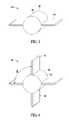
- FIG. 3is a perspective view of an exemplary dual blade discharge electrode
- FIG. 4is a perspective view of an exemplary quad blade discharge electrode
- FIG. 5is a perspective view of an exemplary opposed pin discharge electrode
- FIG. 6is a perspective view of an exemplary V-pin discharge electrode
- FIG. 7is a graph of exemplary discharge electrode performance curves.
- FIG. 1is a perspective view of an exemplary electrostatic precipitator 10 .
- FIG. 2is a top cross-sectional view of electrostatic precipitator 10 .
- precipitator 10includes a body 12 that has an entry channel 14 , an exit channel 16 and a collector chamber 18 positioned between entry channel 14 and exit channel 16 .
- Collector chamber 18includes an inner top surface 20 and a plurality of rigid discharge electrodes 22 that each extend from surface 20 .
- Collector chamber 18also includes a plurality of collector electrodes 24 that are suspended from inner surface 20 . Electrodes 24 are positioned within a flow path 26 that extends from entry channel 14 through collector chamber 18 and to exit channel 16 .
- Collector electrodes 24are square plates that are positioned substantially parallel to, and uniformly spaced from, each other such that a gap 28 is defined between adjacent electrodes 24 .
- Each of the plurality of discharge electrodes 22extends from surface 20 into gap 28 between adjacent collector electrodes 24 .
- collector chamber 18includes a bottom surface 30 that includes a plurality of sloughing channels 32 that are positioned above a hopper (not shown). Each sloughing channel 32 includes at least two sides 34 that slope towards an exit passage 36 .
- collector electrodes 24are described as square plates, collector electrodes 24 may be any collector electrode, that enables electrostatic precipitator 10 to function as described herein, such as, but not limited to, plain wire, barbed wire, spiral wire, twisted round wire, twisted square wire, thin metal sheets cut with points and a tube with various styles of pins, barbs, projections or edges.
- fluid containing suspended particles 38is channeled through entry channel 14 into collector chamber 18 .
- the fluidchanneled along flow path 26 between collector electrodes 24 .
- Rigid discharge electrodes 22are charged with a high current, creating a corona of electrons and an associated electric field which ionizes suspended particles 38 causing particles 38 to migrate towards collector electrodes 24 .
- discharge electrodes 22have a negative potential and collector electrodes 24 have a positive potential.
- rigid discharge electrodes 22charge suspended particles 38 and collector electrodes 24 collect suspended particles 38 .
- the term “fluid” as used hereinincludes any material or medium that flows, including but not limited to, gas, air and liquids.
- collector chamber 18is divided into a plurality of electric fields that are each defined by a corresponding discharge electrode 22 .
- impedance of each electric fieldis a function of the amount of dust in the electric field.
- each rigid discharge electrode 22is aligned with the impedance of its associated electric field.
- matching the impedance of each rigid discharge electrode 22 with the impedance of its associated electric fieldis accomplished by altering the geometry of each rigid discharge electrode 22 .
- Altering the geometry of each rigid discharge electrode 22also modifies the relationship between a secondary voltage and a secondary current.
- the geometry of each rigid discharge electrode 22may be altered by adjusting a pin length, pin spacing, tube diameter and pin angle.
- a voltageis applied to each discharge electrode 22 , and when a pre-determined voltage is applied a corona begins to develop and a secondary current begins to develop between discharge electrode 22 and collector electrode 24 .
- Corona onset voltageis defined as the point at which measurable secondary current is first observed. After the corona onset voltage is reached, for each increase in the applied voltage there is an increase in the secondary current. It should be understood that applied voltages exceeding the corona onset voltage are considered secondary voltages. Moreover, it should be understood that for a given rigid electrode geometry and fluid conditions, the applied secondary voltage drives the level of secondary current realized.
- discharge electrodeseach have a V-I performance curve determined by plotting applied secondary voltage versus measured secondary current. In electrodes, the current is dependent and increases exponentially with the voltage, and maximizing the secondary voltage may optimize precipitator performance.
- FIG. 3is a perspective view of an exemplary dual blade discharge electrode 40 .
- dual blade discharge electrode 40includes a central discharge electrode body 42 having an outer surface 44 and two blades 46 extending radially outward therefrom.
- electrode body 42is cylindrically-shaped and has a substantially circular cross-section. Blades 46 are positioned about outer surface 44 , extend generally radially outward from surface 44 , and are diametrically opposed to each other. It should be appreciated that although the exemplary embodiment is described as including an electrode body 42 having a substantially circular cross-section, in other embodiments, electrode body 42 may have any cross-sectional shape that enables discharge electrode 40 to function as described herein.
- FIG. 4is a perspective view of an exemplary quad blade discharge electrode 48 .
- dual blade discharge electrode 48includes a central discharge electrode body 50 having an outer surface 52 and four blades 54 extending radially outward therefrom.
- electrode body 50is cylindrically-shaped and has a substantially circular cross-section.
- Blades 54are positioned about the periphery of outer surface 52 , are separated by an angle ⁇ of approximately ninety degrees and extend generally radially outward from outer surface 52 .
- angle ⁇ between blades 54may be any angle ⁇ , not necessarily equal, that enables discharge electrode 48 to function as described herein.
- FIG. 5is a perspective view of an exemplary opposed pin discharge electrode 56 .
- opposed pin discharge electrode 56includes a central discharge electrode body 58 having an outer surface 60 and two pins 62 extending radially outward therefrom.
- Electrode body 58is cylindrically-shaped and has a substantially circular cross-section.
- Pins 62have a length L of approximately 11 ⁇ 2 inches, are positioned at an angle ⁇ of approximately one hundred eighty degrees from each other about the periphery of outer surface 60 and extend radially outward from outer surface 60 .
- electrode body 58may have any cross-sectional shape that enables discharge electrode 56 to function as described herein.
- angle ⁇ between pins 62may be any angle ⁇ that enables discharge electrode 56 to function as described herein.
- pins 62may have any length L that enables discharge electrode 56 to function as described herein.
- FIG. 6is a perspective view of an exemplary V-pin discharge electrode 64 . More specifically, V-pin discharge electrode 64 includes a central discharge electrode body 66 having an outer surface 68 and four pins 70 extending radially outward therefrom. Electrode body 66 is cylindrically-shaped and has a substantially circular cross-section. Pins 70 have a length L 1 , are positioned in pairs about the periphery of outer surface 68 , and extend radially outward from outer surface 68 . Each pair of pins 70 includes two pins 70 separated at an acute angle ⁇ about outer surface 68 such that each pair of pins 70 defines a generally V-shaped configuration.
- each pin 70 included in each pair of pinsis diametrically opposed to another pin included in another pair of pins.
- electrode body 66may have any cross-sectional shape that enables discharge electrode 64 to function as described herein.
- angle ⁇ between pins 70may be any acute angle ⁇ that enables discharge electrode 64 to function as described herein.
- length L 1 of pins 70may be any length that enables discharge electrode 64 to function as described herein.
- FIG. 7is a graph showing exemplary curves of secondary voltage plotted against secondary current for a plurality of rigid discharge electrode 22 embodiments. These curves are known as V-I performance curves. More specifically, V-I curves are shown for dual blade discharge electrode 40 , quad blade discharge electrode 48 , opposed pin discharge electrodes 56 and V-pin discharge electrode 64 .
- the V-I performance curve of dual blade discharge electrode 40shows that providing dual blades in this configuration results in relatively low secondary current at an applied secondary voltage.
- the V-I performance graph for quad blade discharge electrode 48shows that providing quad blades in this configuration results in relatively high secondary currents at an applied secondary voltage, versus dual blade discharge electrode 40 .
- the V-I performance graph of dual pin discharge electrode 56shows that providing dual pins 62 in this configuration, and having a length L of 1-1 ⁇ 2 inches, facilitates providing secondary voltages and secondary currents intermediate those provided by dual blade electrode 40 and quad blade electrode 48 .
- Modifying the length L of pins 62alters the V-I performance of dual pin electrode 56 . For example, by increasing the length L to two inches, dual pin electrode 56 provides marginally less secondary current at the same secondary voltage versus using L of 1-1 ⁇ 2 inches. By increasing length L to three inches, dual pin electrode 56 provides smaller corresponding secondary current than both 1-1 ⁇ 2 and 2 inch pins 62 at the same secondary voltage.
- V-I performance graph of V-pin discharge electrode 64provides discharge electrode performance similar to quad blade electrode 48 . However, starting at about a secondary voltage of about 45 kV V-pin electrode 64 provides increased secondary current for the same secondary voltage versus quad blade electrode 48 .
- each of the discharge electrode exemplary embodiments 40 , 48 , 56 and 64 described hereinis based on empirical data reflecting process parameters, such as, but not limited to, precipitator configuration, particle resistivity and operating volume, as well as the V-I curve of an electric field and a transformer/rectifier's rating.
- discharge electrode 22For low dust loading composed of primarily fine particles, discharge electrode 22 should be designed to maintain relatively high voltage to maintain adequate electric field strength without reaching a secondary current limit of the power supply.
- dual blade discharge electrode 40is the most effective for removing fine particles from the fluid.
- discharge electrodes 22For heavy dust loading composed primarily of coarse particles, discharge electrodes 22 should be designed to produce high secondary current at an applied secondary voltage. This maximizes charging of the dust with the available electric field.
- quad blade discharge electrode 48operates at a high secondary current with a minimal secondary voltage to provide the best charging, and is the most effective at removing coarse particles from the fluid.
- V-I performance characteristics of discharge electrodes 22may be used to determine their most effective location within precipitator 10 .
- the first electric field of precipitator inletscollects about eighty percent of the particles contained in the dust, and these particles are generally coarse. Consequently, positioning quad blade discharge electrodes 48 proximate precipitator inlet 14 facilitates optimizing coarse particle removal from the fluid.
- electric fields located downstream from the first electric fieldsencounter less dust than the first electric field and the dust generally contains finer particles. Consequently, positioning dual blade discharge electrodes 40 proximate precipitator outlet 16 facilitates optimizing fine particle removal from the fluid.
- the fluid in chamber 18 flowing from inlet 14 towards outlet 16contains progressively fewer coarse particles and progressively more fine particles, on a percentage basis.
- electrostatic precipitators 10may be designed to contain discharge electrodes 22 that are specifically positioned within precipitator 10 for facilitating optimal particle removal in a particular region of electrostatic precipitators 10 .
- Rigid discharge electrodes 22 operating at a high secondary current for a given secondary voltageshould be positioned proximate precipitator areas containing heavy loading of coarse particles.
- Discharge electrodes 22 operating with high secondary current while maintaining adequate secondary voltageshould be positioned proximate precipitator areas containing lower dust loading of fine particles.
- Discharge electrodes 22 with intermediate secondary voltage and intermediate secondary currentshould be positioned proximate precipitator areas containing a mix of coarse and fine particles.
- the above-described rigid discharge electrodesfacilitate operating transformer/rectifiers closer to their maximum ratings. More specifically, in each embodiment, by modifying rigid discharge electrode geometry the relationship between the secondary voltage and the secondary current is modified such that V-I curves are designed to facilitate matching the impedance of the discharge electrode with its associated electric field, thus, optimizing the power input into the electric field. As a result, operating voltage is facilitated to be maximized, operating performance is facilitated to be improved and the cost of rebuilding electrostatic precipitators is facilitated to be reduced. Accordingly, electrostatic precipitator performance and component useful life are each facilitated to be enhanced in a cost effective and reliable manner.
- rigid discharge electrodesExemplary embodiments of rigid discharge electrodes are described above in detail.
- the rigid discharge electrodesare not limited to use with the specific precipitator embodiment described herein, but rather, the rigid discharge electrodes can be utilized independently and separately from other rigid discharge electrode components described herein.
- the inventionis not limited to the embodiments of the rigid discharge electrodes described above in detail. Rather, other variations of rigid discharge electrode embodiments may be utilized within the spirit and scope of the claims.
Landscapes
- Electrostatic Separation (AREA)
Abstract
Description
Claims (14)
Priority Applications (5)
| Application Number | Priority Date | Filing Date | Title |
|---|---|---|---|
| US11/763,195US7655068B2 (en) | 2007-06-14 | 2007-06-14 | Method and systems to facilitate improving electrostatic precipitator performance |
| GB0809670.3AGB2450212B (en) | 2007-06-14 | 2008-05-28 | Method and systems to facilitate improving electrostatic precipitator performance |
| DE102008002879ADE102008002879A1 (en) | 2007-06-14 | 2008-06-10 | Method and system for improving the performance of electrostatic precipitators |
| JP2008152355AJP5377892B2 (en) | 2007-06-14 | 2008-06-11 | A system that facilitates improving the performance of electrostatic precipitators |
| KR1020080055317AKR101515633B1 (en) | 2007-06-14 | 2008-06-12 | Method and systems to facilitate improving electrostatic precipitator performance |
Applications Claiming Priority (1)
| Application Number | Priority Date | Filing Date | Title |
|---|---|---|---|
| US11/763,195US7655068B2 (en) | 2007-06-14 | 2007-06-14 | Method and systems to facilitate improving electrostatic precipitator performance |
Publications (2)
| Publication Number | Publication Date |
|---|---|
| US20080307974A1 US20080307974A1 (en) | 2008-12-18 |
| US7655068B2true US7655068B2 (en) | 2010-02-02 |
Family
ID=39616207
Family Applications (1)
| Application Number | Title | Priority Date | Filing Date |
|---|---|---|---|
| US11/763,195Expired - Fee RelatedUS7655068B2 (en) | 2007-06-14 | 2007-06-14 | Method and systems to facilitate improving electrostatic precipitator performance |
Country Status (5)
| Country | Link |
|---|---|
| US (1) | US7655068B2 (en) |
| JP (1) | JP5377892B2 (en) |
| KR (1) | KR101515633B1 (en) |
| DE (1) | DE102008002879A1 (en) |
| GB (1) | GB2450212B (en) |
Families Citing this family (3)
| Publication number | Priority date | Publication date | Assignee | Title |
|---|---|---|---|---|
| FR2927550B1 (en)* | 2008-02-19 | 2011-04-22 | Commissariat Energie Atomique | ELECTROSTATIC FILTRATION DEVICE USING OPTIMIZED EMISSIVE SITES. |
| KR101970781B1 (en)* | 2015-04-30 | 2019-04-19 | 주식회사 엔아이티코리아 | A Electrical Dust Filter Having a Structure of an Elastic Electrode |
| KR101783179B1 (en)* | 2015-06-29 | 2017-09-28 | 한국전력공사 | Apparatus for Recovering of Fine Fly Ashes with High Rare Earth Element |
Citations (24)
| Publication number | Priority date | Publication date | Assignee | Title |
|---|---|---|---|---|
| US2042181A (en)* | 1932-07-30 | 1936-05-26 | Westinghouse Electric & Mfg Co | Control circuit |
| US2881855A (en)* | 1953-05-04 | 1959-04-14 | Apra Precipitator Corp | Precipitator flashover control through current and voltage response |
| US3049848A (en)* | 1953-08-17 | 1962-08-21 | Apra Precipitator Corp | Electrostatic precipitator circuits |
| US3740926A (en) | 1970-12-15 | 1973-06-26 | Texas Electronic Precipitator | Portable electronic precipitator |
| US4244709A (en) | 1979-07-13 | 1981-01-13 | Union Carbide Corporation | High intensity ionization-electrostatic precipitation system for particle removal and method of operation |
| US4311491A (en)* | 1980-08-18 | 1982-01-19 | Research Cottrell, Inc. | Electrostatic precipitator control for high resistivity particulate |
| GB2096845A (en)* | 1981-04-08 | 1982-10-20 | Mitsubishi Heavy Ind Ltd | Electric dust collecting apparatus |
| JPS6125650A (en)* | 1984-07-17 | 1986-02-04 | Sumitomo Heavy Ind Ltd | Method for controlling electrical charge of electrical dust precipitator |
| US4654772A (en)* | 1986-03-06 | 1987-03-31 | Fyrnetics, Inc. | Power supply for electrostatic air cleaner |
| US4808200A (en)* | 1986-11-24 | 1989-02-28 | Siemens Aktiengesellschaft | Electrostatic precipitator power supply |
| US4936876A (en)* | 1986-11-19 | 1990-06-26 | F. L. Smidth & Co. A/S | Method and apparatus for detecting back corona in an electrostatic filter with ordinary or intermittent DC-voltage supply |
| US4966610A (en) | 1989-06-05 | 1990-10-30 | Wahlco, Inc. | Conditioning of gas streams containing particulate |
| US5282891A (en) | 1992-05-01 | 1994-02-01 | Ada Technologies, Inc. | Hot-side, single-stage electrostatic precipitator having reduced back corona discharge |
| US5378978A (en)* | 1993-04-02 | 1995-01-03 | Belco Technologies Corp. | System for controlling an electrostatic precipitator using digital signal processing |
| US5471377A (en)* | 1990-04-04 | 1995-11-28 | Siemens Aktiengesellschaft | Process for controlling a power supply which supplies power to an electrostatic filter in which secondary circuit states are determined based on measured primary circuit values and in which short circuits are detected |
| US5567226A (en) | 1992-10-09 | 1996-10-22 | Lookman; Aziz A. | Apparatus and method for enhancing the performance of a particulate collection device |
| US5707422A (en)* | 1993-03-01 | 1998-01-13 | Abb Flakt Ab | Method of controlling the supply of conditioning agent to an electrostatic precipitator |
| US5922103A (en) | 1995-10-12 | 1999-07-13 | Envirocare International Inc. | Automatic gas conditioning method |
| US5980610A (en) | 1997-09-25 | 1999-11-09 | The United States Of America As Represented By The United States Department Of Energy | Apparatus and method for improving electrostatic precipitator performance by plasma reactor conversion of SO2 to SO3 |
| US20010011499A1 (en)* | 1998-09-18 | 2001-08-09 | Victor Reyes | Method of operating an electrostatic precipitator |
| US6363869B1 (en) | 1999-02-03 | 2002-04-02 | Clearstack Combustion Corporation | Potassium hydroxide flue gas injection technique to reduce acid gas emissions and improve electrostatic precipitator performance |
| US6540812B2 (en) | 2001-07-06 | 2003-04-01 | Bha Group Holdings, Inc. | Method and system for improved rapper control |
| US6797035B2 (en) | 2002-08-30 | 2004-09-28 | Ada Environmental Solutions, Llc | Oxidizing additives for control of particulate emissions |
| US7497893B2 (en)* | 2002-06-21 | 2009-03-03 | Kronos Advanced Technologies, Inc. | Method of electrostatic acceleration of a fluid |
Family Cites Families (14)
| Publication number | Priority date | Publication date | Assignee | Title |
|---|---|---|---|---|
| US4183736A (en)* | 1972-08-17 | 1980-01-15 | High Voltage Engineering Corporation | Electrostatic precipitation |
| US4094653A (en)* | 1973-08-14 | 1978-06-13 | Senichi Masuda | Particle charging device and an electric dust collecting apparatus making use of said device |
| JPS50105080U (en)* | 1974-01-31 | 1975-08-29 | ||
| JPS5167585A (en)* | 1974-12-09 | 1976-06-11 | Metallgesellschaft Ag | DENKISHUJINSOCHI |
| JPS52156473A (en)* | 1976-06-21 | 1977-12-26 | Senichi Masuda | Pulse charge type electric dust collector |
| GB2068659B (en)* | 1980-02-02 | 1984-09-19 | Cottrell Res Inc | Control of electrostatic precipitators |
| JPS60165050U (en)* | 1983-12-28 | 1985-11-01 | 三興空気装置株式会社 | Electrostatic classification device for powder particles |
| JP2738424B2 (en)* | 1987-07-24 | 1998-04-08 | 日立プラント建設株式会社 | Electric dust collecting device for collecting submicron particles |
| SE463077B (en)* | 1988-06-03 | 1990-10-08 | Boliden Contech Ab | the emission electrodes |
| JP3268041B2 (en)* | 1992-12-25 | 2002-03-25 | 三菱重工業株式会社 | Duct type electrostatic precipitator |
| JP2562557B2 (en)* | 1993-06-04 | 1996-12-11 | 日立プラント建設 株式会社 | Electric dust collector charging method |
| JP3073393B2 (en)* | 1994-05-27 | 2000-08-07 | 大見工業株式会社 | Electrostatic dust collector |
| JPH10277432A (en)* | 1997-04-07 | 1998-10-20 | Sumitomo Heavy Ind Ltd | Electrostatic dust collecting method and electrostatic precipitator |
| CA2489983A1 (en)* | 2002-06-21 | 2004-06-17 | Kronos Advanced Technologies Inc. | An electrostatic fluid accelerator for and method of controlling a fluid flow |
- 2007
- 2007-06-14USUS11/763,195patent/US7655068B2/ennot_activeExpired - Fee Related
- 2008
- 2008-05-28GBGB0809670.3Apatent/GB2450212B/ennot_activeExpired - Fee Related
- 2008-06-10DEDE102008002879Apatent/DE102008002879A1/ennot_activeWithdrawn
- 2008-06-11JPJP2008152355Apatent/JP5377892B2/ennot_activeExpired - Fee Related
- 2008-06-12KRKR1020080055317Apatent/KR101515633B1/ennot_activeExpired - Fee Related
Patent Citations (25)
| Publication number | Priority date | Publication date | Assignee | Title |
|---|---|---|---|---|
| US2042181A (en)* | 1932-07-30 | 1936-05-26 | Westinghouse Electric & Mfg Co | Control circuit |
| US2881855A (en)* | 1953-05-04 | 1959-04-14 | Apra Precipitator Corp | Precipitator flashover control through current and voltage response |
| US3049848A (en)* | 1953-08-17 | 1962-08-21 | Apra Precipitator Corp | Electrostatic precipitator circuits |
| US3740926A (en) | 1970-12-15 | 1973-06-26 | Texas Electronic Precipitator | Portable electronic precipitator |
| US4244709A (en) | 1979-07-13 | 1981-01-13 | Union Carbide Corporation | High intensity ionization-electrostatic precipitation system for particle removal and method of operation |
| US4311491A (en)* | 1980-08-18 | 1982-01-19 | Research Cottrell, Inc. | Electrostatic precipitator control for high resistivity particulate |
| GB2096845A (en)* | 1981-04-08 | 1982-10-20 | Mitsubishi Heavy Ind Ltd | Electric dust collecting apparatus |
| JPS6125650A (en)* | 1984-07-17 | 1986-02-04 | Sumitomo Heavy Ind Ltd | Method for controlling electrical charge of electrical dust precipitator |
| US4648887A (en)* | 1984-07-17 | 1987-03-10 | Sumitomo Heavy Industries, Ltd. | Method for controlling electrostatic precipitator |
| US4654772A (en)* | 1986-03-06 | 1987-03-31 | Fyrnetics, Inc. | Power supply for electrostatic air cleaner |
| US4936876A (en)* | 1986-11-19 | 1990-06-26 | F. L. Smidth & Co. A/S | Method and apparatus for detecting back corona in an electrostatic filter with ordinary or intermittent DC-voltage supply |
| US4808200A (en)* | 1986-11-24 | 1989-02-28 | Siemens Aktiengesellschaft | Electrostatic precipitator power supply |
| US4966610A (en) | 1989-06-05 | 1990-10-30 | Wahlco, Inc. | Conditioning of gas streams containing particulate |
| US5471377A (en)* | 1990-04-04 | 1995-11-28 | Siemens Aktiengesellschaft | Process for controlling a power supply which supplies power to an electrostatic filter in which secondary circuit states are determined based on measured primary circuit values and in which short circuits are detected |
| US5282891A (en) | 1992-05-01 | 1994-02-01 | Ada Technologies, Inc. | Hot-side, single-stage electrostatic precipitator having reduced back corona discharge |
| US5567226A (en) | 1992-10-09 | 1996-10-22 | Lookman; Aziz A. | Apparatus and method for enhancing the performance of a particulate collection device |
| US5707422A (en)* | 1993-03-01 | 1998-01-13 | Abb Flakt Ab | Method of controlling the supply of conditioning agent to an electrostatic precipitator |
| US5378978A (en)* | 1993-04-02 | 1995-01-03 | Belco Technologies Corp. | System for controlling an electrostatic precipitator using digital signal processing |
| US5922103A (en) | 1995-10-12 | 1999-07-13 | Envirocare International Inc. | Automatic gas conditioning method |
| US5980610A (en) | 1997-09-25 | 1999-11-09 | The United States Of America As Represented By The United States Department Of Energy | Apparatus and method for improving electrostatic precipitator performance by plasma reactor conversion of SO2 to SO3 |
| US20010011499A1 (en)* | 1998-09-18 | 2001-08-09 | Victor Reyes | Method of operating an electrostatic precipitator |
| US6363869B1 (en) | 1999-02-03 | 2002-04-02 | Clearstack Combustion Corporation | Potassium hydroxide flue gas injection technique to reduce acid gas emissions and improve electrostatic precipitator performance |
| US6540812B2 (en) | 2001-07-06 | 2003-04-01 | Bha Group Holdings, Inc. | Method and system for improved rapper control |
| US7497893B2 (en)* | 2002-06-21 | 2009-03-03 | Kronos Advanced Technologies, Inc. | Method of electrostatic acceleration of a fluid |
| US6797035B2 (en) | 2002-08-30 | 2004-09-28 | Ada Environmental Solutions, Llc | Oxidizing additives for control of particulate emissions |
Also Published As
| Publication number | Publication date |
|---|---|
| US20080307974A1 (en) | 2008-12-18 |
| GB2450212A (en) | 2008-12-17 |
| DE102008002879A1 (en) | 2008-12-24 |
| KR101515633B1 (en) | 2015-04-27 |
| KR20080110511A (en) | 2008-12-18 |
| GB2450212B (en) | 2012-04-04 |
| GB0809670D0 (en) | 2008-07-02 |
| JP5377892B2 (en) | 2013-12-25 |
| JP2008307534A (en) | 2008-12-25 |
Similar Documents
| Publication | Publication Date | Title |
|---|---|---|
| US8597415B2 (en) | Electric precipitator and air cleaner having the same | |
| US4342571A (en) | Electrostatic precipitator | |
| Chen et al. | A high efficiency, high throughput unipolar aerosol charger for nanoparticles | |
| CN101180131B (en) | Wet Electrostatic Ionization Stage in Electrostatic Separation Units | |
| US20050150384A1 (en) | Electrostatic air cleaning device | |
| US7655068B2 (en) | Method and systems to facilitate improving electrostatic precipitator performance | |
| US20090165648A1 (en) | Method and Apparatus for Electrostatically Charging and Separating Particles That Are Difficult to Separate | |
| US20250025890A1 (en) | Air filtering device for an air conditioner | |
| CN107104030B (en) | Ion beam irradiation apparatus | |
| US20050028676A1 (en) | Corona discharge electrode assembly for electrostatic precipitator | |
| US9039815B2 (en) | Vane electrostatic precipitator | |
| US20080175720A1 (en) | Contoured electrodes for an electrostatic gas pump | |
| US2199390A (en) | Electrical precipitation | |
| JP3376338B2 (en) | Helical screw type high efficiency dust charging device | |
| US2817413A (en) | Electrostatic precipitators | |
| KR20200117868A (en) | Electrostatic charger and Electrostatic precipitator | |
| KR20170053865A (en) | Electric Dust Collection Device | |
| EP3272422B1 (en) | Scroll type electrostatic precipitator and air conditioning apparatus having the same | |
| JP2872554B2 (en) | Electric dust collector | |
| KR20190032107A (en) | Charging Unit and Electric Dust Collection Device having the same | |
| JP2009061444A (en) | Electrostatic dust collector and charger | |
| JP2562557B2 (en) | Electric dust collector charging method | |
| RU2830663C1 (en) | Electrode for electrostatic separator and electrostatic separator | |
| KR101377977B1 (en) | Electrical precipitator | |
| CN211914183U (en) | Air purification apparatus for separating airborne particles from an air stream |
Legal Events
| Date | Code | Title | Description |
|---|---|---|---|
| AS | Assignment | Owner name:GENERAL ELECTRIC COMPANY, NEW YORK Free format text:ASSIGNMENT OF ASSIGNORS INTEREST;ASSIGNORS:JOHNSTON, DAVID;ROBERTS, JAMES EASEL;TAYLOR, ROBERT WARREN;AND OTHERS;REEL/FRAME:019431/0151;SIGNING DATES FROM 20070403 TO 20070412 Owner name:GENERAL ELECTRIC COMPANY,NEW YORK Free format text:ASSIGNMENT OF ASSIGNORS INTEREST;ASSIGNORS:JOHNSTON, DAVID;ROBERTS, JAMES EASEL;TAYLOR, ROBERT WARREN;AND OTHERS;SIGNING DATES FROM 20070403 TO 20070412;REEL/FRAME:019431/0151 | |
| FEPP | Fee payment procedure | Free format text:PAYOR NUMBER ASSIGNED (ORIGINAL EVENT CODE: ASPN); ENTITY STATUS OF PATENT OWNER: LARGE ENTITY Free format text:PAYER NUMBER DE-ASSIGNED (ORIGINAL EVENT CODE: RMPN); ENTITY STATUS OF PATENT OWNER: LARGE ENTITY | |
| FEPP | Fee payment procedure | Free format text:PAYOR NUMBER ASSIGNED (ORIGINAL EVENT CODE: ASPN); ENTITY STATUS OF PATENT OWNER: LARGE ENTITY | |
| AS | Assignment | Owner name:BABCOCK & WILCOX POWER GENERATION GROUP, INC.,OHIO Free format text:ASSIGNMENT OF ASSIGNORS INTEREST;ASSIGNOR:GENERAL ELECTRIC COMPANY;REEL/FRAME:024474/0894 Effective date:20100401 Owner name:BABCOCK & WILCOX POWER GENERATION GROUP, INC., OHI Free format text:ASSIGNMENT OF ASSIGNORS INTEREST;ASSIGNOR:GENERAL ELECTRIC COMPANY;REEL/FRAME:024474/0894 Effective date:20100401 | |
| XAS | Not any more in us assignment database | Free format text:ASSIGNMENT OF ASSIGNORS INTEREST;ASSIGNOR:GENERAL ELECTRIC COMPANY;REEL/FRAME:024474/0894 | |
| AS | Assignment | Owner name:BABCOCK & WILCOX POWER GENERATION GROUP, INC., OHI Free format text:CORRECTIVE ASSIGNMENT TO CORRECT THE ADDRESS PREVIOUSLY RECORDED ON REEL 024474 FRAME 0894. ASSIGNOR(S) HEREBY CONFIRMS THE ADDRESS IS 1 RIVER ROAD, SCHENECTADY, NEW YORK, 12345 AND NOT 8800 63RD STREET, KANSAS CITY, MO 64133;ASSIGNOR:GENERAL ELECTRIC COMPANY;REEL/FRAME:025455/0728 Effective date:20100401 | |
| AS | Assignment | Owner name:BANK OF AMERICA, N.A., AS ADMINISTRATIVE AGENT, CA Free format text:NOTICE OF GRANT OF SECURITY INTEREST IN PATENTS;ASSIGNOR:BABCOCK & WILCOX POWER GENERATION GROUP, INC.;REEL/FRAME:028456/0706 Effective date:20120608 | |
| FPAY | Fee payment | Year of fee payment:4 | |
| AS | Assignment | Owner name:BANK OF AMERICA, N.A., AS ADMINISTRATIVE AGENT, CA Free format text:SECURITY INTEREST;ASSIGNOR:BABCOCK & WILCOX POWER GENERATION GROUP, INC. (TO BE RENAMED THE BABCOCK AND WILCOX COMPANY);REEL/FRAME:036201/0598 Effective date:20150630 | |
| AS | Assignment | Owner name:THE BABCOCK & WILCOX COMPANY, OHIO Free format text:CHANGE OF NAME;ASSIGNOR:BABCOCK & WILCOX POWER GENERATION GROUP, INC.;REEL/FRAME:036675/0434 Effective date:20150630 | |
| FEPP | Fee payment procedure | Free format text:MAINTENANCE FEE REMINDER MAILED (ORIGINAL EVENT CODE: REM.) | |
| LAPS | Lapse for failure to pay maintenance fees | Free format text:PATENT EXPIRED FOR FAILURE TO PAY MAINTENANCE FEES (ORIGINAL EVENT CODE: EXP.) | |
| STCH | Information on status: patent discontinuation | Free format text:PATENT EXPIRED DUE TO NONPAYMENT OF MAINTENANCE FEES UNDER 37 CFR 1.362 | |
| FP | Lapsed due to failure to pay maintenance fee | Effective date:20180202 | |
| AS | Assignment | Owner name:BABCOCK & WILCOX MEGTEC, LLC, WISCONSIN Free format text:RELEASE BY SECURED PARTY;ASSIGNOR:BANK OF AMERICA, N.A.;REEL/FRAME:057337/0823 Effective date:20210630 Owner name:SOFCO-EFS HOLDINGS LLC, OHIO Free format text:RELEASE BY SECURED PARTY;ASSIGNOR:BANK OF AMERICA, N.A.;REEL/FRAME:057337/0823 Effective date:20210630 Owner name:BABCOCK & WILCOX TECHNOLOGY, LLC (F/K/A MCDERMOTT TECHNOLOGY, INC.), OHIO Free format text:RELEASE BY SECURED PARTY;ASSIGNOR:BANK OF AMERICA, N.A.;REEL/FRAME:057337/0823 Effective date:20210630 Owner name:BABCOCK & WILCOX SPIG, INC., OHIO Free format text:RELEASE BY SECURED PARTY;ASSIGNOR:BANK OF AMERICA, N.A.;REEL/FRAME:057337/0823 Effective date:20210630 Owner name:THE BABCOCK & WILCOX COMPANY (F/K/A BABCOCK & WILCOX POWER GENERATION GROUP, INC.), OHIO Free format text:RELEASE BY SECURED PARTY;ASSIGNOR:BANK OF AMERICA, N.A.;REEL/FRAME:057337/0823 Effective date:20210630 Owner name:MEGTEC TURBOSONIC TECHNOLOGIES, INC., ONTARIO Free format text:RELEASE BY SECURED PARTY;ASSIGNOR:BANK OF AMERICA, N.A.;REEL/FRAME:057337/0823 Effective date:20210630 Owner name:DIAMOND POWER INTERNATIONAL, LLC (F/K/A DIAMOND POWER INTERNATIONAL, INC.), OHIO Free format text:RELEASE BY SECURED PARTY;ASSIGNOR:BANK OF AMERICA, N.A.;REEL/FRAME:057337/0823 Effective date:20210630 |