US7655039B2 - Stents with attached looped ends - Google Patents
Stents with attached looped endsDownload PDFInfo
- Publication number
- US7655039B2 US7655039B2US10/852,495US85249504AUS7655039B2US 7655039 B2US7655039 B2US 7655039B2US 85249504 AUS85249504 AUS 85249504AUS 7655039 B2US7655039 B2US 7655039B2
- Authority
- US
- United States
- Prior art keywords
- strand
- couplings
- strands
- prosthesis
- closure members
- Prior art date
- Legal status (The legal status is an assumption and is not a legal conclusion. Google has not performed a legal analysis and makes no representation as to the accuracy of the status listed.)
- Active, expires
Links
- 230000008878couplingEffects0.000claimsabstractdescription100
- 238000010168coupling processMethods0.000claimsabstractdescription100
- 238000005859coupling reactionMethods0.000claimsabstractdescription100
- 230000004927fusionEffects0.000claimsabstractdescription7
- 239000000853adhesiveSubstances0.000claimsdescription5
- 230000001070adhesive effectEffects0.000claimsdescription5
- 238000005304joiningMethods0.000claimsdescription3
- 238000003466weldingMethods0.000abstractdescription5
- 208000027418Wounds and injuryDiseases0.000description14
- 238000010276constructionMethods0.000description9
- 208000014674injuryDiseases0.000description9
- 230000008602contractionEffects0.000description7
- 230000008733traumaEffects0.000description6
- 239000000463materialSubstances0.000description5
- 238000000034methodMethods0.000description5
- 238000005452bendingMethods0.000description4
- 230000006378damageEffects0.000description4
- 238000007493shaping processMethods0.000description4
- 210000004204blood vesselAnatomy0.000description3
- PXHVJJICTQNCMI-UHFFFAOYSA-NNickelChemical compound[Ni]PXHVJJICTQNCMI-UHFFFAOYSA-N0.000description2
- 240000007643Phytolacca americanaSpecies0.000description2
- 238000013459approachMethods0.000description2
- 230000003190augmentative effectEffects0.000description2
- 230000008901benefitEffects0.000description2
- 230000006835compressionEffects0.000description2
- 238000007906compressionMethods0.000description2
- 230000006355external stressEffects0.000description2
- 229910052751metalInorganic materials0.000description2
- 239000002184metalSubstances0.000description2
- 229910001000nickel titaniumInorganic materials0.000description2
- HLXZNVUGXRDIFK-UHFFFAOYSA-Nnickel titaniumChemical compound[Ti].[Ti].[Ti].[Ti].[Ti].[Ti].[Ti].[Ti].[Ti].[Ti].[Ti].[Ni].[Ni].[Ni].[Ni].[Ni].[Ni].[Ni].[Ni].[Ni].[Ni].[Ni].[Ni].[Ni].[Ni]HLXZNVUGXRDIFK-UHFFFAOYSA-N0.000description2
- 229920000139polyethylene terephthalatePolymers0.000description2
- 239000005020polyethylene terephthalateSubstances0.000description2
- 238000004804windingMethods0.000description2
- 229910000531Co alloyInorganic materials0.000description1
- 229910000990Ni alloyInorganic materials0.000description1
- 229910000831SteelInorganic materials0.000description1
- 229910001069Ti alloyInorganic materials0.000description1
- 229910045601alloyInorganic materials0.000description1
- 239000000956alloySubstances0.000description1
- 230000004323axial lengthEffects0.000description1
- 230000009286beneficial effectEffects0.000description1
- 238000002788crimpingMethods0.000description1
- 238000002405diagnostic procedureMethods0.000description1
- 230000000694effectsEffects0.000description1
- 229910000701elgiloys (Co-Cr-Ni Alloy)Inorganic materials0.000description1
- 238000009998heat settingMethods0.000description1
- 238000004519manufacturing processMethods0.000description1
- 238000002844meltingMethods0.000description1
- 230000008018meltingEffects0.000description1
- 229920000728polyesterPolymers0.000description1
- -1polyethylene terephthalatePolymers0.000description1
- 229920000642polymerPolymers0.000description1
- 229910001285shape-memory alloyInorganic materials0.000description1
- 238000004904shorteningMethods0.000description1
- 229910001220stainless steelInorganic materials0.000description1
- 239000010959steelSubstances0.000description1
- 229910052715tantalumInorganic materials0.000description1
- GUVRBAGPIYLISA-UHFFFAOYSA-Ntantalum atomChemical compound[Ta]GUVRBAGPIYLISA-UHFFFAOYSA-N0.000description1
Images


Classifications
- A—HUMAN NECESSITIES
- A61—MEDICAL OR VETERINARY SCIENCE; HYGIENE
- A61F—FILTERS IMPLANTABLE INTO BLOOD VESSELS; PROSTHESES; DEVICES PROVIDING PATENCY TO, OR PREVENTING COLLAPSING OF, TUBULAR STRUCTURES OF THE BODY, e.g. STENTS; ORTHOPAEDIC, NURSING OR CONTRACEPTIVE DEVICES; FOMENTATION; TREATMENT OR PROTECTION OF EYES OR EARS; BANDAGES, DRESSINGS OR ABSORBENT PADS; FIRST-AID KITS
- A61F2/00—Filters implantable into blood vessels; Prostheses, i.e. artificial substitutes or replacements for parts of the body; Appliances for connecting them with the body; Devices providing patency to, or preventing collapsing of, tubular structures of the body, e.g. stents
- A61F2/82—Devices providing patency to, or preventing collapsing of, tubular structures of the body, e.g. stents
- A61F2/86—Stents in a form characterised by the wire-like elements; Stents in the form characterised by a net-like or mesh-like structure
- A61F2/88—Stents in a form characterised by the wire-like elements; Stents in the form characterised by a net-like or mesh-like structure the wire-like elements formed as helical or spiral coils
- A—HUMAN NECESSITIES
- A61—MEDICAL OR VETERINARY SCIENCE; HYGIENE
- A61F—FILTERS IMPLANTABLE INTO BLOOD VESSELS; PROSTHESES; DEVICES PROVIDING PATENCY TO, OR PREVENTING COLLAPSING OF, TUBULAR STRUCTURES OF THE BODY, e.g. STENTS; ORTHOPAEDIC, NURSING OR CONTRACEPTIVE DEVICES; FOMENTATION; TREATMENT OR PROTECTION OF EYES OR EARS; BANDAGES, DRESSINGS OR ABSORBENT PADS; FIRST-AID KITS
- A61F2/00—Filters implantable into blood vessels; Prostheses, i.e. artificial substitutes or replacements for parts of the body; Appliances for connecting them with the body; Devices providing patency to, or preventing collapsing of, tubular structures of the body, e.g. stents
- A61F2/82—Devices providing patency to, or preventing collapsing of, tubular structures of the body, e.g. stents
- A61F2/86—Stents in a form characterised by the wire-like elements; Stents in the form characterised by a net-like or mesh-like structure
- A61F2/90—Stents in a form characterised by the wire-like elements; Stents in the form characterised by a net-like or mesh-like structure characterised by a net-like or mesh-like structure
- D—TEXTILES; PAPER
- D04—BRAIDING; LACE-MAKING; KNITTING; TRIMMINGS; NON-WOVEN FABRICS
- D04C—BRAIDING OR MANUFACTURE OF LACE, INCLUDING BOBBIN-NET OR CARBONISED LACE; BRAIDING MACHINES; BRAID; LACE
- D04C1/00—Braid or lace, e.g. pillow-lace; Processes for the manufacture thereof
- D04C1/06—Braid or lace serving particular purposes
- D—TEXTILES; PAPER
- D04—BRAIDING; LACE-MAKING; KNITTING; TRIMMINGS; NON-WOVEN FABRICS
- D04C—BRAIDING OR MANUFACTURE OF LACE, INCLUDING BOBBIN-NET OR CARBONISED LACE; BRAIDING MACHINES; BRAID; LACE
- D04C3/00—Braiding or lacing machines
- D04C3/48—Auxiliary devices
- A—HUMAN NECESSITIES
- A61—MEDICAL OR VETERINARY SCIENCE; HYGIENE
- A61F—FILTERS IMPLANTABLE INTO BLOOD VESSELS; PROSTHESES; DEVICES PROVIDING PATENCY TO, OR PREVENTING COLLAPSING OF, TUBULAR STRUCTURES OF THE BODY, e.g. STENTS; ORTHOPAEDIC, NURSING OR CONTRACEPTIVE DEVICES; FOMENTATION; TREATMENT OR PROTECTION OF EYES OR EARS; BANDAGES, DRESSINGS OR ABSORBENT PADS; FIRST-AID KITS
- A61F2/00—Filters implantable into blood vessels; Prostheses, i.e. artificial substitutes or replacements for parts of the body; Appliances for connecting them with the body; Devices providing patency to, or preventing collapsing of, tubular structures of the body, e.g. stents
- A61F2/95—Instruments specially adapted for placement or removal of stents or stent-grafts
- A61F2002/9534—Instruments specially adapted for placement or removal of stents or stent-grafts for repositioning of stents
- A—HUMAN NECESSITIES
- A61—MEDICAL OR VETERINARY SCIENCE; HYGIENE
- A61F—FILTERS IMPLANTABLE INTO BLOOD VESSELS; PROSTHESES; DEVICES PROVIDING PATENCY TO, OR PREVENTING COLLAPSING OF, TUBULAR STRUCTURES OF THE BODY, e.g. STENTS; ORTHOPAEDIC, NURSING OR CONTRACEPTIVE DEVICES; FOMENTATION; TREATMENT OR PROTECTION OF EYES OR EARS; BANDAGES, DRESSINGS OR ABSORBENT PADS; FIRST-AID KITS
- A61F2230/00—Geometry of prostheses classified in groups A61F2/00 - A61F2/26 or A61F2/82 or A61F9/00 or A61F11/00 or subgroups thereof
- A61F2230/0002—Two-dimensional shapes, e.g. cross-sections
- A61F2230/0004—Rounded shapes, e.g. with rounded corners
- A61F2230/0013—Horseshoe-shaped, e.g. crescent-shaped, C-shaped, U-shaped
- A—HUMAN NECESSITIES
- A61—MEDICAL OR VETERINARY SCIENCE; HYGIENE
- A61F—FILTERS IMPLANTABLE INTO BLOOD VESSELS; PROSTHESES; DEVICES PROVIDING PATENCY TO, OR PREVENTING COLLAPSING OF, TUBULAR STRUCTURES OF THE BODY, e.g. STENTS; ORTHOPAEDIC, NURSING OR CONTRACEPTIVE DEVICES; FOMENTATION; TREATMENT OR PROTECTION OF EYES OR EARS; BANDAGES, DRESSINGS OR ABSORBENT PADS; FIRST-AID KITS
- A61F2230/00—Geometry of prostheses classified in groups A61F2/00 - A61F2/26 or A61F2/82 or A61F9/00 or A61F11/00 or subgroups thereof
- A61F2230/0002—Two-dimensional shapes, e.g. cross-sections
- A61F2230/0017—Angular shapes
- D—TEXTILES; PAPER
- D10—INDEXING SCHEME ASSOCIATED WITH SUBLASSES OF SECTION D, RELATING TO TEXTILES
- D10B—INDEXING SCHEME ASSOCIATED WITH SUBLASSES OF SECTION D, RELATING TO TEXTILES
- D10B2509/00—Medical; Hygiene
- D10B2509/06—Vascular grafts; stents
- Y—GENERAL TAGGING OF NEW TECHNOLOGICAL DEVELOPMENTS; GENERAL TAGGING OF CROSS-SECTIONAL TECHNOLOGIES SPANNING OVER SEVERAL SECTIONS OF THE IPC; TECHNICAL SUBJECTS COVERED BY FORMER USPC CROSS-REFERENCE ART COLLECTIONS [XRACs] AND DIGESTS
- Y10—TECHNICAL SUBJECTS COVERED BY FORMER USPC
- Y10T—TECHNICAL SUBJECTS COVERED BY FORMER US CLASSIFICATION
- Y10T29/00—Metal working
- Y10T29/49—Method of mechanical manufacture
- Y10T29/49826—Assembling or joining
- Y10T29/49863—Assembling or joining with prestressing of part
- Y—GENERAL TAGGING OF NEW TECHNOLOGICAL DEVELOPMENTS; GENERAL TAGGING OF CROSS-SECTIONAL TECHNOLOGIES SPANNING OVER SEVERAL SECTIONS OF THE IPC; TECHNICAL SUBJECTS COVERED BY FORMER USPC CROSS-REFERENCE ART COLLECTIONS [XRACs] AND DIGESTS
- Y10—TECHNICAL SUBJECTS COVERED BY FORMER USPC
- Y10T—TECHNICAL SUBJECTS COVERED BY FORMER US CLASSIFICATION
- Y10T29/00—Metal working
- Y10T29/49—Method of mechanical manufacture
- Y10T29/49826—Assembling or joining
- Y10T29/49906—Metal deforming with nonmetallic bonding
- Y—GENERAL TAGGING OF NEW TECHNOLOGICAL DEVELOPMENTS; GENERAL TAGGING OF CROSS-SECTIONAL TECHNOLOGIES SPANNING OVER SEVERAL SECTIONS OF THE IPC; TECHNICAL SUBJECTS COVERED BY FORMER USPC CROSS-REFERENCE ART COLLECTIONS [XRACs] AND DIGESTS
- Y10—TECHNICAL SUBJECTS COVERED BY FORMER USPC
- Y10T—TECHNICAL SUBJECTS COVERED BY FORMER US CLASSIFICATION
- Y10T29/00—Metal working
- Y10T29/49—Method of mechanical manufacture
- Y10T29/49826—Assembling or joining
- Y10T29/49908—Joining by deforming
Definitions
- the present inventionrelates to stents and other body insertable devices of open frame construction, and more particularly to radially expandable or radially self-expanding prostheses.
- stentssuch as disclosed in U.S. Pat. No. 4,655,771 (Wallsten).
- This type of prosthesisshown in FIG. 1 , is a tubular, braided structure formed of thread elements wound helically in opposite directions.
- the stentis shown in a relaxed state, i.e. in the configuration assumed when the stent is subject to no external stress.
- the stentis elastically compressible to a reduced-radius, axially elongated state to facilitate an intraluminal delivery of the stent to an intended treatment site.
- the stentis released for radial self-expansion into contact with surrounding tissue, for example a blood vessel wall.
- the stentdoes not fully expand, but instead remains under a slight elastic compression, so that an internal elastic restoring force tends to anchor the stent within the vessel, and maintain vessel patency.
- the thread elementsalso called strands or filaments, form multiple intersections or crossing points, each including a pair of oppositely directed strands.
- oppositely directed strandsare connected in pairs to form end terminations or strand couplings.
- the strandscan be formed of metal, in which case the end terminations can be formed by welding the strands or by twisting the pairs of strands together, preferably augmented with welds.
- the strandscan be formed of polymeric materials, with end terminations formed by fusing the strands or boding them with an adhesive.
- a malleable metalsuch as tantalum can be wound or braided into a plastically deformable prosthesis.
- This deviceis capable of maintaining a reduced-radius state on its own to facilitate delivery, but requires a balloon or other implement to expand the prosthesis into contact with surrounding tissue at the treatment site.
- FIG. 2illustrates part of a prosthesis formed according to an alternative construction in which the strands are wound instead of braided, to form generally hexagonal cells. Adjacent cells have coextensive regions, along which pairs of the strands are wrapped helically about one another. This construction is further illustrated and explained in U.S. Pat. No. 5,800,519 (Sandock).
- FIG. 3illustrates a prosthesis formed according to another construction, illustrated and discussed in U.S. Pat. No. 6,264,689 (Colgan). Like the stent in FIG. 2 , this stent features structural strands wound to form multiple helical cells. However, it differs from the device of FIG. 2 , in that at some of the junctions of strands, the strands simply cross one another, rather than being twisted helically about one another.
- the strandsare bent to form a plurality of loops 1 .
- These loopsform relatively flexible, blunt end terminations, desirable because they more readily adjust to features of the body lumen in which the prosthesis is deployed, and they present minimal risk of injury to the surrounding tissue.
- pairs of strandsare twisted together and ball welded at the ends, to form proximal end terminations 2 .
- the devices in FIGS. 1 and 2may also be formed with distal and proximal end terminations comprising bends and twisted pairs, respectively.
- any of these devicesmay be formed with twisted end terminations at both the proximal and distal ends.
- terminations at the proximal end, or at both endsmay be formed by welding the pairs of strands together, without twisting.
- the welded or twisted end terminationsare disadvantageous. As compared to the rest of the prosthesis, the welded or twisted end terminations are relatively stiff and rigid, and thus more likely to poke surrounding tissue, rather than bend to accommodate the tissue. Because of the abrupt ends of the welded or twisted end terminations, the poking occasioned by their relative stiffness presents a risk of damage to tissue. Consequently, any positional adjustment of a deployed stent, particularly in the direction that the welded or twisted end terminations extend, is difficult. Another problem encountered with the twisted or welded end terminations is that adjacent twisted wire pairs may interlock when the stent is radially compressed into the delivery state, and then interfere with radial expansion of the stent at a treatment site.
- Another objectis to provide a prosthesis with looped end terminations that permit radial compression of the prosthesis to a smaller diameter for intraluminal delivery.
- a further objectis to provide a process for fabricating a stent with the elongate strands or strand segments selectively shaped at one or both ends of the stent to provide relatively blunt and flexible end terminations.
- Yet another objectis to provide a stent or other prosthesis that is more readily adjustable and retrievable after its deployment in a blood vessel or other body lumen.
- the prosthesisincludes a plurality of elongate strands cooperating to form an open-frame tubular structure radially expandable and contractible between an enlarged-radius state and a reduced-radius state. Different ones of the elongate strands are integrally coupled to one another along respective end regions thereof to form a plurality of strand couplings along a selected end of the tubular structure.
- a closure memberis connected to a pair of associated strand couplings, and extends between the associated strand couplings to form a loop segment directed axially outwardly from the associated strand couplings.
- each of the strand couplingsis formed by joining two of the strands along their respective end regions, the strands form an even number of strand couplings, and the number of closure members is equal to one-half the number of strand couplings.
- Each closure memberis connected to a different pair of the couplings; i.e. one end termination loop for every four strand ends.
- looped end terminations formed according to the inventionalthough larger than the conventional looped end terminations, permit a similarly sized stent to be radially contracted to a smaller size, due to the lower number of looped end terminations.
- each pair of associated strand couplingsincludes a first strand coupling in which the ends of the coupled strands substantially coincide, and a second strand coupling in which one of the strands extends beyond the other to provide a strand extension of a predetermined length.
- the strand extensionis selectively shaped and connected to the first strand coupling, preferably by welding, to provide the loop segment.
- closure members and strand couplingsinclude fusion bonds, adhesives, and tubes surrounding adjacent portions of the closure member and strand coupling.
- each closure memberis somewhat U-shaped, comprising opposite legs, each coupled to one of the paired strand couplings, and a medial region between the two legs.
- the medial regioncan be shaped to incorporate two inclined side sections and a curved apex between the side sections. As the tubular structure is radially contracted, each closure member tends to bend primarily at the apex, and along regions of slight curvature between the side sections and legs.
- end closure members in accordance with the present inventioncan be employed to enhance virtually any open-frame structure having strand couplings at one of its ends, to render that end more flexible and reduce the risk of trauma to surrounding tissue.
- a body implantable deviceincluding a plurality of elongate strands wound to form an open-frame tubular body radially expandable and contractible between enlarged-radius and reduced-radius states.
- the strandsare coupled integrally with respect to one another to form a plurality of strand end couplings arranged circumferentially about the selected end.
- a plurality of closure membersare individually associated with pairs of the strand end couplings. Each closure member is connected to its associated pair of the couplings, and extends from a first one of the couplings to a second one of the couplings to form a loop segment directed axially outwardly from the associated pair.
- Another aspect of the present inventionis a process for forming a body implantable device with at least one atraumatic end, including: winding a plurality of elongate structural strands to form an open-frame tubular structure having first and second opposite ends; along a first one of said opposite ends, integrally coupling different ones of the elongate structural strands together along respective end regions thereof to form a plurality of strand couplings, wherein each of the strand couplings includes at least two of the strands; and shaping an elongate strand segment into a loop segment having an arcuate region, and forming a connection of the strand segment with an associated pair of the strand couplings, with the arcuate region disposed axially outwardly of the associated strand couplings.
- a stent or other open-frame prosthesisis fashioned with flexible, blunt, atraumatic ends, so that after its deployment in a body lumen, the device is movable without the risk of injury to surrounding tissue.
- devices constructed according to the inventionare compressible radially into smaller diameters to facilitate their intraluminal delivery.
- the looped end terminations described hereincan be formed at either end or both ends of stents and other open-frame prostheses.
- FIG. 1is a side view of a conventional braided stent
- FIGS. 2 and 3illustrate known alternative open frame prosthesis constructions
- FIG. 4is a side view, partially in section, showing a braided stent constructed according to the present invention, contained within a deployment and delivery device;
- FIG. 5is a side view of the stent of FIG. 4 , in a relaxed state
- FIG. 6is an enlarged view of one end of the stent
- FIG. 7is a proximal end view of the stent
- FIGS. 8-10illustrate several stages in the fabrication of the stent
- FIGS. 11-15illustrate end regions of alternative embodiment prostheses
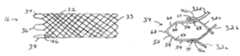
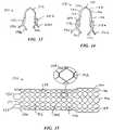
- FIG. 16is a side view of a further alternative embodiment prosthesis with welded loops at both ends.
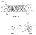
- FIG. 17illustrates a component for positionally adjusting or retrieving the stent of FIG. 16 after its deployment.
- FIG. 1a stent 16 fabricated according to the present invention, and part of a device 18 used to intraluminally deliver the stent to an intended treatment site and deploy the stent at the treatment site.
- the deviceincludes an elongate, flexible outer catheter 20 having a distal end region 22 , along which the outer catheter surrounds stent 16 and maintains the stent in a reduced-radius, axially elongated delivery state to facilitate an intraluminal delivery of the stent to the treatment site.
- Stent 16is contained within a lumen 24 , which runs substantially the entire length of the outer catheter.
- An inner catheter 26contained in the lumen, extends lengthwise along the outer catheter and is moveable axially relative to the outer catheter.
- a deployment member 28is fixed to inner catheter 26 , proximally of stent 16 .
- Inner catheter 26includes a lumen (not shown) to accommodate a guidewire 30 , which is used to guide the inner and outer catheters to the treatment site.
- Stent 16is composed of oppositely directed helically wound strands or filaments 32 that intersect one another to form multiple intersections or crossing points.
- Strands 32are interbraided in a one-over-one-under pattern.
- strands 32are bent to form distal end loops 33 .
- the strandsare formed of a superelastic alloy of titanium and nickel sold under the brand name Nitinol.
- suitable strand materialsinclude cobalt-based alloys such as those sold under the brand names Elgiloy or Phynox, MP35N alloy, and certain stainless steels.
- Suitable nonmetallic alternativesinclude polymers, for example polyester and polyethylene terephthalate (PET).
- Strands 32are resilient, and when maintained as shown in FIG. 1 store an elastic restoring force.
- stent 16When released from outer catheter 20 , stent 16 self-expands under the restoring force, toward a normal or relaxed state shown in FIG. 5 that stent 16 assumes when under no external stress.
- stent 16shortens axially as it expands radially.
- stent 16engages surrounding tissue before it expands fully to the relaxed state.
- the deployed stentexerts a radially outward force against the tissue that tends to anchor the stent at the treatment site.
- One of the challenges to the physician using device 18is to accurately place the stent. Accurate placement is made more difficult by the axial shortening of the stent as it enlarges radially. Once the stent is fully deployed, it is contiguous with and frequently partially embedded into the surrounding tissue. As a result, it is difficult to adjust the position of the stent to correct a less than accurate placement. With prostheses constructed as shown in FIGS. 1-3 , proximal stent adjustment is particularly difficult because of the stiff welded and/or twisted strand couplings with abrupt proximal ends that present the risk of injury to tissue.
- the proximal end of stent 16is formed with a series of loop segments. Specifically, six loop segments 34 - 44 are formed in conjunction with twelve strand junctions or couplings 46 . Each loop segment acts as a closure member, cooperating with its associated pair of strand couplings and the coupled strands to form a closed loop end termination. Each loop segment is formed with an extension of one of the coupled strands. For example, FIG. 6 shows a strand junction 46 a including strands 32 a and 32 b , coupled to each other by a weld 48 . Similarly, strands 32 c and 32 d are joined by a weld 50 to form a strand junction 46 b.
- Strand 32 bis longer than the other strands by a predetermined length, to provide a proximal strand extension or portion 52 extending beyond the other strands, which is shaped to provide loop segment 34 .
- Loop segment 34has several discrete elements, including opposed axially extending legs 54 and 56 , opposite inclined linear side sections 58 and 60 , a curved proximal end apex 62 , and a pair of arcuate sections 64 and 66 , each between one of the legs and side sections.
- a portion of leg 56is axially aligned with junction 46 b , and is connected to that coupling by a weld 68 .
- the remaining loop segments 34 - 44are formed in the same manner.
- Stent 16 after deploymentcan be moved proximally along the body lumen without the risk of trauma to the surrounding tissue.
- Apex 62 and its counterparts on the other loop segmentsprovide smooth, rounded, blunt proximal end terminations with no tendency to poke or cut into tissue as the stent is moved.
- the loop segmentsare considerably more flexible than the strand end junctions, regardless of whether the strands are twisted. This is primarily due to strands 32 , which are bendable about tangential axes both proximally and distally of junctions 46 to carry apex 62 and its counterparts radially inward. This affords a localized (proximal) radial contraction of the stent to facilitate pulling the stent proximally along the lumen while the majority of the stent remains in contact with surrounding tissue.
- Apex 62further is bendable about radial axes, to bring the legs and side sections closer to one another during radial contraction.
- Arcuate sections 64 and 66also are bendable about radial axes, although unlike the apex, they bend in the direction of increasing radii of curvature during radial contraction of the stent. As a result, legs 54 and 56 tend to retain their axial orientation during radial contraction of the stent.
- loop segments 34 - 44are arranged symmetrically about the proximal end of the stent, equally angularly spaced apart from one another. Radial contraction of stent 16 not only bends each loop segment into a narrower configuration, but also reduces the gaps between adjacent loop segments. The extent of permitted radial contraction is limited by the amount of bending permitted in each loop segment, particularly at the apex.
- a salient feature of the present inventionis the association of single loop segments with pairs of strand junctions, which reduces the number of loops by one-half, as compared to the conventional loops formed by bending the strands at one end of the stent.
- the proximal end of stent 16is contractible to a smaller diameter.
- Stent 16is fabricated, first by helically winding strands 32 onto a shaping mandrel 70 . While FIG. 8 shows only one strand 32 a wound about the mandrel, it is to be appreciated that all of the strands are wound simultaneously onto the mandrel to form the braided structure. From a first end 72 , strand 32 a is wound helically about mandrel 70 until it approaches a remote end 76 of the mandrel, where the strand is trained about a pin 78 to form one of bends 33 . Then, the strand is wound helically about the mandrel in the opposite direction, to a proximate end 82 .
- Each strandforms two helical runs or passes over the axial length of the stent.
- twelve strandsform twenty-four such runs.
- the ends of the strandsform twelve junctions 46 .
- FIG. 9shows two of the strand junctions, representing four strand ends, disposed on mandrel 70 .
- Strand 32 bincludes portion 52 extending axially beyond the rest of the strands.
- Three pins 84are fixed to the mandrel, axially outwardly of the strand couplings. Extension 52 of strand 32 b is bent about each of pins 84 . Its free end 86 is positioned against strand 32 c , then attached to strand 32 c by welding.
- mandrel 70is placed in an oven (or the mandrel is heated) to a heat the strands to a heat set temperature.
- the heat set temperaturewhile much lower than the melting temperature for the strand material, is sufficient to relax the strands such that they are amenable to shaping.
- each strandretains its helical shape, and the strands cooperate to determine the relaxed-state tubular shape of the braided structure.
- Shape memory alloyssuch as Nitinol are particularly well suited for this process.
- FIG. 11is a view similar to that in FIG. 6 , showing part of a stent 90 with an alternative loop forming arrangement in which a strand 92 a (rather than 92 b ) is longer than the other strands and provides the loop segment.
- a free end 94 of strand 92 ais positioned adjacent strand 92 d , rather than 92 c , then welded to a junction 96 b as before.
- Thiscan be conveniently considered and “outside-to-outside” connection, as opposed to the “inside-to-inside” connection shown in FIG. 6 .
- outside-to-outside connectionsform slightly wider loop segments.
- FIG. 12shows another alternative arrangement in which hypotubes are used in lieu of welds to secure adjacent portions of the strands.
- the connections for one of the loop segmentsare formed by sliding a hypotube 98 over strands 100 a and 10 b , sliding a hypotube 102 over strands 100 c and 100 d , shaping an extension 104 of strand 100 b and inserting its free end into hypotube 102 , then crimping the hypotubes to provide a friction fit that anchors the strands to one another.
- the hypotubespreferably are formed of steel.
- tubes 98 and 102can be formed of elastomeric materials and provide a friction fit, augmented with an adhesive if desired.
- tubes 98 and 102are heat shrunk onto the adjacent strands.
- FIG. 13shows part of the proximal end of a solymeric stent 106 , specifically polymeric strands 108 a and 108 b forming a junction 110 a , and polymeric strands 108 c and 108 d forming a junction 110 b .
- the strand junctionsare formed by fusion bonding.
- an extension 112 of strand 108 bis shaped to provide a loop segment, and its free end is connected to strand 108 c , again by fusion bonding.
- the fusion bondsare preferably formed simultaneously, although they can be formed serially.
- FIG. 14illustrates a proximal end region of an alternative stent 114 in which strands 116 a and 116 b are welded to form a strand coupling 118 a , and strands 116 and 116 d are welded into a strand coupling 118 b . None of strands 116 a - d extends axially beyond the others. Thus, none of strands 116 is shaped to provide end closure. Instead, loop closure is provided by a generally U-shaped strand segment 120 .
- the strand segmentincludes counterparts to the elements described in connection with loop segment 34 a , including opposed legs 122 and 124 , side sections 126 and 128 , an apex 130 , and arcuate sections 132 and 134 .
- Strand segment 120is attached to strand couplings 118 a and 118 b , by any of the previously mentioned connecting methods. This approach requires connections at both strand couplings. However, it facilitates using different materials for strands 116 and for strand segments 120 if desired, and also allows attachment of the strand segments to a previously formed stent.
- FIG. 15illustrates an alternative embodiment open-frame prosthesis 136 , in which elongate strands 138 are wound about a mandrel to form multiple, generally hexagonal cells 140 . As indicated in the enlargement, adjacent cells are joined by coextensive regions 142 along which strands 138 are twisted helically about one another. At a distal end 144 of the prosthesis, the strands are bent to provide loops 146 . A plurality of radiopaque markers 148 are fixed to the loops.
- pairs of strands 138are welded together to form strand couplings.
- Each pair of adjacent couplingsincludes one strand with an extended portion shaped into a loop segment 152 , which in turn is welded to the adjacent strand coupling of the pair.
- Radiopaque markers 153are fixed near loop segments 152 , and may be fixed to the loop segments.
- Strands 138form multiple intersections 154 in addition to coextensive regions 142 .
- Loop segments 152can be arcuate as shown, or be shaped to more closely resemble loop segments 34 - 44 .
- FIG. 16shows a braided prosthesis 156 formed of two sets of oppositely directed helically wound strands 158 . At both ends of prosthesis 156 , pairs of the strands are welded or otherwise secured together to form proximal end strand couplings 160 , and distal end strand couplings 162 .
- the prosthesisincludes a plurality of proximal end loop segments 164 . Each loop segment 164 is connected to an associated pair of the strand couplings 160 .
- Prosthesis 156includes a plurality of distal end loop segments 166 , each coupled to an associated pair of the distal end strand couplings.
- FIG. 17illustrates a proximal end region of prosthesis 156 , and a positioning device 168 spaced apart proximally from the prosthesis.
- Device 168includes an elongate flexible shaft 170 , a distal portion of which is shown.
- a tine 172 at the distal end of shaft 170extends away from the shaft, inclined proximally and radially outward.
- prosthesis 156may be pulled proximally, which causes localized axial elongation.
- the axial elongationradially contracts prosthesis 156 along its proximal end region near the loop segments. This facilitates proximal movement of the prosthesis by pulling the prosthesis radially inward at least slightly away from the surrounding tissue.
- the frictional holdis overcome and the entire prosthesis moves proximally, although a distal portion of the prosthesis may remain engaged with surrounding tissue. This is beneficial, in that the fictional “drag” allows a more incremental, accurate adjustment of prosthesis position.
- device 168can be replaced with a device with several tines or shafts, to simultaneously pull several, or all, of the loop segments.
- a tethercan be threaded through loop segments 164 , such that proximally pulling the tether brings the loop segments radially inward and closer together in cinch fashion.
- device 168 or the aforementioned tethercan be used not only for incremental proximal adjustments, but for retrieval of prosthesis 156 .
- a device similar to device 168with a tine preferably inclined radially outwardly in the distal direction, could be used to engage one of distal end loop segments 166 .
- loop segmentsare attached to associated pairs of strand end couplings to reduce the risk of trauma to tissue, and provide a prosthesis that is radially compressible to a smaller diameter to facilitate intraluminal delivery.
- the looped endseliminate the potential for adjacent twisted strand pairs to interlock when the prosthesis is compressed to its delivery state, ensuring a more reliable radial expansion of the prosthesis when deployed at the treatment site.
- the looped endsfurther facilitate incremental repositioning of the prosthesis after its deployment.
Landscapes
- Health & Medical Sciences (AREA)
- Engineering & Computer Science (AREA)
- Biomedical Technology (AREA)
- Textile Engineering (AREA)
- Life Sciences & Earth Sciences (AREA)
- Public Health (AREA)
- Heart & Thoracic Surgery (AREA)
- Vascular Medicine (AREA)
- Oral & Maxillofacial Surgery (AREA)
- Animal Behavior & Ethology (AREA)
- General Health & Medical Sciences (AREA)
- Transplantation (AREA)
- Veterinary Medicine (AREA)
- Cardiology (AREA)
- Manufacturing & Machinery (AREA)
- Prostheses (AREA)
- Media Introduction/Drainage Providing Device (AREA)
- Massaging Devices (AREA)
Abstract
Description
Claims (22)
Priority Applications (5)
| Application Number | Priority Date | Filing Date | Title |
|---|---|---|---|
| US10/852,495US7655039B2 (en) | 2003-05-23 | 2004-05-24 | Stents with attached looped ends |
| US12/649,843US8109988B2 (en) | 2003-05-23 | 2009-12-30 | Stents with attached looped ends |
| US13/339,756US20120101564A1 (en) | 2003-05-23 | 2011-12-29 | Stents with attached looped ends |
| US14/084,098US9788979B2 (en) | 2003-05-23 | 2013-11-19 | Stents with attached looped ends |
| US15/702,359US10426643B2 (en) | 2003-05-23 | 2017-09-12 | Stents with attached looped ends |
Applications Claiming Priority (2)
| Application Number | Priority Date | Filing Date | Title |
|---|---|---|---|
| US47292903P | 2003-05-23 | 2003-05-23 | |
| US10/852,495US7655039B2 (en) | 2003-05-23 | 2004-05-24 | Stents with attached looped ends |
Related Child Applications (1)
| Application Number | Title | Priority Date | Filing Date |
|---|---|---|---|
| US12/649,843ContinuationUS8109988B2 (en) | 2003-05-23 | 2009-12-30 | Stents with attached looped ends |
Publications (2)
| Publication Number | Publication Date |
|---|---|
| US20050049682A1 US20050049682A1 (en) | 2005-03-03 |
| US7655039B2true US7655039B2 (en) | 2010-02-02 |
Family
ID=33490539
Family Applications (5)
| Application Number | Title | Priority Date | Filing Date |
|---|---|---|---|
| US10/852,495Active2027-01-17US7655039B2 (en) | 2003-05-23 | 2004-05-24 | Stents with attached looped ends |
| US12/649,843Expired - LifetimeUS8109988B2 (en) | 2003-05-23 | 2009-12-30 | Stents with attached looped ends |
| US13/339,756AbandonedUS20120101564A1 (en) | 2003-05-23 | 2011-12-29 | Stents with attached looped ends |
| US14/084,098Expired - LifetimeUS9788979B2 (en) | 2003-05-23 | 2013-11-19 | Stents with attached looped ends |
| US15/702,359Expired - LifetimeUS10426643B2 (en) | 2003-05-23 | 2017-09-12 | Stents with attached looped ends |
Family Applications After (4)
| Application Number | Title | Priority Date | Filing Date |
|---|---|---|---|
| US12/649,843Expired - LifetimeUS8109988B2 (en) | 2003-05-23 | 2009-12-30 | Stents with attached looped ends |
| US13/339,756AbandonedUS20120101564A1 (en) | 2003-05-23 | 2011-12-29 | Stents with attached looped ends |
| US14/084,098Expired - LifetimeUS9788979B2 (en) | 2003-05-23 | 2013-11-19 | Stents with attached looped ends |
| US15/702,359Expired - LifetimeUS10426643B2 (en) | 2003-05-23 | 2017-09-12 | Stents with attached looped ends |
Country Status (9)
| Country | Link |
|---|---|
| US (5) | US7655039B2 (en) |
| EP (2) | EP1628596B1 (en) |
| JP (1) | JP4791364B2 (en) |
| AT (1) | ATE504272T1 (en) |
| AU (1) | AU2004243014B2 (en) |
| CA (1) | CA2526382C (en) |
| DE (1) | DE602004032127D1 (en) |
| ES (1) | ES2364555T3 (en) |
| WO (1) | WO2004105647A1 (en) |
Cited By (26)
| Publication number | Priority date | Publication date | Assignee | Title |
|---|---|---|---|---|
| US20050256563A1 (en)* | 2004-05-14 | 2005-11-17 | Scimed Life Systems, Inc. | Method for reducing stent weld profiles and a stent having reduced weld profiles and a closed-end wire configuration |
| US20090054972A1 (en)* | 2004-11-10 | 2009-02-26 | Boston Scientific, Scimed, Inc. | Atraumatic stent with reduced deployment force, method for making the same and method and apparatus for deploying and positioning the stent |
| US20110082483A1 (en)* | 2009-10-01 | 2011-04-07 | Cardioniti | Cutting balloon assembly and method of manufacturing thereof |
| US8337543B2 (en) | 2004-11-05 | 2012-12-25 | Boston Scientific Scimed, Inc. | Prosthesis anchoring and deploying device |
| US8414635B2 (en) | 1999-02-01 | 2013-04-09 | Idev Technologies, Inc. | Plain woven stents |
| US8419788B2 (en) | 2006-10-22 | 2013-04-16 | Idev Technologies, Inc. | Secured strand end devices |
| US8475372B2 (en) | 2010-10-29 | 2013-07-02 | Medtronic Vascular, Inc. | Implantable medical sensor and fixation system |
| WO2014011330A1 (en) | 2012-07-13 | 2014-01-16 | Boston Scientific Scimed, Inc. | Collapsible caged-ball prosthetic valve for transcatheter delivery and method of use |
| US8727996B2 (en) | 2011-04-20 | 2014-05-20 | Medtronic Vascular, Inc. | Delivery system for implantable medical device |
| US8864676B2 (en) | 2010-10-29 | 2014-10-21 | Medtronic Vascular, Inc. | Implantable medical sensor and fixation system |
| US8876881B2 (en) | 2006-10-22 | 2014-11-04 | Idev Technologies, Inc. | Devices for stent advancement |
| US9023095B2 (en) | 2010-05-27 | 2015-05-05 | Idev Technologies, Inc. | Stent delivery system with pusher assembly |
| US9155643B2 (en) | 2010-04-30 | 2015-10-13 | Boston Scientific Scimed, Inc. | Apparatus and method for manufacturing a single wire stent |
| WO2015135658A3 (en)* | 2014-03-13 | 2015-12-10 | Klaus Düring | Compressible self-expandable stent for splinting and/or keeping open a cavity, an organ duct, and/or a vessel in the human or animal body |
| US9351648B2 (en) | 2012-08-24 | 2016-05-31 | Medtronic, Inc. | Implantable medical device electrode assembly |
| US10004617B2 (en) | 2015-10-20 | 2018-06-26 | Cook Medical Technologies Llc | Woven stent device and manufacturing method |
| US10213327B2 (en) | 2000-08-17 | 2019-02-26 | Angiomed Gmbh & Co. Medizintechnik Kg | Implant with attached element and method of making such an implant |
| US10231854B2 (en) | 2006-05-18 | 2019-03-19 | C. R. Bard, Inc. | Bend-capable stent prosthesis |
| WO2019164803A1 (en) | 2018-02-20 | 2019-08-29 | Boston Scientific Scimed, Inc. | Drainage device |
| US10470904B2 (en) | 2016-05-18 | 2019-11-12 | Boston Scientific Scimed, Inc. | Stent retrieval system |
| US10500075B2 (en) | 2006-11-10 | 2019-12-10 | C. R. Bard, Inc. | Stent |
| US10568754B2 (en) | 2016-05-13 | 2020-02-25 | Boston Scientific Scimed, Inc. | Protective apparatus for use in gastrointestinal tract |
| US10849770B2 (en) | 2006-05-17 | 2020-12-01 | C. R. Bard, Inc. | Bend-capable tubular prosthesis |
| US20210282948A1 (en)* | 2015-09-18 | 2021-09-16 | Terumo Corporation | Vessel Prosthesis |
| US11278701B2 (en) | 2016-10-13 | 2022-03-22 | Lake Region Manufacturing, Inc. | Apparatus including multiple joined hypotubes and method of making same |
| US11304795B2 (en) | 2017-10-25 | 2022-04-19 | Boston Scientific Scimed, Inc. | Stent with atraumatic spacer |
Families Citing this family (52)
| Publication number | Priority date | Publication date | Assignee | Title |
|---|---|---|---|---|
| US9301862B2 (en) | 2005-01-28 | 2016-04-05 | Boston Scientific Scimed, Inc. | Stent retrieval member and devices and methods for retrieving or repositioning a stent |
| EP1887974B1 (en) | 2005-05-13 | 2018-04-25 | Boston Scientific Limited | Integrated stent repositioning and retrieval loop |
| GB0512320D0 (en)* | 2005-06-16 | 2005-07-27 | Angiomed Ag | Catheter device FLEXX tube |
| GB0512319D0 (en) | 2005-06-16 | 2005-07-27 | Angiomed Ag | Catheter device variable pusher |
| US7279664B2 (en)* | 2005-07-26 | 2007-10-09 | Boston Scientific Scimed, Inc. | Resonator for medical device |
| US20070250148A1 (en)* | 2005-09-26 | 2007-10-25 | Perry Kenneth E Jr | Systems, apparatus and methods related to helical, non-helical or removable stents with rectilinear ends |
| DE102005050386A1 (en)* | 2005-10-20 | 2007-04-26 | Campus Gmbh & Co. Kg | Temporary stent which can be deposited in a body vial |
| GB0613670D0 (en)* | 2006-07-10 | 2006-08-16 | Angiomed Ag | Tubular metal prosthesis and method of making it |
| GB0616729D0 (en)* | 2006-08-23 | 2006-10-04 | Angiomed Ag | Method of welding a component to a shape memory alloy workpiece |
| GB0616999D0 (en)* | 2006-08-29 | 2006-10-04 | Angiomed Ag | Annular mesh |
| EP2063824B1 (en)* | 2006-09-07 | 2020-10-28 | Angiomed GmbH & Co. Medizintechnik KG | Helical implant having different ends |
| GB0624419D0 (en)* | 2006-12-06 | 2007-01-17 | Angiomed Ag | Stenting ring with marker |
| GB0703379D0 (en)* | 2007-02-21 | 2007-03-28 | Angiomed Ag | Stent with radiopaque marker |
| GB0706499D0 (en) | 2007-04-03 | 2007-05-09 | Angiomed Ag | Bendable stent |
| US8409270B2 (en)* | 2007-04-16 | 2013-04-02 | Boston Scientific Scimed, Inc. | Radiopaque compositions, stents and methods of preparation |
| WO2009003049A2 (en) | 2007-06-25 | 2008-12-31 | Micro Vention, Inc. | Self-expanding prosthesis |
| GB0717481D0 (en) | 2007-09-07 | 2007-10-17 | Angiomed Ag | Self-expansible stent with radiopaque markers |
| US9393137B2 (en) | 2007-09-24 | 2016-07-19 | Boston Scientific Scimed, Inc. | Method for loading a stent into a delivery system |
| EP2247264A4 (en)* | 2008-02-29 | 2011-08-31 | Florida Int Univ Board Trustees | MULTI-SHEET ARTIFICIAL CARDIAC VALVE PROSTHESIS FOR CATHETER PLACEMENT, AND INTRAVASCULAR PLACEMENT SYSTEM FOR CARDIAC VALVE PROSTHESIS FOR CATHETER ARRANGEMENT |
| EP2349124B1 (en)* | 2008-09-05 | 2018-10-17 | Cook Medical Technologies LLC | Apparatus for improved stent deployment |
| GB0822106D0 (en)* | 2008-12-03 | 2009-01-07 | Angiomed Ag | Retractable catheter |
| US8151682B2 (en)* | 2009-01-26 | 2012-04-10 | Boston Scientific Scimed, Inc. | Atraumatic stent and method and apparatus for making the same |
| US8357178B2 (en) | 2009-07-08 | 2013-01-22 | Concentric Medical, Inc. | Vascular and bodily duct treatment devices and methods |
| US8357179B2 (en) | 2009-07-08 | 2013-01-22 | Concentric Medical, Inc. | Vascular and bodily duct treatment devices and methods |
| US8795317B2 (en) | 2009-07-08 | 2014-08-05 | Concentric Medical, Inc. | Embolic obstruction retrieval devices and methods |
| US8529596B2 (en) | 2009-07-08 | 2013-09-10 | Concentric Medical, Inc. | Vascular and bodily duct treatment devices and methods |
| US8795345B2 (en) | 2009-07-08 | 2014-08-05 | Concentric Medical, Inc. | Vascular and bodily duct treatment devices and methods |
| EP3081196B1 (en) | 2009-09-21 | 2018-04-18 | Boston Scientific Scimed, Inc. | Integrated stent retrieval loop adapted for snare removal and/or optimized purse stringing |
| EP2485689B1 (en) | 2009-10-09 | 2020-03-18 | Boston Scientific Scimed, Inc. | Stomach bypass |
| US8778011B2 (en)* | 2010-09-30 | 2014-07-15 | Cook Medical Technologies Llc | Soft crowns |
| US8381742B2 (en) | 2011-01-24 | 2013-02-26 | Leonard G. Lorch | Dental floss |
| WO2012106657A2 (en)* | 2011-02-04 | 2012-08-09 | Concentric Medical, Inc. | Vascular and bodily duct treatment devices and methods |
| DE102011011180B4 (en) | 2011-02-14 | 2015-10-01 | Acandis Gmbh & Co. Kg | Medical device with an expandable mesh |
| WO2013052528A1 (en) | 2011-10-04 | 2013-04-11 | Cook Medical Technologies Llc | Reduced wire profile stent |
| DE102012005658B4 (en) | 2012-03-22 | 2013-10-24 | Schott Ag | White light generation |
| CN102988122B (en)* | 2012-11-13 | 2013-11-06 | 浦易(上海)生物技术有限公司 | Prosthetic system for treating nasosinusitis or allergic rhinitis |
| US9610179B2 (en)* | 2013-03-12 | 2017-04-04 | Cook Medical Technologies Llc | Atraumatic stent crowns |
| CN105873547B (en) | 2013-11-08 | 2019-05-03 | 波士顿科学国际有限公司 | intraluminal device |
| KR101922321B1 (en)* | 2014-04-08 | 2018-11-26 | 보스톤 싸이엔티픽 싸이메드 인코포레이티드 | Medical devices and related methods of use thereof |
| WO2015160998A2 (en) | 2014-04-17 | 2015-10-22 | Abbott Cardiovascular Systems Inc. | Coatings for braided medical devices and methods of forming same |
| KR101696810B1 (en)* | 2015-02-04 | 2017-02-01 | 주식회사 엠아이텍 | Stent for connecting adjacent tissues and manufacturing method thereof |
| KR101728319B1 (en)* | 2015-04-15 | 2017-04-19 | 주식회사 엠아이텍 | Methods for Manufacturing Stent |
| BR102015011376B1 (en) | 2015-05-18 | 2023-04-04 | Murilo Pundek Rocha | IMPLANTABLE ARTIFICIAL BRONCHI |
| FR3074040B1 (en)* | 2017-11-27 | 2022-03-04 | Id Nest Medical | OPTIMIZED STRUCTURE FOR AN EXPANDABLE IMPLANT OF THE STENT OR ENDOPROSTHESIS TYPE |
| KR102823520B1 (en) | 2018-04-09 | 2025-06-20 | 보스톤 싸이엔티픽 싸이메드 인코포레이티드 | Stent |
| EP3908233B1 (en) | 2019-01-07 | 2024-08-21 | Boston Scientific Scimed, Inc. | Stent with anti-migration feature |
| USD902407S1 (en)* | 2019-11-19 | 2020-11-17 | Pulmair Medical, Inc. | Implantable artificial bronchus |
| CA3195219A1 (en) | 2020-09-29 | 2022-04-07 | Boston Scientific Scimed, Inc. | Stent with anti-migration features |
| USD954953S1 (en) | 2020-11-03 | 2022-06-14 | Pulmair Medical, Inc. | Implantable artificial bronchus |
| CA3202580A1 (en) | 2020-12-02 | 2022-06-09 | Boston Scientific Scimed, Inc. | Stent with improved deployment characteristics |
| WO2022128974A1 (en)* | 2020-12-16 | 2022-06-23 | Koninklijke Philips N.V. | Braided stent |
| USD1014758S1 (en) | 2023-04-19 | 2024-02-13 | Pulmair Medical, Inc. | Implantable artificial bronchus |
Citations (115)
| Publication number | Priority date | Publication date | Assignee | Title |
|---|---|---|---|---|
| US4300244A (en) | 1979-09-19 | 1981-11-17 | Carbomedics, Inc. | Cardiovascular grafts |
| US4512338A (en) | 1983-01-25 | 1985-04-23 | Balko Alexander B | Process for restoring patency to body vessels |
| US4553545A (en) | 1981-09-16 | 1985-11-19 | Medinvent S.A. | Device for application in blood vessels or other difficultly accessible locations and its use |
| US4572186A (en) | 1983-12-07 | 1986-02-25 | Cordis Corporation | Vessel dilation |
| US4580568A (en) | 1984-10-01 | 1986-04-08 | Cook, Incorporated | Percutaneous endovascular stent and method for insertion thereof |
| US4665918A (en) | 1986-01-06 | 1987-05-19 | Garza Gilbert A | Prosthesis system and method |
| US4665771A (en) | 1984-10-15 | 1987-05-19 | Mitchell Frank R | Hypocyclic drive |
| US4681110A (en) | 1985-12-02 | 1987-07-21 | Wiktor Dominik M | Catheter arrangement having a blood vessel liner, and method of using it |
| US4732152A (en) | 1984-12-05 | 1988-03-22 | Medinvent S.A. | Device for implantation and a method of implantation in a vessel using such device |
| US4733665A (en) | 1985-11-07 | 1988-03-29 | Expandable Grafts Partnership | Expandable intraluminal graft, and method and apparatus for implanting an expandable intraluminal graft |
| US4740207A (en) | 1986-09-10 | 1988-04-26 | Kreamer Jeffry W | Intralumenal graft |
| US4762128A (en) | 1986-12-09 | 1988-08-09 | Advanced Surgical Intervention, Inc. | Method and apparatus for treating hypertrophy of the prostate gland |
| US4768507A (en) | 1986-02-24 | 1988-09-06 | Medinnovations, Inc. | Intravascular stent and percutaneous insertion catheter system for the dilation of an arterial stenosis and the prevention of arterial restenosis |
| US4795458A (en) | 1987-07-02 | 1989-01-03 | Regan Barrie F | Stent for use following balloon angioplasty |
| US4830003A (en) | 1988-06-17 | 1989-05-16 | Wolff Rodney G | Compressive stent and delivery system |
| US4848343A (en) | 1986-10-31 | 1989-07-18 | Medinvent S.A. | Device for transluminal implantation |
| US4875480A (en) | 1986-09-30 | 1989-10-24 | Medinvent S.A. | Device for transluminal implantation |
| US4878906A (en) | 1986-03-25 | 1989-11-07 | Servetus Partnership | Endoprosthesis for repairing a damaged vessel |
| US4886062A (en) | 1987-10-19 | 1989-12-12 | Medtronic, Inc. | Intravascular radially expandable stent and method of implant |
| US4893623A (en) | 1986-12-09 | 1990-01-16 | Advanced Surgical Intervention, Inc. | Method and apparatus for treating hypertrophy of the prostate gland |
| US4907336A (en) | 1987-03-13 | 1990-03-13 | Cook Incorporated | Method of making an endovascular stent and delivery system |
| US4913141A (en) | 1988-10-25 | 1990-04-03 | Cordis Corporation | Apparatus and method for placement of a stent within a subject vessel |
| US4950227A (en) | 1988-11-07 | 1990-08-21 | Boston Scientific Corporation | Stent delivery system |
| US4969458A (en) | 1987-07-06 | 1990-11-13 | Medtronic, Inc. | Intracoronary stent and method of simultaneous angioplasty and stent implant |
| US4969890A (en) | 1987-07-10 | 1990-11-13 | Nippon Zeon Co., Ltd. | Catheter |
| US4990155A (en) | 1989-05-19 | 1991-02-05 | Wilkoff Howard M | Surgical stent method and apparatus |
| US4998539A (en) | 1987-12-18 | 1991-03-12 | Delsanti Gerard L | Method of using removable endo-arterial devices to repair detachments in the arterial walls |
| US5002560A (en) | 1989-09-08 | 1991-03-26 | Advanced Cardiovascular Systems, Inc. | Expandable cage catheter with a rotatable guide |
| US5026377A (en) | 1989-07-13 | 1991-06-25 | American Medical Systems, Inc. | Stent placement instrument and method |
| US5034001A (en) | 1989-09-08 | 1991-07-23 | Advanced Cardiovascular Systems, Inc. | Method of repairing a damaged blood vessel with an expandable cage catheter |
| US5035706A (en)* | 1989-10-17 | 1991-07-30 | Cook Incorporated | Percutaneous stent and method for retrieval thereof |
| US5037427A (en) | 1987-03-25 | 1991-08-06 | Terumo Kabushiki Kaisha | Method of implanting a stent within a tubular organ of a living body and of removing same |
| US5037392A (en) | 1989-06-06 | 1991-08-06 | Cordis Corporation | Stent-implanting balloon assembly |
| US5041126A (en) | 1987-03-13 | 1991-08-20 | Cook Incorporated | Endovascular stent and delivery system |
| US5059166A (en) | 1989-12-11 | 1991-10-22 | Medical Innovative Technologies R & D Limited Partnership | Intra-arterial stent with the capability to inhibit intimal hyperplasia |
| US5061275A (en) | 1986-04-21 | 1991-10-29 | Medinvent S.A. | Self-expanding prosthesis |
| US5064435A (en) | 1990-06-28 | 1991-11-12 | Schneider (Usa) Inc. | Self-expanding prosthesis having stable axial length |
| US5071407A (en) | 1990-04-12 | 1991-12-10 | Schneider (U.S.A.) Inc. | Radially expandable fixation member |
| US5078720A (en) | 1990-05-02 | 1992-01-07 | American Medical Systems, Inc. | Stent placement instrument and method |
| US5089005A (en) | 1987-08-13 | 1992-02-18 | Terumo Kabushiki Kaisha | Catheter for the introduction of an expandable member |
| US5089006A (en) | 1989-11-29 | 1992-02-18 | Stiles Frank B | Biological duct liner and installation catheter |
| US5092877A (en) | 1988-09-01 | 1992-03-03 | Corvita Corporation | Radially expandable endoprosthesis |
| US5108416A (en) | 1990-02-13 | 1992-04-28 | C. R. Bard, Inc. | Stent introducer system |
| US5123917A (en) | 1990-04-27 | 1992-06-23 | Lee Peter Y | Expandable intraluminal vascular graft |
| US5135517A (en) | 1990-07-19 | 1992-08-04 | Catheter Research, Inc. | Expandable tube-positioning apparatus |
| US5158548A (en) | 1990-04-25 | 1992-10-27 | Advanced Cardiovascular Systems, Inc. | Method and system for stent delivery |
| US5163952A (en) | 1990-09-14 | 1992-11-17 | Michael Froix | Expandable polymeric stent with memory and delivery apparatus and method |
| US5163958A (en) | 1989-02-02 | 1992-11-17 | Cordis Corporation | Carbon coated tubular endoprosthesis |
| US5171262A (en) | 1989-06-15 | 1992-12-15 | Cordis Corporation | Non-woven endoprosthesis |
| US5183085A (en) | 1991-09-27 | 1993-02-02 | Hans Timmermans | Method and apparatus for compressing a stent prior to insertion |
| US5192297A (en) | 1991-12-31 | 1993-03-09 | Medtronic, Inc. | Apparatus and method for placement and implantation of a stent |
| US5197978A (en) | 1991-04-26 | 1993-03-30 | Advanced Coronary Technology, Inc. | Removable heat-recoverable tissue supporting device |
| US5201757A (en) | 1992-04-03 | 1993-04-13 | Schneider (Usa) Inc. | Medial region deployment of radially self-expanding stents |
| US5222971A (en) | 1990-10-09 | 1993-06-29 | Scimed Life Systems, Inc. | Temporary stent and methods for use and manufacture |
| US5222969A (en) | 1992-03-16 | 1993-06-29 | Rolando Gillis | Intravascular stent for cardiovascular intervention |
| US5226913A (en) | 1988-09-01 | 1993-07-13 | Corvita Corporation | Method of making a radially expandable prosthesis |
| US5234457A (en) | 1991-10-09 | 1993-08-10 | Boston Scientific Corporation | Impregnated stent |
| US5242451A (en) | 1987-09-24 | 1993-09-07 | Terumo Kabushiki Kaisha | Instrument for retaining inner diameter of tubular organ lumen |
| US5256146A (en) | 1991-10-11 | 1993-10-26 | W. D. Ensminger | Vascular catheterization system with catheter anchoring feature |
| US5258020A (en) | 1990-09-14 | 1993-11-02 | Michael Froix | Method of using expandable polymeric stent with memory |
| US5263964A (en) | 1992-05-06 | 1993-11-23 | Coil Partners Ltd. | Coaxial traction detachment apparatus and method |
| US5282823A (en) | 1992-03-19 | 1994-02-01 | Medtronic, Inc. | Intravascular radially expandable stent |
| US5282824A (en) | 1990-10-09 | 1994-02-01 | Cook, Incorporated | Percutaneous stent assembly |
| US5290295A (en) | 1992-07-15 | 1994-03-01 | Querals & Fine, Inc. | Insertion tool for an intraluminal graft procedure |
| US5304200A (en) | 1991-05-29 | 1994-04-19 | Cordis Corporation | Welded radially expandable endoprosthesis and the like |
| US5306294A (en) | 1992-08-05 | 1994-04-26 | Ultrasonic Sensing And Monitoring Systems, Inc. | Stent construction of rolled configuration |
| US5354308A (en) | 1992-05-01 | 1994-10-11 | Beth Israel Hospital Association | Metal wire stent |
| US5354309A (en) | 1991-10-11 | 1994-10-11 | Angiomed Ag | Apparatus for widening a stenosis in a body cavity |
| US5372600A (en) | 1991-10-31 | 1994-12-13 | Instent Inc. | Stent delivery systems |
| US5378239A (en) | 1990-04-12 | 1995-01-03 | Schneider (Usa) Inc. | Radially expandable fixation member constructed of recovery metal |
| US5395390A (en)* | 1992-05-01 | 1995-03-07 | The Beth Israel Hospital Association | Metal wire stent |
| US5403341A (en) | 1994-01-24 | 1995-04-04 | Solar; Ronald J. | Parallel flow endovascular stent and deployment apparatus therefore |
| US5405377A (en) | 1992-02-21 | 1995-04-11 | Endotech Ltd. | Intraluminal stent |
| US5411552A (en) | 1990-05-18 | 1995-05-02 | Andersen; Henning R. | Valve prothesis for implantation in the body and a catheter for implanting such valve prothesis |
| US5411507A (en) | 1993-01-08 | 1995-05-02 | Richard Wolf Gmbh | Instrument for implanting and extracting stents |
| US5415664A (en) | 1994-03-30 | 1995-05-16 | Corvita Corporation | Method and apparatus for introducing a stent or a stent-graft |
| US5453090A (en) | 1994-03-01 | 1995-09-26 | Cordis Corporation | Method of stent delivery through an elongate softenable sheath |
| US5456694A (en) | 1994-05-13 | 1995-10-10 | Stentco, Inc. | Device for delivering and deploying intraluminal devices |
| US5474563A (en) | 1993-03-25 | 1995-12-12 | Myler; Richard | Cardiovascular stent and retrieval apparatus |
| US5478349A (en) | 1994-04-28 | 1995-12-26 | Boston Scientific Corporation | Placement of endoprostheses and stents |
| US5484444A (en) | 1992-10-31 | 1996-01-16 | Schneider (Europe) A.G. | Device for the implantation of self-expanding endoprostheses |
| US5507771A (en) | 1992-06-15 | 1996-04-16 | Cook Incorporated | Stent assembly |
| US5522883A (en) | 1995-02-17 | 1996-06-04 | Meadox Medicals, Inc. | Endoprosthesis stent/graft deployment system |
| US5534007A (en) | 1995-05-18 | 1996-07-09 | Scimed Life Systems, Inc. | Stent deployment catheter with collapsible sheath |
| US5554181A (en) | 1994-05-04 | 1996-09-10 | Regents Of The University Of Minnesota | Stent |
| US5591230A (en) | 1994-09-07 | 1997-01-07 | Global Therapeutics, Inc. | Radially expandable stent |
| US5690643A (en) | 1996-02-20 | 1997-11-25 | Leocor, Incorporated | Stent delivery system |
| US5702364A (en) | 1988-02-29 | 1997-12-30 | Scimed Life Systems Inc | Fixed-wire dilatation balloon catheter |
| US5716393A (en) | 1994-05-26 | 1998-02-10 | Angiomed Gmbh & Co. Medizintechnik Kg | Stent with an end of greater diameter than its main body |
| US5772669A (en) | 1996-09-27 | 1998-06-30 | Scimed Life Systems, Inc. | Stent deployment catheter with retractable sheath |
| US5800519A (en) | 1994-04-29 | 1998-09-01 | Kopin Corporation | Tubular medical prosthesis for use in a body lumen |
| US5807327A (en) | 1995-12-08 | 1998-09-15 | Ethicon, Inc. | Catheter assembly |
| US5824041A (en) | 1994-06-08 | 1998-10-20 | Medtronic, Inc. | Apparatus and methods for placement and repositioning of intraluminal prostheses |
| US5833707A (en) | 1995-07-05 | 1998-11-10 | Advanced Cardiovascular Systems, Inc. | Removable stent and method of deployment |
| US5836965A (en) | 1994-10-19 | 1998-11-17 | Jendersee; Brad | Stent delivery and deployment method |
| US5935135A (en) | 1995-09-29 | 1999-08-10 | United States Surgical Corporation | Balloon delivery system for deploying stents |
| US5948017A (en) | 1997-10-12 | 1999-09-07 | Taheri; Syde A. | Modular graft assembly |
| US5954729A (en) | 1991-06-14 | 1999-09-21 | Schneider (Usa) Inc. | Transluminal implantation device |
| US6001123A (en) | 1994-04-01 | 1999-12-14 | Gore Enterprise Holdings Inc. | Folding self-expandable intravascular stent-graft |
| US6007574A (en)* | 1993-12-28 | 1999-12-28 | Pulnev; Sergei Appolonovich | Stent |
| US6027529A (en) | 1997-04-15 | 2000-02-22 | Schneider (Usa) Inc | Protheses with selectively welded crossing strands |
| US6077295A (en) | 1996-07-15 | 2000-06-20 | Advanced Cardiovascular Systems, Inc. | Self-expanding stent delivery system |
| US6102940A (en) | 1998-02-25 | 2000-08-15 | Legona Anstalt | Device forming an endoluminal intracorporeal endoprosthesis, in particular for the abdominal aorta |
| US6120522A (en) | 1998-08-27 | 2000-09-19 | Scimed Life Systems, Inc. | Self-expanding stent delivery catheter |
| US6241757B1 (en) | 1997-02-04 | 2001-06-05 | Solco Surgical Instrument Co., Ltd. | Stent for expanding body's lumen |
| US20010007082A1 (en) | 1996-08-23 | 2001-07-05 | Dusbabek Andrew J. | Stent delivery system having stent securement apparatus |
| US6258099B1 (en) | 1999-03-31 | 2001-07-10 | Scimed Life Systems, Inc. | Stent security balloon/balloon catheter |
| US6258098B1 (en) | 1998-05-08 | 2001-07-10 | William N. Taylor | Stent placement and removal system |
| US6264689B1 (en)* | 1998-03-31 | 2001-07-24 | Scimed Life Systems, Incorporated | Low profile medical stent |
| WO2001054614A2 (en) | 2000-01-31 | 2001-08-02 | Advanced Cardiovascular Systems, Inc. | Self-expanding stent with enhanced delivery precision and stent delivery system |
| US6352553B1 (en) | 1995-12-14 | 2002-03-05 | Gore Enterprise Holdings, Inc. | Stent-graft deployment apparatus and method |
| US6468301B1 (en) | 2000-03-27 | 2002-10-22 | Aga Medical Corporation | Repositionable and recapturable vascular stent/graft |
| US6514282B1 (en) | 1999-10-04 | 2003-02-04 | Kanji Inoue | Method of folding transplanting instrument and transplanting instrument |
| US6623518B2 (en) | 2001-02-26 | 2003-09-23 | Ev3 Peripheral, Inc. | Implant delivery system with interlock |
| US20040098099A1 (en)* | 2002-11-15 | 2004-05-20 | Mccullagh Orla | Braided stent and method for its manufacture |
Family Cites Families (18)
| Publication number | Priority date | Publication date | Assignee | Title |
|---|---|---|---|---|
| FR2683449A1 (en)* | 1991-11-08 | 1993-05-14 | Cardon Alain | ENDOPROTHESIS FOR TRANSLUMINAL IMPLANTATION. |
| US5609627A (en)* | 1994-02-09 | 1997-03-11 | Boston Scientific Technology, Inc. | Method for delivering a bifurcated endoluminal prosthesis |
| US5556414A (en)* | 1995-03-08 | 1996-09-17 | Wayne State University | Composite intraluminal graft |
| WO1996036297A1 (en)* | 1995-05-19 | 1996-11-21 | Kanji Inoue | Transplantation instrument, method of bending same and method of transplanting same |
| US5817126A (en)* | 1997-03-17 | 1998-10-06 | Surface Genesis, Inc. | Compound stent |
| JP4583597B2 (en)* | 1998-05-05 | 2010-11-17 | ボストン サイエンティフィック リミテッド | Smooth end stent |
| US7018401B1 (en)* | 1999-02-01 | 2006-03-28 | Board Of Regents, The University Of Texas System | Woven intravascular devices and methods for making the same and apparatus for delivery of the same |
| US6368346B1 (en)* | 1999-06-03 | 2002-04-09 | American Medical Systems, Inc. | Bioresorbable stent |
| US6585758B1 (en)* | 1999-11-16 | 2003-07-01 | Scimed Life Systems, Inc. | Multi-section filamentary endoluminal stent |
| US6398807B1 (en)* | 2000-01-31 | 2002-06-04 | Scimed Life Systems, Inc. | Braided branching stent, method for treating a lumen therewith, and process for manufacture therefor |
| US20030074051A1 (en)* | 2001-10-16 | 2003-04-17 | Kirsten Freislinger Luehrs | Flexible stent |
| US20040111147A1 (en)* | 2002-12-03 | 2004-06-10 | Rabkin Dmitry J. | Temporary, repositionable or retrievable intraluminal devices |
| DE10233085B4 (en)* | 2002-07-19 | 2014-02-20 | Dendron Gmbh | Stent with guide wire |
| CA2495155A1 (en)* | 2002-08-15 | 2004-02-26 | Gmp Cardiac Care, Inc. | Stent-graft with rails |
| US7179286B2 (en)* | 2003-02-21 | 2007-02-20 | Boston Scientific Scimed, Inc. | Stent with stepped connectors |
| US20040186549A1 (en)* | 2003-03-19 | 2004-09-23 | Swaminathan Jayaraman | Braided stent with looped ends and method for making same |
| US7993387B2 (en)* | 2004-05-14 | 2011-08-09 | Boston Scientific Scimed, Inc. | Stent with reduced weld profiles and a closed-end wire configuration |
| EP1849440A1 (en) | 2006-04-28 | 2007-10-31 | Younes Boudjemline | Vascular stents with varying diameter |
- 2004
- 2004-05-24DEDE602004032127Tpatent/DE602004032127D1/ennot_activeExpired - Lifetime
- 2004-05-24ESES04753163Tpatent/ES2364555T3/ennot_activeExpired - Lifetime
- 2004-05-24JPJP2006533360Apatent/JP4791364B2/ennot_activeExpired - Lifetime
- 2004-05-24ATAT04753163Tpatent/ATE504272T1/ennot_activeIP Right Cessation
- 2004-05-24CACA2526382Apatent/CA2526382C/ennot_activeExpired - Fee Related
- 2004-05-24EPEP04753163Apatent/EP1628596B1/ennot_activeExpired - Lifetime
- 2004-05-24USUS10/852,495patent/US7655039B2/enactiveActive
- 2004-05-24AUAU2004243014Apatent/AU2004243014B2/ennot_activeCeased
- 2004-05-24EPEP10012156.5Apatent/EP2286771B1/ennot_activeExpired - Lifetime
- 2004-05-24WOPCT/US2004/016288patent/WO2004105647A1/enactiveApplication Filing
- 2009
- 2009-12-30USUS12/649,843patent/US8109988B2/ennot_activeExpired - Lifetime
- 2011
- 2011-12-29USUS13/339,756patent/US20120101564A1/ennot_activeAbandoned
- 2013
- 2013-11-19USUS14/084,098patent/US9788979B2/ennot_activeExpired - Lifetime
- 2017
- 2017-09-12USUS15/702,359patent/US10426643B2/ennot_activeExpired - Lifetime
Patent Citations (129)
| Publication number | Priority date | Publication date | Assignee | Title |
|---|---|---|---|---|
| US4300244A (en) | 1979-09-19 | 1981-11-17 | Carbomedics, Inc. | Cardiovascular grafts |
| US4553545A (en) | 1981-09-16 | 1985-11-19 | Medinvent S.A. | Device for application in blood vessels or other difficultly accessible locations and its use |
| US4512338A (en) | 1983-01-25 | 1985-04-23 | Balko Alexander B | Process for restoring patency to body vessels |
| US4572186A (en) | 1983-12-07 | 1986-02-25 | Cordis Corporation | Vessel dilation |
| US4580568A (en) | 1984-10-01 | 1986-04-08 | Cook, Incorporated | Percutaneous endovascular stent and method for insertion thereof |
| US4665771A (en) | 1984-10-15 | 1987-05-19 | Mitchell Frank R | Hypocyclic drive |
| US4732152A (en) | 1984-12-05 | 1988-03-22 | Medinvent S.A. | Device for implantation and a method of implantation in a vessel using such device |
| US4733665A (en) | 1985-11-07 | 1988-03-29 | Expandable Grafts Partnership | Expandable intraluminal graft, and method and apparatus for implanting an expandable intraluminal graft |
| US4733665B1 (en) | 1985-11-07 | 1994-01-11 | Expandable Grafts Partnership | Expandable intraluminal graft,and method and apparatus for implanting an expandable intraluminal graft |
| US4733665C2 (en) | 1985-11-07 | 2002-01-29 | Expandable Grafts Partnership | Expandable intraluminal graft and method and apparatus for implanting an expandable intraluminal graft |
| US4681110A (en) | 1985-12-02 | 1987-07-21 | Wiktor Dominik M | Catheter arrangement having a blood vessel liner, and method of using it |
| US4665918A (en) | 1986-01-06 | 1987-05-19 | Garza Gilbert A | Prosthesis system and method |
| US4768507A (en) | 1986-02-24 | 1988-09-06 | Medinnovations, Inc. | Intravascular stent and percutaneous insertion catheter system for the dilation of an arterial stenosis and the prevention of arterial restenosis |
| US4878906A (en) | 1986-03-25 | 1989-11-07 | Servetus Partnership | Endoprosthesis for repairing a damaged vessel |
| US5061275A (en) | 1986-04-21 | 1991-10-29 | Medinvent S.A. | Self-expanding prosthesis |
| US4740207A (en) | 1986-09-10 | 1988-04-26 | Kreamer Jeffry W | Intralumenal graft |
| US4875480A (en) | 1986-09-30 | 1989-10-24 | Medinvent S.A. | Device for transluminal implantation |
| US4848343A (en) | 1986-10-31 | 1989-07-18 | Medinvent S.A. | Device for transluminal implantation |
| US4762128A (en) | 1986-12-09 | 1988-08-09 | Advanced Surgical Intervention, Inc. | Method and apparatus for treating hypertrophy of the prostate gland |
| US4893623A (en) | 1986-12-09 | 1990-01-16 | Advanced Surgical Intervention, Inc. | Method and apparatus for treating hypertrophy of the prostate gland |
| US4907336A (en) | 1987-03-13 | 1990-03-13 | Cook Incorporated | Method of making an endovascular stent and delivery system |
| US5041126A (en) | 1987-03-13 | 1991-08-20 | Cook Incorporated | Endovascular stent and delivery system |
| US5037427A (en) | 1987-03-25 | 1991-08-06 | Terumo Kabushiki Kaisha | Method of implanting a stent within a tubular organ of a living body and of removing same |
| US4795458A (en) | 1987-07-02 | 1989-01-03 | Regan Barrie F | Stent for use following balloon angioplasty |
| US4969458A (en) | 1987-07-06 | 1990-11-13 | Medtronic, Inc. | Intracoronary stent and method of simultaneous angioplasty and stent implant |
| US4969890A (en) | 1987-07-10 | 1990-11-13 | Nippon Zeon Co., Ltd. | Catheter |
| US5089005A (en) | 1987-08-13 | 1992-02-18 | Terumo Kabushiki Kaisha | Catheter for the introduction of an expandable member |
| US5242451A (en) | 1987-09-24 | 1993-09-07 | Terumo Kabushiki Kaisha | Instrument for retaining inner diameter of tubular organ lumen |
| US4886062A (en) | 1987-10-19 | 1989-12-12 | Medtronic, Inc. | Intravascular radially expandable stent and method of implant |
| US4998539A (en) | 1987-12-18 | 1991-03-12 | Delsanti Gerard L | Method of using removable endo-arterial devices to repair detachments in the arterial walls |
| US5702364A (en) | 1988-02-29 | 1997-12-30 | Scimed Life Systems Inc | Fixed-wire dilatation balloon catheter |
| US4830003A (en) | 1988-06-17 | 1989-05-16 | Wolff Rodney G | Compressive stent and delivery system |
| US5092877A (en) | 1988-09-01 | 1992-03-03 | Corvita Corporation | Radially expandable endoprosthesis |
| US5226913A (en) | 1988-09-01 | 1993-07-13 | Corvita Corporation | Method of making a radially expandable prosthesis |
| US4913141A (en) | 1988-10-25 | 1990-04-03 | Cordis Corporation | Apparatus and method for placement of a stent within a subject vessel |
| US4950227A (en) | 1988-11-07 | 1990-08-21 | Boston Scientific Corporation | Stent delivery system |
| US5163958A (en) | 1989-02-02 | 1992-11-17 | Cordis Corporation | Carbon coated tubular endoprosthesis |
| US4990155A (en) | 1989-05-19 | 1991-02-05 | Wilkoff Howard M | Surgical stent method and apparatus |
| US5037392A (en) | 1989-06-06 | 1991-08-06 | Cordis Corporation | Stent-implanting balloon assembly |
| US5171262A (en) | 1989-06-15 | 1992-12-15 | Cordis Corporation | Non-woven endoprosthesis |
| US5026377A (en) | 1989-07-13 | 1991-06-25 | American Medical Systems, Inc. | Stent placement instrument and method |
| US5034001A (en) | 1989-09-08 | 1991-07-23 | Advanced Cardiovascular Systems, Inc. | Method of repairing a damaged blood vessel with an expandable cage catheter |
| US5002560A (en) | 1989-09-08 | 1991-03-26 | Advanced Cardiovascular Systems, Inc. | Expandable cage catheter with a rotatable guide |
| US5035706A (en)* | 1989-10-17 | 1991-07-30 | Cook Incorporated | Percutaneous stent and method for retrieval thereof |
| US5089006A (en) | 1989-11-29 | 1992-02-18 | Stiles Frank B | Biological duct liner and installation catheter |
| US5059166A (en) | 1989-12-11 | 1991-10-22 | Medical Innovative Technologies R & D Limited Partnership | Intra-arterial stent with the capability to inhibit intimal hyperplasia |
| US5108416A (en) | 1990-02-13 | 1992-04-28 | C. R. Bard, Inc. | Stent introducer system |
| US5071407A (en) | 1990-04-12 | 1991-12-10 | Schneider (U.S.A.) Inc. | Radially expandable fixation member |
| US5378239A (en) | 1990-04-12 | 1995-01-03 | Schneider (Usa) Inc. | Radially expandable fixation member constructed of recovery metal |
| US5496277A (en) | 1990-04-12 | 1996-03-05 | Schneider (Usa) Inc. | Radially expandable body implantable device |
| US5158548A (en) | 1990-04-25 | 1992-10-27 | Advanced Cardiovascular Systems, Inc. | Method and system for stent delivery |
| US5123917A (en) | 1990-04-27 | 1992-06-23 | Lee Peter Y | Expandable intraluminal vascular graft |
| US5078720A (en) | 1990-05-02 | 1992-01-07 | American Medical Systems, Inc. | Stent placement instrument and method |
| US5411552A (en) | 1990-05-18 | 1995-05-02 | Andersen; Henning R. | Valve prothesis for implantation in the body and a catheter for implanting such valve prothesis |
| US5064435A (en) | 1990-06-28 | 1991-11-12 | Schneider (Usa) Inc. | Self-expanding prosthesis having stable axial length |
| US5135517A (en) | 1990-07-19 | 1992-08-04 | Catheter Research, Inc. | Expandable tube-positioning apparatus |
| US5258020A (en) | 1990-09-14 | 1993-11-02 | Michael Froix | Method of using expandable polymeric stent with memory |
| US5163952A (en) | 1990-09-14 | 1992-11-17 | Michael Froix | Expandable polymeric stent with memory and delivery apparatus and method |
| US5222971A (en) | 1990-10-09 | 1993-06-29 | Scimed Life Systems, Inc. | Temporary stent and methods for use and manufacture |
| US5282824A (en) | 1990-10-09 | 1994-02-01 | Cook, Incorporated | Percutaneous stent assembly |
| US5197978B1 (en) | 1991-04-26 | 1996-05-28 | Advanced Coronary Tech | Removable heat-recoverable tissue supporting device |
| US5197978A (en) | 1991-04-26 | 1993-03-30 | Advanced Coronary Technology, Inc. | Removable heat-recoverable tissue supporting device |
| US5304200A (en) | 1991-05-29 | 1994-04-19 | Cordis Corporation | Welded radially expandable endoprosthesis and the like |
| US5954729A (en) | 1991-06-14 | 1999-09-21 | Schneider (Usa) Inc. | Transluminal implantation device |
| US5183085A (en) | 1991-09-27 | 1993-02-02 | Hans Timmermans | Method and apparatus for compressing a stent prior to insertion |
| US5234457A (en) | 1991-10-09 | 1993-08-10 | Boston Scientific Corporation | Impregnated stent |
| US5354309A (en) | 1991-10-11 | 1994-10-11 | Angiomed Ag | Apparatus for widening a stenosis in a body cavity |
| US5256146A (en) | 1991-10-11 | 1993-10-26 | W. D. Ensminger | Vascular catheterization system with catheter anchoring feature |
| US5372600A (en) | 1991-10-31 | 1994-12-13 | Instent Inc. | Stent delivery systems |
| US5192297A (en) | 1991-12-31 | 1993-03-09 | Medtronic, Inc. | Apparatus and method for placement and implantation of a stent |
| US5405377A (en) | 1992-02-21 | 1995-04-11 | Endotech Ltd. | Intraluminal stent |
| US5222969A (en) | 1992-03-16 | 1993-06-29 | Rolando Gillis | Intravascular stent for cardiovascular intervention |
| US5282823A (en) | 1992-03-19 | 1994-02-01 | Medtronic, Inc. | Intravascular radially expandable stent |
| US5443496A (en) | 1992-03-19 | 1995-08-22 | Medtronic, Inc. | Intravascular radially expandable stent |
| US5201757A (en) | 1992-04-03 | 1993-04-13 | Schneider (Usa) Inc. | Medial region deployment of radially self-expanding stents |
| US5354308A (en) | 1992-05-01 | 1994-10-11 | Beth Israel Hospital Association | Metal wire stent |
| US5395390A (en)* | 1992-05-01 | 1995-03-07 | The Beth Israel Hospital Association | Metal wire stent |
| US5263964A (en) | 1992-05-06 | 1993-11-23 | Coil Partners Ltd. | Coaxial traction detachment apparatus and method |
| US5507771A (en) | 1992-06-15 | 1996-04-16 | Cook Incorporated | Stent assembly |
| US5290295A (en) | 1992-07-15 | 1994-03-01 | Querals & Fine, Inc. | Insertion tool for an intraluminal graft procedure |
| US5306294A (en) | 1992-08-05 | 1994-04-26 | Ultrasonic Sensing And Monitoring Systems, Inc. | Stent construction of rolled configuration |
| US5484444A (en) | 1992-10-31 | 1996-01-16 | Schneider (Europe) A.G. | Device for the implantation of self-expanding endoprostheses |
| US5411507A (en) | 1993-01-08 | 1995-05-02 | Richard Wolf Gmbh | Instrument for implanting and extracting stents |
| US5474563A (en) | 1993-03-25 | 1995-12-12 | Myler; Richard | Cardiovascular stent and retrieval apparatus |
| US6309415B1 (en) | 1993-12-28 | 2001-10-30 | Endovascular Technologies, Inc. | Stent |
| US6007574A (en)* | 1993-12-28 | 1999-12-28 | Pulnev; Sergei Appolonovich | Stent |
| US6641608B1 (en) | 1993-12-28 | 2003-11-04 | Endovascular Technologies, Inc. | Method for reconstructing body lumens |
| US5403341A (en) | 1994-01-24 | 1995-04-04 | Solar; Ronald J. | Parallel flow endovascular stent and deployment apparatus therefore |
| US5453090A (en) | 1994-03-01 | 1995-09-26 | Cordis Corporation | Method of stent delivery through an elongate softenable sheath |
| US5415664A (en) | 1994-03-30 | 1995-05-16 | Corvita Corporation | Method and apparatus for introducing a stent or a stent-graft |
| US6017362A (en) | 1994-04-01 | 2000-01-25 | Gore Enterprise Holdings, Inc. | Folding self-expandable intravascular stent |
| US6001123A (en) | 1994-04-01 | 1999-12-14 | Gore Enterprise Holdings Inc. | Folding self-expandable intravascular stent-graft |
| US5478349A (en) | 1994-04-28 | 1995-12-26 | Boston Scientific Corporation | Placement of endoprostheses and stents |
| US6419694B1 (en) | 1994-04-29 | 2002-07-16 | Scimed Life Systems, Inc. | Medical prosthesis |
| US5800519A (en) | 1994-04-29 | 1998-09-01 | Kopin Corporation | Tubular medical prosthesis for use in a body lumen |
| US5554181A (en) | 1994-05-04 | 1996-09-10 | Regents Of The University Of Minnesota | Stent |
| US5456694A (en) | 1994-05-13 | 1995-10-10 | Stentco, Inc. | Device for delivering and deploying intraluminal devices |
| US5716393A (en) | 1994-05-26 | 1998-02-10 | Angiomed Gmbh & Co. Medizintechnik Kg | Stent with an end of greater diameter than its main body |
| US6053941A (en) | 1994-05-26 | 2000-04-25 | Angiomed Gmbh & Co. Medizintechnik Kg | Stent with an end of greater diameter than its main body |
| US5824041A (en) | 1994-06-08 | 1998-10-20 | Medtronic, Inc. | Apparatus and methods for placement and repositioning of intraluminal prostheses |
| US5591230A (en) | 1994-09-07 | 1997-01-07 | Global Therapeutics, Inc. | Radially expandable stent |
| US5836965A (en) | 1994-10-19 | 1998-11-17 | Jendersee; Brad | Stent delivery and deployment method |
| US5522883A (en) | 1995-02-17 | 1996-06-04 | Meadox Medicals, Inc. | Endoprosthesis stent/graft deployment system |
| US5534007A (en) | 1995-05-18 | 1996-07-09 | Scimed Life Systems, Inc. | Stent deployment catheter with collapsible sheath |
| US5833707A (en) | 1995-07-05 | 1998-11-10 | Advanced Cardiovascular Systems, Inc. | Removable stent and method of deployment |
| US5935135A (en) | 1995-09-29 | 1999-08-10 | United States Surgical Corporation | Balloon delivery system for deploying stents |
| US5807327A (en) | 1995-12-08 | 1998-09-15 | Ethicon, Inc. | Catheter assembly |
| US6352553B1 (en) | 1995-12-14 | 2002-03-05 | Gore Enterprise Holdings, Inc. | Stent-graft deployment apparatus and method |
| US5690643A (en) | 1996-02-20 | 1997-11-25 | Leocor, Incorporated | Stent delivery system |
| US6077295A (en) | 1996-07-15 | 2000-06-20 | Advanced Cardiovascular Systems, Inc. | Self-expanding stent delivery system |
| US6576006B2 (en) | 1996-07-15 | 2003-06-10 | Advanced Cardiovascular Systems, Inc. | Self-expanding stent delivery system |
| US6302893B1 (en) | 1996-07-15 | 2001-10-16 | Advanced Cardiovascular Systems, Inc. | Self-expanding stent delivery system |
| US20010007082A1 (en) | 1996-08-23 | 2001-07-05 | Dusbabek Andrew J. | Stent delivery system having stent securement apparatus |
| US5772669A (en) | 1996-09-27 | 1998-06-30 | Scimed Life Systems, Inc. | Stent deployment catheter with retractable sheath |
| US6241757B1 (en) | 1997-02-04 | 2001-06-05 | Solco Surgical Instrument Co., Ltd. | Stent for expanding body's lumen |
| US6027529A (en) | 1997-04-15 | 2000-02-22 | Schneider (Usa) Inc | Protheses with selectively welded crossing strands |
| US6295714B1 (en)* | 1997-04-15 | 2001-10-02 | Schneider (Usa) Inc | Process for fabricating a prosthesis |
| US5948017A (en) | 1997-10-12 | 1999-09-07 | Taheri; Syde A. | Modular graft assembly |
| US6102940A (en) | 1998-02-25 | 2000-08-15 | Legona Anstalt | Device forming an endoluminal intracorporeal endoprosthesis, in particular for the abdominal aorta |
| US6264689B1 (en)* | 1998-03-31 | 2001-07-24 | Scimed Life Systems, Incorporated | Low profile medical stent |
| US6258098B1 (en) | 1998-05-08 | 2001-07-10 | William N. Taylor | Stent placement and removal system |
| US6120522A (en) | 1998-08-27 | 2000-09-19 | Scimed Life Systems, Inc. | Self-expanding stent delivery catheter |
| US6258099B1 (en) | 1999-03-31 | 2001-07-10 | Scimed Life Systems, Inc. | Stent security balloon/balloon catheter |
| US6514282B1 (en) | 1999-10-04 | 2003-02-04 | Kanji Inoue | Method of folding transplanting instrument and transplanting instrument |
| WO2001054614A3 (en) | 2000-01-31 | 2001-12-06 | Advanced Cardiovascular System | Self-expanding stent with enhanced delivery precision and stent delivery system |
| WO2001054614A2 (en) | 2000-01-31 | 2001-08-02 | Advanced Cardiovascular Systems, Inc. | Self-expanding stent with enhanced delivery precision and stent delivery system |
| US6468301B1 (en) | 2000-03-27 | 2002-10-22 | Aga Medical Corporation | Repositionable and recapturable vascular stent/graft |
| US6623518B2 (en) | 2001-02-26 | 2003-09-23 | Ev3 Peripheral, Inc. | Implant delivery system with interlock |
| US20040098099A1 (en)* | 2002-11-15 | 2004-05-20 | Mccullagh Orla | Braided stent and method for its manufacture |
Cited By (50)
| Publication number | Priority date | Publication date | Assignee | Title |
|---|---|---|---|---|
| US9925074B2 (en) | 1999-02-01 | 2018-03-27 | Board Of Regents, The University Of Texas System | Plain woven stents |
| US8974516B2 (en) | 1999-02-01 | 2015-03-10 | Board Of Regents, The University Of Texas System | Plain woven stents |
| US8876880B2 (en) | 1999-02-01 | 2014-11-04 | Board Of Regents, The University Of Texas System | Plain woven stents |
| US8414635B2 (en) | 1999-02-01 | 2013-04-09 | Idev Technologies, Inc. | Plain woven stents |
| US10213327B2 (en) | 2000-08-17 | 2019-02-26 | Angiomed Gmbh & Co. Medizintechnik Kg | Implant with attached element and method of making such an implant |
| US20050256563A1 (en)* | 2004-05-14 | 2005-11-17 | Scimed Life Systems, Inc. | Method for reducing stent weld profiles and a stent having reduced weld profiles and a closed-end wire configuration |
| US7993387B2 (en)* | 2004-05-14 | 2011-08-09 | Boston Scientific Scimed, Inc. | Stent with reduced weld profiles and a closed-end wire configuration |
| US9114039B2 (en) | 2004-11-05 | 2015-08-25 | Boston Scientific Scimed, Inc. | Prosthesis anchoring and deploying device |
| US8337543B2 (en) | 2004-11-05 | 2012-12-25 | Boston Scientific Scimed, Inc. | Prosthesis anchoring and deploying device |
| US7857844B2 (en)* | 2004-11-10 | 2010-12-28 | Boston Scientific Scimed Inc. | Atraumatic stent with reduced deployment force, method for making the same and method and apparatus for deploying and positioning the stent |
| US20090054972A1 (en)* | 2004-11-10 | 2009-02-26 | Boston Scientific, Scimed, Inc. | Atraumatic stent with reduced deployment force, method for making the same and method and apparatus for deploying and positioning the stent |
| US20110079315A1 (en)* | 2004-11-10 | 2011-04-07 | Boston Scientific Scimed, Inc. | Atraumatic stent with reduced deployment force, method for making the same and method and apparatus for deploying and positioning the stent |
| US10849770B2 (en) | 2006-05-17 | 2020-12-01 | C. R. Bard, Inc. | Bend-capable tubular prosthesis |
| US10231854B2 (en) | 2006-05-18 | 2019-03-19 | C. R. Bard, Inc. | Bend-capable stent prosthesis |
| US8966733B2 (en) | 2006-10-22 | 2015-03-03 | Idev Technologies, Inc. | Secured strand end devices |
| US9408730B2 (en) | 2006-10-22 | 2016-08-09 | Idev Technologies, Inc. | Secured strand end devices |
| US9149374B2 (en) | 2006-10-22 | 2015-10-06 | Idev Technologies, Inc. | Methods for manufacturing secured strand end devices |
| US10470902B2 (en) | 2006-10-22 | 2019-11-12 | Idev Technologies, Inc. | Secured strand end devices |
| US8419788B2 (en) | 2006-10-22 | 2013-04-16 | Idev Technologies, Inc. | Secured strand end devices |
| US8739382B2 (en) | 2006-10-22 | 2014-06-03 | Idev Technologies, Inc. | Secured strand end devices |
| US9408729B2 (en) | 2006-10-22 | 2016-08-09 | Idev Technologies, Inc. | Secured strand end devices |
| US9585776B2 (en) | 2006-10-22 | 2017-03-07 | Idev Technologies, Inc. | Secured strand end devices |
| US9629736B2 (en) | 2006-10-22 | 2017-04-25 | Idev Technologies, Inc. | Secured strand end devices |
| US8876881B2 (en) | 2006-10-22 | 2014-11-04 | Idev Technologies, Inc. | Devices for stent advancement |
| US10500075B2 (en) | 2006-11-10 | 2019-12-10 | C. R. Bard, Inc. | Stent |
| US8771299B2 (en) | 2009-10-01 | 2014-07-08 | Cardioniti | Cutting balloon assembly and method of manufacturing thereof |
| US20110082483A1 (en)* | 2009-10-01 | 2011-04-07 | Cardioniti | Cutting balloon assembly and method of manufacturing thereof |
| US8992553B2 (en)* | 2009-10-01 | 2015-03-31 | Cardioniti | Cutting balloon assembly and method of manufacturing thereof |
| US9155643B2 (en) | 2010-04-30 | 2015-10-13 | Boston Scientific Scimed, Inc. | Apparatus and method for manufacturing a single wire stent |
| US12121460B2 (en) | 2010-05-27 | 2024-10-22 | Idev Technologies, Inc. | Stent delivery system with pusher assembly |
| US9023095B2 (en) | 2010-05-27 | 2015-05-05 | Idev Technologies, Inc. | Stent delivery system with pusher assembly |
| US8864676B2 (en) | 2010-10-29 | 2014-10-21 | Medtronic Vascular, Inc. | Implantable medical sensor and fixation system |
| US8475372B2 (en) | 2010-10-29 | 2013-07-02 | Medtronic Vascular, Inc. | Implantable medical sensor and fixation system |
| US8727996B2 (en) | 2011-04-20 | 2014-05-20 | Medtronic Vascular, Inc. | Delivery system for implantable medical device |
| WO2014011330A1 (en) | 2012-07-13 | 2014-01-16 | Boston Scientific Scimed, Inc. | Collapsible caged-ball prosthetic valve for transcatheter delivery and method of use |
| US8956405B2 (en) | 2012-07-13 | 2015-02-17 | Boston Scientific Scimed, Inc. | Collapsible caged-ball prosthetic valve for transcatheter delivery and method of use |
| US9351648B2 (en) | 2012-08-24 | 2016-05-31 | Medtronic, Inc. | Implantable medical device electrode assembly |
| WO2015135658A3 (en)* | 2014-03-13 | 2015-12-10 | Klaus Düring | Compressible self-expandable stent for splinting and/or keeping open a cavity, an organ duct, and/or a vessel in the human or animal body |
| US12329664B2 (en)* | 2015-09-18 | 2025-06-17 | Terumo Corporation | Vessel prosthesis |
| US20210282948A1 (en)* | 2015-09-18 | 2021-09-16 | Terumo Corporation | Vessel Prosthesis |
| US10369030B2 (en) | 2015-10-20 | 2019-08-06 | Cook Medical Technologies Llc | Woven stent device and manufacturing method |
| US10004617B2 (en) | 2015-10-20 | 2018-06-26 | Cook Medical Technologies Llc | Woven stent device and manufacturing method |
| US10568754B2 (en) | 2016-05-13 | 2020-02-25 | Boston Scientific Scimed, Inc. | Protective apparatus for use in gastrointestinal tract |
| US10470904B2 (en) | 2016-05-18 | 2019-11-12 | Boston Scientific Scimed, Inc. | Stent retrieval system |
| US11583421B2 (en) | 2016-05-18 | 2023-02-21 | Boston Scientific Scimed, Inc. | Stent retrieval system |
| US11278701B2 (en) | 2016-10-13 | 2022-03-22 | Lake Region Manufacturing, Inc. | Apparatus including multiple joined hypotubes and method of making same |
| US11304795B2 (en) | 2017-10-25 | 2022-04-19 | Boston Scientific Scimed, Inc. | Stent with atraumatic spacer |
| US12064333B2 (en) | 2017-10-25 | 2024-08-20 | Boston Scientific Scimed, Inc. | Stent with atraumatic spacer |
| EP4364703A2 (en) | 2018-02-20 | 2024-05-08 | Boston Scientific Scimed, Inc. | Drainage device |
| WO2019164803A1 (en) | 2018-02-20 | 2019-08-29 | Boston Scientific Scimed, Inc. | Drainage device |
Also Published As
| Publication number | Publication date |
|---|---|
| AU2004243014B2 (en) | 2009-12-10 |
| EP1628596A1 (en) | 2006-03-01 |
| US20120101564A1 (en) | 2012-04-26 |
| EP2286771B1 (en) | 2016-05-11 |
| ES2364555T3 (en) | 2011-09-06 |
| JP2007500065A (en) | 2007-01-11 |
| CA2526382C (en) | 2013-01-15 |
| CA2526382A1 (en) | 2004-12-09 |
| US9788979B2 (en) | 2017-10-17 |
| US20050049682A1 (en) | 2005-03-03 |
| US20180021154A1 (en) | 2018-01-25 |
| US8109988B2 (en) | 2012-02-07 |
| WO2004105647A1 (en) | 2004-12-09 |
| DE602004032127D1 (en) | 2011-05-19 |
| US20140081382A1 (en) | 2014-03-20 |
| EP2286771A1 (en) | 2011-02-23 |
| JP4791364B2 (en) | 2011-10-12 |
| AU2004243014A1 (en) | 2004-12-09 |
| ATE504272T1 (en) | 2011-04-15 |
| US10426643B2 (en) | 2019-10-01 |
| US20100161034A1 (en) | 2010-06-24 |
| EP1628596B1 (en) | 2011-04-06 |
Similar Documents
| Publication | Publication Date | Title |
|---|---|---|
| US10426643B2 (en) | Stents with attached looped ends | |
| US20230404782A1 (en) | Integrated stent repositioning and retrieval loop | |
| US10265203B2 (en) | Stent retrieval member and devices and methods for retrieving or repositioning a stent | |
| US8226701B2 (en) | Stent and delivery system for deployment thereof | |
| EP0897699A2 (en) | Radially expandable prothesis with axial diameter control | |
| US20240138843A1 (en) | Implant detachment systems with a modified pull wire | |
| US20250057671A1 (en) | Lumen stent | |
| CN113208788A (en) | Adjustable support with buckle structure | |
| US20220296247A1 (en) | Gradually restricting vascular blood flow |
Legal Events
| Date | Code | Title | Description |
|---|---|---|---|
| AS | Assignment | Owner name:SCIMED LIFE SYSTEMS, INC., MINNESOTA Free format text:ASSIGNMENT OF ASSIGNORS INTEREST;ASSIGNOR:NORTON, PAUL K.;REEL/FRAME:015373/0089 Effective date:20040524 Owner name:SCIMED LIFE SYSTEMS, INC.,MINNESOTA Free format text:ASSIGNMENT OF ASSIGNORS INTEREST;ASSIGNOR:NORTON, PAUL K.;REEL/FRAME:015373/0089 Effective date:20040524 | |
| AS | Assignment | Owner name:SCIMED LIFE SYSTEMS, INC., MINNESOTA Free format text:ASSIGNMENT OF ASSIGNORS INTEREST;ASSIGNORS:LEANNA, GARY J.;NORTON, PAUL K.;BRADY, PETER;AND OTHERS;REEL/FRAME:015641/0926;SIGNING DATES FROM 20041220 TO 20041231 Owner name:SCIMED LIFE SYSTEMS, INC.,MINNESOTA Free format text:ASSIGNMENT OF ASSIGNORS INTEREST;ASSIGNORS:LEANNA, GARY J.;NORTON, PAUL K.;BRADY, PETER;AND OTHERS;SIGNING DATES FROM 20041220 TO 20041231;REEL/FRAME:015641/0926 | |
| AS | Assignment | Owner name:BOSTON SCIENTIFIC SCIMED, INC., MINNESOTA Free format text:CHANGE OF NAME;ASSIGNOR:SCIMED LIFE SYSTEMS, INC.;REEL/FRAME:018505/0868 Effective date:20050101 Owner name:BOSTON SCIENTIFIC SCIMED, INC.,MINNESOTA Free format text:CHANGE OF NAME;ASSIGNOR:SCIMED LIFE SYSTEMS, INC.;REEL/FRAME:018505/0868 Effective date:20050101 | |
| FEPP | Fee payment procedure | Free format text:PAYOR NUMBER ASSIGNED (ORIGINAL EVENT CODE: ASPN); ENTITY STATUS OF PATENT OWNER: LARGE ENTITY | |
| STCF | Information on status: patent grant | Free format text:PATENTED CASE | |
| CC | Certificate of correction | ||
| FPAY | Fee payment | Year of fee payment:4 | |
| FPAY | Fee payment | Year of fee payment:8 | |
| MAFP | Maintenance fee payment | Free format text:PAYMENT OF MAINTENANCE FEE, 12TH YEAR, LARGE ENTITY (ORIGINAL EVENT CODE: M1553); ENTITY STATUS OF PATENT OWNER: LARGE ENTITY Year of fee payment:12 |