US7655010B2 - Vertebral fusion device and method for using same - Google Patents
Vertebral fusion device and method for using sameDownload PDFInfo
- Publication number
- US7655010B2 US7655010B2US10/675,580US67558003AUS7655010B2US 7655010 B2US7655010 B2US 7655010B2US 67558003 AUS67558003 AUS 67558003AUS 7655010 B2US7655010 B2US 7655010B2
- Authority
- US
- United States
- Prior art keywords
- support
- major axis
- vertebrae
- fusion device
- intervertebral fusion
- Prior art date
- Legal status (The legal status is an assumption and is not a legal conclusion. Google has not performed a legal analysis and makes no representation as to the accuracy of the status listed.)
- Expired - Lifetime, expires
Links
- 230000004927fusionEffects0.000titleclaimsabstractdescription35
- 238000000034methodMethods0.000titleabstractdescription17
- 239000000463materialSubstances0.000claimsdescription51
- 230000009969flowable effectEffects0.000claimsdescription27
- 229920000642polymerPolymers0.000claimsdescription16
- 210000001185bone marrowAnatomy0.000claimsdescription14
- QORWJWZARLRLPR-UHFFFAOYSA-Htricalcium bis(phosphate)Chemical compound[Ca+2].[Ca+2].[Ca+2].[O-]P([O-])([O-])=O.[O-]P([O-])([O-])=OQORWJWZARLRLPR-UHFFFAOYSA-H0.000claimsdescription12
- 239000001506calcium phosphateSubstances0.000claimsdescription11
- 102000008186CollagenHuman genes0.000claimsdescription10
- 108010035532CollagenProteins0.000claimsdescription10
- 229920001436collagenPolymers0.000claimsdescription10
- 238000004891communicationMethods0.000claimsdescription10
- 239000012530fluidSubstances0.000claimsdescription10
- KIUKXJAPPMFGSW-DNGZLQJQSA-N(2S,3S,4S,5R,6R)-6-[(2S,3R,4R,5S,6R)-3-Acetamido-2-[(2S,3S,4R,5R,6R)-6-[(2R,3R,4R,5S,6R)-3-acetamido-2,5-dihydroxy-6-(hydroxymethyl)oxan-4-yl]oxy-2-carboxy-4,5-dihydroxyoxan-3-yl]oxy-5-hydroxy-6-(hydroxymethyl)oxan-4-yl]oxy-3,4,5-trihydroxyoxane-2-carboxylic acidChemical compoundCC(=O)N[C@H]1[C@H](O)O[C@H](CO)[C@@H](O)[C@@H]1O[C@H]1[C@H](O)[C@@H](O)[C@H](O[C@H]2[C@@H]([C@@H](O[C@H]3[C@@H]([C@@H](O)[C@H](O)[C@H](O3)C(O)=O)O)[C@H](O)[C@@H](CO)O2)NC(C)=O)[C@@H](C(O)=O)O1KIUKXJAPPMFGSW-DNGZLQJQSA-N0.000claimsdescription8
- 210000002805bone matrixAnatomy0.000claimsdescription8
- 229910000389calcium phosphateInorganic materials0.000claimsdescription8
- 235000011010calcium phosphatesNutrition0.000claimsdescription8
- 239000004568cementSubstances0.000claimsdescription8
- 229920002674hyaluronanPolymers0.000claimsdescription8
- 229960003160hyaluronic acidDrugs0.000claimsdescription8
- 239000012141concentrateSubstances0.000claimsdescription7
- 210000004623platelet-rich plasmaAnatomy0.000claimsdescription7
- AEMRFAOFKBGASW-UHFFFAOYSA-NGlycolic acidChemical compoundOCC(O)=OAEMRFAOFKBGASW-UHFFFAOYSA-N0.000claimsdescription6
- 230000008468bone growthEffects0.000claimsdescription5
- JVTAAEKCZFNVCJ-UHFFFAOYSA-Nlactic acidChemical compoundCC(O)C(O)=OJVTAAEKCZFNVCJ-UHFFFAOYSA-N0.000claimsdescription5
- 239000002253acidSubstances0.000claimsdescription3
- 229920002988biodegradable polymerPolymers0.000claimsdescription2
- 239000004621biodegradable polymerSubstances0.000claimsdescription2
- 239000004310lactic acidSubstances0.000claimsdescription2
- 239000004627regenerated celluloseSubstances0.000claimsdescription2
- 235000014655lactic acidNutrition0.000claims1
- -1poly(lactic acid)Polymers0.000description29
- 210000000988bone and boneAnatomy0.000description7
- 206010016654FibrosisDiseases0.000description6
- 230000004761fibrosisEffects0.000description6
- 206010023509KyphosisDiseases0.000description5
- 208000007623LordosisDiseases0.000description5
- 239000000835fiberSubstances0.000description5
- 239000003102growth factorSubstances0.000description5
- 239000000203mixtureSubstances0.000description5
- 229920000139polyethylene terephthalatePolymers0.000description5
- 239000005020polyethylene terephthalateSubstances0.000description5
- 239000004698PolyethyleneSubstances0.000description4
- 150000001875compoundsChemical class0.000description4
- 238000002347injectionMethods0.000description4
- 239000007924injectionSubstances0.000description4
- 229920000747poly(lactic acid)Polymers0.000description4
- 239000004417polycarbonateSubstances0.000description4
- 229920000515polycarbonatePolymers0.000description4
- 229920000573polyethylenePolymers0.000description4
- 239000004814polyurethaneSubstances0.000description4
- 229920002635polyurethanePolymers0.000description4
- 108090000386Fibroblast Growth Factor 1Proteins0.000description3
- 102000003971Fibroblast Growth Factor 1Human genes0.000description3
- 239000004696Poly ether ether ketoneSubstances0.000description3
- 229920000954PolyglycolidePolymers0.000description3
- 239000004743PolypropyleneSubstances0.000description3
- 102000004887Transforming Growth Factor betaHuman genes0.000description3
- 108090001012Transforming Growth Factor betaProteins0.000description3
- 229910052588hydroxylapatiteInorganic materials0.000description3
- 238000003780insertionMethods0.000description3
- 230000037431insertionEffects0.000description3
- XYJRXVWERLGGKC-UHFFFAOYSA-Dpentacalcium;hydroxide;triphosphateChemical compound[OH-].[Ca+2].[Ca+2].[Ca+2].[Ca+2].[Ca+2].[O-]P([O-])([O-])=O.[O-]P([O-])([O-])=O.[O-]P([O-])([O-])=OXYJRXVWERLGGKC-UHFFFAOYSA-D0.000description3
- 229920002530polyetherether ketonePolymers0.000description3
- 229920001155polypropylenePolymers0.000description3
- ZRKFYGHZFMAOKI-QMGMOQQFSA-NtgfbetaChemical compoundC([C@H](NC(=O)[C@H](C(C)C)NC(=O)CNC(=O)[C@H](CCC(O)=O)NC(=O)[C@H](CCCNC(N)=N)NC(=O)[C@H](CC(N)=O)NC(=O)[C@H](CC(C)C)NC(=O)[C@H]([C@@H](C)O)NC(=O)[C@H](CCC(O)=O)NC(=O)[C@H]([C@@H](C)O)NC(=O)[C@H](CC(C)C)NC(=O)CNC(=O)[C@H](C)NC(=O)[C@H](CO)NC(=O)[C@H](CCC(N)=O)NC(=O)[C@@H](NC(=O)[C@H](C)NC(=O)[C@H](C)NC(=O)[C@@H](NC(=O)[C@H](CC(C)C)NC(=O)[C@@H](N)CCSC)C(C)C)[C@@H](C)CC)C(=O)N[C@@H]([C@@H](C)O)C(=O)N[C@@H](C(C)C)C(=O)N[C@@H](CC=1C=CC=CC=1)C(=O)N[C@@H](C)C(=O)N1[C@@H](CCC1)C(=O)N[C@@H]([C@@H](C)O)C(=O)N[C@@H](CC(N)=O)C(=O)N[C@@H](CCC(O)=O)C(=O)N[C@@H](C)C(=O)N[C@@H](CC=1C=CC=CC=1)C(=O)N[C@@H](CCCNC(N)=N)C(=O)N[C@@H](C)C(=O)N[C@@H](CC(C)C)C(=O)N1[C@@H](CCC1)C(=O)N1[C@@H](CCC1)C(=O)N[C@@H](CCCNC(N)=N)C(=O)N[C@@H](CCC(O)=O)C(=O)N[C@@H](CCCNC(N)=N)C(=O)N[C@@H](CO)C(=O)N[C@@H](CCCNC(N)=N)C(=O)N[C@@H](CC(C)C)C(=O)N[C@@H](CC(C)C)C(O)=O)C1=CC=C(O)C=C1ZRKFYGHZFMAOKI-QMGMOQQFSA-N0.000description3
- 108010081589BecaplerminProteins0.000description2
- 108010049931Bone Morphogenetic Protein 2Proteins0.000description2
- 108010049951Bone Morphogenetic Protein 3Proteins0.000description2
- 108010049870Bone Morphogenetic Protein 7Proteins0.000description2
- 102100024506Bone morphogenetic protein 2Human genes0.000description2
- 102100024504Bone morphogenetic protein 3Human genes0.000description2
- LYCAIKOWRPUZTN-UHFFFAOYSA-NEthylene glycolChemical compoundOCCOLYCAIKOWRPUZTN-UHFFFAOYSA-N0.000description2
- 108090000379Fibroblast growth factor 2Proteins0.000description2
- 102000003974Fibroblast growth factor 2Human genes0.000description2
- 108090000031Hedgehog ProteinsProteins0.000description2
- 102000003693Hedgehog ProteinsHuman genes0.000description2
- 108090000723Insulin-Like Growth Factor IProteins0.000description2
- 239000004677NylonSubstances0.000description2
- 229920002614Polyether block amidePolymers0.000description2
- 239000004697PolyetherimideSubstances0.000description2
- 239000004721Polyphenylene oxideSubstances0.000description2
- 102000001708Protein IsoformsHuman genes0.000description2
- 108010029485Protein IsoformsProteins0.000description2
- VYPSYNLAJGMNEJ-UHFFFAOYSA-NSilicium dioxideChemical compoundO=[Si]=OVYPSYNLAJGMNEJ-UHFFFAOYSA-N0.000description2
- 229920001893acrylonitrile styrenePolymers0.000description2
- 150000001413amino acidsChemical class0.000description2
- OSGAYBCDTDRGGQ-UHFFFAOYSA-Lcalcium sulfateChemical compound[Ca+2].[O-]S([O-])(=O)=OOSGAYBCDTDRGGQ-UHFFFAOYSA-L0.000description2
- 230000015556catabolic processEffects0.000description2
- 238000006731degradation reactionMethods0.000description2
- 239000007943implantSubstances0.000description2
- 229910052751metalInorganic materials0.000description2
- 239000002184metalSubstances0.000description2
- 230000000921morphogenic effectEffects0.000description2
- 229920001778nylonPolymers0.000description2
- 229920003229poly(methyl methacrylate)Polymers0.000description2
- 229920001707polybutylene terephthalatePolymers0.000description2
- 229920001610polycaprolactonePolymers0.000description2
- 239000004632polycaprolactoneSubstances0.000description2
- 229920000728polyesterPolymers0.000description2
- 229920000570polyetherPolymers0.000description2
- 229920001601polyetherimidePolymers0.000description2
- 239000004926polymethyl methacrylateSubstances0.000description2
- 229920000098polyolefinPolymers0.000description2
- 229920001343polytetrafluoroethylenePolymers0.000description2
- 229940058401polytetrafluoroethyleneDrugs0.000description2
- 239000004810polytetrafluoroethyleneSubstances0.000description2
- SCUZVMOVTVSBLE-UHFFFAOYSA-Nprop-2-enenitrile;styreneChemical compoundC=CC#N.C=CC1=CC=CC=C1SCUZVMOVTVSBLE-UHFFFAOYSA-N0.000description2
- 102000004169proteins and genesHuman genes0.000description2
- 108090000623proteins and genesProteins0.000description2
- 238000000926separation methodMethods0.000description2
- 238000001356surgical procedureMethods0.000description2
- 210000000115thoracic cavityAnatomy0.000description2
- 229910000391tricalcium phosphateInorganic materials0.000description2
- 235000019731tricalcium phosphateNutrition0.000description2
- 229940078499tricalcium phosphateDrugs0.000description2
- VPVXHAANQNHFSF-UHFFFAOYSA-N1,4-dioxan-2-oneChemical compoundO=C1COCCO1VPVXHAANQNHFSF-UHFFFAOYSA-N0.000description1
- 102100022987AngiogeninHuman genes0.000description1
- 108010007726Bone Morphogenetic ProteinsProteins0.000description1
- 102000007350Bone Morphogenetic ProteinsHuman genes0.000description1
- 229920000049Carbon (fiber)Polymers0.000description1
- 229910000684Cobalt-chromeInorganic materials0.000description1
- 102000004127CytokinesHuman genes0.000description1
- 108090000695CytokinesProteins0.000description1
- 229920004943Delrin®Polymers0.000description1
- 108050009340EndothelinProteins0.000description1
- 102000002045EndothelinHuman genes0.000description1
- 229920000219Ethylene vinyl alcoholPolymers0.000description1
- 102000018233Fibroblast Growth FactorHuman genes0.000description1
- 108050007372Fibroblast Growth FactorProteins0.000description1
- 108090000381Fibroblast growth factor 4Proteins0.000description1
- 102100028072Fibroblast growth factor 4Human genes0.000description1
- 108090000385Fibroblast growth factor 7Proteins0.000description1
- 102000003972Fibroblast growth factor 7Human genes0.000description1
- 108010010803GelatinProteins0.000description1
- 108010017080Granulocyte Colony-Stimulating FactorProteins0.000description1
- 102000004269Granulocyte Colony-Stimulating FactorHuman genes0.000description1
- 108010017213Granulocyte-Macrophage Colony-Stimulating FactorProteins0.000description1
- 102100039620Granulocyte-macrophage colony-stimulating factorHuman genes0.000description1
- 102000014015Growth Differentiation FactorsHuman genes0.000description1
- 108010050777Growth Differentiation FactorsProteins0.000description1
- 108090000100Hepatocyte Growth FactorProteins0.000description1
- 102100021866Hepatocyte growth factorHuman genes0.000description1
- 101000599951Homo sapiens Insulin-like growth factor IProteins0.000description1
- 102000004218Insulin-Like Growth Factor IHuman genes0.000description1
- 108090001117Insulin-Like Growth Factor IIProteins0.000description1
- 102000048143Insulin-Like Growth Factor IIHuman genes0.000description1
- 102100037852Insulin-like growth factor IHuman genes0.000description1
- 108010002352Interleukin-1Proteins0.000description1
- 108010002350Interleukin-2Proteins0.000description1
- 108010002386Interleukin-3Proteins0.000description1
- 108090000978Interleukin-4Proteins0.000description1
- 108010002616Interleukin-5Proteins0.000description1
- 108090001005Interleukin-6Proteins0.000description1
- 229920000106Liquid crystal polymerPolymers0.000description1
- 239000004977Liquid-crystal polymers (LCPs)Substances0.000description1
- 108010046938Macrophage Colony-Stimulating FactorProteins0.000description1
- 102000007651Macrophage Colony-Stimulating FactorHuman genes0.000description1
- 101001055320Myxine glutinosa Insulin-like growth factorProteins0.000description1
- WHNWPMSKXPGLAX-UHFFFAOYSA-NN-Vinyl-2-pyrrolidoneChemical compoundC=CN1CCCC1=OWHNWPMSKXPGLAX-UHFFFAOYSA-N0.000description1
- 241000051107Paraechinus aethiopicusSpecies0.000description1
- 229920003171Poly (ethylene oxide)Polymers0.000description1
- 229920012266Poly(ether sulfone) PESPolymers0.000description1
- 239000004952PolyamideSubstances0.000description1
- 229920000331PolyhydroxybutyratePolymers0.000description1
- 208000004550Postoperative PainDiseases0.000description1
- 101710098940Pro-epidermal growth factorProteins0.000description1
- 102000013275SomatomedinsHuman genes0.000description1
- 229910001069Ti alloyInorganic materials0.000description1
- 229910000883Ti6Al4VInorganic materials0.000description1
- RTAQQCXQSZGOHL-UHFFFAOYSA-NTitaniumChemical compound[Ti]RTAQQCXQSZGOHL-UHFFFAOYSA-N0.000description1
- 102000046299Transforming Growth Factor beta1Human genes0.000description1
- 102000011117Transforming Growth Factor beta2Human genes0.000description1
- 101800002279Transforming growth factor beta-1Proteins0.000description1
- 101800000304Transforming growth factor beta-2Proteins0.000description1
- 102000056172Transforming growth factor beta-3Human genes0.000description1
- 108090000097Transforming growth factor beta-3Proteins0.000description1
- DHKHKXVYLBGOIT-UHFFFAOYSA-Nacetaldehyde Diethyl AcetalNatural productsCCOC(C)OCCDHKHKXVYLBGOIT-UHFFFAOYSA-N0.000description1
- 150000001241acetalsChemical class0.000description1
- 239000004676acrylonitrile butadiene styreneSubstances0.000description1
- 229920003232aliphatic polyesterPolymers0.000description1
- 229910045601alloyInorganic materials0.000description1
- 239000000956alloySubstances0.000description1
- 108010072788angiogeninProteins0.000description1
- 210000000709aortaAnatomy0.000description1
- 239000004760aramidSubstances0.000description1
- 229920003235aromatic polyamidePolymers0.000description1
- 239000005312bioglassSubstances0.000description1
- 230000015572biosynthetic processEffects0.000description1
- 229920001400block copolymerPolymers0.000description1
- 210000004369bloodAnatomy0.000description1
- 239000008280bloodSubstances0.000description1
- 229940112869bone morphogenetic proteinDrugs0.000description1
- YYRMJZQKEFZXMX-UHFFFAOYSA-Lcalcium bis(dihydrogenphosphate)Chemical compound[Ca+2].OP(O)([O-])=O.OP(O)([O-])=OYYRMJZQKEFZXMX-UHFFFAOYSA-L0.000description1
- WUKWITHWXAAZEY-UHFFFAOYSA-Lcalcium difluorideChemical compound[F-].[F-].[Ca+2]WUKWITHWXAAZEY-UHFFFAOYSA-L0.000description1
- 229910001634calcium fluorideInorganic materials0.000description1
- BRPQOXSCLDDYGP-UHFFFAOYSA-Ncalcium oxideChemical compound[O-2].[Ca+2]BRPQOXSCLDDYGP-UHFFFAOYSA-N0.000description1
- ODINCKMPIJJUCX-UHFFFAOYSA-Ncalcium oxideInorganic materials[Ca]=OODINCKMPIJJUCX-UHFFFAOYSA-N0.000description1
- 239000000292calcium oxideSubstances0.000description1
- 239000004917carbon fiberSubstances0.000description1
- 239000010952cobalt-chromeSubstances0.000description1
- 229920001577copolymerPolymers0.000description1
- 230000001054cortical effectEffects0.000description1
- 230000006837decompressionEffects0.000description1
- NEFBYIFKOOEVPA-UHFFFAOYSA-Kdicalcium phosphateChemical compound[Ca+2].[Ca+2].[O-]P([O-])([O-])=ONEFBYIFKOOEVPA-UHFFFAOYSA-K0.000description1
- 230000004069differentiationEffects0.000description1
- YWEUIGNSBFLMFL-UHFFFAOYSA-NdiphosphonateChemical compoundO=P(=O)OP(=O)=OYWEUIGNSBFLMFL-UHFFFAOYSA-N0.000description1
- 229920001971elastomerPolymers0.000description1
- 230000008472epithelial growthEffects0.000description1
- 239000005038ethylene vinyl acetateSubstances0.000description1
- 239000004715ethylene vinyl alcoholSubstances0.000description1
- 239000004744fabricSubstances0.000description1
- 229910052587fluorapatiteInorganic materials0.000description1
- 229940077441fluorapatiteDrugs0.000description1
- 229920000159gelatinPolymers0.000description1
- 239000008273gelatinSubstances0.000description1
- 235000019322gelatineNutrition0.000description1
- 235000011852gelatine dessertsNutrition0.000description1
- 239000011521glassSubstances0.000description1
- 239000003365glass fiberSubstances0.000description1
- 239000008187granular materialSubstances0.000description1
- RZXDTJIXPSCHCI-UHFFFAOYSA-Nhexa-1,5-diene-2,5-diolChemical compoundOC(=C)CCC(O)=CRZXDTJIXPSCHCI-UHFFFAOYSA-N0.000description1
- WGCNASOHLSPBMP-UHFFFAOYSA-NhydroxyacetaldehydeNatural productsOCC=OWGCNASOHLSPBMP-UHFFFAOYSA-N0.000description1
- 230000001939inductive effectEffects0.000description1
- 229920000554ionomerPolymers0.000description1
- 229920000126latexPolymers0.000description1
- 210000002901mesenchymal stem cellAnatomy0.000description1
- 229910000150monocalcium phosphateInorganic materials0.000description1
- 235000019691monocalcium phosphateNutrition0.000description1
- 210000003205muscleAnatomy0.000description1
- 210000005036nerveAnatomy0.000description1
- 229910000392octacalcium phosphateInorganic materials0.000description1
- 230000002188osteogenic effectEffects0.000description1
- 239000002245particleSubstances0.000description1
- VSIIXMUUUJUKCM-UHFFFAOYSA-Dpentacalcium;fluoride;triphosphateChemical compound[F-].[Ca+2].[Ca+2].[Ca+2].[Ca+2].[Ca+2].[O-]P([O-])([O-])=O.[O-]P([O-])([O-])=O.[O-]P([O-])([O-])=OVSIIXMUUUJUKCM-UHFFFAOYSA-D0.000description1
- DLYUQMMRRRQYAE-UHFFFAOYSA-Nphosphorus pentoxideInorganic materialsO1P(O2)(=O)OP3(=O)OP1(=O)OP2(=O)O3DLYUQMMRRRQYAE-UHFFFAOYSA-N0.000description1
- 229920003023plasticPolymers0.000description1
- 239000004033plasticSubstances0.000description1
- 108010017843platelet-derived growth factor AProteins0.000description1
- 108010000685platelet-derived growth factor ABProteins0.000description1
- 239000005015poly(hydroxybutyrate)Substances0.000description1
- 229920000218poly(hydroxyvalerate)Polymers0.000description1
- 229920002463poly(p-dioxanone) polymerPolymers0.000description1
- 229920002492poly(sulfone)Polymers0.000description1
- 229920002647polyamidePolymers0.000description1
- 239000000622polydioxanoneSubstances0.000description1
- 229920005644polyethylene terephthalate glycol copolymerPolymers0.000description1
- 239000004633polyglycolic acidSubstances0.000description1
- 239000004626polylactic acidSubstances0.000description1
- 229920001299polypropylene fumaratePolymers0.000description1
- 229920001451polypropylene glycolPolymers0.000description1
- 229920001296polysiloxanePolymers0.000description1
- 239000004800polyvinyl chlorideSubstances0.000description1
- 238000011084recoveryMethods0.000description1
- 239000005060rubberSubstances0.000description1
- 239000000377silicon dioxideSubstances0.000description1
- 235000012239silicon dioxideNutrition0.000description1
- 229920002379silicone rubberPolymers0.000description1
- 239000004945silicone rubberSubstances0.000description1
- KKCBUQHMOMHUOY-UHFFFAOYSA-Nsodium oxideChemical compound[O-2].[Na+].[Na+]KKCBUQHMOMHUOY-UHFFFAOYSA-N0.000description1
- 229910001948sodium oxideInorganic materials0.000description1
- 239000010935stainless steelSubstances0.000description1
- 229910001220stainless steelInorganic materials0.000description1
- 239000011145styrene acrylonitrile resinSubstances0.000description1
- YIGWVOWKHUSYER-UHFFFAOYSA-Ftetracalcium;hydrogen phosphate;diphosphateChemical compound[Ca+2].[Ca+2].[Ca+2].[Ca+2].OP([O-])([O-])=O.[O-]P([O-])([O-])=O.[O-]P([O-])([O-])=OYIGWVOWKHUSYER-UHFFFAOYSA-F0.000description1
- GBNXLQPMFAUCOI-UHFFFAOYSA-Htetracalcium;oxygen(2-);diphosphateChemical compound[O-2].[Ca+2].[Ca+2].[Ca+2].[Ca+2].[O-]P([O-])([O-])=O.[O-]P([O-])([O-])=OGBNXLQPMFAUCOI-UHFFFAOYSA-H0.000description1
- 229920002725thermoplastic elastomerPolymers0.000description1
- 210000001519tissueAnatomy0.000description1
- 239000010936titaniumSubstances0.000description1
- 229910052719titaniumInorganic materials0.000description1
Images


Classifications
- A—HUMAN NECESSITIES
- A61—MEDICAL OR VETERINARY SCIENCE; HYGIENE
- A61B—DIAGNOSIS; SURGERY; IDENTIFICATION
- A61B17/00—Surgical instruments, devices or methods
- A61B17/34—Trocars; Puncturing needles
- A61B17/3468—Trocars; Puncturing needles for implanting or removing devices, e.g. prostheses, implants, seeds, wires
- A—HUMAN NECESSITIES
- A61—MEDICAL OR VETERINARY SCIENCE; HYGIENE
- A61F—FILTERS IMPLANTABLE INTO BLOOD VESSELS; PROSTHESES; DEVICES PROVIDING PATENCY TO, OR PREVENTING COLLAPSING OF, TUBULAR STRUCTURES OF THE BODY, e.g. STENTS; ORTHOPAEDIC, NURSING OR CONTRACEPTIVE DEVICES; FOMENTATION; TREATMENT OR PROTECTION OF EYES OR EARS; BANDAGES, DRESSINGS OR ABSORBENT PADS; FIRST-AID KITS
- A61F2/00—Filters implantable into blood vessels; Prostheses, i.e. artificial substitutes or replacements for parts of the body; Appliances for connecting them with the body; Devices providing patency to, or preventing collapsing of, tubular structures of the body, e.g. stents
- A61F2/02—Prostheses implantable into the body
- A61F2/30—Joints
- A61F2/44—Joints for the spine, e.g. vertebrae, spinal discs
- A61F2/441—Joints for the spine, e.g. vertebrae, spinal discs made of inflatable pockets or chambers filled with fluid, e.g. with hydrogel
- A—HUMAN NECESSITIES
- A61—MEDICAL OR VETERINARY SCIENCE; HYGIENE
- A61F—FILTERS IMPLANTABLE INTO BLOOD VESSELS; PROSTHESES; DEVICES PROVIDING PATENCY TO, OR PREVENTING COLLAPSING OF, TUBULAR STRUCTURES OF THE BODY, e.g. STENTS; ORTHOPAEDIC, NURSING OR CONTRACEPTIVE DEVICES; FOMENTATION; TREATMENT OR PROTECTION OF EYES OR EARS; BANDAGES, DRESSINGS OR ABSORBENT PADS; FIRST-AID KITS
- A61F2/00—Filters implantable into blood vessels; Prostheses, i.e. artificial substitutes or replacements for parts of the body; Appliances for connecting them with the body; Devices providing patency to, or preventing collapsing of, tubular structures of the body, e.g. stents
- A61F2/02—Prostheses implantable into the body
- A61F2/30—Joints
- A61F2/44—Joints for the spine, e.g. vertebrae, spinal discs
- A61F2/4455—Joints for the spine, e.g. vertebrae, spinal discs for the fusion of spinal bodies, e.g. intervertebral fusion of adjacent spinal bodies, e.g. fusion cages
- A61F2/447—Joints for the spine, e.g. vertebrae, spinal discs for the fusion of spinal bodies, e.g. intervertebral fusion of adjacent spinal bodies, e.g. fusion cages substantially parallelepipedal, e.g. having a rectangular or trapezoidal cross-section
- A—HUMAN NECESSITIES
- A61—MEDICAL OR VETERINARY SCIENCE; HYGIENE
- A61F—FILTERS IMPLANTABLE INTO BLOOD VESSELS; PROSTHESES; DEVICES PROVIDING PATENCY TO, OR PREVENTING COLLAPSING OF, TUBULAR STRUCTURES OF THE BODY, e.g. STENTS; ORTHOPAEDIC, NURSING OR CONTRACEPTIVE DEVICES; FOMENTATION; TREATMENT OR PROTECTION OF EYES OR EARS; BANDAGES, DRESSINGS OR ABSORBENT PADS; FIRST-AID KITS
- A61F2/00—Filters implantable into blood vessels; Prostheses, i.e. artificial substitutes or replacements for parts of the body; Appliances for connecting them with the body; Devices providing patency to, or preventing collapsing of, tubular structures of the body, e.g. stents
- A61F2/02—Prostheses implantable into the body
- A61F2/30—Joints
- A61F2/46—Special tools for implanting artificial joints
- A61F2/4603—Special tools for implanting artificial joints for insertion or extraction of endoprosthetic joints or of accessories thereof
- A61F2/4611—Special tools for implanting artificial joints for insertion or extraction of endoprosthetic joints or of accessories thereof of spinal prostheses
- A—HUMAN NECESSITIES
- A61—MEDICAL OR VETERINARY SCIENCE; HYGIENE
- A61F—FILTERS IMPLANTABLE INTO BLOOD VESSELS; PROSTHESES; DEVICES PROVIDING PATENCY TO, OR PREVENTING COLLAPSING OF, TUBULAR STRUCTURES OF THE BODY, e.g. STENTS; ORTHOPAEDIC, NURSING OR CONTRACEPTIVE DEVICES; FOMENTATION; TREATMENT OR PROTECTION OF EYES OR EARS; BANDAGES, DRESSINGS OR ABSORBENT PADS; FIRST-AID KITS
- A61F2/00—Filters implantable into blood vessels; Prostheses, i.e. artificial substitutes or replacements for parts of the body; Appliances for connecting them with the body; Devices providing patency to, or preventing collapsing of, tubular structures of the body, e.g. stents
- A61F2/02—Prostheses implantable into the body
- A61F2/28—Bones
- A—HUMAN NECESSITIES
- A61—MEDICAL OR VETERINARY SCIENCE; HYGIENE
- A61F—FILTERS IMPLANTABLE INTO BLOOD VESSELS; PROSTHESES; DEVICES PROVIDING PATENCY TO, OR PREVENTING COLLAPSING OF, TUBULAR STRUCTURES OF THE BODY, e.g. STENTS; ORTHOPAEDIC, NURSING OR CONTRACEPTIVE DEVICES; FOMENTATION; TREATMENT OR PROTECTION OF EYES OR EARS; BANDAGES, DRESSINGS OR ABSORBENT PADS; FIRST-AID KITS
- A61F2/00—Filters implantable into blood vessels; Prostheses, i.e. artificial substitutes or replacements for parts of the body; Appliances for connecting them with the body; Devices providing patency to, or preventing collapsing of, tubular structures of the body, e.g. stents
- A61F2/02—Prostheses implantable into the body
- A61F2/30—Joints
- A61F2/3094—Designing or manufacturing processes
- A61F2/30965—Reinforcing the prosthesis by embedding particles or fibres during moulding or dipping
- A—HUMAN NECESSITIES
- A61—MEDICAL OR VETERINARY SCIENCE; HYGIENE
- A61F—FILTERS IMPLANTABLE INTO BLOOD VESSELS; PROSTHESES; DEVICES PROVIDING PATENCY TO, OR PREVENTING COLLAPSING OF, TUBULAR STRUCTURES OF THE BODY, e.g. STENTS; ORTHOPAEDIC, NURSING OR CONTRACEPTIVE DEVICES; FOMENTATION; TREATMENT OR PROTECTION OF EYES OR EARS; BANDAGES, DRESSINGS OR ABSORBENT PADS; FIRST-AID KITS
- A61F2/00—Filters implantable into blood vessels; Prostheses, i.e. artificial substitutes or replacements for parts of the body; Appliances for connecting them with the body; Devices providing patency to, or preventing collapsing of, tubular structures of the body, e.g. stents
- A61F2/02—Prostheses implantable into the body
- A61F2/28—Bones
- A61F2002/2817—Bone stimulation by chemical reactions or by osteogenic or biological products for enhancing ossification, e.g. by bone morphogenetic or morphogenic proteins [BMP] or by transforming growth factors [TGF]
- A—HUMAN NECESSITIES
- A61—MEDICAL OR VETERINARY SCIENCE; HYGIENE
- A61F—FILTERS IMPLANTABLE INTO BLOOD VESSELS; PROSTHESES; DEVICES PROVIDING PATENCY TO, OR PREVENTING COLLAPSING OF, TUBULAR STRUCTURES OF THE BODY, e.g. STENTS; ORTHOPAEDIC, NURSING OR CONTRACEPTIVE DEVICES; FOMENTATION; TREATMENT OR PROTECTION OF EYES OR EARS; BANDAGES, DRESSINGS OR ABSORBENT PADS; FIRST-AID KITS
- A61F2/00—Filters implantable into blood vessels; Prostheses, i.e. artificial substitutes or replacements for parts of the body; Appliances for connecting them with the body; Devices providing patency to, or preventing collapsing of, tubular structures of the body, e.g. stents
- A61F2/02—Prostheses implantable into the body
- A61F2/28—Bones
- A61F2002/2835—Bone graft implants for filling a bony defect or an endoprosthesis cavity, e.g. by synthetic material or biological material
- A—HUMAN NECESSITIES
- A61—MEDICAL OR VETERINARY SCIENCE; HYGIENE
- A61F—FILTERS IMPLANTABLE INTO BLOOD VESSELS; PROSTHESES; DEVICES PROVIDING PATENCY TO, OR PREVENTING COLLAPSING OF, TUBULAR STRUCTURES OF THE BODY, e.g. STENTS; ORTHOPAEDIC, NURSING OR CONTRACEPTIVE DEVICES; FOMENTATION; TREATMENT OR PROTECTION OF EYES OR EARS; BANDAGES, DRESSINGS OR ABSORBENT PADS; FIRST-AID KITS
- A61F2/00—Filters implantable into blood vessels; Prostheses, i.e. artificial substitutes or replacements for parts of the body; Appliances for connecting them with the body; Devices providing patency to, or preventing collapsing of, tubular structures of the body, e.g. stents
- A61F2/02—Prostheses implantable into the body
- A61F2/30—Joints
- A61F2002/30001—Additional features of subject-matter classified in A61F2/28, A61F2/30 and subgroups thereof
- A61F2002/30003—Material related properties of the prosthesis or of a coating on the prosthesis
- A61F2002/3006—Properties of materials and coating materials
- A61F2002/30062—(bio)absorbable, biodegradable, bioerodable, (bio)resorbable, resorptive
- A—HUMAN NECESSITIES
- A61—MEDICAL OR VETERINARY SCIENCE; HYGIENE
- A61F—FILTERS IMPLANTABLE INTO BLOOD VESSELS; PROSTHESES; DEVICES PROVIDING PATENCY TO, OR PREVENTING COLLAPSING OF, TUBULAR STRUCTURES OF THE BODY, e.g. STENTS; ORTHOPAEDIC, NURSING OR CONTRACEPTIVE DEVICES; FOMENTATION; TREATMENT OR PROTECTION OF EYES OR EARS; BANDAGES, DRESSINGS OR ABSORBENT PADS; FIRST-AID KITS
- A61F2/00—Filters implantable into blood vessels; Prostheses, i.e. artificial substitutes or replacements for parts of the body; Appliances for connecting them with the body; Devices providing patency to, or preventing collapsing of, tubular structures of the body, e.g. stents
- A61F2/02—Prostheses implantable into the body
- A61F2/30—Joints
- A61F2002/30001—Additional features of subject-matter classified in A61F2/28, A61F2/30 and subgroups thereof
- A61F2002/30108—Shapes
- A61F2002/3011—Cross-sections or two-dimensional shapes
- A61F2002/30138—Convex polygonal shapes
- A61F2002/30153—Convex polygonal shapes rectangular
- A—HUMAN NECESSITIES
- A61—MEDICAL OR VETERINARY SCIENCE; HYGIENE
- A61F—FILTERS IMPLANTABLE INTO BLOOD VESSELS; PROSTHESES; DEVICES PROVIDING PATENCY TO, OR PREVENTING COLLAPSING OF, TUBULAR STRUCTURES OF THE BODY, e.g. STENTS; ORTHOPAEDIC, NURSING OR CONTRACEPTIVE DEVICES; FOMENTATION; TREATMENT OR PROTECTION OF EYES OR EARS; BANDAGES, DRESSINGS OR ABSORBENT PADS; FIRST-AID KITS
- A61F2/00—Filters implantable into blood vessels; Prostheses, i.e. artificial substitutes or replacements for parts of the body; Appliances for connecting them with the body; Devices providing patency to, or preventing collapsing of, tubular structures of the body, e.g. stents
- A61F2/02—Prostheses implantable into the body
- A61F2/30—Joints
- A61F2002/30001—Additional features of subject-matter classified in A61F2/28, A61F2/30 and subgroups thereof
- A61F2002/30316—The prosthesis having different structural features at different locations within the same prosthesis; Connections between prosthetic parts; Special structural features of bone or joint prostheses not otherwise provided for
- A61F2002/30535—Special structural features of bone or joint prostheses not otherwise provided for
- A61F2002/30581—Special structural features of bone or joint prostheses not otherwise provided for having a pocket filled with fluid, e.g. liquid
- A61F2002/30583—Special structural features of bone or joint prostheses not otherwise provided for having a pocket filled with fluid, e.g. liquid filled with hardenable fluid, e.g. curable in-situ
- A—HUMAN NECESSITIES
- A61—MEDICAL OR VETERINARY SCIENCE; HYGIENE
- A61F—FILTERS IMPLANTABLE INTO BLOOD VESSELS; PROSTHESES; DEVICES PROVIDING PATENCY TO, OR PREVENTING COLLAPSING OF, TUBULAR STRUCTURES OF THE BODY, e.g. STENTS; ORTHOPAEDIC, NURSING OR CONTRACEPTIVE DEVICES; FOMENTATION; TREATMENT OR PROTECTION OF EYES OR EARS; BANDAGES, DRESSINGS OR ABSORBENT PADS; FIRST-AID KITS
- A61F2/00—Filters implantable into blood vessels; Prostheses, i.e. artificial substitutes or replacements for parts of the body; Appliances for connecting them with the body; Devices providing patency to, or preventing collapsing of, tubular structures of the body, e.g. stents
- A61F2/02—Prostheses implantable into the body
- A61F2/30—Joints
- A61F2/30767—Special external or bone-contacting surface, e.g. coating for improving bone ingrowth
- A61F2/30771—Special external or bone-contacting surface, e.g. coating for improving bone ingrowth applied in original prostheses, e.g. holes or grooves
- A61F2002/30772—Apertures or holes, e.g. of circular cross section
- A—HUMAN NECESSITIES
- A61—MEDICAL OR VETERINARY SCIENCE; HYGIENE
- A61F—FILTERS IMPLANTABLE INTO BLOOD VESSELS; PROSTHESES; DEVICES PROVIDING PATENCY TO, OR PREVENTING COLLAPSING OF, TUBULAR STRUCTURES OF THE BODY, e.g. STENTS; ORTHOPAEDIC, NURSING OR CONTRACEPTIVE DEVICES; FOMENTATION; TREATMENT OR PROTECTION OF EYES OR EARS; BANDAGES, DRESSINGS OR ABSORBENT PADS; FIRST-AID KITS
- A61F2/00—Filters implantable into blood vessels; Prostheses, i.e. artificial substitutes or replacements for parts of the body; Appliances for connecting them with the body; Devices providing patency to, or preventing collapsing of, tubular structures of the body, e.g. stents
- A61F2/02—Prostheses implantable into the body
- A61F2/30—Joints
- A61F2/46—Special tools for implanting artificial joints
- A61F2/4603—Special tools for implanting artificial joints for insertion or extraction of endoprosthetic joints or of accessories thereof
- A61F2002/4625—Special tools for implanting artificial joints for insertion or extraction of endoprosthetic joints or of accessories thereof with relative movement between parts of the instrument during use
- A61F2002/4627—Special tools for implanting artificial joints for insertion or extraction of endoprosthetic joints or of accessories thereof with relative movement between parts of the instrument during use with linear motion along or rotating motion about the instrument axis or the implantation direction, e.g. telescopic, along a guiding rod, screwing inside the instrument
- A—HUMAN NECESSITIES
- A61—MEDICAL OR VETERINARY SCIENCE; HYGIENE
- A61F—FILTERS IMPLANTABLE INTO BLOOD VESSELS; PROSTHESES; DEVICES PROVIDING PATENCY TO, OR PREVENTING COLLAPSING OF, TUBULAR STRUCTURES OF THE BODY, e.g. STENTS; ORTHOPAEDIC, NURSING OR CONTRACEPTIVE DEVICES; FOMENTATION; TREATMENT OR PROTECTION OF EYES OR EARS; BANDAGES, DRESSINGS OR ABSORBENT PADS; FIRST-AID KITS
- A61F2/00—Filters implantable into blood vessels; Prostheses, i.e. artificial substitutes or replacements for parts of the body; Appliances for connecting them with the body; Devices providing patency to, or preventing collapsing of, tubular structures of the body, e.g. stents
- A61F2/02—Prostheses implantable into the body
- A61F2/30—Joints
- A61F2/46—Special tools for implanting artificial joints
- A61F2/4603—Special tools for implanting artificial joints for insertion or extraction of endoprosthetic joints or of accessories thereof
- A61F2002/4625—Special tools for implanting artificial joints for insertion or extraction of endoprosthetic joints or of accessories thereof with relative movement between parts of the instrument during use
- A61F2002/4628—Special tools for implanting artificial joints for insertion or extraction of endoprosthetic joints or of accessories thereof with relative movement between parts of the instrument during use with linear motion along or rotating motion about an axis transverse to the instrument axis or to the implantation direction, e.g. clamping
- A—HUMAN NECESSITIES
- A61—MEDICAL OR VETERINARY SCIENCE; HYGIENE
- A61F—FILTERS IMPLANTABLE INTO BLOOD VESSELS; PROSTHESES; DEVICES PROVIDING PATENCY TO, OR PREVENTING COLLAPSING OF, TUBULAR STRUCTURES OF THE BODY, e.g. STENTS; ORTHOPAEDIC, NURSING OR CONTRACEPTIVE DEVICES; FOMENTATION; TREATMENT OR PROTECTION OF EYES OR EARS; BANDAGES, DRESSINGS OR ABSORBENT PADS; FIRST-AID KITS
- A61F2210/00—Particular material properties of prostheses classified in groups A61F2/00 - A61F2/26 or A61F2/82 or A61F9/00 or A61F11/00 or subgroups thereof
- A61F2210/0004—Particular material properties of prostheses classified in groups A61F2/00 - A61F2/26 or A61F2/82 or A61F9/00 or A61F11/00 or subgroups thereof bioabsorbable
- A—HUMAN NECESSITIES
- A61—MEDICAL OR VETERINARY SCIENCE; HYGIENE
- A61F—FILTERS IMPLANTABLE INTO BLOOD VESSELS; PROSTHESES; DEVICES PROVIDING PATENCY TO, OR PREVENTING COLLAPSING OF, TUBULAR STRUCTURES OF THE BODY, e.g. STENTS; ORTHOPAEDIC, NURSING OR CONTRACEPTIVE DEVICES; FOMENTATION; TREATMENT OR PROTECTION OF EYES OR EARS; BANDAGES, DRESSINGS OR ABSORBENT PADS; FIRST-AID KITS
- A61F2210/00—Particular material properties of prostheses classified in groups A61F2/00 - A61F2/26 or A61F2/82 or A61F9/00 or A61F11/00 or subgroups thereof
- A61F2210/0085—Particular material properties of prostheses classified in groups A61F2/00 - A61F2/26 or A61F2/82 or A61F9/00 or A61F11/00 or subgroups thereof hardenable in situ, e.g. epoxy resins
- A—HUMAN NECESSITIES
- A61—MEDICAL OR VETERINARY SCIENCE; HYGIENE
- A61F—FILTERS IMPLANTABLE INTO BLOOD VESSELS; PROSTHESES; DEVICES PROVIDING PATENCY TO, OR PREVENTING COLLAPSING OF, TUBULAR STRUCTURES OF THE BODY, e.g. STENTS; ORTHOPAEDIC, NURSING OR CONTRACEPTIVE DEVICES; FOMENTATION; TREATMENT OR PROTECTION OF EYES OR EARS; BANDAGES, DRESSINGS OR ABSORBENT PADS; FIRST-AID KITS
- A61F2230/00—Geometry of prostheses classified in groups A61F2/00 - A61F2/26 or A61F2/82 or A61F9/00 or A61F11/00 or subgroups thereof
- A61F2230/0002—Two-dimensional shapes, e.g. cross-sections
- A61F2230/0017—Angular shapes
- A61F2230/0019—Angular shapes rectangular
- A—HUMAN NECESSITIES
- A61—MEDICAL OR VETERINARY SCIENCE; HYGIENE
- A61F—FILTERS IMPLANTABLE INTO BLOOD VESSELS; PROSTHESES; DEVICES PROVIDING PATENCY TO, OR PREVENTING COLLAPSING OF, TUBULAR STRUCTURES OF THE BODY, e.g. STENTS; ORTHOPAEDIC, NURSING OR CONTRACEPTIVE DEVICES; FOMENTATION; TREATMENT OR PROTECTION OF EYES OR EARS; BANDAGES, DRESSINGS OR ABSORBENT PADS; FIRST-AID KITS
- A61F2310/00—Prostheses classified in A61F2/28 or A61F2/30 - A61F2/44 being constructed from or coated with a particular material
- A61F2310/00005—The prosthesis being constructed from a particular material
- A61F2310/00011—Metals or alloys
- A61F2310/00017—Iron- or Fe-based alloys, e.g. stainless steel
- A—HUMAN NECESSITIES
- A61—MEDICAL OR VETERINARY SCIENCE; HYGIENE
- A61F—FILTERS IMPLANTABLE INTO BLOOD VESSELS; PROSTHESES; DEVICES PROVIDING PATENCY TO, OR PREVENTING COLLAPSING OF, TUBULAR STRUCTURES OF THE BODY, e.g. STENTS; ORTHOPAEDIC, NURSING OR CONTRACEPTIVE DEVICES; FOMENTATION; TREATMENT OR PROTECTION OF EYES OR EARS; BANDAGES, DRESSINGS OR ABSORBENT PADS; FIRST-AID KITS
- A61F2310/00—Prostheses classified in A61F2/28 or A61F2/30 - A61F2/44 being constructed from or coated with a particular material
- A61F2310/00005—The prosthesis being constructed from a particular material
- A61F2310/00011—Metals or alloys
- A61F2310/00023—Titanium or titanium-based alloys, e.g. Ti-Ni alloys
- A—HUMAN NECESSITIES
- A61—MEDICAL OR VETERINARY SCIENCE; HYGIENE
- A61F—FILTERS IMPLANTABLE INTO BLOOD VESSELS; PROSTHESES; DEVICES PROVIDING PATENCY TO, OR PREVENTING COLLAPSING OF, TUBULAR STRUCTURES OF THE BODY, e.g. STENTS; ORTHOPAEDIC, NURSING OR CONTRACEPTIVE DEVICES; FOMENTATION; TREATMENT OR PROTECTION OF EYES OR EARS; BANDAGES, DRESSINGS OR ABSORBENT PADS; FIRST-AID KITS
- A61F2310/00—Prostheses classified in A61F2/28 or A61F2/30 - A61F2/44 being constructed from or coated with a particular material
- A61F2310/00005—The prosthesis being constructed from a particular material
- A61F2310/00011—Metals or alloys
- A61F2310/00029—Cobalt-based alloys, e.g. Co-Cr alloys or Vitallium
- A—HUMAN NECESSITIES
- A61—MEDICAL OR VETERINARY SCIENCE; HYGIENE
- A61F—FILTERS IMPLANTABLE INTO BLOOD VESSELS; PROSTHESES; DEVICES PROVIDING PATENCY TO, OR PREVENTING COLLAPSING OF, TUBULAR STRUCTURES OF THE BODY, e.g. STENTS; ORTHOPAEDIC, NURSING OR CONTRACEPTIVE DEVICES; FOMENTATION; TREATMENT OR PROTECTION OF EYES OR EARS; BANDAGES, DRESSINGS OR ABSORBENT PADS; FIRST-AID KITS
- A61F2310/00—Prostheses classified in A61F2/28 or A61F2/30 - A61F2/44 being constructed from or coated with a particular material
- A61F2310/00005—The prosthesis being constructed from a particular material
- A61F2310/00353—Bone cement, e.g. polymethylmethacrylate or PMMA
- A—HUMAN NECESSITIES
- A61—MEDICAL OR VETERINARY SCIENCE; HYGIENE
- A61F—FILTERS IMPLANTABLE INTO BLOOD VESSELS; PROSTHESES; DEVICES PROVIDING PATENCY TO, OR PREVENTING COLLAPSING OF, TUBULAR STRUCTURES OF THE BODY, e.g. STENTS; ORTHOPAEDIC, NURSING OR CONTRACEPTIVE DEVICES; FOMENTATION; TREATMENT OR PROTECTION OF EYES OR EARS; BANDAGES, DRESSINGS OR ABSORBENT PADS; FIRST-AID KITS
- A61F2310/00—Prostheses classified in A61F2/28 or A61F2/30 - A61F2/44 being constructed from or coated with a particular material
- A61F2310/00005—The prosthesis being constructed from a particular material
- A61F2310/00359—Bone or bony tissue
- A—HUMAN NECESSITIES
- A61—MEDICAL OR VETERINARY SCIENCE; HYGIENE
- A61F—FILTERS IMPLANTABLE INTO BLOOD VESSELS; PROSTHESES; DEVICES PROVIDING PATENCY TO, OR PREVENTING COLLAPSING OF, TUBULAR STRUCTURES OF THE BODY, e.g. STENTS; ORTHOPAEDIC, NURSING OR CONTRACEPTIVE DEVICES; FOMENTATION; TREATMENT OR PROTECTION OF EYES OR EARS; BANDAGES, DRESSINGS OR ABSORBENT PADS; FIRST-AID KITS
- A61F2310/00—Prostheses classified in A61F2/28 or A61F2/30 - A61F2/44 being constructed from or coated with a particular material
- A61F2310/00005—The prosthesis being constructed from a particular material
- A61F2310/00365—Proteins; Polypeptides; Degradation products thereof
Definitions
- TLIFTransforaminal lumbar interbody fusion
- the present inventionrelates to a device that can be employed, after performing a discectomy or nucleotomy, to both distract the disc space and inject or insert supporting means into the distracted disc space.
- the present inventionis an intervertebral fusion device, comprising (a) a body having a proximal portion along a major axis of the body and a distal portion along the major axis and (b) supporting means at the distal portion that support vertebrae in a distracted position while the vertebrae fuse.
- the bodydefines a conduit substantially parallel to the major axis and the supporting means define a conduit in fluid communication with the conduit defined by the body.
- At least a portion of the body or the supporting meanshas a height distinct from a width taken along a cross-section of the portion of the body or supporting means perpendicular to the major axis, whereby the portion of the body or supporting means can distract vertebrae, between which the portion of the body or the supporting means has been placed, by rotation of the body or the supporting means about the major axis.
- the present inventionis a kit for providing fusion-promoting material comprising an intervertebral fusion device and a flowable osteogenic material selected from the group consisting of morsellized autograft, demineralized bone matrix, bone marrow aspirate, bone marrow concentrate, platelet-rich plasma, hyaluronic acid, collagen, calcium phosphate cements, and bioabsorbable polymers.
- the flowable materialalso contains an added bone growth factor such as a bone morphogenic protein.
- the deviceincludes (a) a body having a proximal portion along a major axis of the body and a distal portion along the major axis and (b) supporting means at the distal portion that support vertebrae in a distracted position while the vertebrae fuse.
- the bodydefines a conduit substantially parallel to the major axis and the supporting means define a conduit in fluid communication with the conduit defined by the body.
- At least a portion of the body or the supporting meanshas a height distinct from a width taken along a cross-section of the portion of the body or supporting means perpendicular to the major axis, whereby the portion of the body or supporting means can distract vertebrae, between which the portion of the body or the supporting means has been placed, by rotation of the body or the supporting means about the major axis.
- the present inventionis a method of fusing vertebrae, comprising the steps of (a) inserting between two vertebrae an intervertebral fusion device, said device including a body and a supporting means and (b) rotating the body or the supporting means, whereby the vertebrae are supported in a distracted position while the vertebrae fuse, thereby fusing the vertebrae.
- the bodyhas a proximal portion along a major axis of the body and a distal portion along the major axis and defines a conduit substantially parallel to the major axis.
- the supporting means at the distal portion of the bodysupports vertebrae in a distracted position while the vertebrae fuse.
- the supporting meansdefine a conduit in fluid communication with the conduit defined by the body.
- At least a portion of the body or the supporting meanshas a height distinct from a width taken along a cross-section of the portion of the body or supporting means perpendicular to the major axis, whereby the portion of the body or supporting means can distract vertebrae, between which the portion of the body or the supporting means has been placed, by rotation of the body or the supporting means about the major axis.
- the present inventionhas numerous advantages including simultaneous use as a spreader to distract adjacent vertebrae and to surgically implant supporting means. Also, the present invention can substantially restore natural lordosis, kyphosis and/or disk height. The present invention also enables introduction of flowable materials into disk space without subjecting the injected material to compressive forces, thereby permitting the injected material to set, if necessary, prior to applying significant compressive force.
- FIG. 1( a )is a plan view of one embodiment of the invention.
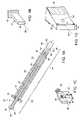
- FIG. 1( b )is a perspective view of a cannula of the invention.
- FIG. 1( c )is a perspective view of a clamp portion of the device of the invention.
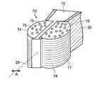
- FIG. 1( d )is a perspective view of one embodiment of supporting means of the invention.
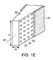
- FIG. 1( e )is a perspective view of another embodiment of supporting means of the invention.
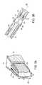
- FIG. 2( a )is a perspective view of one embodiment of a cage of the present invention.
- FIG. 2( b )is a lateral view of two embodiments of the cage of the present invention shown in FIG. 2( a ).
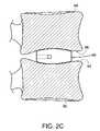
- FIG. 2( c )is a lateral view of one embodiment of the cage of the present invention shown in FIG. 2( a ).
- FIG. 3( a )is a perspective view of another embodiment of a cage of the present invention.
- FIG. 3( b )is a plan view of the embodiment of the cage of the present invention shown in FIG. 3( a ).
- FIG. 3( c )is a perspective view of another embodiment of a cage of the present invention.
- FIG. 4( a )is a perspective view of an embodiment of the present invention wherein a supporting means is a balloon.
- FIG. 4( b )is a plan view of the embodiment of the present invention shown in FIG. 4( a ).
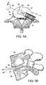
- FIG. 5( a )is a plan view depicting the embodiment of the device of the present invention, shown in FIGS. 2( a ) and ( b ), subsequent to the insertion of the device into an intervertebral space.
- FIG. 5( b )is a lateral view of the embodiment of the device depicted in FIG. 5( a ) (only the supporting means are shown).
- FIG. 5( c )is a perspective view depicting the embodiment of the device of the present invention, as shown in FIGS. 2( a ) and ( b ), subsequent to rotating the device (only the supporting means are shown).
- FIG. 5( d )is a lateral view of the embodiment of the device as depicted in FIG. 5( c ) (only the supporting means are shown).
- the present inventionrelates to a vertebral fusion device for simultaneously distracting two adjacent vertebral bodies and delivering a flowable material into a disk space.
- vertebral fusionrefers to a medical procedure that results in maintaining separation between vertebrae.
- vertebral fusionprovides for bony ingrowth that fixes two adjacent vertebrae in a desired, for example, distracted and/or angulated, position.
- a natural angle between two adjacent vertebral platesis replicated by fusing the two adjacent vertebrae.
- the “natural angle”refers either to natural lordosis or to natural kyphosis.
- a natural lordosisis replicated or restored.
- the term “natural lordosis”refers to a natural angle between two adjacent vertebral plates within the lumbar or cervical spine segments wherein the distance between the anterior portions of the two adjacent vertebral plates is not smaller than the distance between the posterior portions of the two adjacent vertebral plates.
- a natural kyphosisis replicated or restored.
- natural kyphosisrefers to a natural angle between two adjacent vertebral plates within the thoracic spine segment wherein the distance between the anterior portions of the two adjacent vertebral plates is not greater than the distance between the posterior portions of the two adjacent vertebral plates.
- a fusion meansmaintains the separation between the vertebrae.
- a device of the present inventioncan be used to distract the adjacent vertebrae, inject a flowable material, for example a fusion-promoting composition, in the intervertebral space and maintain the distracted vertebrae in the distracted position. Additionally, the present invention can be used to at least partially restore natural angle or disk space.
- a flowable materialfor example a fusion-promoting composition
- distal portion of the deviceis that portion that penetrates the annulus fibrosis, while the “proximal portion” of the device is that portion that remains outside the annulus fibrosis.
- the present inventionis an assembly that includes cannula 12 and device 20 .
- Cannula 12further includes proximal outlet 14 , distal outlet 16 and hilt 18 .
- Device 20having proximal portion 22 and distal portion 24 along major axis 26 , includes stopper 28 at proximal portion 22 , attached to central section 30 that spans proximal and distal portions 22 and 24 of device 20 , clamp 32 at distal portion 24 , attached to central section 30 and, preferably, connector 36 , attached to clamp 32 .
- the portion of device 20 that includes stopper 28 , central section 30 , clamp 32 and, preferably, connector 36is referred to herein as the “body” of the device.
- the terms “major axis,” labeled 26 in FIG. 1( a ), and “major axis of the body,”are used interchangeably herein.
- Device 20preferably has conduit 34 , substantially parallel to major axis 26 and defined by the body of the device.
- Conduit 34has inlet 38 , located at proximal portion 22 of device 20 , preferably in stopper 28 , and outlet 40 , located at a distal portion of clamp 32 or, preferably, at connector 36 .
- Cannula 12shown schematically in FIG. 1( b ), preferably has a rectangular cross-section taken perpendicular to major axis 26 .
- Clamp 32 and a distal portion of central section 30 of device 20are shown in FIG. 1( c ).
- central section 30 and connector 36have circular cross-sections taken perpendicular to major axis 26 .
- Device 20further includes supporting means 50 at the distal portion 22 for supporting vertebrae in a distracted position while the vertebrae fuse.
- at least one of the clamp 32 and the supporting means 50has a height H distinct from a width W taken along a cross-section of clamp 32 or supporting means 50 perpendicular to major axis 26 .
- clamp 32 or supporting means 50can distract vertebrae, between which clamp 32 or supporting means 50 has been placed, by rotation of device 20 , and thereby clamp 32 or supporting means 50 , about major axis 26 .
- a flowable materialcan be injected through conduit 34 into the disk space.
- supporting means 50includes supporting means conduit 52 having an inlet 53 and at least one outlet 54 . Preferably, there are two or more outlets 54 . Even more preferably, and now referring to FIG. 1( e ), supporting means 50 have multiple outlets 54 .
- Inlet 53 of supporting means conduit 52is preferably in fluid communication with outlet 40 of conduit 34 .
- supporting means 50is an integral part of clamp 32 . In a preferred embodiment, supporting means 50 are detachably connected to clamp 32 and connector 36 .
- inlet 38includes a connection means (not shown) to an injection means (not shown).
- Suitable connection meansinclude a rubber or plastic hose or tube.
- Suitable injection meansinclude syringe and a pump.
- the injection meansis a syringe.
- supporting means 50is selected from the group consisting of a cage, a balloon and a ramp.
- the supporting meansis a cage 60 , depicted in a perspective view in FIG. 2( a ) and, as a non-limiting example, in FIGS. 1( a ), ( d ) and ( e ).
- cage 60is detachably connected to clamp 32 and, more preferably, to connector 36 .
- cage 60defines supporting means conduit 52 that is in fluid communication with conduit 34 defined by the body of device 20 . Referring to FIG.
- cage 60has a height H distinct from a width W taken along a cross-section of cage 60 perpendicular to major axis 26 .
- cage 60can distract vertebrae, between which it has been placed, by rotation of device 20 , and thereby cage 60 , about major axis 26 .
- cage 60substantially maintains natural angle between the distracted vertebrae.
- cage 60substantially maintains a natural angle between the distracted vertebrae upon detachment of clamp 32 or connector 36 from cage 60 .
- cage 60has an upper bearing surface 62 , a lower bearing surface 64 and lateral surfaces 66 .
- the upper and lower surfacesdefine a non-zero angle ⁇ , thereby providing an anterior-posterior angle to the distracted disc space.
- the angle ⁇is between about 5 and about 15 degrees.
- the angle ⁇ defined by the upper and the lower bearing surfacesis between about ⁇ 5 and about ⁇ 15 degrees.
- the portion of the supporting means having the greater heightis preferably facing the anterior side, thus providing lordosis to the spine segment.
- the portion of the supporting means having the greater heightis preferably facing the posterior side, thus providing kyphosis to the spine segment.
- the supporting memberis inserted into the disc space through a transforaminal posterior approach, which causes the device to lie at an angle to the sagittal plane.
- the angle, defined by the upper and lower bearing surfaces,is defined along the saggital plane, therefore the supporting member is angled both along the major axis and transversely to the major axis.
- cage 60has at least one of the bearing surfaces 62 and 64 having a convex shape substantially adapted to match the contour of the vertebral endplates 92 and 94 .
- supporting means 50is cage 70 , depicted in perspective view in FIG. 3( a ) and, in plan view, in FIG. 3( b ).
- Cage 70includes frame 72 and at least two expandable balloons 74 , connected to frame 72 .
- Cage 70defines therewithin a supporting means conduit 52 .
- Supporting means conduit 52is in fluid communication with balloons 74 and with conduit 34 defined by the body of device 20 .
- cage 70is detachably connected to clamp 32 and, more preferably, to connector 36 .
- cage 70has a height H distinct from a width W taken along a cross-section of cage 70 perpendicular to major axis 26 .
- cage 70can distract vertebrae, between which it has been placed, by rotation of device 20 , and thereby cage 70 , about major axis 26 .
- cage 70substantially maintains a natural angle between the distracted vertebrae.
- cage 70substantially maintains a natural angle between the distracted vertebrae upon detachment of clamp 32 or connector 36 from cage 70 .
- balloons 74expand substantially in the lateral direction indicated by arrow A.
- balloons 74have multiple outlets 75 located on upper and lower balloon surfaces 76 and 77 .
- a flowable materialcan be injected through conduit 34 and 52 into balloons 74 .
- the flowable materialis allowed to come in contact with the adjacent vertebrae through outlets 75 .
- the balloonis substantially semi-permeable, whereby leakage outside of the disc space is prevented, while allowing direct contact of the flowable material with the vertebral body endplates.
- supporting means 50is an expandable balloon 80 .
- Balloon 80is in fluid communication with conduit 34 defined by the body of device 20 .
- balloon 80is detachably connected to clamp 32 and, more preferably, to connector 36 .
- clamp 32 and balloon 80subsequent to expansion, have a height H distinct from a width W taken along a cross-section of clamp 32 or balloon 80 perpendicular to major axis 26 .
- clamp 32can distract vertebrae, between which clamp 32 has been placed, by rotation of device 20 , and thereby clamp 32 about major axis 26 .
- a flowable, preferably hardenable, materialcan be injected through conduit 34 into balloon 80 .
- expanded balloon 80substantially maintains natural angle between the distracted vertebrae. In a preferred embodiment, expanded balloon 80 substantially maintains natural angle between the distracted vertebrae upon detachment of clamp 32 or connector 36 from expanded balloon 80 .
- the devicecan be made of materials typically selected for use in surgical instruments and implants, such as stainless steel, titanium, titanium alloys (Ti-6Al-4V), cobalt-chrome alloys.
- the entire deviceis sterile.
- the supporting means 50includes at least one material selected from the group consisting cortical bone graft, bioabsorbable polymer such as poly(lactic acid), poly(glycolic acid), polydioxanone, polyhydroxybutyrate, polyhydroxyvalerate, poly(propylene fumarate), polyoxaesters, amino acid-derived polycarbonates, biodegradable polyurethanes and their copolymers, and non-bioabsorbable polymer such as ether-ketone polymers (polyetheretherketone), poly(ethylene terephthalate), poysulfone, polypropylene, and nylon.
- bioabsorbable polymersuch as poly(lactic acid), poly(glycolic acid), polydioxanone, polyhydroxybutyrate, polyhydroxyvalerate, poly(propylene fumarate), polyoxaesters, amino acid-derived polycarbonates, biodegradable polyurethanes and their copolymers, and non-bioabsorbable polymer such as ether
- the devices of the inventioninclude at least one balloon.
- at least one balloonprovides relative containment of the flowable material during injection, thereby preventing leakage outside of the disc space.
- at least one balloonis semi-permeable, thereby preventing leakage outside of the disc space, while allowing direct contact of the flowable material with the vertebral body endplates.
- the ballooncomprises a biodegradable polymer having a high rate of degradation that would allow the flowable material to contact the vertebral endplates following degradation. Examples include low-molecular weight polymers of lactic and glycolic acid, modified lactic and glycolic acid polymers such as hydroxylated poly(glycolic-co-lactic acid, collagen, and oxidized regenerated cellulose.
- the devices of the inventioninclude at least one balloon that further includes a material selected from the group consisting of polyurethanes, polyolefin copolymers, polyethylene, polycarbonate, polyethylene terephthalate, ether-ketone polymers, woven fibers, non-woven fibers, fabrics and metal mesh.
- a materialselected from the group consisting of polyurethanes, polyolefin copolymers, polyethylene, polycarbonate, polyethylene terephthalate, ether-ketone polymers, woven fibers, non-woven fibers, fabrics and metal mesh.
- the devices of the inventioncan either be made of or include any member of the group consisting of polyetheretherketone (PEEK), polyether block copolymer (PEBAX), acrylonitrile butadiene styrene (ABS), acrylonitrile styrene (ANS), delrin acetal, polyvinyl chloride (PVC), polyethylene napthalate (PEN), polybutylene terephthalate (PBT), polycarbonate, polyetherimide (PEI), polyether sulfone (PES), polyethylene terephthalate (PET), polyethylene terephthalate glycol (PETG), polyamide, aromatic polyamide, polyether, polyester, polymethylmethacrylate, polyurethane copolymer, ethylene vinyl acetate (EVA), ethylene vinyl alcohol, polyethylene, latex rubber, poly tetrafluoroethylene (PTFE), polypropylene, polyolefin, polysiloxane, liquid crystal polymer, ionomer, poly
- Flowable materialscan include a material that hardens into a structure capable of supporting the loads typically experienced by a intervertebral disc.
- the flowable materialhardens into a porous scaffold into which bone can grow from the surroundings.
- the flowable materialhardens into a cement that can induce bone growth.
- Suitable materialsinclude at least one compound selected from the group consisting of poly(lactic acid) (PLA), poly(glycolic acid), p-dioxanone fibers, polyarylethyl, polymethylmethacrylate, polyurethane, amino-acid-derived polycarbonate, polycaprolactone, aliphatic polyesters, calcium phosphate, unsaturated linear polyesters, vinyl pyrrolidone and polypropylene fumarate diacrylate or mixtures thereof.
- PVApoly(lactic acid)
- poly(glycolic acid)poly(glycolic acid)
- p-dioxanone fiberspolyarylethyl, polymethylmethacrylate, polyurethane, amino-acid-derived polycarbonate, polycaprolactone, aliphatic polyesters, calcium phosphate, unsaturated linear polyesters, vinyl pyrrolidone and polypropylene fumarate diacrylate or mixtures thereof.
- suitable flowable materialscan include at least one member selected from the group consisting of mesenchymal stem cells, growth factors, cancellous bone chips, hydroxyapatite, tri-calcium phosphate, polylactic acid polyglycolic acid, polygalactic acid, polycaprolactone, polyethylene oxide, polypropylene oxide, polysulfone, polyethylene, polypropylene, hyaluronic acid, bioglass, gelatin, collagen and chopped polymeric fibers, or mixtures thereof.
- suitable flowable materialscan include compounds that stimulate and/or support bone growth, such as morsellized autograft, demineralized bone matrix, bone marrow aspirate, bone marrow concentrate, platelet-rich plasma, hyaluronic acid, collagen, calcium phosphate cements, and bioabsorbable polymers.
- compounds that stimulate and/or support bone growthsuch as morsellized autograft, demineralized bone matrix, bone marrow aspirate, bone marrow concentrate, platelet-rich plasma, hyaluronic acid, collagen, calcium phosphate cements, and bioabsorbable polymers.
- these compoundsinclude growth factors, differentiation factor and cytokines selected from the group consisting of FGF-1, FGF-2, FGF-4, PDGFs, EGFs, IGFs, PDGF-bb, OP-1, TGF- ⁇ , osteoid-inducing factor (OIF), angiogenin(s), endothelins, hepatocyte growth factor and keratinocyte growth factor, osteogenin (BMP-3); BMP-2; OP-1; BMP-2A, -2B, and -7; TGF- ⁇ , HBGF-1, HBGF-2; isoforms of platelet-derived growth factors (PDGF), fibroblast growth factors, epithelial growth factors, isoforms of TGF- ⁇ , insulin-like growth factors, bone morphogenic proteins, FGF-1 and 4, TGF- ⁇ 1, TGF- ⁇ 2, TGF- ⁇ 3, the bone morphogenetic proteins (BMP's), the growth differentiation factors (GDF's), Indian hedgehog, sonic hedgehog, desert hedge
- the bone growth supporting compoundsfurther include at least one of material selected from the group consisting of mono-calcium phosphate, di-calcium phosphate, octa-calcium phosphate, alpha-tri-calcium phosphate, beta-tri-calcium phosphate, or tetra-calcium phosphate, hydroxyapatite, fluorapatite, calcium sulfate, calcium fluoride, calcium oxide, silicon dioxide, sodium oxide, and phosphorus pentoxide, or mixtures thereof.
- materialselected from the group consisting of mono-calcium phosphate, di-calcium phosphate, octa-calcium phosphate, alpha-tri-calcium phosphate, beta-tri-calcium phosphate, or tetra-calcium phosphate, hydroxyapatite, fluorapatite, calcium sulfate, calcium fluoride, calcium oxide, silicon dioxide, sodium oxide, and phosphorus pentoxide, or mixtures thereof.
- a kit for providing a fusion-promoting materialcomprising the device of the present invention and a flowable material.
- the present inventionis a method of fusing vertebrae.
- the methodincludes a step of inserting between two vertebrae an intervertebral fusion device 20 , said device having a proximal portion 22 and distal portion 24 along major axis 26 , a stopper 28 at proximal portion 22 connected to a central section 30 , that spans proximal and distal portions 22 and 24 of device 20 , clamp 32 at distal portion 24 , connected to central section 30 and, preferably, connector 36 , connected to clamp 32 .
- the portion of device 20 that includes stopper 28 , central section 30 , clamp 32 and, preferably, connector 36is referred to herein as the “body” of the device.
- the terms “major axis,” labeled 26 in FIG. 1( a ), and “major axis of the body,”are used interchangeably herein.
- the intervertebral fusion devicefurther includes supporting means 50 at the distal portion 24 for supporting vertebrae in a distracted position while the vertebrae fuse, wherein at least one of clamp 32 and the supporting means 50 has a height H distinct from a width W taken along a cross-section of clamp 32 or supporting means 50 perpendicular to major axis 26 , whereby clamp 32 or supporting means 50 can distract vertebrae, between which clamp 32 or supporting means 50 has been placed, by rotation of device 20 or supporting means 50 about the major axis 26 and further wherein the supporting means define a conduit substantially parallel to major axis.
- the methodfurther includes the step of rotating device 20 or supporting means 50 , whereby the vertebrae are supported in a distracted position while the vertebrae fuse, thereby fusing the vertebrae.
- supporting means 50is inserted between the vertebrae.
- either supporting means 50 or clamp 32has a height H distinct from a width W taken along a cross-section perpendicular to major axis 26 .
- rotation of device 20 , and thereby of supporting means 50distracts the vertebrae.
- rotation of device 20 , and thereby of supporting means 50at least partially restores natural angle between the vertebrae.
- an intervertebral disk between said vertebraeis removed resulting in formation of an intervertebral space.
- the device of the present inventioncan be used immediately after a discectomy or a nucleotomy. In performing the discectomy or a nucleotomy, the surgeon typically makes a small ( ⁇ 5 mm) hole in the annulus fibrosis through which the nucleus pulposus is removed.
- the surgeonmakes a device entry hole in the annulus fibrosis.
- the device entry holeis typically made by either making a second hole in the annulus fibrosis larger than the hole through which the nucleotomy is performed or, preferably, by enlarging the hole through which the nucleotomy is performed.
- the method of the present inventioncan further include the step of removing at least a portion of an intervertebral disk between said vertebrae to thereby form an intervertebral space.
- the intervertebral spacecan at least partially be filled with at least one member of the group consisting of autologous bone graft, allograft, demineralized bone matrix, tricalcium phosphate granules, bioabsorbable polymer and non-bioabsorbable polymer.
- the method of the present inventioncan further include the step of directing at least one member selected from the group consisting of morsellized autograft, demineralized bone matrix, bone marrow aspirate, bone marrow concentrate, platelet-rich plasma, hyaluronic acid, collagen, calcium phosphate cements, and bioabsorbable polymers, into supporting means conduit 52 defined the supporting means 50 .
- the flowable materialis delivered into the disk space through supporting means conduit 52 and outlets 54 .
- supporting means 50is an integral part of clamp 32 .
- the surgeonpreferably allows the material to at least partially cure within the disc space to a point where the at least partially cured material can withstand the, compressive forces of the spine without leaking into the spinal canal, then the clamp and supporting means are removed.
- supporting means 50is detachably connected to clamp 32 or connector 36 . In this embodiment, the surgeon can remove device 20 from the intervertebral space and leave supporting means in said space.
- either balloons 74 of cage 70 or balloon 80are filled by directing a flowable material, for example, morsellized autograft, demineralized bone matrix, bone marrow aspirate, bone marrow concentrate, platelet-rich plasma, hyaluronic acid, collagen, calcium phosphate cements, and bioabsorbable polymers through conduit 34 defined by device 20 .
- a flowable materialfor example, morsellized autograft, demineralized bone matrix, bone marrow aspirate, bone marrow concentrate, platelet-rich plasma, hyaluronic acid, collagen, calcium phosphate cements, and bioabsorbable polymers
- the flowable materialis delivered into balloon 80 .
- the surgeonpreferably allows the material to at least partially cure within the disc space to a point where the at least partially cured material can withstand the compressive forces of the spine. At this time, the surgeon can remove device 20 from the patient, leaving supporting means 50 that includes balloon 80 in the intervertebral space.
- the flowable materialis delivered into balloons 74 of cage 70 .
- cage 70is detachably connected to clamp 32 or connector 36 .
- the surgeoncan remove device 20 from the intervertebral space and leave cage 70 in said space prior to allowing the flowable material to cure.
- the deployment of the cage 60will be illustrated below.
- FIGS. 5( a ) and 5 ( b )according to the method of the present invention, the surgeon advances assembly 10 through an incision in the annulus fibrosis, and follows by insertion of cage 60 between lower vertebra 90 and the upper vertebra 94 ( FIG. 5( b )) in a direction shown by arrow A as depicted in FIG. 5( a ).
- the initial orientation of cage 60is such that the lateral surfaces 66 are essentially parallel to lower endplate 92 and upper endplate 96 .
- FIG. 5( b )shows the position assumed by cage 60 in the intervertebral space subsequent to the insertion (for clarity, only cage 60 is shown).
- the surgeonrotates device 20 (not shown), including cage 60 , by about 90° (as shown by arrow B in FIG. 5( a )) to the final orientation whereby the bearing surfaces 64 and 62 are in contact with lower endplate 92 and upper endplate 96 ( FIG. 5( d )) respectively.
- cage 60Since, in this example, cage 60 has its height H greater than its width W (see FIG. 5( c )), the rotation achieves the desired distraction of the vertebral bodies 92 and 94 .
- the intervertebral space(the space between vertebrae 90 and 94 ) is filled by directing a flowable, fusion-promoting material through conduit 34 , supporting means conduit 52 and supporting means conduit outlet 53 .
- the surgeonthen allows the material to begin to cure within the disc space to a point where the at least partially cured material can withstand the compressive forces of the spine without leaking into the spinal canal.
- the surgeoncan remove device 20 and cage 60 from the patient.
- the surgeonsubsequent to filling the intervertebral space with a flowable, fusion-promoting material, detaches cage 60 from clamp 36 and removes device 20 without cage 60 from the patient. In this embodiment, it is not necessary to allow the material to begin to cure.
Landscapes
- Health & Medical Sciences (AREA)
- Engineering & Computer Science (AREA)
- Biomedical Technology (AREA)
- Orthopedic Medicine & Surgery (AREA)
- Neurology (AREA)
- Life Sciences & Earth Sciences (AREA)
- General Health & Medical Sciences (AREA)
- Veterinary Medicine (AREA)
- Transplantation (AREA)
- Heart & Thoracic Surgery (AREA)
- Public Health (AREA)
- Animal Behavior & Ethology (AREA)
- Oral & Maxillofacial Surgery (AREA)
- Vascular Medicine (AREA)
- Cardiology (AREA)
- Surgery (AREA)
- Physical Education & Sports Medicine (AREA)
- Chemical & Material Sciences (AREA)
- Dispersion Chemistry (AREA)
- Pathology (AREA)
- Nuclear Medicine, Radiotherapy & Molecular Imaging (AREA)
- Medical Informatics (AREA)
- Molecular Biology (AREA)
- Prostheses (AREA)
Abstract
Description
Claims (15)
Priority Applications (7)
| Application Number | Priority Date | Filing Date | Title |
|---|---|---|---|
| US10/675,580US7655010B2 (en) | 2003-09-30 | 2003-09-30 | Vertebral fusion device and method for using same |
| CA2540525ACA2540525C (en) | 2003-09-30 | 2004-09-29 | Vertebral fusion device and method for using same |
| JP2006534028AJP2007507299A (en) | 2003-09-30 | 2004-09-29 | Vertebral fixation device and method of use thereof |
| PCT/US2004/031846WO2005032435A1 (en) | 2003-09-30 | 2004-09-29 | Vertebral fusion device and method for using same |
| AU2004277963AAU2004277963B2 (en) | 2003-09-30 | 2004-09-29 | Vertebral fusion device and method for using same |
| EP04785211AEP1670398B1 (en) | 2003-09-30 | 2004-09-29 | Vertebral fusion device and method for using same |
| AT04785211TATE551029T1 (en) | 2003-09-30 | 2004-09-29 | INTEGRATED FUSION DEVICE AND METHOD OF USE THEREOF |
Applications Claiming Priority (1)
| Application Number | Priority Date | Filing Date | Title |
|---|---|---|---|
| US10/675,580US7655010B2 (en) | 2003-09-30 | 2003-09-30 | Vertebral fusion device and method for using same |
Publications (2)
| Publication Number | Publication Date |
|---|---|
| US20050070900A1 US20050070900A1 (en) | 2005-03-31 |
| US7655010B2true US7655010B2 (en) | 2010-02-02 |
Family
ID=34377194
Family Applications (1)
| Application Number | Title | Priority Date | Filing Date |
|---|---|---|---|
| US10/675,580Expired - LifetimeUS7655010B2 (en) | 2003-09-30 | 2003-09-30 | Vertebral fusion device and method for using same |
Country Status (7)
| Country | Link |
|---|---|
| US (1) | US7655010B2 (en) |
| EP (1) | EP1670398B1 (en) |
| JP (1) | JP2007507299A (en) |
| AT (1) | ATE551029T1 (en) |
| AU (1) | AU2004277963B2 (en) |
| CA (1) | CA2540525C (en) |
| WO (1) | WO2005032435A1 (en) |
Cited By (54)
| Publication number | Priority date | Publication date | Assignee | Title |
|---|---|---|---|---|
| US20090248164A1 (en)* | 2006-01-26 | 2009-10-01 | Spinal Generations, Llc | Interbody cage system |
| US20100262240A1 (en)* | 2007-11-16 | 2010-10-14 | Kris Chavatte | Porous containment device and associated method for stabilization of vertebral compression fractures |
| US8679184B2 (en) | 2011-04-07 | 2014-03-25 | 5K Ip-1 Llc | Interbody cage for spinal fusion and method of implanting interbody cages into spines |
| US8956414B2 (en) | 2010-04-21 | 2015-02-17 | Spinecraft, LLC | Intervertebral body implant, instrument and method |
| US9044284B2 (en) | 2010-09-29 | 2015-06-02 | Spinal Generations, Llc | Intervertebral insert system |
| US9216096B2 (en) | 2010-03-16 | 2015-12-22 | Pinnacle Spine Group, Llc | Intervertebral implants and related tools |
| US9277944B2 (en) | 2006-04-20 | 2016-03-08 | DePuy Synthes Products, Inc. | Instrumentation kit for delivering viscous bone filler material |
| US9289240B2 (en) | 2005-12-23 | 2016-03-22 | DePuy Synthes Products, Inc. | Flexible elongated chain implant and method of supporting body tissue with same |
| US9320614B2 (en) | 2006-07-31 | 2016-04-26 | DePuy Synthes Products, Inc. | Spinal fusion implant |
| US9333091B2 (en) | 2003-02-14 | 2016-05-10 | DePuy Synthes Products, Inc. | In-situ formed intervertebral fusion device and method |
| US9380932B1 (en) | 2011-11-02 | 2016-07-05 | Pinnacle Spine Group, Llc | Retractor devices for minimally invasive access to the spine |
| US9421056B2 (en) | 2007-09-28 | 2016-08-23 | DePuy Synthes Products, Inc. | Balloon with shape control for spinal procedures |
| US9498263B2 (en) | 2005-05-27 | 2016-11-22 | DePuy Synthes Products, Inc. | Prosthetic ligament having a helical bone fastener |
| US9539041B2 (en) | 2013-09-12 | 2017-01-10 | DePuy Synthes Products, Inc. | Minimally invasive biomaterial injection system |
| US9592063B2 (en) | 2010-06-24 | 2017-03-14 | DePuy Synthes Products, Inc. | Universal trial for lateral cages |
| US9662148B2 (en) | 2004-03-06 | 2017-05-30 | DePuy Synthes Products, Inc. | Dynamized interspinal implant |
| US9801725B2 (en) | 2009-12-09 | 2017-10-31 | DePuy Synthes Products, Inc. | Aspirating implants and method of bony regeneration |
| US9931224B2 (en) | 2009-11-05 | 2018-04-03 | DePuy Synthes Products, Inc. | Self-pivoting spinal implant and associated instrumentation |
| US10022245B2 (en) | 2012-12-17 | 2018-07-17 | DePuy Synthes Products, Inc. | Polyaxial articulating instrument |
| US10070970B2 (en) | 2013-03-14 | 2018-09-11 | Pinnacle Spine Group, Llc | Interbody implants and graft delivery systems |
| US10238500B2 (en) | 2002-06-27 | 2019-03-26 | DePuy Synthes Products, Inc. | Intervertebral disc |
| US10398425B2 (en) | 2004-02-09 | 2019-09-03 | Medos International Sarl | Systems and methods for spinal surgery |
| US10531957B2 (en) | 2015-05-21 | 2020-01-14 | Musculoskeletal Transplant Foundation | Modified demineralized cortical bone fibers |
| US10537435B2 (en) | 2007-05-17 | 2020-01-21 | DePuy Synthes Products, Inc. | Self-distracting cage |
| US10646353B2 (en) | 2004-04-26 | 2020-05-12 | DePuy Synthes Products, Inc. | Intervertebral prosthesis or disk prosthesis |
| US10888433B2 (en) | 2016-12-14 | 2021-01-12 | DePuy Synthes Products, Inc. | Intervertebral implant inserter and related methods |
| US10940016B2 (en) | 2017-07-05 | 2021-03-09 | Medos International Sarl | Expandable intervertebral fusion cage |
| US10966843B2 (en) | 2017-07-18 | 2021-04-06 | DePuy Synthes Products, Inc. | Implant inserters and related methods |
| US10966840B2 (en) | 2010-06-24 | 2021-04-06 | DePuy Synthes Products, Inc. | Enhanced cage insertion assembly |
| US10973652B2 (en) | 2007-06-26 | 2021-04-13 | DePuy Synthes Products, Inc. | Highly lordosed fusion cage |
| US11013602B2 (en) | 2016-07-08 | 2021-05-25 | Mako Surgical Corp. | Scaffold for alloprosthetic composite implant |
| US11045331B2 (en) | 2017-08-14 | 2021-06-29 | DePuy Synthes Products, Inc. | Intervertebral implant inserters and related methods |
| US11273050B2 (en) | 2006-12-07 | 2022-03-15 | DePuy Synthes Products, Inc. | Intervertebral implant |
| US11344424B2 (en) | 2017-06-14 | 2022-05-31 | Medos International Sarl | Expandable intervertebral implant and related methods |
| US11369490B2 (en) | 2011-03-22 | 2022-06-28 | DePuy Synthes Products, Inc. | Universal trial for lateral cages |
| US11426290B2 (en) | 2015-03-06 | 2022-08-30 | DePuy Synthes Products, Inc. | Expandable intervertebral implant, system, kit and method |
| US11426286B2 (en) | 2020-03-06 | 2022-08-30 | Eit Emerging Implant Technologies Gmbh | Expandable intervertebral implant |
| US11446156B2 (en) | 2018-10-25 | 2022-09-20 | Medos International Sarl | Expandable intervertebral implant, inserter instrument, and related methods |
| US11446155B2 (en) | 2017-05-08 | 2022-09-20 | Medos International Sarl | Expandable cage |
| US11452607B2 (en) | 2010-10-11 | 2022-09-27 | DePuy Synthes Products, Inc. | Expandable interspinous process spacer implant |
| US11497619B2 (en) | 2013-03-07 | 2022-11-15 | DePuy Synthes Products, Inc. | Intervertebral implant |
| US11510788B2 (en) | 2016-06-28 | 2022-11-29 | Eit Emerging Implant Technologies Gmbh | Expandable, angularly adjustable intervertebral cages |
| US11596522B2 (en) | 2016-06-28 | 2023-03-07 | Eit Emerging Implant Technologies Gmbh | Expandable and angularly adjustable intervertebral cages with articulating joint |
| US11602438B2 (en) | 2008-04-05 | 2023-03-14 | DePuy Synthes Products, Inc. | Expandable intervertebral implant |
| US11607321B2 (en) | 2009-12-10 | 2023-03-21 | DePuy Synthes Products, Inc. | Bellows-like expandable interbody fusion cage |
| US11612491B2 (en) | 2009-03-30 | 2023-03-28 | DePuy Synthes Products, Inc. | Zero profile spinal fusion cage |
| US11612493B2 (en) | 2003-06-30 | 2023-03-28 | DePuy Synthes Products, Inc. | Intervertebral implant with conformable endplate |
| US11654033B2 (en) | 2010-06-29 | 2023-05-23 | DePuy Synthes Products, Inc. | Distractible intervertebral implant |
| US11737881B2 (en) | 2008-01-17 | 2023-08-29 | DePuy Synthes Products, Inc. | Expandable intervertebral implant and associated method of manufacturing the same |
| US11752009B2 (en) | 2021-04-06 | 2023-09-12 | Medos International Sarl | Expandable intervertebral fusion cage |
| US11850160B2 (en) | 2021-03-26 | 2023-12-26 | Medos International Sarl | Expandable lordotic intervertebral fusion cage |
| USRE49973E1 (en) | 2013-02-28 | 2024-05-21 | DePuy Synthes Products, Inc. | Expandable intervertebral implant, system, kit and method |
| US12090064B2 (en) | 2022-03-01 | 2024-09-17 | Medos International Sarl | Stabilization members for expandable intervertebral implants, and related systems and methods |
| US12440346B2 (en) | 2023-03-31 | 2025-10-14 | DePuy Synthes Products, Inc. | Expandable intervertebral implant |
Families Citing this family (60)
| Publication number | Priority date | Publication date | Assignee | Title |
|---|---|---|---|---|
| US7011684B2 (en)* | 2002-01-17 | 2006-03-14 | Concept Matrix, Llc | Intervertebral disk prosthesis |
| US8012210B2 (en)* | 2004-01-16 | 2011-09-06 | Warsaw Orthopedic, Inc. | Implant frames for use with settable materials and related methods of use |
| US7651499B2 (en)* | 2004-10-26 | 2010-01-26 | Concept Matrix, Llc | Working channel for minimally invasive spine surgery |
| CH697330B1 (en) | 2004-12-28 | 2008-08-29 | Synthes Gmbh | Intervertebral prosthesis. |
| JP4709892B2 (en)* | 2005-03-24 | 2011-06-29 | シンセス ゲゼルシャフト ミット ベシュレンクテル ハフツング | Bone implant adhesion enhancer |
| US8162992B2 (en)* | 2005-04-30 | 2012-04-24 | Warsaw Orthopedic, Inc. | Spinal fusion with osteogenic material and migration barrier |
| US7955339B2 (en)* | 2005-05-24 | 2011-06-07 | Kyphon Sarl | Low-compliance expandable medical device |
| US7883542B2 (en)* | 2005-06-03 | 2011-02-08 | Zipnick Richard I | Minimally invasive apparatus to manipulate and revitalize spinal column disc |
| US20070010844A1 (en)* | 2005-07-08 | 2007-01-11 | Gorman Gong | Radiopaque expandable body and methods |
| EP1909707A2 (en)* | 2005-07-11 | 2008-04-16 | Kyphon Inc. | Systems and methods for providing prostheses |
| US7988695B2 (en)* | 2005-12-21 | 2011-08-02 | Theken Spine, Llc | Articulated delivery instrument |
| US20070233258A1 (en)* | 2006-02-28 | 2007-10-04 | Zimmer Spine, Inc. | Vertebroplasty- device and method |
| US8323290B2 (en)* | 2006-03-03 | 2012-12-04 | Biomet Manufacturing Corp. | Tensor for use in surgical navigation |
| US7976549B2 (en)* | 2006-03-23 | 2011-07-12 | Theken Spine, Llc | Instruments for delivering spinal implants |
| US7794501B2 (en)* | 2006-04-27 | 2010-09-14 | Wasaw Orthopedic, Inc. | Expandable intervertebral spacers and methods of use |
| US20080071379A1 (en)* | 2006-05-10 | 2008-03-20 | Mark Rydell | Intervertebral disc replacement |
| US20080058954A1 (en)* | 2006-08-22 | 2008-03-06 | Hai Trieu | Methods of treating spinal injuries using injectable flowable compositions comprising organic materials |
| US8506636B2 (en)* | 2006-09-08 | 2013-08-13 | Theken Spine, Llc | Offset radius lordosis |
| US20080077150A1 (en)* | 2006-09-22 | 2008-03-27 | Linh Nguyen | Steerable rasp/trial member inserter and method of use |
| US20080082170A1 (en)* | 2006-09-29 | 2008-04-03 | Peterman Marc M | Apparatus and methods for surgical repair |
| US7824427B2 (en)* | 2007-01-16 | 2010-11-02 | Perez-Cruet Miquelangelo J | Minimally invasive interbody device |
| US8034081B2 (en) | 2007-02-06 | 2011-10-11 | CollabComl, LLC | Interspinous dynamic stabilization implant and method of implanting |
| US8172905B2 (en)* | 2007-04-27 | 2012-05-08 | Atlas Spine, Inc. | Spinal implant |
| US8083799B2 (en)* | 2007-04-27 | 2011-12-27 | Atlas Spine, Inc. | Spinal implant |
| US20090112217A1 (en)* | 2007-10-31 | 2009-04-30 | Douglas Hester | Implant insertion device |
| US8888850B2 (en)* | 2007-11-19 | 2014-11-18 | Linares Medical Devices, Llc | Combination spacer insert and support for providing inter-cervical vertebral support |
| US8088163B1 (en) | 2008-02-06 | 2012-01-03 | Kleiner Jeffrey B | Tools and methods for spinal fusion |
| US8323345B2 (en)* | 2008-02-14 | 2012-12-04 | U.S. Spine, Inc. | Anterior lumbar interbody fusion cage device and associated method |
| US20210378834A1 (en) | 2008-05-22 | 2021-12-09 | Spinal Surgical Strategies, Inc., A Nevada Corporation D/B/A Kleiner Device Labs | Spinal fusion cage system with inserter |
| US20100004745A1 (en)* | 2008-07-01 | 2010-01-07 | Doctors Research Group, Inc. | Fusing Bone |
| US20100042219A1 (en)* | 2008-08-14 | 2010-02-18 | Mark Darryl Antonacci | Expandable cage for intervertebral body fusion |
| US8366748B2 (en) | 2008-12-05 | 2013-02-05 | Kleiner Jeffrey | Apparatus and method of spinal implant and fusion |
| US9247943B1 (en) | 2009-02-06 | 2016-02-02 | Kleiner Intellectual Property, Llc | Devices and methods for preparing an intervertebral workspace |
| US10973656B2 (en) | 2009-09-18 | 2021-04-13 | Spinal Surgical Strategies, Inc. | Bone graft delivery system and method for using same |
| US20170238984A1 (en) | 2009-09-18 | 2017-08-24 | Spinal Surgical Strategies, Llc | Bone graft delivery device with positioning handle |
| US9173694B2 (en) | 2009-09-18 | 2015-11-03 | Spinal Surgical Strategies, Llc | Fusion cage with combined biological delivery system |
| US9060877B2 (en) | 2009-09-18 | 2015-06-23 | Spinal Surgical Strategies, Llc | Fusion cage with combined biological delivery system |
| USD750249S1 (en) | 2014-10-20 | 2016-02-23 | Spinal Surgical Strategies, Llc | Expandable fusion cage |
| US10245159B1 (en) | 2009-09-18 | 2019-04-02 | Spinal Surgical Strategies, Llc | Bone graft delivery system and method for using same |
| US9186193B2 (en) | 2009-09-18 | 2015-11-17 | Spinal Surgical Strategies, Llc | Fusion cage with combined biological delivery system |
| US8906028B2 (en) | 2009-09-18 | 2014-12-09 | Spinal Surgical Strategies, Llc | Bone graft delivery device and method of using the same |
| US9629729B2 (en) | 2009-09-18 | 2017-04-25 | Spinal Surgical Strategies, Llc | Biological delivery system with adaptable fusion cage interface |
| AU2011305680B2 (en)* | 2010-09-20 | 2014-09-11 | Jeffrey Kleiner | Fusion cage with combined biological delivery system |
| WO2012138314A1 (en) | 2011-04-06 | 2012-10-11 | David John Kusko | Hydroelectric control valve for remote locations |
| EP3461509A1 (en) | 2011-07-13 | 2019-04-03 | Vivex Biomedical, Inc. | Spinal implants with stem cells |
| US9451998B2 (en) | 2012-08-17 | 2016-09-27 | Warsaw Orthopedic, Inc. | Spinal implant system and method |
| US9585761B2 (en) | 2013-03-14 | 2017-03-07 | DePuy Synthes Products, Inc. | Angulated rings and bonded foils for use with balloons for fusion and dynamic stabilization |
| US9572676B2 (en)* | 2013-03-14 | 2017-02-21 | DePuy Synthes Products, Inc. | Adjustable multi-volume balloon for spinal interventions |
| US9358120B2 (en) | 2013-03-14 | 2016-06-07 | DePuy Synthes Products, Inc. | Expandable coil spinal implant |
| US9730802B1 (en) | 2014-01-14 | 2017-08-15 | Nuvasive, Inc. | Spinal fusion implant and related methods |
| WO2015123693A1 (en)* | 2014-02-14 | 2015-08-20 | Spectrum Spine Ip Holdings, Llc | Cervical minimal access fusion system |
| AU2016200195B2 (en) | 2015-01-14 | 2020-07-02 | Vb Spine Us Opco Llc | Spinal implant with fluid delivery capabilities |
| AU2016200179B2 (en) | 2015-01-14 | 2020-09-17 | Stryker European Operations Holdings Llc | Spinal implant with porous and solid surfaces |
| CA2930123A1 (en) | 2015-05-18 | 2016-11-18 | Stryker European Holdings I, Llc | Partially resorbable implants and methods |
| USD797290S1 (en) | 2015-10-19 | 2017-09-12 | Spinal Surgical Strategies, Llc | Bone graft delivery tool |
| EP3459502B1 (en) | 2017-09-20 | 2024-05-22 | Stryker European Operations Holdings LLC | Spinal implants |
| CN108309517B (en)* | 2018-01-25 | 2019-08-30 | 中国人民解放军新疆军区总医院 | A kind of absorbable cervical fusion cage and preparation method thereof |
| CN111839829B (en)* | 2020-06-09 | 2023-06-09 | 遵义医科大学附属医院 | Zero notch interbody fusion cage |
| US20220133490A1 (en)* | 2020-11-05 | 2022-05-05 | Michael Murray | Methods and Implants for Facet Joint Stabilization or Fusion |
| CN116269953A (en)* | 2021-12-20 | 2023-06-23 | 影为医疗科技(上海)有限公司 | Holder and implantation instrument assembly |
Citations (42)
| Publication number | Priority date | Publication date | Assignee | Title |
|---|---|---|---|---|
| US3875595A (en)* | 1974-04-15 | 1975-04-08 | Edward C Froning | Intervertebral disc prosthesis and instruments for locating same |
| US4772287A (en) | 1987-08-20 | 1988-09-20 | Cedar Surgical, Inc. | Prosthetic disc and method of implanting |
| US5015255A (en)* | 1989-05-10 | 1991-05-14 | Spine-Tech, Inc. | Spinal stabilization method |
| US5108404A (en)* | 1989-02-09 | 1992-04-28 | Arie Scholten | Surgical protocol for fixation of bone using inflatable device |
| US5133755A (en) | 1986-01-28 | 1992-07-28 | Thm Biomedical, Inc. | Method and apparatus for diodegradable, osteogenic, bone graft substitute device |
| US5443514A (en) | 1993-10-01 | 1995-08-22 | Acromed Corporation | Method for using spinal implants |
| US5465711A (en)* | 1991-05-29 | 1995-11-14 | Origin Medsystems, Inc. | Surgical procedures using endoscopic inflatable retraction devices |
| US5549679A (en)* | 1994-05-20 | 1996-08-27 | Kuslich; Stephen D. | Expandable fabric implant for stabilizing the spinal motion segment |
| US5562736A (en) | 1994-10-17 | 1996-10-08 | Raymedica, Inc. | Method for surgical implantation of a prosthetic spinal disc nucleus |
| WO1997037619A1 (en) | 1996-04-10 | 1997-10-16 | Synthes Ag Chur | Intervertebral implant |
| US5679723A (en) | 1994-11-30 | 1997-10-21 | Ethicon, Inc. | Hard tissue bone cements and substitutes |
| US5702449A (en) | 1995-06-07 | 1997-12-30 | Danek Medical, Inc. | Reinforced porous spinal implants |
| US5720726A (en)* | 1992-12-30 | 1998-02-24 | Medtronic, Inc. | Balloon catheter having retention enhancements on the balloon |
| US5824084A (en) | 1996-07-03 | 1998-10-20 | The Cleveland Clinic Foundation | Method of preparing a composite bone graft |
| FR2764795A1 (en) | 1997-06-19 | 1998-12-24 | Sarl Sra | Inervertebral spinal fixation cage |
| US5865845A (en) | 1996-03-05 | 1999-02-02 | Thalgott; John S. | Prosthetic intervertebral disc |
| US5888220A (en) | 1994-05-06 | 1999-03-30 | Advanced Bio Surfaces, Inc. | Articulating joint repair |
| US5968098A (en) | 1996-10-22 | 1999-10-19 | Surgical Dynamics, Inc. | Apparatus for fusing adjacent bone structures |
| US6066154A (en)* | 1994-01-26 | 2000-05-23 | Kyphon Inc. | Inflatable device for use in surgical protocol relating to fixation of bone |
| US6171610B1 (en) | 1998-04-24 | 2001-01-09 | University Of Massachusetts | Guided development and support of hydrogel-cell compositions |
| US6187048B1 (en) | 1994-05-24 | 2001-02-13 | Surgical Dynamics, Inc. | Intervertebral disc implant |
| US6248131B1 (en) | 1994-05-06 | 2001-06-19 | Advanced Bio Surfaces, Inc. | Articulating joint repair |
| US6258094B1 (en)* | 1998-05-06 | 2001-07-10 | Cortek, Inc. | Surgical apparatus driver device |
| US6280456B1 (en)* | 1997-08-15 | 2001-08-28 | Kyphon Inc | Methods for treating bone |
| US20010039453A1 (en) | 1997-08-13 | 2001-11-08 | Gresser Joseph D. | Resorbable interbody spinal fusion devices |
| US6332894B1 (en) | 2000-03-07 | 2001-12-25 | Zimmer, Inc. | Polymer filled spinal fusion cage |
| US6368351B1 (en) | 2001-03-27 | 2002-04-09 | Bradley J. Glenn | Intervertebral space implant for use in spinal fusion procedures |
| US6375655B1 (en)* | 1995-03-27 | 2002-04-23 | Sdgi Holdings, Inc. | Interbody fusion device and method for restoration of normal spinal anatomy |
| US20020058947A1 (en)* | 2000-02-28 | 2002-05-16 | Stephen Hochschuler | Method and apparatus for treating a vertebral body |
| US6413278B1 (en)* | 1998-03-30 | 2002-07-02 | J. Alexander Marchosky | Prosthetic system |
| WO2002062272A2 (en) | 2001-02-04 | 2002-08-15 | Michelson Gary K | Instrumentation and method for inserting and deploying an expandable interbody spinal fusion implant |
| US20030009225A1 (en) | 2001-05-01 | 2003-01-09 | Khandkar Ashok C. | Radiolucent bone graft |
| US20030028251A1 (en)* | 2001-07-30 | 2003-02-06 | Mathews Hallett H. | Methods and devices for interbody spinal stabilization |
| US6582446B1 (en)* | 1999-05-06 | 2003-06-24 | J. Alexander Marchosky | Method and apparatus for percutaneous osteoplasty |
| US6592625B2 (en) | 1999-10-20 | 2003-07-15 | Anulex Technologies, Inc. | Spinal disc annulus reconstruction method and spinal disc annulus stent |
| US6595998B2 (en)* | 2001-03-08 | 2003-07-22 | Spinewave, Inc. | Tissue distraction device |
| US6679890B2 (en)* | 2001-08-28 | 2004-01-20 | Joseph Y. Margulies | Method and apparatus for augmentation of the femoral neck |
| US6695760B1 (en)* | 2002-10-11 | 2004-02-24 | Proxima Therapeutics | Treatment of spinal metastases |
| EP1407730A1 (en) | 2002-10-09 | 2004-04-14 | DePuy AcroMed, Inc. | Vertebral body distraction device |
| US6726691B2 (en)* | 1998-08-14 | 2004-04-27 | Kyphon Inc. | Methods for treating fractured and/or diseased bone |
| US20040102774A1 (en)* | 2002-11-21 | 2004-05-27 | Trieu Hai H. | Systems and techniques for intravertebral spinal stabilization with expandable devices |
| US6752809B2 (en)* | 2001-12-04 | 2004-06-22 | K2 Medical, Llc | System and method for reinforcing bone in preparation for screw implantation |
- 2003
- 2003-09-30USUS10/675,580patent/US7655010B2/ennot_activeExpired - Lifetime
- 2004
- 2004-09-29EPEP04785211Apatent/EP1670398B1/ennot_activeExpired - Lifetime
- 2004-09-29WOPCT/US2004/031846patent/WO2005032435A1/enactiveApplication Filing
- 2004-09-29CACA2540525Apatent/CA2540525C/ennot_activeExpired - Fee Related
- 2004-09-29AUAU2004277963Apatent/AU2004277963B2/ennot_activeCeased
- 2004-09-29JPJP2006534028Apatent/JP2007507299A/enactivePending
- 2004-09-29ATAT04785211Tpatent/ATE551029T1/enactive
Patent Citations (43)
| Publication number | Priority date | Publication date | Assignee | Title |
|---|---|---|---|---|
| US3875595A (en)* | 1974-04-15 | 1975-04-08 | Edward C Froning | Intervertebral disc prosthesis and instruments for locating same |
| US5133755A (en) | 1986-01-28 | 1992-07-28 | Thm Biomedical, Inc. | Method and apparatus for diodegradable, osteogenic, bone graft substitute device |
| US4772287A (en) | 1987-08-20 | 1988-09-20 | Cedar Surgical, Inc. | Prosthetic disc and method of implanting |
| US5108404A (en)* | 1989-02-09 | 1992-04-28 | Arie Scholten | Surgical protocol for fixation of bone using inflatable device |
| US5015255A (en)* | 1989-05-10 | 1991-05-14 | Spine-Tech, Inc. | Spinal stabilization method |
| US5465711A (en)* | 1991-05-29 | 1995-11-14 | Origin Medsystems, Inc. | Surgical procedures using endoscopic inflatable retraction devices |
| US5720726A (en)* | 1992-12-30 | 1998-02-24 | Medtronic, Inc. | Balloon catheter having retention enhancements on the balloon |
| US5443514A (en) | 1993-10-01 | 1995-08-22 | Acromed Corporation | Method for using spinal implants |
| US6066154A (en)* | 1994-01-26 | 2000-05-23 | Kyphon Inc. | Inflatable device for use in surgical protocol relating to fixation of bone |
| US5888220A (en) | 1994-05-06 | 1999-03-30 | Advanced Bio Surfaces, Inc. | Articulating joint repair |
| US6248131B1 (en) | 1994-05-06 | 2001-06-19 | Advanced Bio Surfaces, Inc. | Articulating joint repair |
| US5549679A (en)* | 1994-05-20 | 1996-08-27 | Kuslich; Stephen D. | Expandable fabric implant for stabilizing the spinal motion segment |
| US6187048B1 (en) | 1994-05-24 | 2001-02-13 | Surgical Dynamics, Inc. | Intervertebral disc implant |
| US5562736A (en) | 1994-10-17 | 1996-10-08 | Raymedica, Inc. | Method for surgical implantation of a prosthetic spinal disc nucleus |
| US5679723A (en) | 1994-11-30 | 1997-10-21 | Ethicon, Inc. | Hard tissue bone cements and substitutes |
| US6375655B1 (en)* | 1995-03-27 | 2002-04-23 | Sdgi Holdings, Inc. | Interbody fusion device and method for restoration of normal spinal anatomy |
| US5702449A (en) | 1995-06-07 | 1997-12-30 | Danek Medical, Inc. | Reinforced porous spinal implants |
| US5865845A (en) | 1996-03-05 | 1999-02-02 | Thalgott; John S. | Prosthetic intervertebral disc |
| WO1997037619A1 (en) | 1996-04-10 | 1997-10-16 | Synthes Ag Chur | Intervertebral implant |
| US5824084A (en) | 1996-07-03 | 1998-10-20 | The Cleveland Clinic Foundation | Method of preparing a composite bone graft |
| US5968098A (en) | 1996-10-22 | 1999-10-19 | Surgical Dynamics, Inc. | Apparatus for fusing adjacent bone structures |
| FR2764795A1 (en) | 1997-06-19 | 1998-12-24 | Sarl Sra | Inervertebral spinal fixation cage |
| US20010039453A1 (en) | 1997-08-13 | 2001-11-08 | Gresser Joseph D. | Resorbable interbody spinal fusion devices |
| US6280456B1 (en)* | 1997-08-15 | 2001-08-28 | Kyphon Inc | Methods for treating bone |
| US6413278B1 (en)* | 1998-03-30 | 2002-07-02 | J. Alexander Marchosky | Prosthetic system |
| US6171610B1 (en) | 1998-04-24 | 2001-01-09 | University Of Massachusetts | Guided development and support of hydrogel-cell compositions |
| US6258094B1 (en)* | 1998-05-06 | 2001-07-10 | Cortek, Inc. | Surgical apparatus driver device |
| US6726691B2 (en)* | 1998-08-14 | 2004-04-27 | Kyphon Inc. | Methods for treating fractured and/or diseased bone |
| US6582446B1 (en)* | 1999-05-06 | 2003-06-24 | J. Alexander Marchosky | Method and apparatus for percutaneous osteoplasty |
| US6592625B2 (en) | 1999-10-20 | 2003-07-15 | Anulex Technologies, Inc. | Spinal disc annulus reconstruction method and spinal disc annulus stent |
| US20020058947A1 (en)* | 2000-02-28 | 2002-05-16 | Stephen Hochschuler | Method and apparatus for treating a vertebral body |
| US6332894B1 (en) | 2000-03-07 | 2001-12-25 | Zimmer, Inc. | Polymer filled spinal fusion cage |
| WO2002062272A2 (en) | 2001-02-04 | 2002-08-15 | Michelson Gary K | Instrumentation and method for inserting and deploying an expandable interbody spinal fusion implant |
| US6595998B2 (en)* | 2001-03-08 | 2003-07-22 | Spinewave, Inc. | Tissue distraction device |
| US6368351B1 (en) | 2001-03-27 | 2002-04-09 | Bradley J. Glenn | Intervertebral space implant for use in spinal fusion procedures |
| US20030009225A1 (en) | 2001-05-01 | 2003-01-09 | Khandkar Ashok C. | Radiolucent bone graft |
| US20030028251A1 (en)* | 2001-07-30 | 2003-02-06 | Mathews Hallett H. | Methods and devices for interbody spinal stabilization |
| US6679890B2 (en)* | 2001-08-28 | 2004-01-20 | Joseph Y. Margulies | Method and apparatus for augmentation of the femoral neck |
| US6752809B2 (en)* | 2001-12-04 | 2004-06-22 | K2 Medical, Llc | System and method for reinforcing bone in preparation for screw implantation |
| EP1407730A1 (en) | 2002-10-09 | 2004-04-14 | DePuy AcroMed, Inc. | Vertebral body distraction device |
| US20040073213A1 (en)* | 2002-10-09 | 2004-04-15 | Hassan Serhan | Device for distracting vertebrae and delivering a flowable material into a disc space |
| US6695760B1 (en)* | 2002-10-11 | 2004-02-24 | Proxima Therapeutics | Treatment of spinal metastases |
| US20040102774A1 (en)* | 2002-11-21 | 2004-05-27 | Trieu Hai H. | Systems and techniques for intravertebral spinal stabilization with expandable devices |
Non-Patent Citations (13)
| Title |
|---|
| Australian Examiner's Report from related AU Application No. 2004277963. |
| Cortek, Inc.: Product Line [online], 2001-2002 [retrieved on Oct. 14, 2003]. Retrieved from the Internet . |
| Cortek, Inc.: Product Line [online], 2001-2002 [retrieved on Oct. 14, 2003]. Retrieved from the Internet <URL: http://www.cortekinc.com/product.html>. |
| European Examiner's Report from related EP Application No. EP20040785211 (Publication No. EP1670398). |
| European Examiner's Report from related European Application No. 04785211.6 dated Feb. 16, 2009. |
| FDA Approves Cambridge Scientific, Inc.'s Orthopedic WISORB(TM) Malleolar Screw [online], Jul. 30, 2002 [retrieved on Oct. 14, 2003]. Retrieved from the Internet . |
| FDA Approves Cambridge Scientific, Inc.'s Orthopedic WISORB™ Malleolar Screw [online], Jul. 30, 2002 [retrieved on Oct. 14, 2003]. Retrieved from the Internet <URL: http://www/cambridgescientificinc.com>. |
| Haas, Norbert P., New Products From AO Development [online], May 2002 [retrieved on Oct. 14, 2003]. Retrieved from the Internet <URL: http://www.ao.asif.ch/development/pdf—tk—news—02.pdf>. |
| Haas, Norbert P., New Products From AO Development [online], May 2002 [retrieved on Oct. 14, 2003]. Retrieved from the Internet -tk-news-02.pdf>. |
| International Preliminary Report on Patentability / Written Opinion of the International Searching Authority. |
| Kandziora, Frank, et al., Biomechanical Analysis of Biodegradable Interbody Fusion Cages Augmented With Poly(Propylene Glycol-co-Fumaric Acid), Spine, 27(15): 1644-1651 (2002). |
| OSTEOSET(R) DBM Pellets (Important Medical Information) [online], Nov. 2002 [retrieved on Oct. 14, 2003]. Retrieved from the Internet . |
| OSTEOSET® DBM Pellets (Important Medical Information) [online], Nov. 2002 [retrieved on Oct. 14, 2003]. Retrieved from the Internet <URL: http://www.wmt.com/Literature>. |
Cited By (146)
| Publication number | Priority date | Publication date | Assignee | Title |
|---|---|---|---|---|
| US10238500B2 (en) | 2002-06-27 | 2019-03-26 | DePuy Synthes Products, Inc. | Intervertebral disc |
| US9439777B2 (en) | 2003-02-14 | 2016-09-13 | DePuy Synthes Products, Inc. | In-situ formed intervertebral fusion device and method |
| US9808351B2 (en) | 2003-02-14 | 2017-11-07 | DePuy Synthes Products, Inc. | In-situ formed intervertebral fusion device and method |
| US10786361B2 (en) | 2003-02-14 | 2020-09-29 | DePuy Synthes Products, Inc. | In-situ formed intervertebral fusion device and method |
| US10639164B2 (en) | 2003-02-14 | 2020-05-05 | DePuy Synthes Products, Inc. | In-situ formed intervertebral fusion device and method |
| US10583013B2 (en) | 2003-02-14 | 2020-03-10 | DePuy Synthes Products, Inc. | In-situ formed intervertebral fusion device and method |
| US10575959B2 (en) | 2003-02-14 | 2020-03-03 | DePuy Synthes Products, Inc. | In-situ formed intervertebral fusion device and method |
| US10555817B2 (en) | 2003-02-14 | 2020-02-11 | DePuy Synthes Products, Inc. | In-situ formed intervertebral fusion device and method |
| US11432938B2 (en) | 2003-02-14 | 2022-09-06 | DePuy Synthes Products, Inc. | In-situ intervertebral fusion device and method |
| US10492918B2 (en) | 2003-02-14 | 2019-12-03 | DePuy Synthes Products, Inc. | In-situ formed intervertebral fusion device and method |
| US10433971B2 (en) | 2003-02-14 | 2019-10-08 | DePuy Synthes Products, Inc. | In-situ formed intervertebral fusion device and method |
| US10405986B2 (en) | 2003-02-14 | 2019-09-10 | DePuy Synthes Products, Inc. | In-situ formed intervertebral fusion device and method |
| US9730803B2 (en) | 2003-02-14 | 2017-08-15 | DePuy Synthes Products, Inc. | Method of in-situ formation of an intervertebral fusion device |
| US11207187B2 (en) | 2003-02-14 | 2021-12-28 | DePuy Synthes Products, Inc. | In-situ formed intervertebral fusion device and method |
| US10376372B2 (en) | 2003-02-14 | 2019-08-13 | DePuy Synthes Products, Inc. | In-situ formed intervertebral fusion device and method |
| US9439776B2 (en) | 2003-02-14 | 2016-09-13 | DePuy Synthes Products, Inc. | In-situ formed intervertebral fusion device and method |
| US10085843B2 (en) | 2003-02-14 | 2018-10-02 | DePuy Synthes Products, Inc. | In-situ formed intervertebral fusion device and method |
| US9788963B2 (en) | 2003-02-14 | 2017-10-17 | DePuy Synthes Products, Inc. | In-situ formed intervertebral fusion device and method |
| US9724207B2 (en) | 2003-02-14 | 2017-08-08 | DePuy Synthes Products, Inc. | In-situ formed intervertebral fusion device and method |
| US11096794B2 (en) | 2003-02-14 | 2021-08-24 | DePuy Synthes Products, Inc. | In-situ formed intervertebral fusion device and method |
| US9925060B2 (en) | 2003-02-14 | 2018-03-27 | DePuy Synthes Products, Inc. | In-situ formed intervertebral fusion device and method |
| US9814589B2 (en) | 2003-02-14 | 2017-11-14 | DePuy Synthes Products, Inc. | In-situ formed intervertebral fusion device and method |
| US9814590B2 (en) | 2003-02-14 | 2017-11-14 | DePuy Synthes Products, Inc. | In-situ formed intervertebral fusion device and method |
| US9333091B2 (en) | 2003-02-14 | 2016-05-10 | DePuy Synthes Products, Inc. | In-situ formed intervertebral fusion device and method |
| US9801729B2 (en) | 2003-02-14 | 2017-10-31 | DePuy Synthes Products, Inc. | In-situ formed intervertebral fusion device and method |
| US11612493B2 (en) | 2003-06-30 | 2023-03-28 | DePuy Synthes Products, Inc. | Intervertebral implant with conformable endplate |
| US10398425B2 (en) | 2004-02-09 | 2019-09-03 | Medos International Sarl | Systems and methods for spinal surgery |
| US10433881B2 (en) | 2004-03-06 | 2019-10-08 | DePuy Synthes Products, Inc. | Dynamized interspinal implant |
| US9668785B2 (en) | 2004-03-06 | 2017-06-06 | DePuy Synthes Products, Inc. | Dynamized interspinal implant |
| US9662147B2 (en) | 2004-03-06 | 2017-05-30 | DePuy Synthes Products, Inc. | Dynamized interspinal implant |
| US10512489B2 (en) | 2004-03-06 | 2019-12-24 | DePuy Synthes Products, Inc. | Dynamized interspinal implant |
| US9662149B2 (en) | 2004-03-06 | 2017-05-30 | DePuy Synthes Products, Inc. | Dynamized interspinal implant |
| US9662148B2 (en) | 2004-03-06 | 2017-05-30 | DePuy Synthes Products, Inc. | Dynamized interspinal implant |
| US9949769B2 (en) | 2004-03-06 | 2018-04-24 | DePuy Synthes Products, Inc. | Dynamized interspinal implant |
| US10646353B2 (en) | 2004-04-26 | 2020-05-12 | DePuy Synthes Products, Inc. | Intervertebral prosthesis or disk prosthesis |
| US10653532B2 (en)* | 2004-04-26 | 2020-05-19 | DePuy Synthes Products, Inc. | Intervertebral prosthesis or disk prosthesis |
| US9498263B2 (en) | 2005-05-27 | 2016-11-22 | DePuy Synthes Products, Inc. | Prosthetic ligament having a helical bone fastener |
| US10064663B2 (en) | 2005-05-27 | 2018-09-04 | DePuy Synthes Products, Inc. | Intervertebral ligament having a helical bone fastener |
| US9289240B2 (en) | 2005-12-23 | 2016-03-22 | DePuy Synthes Products, Inc. | Flexible elongated chain implant and method of supporting body tissue with same |
| US11406508B2 (en) | 2005-12-23 | 2022-08-09 | DePuy Synthes Products, Inc. | Flexible elongated chain implant and method of supporting body tissue with same |
| US10881520B2 (en) | 2005-12-23 | 2021-01-05 | DePuy Synthes Products, Inc. | Flexible elongated chain implant and method of supporting body tissue with same |
| US11701233B2 (en) | 2005-12-23 | 2023-07-18 | DePuy Synthes Products, Inc. | Flexible elongated chain implant and method of supporting body tissue with same |
| US9956085B2 (en) | 2005-12-23 | 2018-05-01 | DePuy Synthes Products, Inc. | Flexible elongated chain implant and method of supporting body tissue with same |
| US20090248164A1 (en)* | 2006-01-26 | 2009-10-01 | Spinal Generations, Llc | Interbody cage system |
| US8419795B2 (en) | 2006-01-26 | 2013-04-16 | Spinal Generations, Llc | Interbody cage system |
| US9277944B2 (en) | 2006-04-20 | 2016-03-08 | DePuy Synthes Products, Inc. | Instrumentation kit for delivering viscous bone filler material |
| US9387091B2 (en) | 2006-07-31 | 2016-07-12 | DePuy Synthes Products, Inc. | Spinal fusion implant |
| US9320614B2 (en) | 2006-07-31 | 2016-04-26 | DePuy Synthes Products, Inc. | Spinal fusion implant |
| US9737413B2 (en) | 2006-07-31 | 2017-08-22 | DePuy Synthes Products, Inc. | Spinal fusion implant |
| US10010428B2 (en) | 2006-07-31 | 2018-07-03 | DePuy Synthes Products, Inc. | Spinal fusion implant |
| US9713538B2 (en) | 2006-07-31 | 2017-07-25 | DePuy Synthes Products, Inc. | Spinal fusion implant |
| US10695191B2 (en) | 2006-07-31 | 2020-06-30 | DePuy Synthes Products, Inc. | Spinal fusion implant |
| US11642229B2 (en) | 2006-12-07 | 2023-05-09 | DePuy Synthes Products, Inc. | Intervertebral implant |
| US11273050B2 (en) | 2006-12-07 | 2022-03-15 | DePuy Synthes Products, Inc. | Intervertebral implant |
| US11712345B2 (en) | 2006-12-07 | 2023-08-01 | DePuy Synthes Products, Inc. | Intervertebral implant |
| US11432942B2 (en) | 2006-12-07 | 2022-09-06 | DePuy Synthes Products, Inc. | Intervertebral implant |
| US11497618B2 (en) | 2006-12-07 | 2022-11-15 | DePuy Synthes Products, Inc. | Intervertebral implant |
| US11660206B2 (en) | 2006-12-07 | 2023-05-30 | DePuy Synthes Products, Inc. | Intervertebral implant |
| US10537435B2 (en) | 2007-05-17 | 2020-01-21 | DePuy Synthes Products, Inc. | Self-distracting cage |
| US11432939B2 (en) | 2007-05-17 | 2022-09-06 | DePuy Synthes Products, Inc. | Self-distracting cage |
| US10973652B2 (en) | 2007-06-26 | 2021-04-13 | DePuy Synthes Products, Inc. | Highly lordosed fusion cage |
| US11622868B2 (en) | 2007-06-26 | 2023-04-11 | DePuy Synthes Products, Inc. | Highly lordosed fusion cage |
| US9421056B2 (en) | 2007-09-28 | 2016-08-23 | DePuy Synthes Products, Inc. | Balloon with shape control for spinal procedures |
| US9936938B2 (en) | 2007-09-28 | 2018-04-10 | DePuy Synthes Products, Inc. | Balloon with shape control for spinal procedures |
| US10786231B2 (en) | 2007-09-28 | 2020-09-29 | DePuy Synthes Products, Inc. | Balloon with shape control for spinal procedures |
| US12426868B2 (en) | 2007-09-28 | 2025-09-30 | DePuy Synthes Products, Inc. | Balloon with shape control for spinal procedures |
| US20100262240A1 (en)* | 2007-11-16 | 2010-10-14 | Kris Chavatte | Porous containment device and associated method for stabilization of vertebral compression fractures |
| US9114019B2 (en) | 2007-11-16 | 2015-08-25 | DePuy Synthes Products, Inc. | Porous containment device and associated method for stabilization of vertebral compression fractures |
| US8518115B2 (en) | 2007-11-16 | 2013-08-27 | DePuy Synthes Products, LLC | Porous containment device and associated method for stabilization of vertebral compression fractures |
| US11737881B2 (en) | 2008-01-17 | 2023-08-29 | DePuy Synthes Products, Inc. | Expandable intervertebral implant and associated method of manufacturing the same |
| US11712342B2 (en) | 2008-04-05 | 2023-08-01 | DePuy Synthes Products, Inc. | Expandable intervertebral implant |
| US11712341B2 (en) | 2008-04-05 | 2023-08-01 | DePuy Synthes Products, Inc. | Expandable intervertebral implant |
| US12023255B2 (en) | 2008-04-05 | 2024-07-02 | DePuy Synthes Products, Inc. | Expandable inter vertebral implant |
| US12011361B2 (en) | 2008-04-05 | 2024-06-18 | DePuy Synthes Products, Inc. | Expandable intervertebral implant |
| US11602438B2 (en) | 2008-04-05 | 2023-03-14 | DePuy Synthes Products, Inc. | Expandable intervertebral implant |
| US11701234B2 (en) | 2008-04-05 | 2023-07-18 | DePuy Synthes Products, Inc. | Expandable intervertebral implant |
| US11707359B2 (en) | 2008-04-05 | 2023-07-25 | DePuy Synthes Products, Inc. | Expandable intervertebral implant |
| US11617655B2 (en) | 2008-04-05 | 2023-04-04 | DePuy Synthes Products, Inc. | Expandable intervertebral implant |
| US12097124B2 (en) | 2009-03-30 | 2024-09-24 | DePuy Synthes Products, Inc. | Zero profile spinal fusion cage |
| US11612491B2 (en) | 2009-03-30 | 2023-03-28 | DePuy Synthes Products, Inc. | Zero profile spinal fusion cage |
| US11712349B2 (en) | 2009-11-05 | 2023-08-01 | DePuy Synthes Products, Inc. | Self-pivoting spinal implant and associated instrumentation |
| US10792166B2 (en) | 2009-11-05 | 2020-10-06 | DePuy Synthes Products, Inc. | Self-pivoting spinal implant and associated instrumentation |
| US9931224B2 (en) | 2009-11-05 | 2018-04-03 | DePuy Synthes Products, Inc. | Self-pivoting spinal implant and associated instrumentation |
| US10195049B2 (en) | 2009-11-05 | 2019-02-05 | DePuy Synthes Products, Inc. | Self-pivoting spinal implant and associated instrumentation |
| US9801725B2 (en) | 2009-12-09 | 2017-10-31 | DePuy Synthes Products, Inc. | Aspirating implants and method of bony regeneration |
| US10342662B2 (en) | 2009-12-09 | 2019-07-09 | DePuy Synthes Products, Inc. | Aspirating implants and method of bony regeneration |
| US11607321B2 (en) | 2009-12-10 | 2023-03-21 | DePuy Synthes Products, Inc. | Bellows-like expandable interbody fusion cage |
| US9216096B2 (en) | 2010-03-16 | 2015-12-22 | Pinnacle Spine Group, Llc | Intervertebral implants and related tools |
| US9788973B2 (en) | 2010-03-16 | 2017-10-17 | Pinnacle Spine Group, Llc | Spinal implant |
| US9649203B2 (en) | 2010-03-16 | 2017-05-16 | Pinnacle Spine Group, Llc | Methods of post-filling an intervertebral implant |
| US8956414B2 (en) | 2010-04-21 | 2015-02-17 | Spinecraft, LLC | Intervertebral body implant, instrument and method |
| US10449057B2 (en) | 2010-06-24 | 2019-10-22 | DePuy Synthes Products, Inc. | Lateral spondylolisthesis reduction cage |
| US9907560B2 (en) | 2010-06-24 | 2018-03-06 | DePuy Synthes Products, Inc. | Flexible vertebral body shavers |
| US9763678B2 (en) | 2010-06-24 | 2017-09-19 | DePuy Synthes Products, Inc. | Multi-segment lateral cage adapted to flex substantially in the coronal plane |
| US10646350B2 (en) | 2010-06-24 | 2020-05-12 | DePuy Synthes Products, Inc. | Multi-segment lateral cages adapted to flex substantially in the coronal plane |
| US11872139B2 (en) | 2010-06-24 | 2024-01-16 | DePuy Synthes Products, Inc. | Enhanced cage insertion assembly |
| US10966840B2 (en) | 2010-06-24 | 2021-04-06 | DePuy Synthes Products, Inc. | Enhanced cage insertion assembly |
| US10588754B2 (en) | 2010-06-24 | 2020-03-17 | DePuy Snythes Products, Inc. | Lateral spondylolisthesis reduction cage and instruments and methods for non-parallel disc space preparation |
| US9801640B2 (en) | 2010-06-24 | 2017-10-31 | DePuy Synthes Products, Inc. | Lateral spondylolisthesis reduction cage |
| US9801639B2 (en) | 2010-06-24 | 2017-10-31 | DePuy Synthes Products, Inc. | Lateral spondylolisthesis reduction cage |
| US10405989B2 (en) | 2010-06-24 | 2019-09-10 | DePuy Synthes Products, Inc. | Lateral spondylolisthesis reduction cage |
| US12318304B2 (en) | 2010-06-24 | 2025-06-03 | DePuy Synthes Products, Inc. | Lateral spondylolisthesis reduction cage |
| US11911287B2 (en) | 2010-06-24 | 2024-02-27 | DePuy Synthes Products, Inc. | Lateral spondylolisthesis reduction cage |
| US9592063B2 (en) | 2010-06-24 | 2017-03-14 | DePuy Synthes Products, Inc. | Universal trial for lateral cages |
| US11654033B2 (en) | 2010-06-29 | 2023-05-23 | DePuy Synthes Products, Inc. | Distractible intervertebral implant |
| US9044284B2 (en) | 2010-09-29 | 2015-06-02 | Spinal Generations, Llc | Intervertebral insert system |
| US9808355B2 (en) | 2010-09-29 | 2017-11-07 | Spinal Generations, Llc | Insertion tool for intervertebral insert |
| US11452607B2 (en) | 2010-10-11 | 2022-09-27 | DePuy Synthes Products, Inc. | Expandable interspinous process spacer implant |
| US11369490B2 (en) | 2011-03-22 | 2022-06-28 | DePuy Synthes Products, Inc. | Universal trial for lateral cages |
| US9034019B2 (en) | 2011-04-07 | 2015-05-19 | 5K Ip-1 Llc | Interbody cage for spinal fusion and method of implanting interbody cages into spines |
| US8679184B2 (en) | 2011-04-07 | 2014-03-25 | 5K Ip-1 Llc | Interbody cage for spinal fusion and method of implanting interbody cages into spines |
| US9155630B2 (en) | 2011-04-07 | 2015-10-13 | 5K Ip-1, Llc | Interbody cage for spinal fusion and method of implanting interbody cages into spines |
| US9380932B1 (en) | 2011-11-02 | 2016-07-05 | Pinnacle Spine Group, Llc | Retractor devices for minimally invasive access to the spine |
| US10022245B2 (en) | 2012-12-17 | 2018-07-17 | DePuy Synthes Products, Inc. | Polyaxial articulating instrument |
| USRE49973E1 (en) | 2013-02-28 | 2024-05-21 | DePuy Synthes Products, Inc. | Expandable intervertebral implant, system, kit and method |
| US11850164B2 (en) | 2013-03-07 | 2023-12-26 | DePuy Synthes Products, Inc. | Intervertebral implant |
| US11497619B2 (en) | 2013-03-07 | 2022-11-15 | DePuy Synthes Products, Inc. | Intervertebral implant |
| US10070970B2 (en) | 2013-03-14 | 2018-09-11 | Pinnacle Spine Group, Llc | Interbody implants and graft delivery systems |
| US10660762B2 (en) | 2013-09-12 | 2020-05-26 | DePuy Synthes Product, Inc. | Minimally invasive biomaterial injection system |
| US9539041B2 (en) | 2013-09-12 | 2017-01-10 | DePuy Synthes Products, Inc. | Minimally invasive biomaterial injection system |
| US11426290B2 (en) | 2015-03-06 | 2022-08-30 | DePuy Synthes Products, Inc. | Expandable intervertebral implant, system, kit and method |
| US11596517B2 (en) | 2015-05-21 | 2023-03-07 | Musculoskeletal Transplant Foundation | Modified demineralized cortical bone fibers |
| US12295848B2 (en) | 2015-05-21 | 2025-05-13 | Musculoskeletal Transplant Foundation | Implants including modified demineralized cortical bone fibers and methods of making same |
| US10531957B2 (en) | 2015-05-21 | 2020-01-14 | Musculoskeletal Transplant Foundation | Modified demineralized cortical bone fibers |
| US11510788B2 (en) | 2016-06-28 | 2022-11-29 | Eit Emerging Implant Technologies Gmbh | Expandable, angularly adjustable intervertebral cages |
| US11596522B2 (en) | 2016-06-28 | 2023-03-07 | Eit Emerging Implant Technologies Gmbh | Expandable and angularly adjustable intervertebral cages with articulating joint |
| US12390343B2 (en) | 2016-06-28 | 2025-08-19 | Eit Emerging Implant Technologies Gmbh | Expandable, angularly adjustable intervertebral cages |
| US12433757B2 (en) | 2016-06-28 | 2025-10-07 | Eit Emerging Implant Technologies Gmbh | Expandable, angularly adjustable and articulating intervertebral cages |
| US11596523B2 (en) | 2016-06-28 | 2023-03-07 | Eit Emerging Implant Technologies Gmbh | Expandable and angularly adjustable articulating intervertebral cages |
| US11013602B2 (en) | 2016-07-08 | 2021-05-25 | Mako Surgical Corp. | Scaffold for alloprosthetic composite implant |
| US10888433B2 (en) | 2016-12-14 | 2021-01-12 | DePuy Synthes Products, Inc. | Intervertebral implant inserter and related methods |
| US12427031B2 (en) | 2017-05-08 | 2025-09-30 | Medos International Sarl | Expandable cage |
| US11446155B2 (en) | 2017-05-08 | 2022-09-20 | Medos International Sarl | Expandable cage |
| US11344424B2 (en) | 2017-06-14 | 2022-05-31 | Medos International Sarl | Expandable intervertebral implant and related methods |
| US10940016B2 (en) | 2017-07-05 | 2021-03-09 | Medos International Sarl | Expandable intervertebral fusion cage |
| US10966843B2 (en) | 2017-07-18 | 2021-04-06 | DePuy Synthes Products, Inc. | Implant inserters and related methods |
| US11045331B2 (en) | 2017-08-14 | 2021-06-29 | DePuy Synthes Products, Inc. | Intervertebral implant inserters and related methods |
| US11690734B2 (en) | 2017-08-14 | 2023-07-04 | DePuy Synthes Products, Inc. | Intervertebral implant inserters and related methods |
| US11446156B2 (en) | 2018-10-25 | 2022-09-20 | Medos International Sarl | Expandable intervertebral implant, inserter instrument, and related methods |
| US11426286B2 (en) | 2020-03-06 | 2022-08-30 | Eit Emerging Implant Technologies Gmbh | Expandable intervertebral implant |
| US11806245B2 (en) | 2020-03-06 | 2023-11-07 | Eit Emerging Implant Technologies Gmbh | Expandable intervertebral implant |
| US11850160B2 (en) | 2021-03-26 | 2023-12-26 | Medos International Sarl | Expandable lordotic intervertebral fusion cage |
| US12023258B2 (en) | 2021-04-06 | 2024-07-02 | Medos International Sarl | Expandable intervertebral fusion cage |
| US11752009B2 (en) | 2021-04-06 | 2023-09-12 | Medos International Sarl | Expandable intervertebral fusion cage |
| US12090064B2 (en) | 2022-03-01 | 2024-09-17 | Medos International Sarl | Stabilization members for expandable intervertebral implants, and related systems and methods |
| US12440346B2 (en) | 2023-03-31 | 2025-10-14 | DePuy Synthes Products, Inc. | Expandable intervertebral implant |
Also Published As
| Publication number | Publication date |
|---|---|
| JP2007507299A (en) | 2007-03-29 |
| US20050070900A1 (en) | 2005-03-31 |
| ATE551029T1 (en) | 2012-04-15 |
| CA2540525C (en) | 2012-01-03 |
| AU2004277963B2 (en) | 2008-07-31 |
| EP1670398B1 (en) | 2012-03-28 |
| AU2004277963A1 (en) | 2005-04-14 |
| WO2005032435A1 (en) | 2005-04-14 |
| CA2540525A1 (en) | 2005-04-14 |
| EP1670398A1 (en) | 2006-06-21 |
Similar Documents
| Publication | Publication Date | Title |
|---|---|---|
| US7655010B2 (en) | Vertebral fusion device and method for using same | |
| US12035954B2 (en) | Cortical rim-supporting interbody device | |
| US20230277327A1 (en) | Methods and apparatus for minimally invasive modular interbody fusion devices | |
| US11607321B2 (en) | Bellows-like expandable interbody fusion cage | |
| EP1575459B1 (en) | Systems for interbody spinal stabilization with expandable devices | |
| US20070270950A1 (en) | Partial intervertebral implant and method of augmenting a disc surgery | |
| US12053391B2 (en) | Cortical rim-supporting interbody device and method | |
| US10806593B2 (en) | Cortical rim-supporting interbody device | |
| HK1139581B (en) | Methods and apparatus for minimally invasive modular interbody fusion devices |
Legal Events
| Date | Code | Title | Description |
|---|---|---|---|
| AS | Assignment | Owner name:DEPUY SPINE, INC., MASSACHUSETTS Free format text:CHANGE OF NAME;ASSIGNOR:DEPUY ACROMED, INC.;REEL/FRAME:014760/0975 Effective date:20031001 Owner name:DEPUY SPINE, INC.,MASSACHUSETTS Free format text:CHANGE OF NAME;ASSIGNOR:DEPUY ACROMED, INC.;REEL/FRAME:014760/0975 Effective date:20031001 | |
| AS | Assignment | Owner name:DEPUY SPINE, INC., MASSACHUSETTS Free format text:ASSIGNMENT OF ASSIGNORS INTEREST;ASSIGNORS:SERHAN, HASSAN;SLIVKA, MICHAEL;DIMAURO, THOMAS M.;REEL/FRAME:014370/0770;SIGNING DATES FROM 20040129 TO 20040204 Owner name:DEPUY SPINE, INC.,MASSACHUSETTS Free format text:ASSIGNMENT OF ASSIGNORS INTEREST;ASSIGNORS:SERHAN, HASSAN;SLIVKA, MICHAEL;DIMAURO, THOMAS M.;SIGNING DATES FROM 20040129 TO 20040204;REEL/FRAME:014370/0770 | |
| STCF | Information on status: patent grant | Free format text:PATENTED CASE | |
| CC | Certificate of correction | ||
| FPAY | Fee payment | Year of fee payment:4 | |
| FPAY | Fee payment | Year of fee payment:8 | |
| MAFP | Maintenance fee payment | Free format text:PAYMENT OF MAINTENANCE FEE, 12TH YEAR, LARGE ENTITY (ORIGINAL EVENT CODE: M1553); ENTITY STATUS OF PATENT OWNER: LARGE ENTITY Year of fee payment:12 |